Global warming poses significant challenges to coastal cities, exposing vulnerabilities in traditional urban development models that were historically designed to withstand wars and extreme weather while facilitating international trade. However, climate-related challenges such as flooding, pandemics, resource depletion, and species extinctions have prompted a shift within design disciplines. There is now a growing emphasis within these disciplines on living systems as the foundation for more resilient adaptive reuse models, better equipped to address the uneven development and complex threats that urban areas face today. Unfortunately, these models have typically focused on either buildings or landscapes, without integrating both.
This studio is fortunate to explore the city of Portland, Maine, with funding provided by the city’s Envision Resilience Committee. This opportunity includes on-site work and community meetings to deeply understand the challenges. The scope of the studio covers not only the city of Portland but also South Portland, an area often overlooked despite its significance. The recent January 2024 storm, which flooded Portland and destroyed many historical sheds and cultural landmarks, served as a catalyst for addressing resilience challenges in this region.
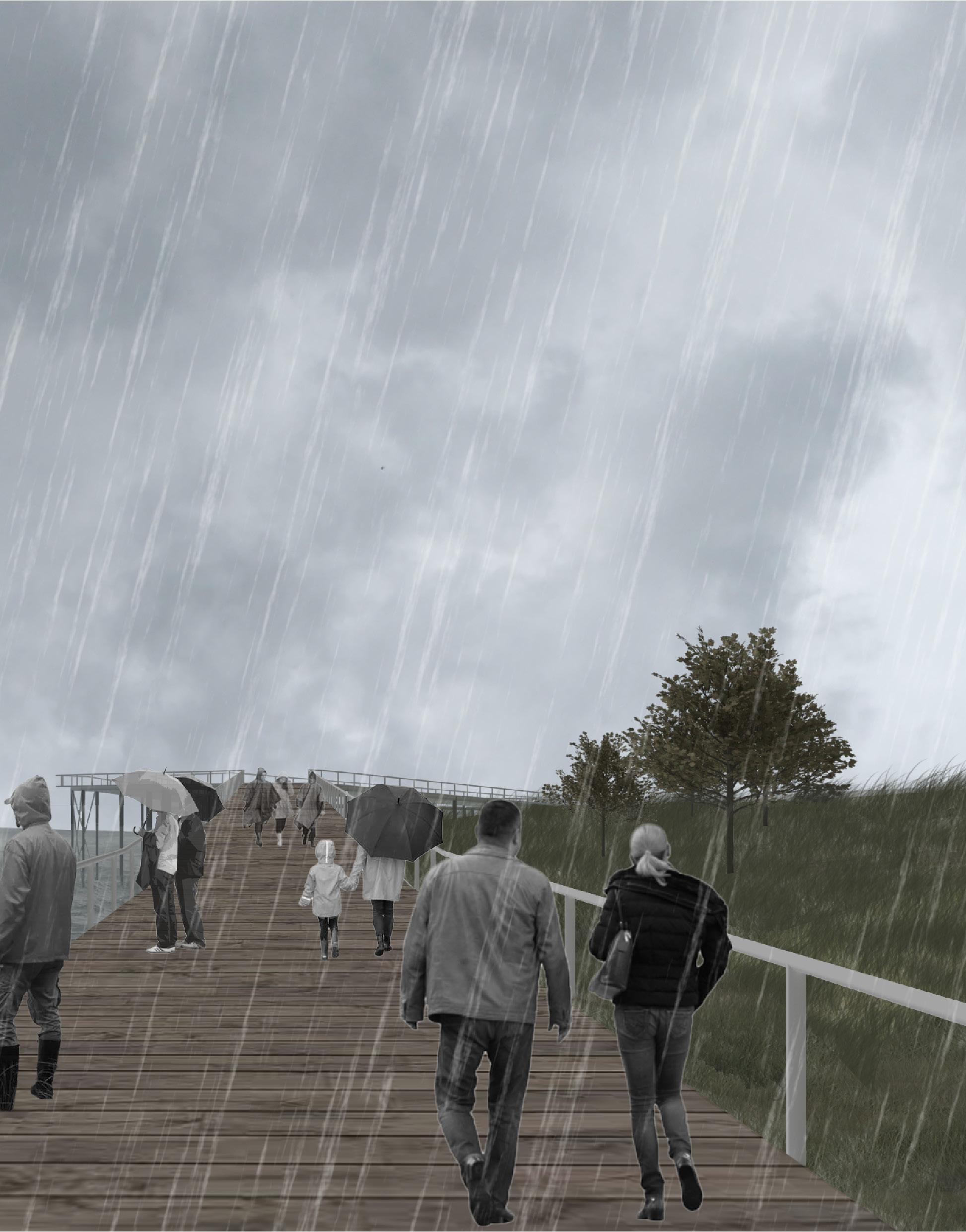
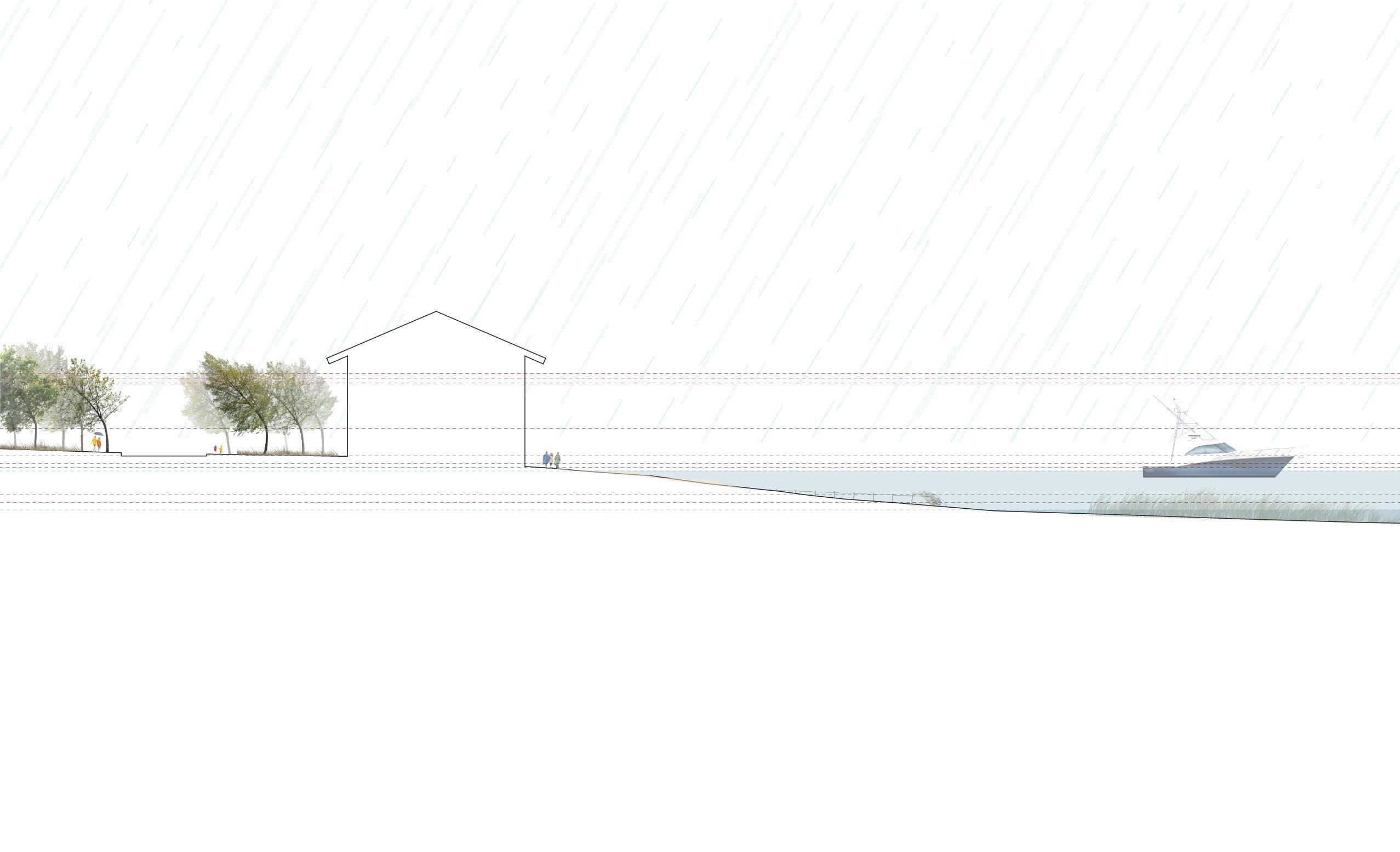
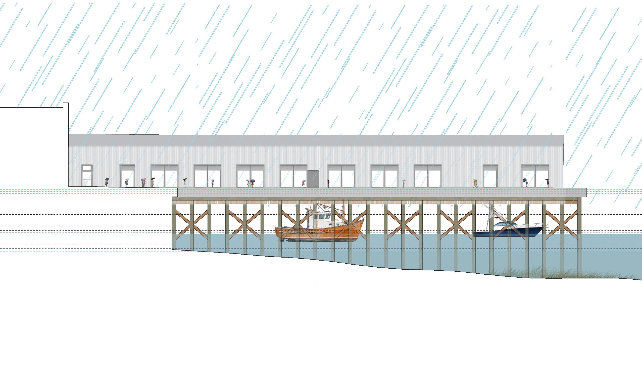
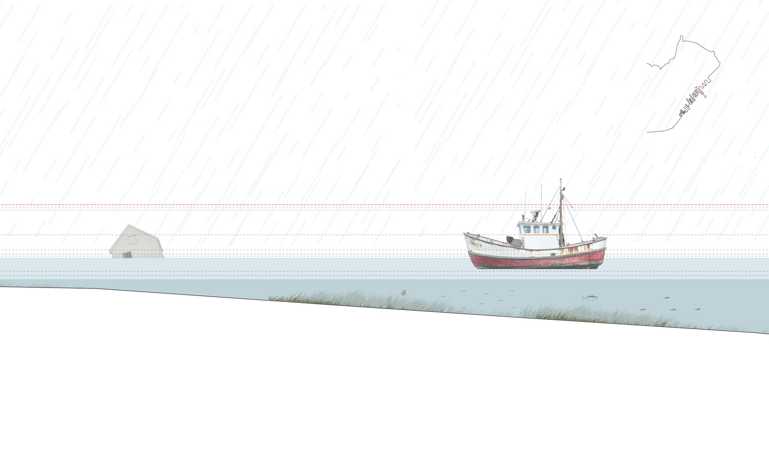
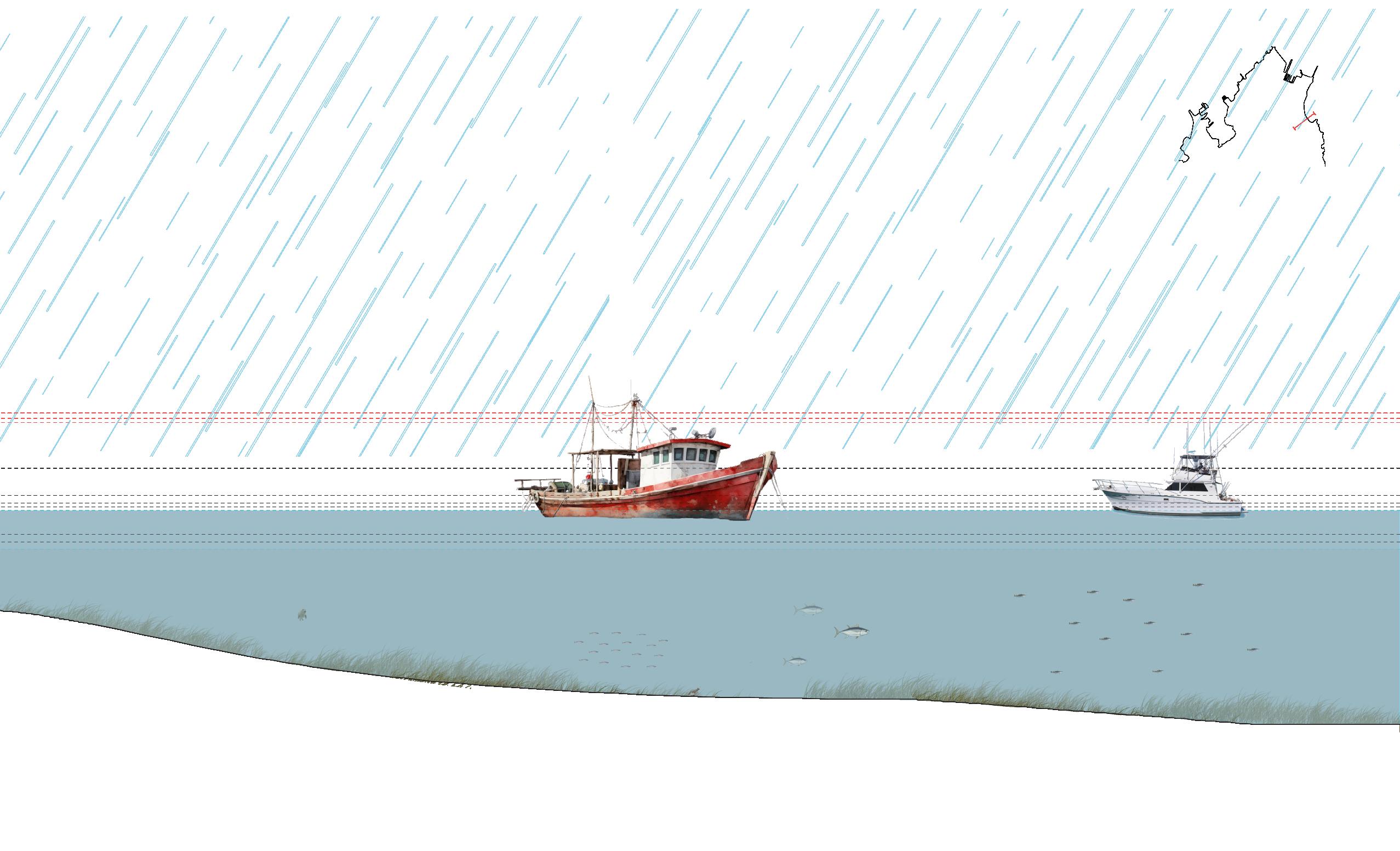
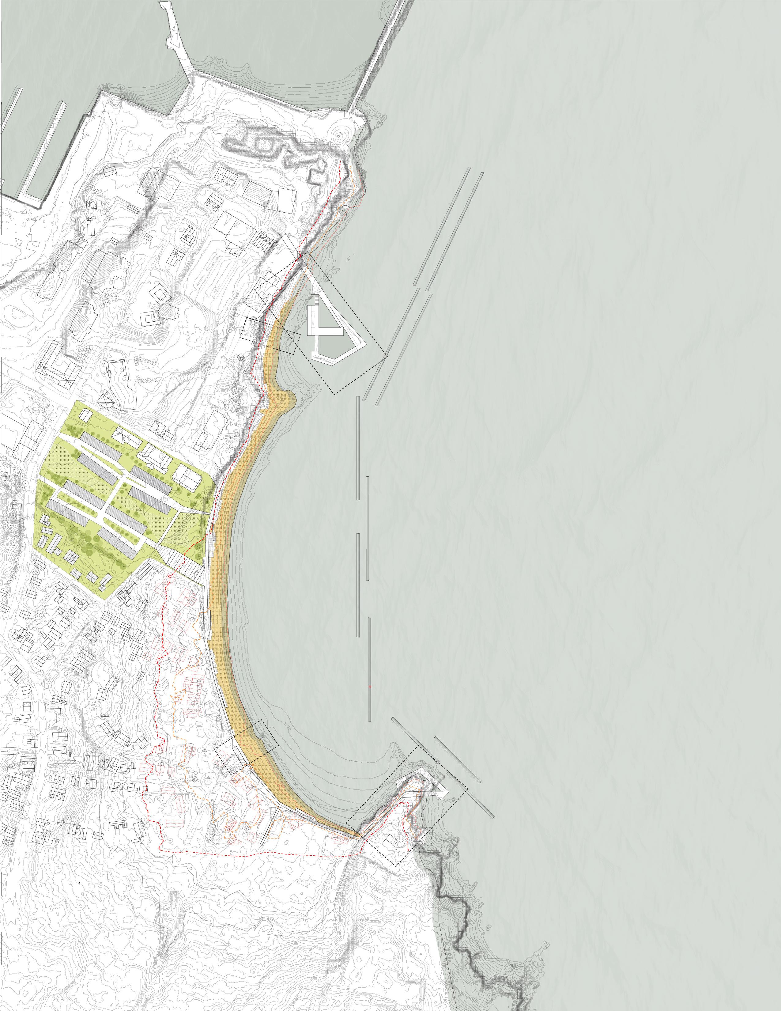
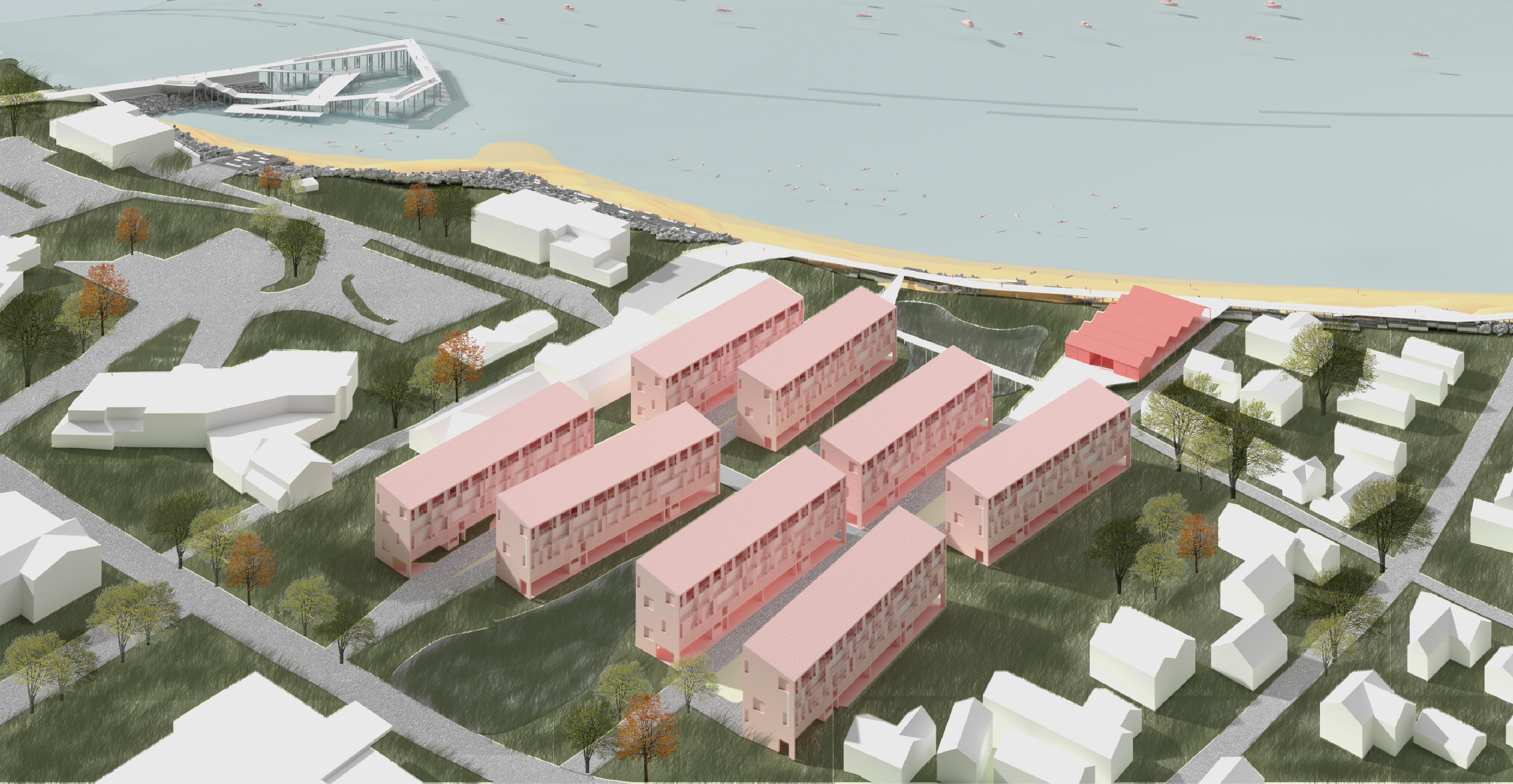
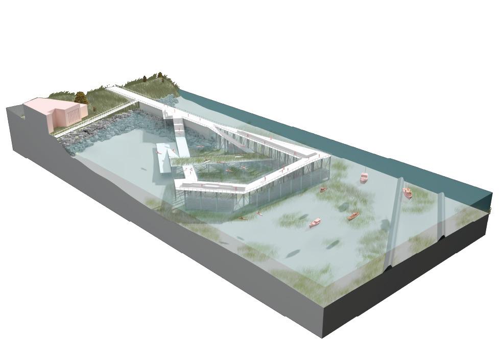
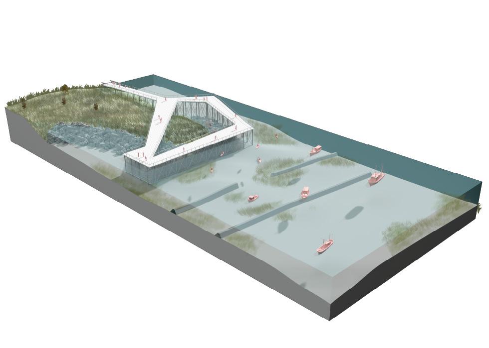
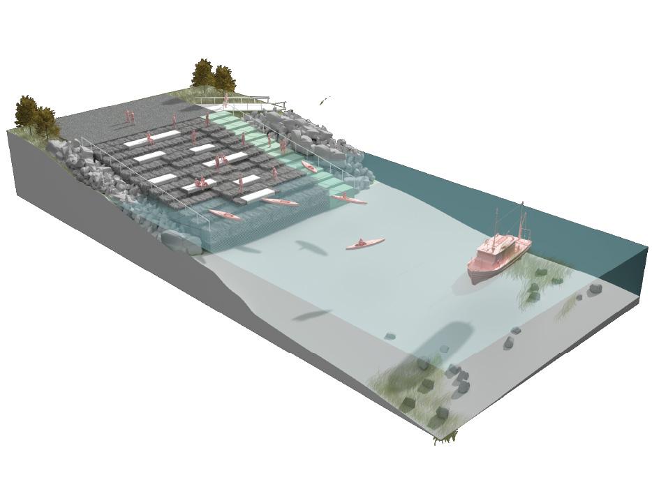
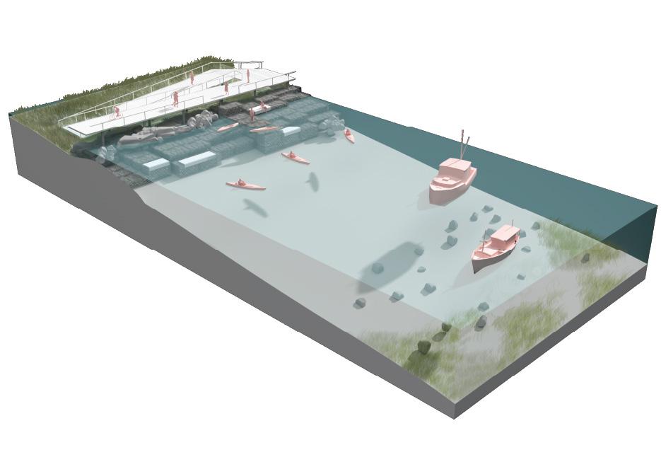
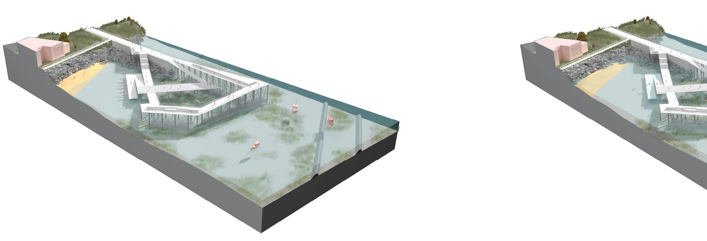
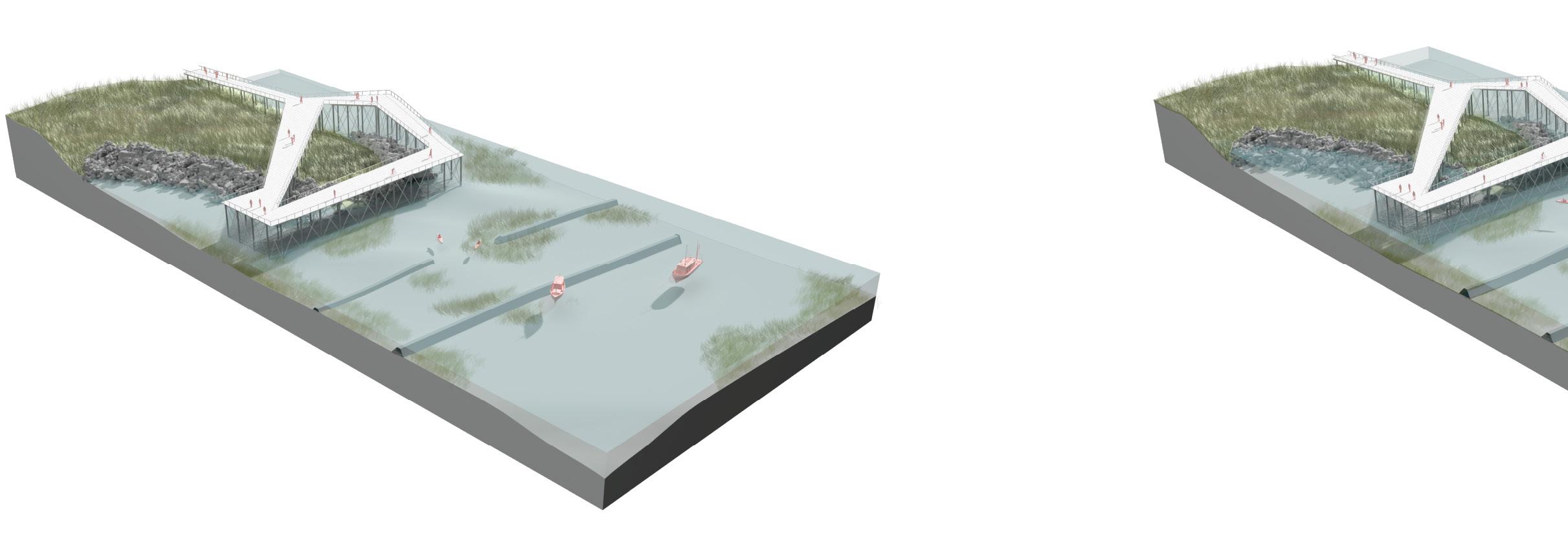
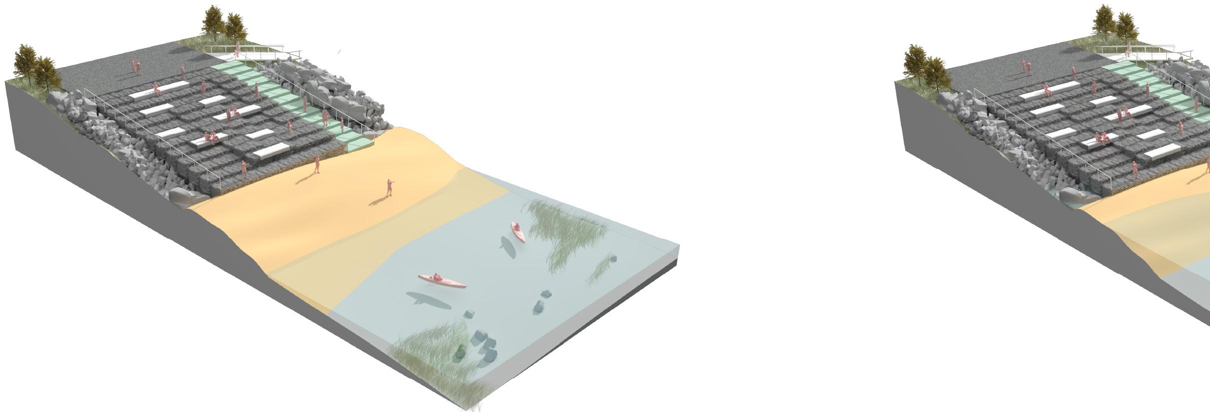
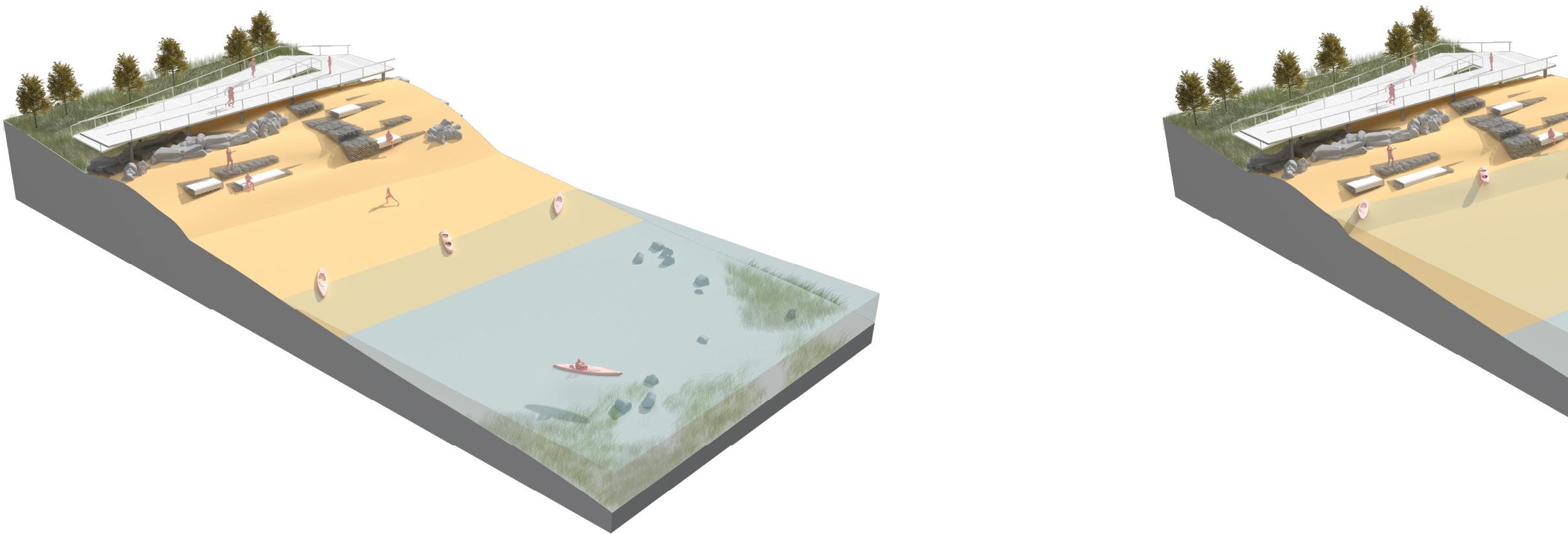
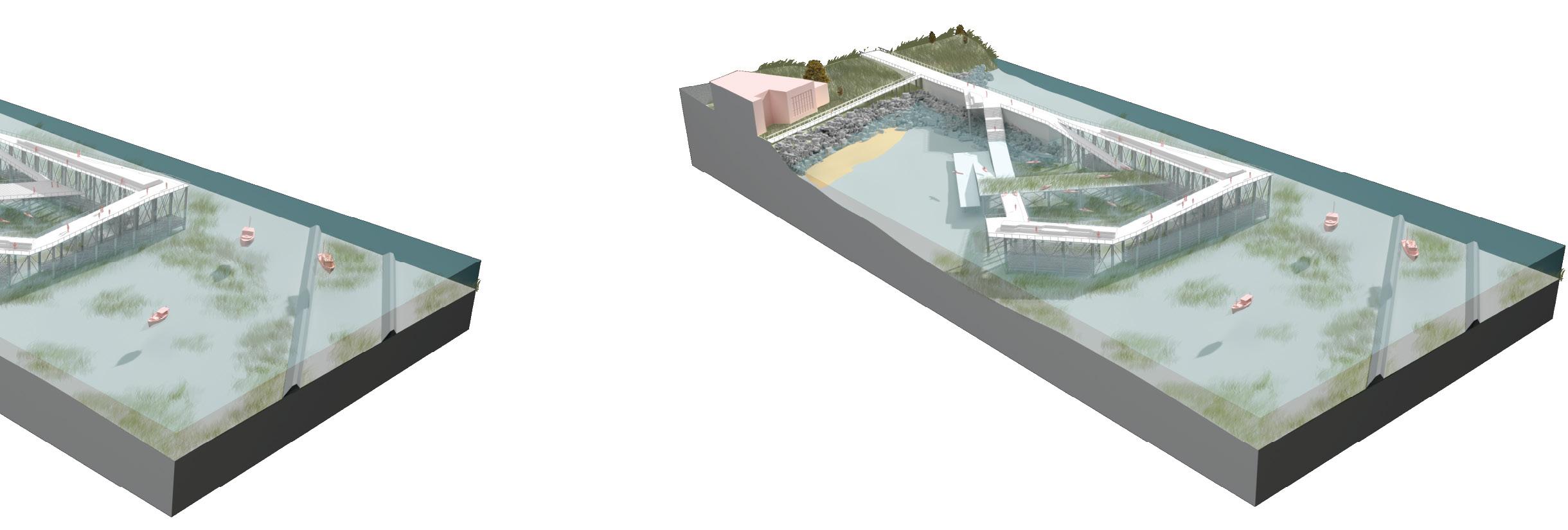
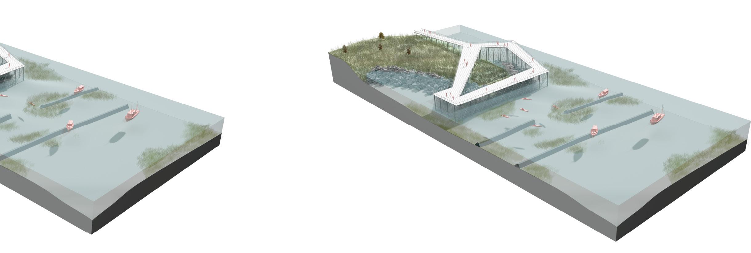
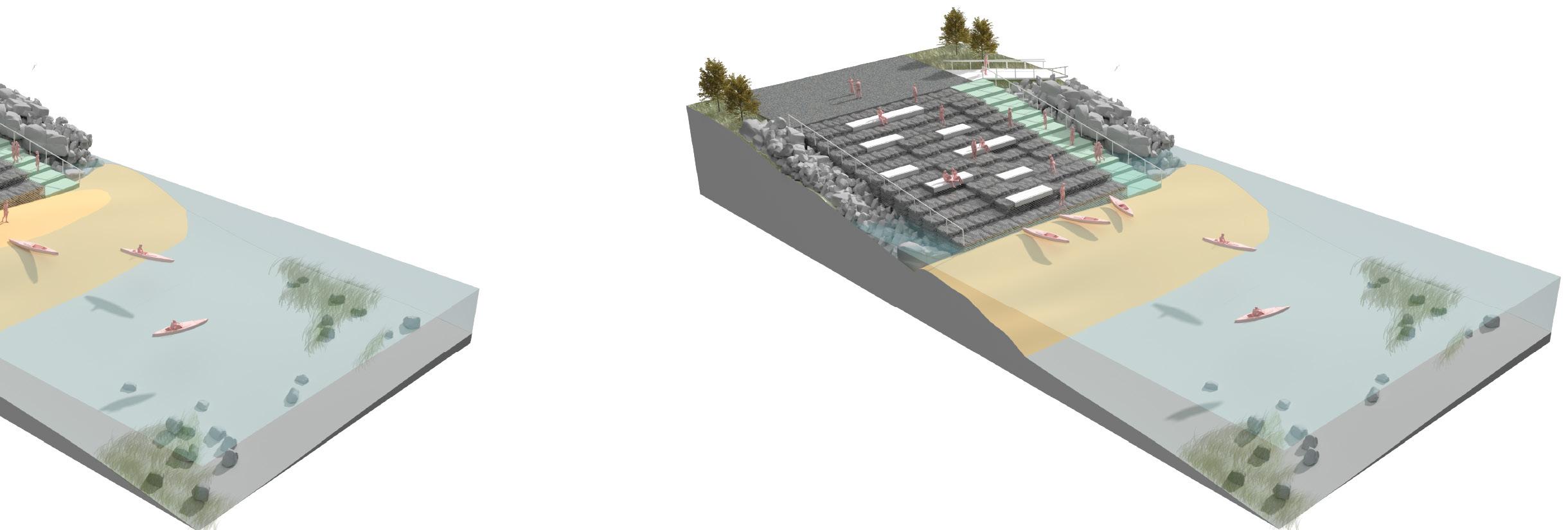
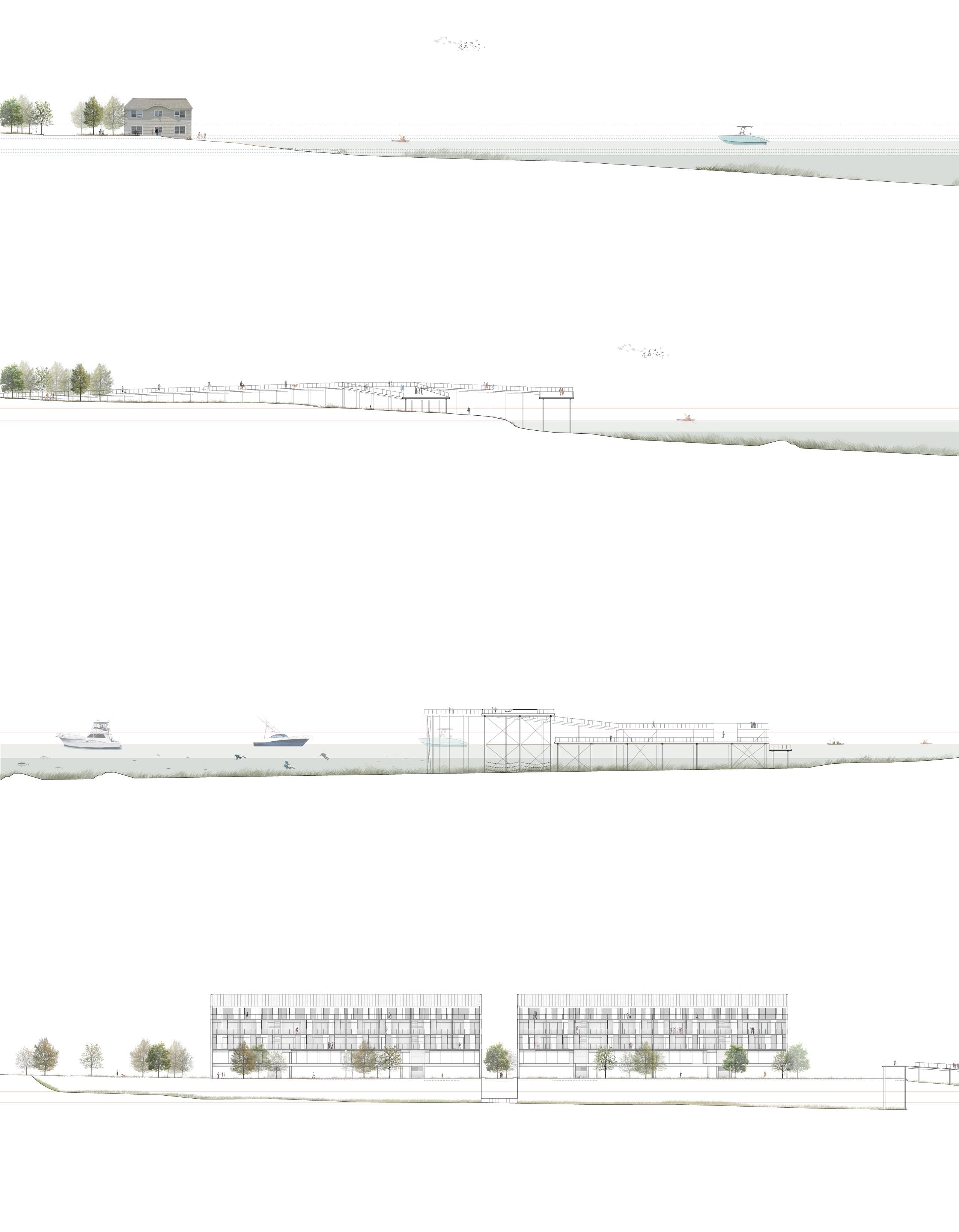
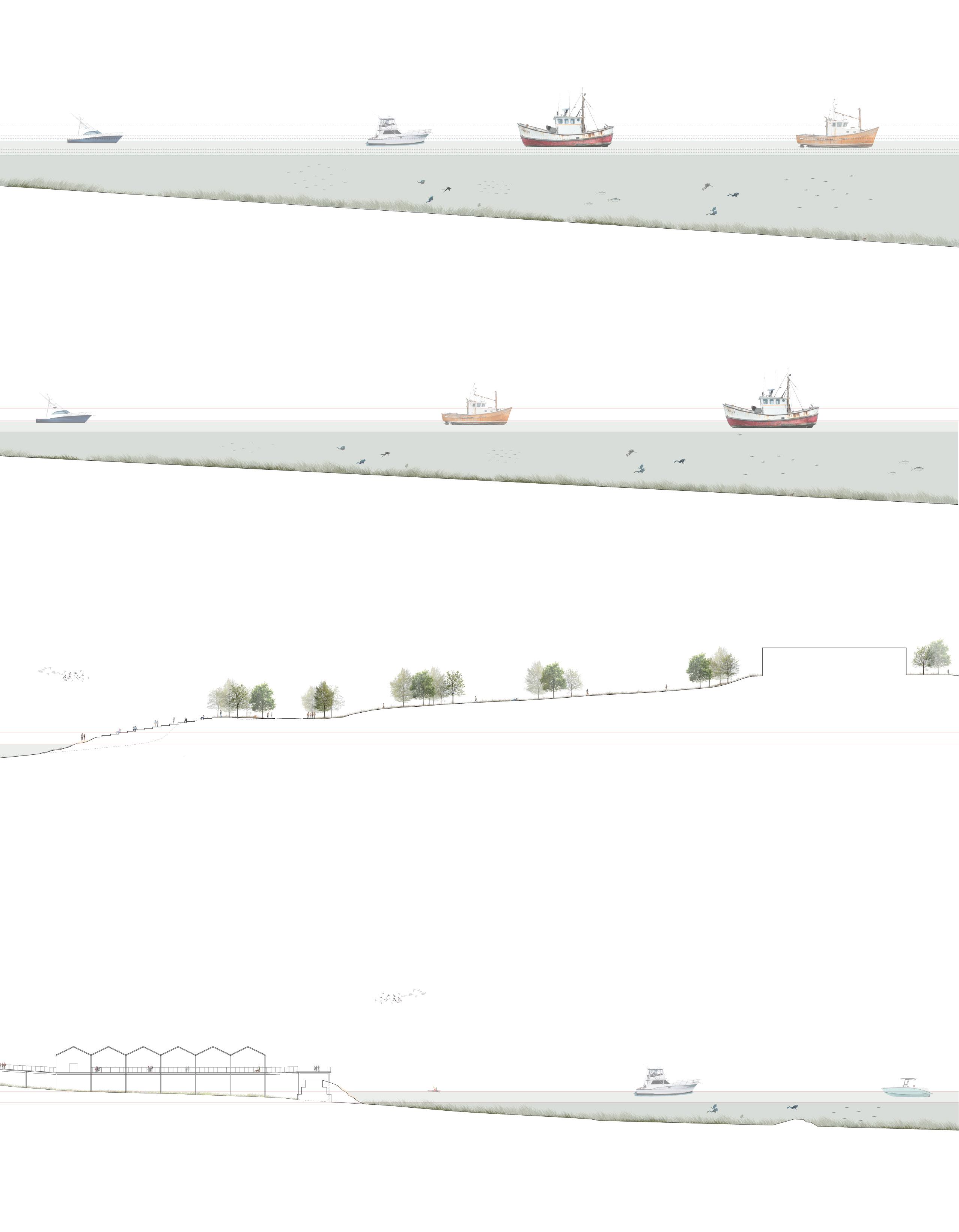
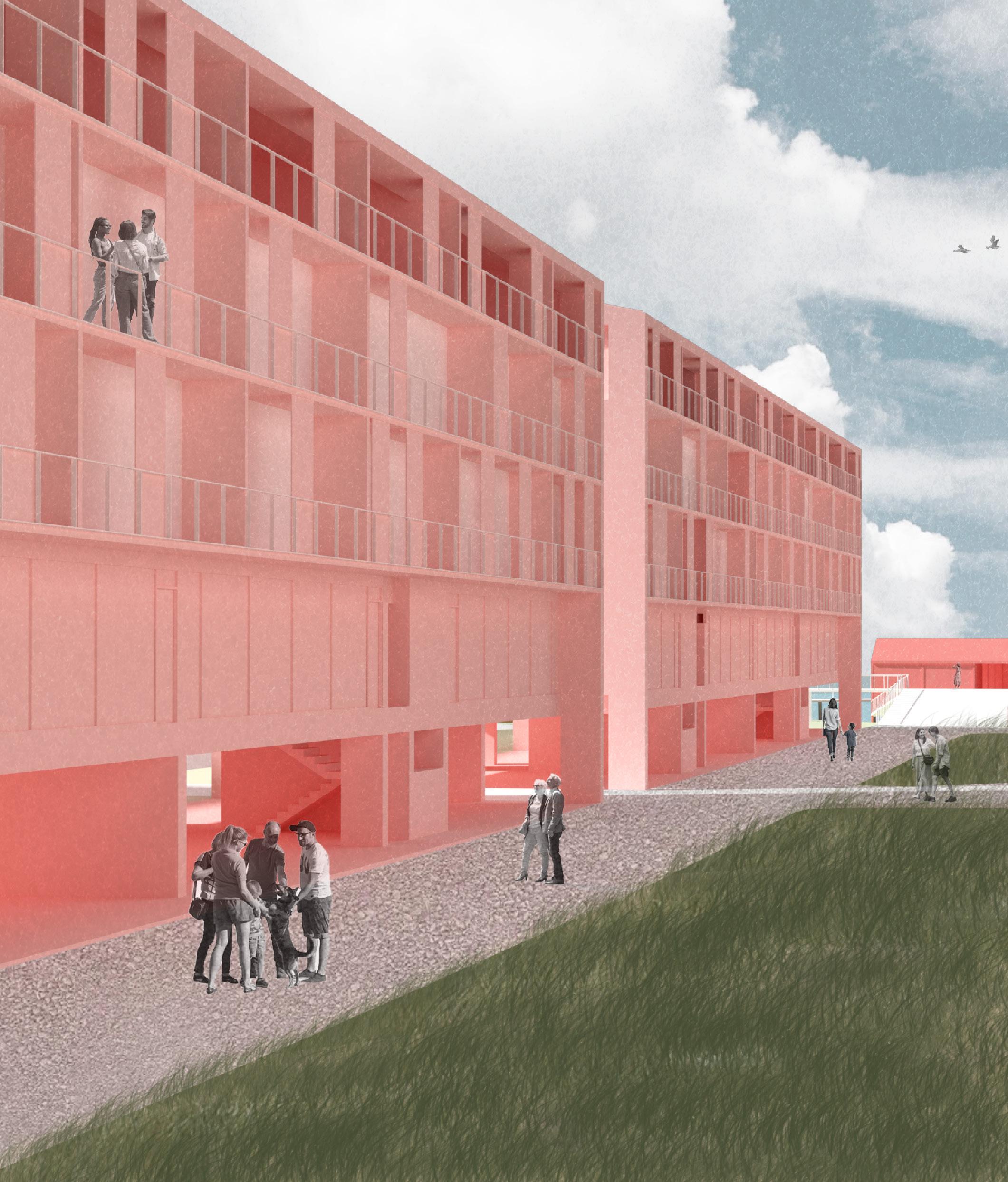
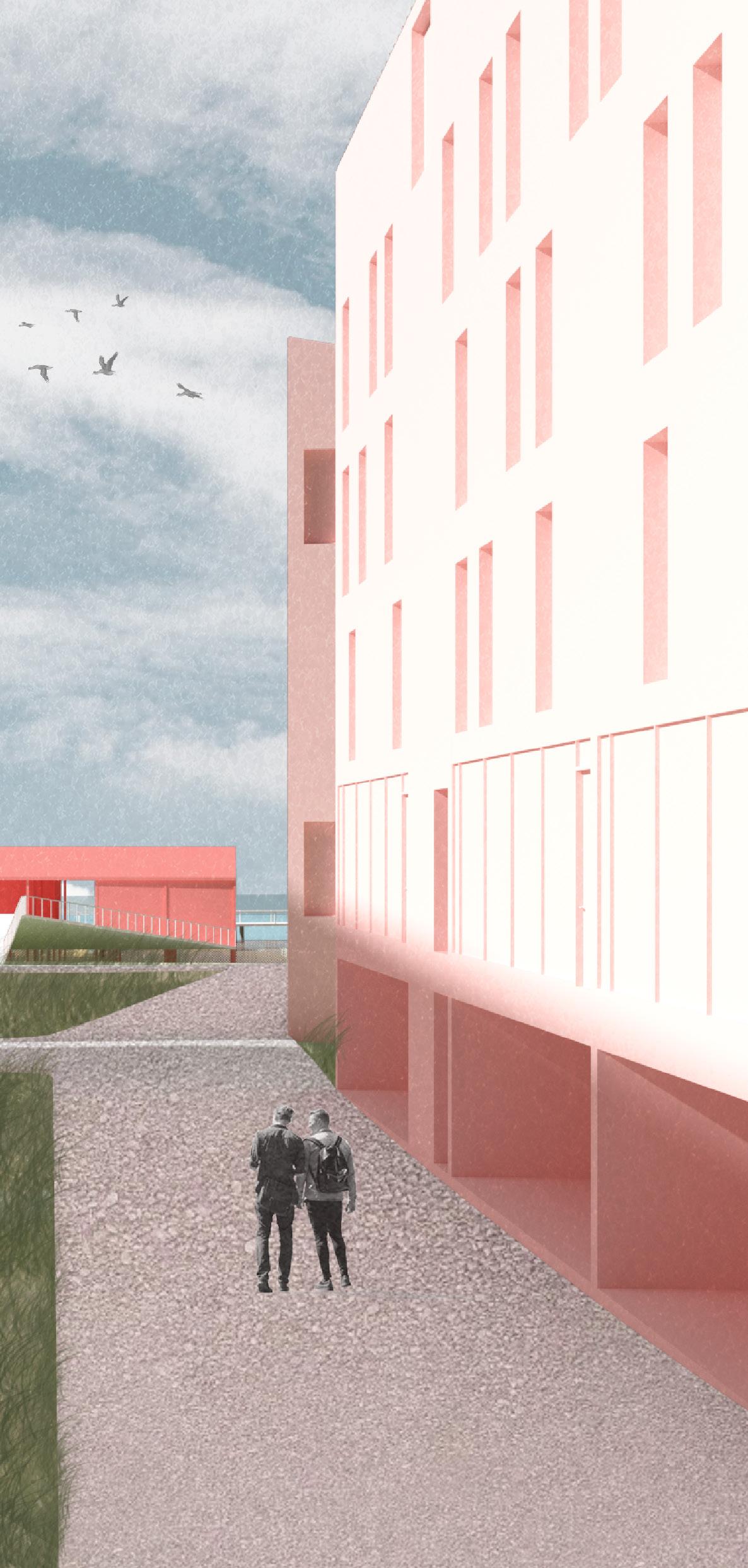
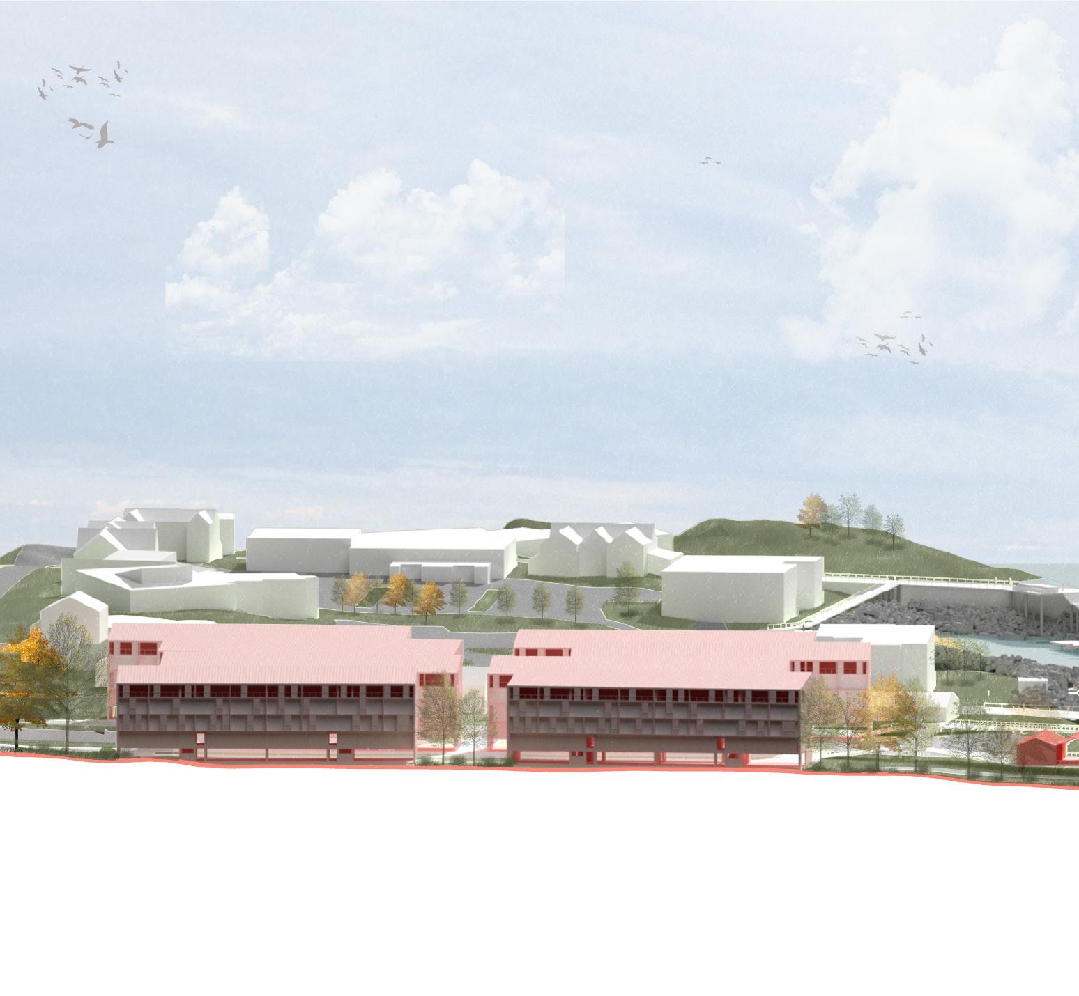
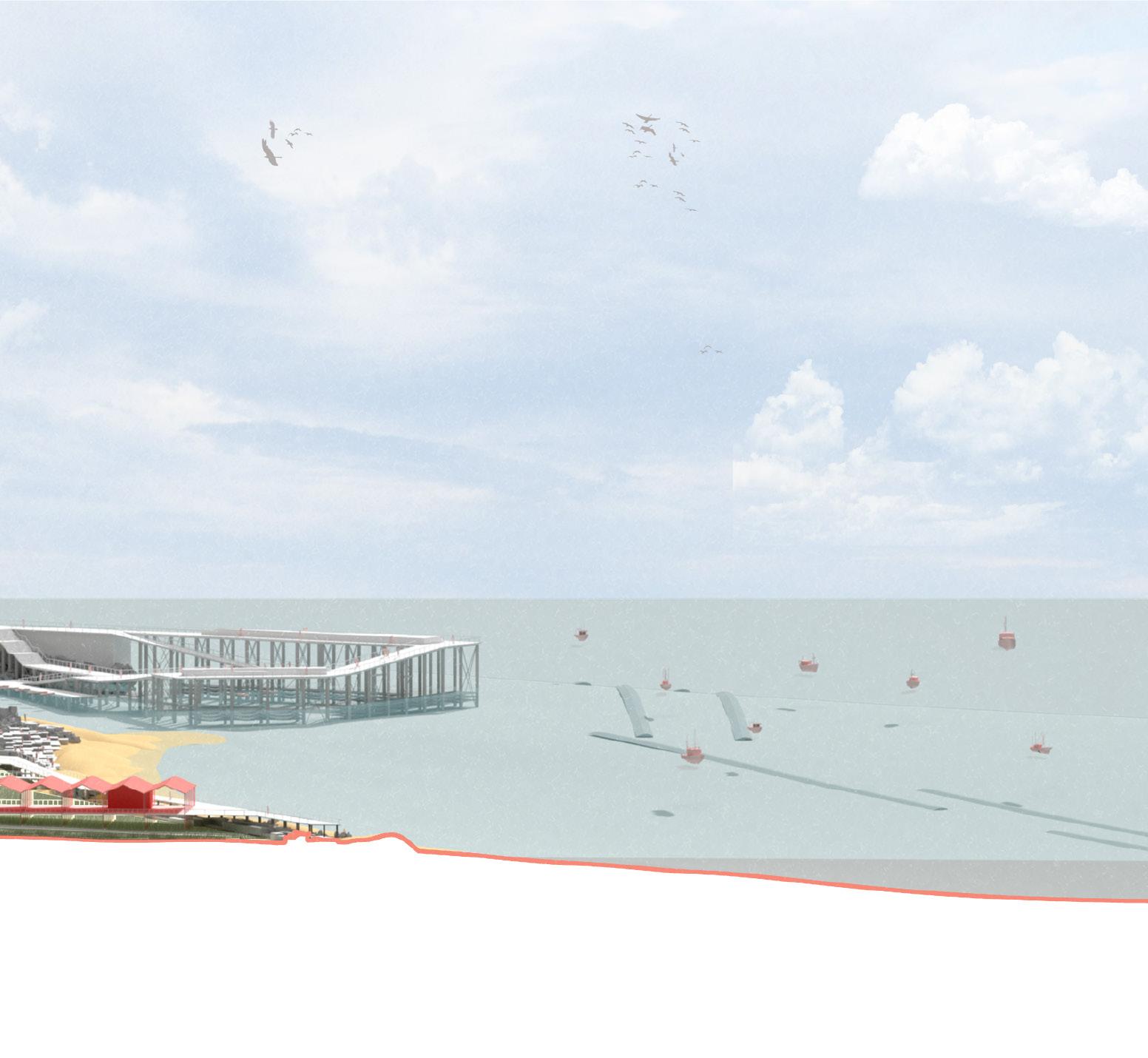
Our group concentrated on Willard Beach in South Portland, one of the hardest-hit areas during the storm. This location, characterized by its diversity and unique appeal, combines beach infrastructure, amenities, housing projects, and accessibility needs. The proposed solutions for this area include the creation of two working and recreational piers that allows access to the water even after flooding, the implementation of gabion wall platforms to prevent erosion while serving as community spaces that can eventually transform into seabeds, and the introduction of elevated platforms to maintain beach accessibility even when submerged. Additionally, reallocated housing complexes have been designed to provide accommodations and reliefs for individuals displaced by rising sea levels.
2024 January Storm: Willard Beach
The storm occurred during the new moon phase, when the combined gravitational pull of the Moon and Sun creates the strongest tidal effect, leading to the greatest difference between high and low tides known as a "spring tide."
January 10, 2024, strong southeast winds generated offshore waves nearly 30 feet high, while the January 13, 2024 event produced waves ranging from 20 to 25 feet. These conditions had particularly devastating effects on Maine’s southeast-facing open ocean coastal areas.
2024 January Storm: Working Water Front
The northward shift of the Gulf Stream and the deflection of the Labrador Current have caused rapid warming and a "regime shift" in the Gulf of Maine. This shift has led to changes in weather patterns and unprecedented events.
All three fishing shacks at Willard Beach were completely destroyed by the storm. Preservation efforts had been ongoing in recent years, as these shacks were the last remaining from the region's fishing peak in the 1800s.
SLR 14.57’
Bobby Zhao
Willard Beach Proposal Amidst Sea Level Rise
1. Southern Maine Pier For Leisure & Oyster Farm
2. Returning A Legacy: Fisherman’s Point Pier
3. Gabion Wall Platform Against Erosion
4. Beach Accessibility Walkway With Future Water Activities
2100 Far Term: 8.8’ Sea Level Rise
Proposed (Current Condition): +0 SLR
Proposed (Current Condition): +0 SLR
Proposed (Current Condition): +0 SLR
2070 Mid Term: +3.3’ SLR
2070 Mid Term: +3.3’ SLR
2070 Mid Term: +3.3’ SLR
2070 Mid Term: +3.3’ SLR
Current Sea Level (+0.0 Feet)
Pier
Current Sea Level (+0.0 Feet)
Maine Community College Pier
Medium Term Sea Level: Year 2070 (+3.9 Feet)
Proposed Housing Complex
Far Term Sea Level: Year 2100 (+8.8 Feet)
Southern
Fisherman’s Point
Willard Beach
Cornerstone Muse: City of Arts
Studio Professor: Annette Lecuyer | Spring 2024
Studio Partner: James Metzger
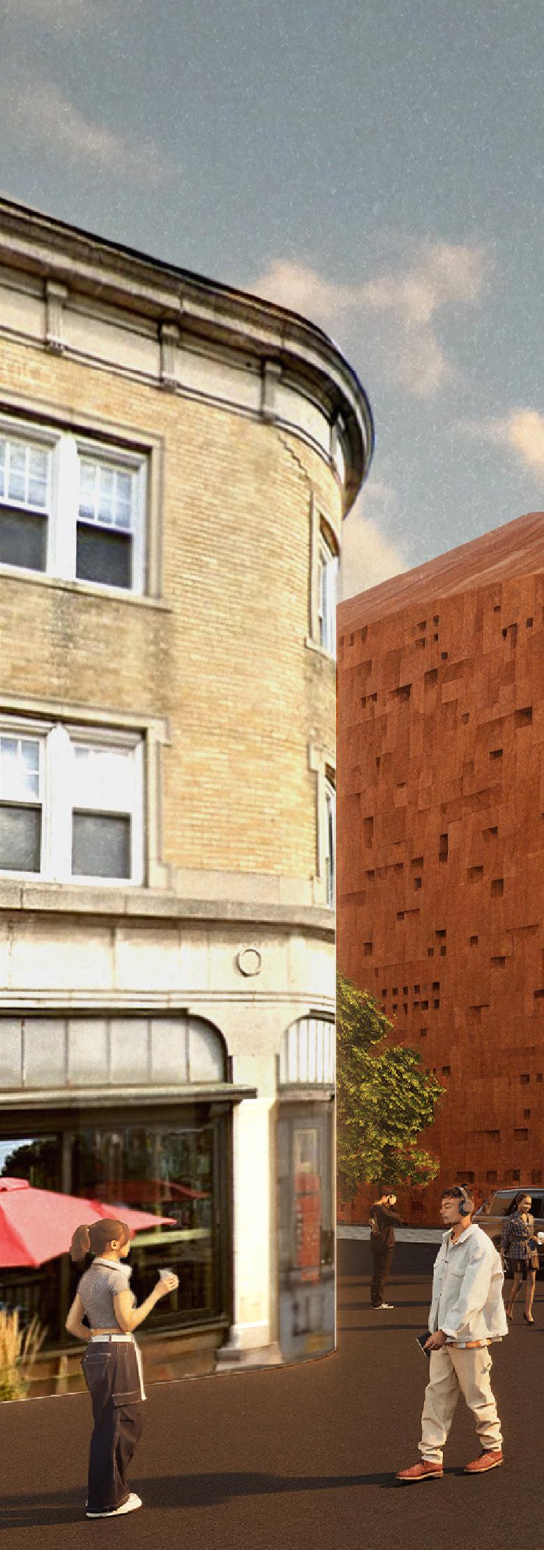
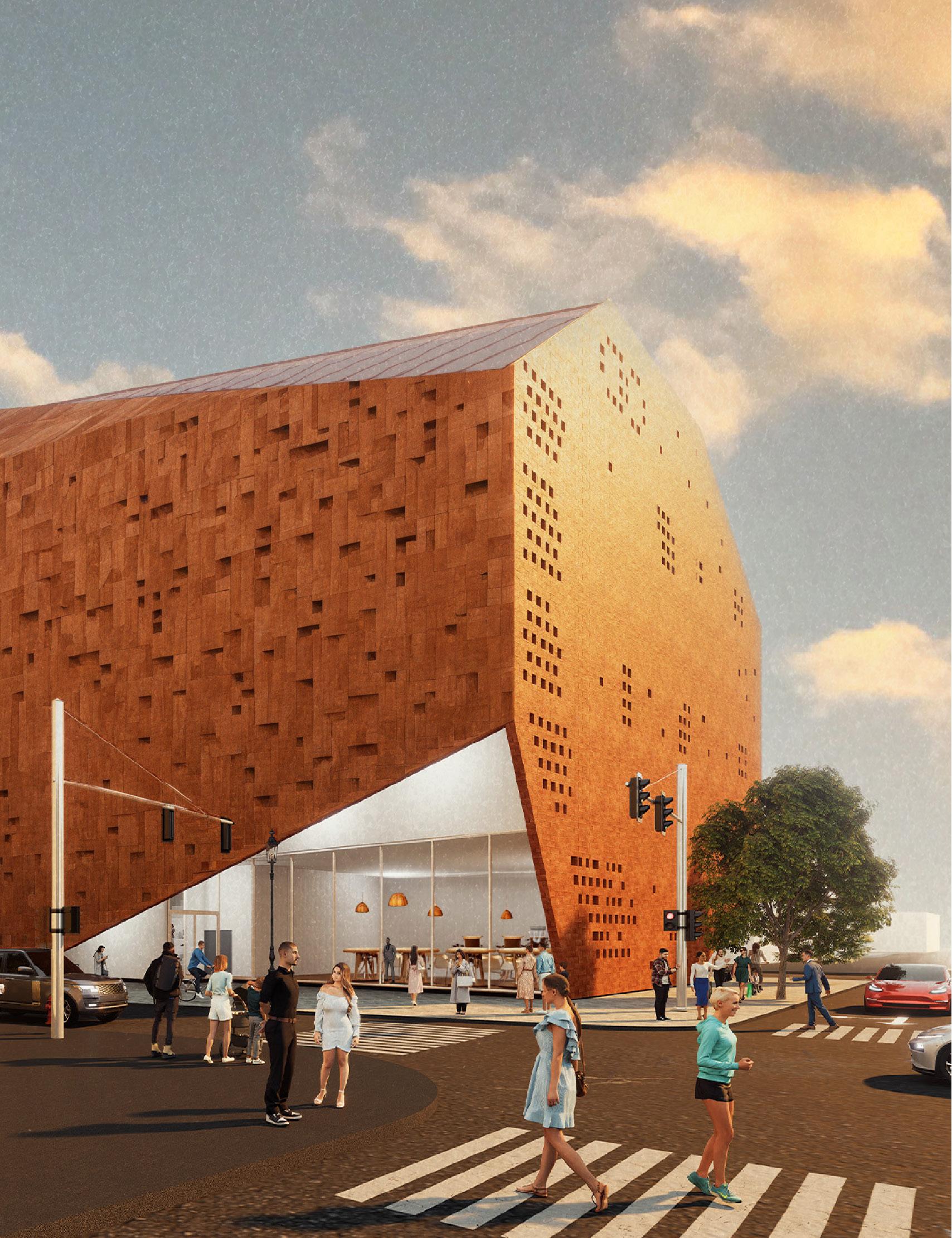
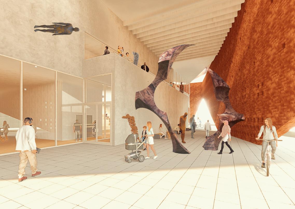
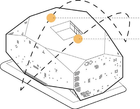
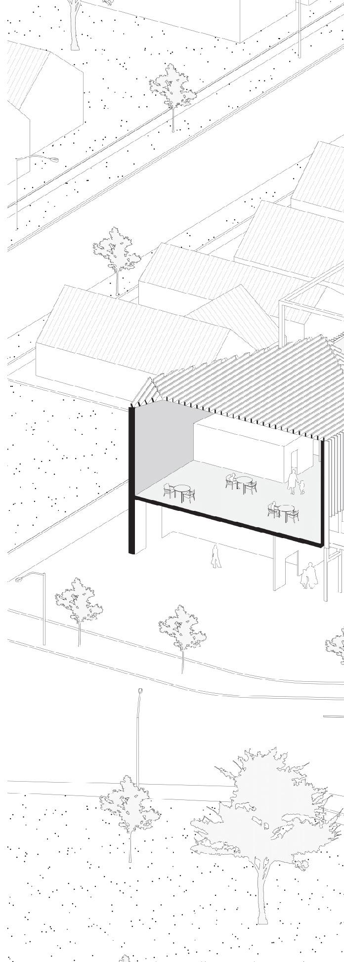
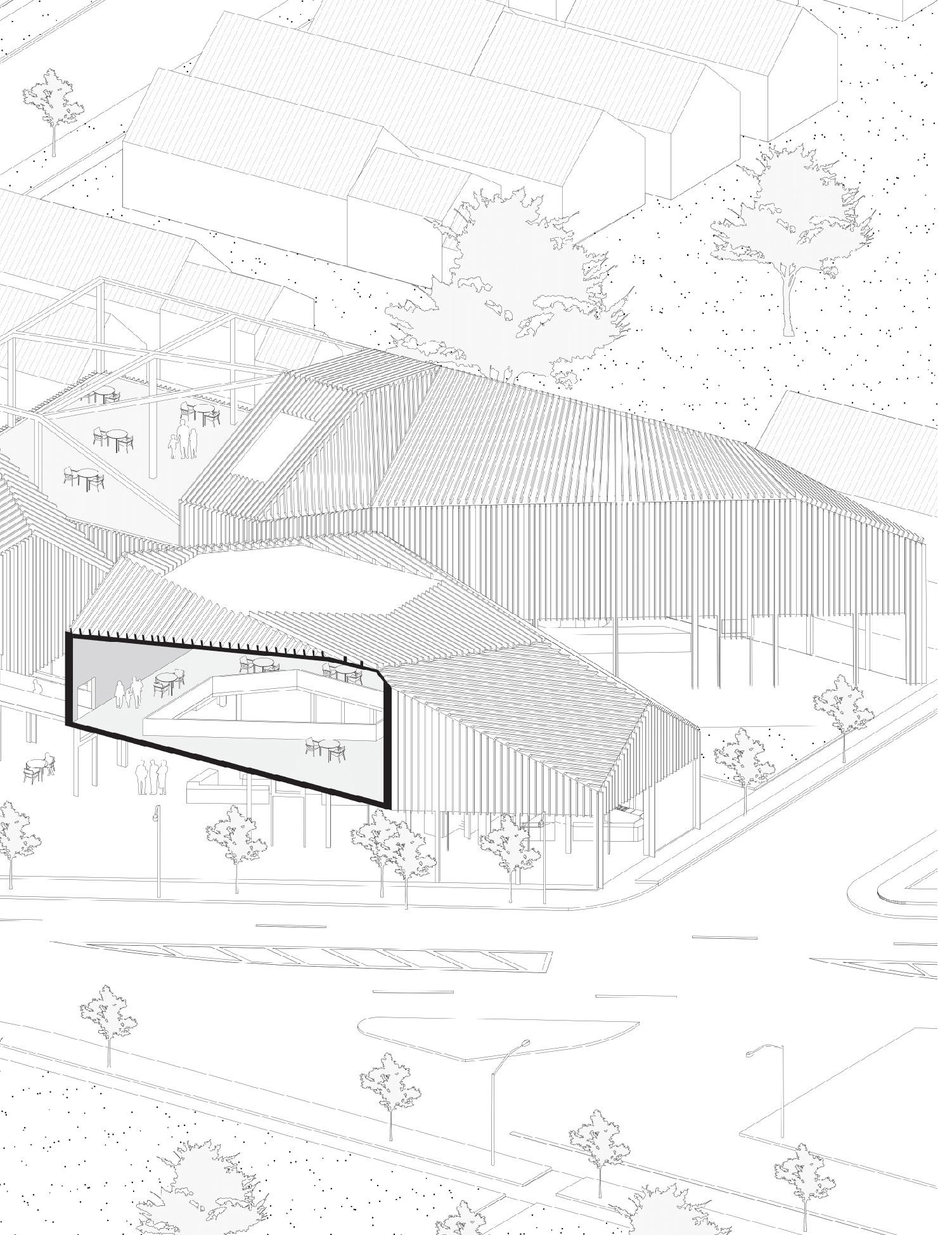
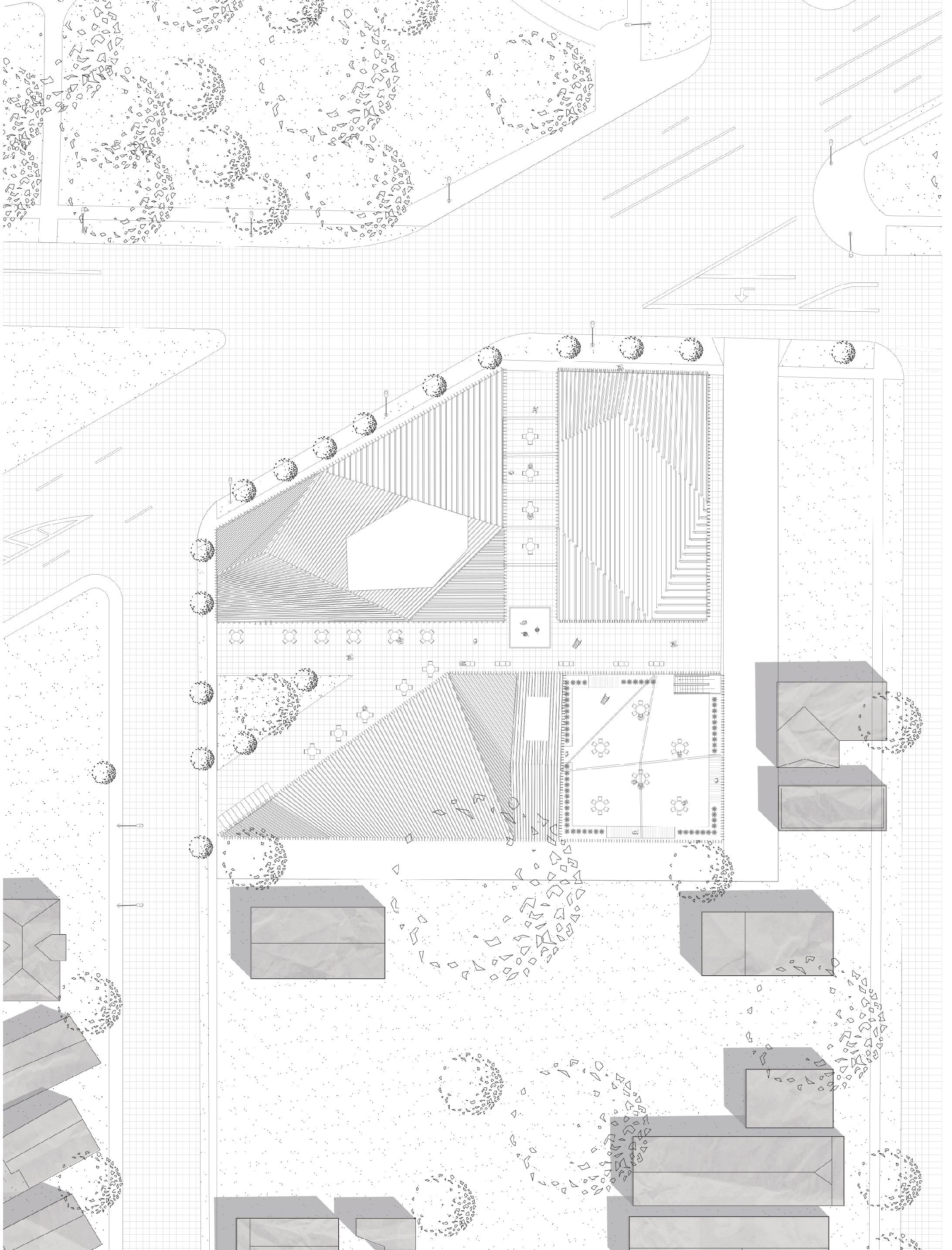
The proposed museum design at the intersection of Allen St and Delaware Ave in Buffalo is a bold and innovative addition to the cityscape, aiming to both enrich the cultural landscape and rejuvenate the urban fabric. The key concept driving this design is the lifting of corners, a deliberate architectural move that serves multiple purposes.
One of the primary objectives is to create inviting and functional spaces for the community. By lifting the corners of the building, the design opens up areas at street level, providing pedestrians with visually appealing, sheltered spaces to gather and interact.
The front of the museum is set back, creating an exterior atrium space that serves as a transition between the street and the interior galleries. This atrium not only enhances the building’s visual appeal but also functions as a welcoming public space that can host events and exhibitions.
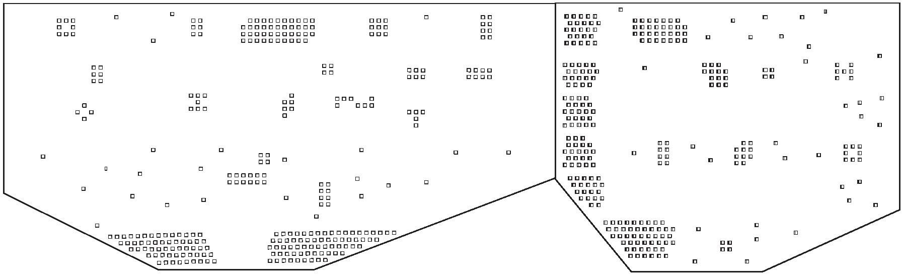
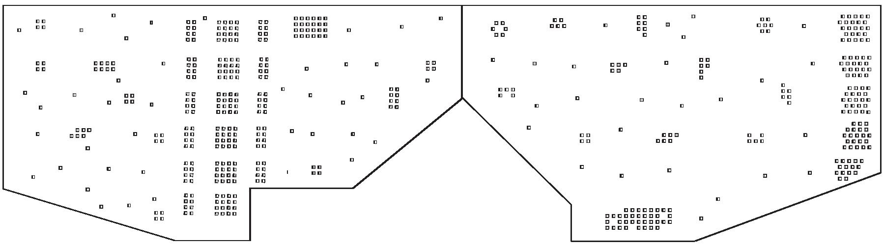
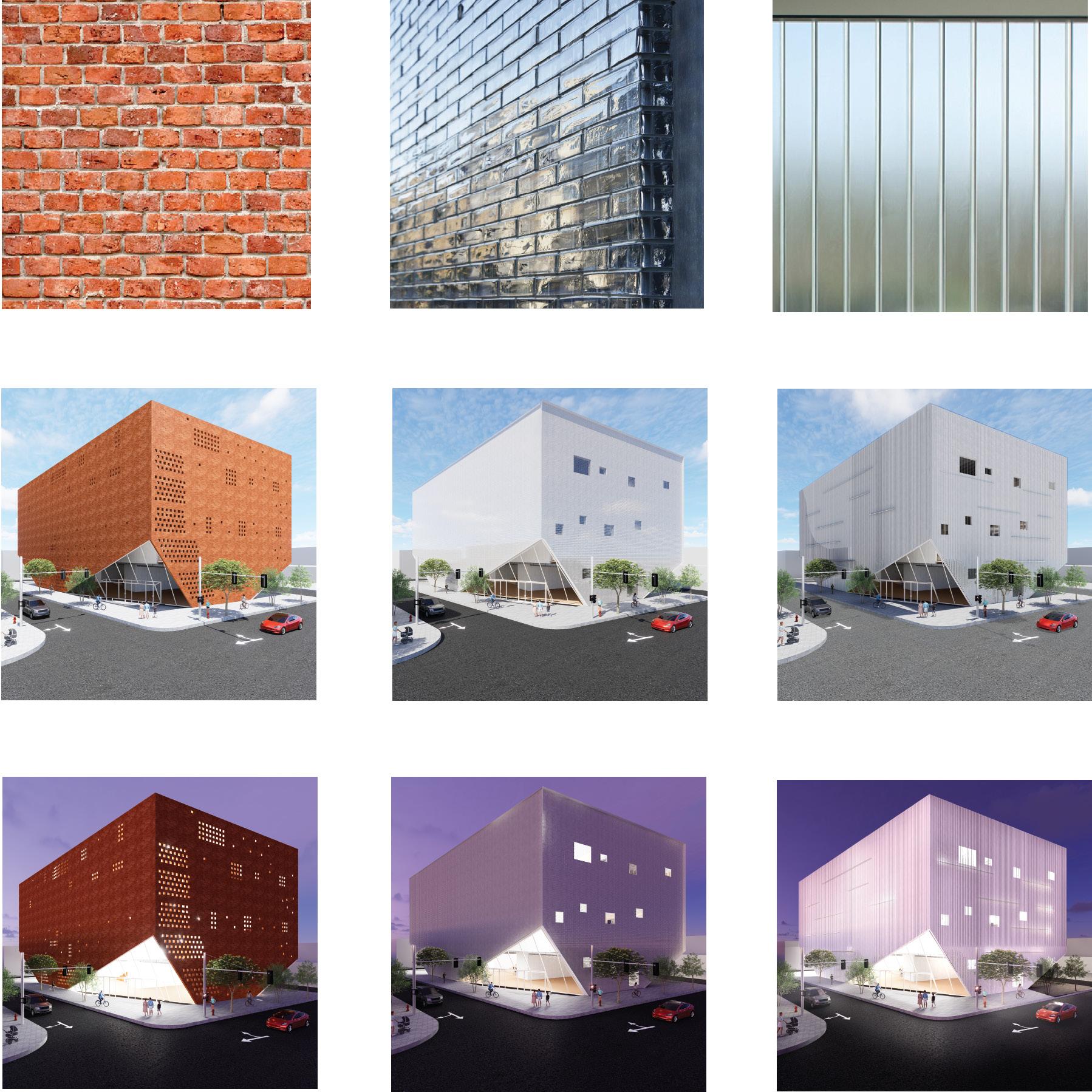
The choice of brick as the facade material is a nod to the surrounding context of Buffalo’s brick houses. However, the bricks are not traditional in their appearance; they feature punctures that allow light to filter through and soften the heavy material. This adds depth and texture to the facade, creating a dynamic and ever-changing exterior.
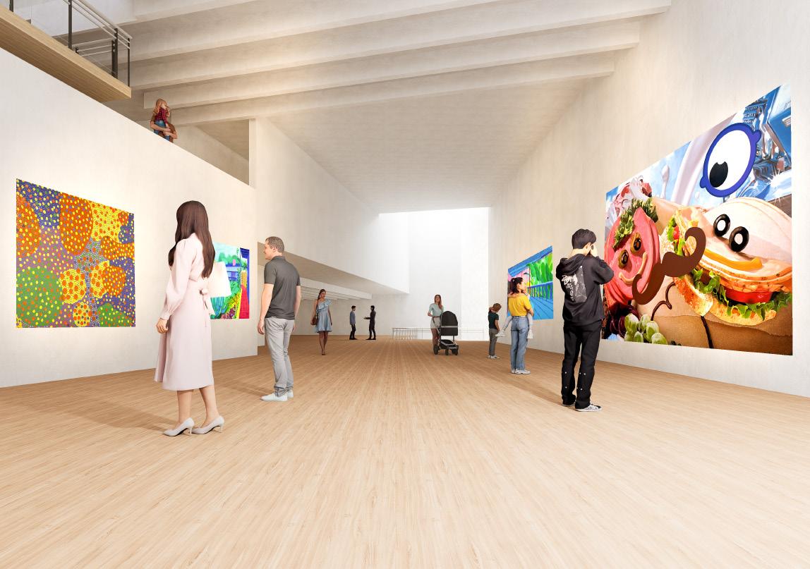
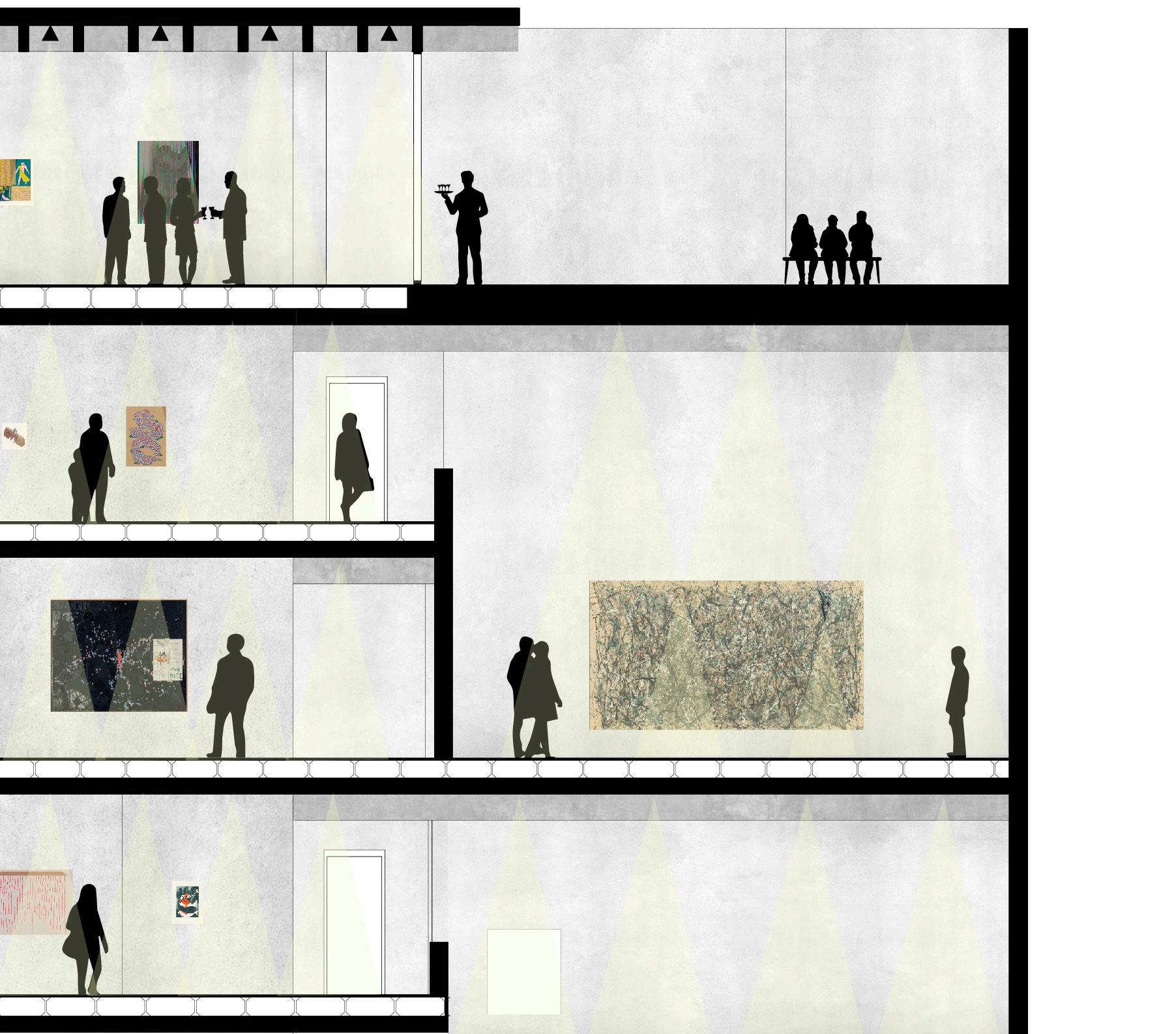
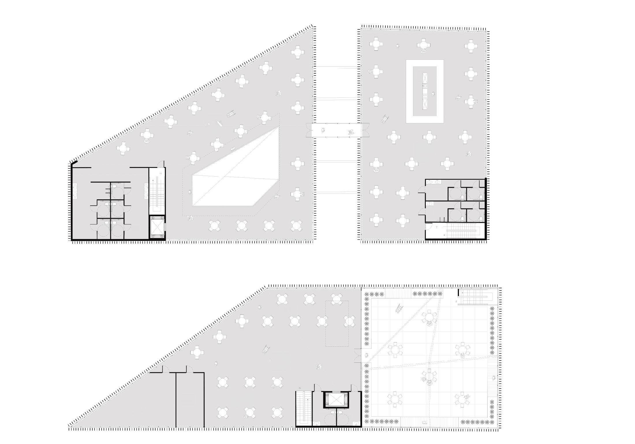
Inside, the design continues to innovate with its use of setback floor plates that are stacked to create unique spatial configurations. These cut corners not only provide visual interest but also serve a functional purpose by allowing daylight to penetrate deep into the galleries. This results in a play of light and shadow that varies depending on the time of day and the angle of the sun, creating a dynamic and engaging environment for visitors.
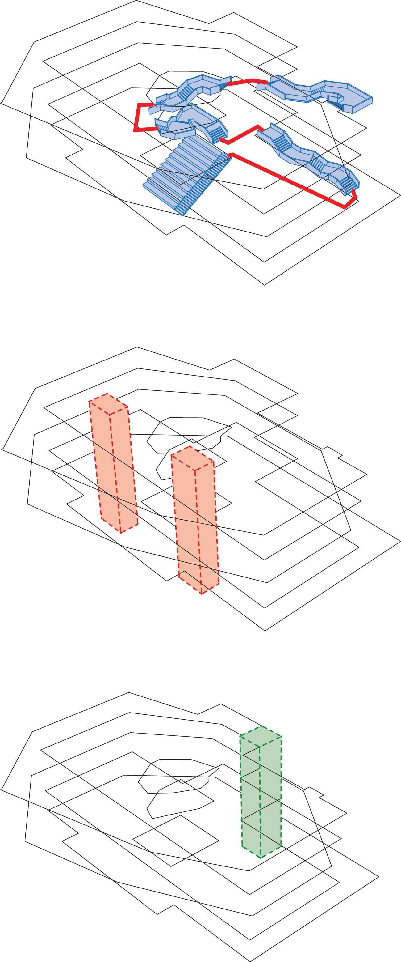
Public Stairs
Elevator
Gallery Type 1: Open Air Gallery
Gallery Type 2: Double Height Space
Gallery Type 3: Light Chimney
North & West Facade
South & East Facade
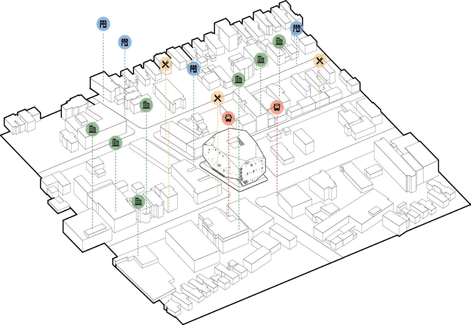
Regional and Community Planning
• Acting as a cultural and educational facility for Allen town
• Proximity to public transportation
• Lifted corners for space to be returned to the community.
• Shop, Café, and Public Forum can operate outside of museum hours.
• Located in a walkable neighborhood and provides services to Buffalo Medical Corridor.
Long Life Loose Fit
• Spaces within the building are flexible. By limiting the amount of walls this allows for a myriad of configurations.
Land Use
• Brown Field Reuse.
• Replacing a gas station with on grade parking, transforming it into a cultural site.
Bioclimatic Design
• Use of thermal wells to reduce mechanical load.
• Small wall to window ration preventing leakage.
Light and Air
• Four generous light chimneys provide the main day lighting for the gallery and atrium spaces. While pin hole windows give extra light in areas that need it.
• Light is diffused through the mass of the building.
Materials and Construction
• Structural concrete is made with recycled materials, blast furnace slag.
• Materials can be recycled after their lifetime.
• The use of brick is not only to mimic the area but also, allows façade to eventually be recycled.
Envelope 1: Brick
Envelope 2: Glass Brick
Envelope 3: Channel Glass
Lighting Design
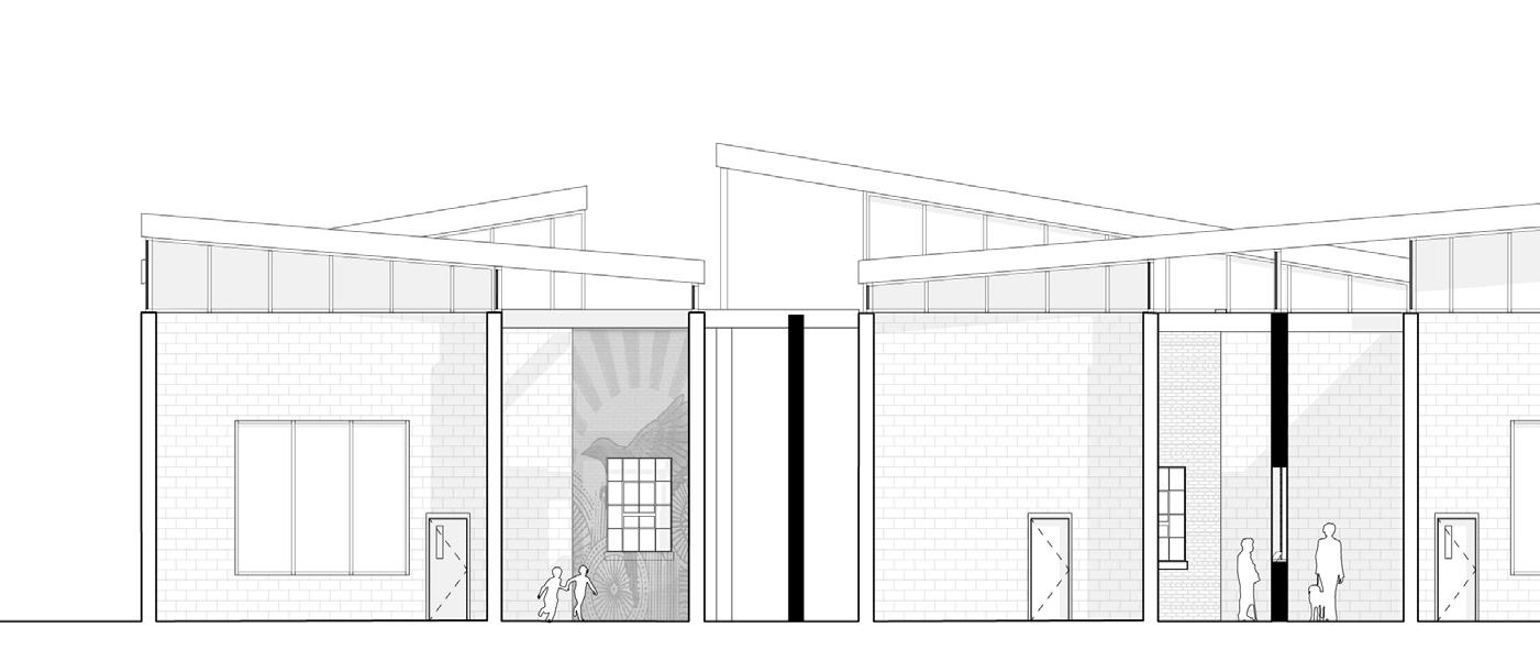
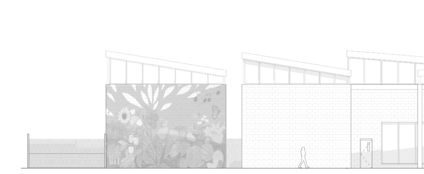
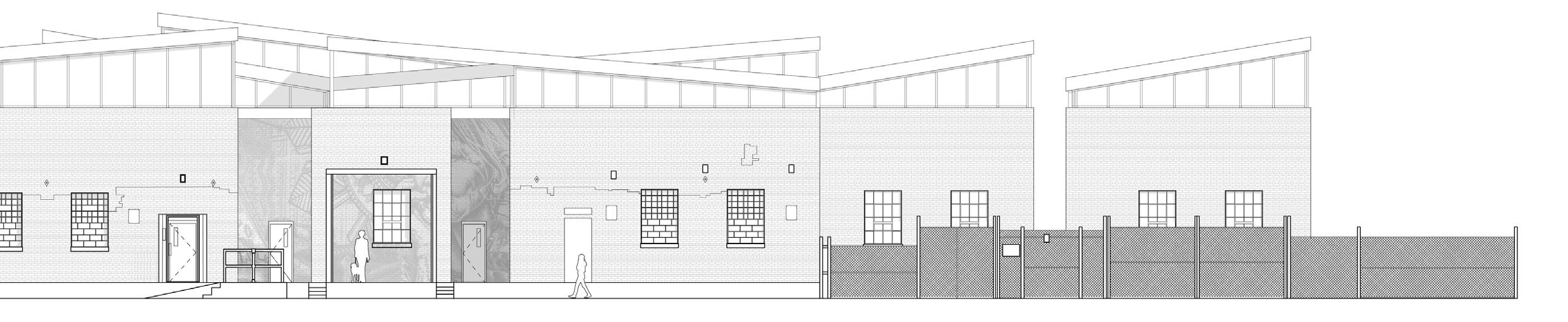
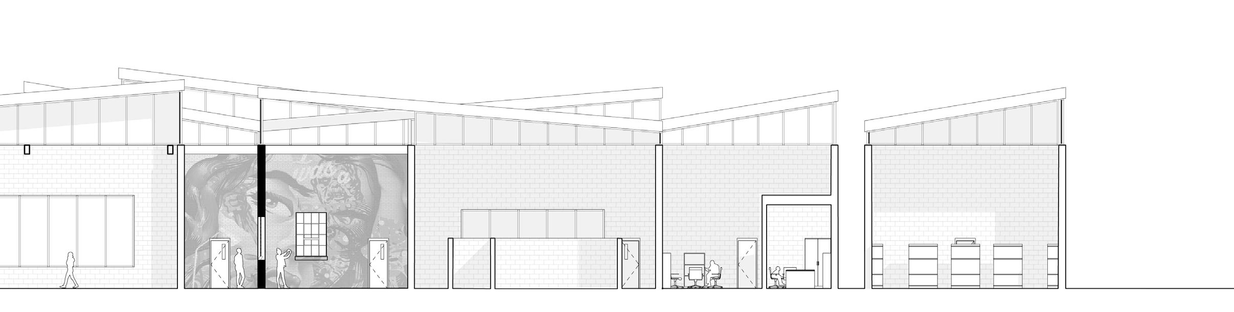
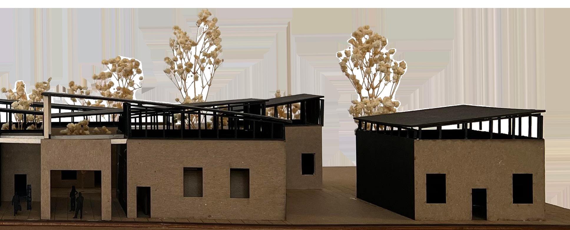
Center For Sustainable Dying: Death of Street Art | Urban Canvas
Studio Professor: Adam Thibodeaux | Fall 2023
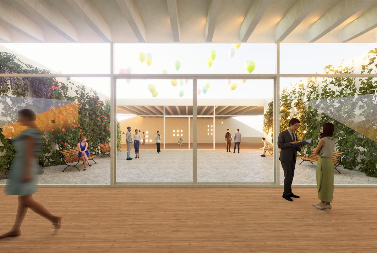
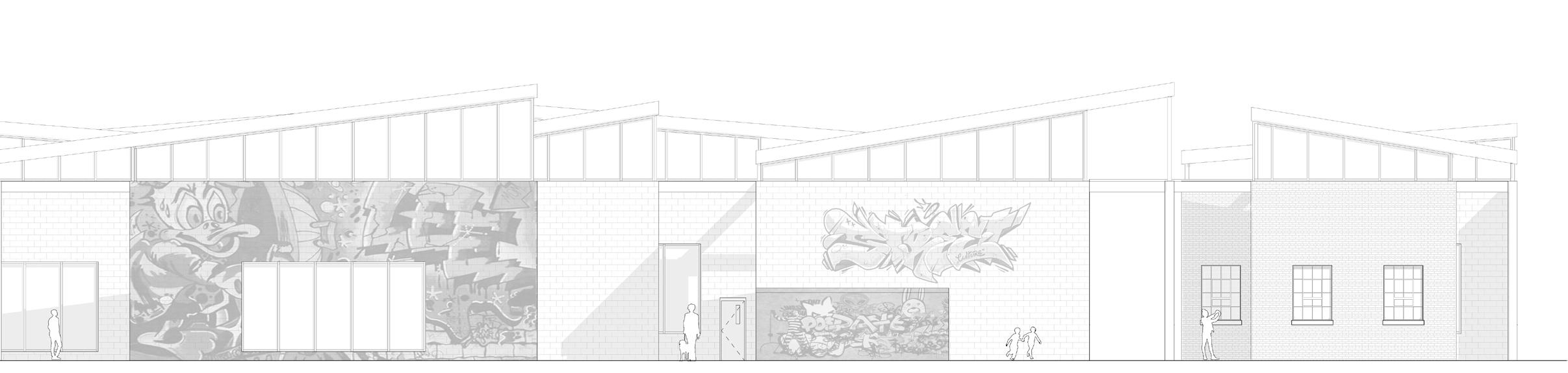
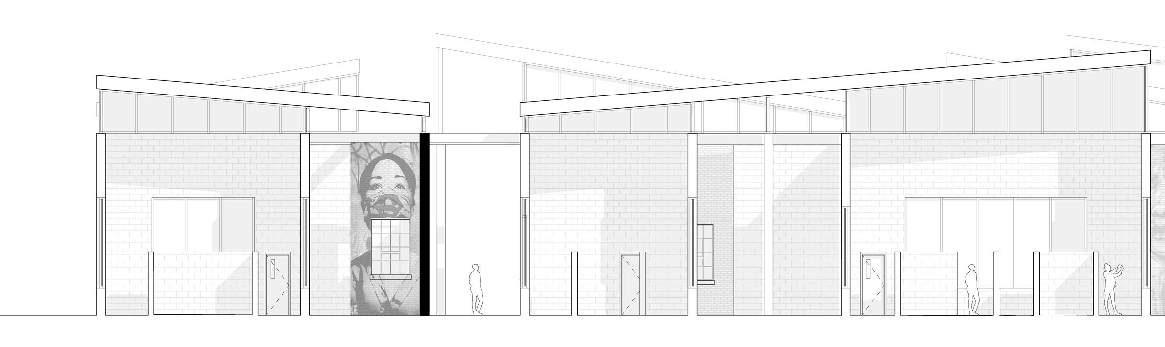
This design proposal envisions a pioneering center dedicated to sustainable artistry and expression, weaving together the realms of sustainable dying and street art.
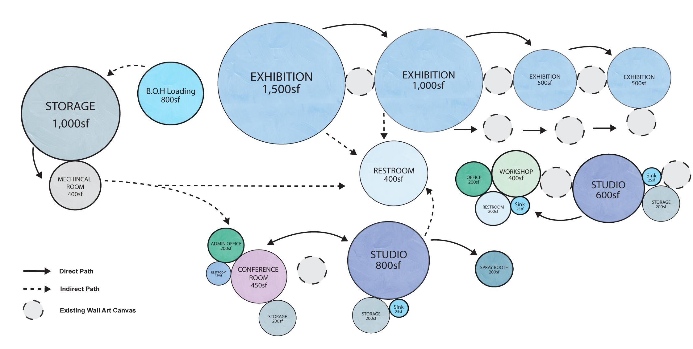
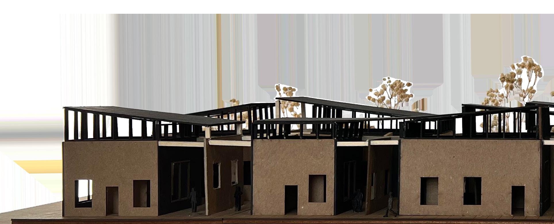
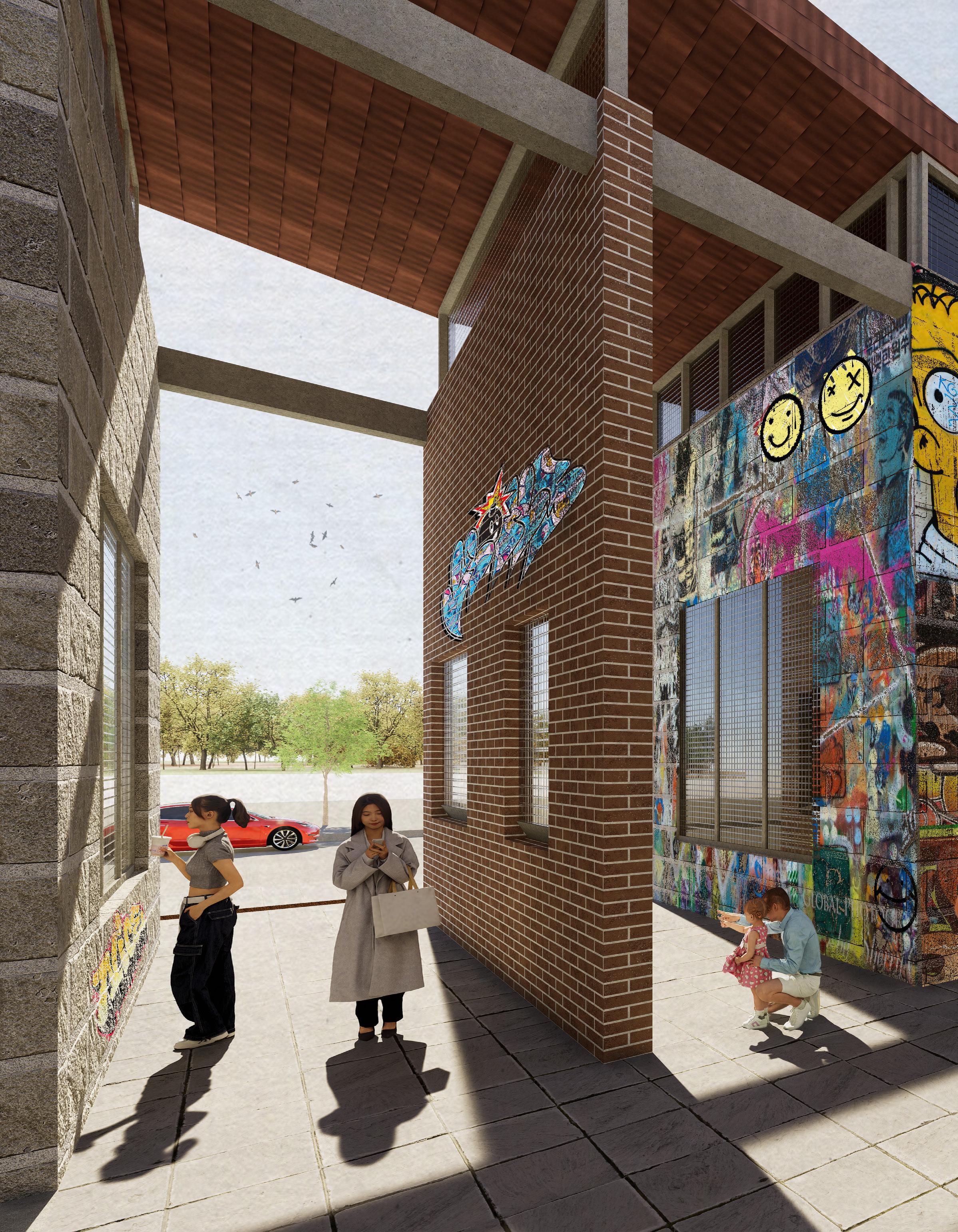
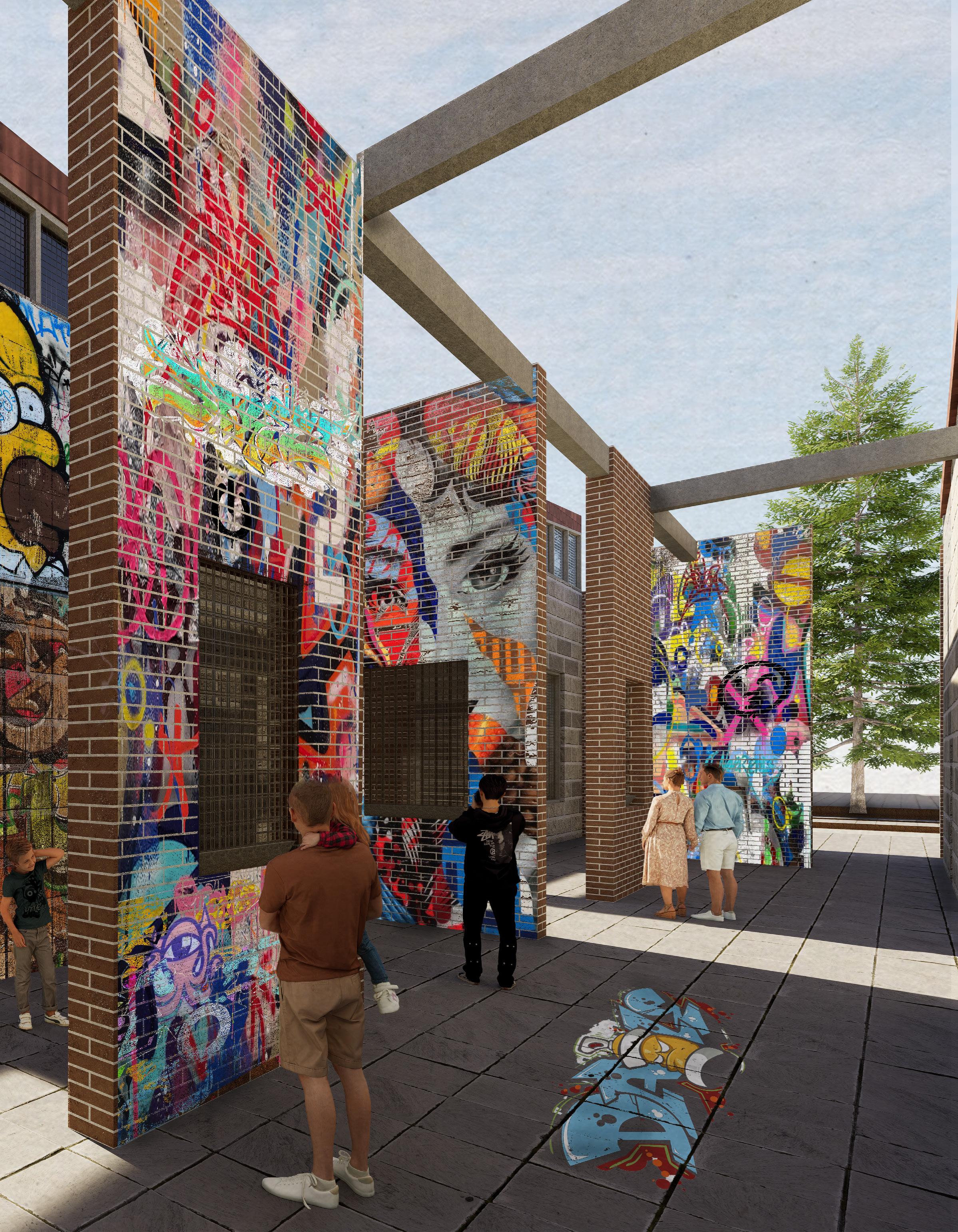
The foundation of the concept lies in the adaptive transformation of the original building’s walls, which have been artfully divided to yield a dynamic new structure. These partitions serve as blank canvases, inviting individuals from all backgrounds to enter this vibrant space and reveal their creativity.
The goal is to craft a space where stories are forged, etching narratives that serve both as a canvas for personal self-expression and a platform for thought-provoking, sensitive pieces that inspire conversations and reflections. This center aspires to become a beacon of artistic innovation, where every stroke, color, and design serves as a testament to the power of self-expression and a catalyst for meaningful dialogues, leaving an indelible mark on those who partake in its vibrant tapestry.
The Jesse Kregal Pathway consists of many types of street arts which was a source of inspiration for the Black Rock Urban Canvas center. This center curates various street art pieces, painting them along an alleyway where people gather for dining. However, the authenticity of commerical street arts are somewhat compromised, as they are through commissioned artists, detracting from the raw essence of street art culture.
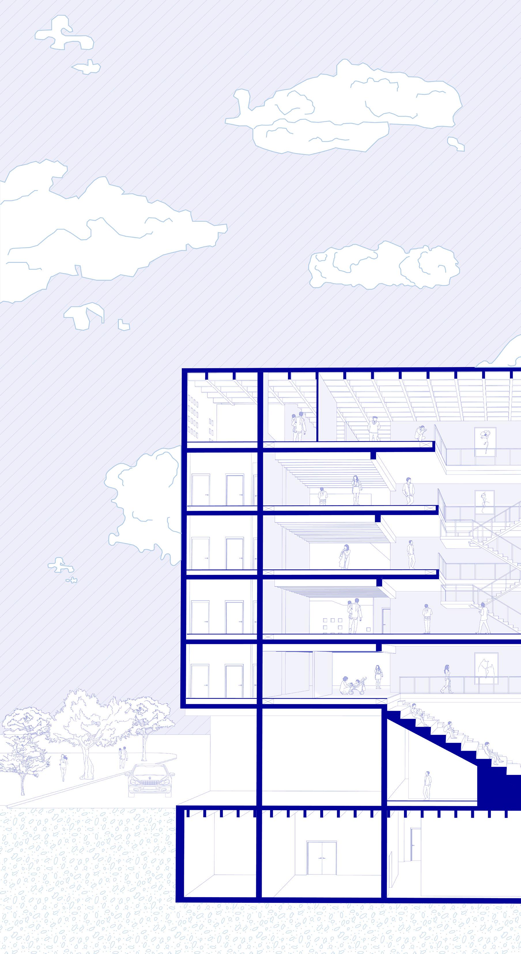
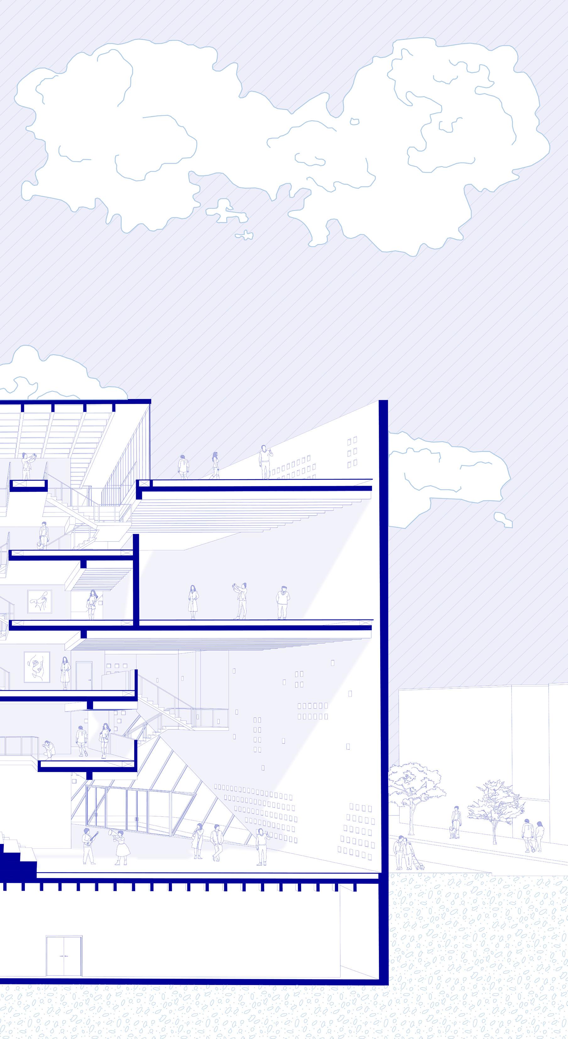
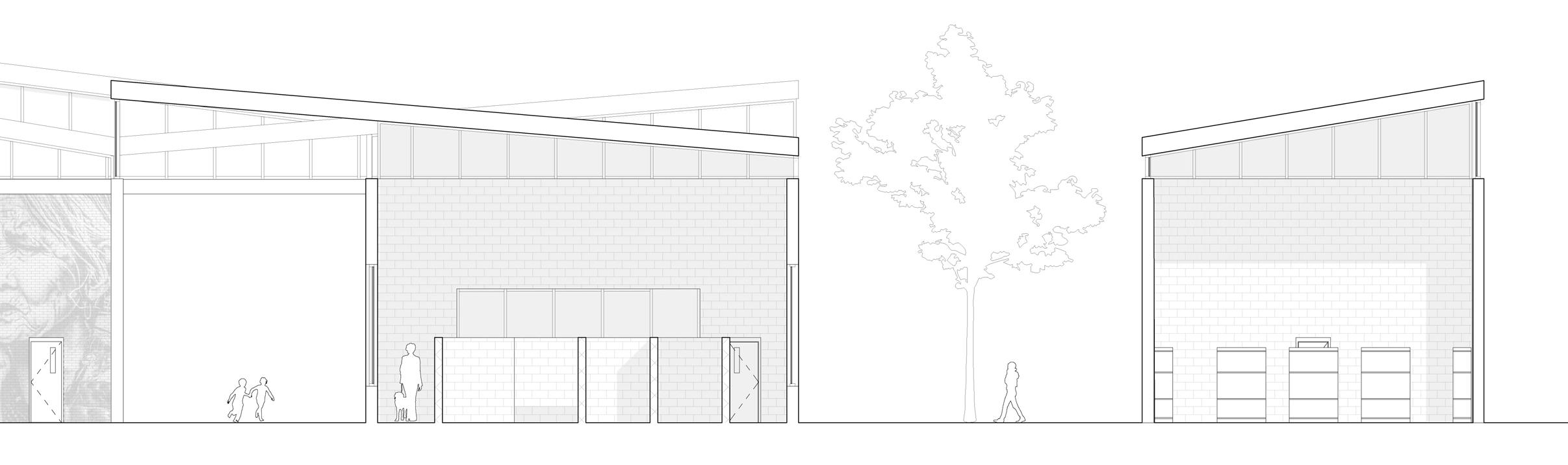
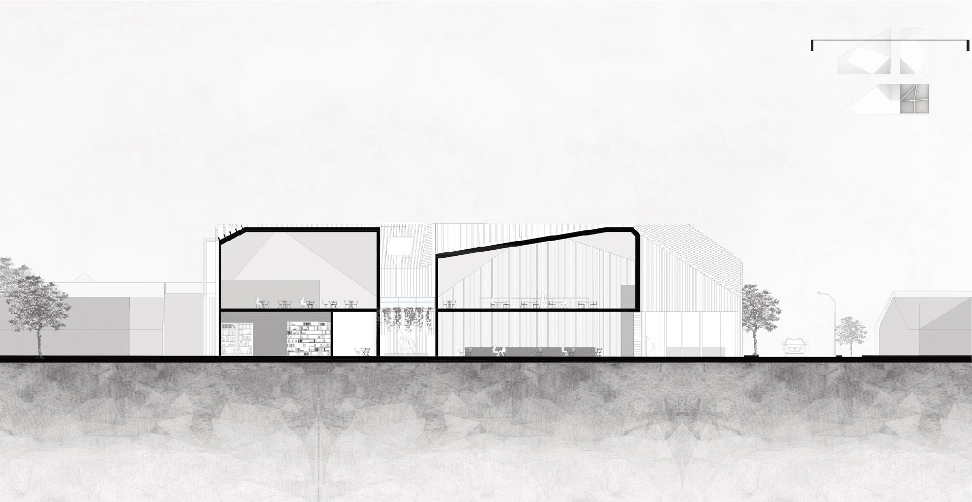
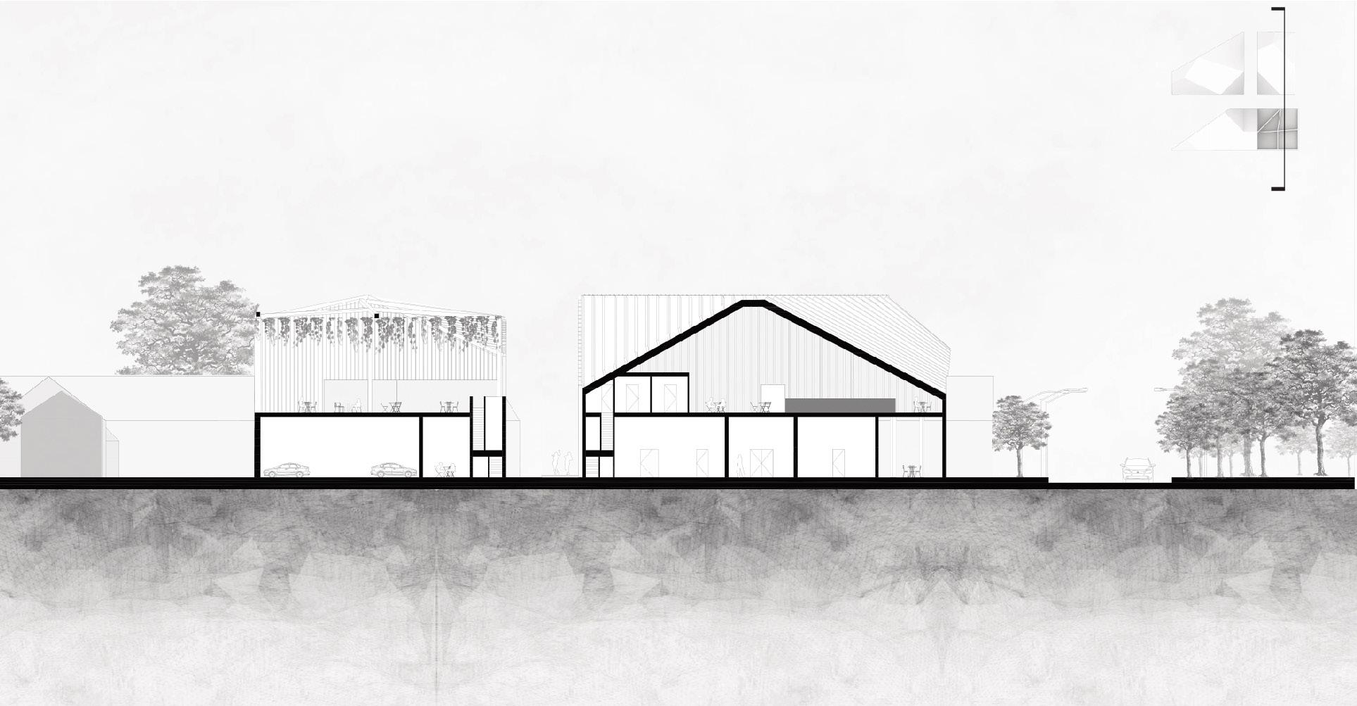
North Section
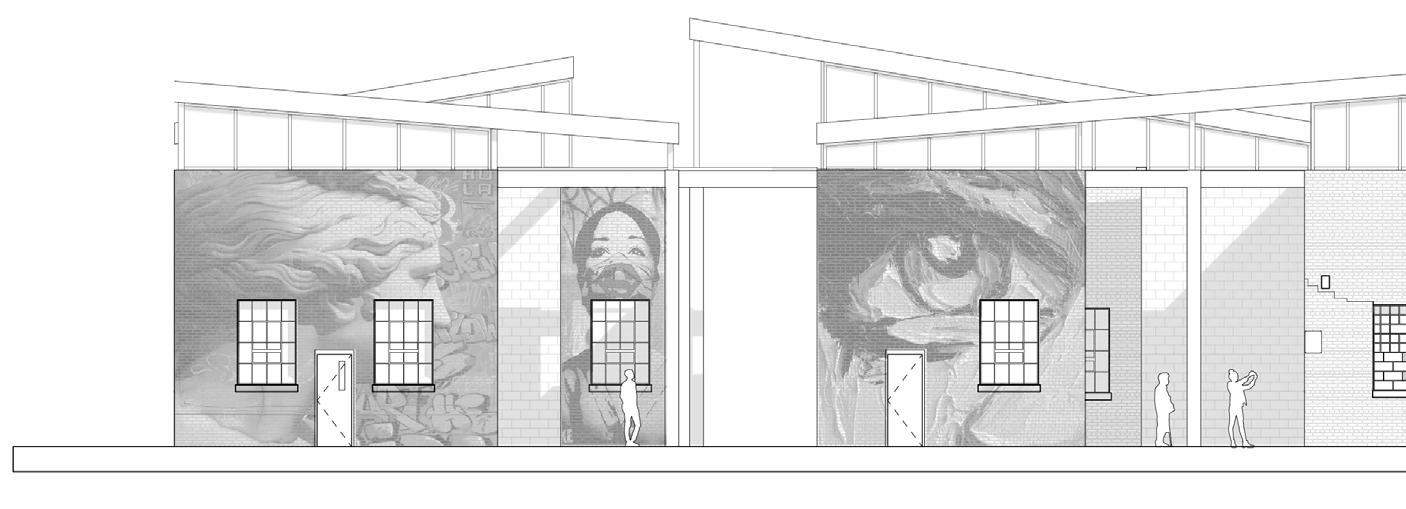
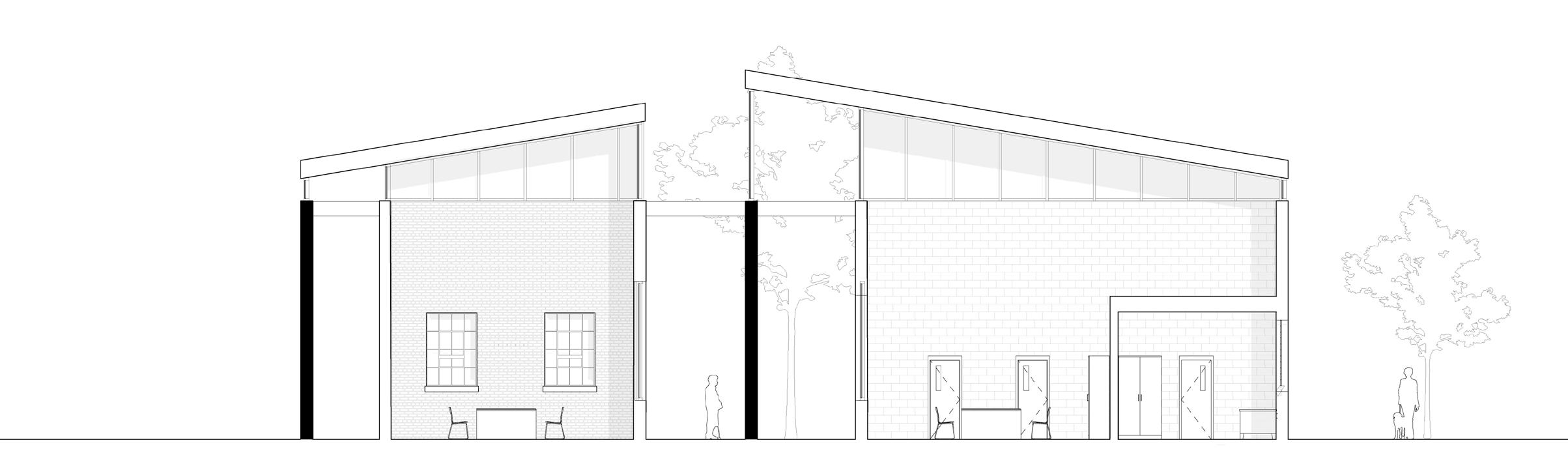
South Elevation
North Elevation
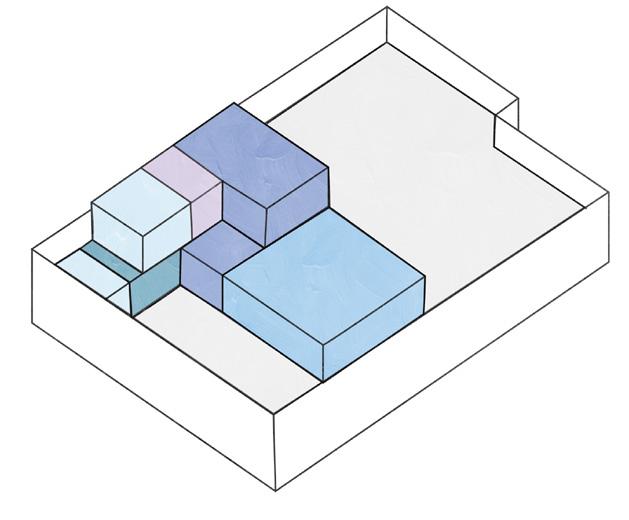
Schematic Design #1
The forefront of the design hosts a diverse range of programming, featuring an entrance compelled with contemplative graveyard area, complemented by a vibrant painting space situated on the second floor.
Schematic Design #2
This approach delves into an option where the program predominantly resides on the second floor, prompting individuals to ascend a ramp for an interactive experience with the space both above and below.
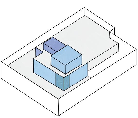
Schematic Design #3
This proposal explores an option in which the program extends beyond the original building, maintaining a layout and design that closely align with the choices made in design 1.
Breaking up the existing walls, opens up spaces for new structures but also creates a dynamic environment for the vibrant culture of street art. The broken walls also represent a break from the past while also starting a fresh canvas for the future. The walls that are divided and not connected with new walls will be supported by trusses from the original building, serving as structural support for the freestanding walls.
South Section
West Section
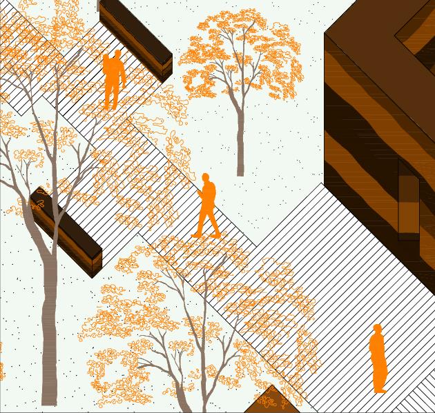
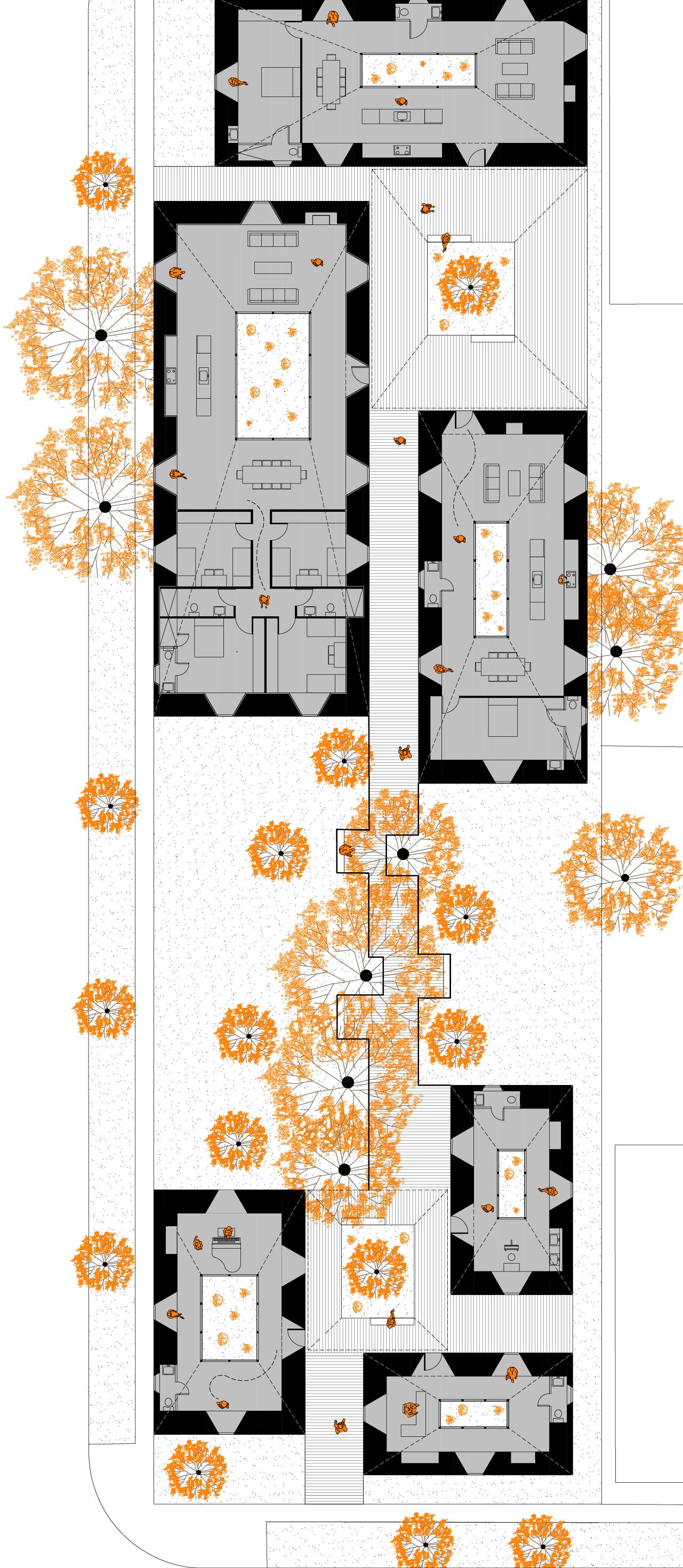
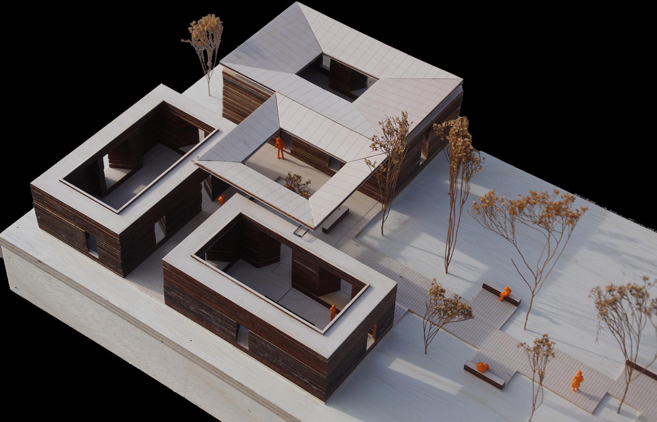
Inhabiting Mass: Residential Place
Studio Professor: Miguel Guitart | Fall 2022
Studio Partner: Lei Wang
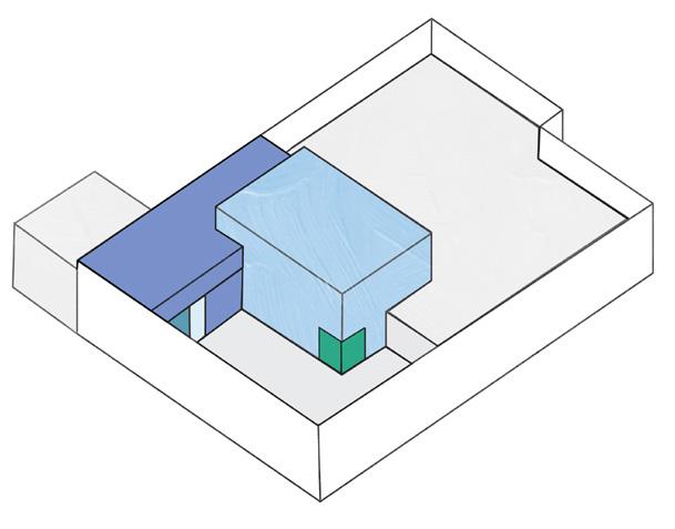
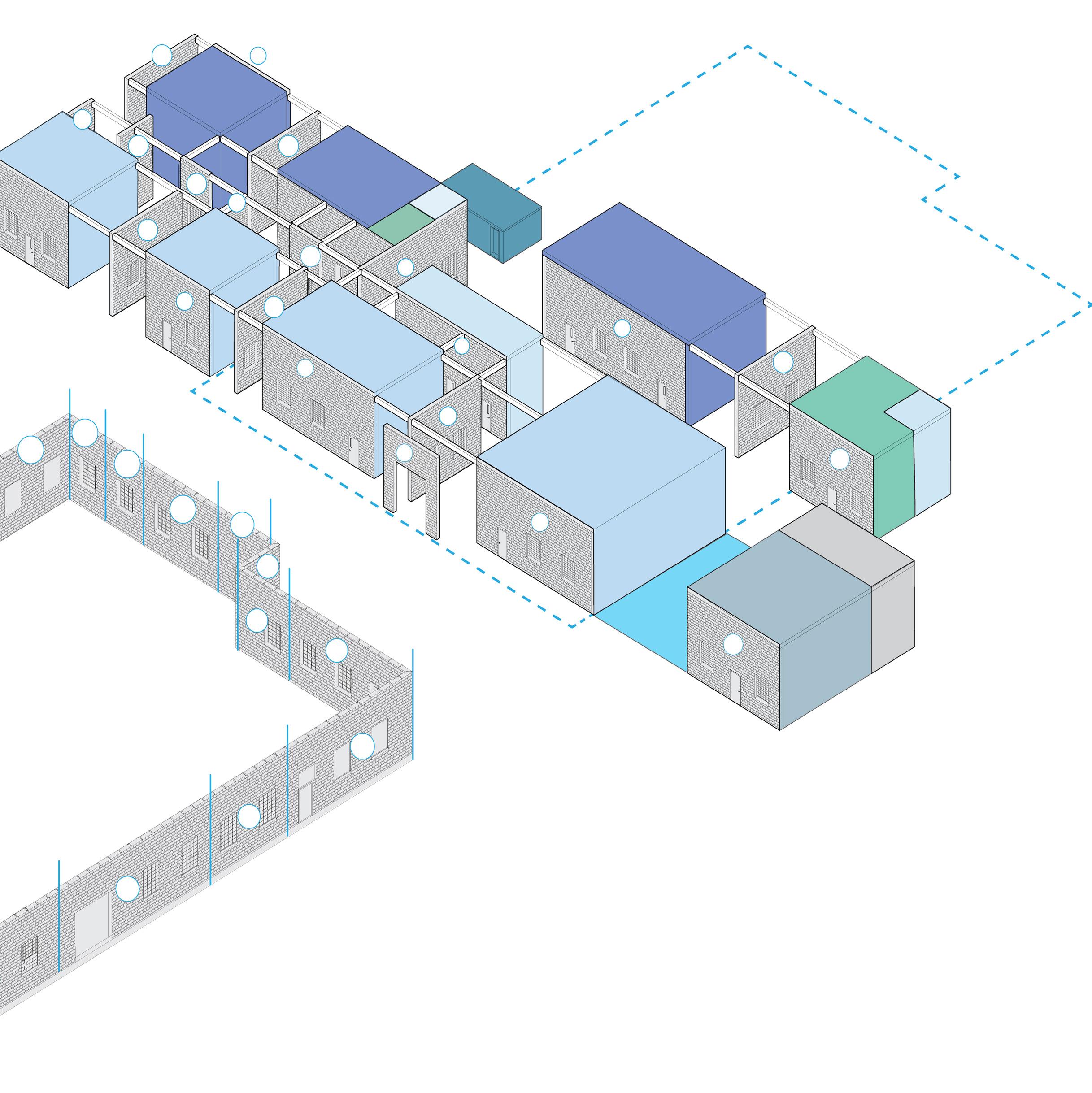
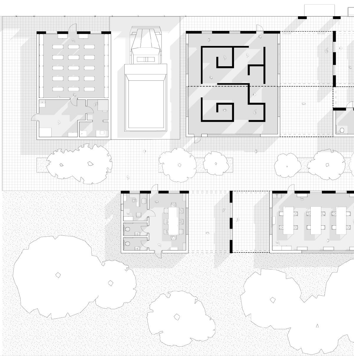
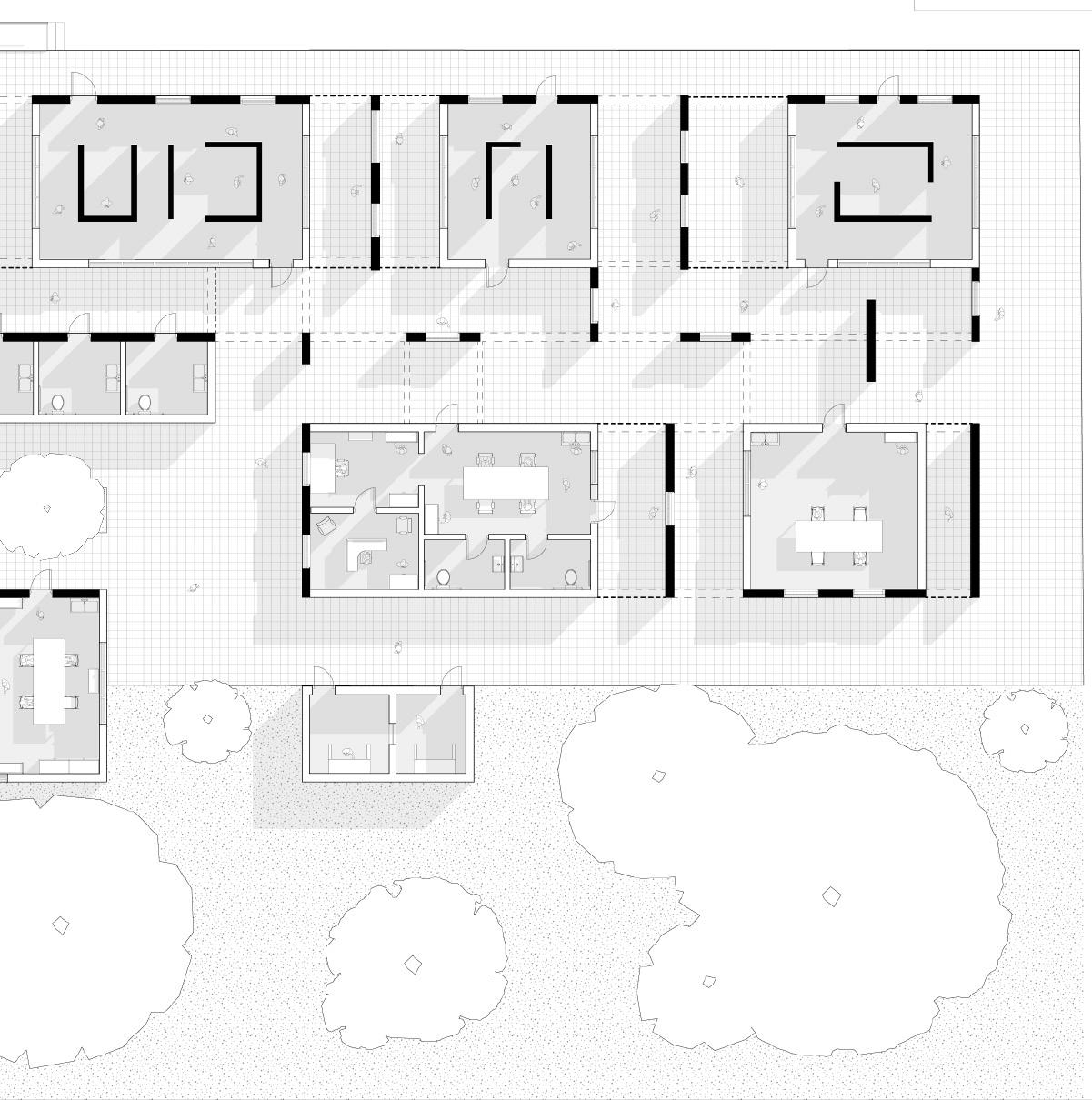
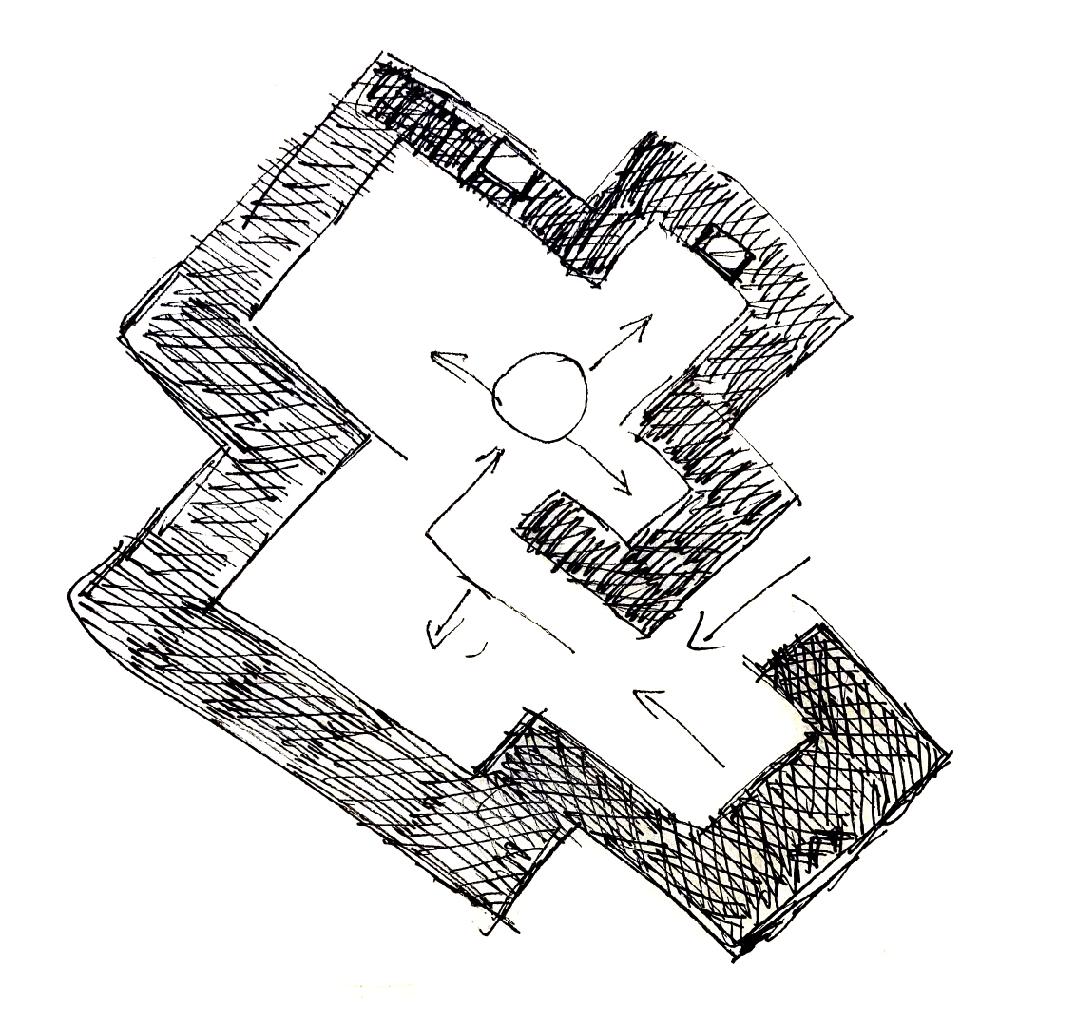
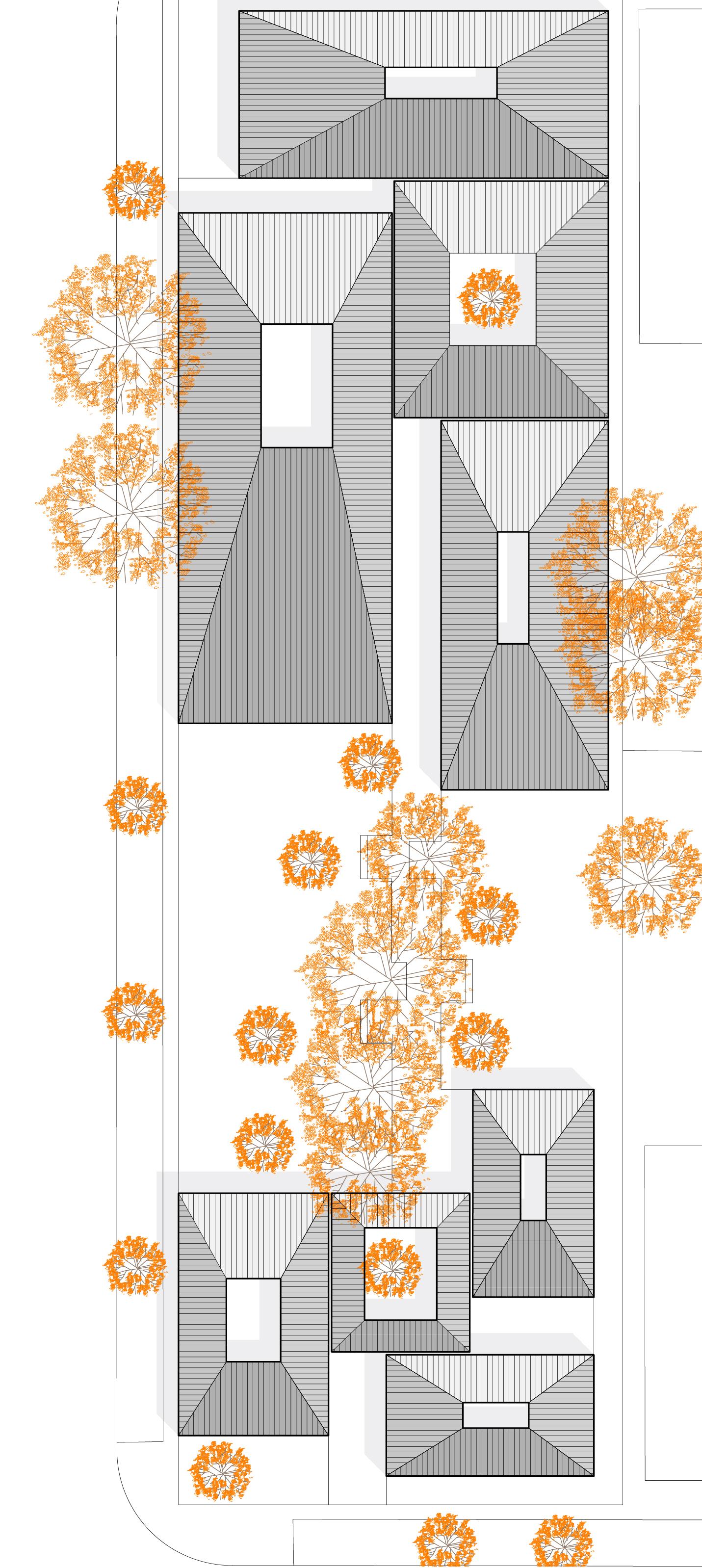
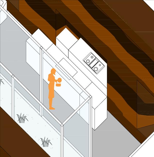
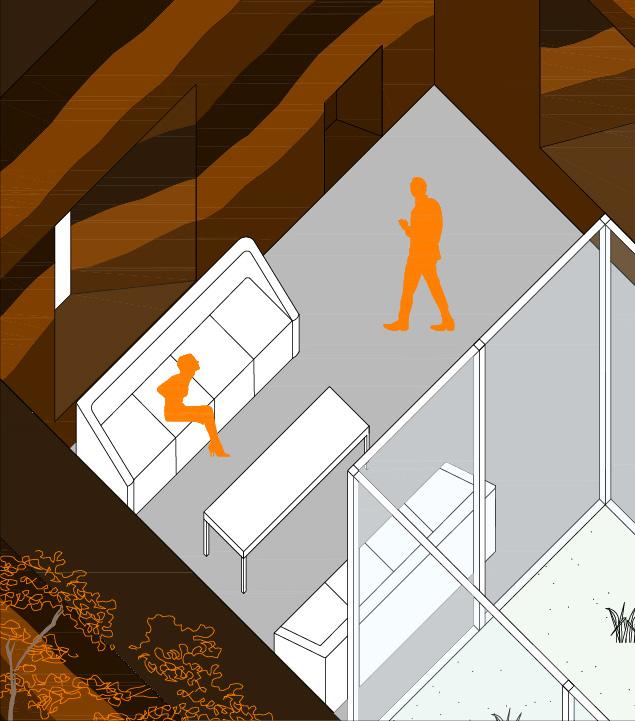
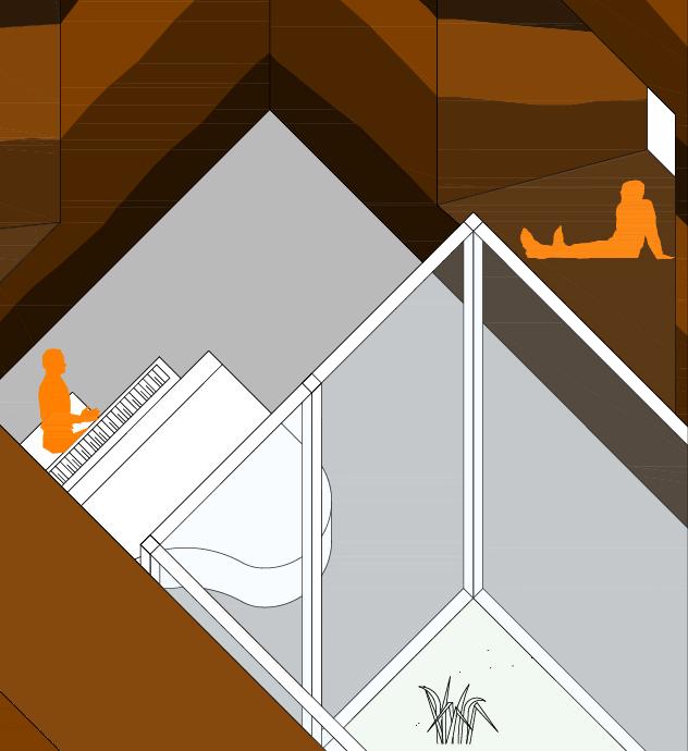
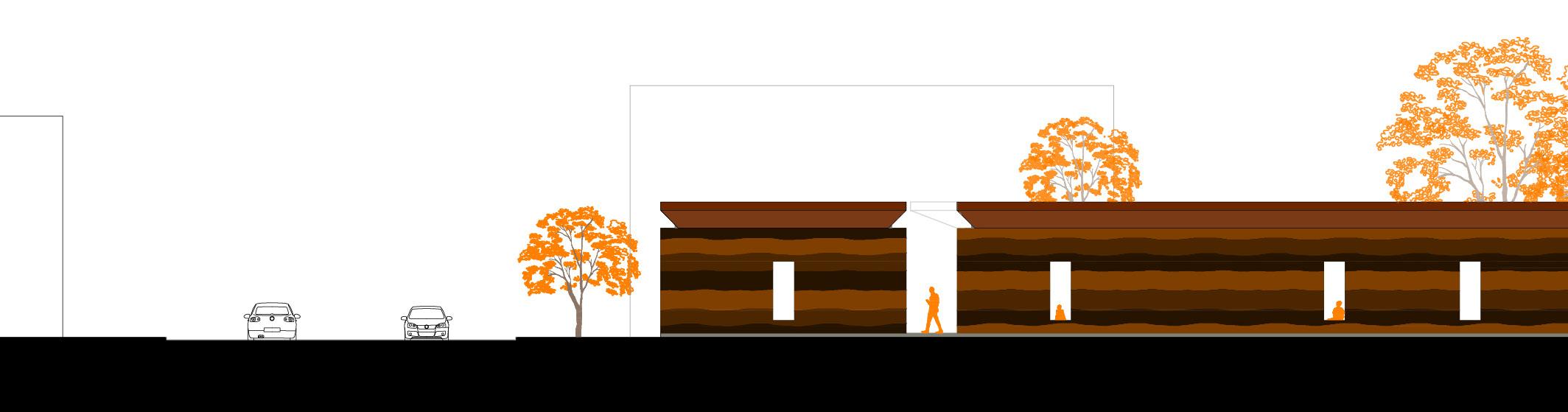
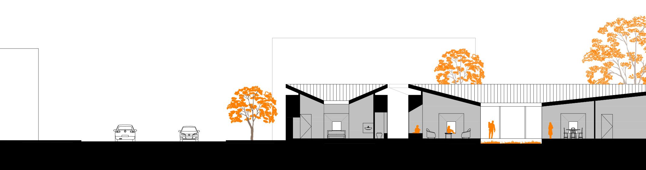
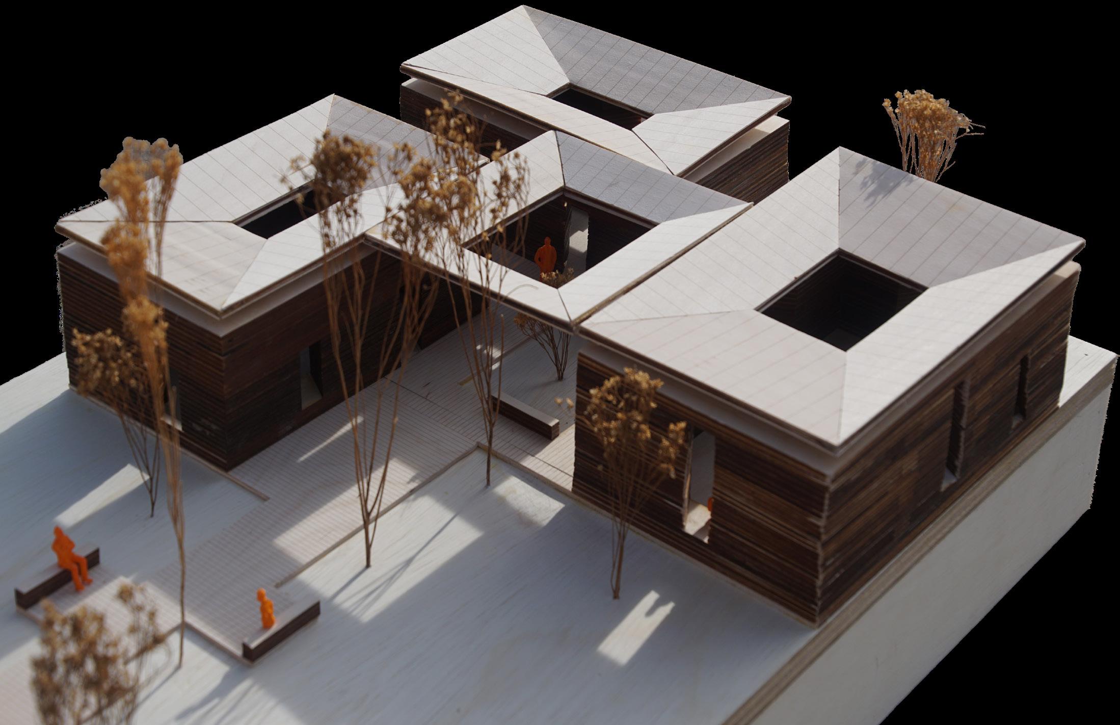
The project’s scope entails the creation of a residential space intended for three distinct households sharing a common lot. Each household is provided with individual studio units. The overarching objective of the “Inhabiting Mass” project is to engage in a comprehensive exploration of the ecological merits associated with rammed earth construction due to its low environmental impact, as it utilizes locally sourced, natural materials, reducing the carbon footprint associated with transportation. The main emphasis of the theme is to carve out voids within the masses for inhabitation. Furthermore, the intrinsic properties of impluvium together with rammed earth, facilitate the creation of an optimal indoor environment, particularly crucial during Buffalo’s harsh winter climate while simultaneously reducing heating and cooling energy requirements.
Sketch Concept | Circulation Through The Mass
Carved Out Mass
Inside The Mass
Courtyard Studio
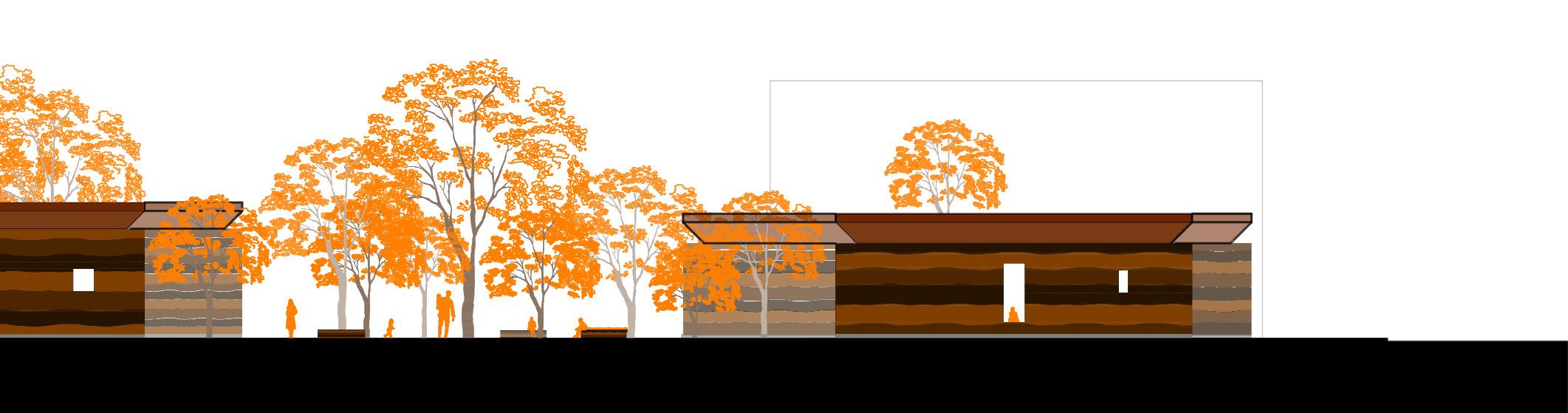
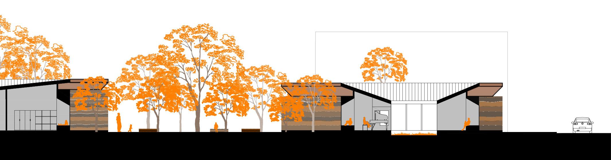
West Elevation
West Section
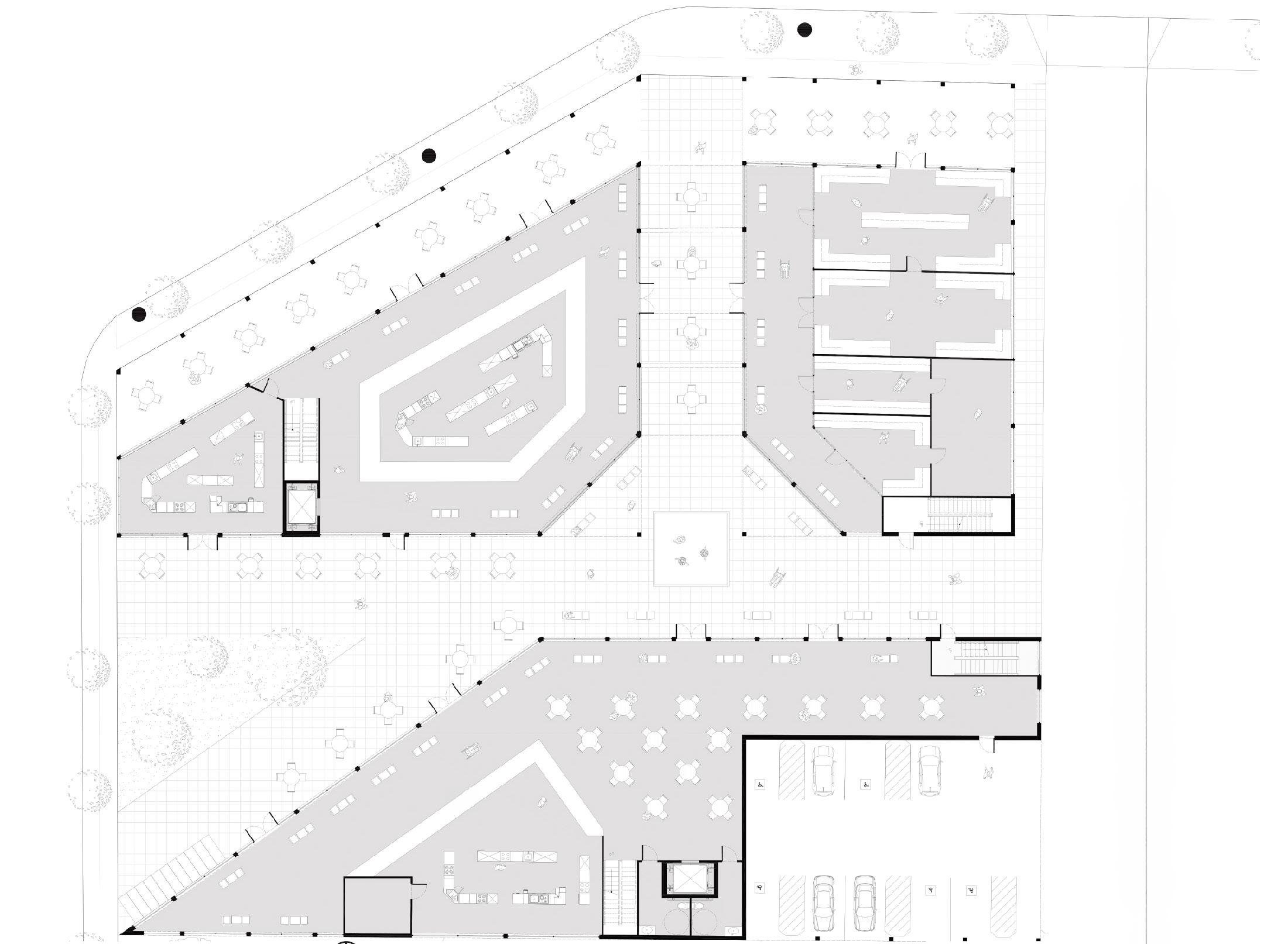
Mini-City Block: East Side Bazaar
Studio Professor: Maia Peck | Spring 2023
The Buffalo urban grid is a unique and complex system that has been shaped by a variety of historical, social, and economic factors. It is a testament to the evolution of urban planning and design over time.
Located within the Broadway Fillmore neighborhood, this project demonstrates that the city’s urban grid is a result of both positive and negative effects of its growing population. From the creation of Olmsted’s famous Parkway system that formed an emerald necklace around the city’s core, to the destruction of the emerald necklace with the creation of the Kensington Expressway has resulted in the demolition of the system and the displacement of thousands of residents.
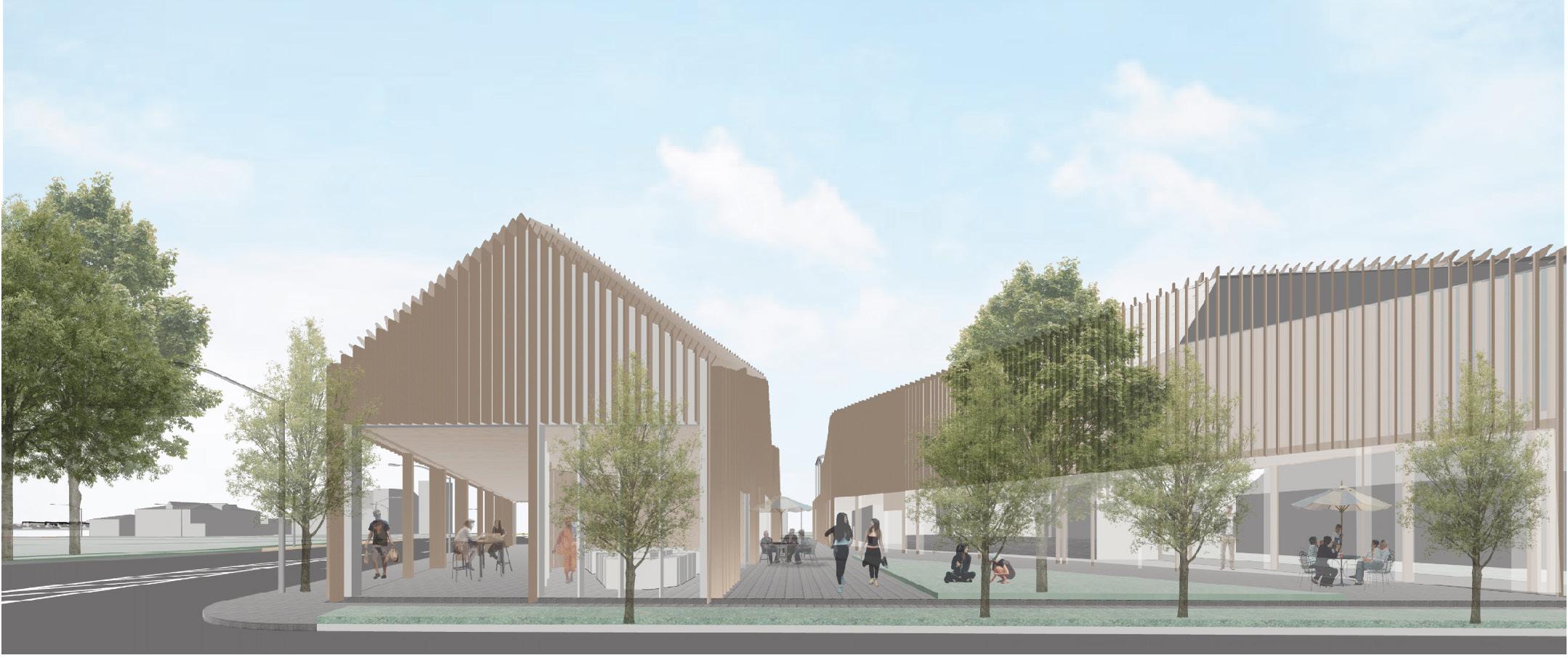
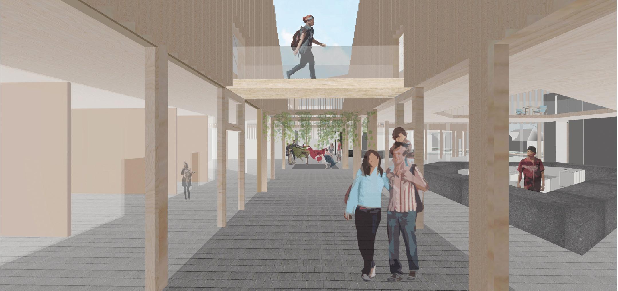
The Mini-City Block Bazaar is the result of the many changes that have happened on top of the urban grid inside the Broadway Fillmore neighborhood. It is a miniature city that seeks to exemplify a new architecture that will breathe new life into the urban fabric by incorporating street designs and providing an enchanting pedestrian experience. It will ultimately act as a replica of a history that is both the past but also the present.
View of East Side
View of Main Entrance
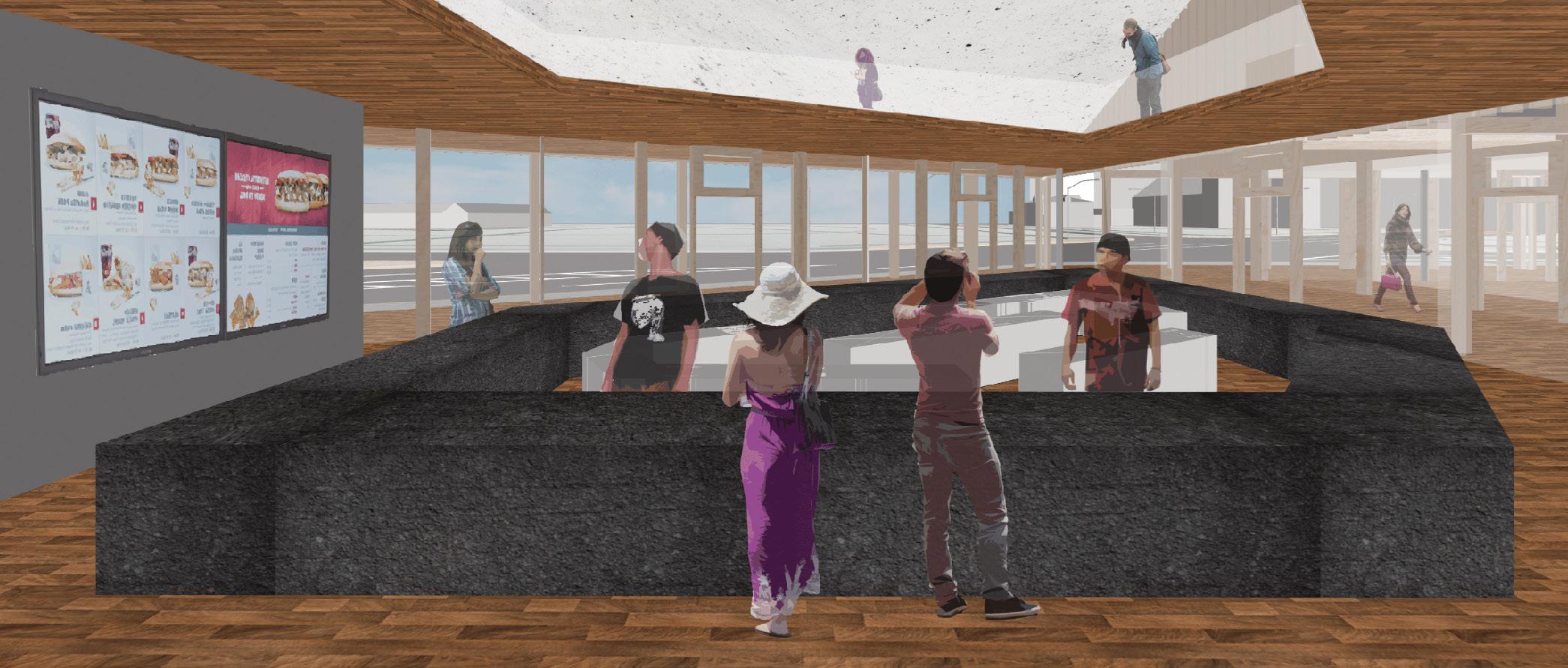
View of Food Vendors
North Section
Flagship Store and Headquarters in London
Architects: Squire and Partners
Professor: Annette Lecuyer | Spring 2024
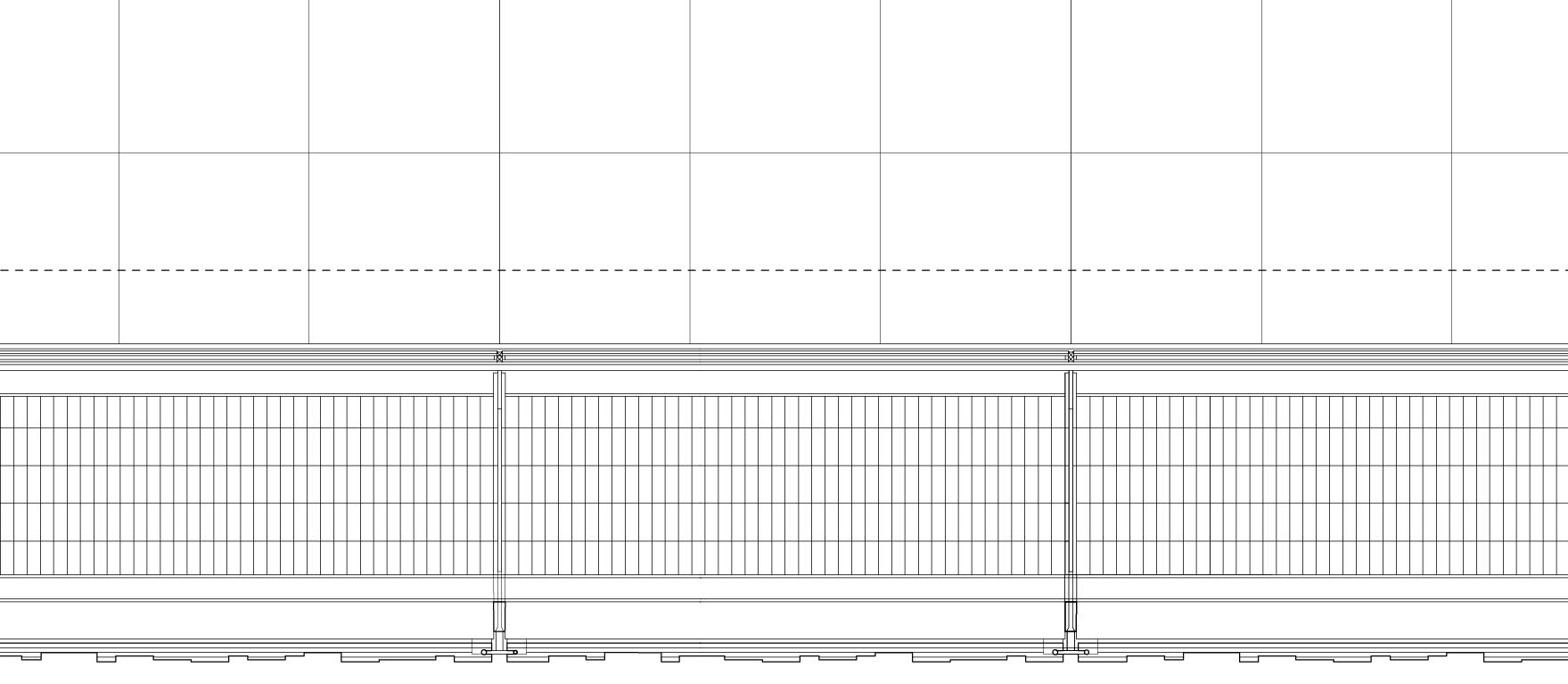
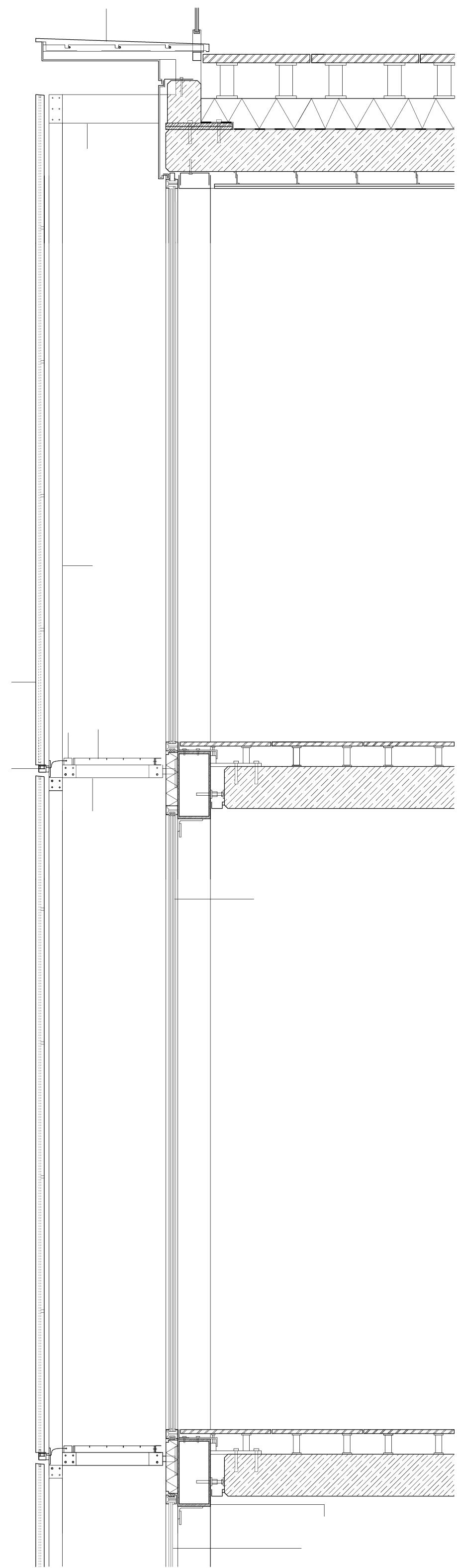
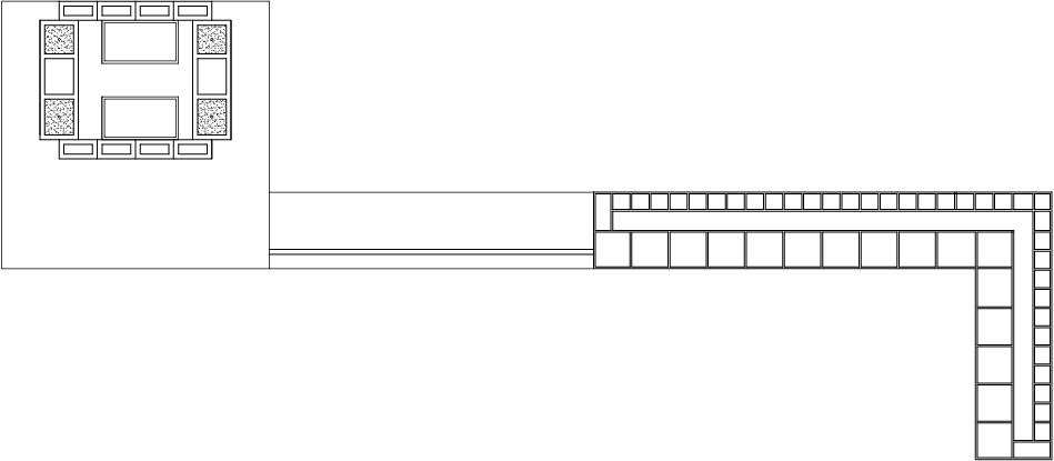
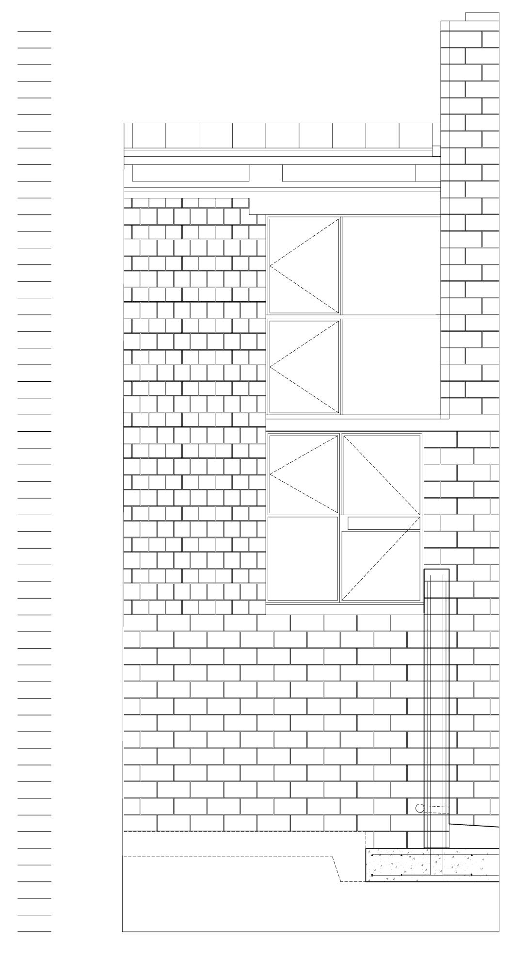
Façade Specification Notes
01. 30–50 mm acrylic panel
02. 42/42 mm aluminium section cover plate A.Brushed, shrouding LED fitting
03. 40/70 mm bright mild steel structural cable tray
04. 30/80 mm steel RHS post, powder-coated
05. 30/80 mm steel flat, powder-coated
06. 30/170 mm steel flat cantilever beam
07. Maintenance deck: 40 mm steel grating, powder-coated
A. Aluminium coping fixed back to concrete upstand
B. Lateral close of facade cavity: toughened glass panel
08. Door: 2≈ 8 mm toughened glass bonded to bright mild steel frame
09. Retail facade: 2≈ 11 mm laminated safety glass
10. 200/400/5 mm steel beam
11. SSG curtain wall system
12. 2≈ 6 mm laminated safety glass + 16 mm cavity +
13. 6 mm toughened glass
14. 200/80 steel RHS post (at door only)
15. Ø 7 mm stainless-steel lateral loading rods mechanically
Façade Elevation
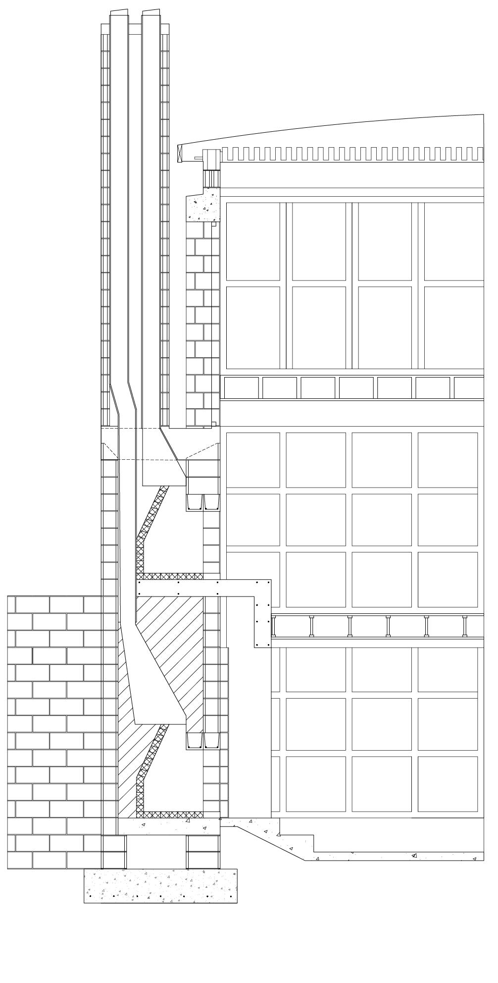
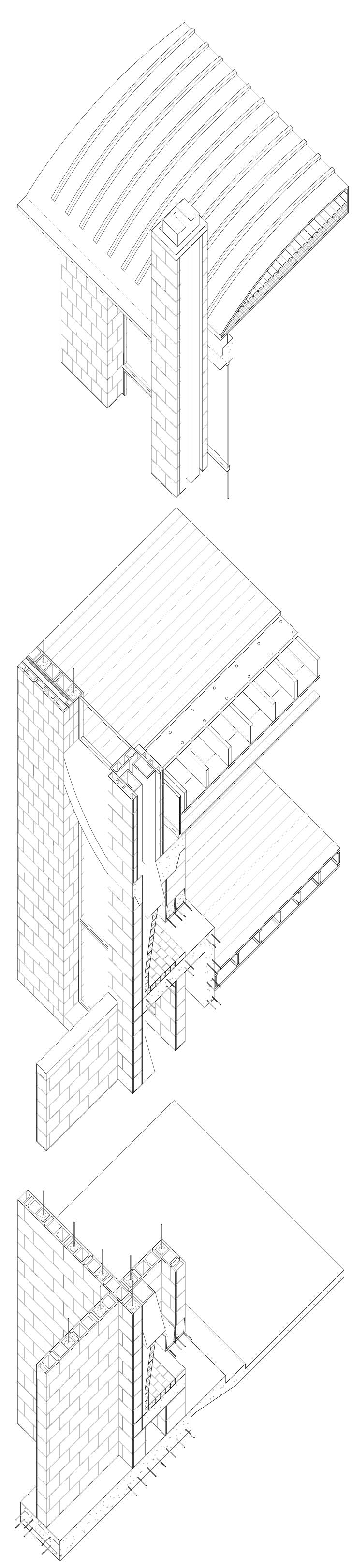
Façade Specification Notes
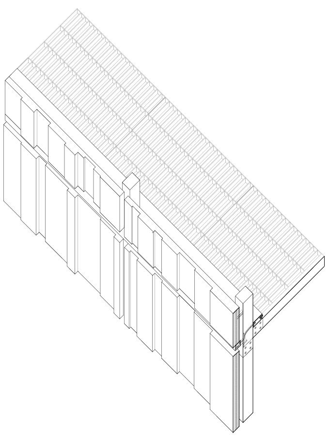
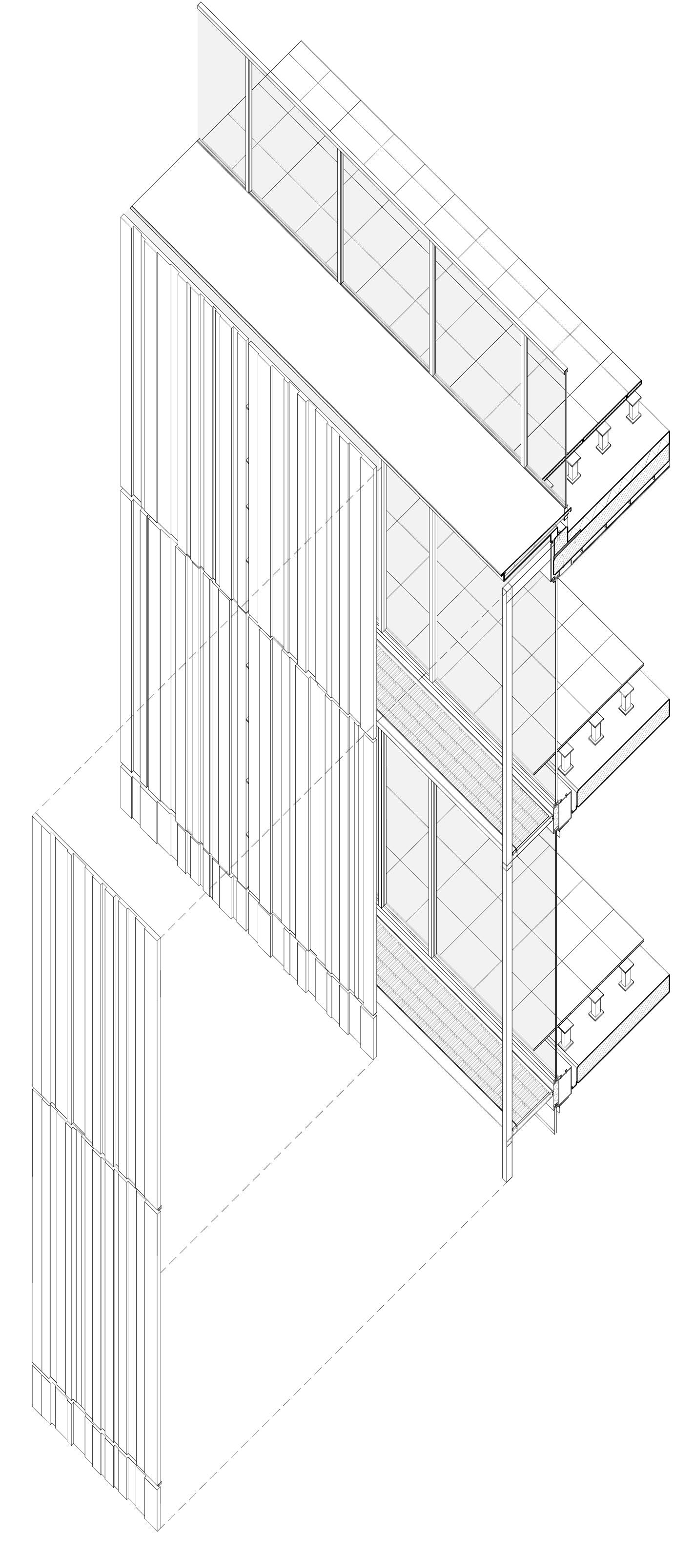
01. Roof
Raised roof cladding: 75 mm (3 inch) thick open jointed precast concrete pavers on pedestals and 200 mm (8 inch) void for drainage. 200 mm (8 inch) rigid insulation. Waterproof membrane.
Parapet: Precast concrete upstand, aluminum overhanging coping fixed back to concrete upstand, and frameless glass balustrade.
02. Typical Floor
Raised floor: 50 mm (2 inch) thick precast concrete panels on pedestals,150 mm (6 inch) void for services distribution, 250 mm (10 inch) site cast reinforced concrete slab, 200 x 400 x 5 mm (8 x 16 x 1/4 inch) rectangular hollow section steel beam.
2 layers x 6mm (1/4 inch) thick laminated safety glass +6 mm (1/4 inch) cavity + 6mm (1/4 inch) toughened glass with clear sealant joints: and 200 x 800 mm (8 x 3-1/4 inch) rectangulat hollow section vertical posts at doors.
Metal clad insulated spandrel panels to cover slabs.
04. Exterior Envelope (Outer Layer)
4a Structure:
30 x 170 mm (1-1/4 x 6-3/4 inch) steel flat cantilever beam at roof, 30 x 80 mm (1-1/4 x 3-1/4 inch) steel flat beam at typical floors, powder coated, 30 x 80 mm (1-1/4 x 3-1/4 inch) rectangular hollow section post, powder coated, 7 mm (1/4 inch) diameter stainless steel lateral loading rods, 4 per floor, mechanically restrained back to post. Steel pin to loading rods, milled.
4b Maintenance Catwalk:
40 mm (1-1/2 inch) steel grating, powder coated, 40 x 70 mm (1-1/2 x 2-3/4 inch) bright mild steel structural cable tray.
4c Cladding:
30-50mm (1-1/4 to 2 inch) thick acrylic panel secured with T-shaped recessed steel brackets, 42 x 42 mm (1-3/4 x 1-3/4 inch) brushed aluminum cover plate/ shroud to individually controllable and programmable LED fittings.
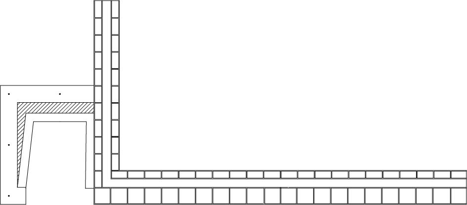
Chimney Specification Notes
01. Foundation for House Wall
30-inch wide x 12-inch deep site cast concrete strip footing with 3- #5 rebar long.
02. Foundation at Fireplace
12-inch deep site cast concrete pad footing to extend 6 inches beyond the outer face of masonry, with 10#5 rebar north/south bottom and 8- #5 rebar east/ west bottom.
03. Foundation at Retaining Wall
60-inch wide x 12-inch deep site cast concrete strip footing with 4-#5 rebar long top and bottom, and #4 at 12 inches OC short.
04. External House Wall Below Grade
8 x 16 x 16 single wythe CMU with #6 vertical rebar grouted solid at 24 inches OC outer face and 48 inches OC inner face, and horizontal joint reinforcement at 8 inches OC.
05. External House Wall Above Grade
8 x 16 x 8 CMU inner wythe with 3-#5 vertical rebar grouted solid at corners, each side of large openings, and 48 inches OC; horizontal joint reinforcement at 16 inches OC.
06. Retaining wall
8 x 16 x 2 CMU single wythe with #5 vertical rebar at 24 inches OC grouted solid; horizontal joint reinforcement at 8 inches OC.
07. Fireplace at Lower Ground and Upper Ground Levels
8 X 16 x 8 CMU single wythe with 1-#5 vertical rebar grouted solid at corners and midpoints of walls; horizontal joint reinforcement at 16 inches OC.
8-inch site cast concrete L-shaped hearth with #4 rebar at 16 inches OC on top and bottom in the slab, and #4 rebar at 16 inches OC on both faces of the wall.
8-inch thick site cast concrete cap at living room level.
08. Fireplace Chimney
8 x 16 x 4 CMU single wythe with vertical rebar grouted solid at corners and horizontal joint reinforcement.
8 inch thick site cast concrete cap.
09. Living Room Floor
2 x 10 solid web wood joists/TJIs at 16 inches OC with batt insulation between.
2 x 6 tongue and groove wood deck
10. Loft Floor
W12 x 14 steel beam
3 x 10 wood joists at 16 inches OC
2 x 6 tongue and groove wood deck
11. Roof
Flitch beam: 4-2 x 10 wood joists and 3/8 inch steel plate, stagger bolted.
2 x 10 LVL (laminated veneer lumber) joists at 16 inches OC.