
PORT FOLIO
Ran (Bonnie) Li

Ran (Bonnie) Li
Email: bonnie11123266@gmail.com
Mobile: (437)-970-8823
Masters level architecture student with 5 years of architecture-related experience in a professional environment, with experience working in both small and large team environments focusing on Preliminary design to Schematic Design to Construction Design.
Technical Proficiency: Rhino, Revit, AutoCAD, Sketchup, Adobe suit, Grasshopper, ZBrush, Discover, Fusion 360
Education
University of Toronto, Master of Architecture
University of Melbourne, Bachelor of Environments, Major in Architecture
Study Abroad Program: Architectural Association School of Architecture & Tsinghua University
Work Experience
2020-2023
2016-2018
HEADQUARTERS
Zaha Hadid Architects
Student Architect, Farrow Partners Inc Architects, Toronto Feb 2022 –Present
o Projects: large-scale Medical Centre project, four school projects and one golf club
Graduate Research Assistant, University of Toronto Sept 2022 – Present
o Supervisor: Pina Petricone
Teaching Assistant, University of Toronto, Toronto May 2022 – Present
o ARC495Y1F, Supervisor: Pina Petricone; ARC1022, Supervisor: Maria Yablonina
Architectural Intern, Zaha Hadid Architects, Beijing May 2021 - August 2021
o Projects: Tower C Shenzhen Bay Super Headquarters, Oppo Shenzhen Headquarters
Developed the Mixed-Use Revit Template and created multiple typical building detail; Supporting submission on Schematic Design and Design Development, Coordination Set and Tender Set; Coordinated with all consultants to compile the submission documents
Junior Interior Architect, 2pi rdesign, Toronto
Nov 2019 – Aug 2020
o Projects: Beijing Yin Tai office Tower, Park Hyatt Beijing Restaurant, Shangri La Hotel Zhengzhou, Hua Run Kunming Office Tower, Kapok Hotel
Architectural Intern, Kengo Kuma & Associates, Beijing Feb 2019 – Apr 2019
o Projects: Changdao Creative Center of Economy Culture Art Center, Hai Kou Tourist Center, Zhu Ye Qing Tea Scenic Park
Architectural Intern, Archi Solution, Beijing
July 2018
o Advocated for data-driven architecture, with experience in creating and sorting databases of building performance parameters
Student Intern, Collard Clarke Jackson, Canberra
June 2015
BLOOD-COOLING GLOVE
University of Melbourne
1. Zaha Hadid


Architects
Beijing, Team Work(6), 2021
OPPO HEADQUARTERS
Oppo Telecommunication, 185,000m2
TOWER C AT SHENZHEN


BAY SUPER HEADQUARTERS BASE
Shenzhen Bay Super Base Construction
Headquarters Office
GFA: 440,000m2
Site Area: 36268m2
2. KKAA WORKS
Kengo Kuma & Associates, Beijing
Team Work(3)
CHENGDU CONTEMPORARY ART CENTRE

GFA:60,000m2
Site Area: 60,465m2(West)+29,453m2

FAR: ~0.67


3. KKAA WORKS
Kengo Kuma & Associates, Beijing Team Work(3)


HAIKOU TOURIST CENTER

GFA:1403m2
Site Area: 16295m2
FAR: ~8.61


4. THE HYBRID CITY
June-Aug 2020
Sudbury 2050 City Urban Plan


Team: Jie Liu, Kai tian, Ran Li
DESIGN PHILOSOPHY
The Hybrid City starts from the keywords "Diversification in Urban Speed", which divides into high (Highspeed Train/Commuting Tube), middle (Freight Train/Tram), slow (Park Path/Sky walkway/Bath Path/Urban Sidewalk) and zero (Solar Energy/Wind Energy/Stormwater system). At the same time, the city will act as a symbol of integration of children, young adults, and older people.
Centre Park green roof and the upgrade public transport systems provide an innovative solution Sudbury Train Station.The station will become one of the strategic points of Canadian’s high-speed rail route between Sudbury, Montreal and Toronto, and a symbol of economic development in the country. The rail line will connect urban areas and business zones adjacent to economic centres.
The resulting transport system creates a series of urban flows, from the high-speed rail located of the middle level, to the medium pace freight track on the ground, finally to the slow pace of the central park. Elevated above the road network, the centre park also allows for easy access between adjacent plots.


PROPOSED CITY SPACE
SPEED HIERARCHY
PROPOSED TRAFFIC SYSTEM

PROPOSED SKY GARDEN
PROPOSED CENTRAL PARK


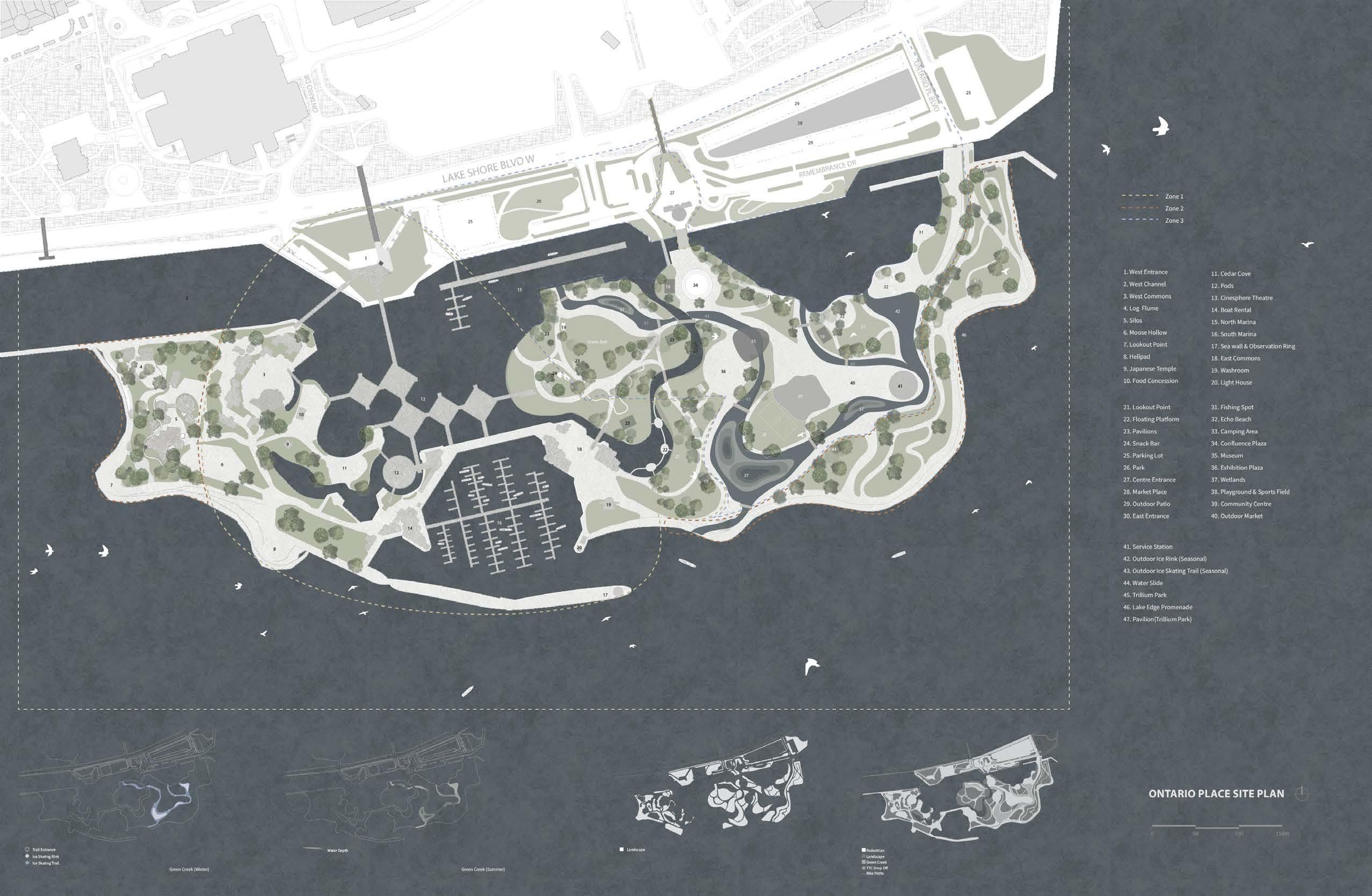
5. FUTURE OF ONTARIO PLACE
2021 December, 1 month
Team: Elva Hu, Flora Chan, Ran Li
Site: Ontario Place, Toronto, Canada
Software: Rhino, Grasshopper, Photoshop
GREEN CREEK
The Ontario Place is located on three artificial landscape islands just off shore in Lake Ontario. It is an entertainment venue, event venue, and park in Toronto.
Living up to the suggestiveness of its name, Green Creek is an innovative scheme to reinstate natural habitats in the city. The design encourages biodiversity and protects the environment. The creek will enable us to transition to an abundant and diversified urban nature, connected and linked to human beings.
We are creating a creek that will enable the transition from a sterile lawn to a diversified landscape park, connected to all living beings and it will attract birds, pollinating insects, and small animals.

The new site plan consists of reintegrating wildlife and natural habitats in the urban territory of Toronto, more than 50% of which is now a sea of aggregate occupied by commercial activities.
Due to the effect by Covid-19 epidemic, the future city should focus on improving liveability and resilience to try to avoid building concentrated areas, instead of opening space decentralized areas.
Stairs and slopes bridge the interaction between ecology and human activities

BIODIVERSITY
The goal of the Green Creek is to introduce a new habitat for various fauna and flora and establish a system that coexists with the city.
The Floating Platform encourages people to have a closer look to the eco-environment
HUMAN ACTIVIES
SUMMER TIME
Birds
WINTER TIME
Trees
Shrubs
Herbs
Water Fowls
Aquatic Ecology
In the summertime, the creek is a green and lively eco-park for the citizens, fauna, and flora. All the livings are gathered and connected in the Green Creek.
In the wintertime, the creek will transform into a playground and leisure space for ice skating, snowboarding, and other winter activities.
GREEN BELT ECOSYSTEMStair Seatings
(Recycled Granite)
Low-E Glazing
Observation Deck
(Recycled Timber Planks) Green Space Shading Device
Glass Fiber-reinforced Polyester Facade
ICE SKATING ON CREEK (WINTER)
During the winter, Green Creek will be the largest skating rink in Toronto.
Trail Entrance
Ice Skating Trail
Ice Skating Rink
AQUATIC CONDITION (SUMMER)
The wetlands will be built at different elevations, which means even with variations in water levels, there will always be room available for fishes, birds, and other wildlife to find food and shelter to keeps sustain the ecosystem.
Water Depth Wetlands

6. THE NEW SEMI-PUBLIC REALM

University of Toronto, Comprehensive Studio, 2022
Site: Lower Manhattan, US
Partner: Chuan He Instructor: Brigitte Shim
Our project demonstrates how urban life and activity can flourish in a new privately-owned public roofscape that is accessible by the local community. In response to social and climate issues such as pandemics and flooding, rooftops can serve as a new form of public realm. We used Cross-Laminated Timber (CLT) structure as the primary structure. Material waste will be further reduced by recycling the temporary support structures. Prefabrication shortens construction time, saves energy, and reduces embodied carbon.


In contrast to traditional buildings, our project moves all mechanical systems underground. This allows us to fully use the roof as a new public space. Adding a canopy ensures that space can be used year-round. During cold months, the canopy and glazing act as a greenhouse. The sunlight heats the semi-conditioned space, and in the summer, shading will block excessive sunlight.
 Glass Panel
Transparent PV Panel
Glass Panel
Transparent PV Panel

7. BLOOD-COOLING GLOVE


Academic, University of Melbourne, 2017
Semester-long, Tutor: Dan Schulz
Computation on architectural design "Body of the future"
The scenario for this studio is 'body of the future'. Designed a prosthetic/ wearable architecture that had an inside and an outside. This prosthetic augment a part of the body (arm). In order to find a new boundry of the body.


How does the body function under normal thermal circumstances?


As a steady-state situation, the heat produced by the body is balanced by the heat lost to the environment.
An equation for the body heat balance can be written as: M
“where M is the rate at which thermal energy is produced by the body through metabolic processes, W is the rate of work produced by or on the body, R is the rate of radiant heat exchange with the surroundings, C is the rate of convective heat exchange with the surroundings, E is the rate of heat loss due to evaporation of body water, and S is the rate of heat storage in the body. Numerous studies have confirmed that in many species, an absorbed dose of microwave energy equivalent to the resting metabolic heat production, elevates the deep body temperature of the animal by 1 degree or more. S should ideally be close to zero in order to prevent body temperature changes.”

What are the means of heat loss from the body?

Radiation, convection, and evaporation are ways of heat loss that are directly related to the surface area of the human’s body. A example: wind makes a hot day feel much cooler due to heat is removed from human body more efficiently.
How much heat does the body produce?

According to the Basal Metabolic Rate (BMR), the heat production of a human in a thermoneutral environment (33°C or 91°F) at rest mentally and physically more than 12 hours after the last meal.
Reference:
7-10 Polk, Charles and Elliot Postow, ed. Handbook of Biological Effects of Electromagnetic Fields. 2nd ed. CRC Press: Boca Raton, FL, 1995.
ALTERNATIVE PROPOSAL
In accordance to the brief's consideration of the future context that the design could possibly be further developed, the team immediately thought of the scenario where the mechanic can be applied to clothes to create specialised functioning clothes in the future. These clothes can possibly be customised base on the nature of movements that typically needed for each sport and the affecting position of the user's bodies.

8. CONSTRUCTION DESIGN

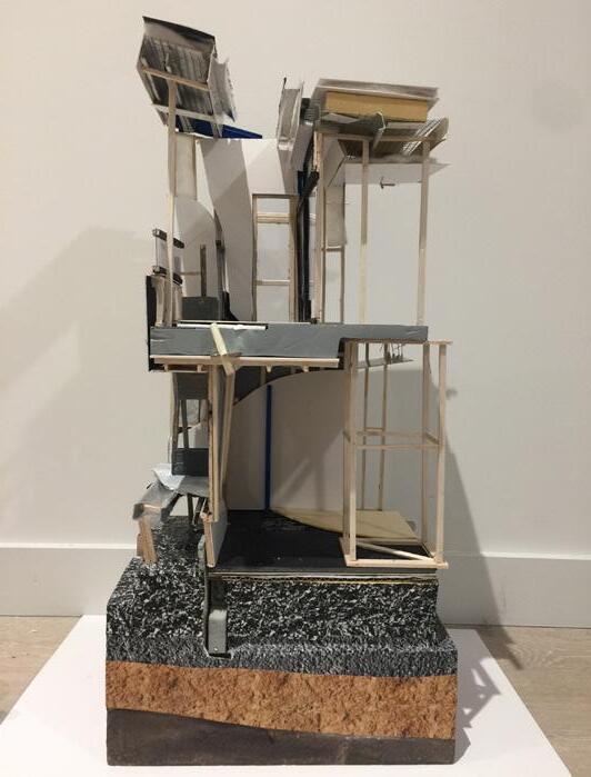

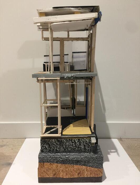
Academic, University of Melbourne, 2017, Semester-long
Tutor: Anthony Blazquez
Software: Rhino, AutoCAD
The sectional structural study on the Elizabeth Blackburn School of Sciences(EBSS). Expressed as a axonometric drawing and a 1:20 physical model, the purpose for each building element and chronology of construction was carefully examined, analyzing the relationship/conflicts between design intentions and feasibility of construction.