Introduction
Quick Explanation of a Heat Pump
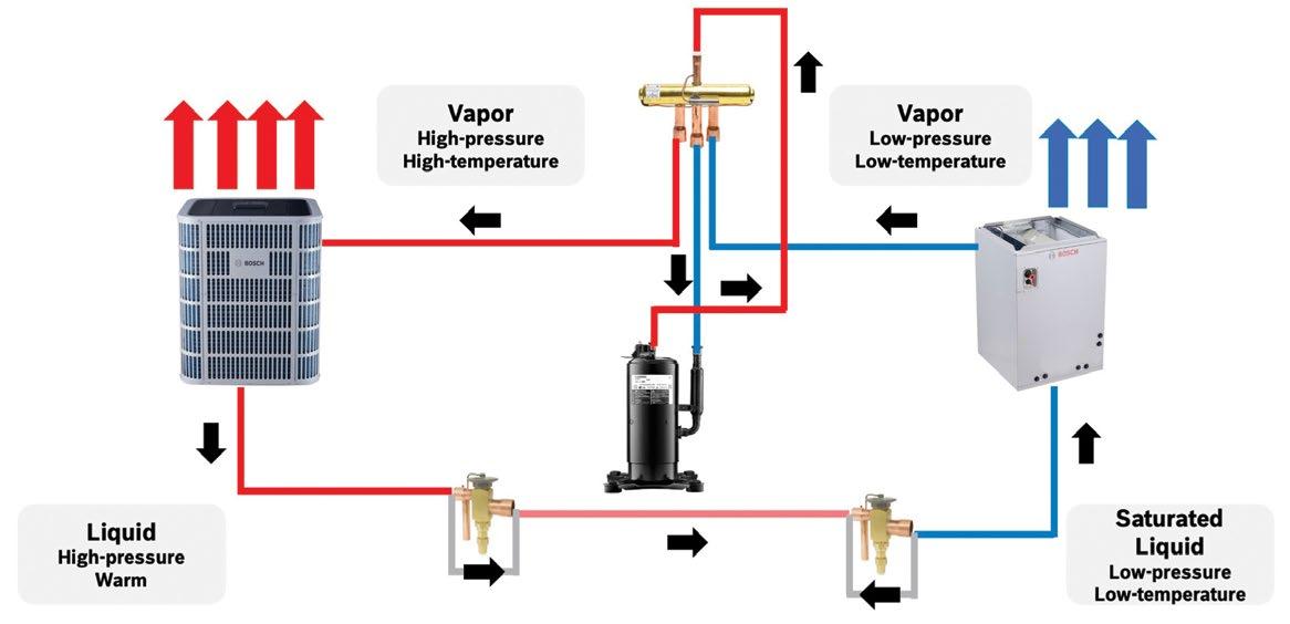
ASHPs have been common in the warmest parts of the United States for many years. In warmer climates these ASHPs are typically sized for cooling and offer a portion of the heating capacity needed on colder days, often assisted by back up heat if needed. These warmer climate ASHPs have typically been equipped with single speed, single stage compressors. For colder climates, these ASHPs were often sized to meet heating needs, while being oversized for cooling, resulting in moisture issues and inefficient operation. With the introduction of single-speed, two-stage modulating compressors, two stage ASHPs found increased use in colder climates, as they could operate at full load during winter and part load during summer. Most ASHPs are split systems with one coil and fan inside the structure (indoor unit - IDU) and another coil, compressor, and fan outside (outdoor unit - ODU), or systems with all coils, compressor, and fans outdoors in a single unit (package heat pump). Bosch ASHPs are available as ducted or ductless, depending on model, providing air distribution options for consumers.
Inverter-Driven
Inverter-driven CCHPs are equipped with inverters and variable speed compressors. An inverter is an electronic component that can turn Direct Current (DC) into Alternating Current (AC). The system converts 230V AC voltage to ~310V DC using a diode bridge rectifier. The DC voltage then passes through a filter, smoothing the voltage and sending it to an inverter. It is then “inverted”, or reformed, back into a 3-phase sine wave that is sent in small increments at different frequencies to control compressor speed. A variable speed compressor incorporates an inverter to allow it to be controlled digitally with DC voltage to ramp up or down in speed as needed to meet structure demand loads. CCHPs with inverter driven compressors operate almost continuously and are also self-analyzing and self-adjusting of structure load conditions while running. As they can operate at lower speeds versus fixed-speed and two-stage modulating compressors, they consume less power, which makes them the least expensive to operate over time.
The P-H Diagram
By far the Pressure-Enthalpy (P-H) Diagram is the best way to understand the challenges and enabling technologies of CCHPs. The P-H Diagram illustrates the vapor compression refrigerant cycle. The X, or horizontal axis, is H, or “Enthalpy”, which is “Heat Energy”. The Y, or vertical axis, is P, or “Pressure”, which represents the measurable pressure the refrigerant is under at a given point in the system.
There are two other notable features that help on the P-H Diagram. The first, which is always shown, is the “Vapor Dome”. This is the area where the refrigerant will exist as a saturated vapor and where the refrigerant is changing phase. It exists as some proportion of liquid and gas (or vapor). To the left of the dome the refrigerant exists as a liquid, and to the right it exists as a gas. Moving left-to-right the refrigerant is boiling (evaporating), while moving right-toleft the refrigerant is condensing.
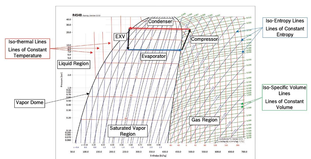
The second important feature, which is not commonly shown on all P-H Diagrams, are the “Temperature Iso-lines”. These lines indicate constant temperature, like elevation contours on a map. These lines are important as heat transfer is driven by a difference in temperature, thus, understanding what temperature exists where can indicate how heat will transfer. Inside the vapor dome temperature iso-lines are flat, as phase changes are a constant temperature process, making heat transfer very efficient. Outside the vapor dome, the temperature-iso-lines rise and fall very quickly, and heat transfer become very inefficient.
Coefficient of Performance (COP)
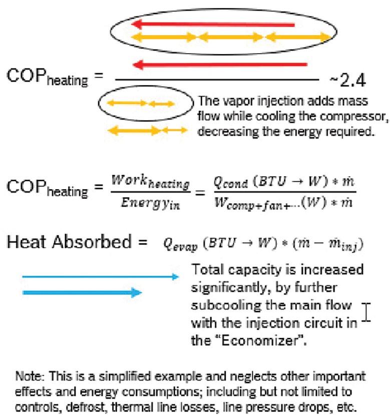
The “Coefficient of Performance”, or COP, is the engineer’s gold standard for understanding the performance of an air conditioner or heat pump. There are two different COP’s, and only one focuses on CCHPs. There is the Cooling COP, and the Heating COP. The CCHP focuses on the later. Simply put, the COP is the ratio of work or energy out of the system versus the energy put into the system. For heating, this would be the watts of heat energy (which can be converted to or from BTU’s) added to the conditioned space, versus the watts of electric energy required to move that energy.
Considering a couple of quick examples for different heating sources illustrates how to determine the COP value. Electric heating is typically the simplest, so, with a 5kW heat strip, the input is 5kW of electricity, and the output is 5kW of heat. This results in a formula of 5kW divided by 5kW, resulting in a COP of 1.0 in the best of cases, however it’s rarely best case. For natural gas or propane, imagine a 96% efficient gas furnace or boiler. The furnace or boiler is provided 100 kBTU worth of natural gas, or propane, and the output is 96 kBTU of heat for the conditioned space. This results in a formula of 96 kBTU divided by 100 kBTU, giving a heating COP of 0.96.
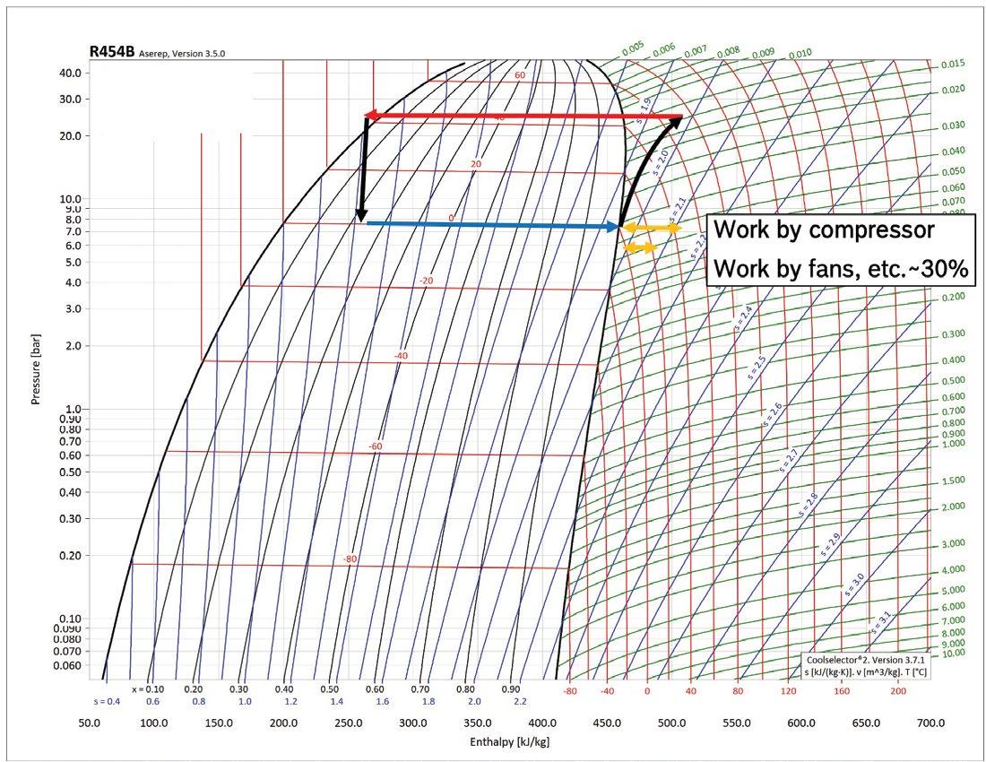
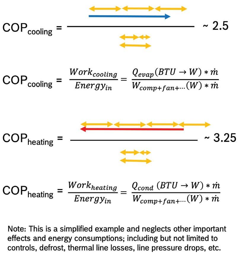
For a heat pump, this is where the P-H Diagram shines, as the X axis is energy. It allows determination of the COP right from the chart. Energy in is the electric energy into the compressor applied to compress the refrigerant. This is the horizontal distance of the sloped side of the trapezoid. Energy to heat the conditioned space is work done by the condenser, shown as the top line of the trapezoid. By comparing these distances, the COP of a heat pump will be around 3 to 4. The COP for cooling is the length of the sloped side versus the bottom flat line. The COP of cooling will always be lower than that of heating.
Problems in Cold Environments
Understanding the P-H Diagram illustrates the challenges of a CCHP, and examination of the temperature iso-lines indicates the problem. A reasonable head pressure, along with holding condenser temperature constant for comfort, is the goal. There are two limits to this assumption with trying to increase subcooling at the condenser. First, the condenser would need to grow much larger to hold more liquid refrigerant, which would increase the charge amount. Second, to further sub-cooling, which is no longer phase changing, the temperature is changing, and eventually the refrigerant matches the indoor temperature, stopping any further heat transfer. The P-H Diagram shows what will happen to the trapezoid as the temperature gets colder outside. The evaporator should typically be 10 to 20 degrees colder that the outside ambient temperature.
Trapezoid Narrows
The P-H Diagram shows as the trapezoid drops lower to maintain sufficient difference in temperature (ΔT) to the outside, the bottom of the trapezoid continues to shorten, meaning less heat can be absorbed from the environment. In addition, the sloped side for compressor continues to lengthen, meaning more electrical energy is needed for the system. This results in the COP decreasing, dropping closer, and closer, to 2, or even 1. As the sloped side increases vertically, the compression ratio of the compressor must increase to overcome a larger pressure difference.
Design Constraints
There are both pros and cons associated with increasing both subcooling and head pressure in the system that the P-H Diagram indicates.
For increasing subcooling, the top condensation line moves to the left to outside the vapor dome, increasing heat absorption and COP. However, at the same time, condenser area increases, comfort decreases, the process is limited by indoor temperature, and more refrigerant charge is required.
For increasing heat absorption, the compression line on the right moves further into the gas region, indicating more heat is available. However, suction pressure decreases, and the system is no better than straight electric resistance heat. Also, the discharge temperature is high, increasing the risk of compressor damage.
Other Challenges - Cold Startup
Cold climates affect the startup of CCHP components. Starting a heat pump is like starting a car. At rest, the refrigerant oil that lubricates the compressor, the bearing, and the internal seals, will pool in the lowest places of the system. This results in higher concentrations dissolved into the liquid phase of the refrigerant. Time is needed for enough oil to circulate through the system following a cold startup. Another issue is the accumulator will be full of liquid refrigerant when the system starts cold. This must be boiled off by exiting the evaporator before being pulled into the compressor, or risk of slugging the compressor occurs. Consequently, quick cold startups can always negatively impact the life of the CCHP components.
Another factor often overlooked is the effect of cold on magnetic forces. The compressor is a motor driven by electro-magnetic force. Struggling with a car in freezing weather indicates this situation. Cold decreases magnetic force, meaning that a motor (like a car’s starter motor) will require more current to start turning because it will resist movement. This also creates a risk of de-magnetization of the motor if it locks. Thus, strong batteries during winter with ratings by cold cranking amps are utilized for cars. Single-stage and two-stage traditional ASHPs all have high startup amps. Inverter technology solves both challenges, allowing the system to start slowly, while alleviating the cold induced current rush in a traditional single or dual speed system. The CCHP inverter system smoothly ramps up operation, avoiding spikes in energy use and protecting the system’s life cycle.
Hot Gas Bypass (HGBP)
Hot Gas Bypass (HGBP) is an option that regulates the temperature of an air conditioning system by diverting high-pressure, high-temperature refrigerant to the evaporator coil, artificially creating heat load.
Incorporating HGBP into CCHPs reduces excess cooling capacity when the return air temperature falls, but a cooling call is still active. When the refrigerant pressure is low, a “Hot Gas Bypass Valve”, added to the system opens, allowing refrigerant to bypass the heat exchanger, preventing the system from over-cooling.
The HGBP process provides heat even during slow starts that are designed to extend system longevity. As the compressor starts running, there will be hot gas coming out of the discharge from the first few cycles. At the same time there is a full accumulator facing the compressor inlet waiting to be boiled off. With HGBP a portion of the high-pressure, high-temperature gas, from the discharge is sent into either the evaporator, or the accumulator.
Using a “Proportioning Valve”, some of the discharge refrigerant can be re-directed into the evaporator for HGBP defrost, or directly into the accumulator boiling it off for it to be drawn into the compressor inlet. This warms the compressor oil, lowing viscosity and allowing it to be much more easily transported. HGBP can allow faster and safer startup from cold. By continuing to recycle a portion of the hot gas the compressor can reach its target discharge and pressure faster. This means faster heat to the conditioned space. As the system warms and reaches a steady state the proportion of hot gas bypassing decreases, returning to normal operation.
There are several different configurations for HGBP. The gas can be drawn from the compressor discharge, the condenser outlet, or a vapor injection circuit, and it can bypass to either the evaporator, or the accumulator. This was the key enabling technology that allowed Tesla© to be the first Electric Vehicle (EV) manufacturer to completely remove electric heat from their EV’s. At its worst, with all the refrigerant from the compressor discharge being bypassed to the inlet, the COP was driven to 1.0, the same as electric heat. This avoided electric strip heat while allowing fast warmups and windshield defrosting with the same efficiency as electric heat.
Flash Tank Vapor Injection (FTI)
In addition to starting CCHPs in very cold environments, high efficiency is also expected. “Vapor Injection” (VI) allows reclaiming of lost performance without sacrificing comfort. The first type of VI is called “Flash Tank Vapor Injection” (FTI), which provides a temperature lift to the vapor compressor cycle resulting in the heating performance improving.
FTI can be found on dozens of mini-split systems currently on the market and is a type of vapor refrigerant injection cycle that uses a “flash tank” to separate refrigerant into liquid and vapor phases. FTI also reduces the discharge temperature and improves heating performance of CCHPs during low outdoor temperatures.
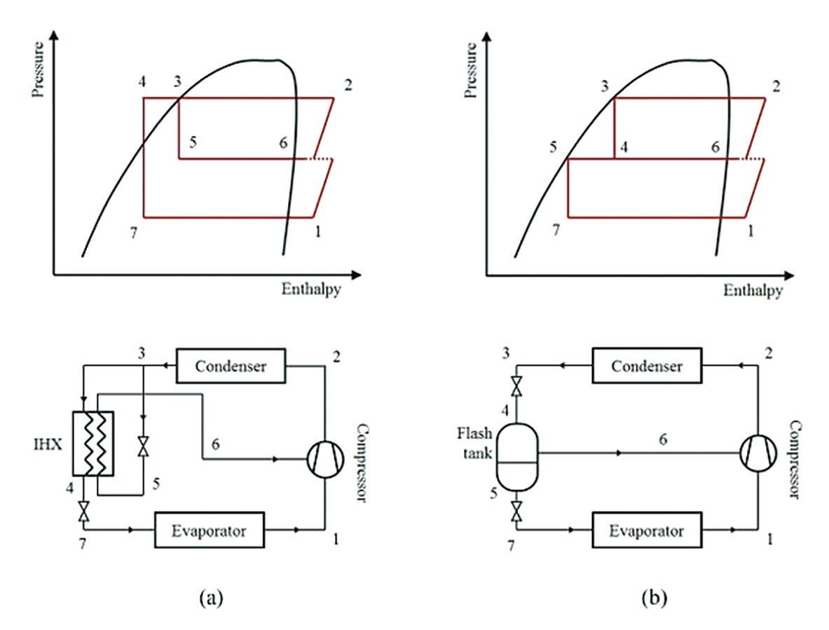
Returning to the P-H Diagram, assume that instead of expanding all the refrigerant from the discharge pressure down to the evaporator pressure, the refrigerant only goes halfway and stops in a tank. Now the refrigerant is at an intermediate pressure inside the vapor dome. There is some proportion of vapor and some liquid at this stopping point. If these two substances separated, we would have a large amount of liquid (~90%) on the left edge of the vapor dome and a smaller amount of vapor (<10%) on the right edge. Liquid on the left is now further to the left than the refrigerant that exited the condenser. If it continues to expand and move to the evaporator, it will absorb even more heat than before. This results in a small amount of vapor that “flashed” off when stopped, that needs to be returned to the flow. Taking this gas vapor and injecting it into the compressor during the compression cycle causes the compression ratio to effectively decrease. This means the compressor does not need to do as much work to generate the higher pressure required at very cold temperatures.
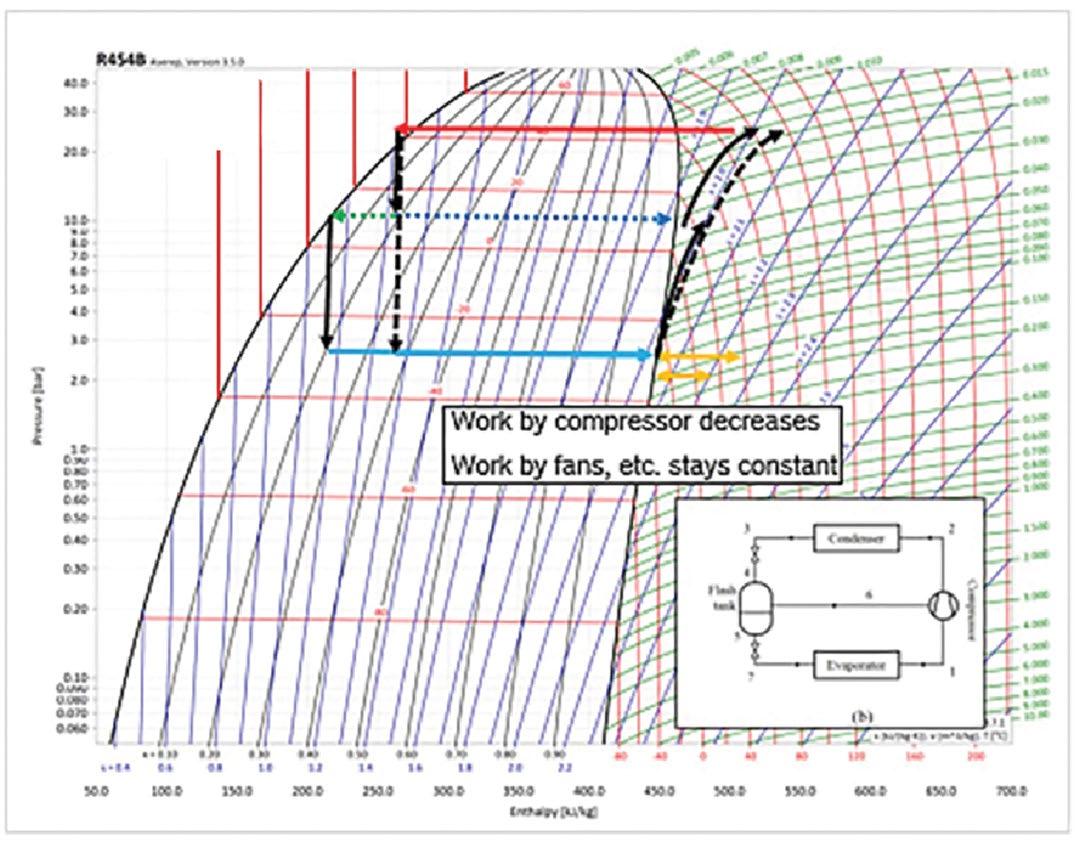
In its simplest configuration, FTI requires a second expansion valve, a storage or flash tank. and a compressor with a “Vapor Injection Port”. The FTI system is remarkably close to a purely mechanical system as it is designed without controls. The expansion valve could be a sensing thermostatic valve, ensuring the correct superheat through the vapor injection path. However, some control would be better and deciding whether FTI is needed for the specific conditions. In that case, an “Electronic Expansion Valve” (EXV), or a “Solenoid Valve” could be used.
2nd Expansion Valve
Storage or Flash Tank
Compressor with Vapor Injection Port
The FTI process involves refrigerant being discharged from the compressor and flowing through the condenser and an EXV, then entering the flash tank, where it is separated into liquid and vapor phases. The vapor is injected into the compressor, and the liquid enters a second EEV and circulates through the evaporator. Vapor from the flash tank increases subcooling which increases heat absorption in the evaporator from ambient air. Vapor injected into the compressor increases the quantity discharged to the condenser improving the heat exchange capacity. The process saves compression work of the compressor, while increasing performance.
Enhanced Vapor Injection (EVI)
The second type of VI is called “Enhanced Vapor Injection” (EVI), which also provides a temperature lift to the vapor compressor cycle resulting in the heating performance improving. As compared to the FTI process, the goal is to continue sub-cooling the refrigerant after the condenser. FTI is effective in splitting the refrigerant into vapor and liquid. With EVI, this splitting occurs as well after the condenser in the range of 90%-10%.
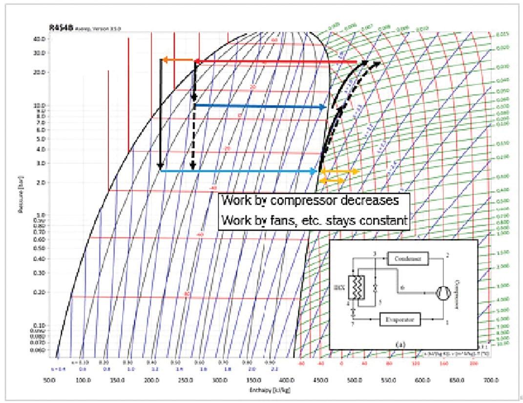
With EVI, a small flow of refrigerant passes through an EXV, decreasing the temperature in the process to an intermediate pressure. This bypassed flow is sent through a “Plate Heat Exchanger”, or “Economizer”, crossing with the main flow. This heat exchanger acts as a sub cooler for the main mass flow and as an evaporator for the injection mass flow. The result is the main flow is further sub-cooled by this bypassed and expanded flow (further to the left on the left on the P-H diagram). When the main flow is expanded through the EXV it can absorb more heat from the surrounding environment. As with FTI, the bypassed flow can be injected back into the compressor during the compression cycle.
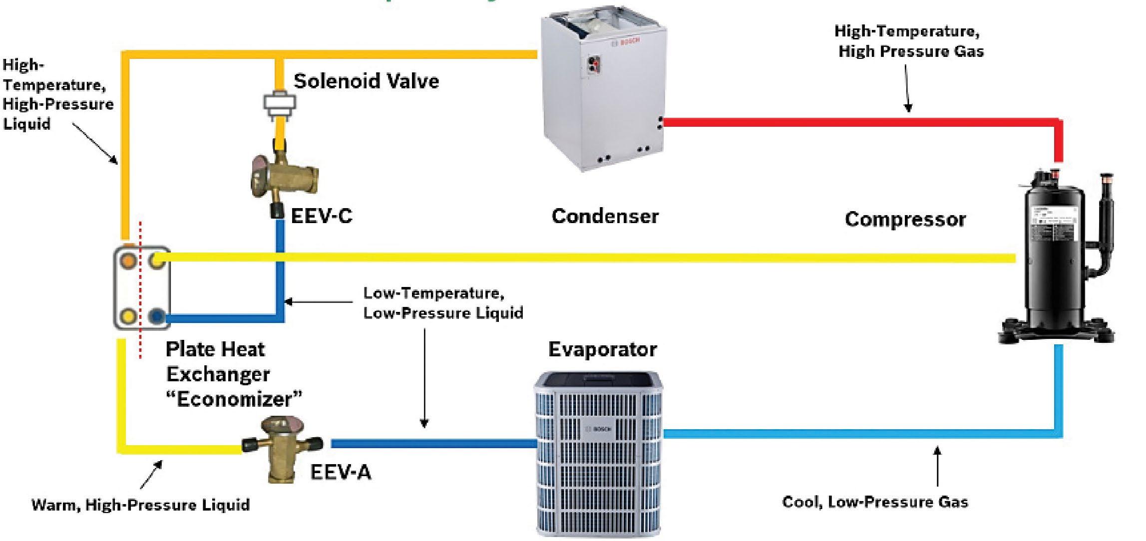
EVI requires a different set of components and a more active control strategy to operate efficiently than FTI. These EVI components include a second EXV, a temperature sensor to monitor super heat for the VI circuit, a plate heat exchanger, and a “Vapor Injection Compressor”. Additional controls allow EVI to outperform FTI in terms of efficiency, allowing for the main flow to be subcooled beyond the edge of vapor, while allowing more heat absorption. EVI is making its way to market in several cold climate rated unitary split systems.
Conclusions
The latest generation of CCHPs present an opportunity for improved heating efficiency. They are not simply re-branded versions of their southern climate predecessors, but an evolution, which is the result of decades of engineering, testing and validation. New inverter driven ASHPs with fast startups enabled by the Hot Gas Bypass option provide extended cold climate performance due to VI. FTI is found in mini-split systems, providing a simple and cost-effective solution to extended performance in cold climates. These systems are ideal for retrofit applications where a gas or oil boiler may have been the primary source of heat and can be displaced or utilized as back-up in dual fuel setups. EVI in unitary systems offers more efficiency and control and are ideal for new construction with familiar and similar installation, or as a replacement or complement to an existing gas furnace. By incorporating these advantages, VI technology enables CCHPs to serve as effective primary heating systems in cold climates, reducing or eliminating the need for backup heating sources. As a bonus, they can also provide superior dehumidification in summer.
About Bosch
Bosch Home Comfort Group in North America
Bosch Home Comfort Group is a leading source of high quality water heating and comfort systems. The company offers gas tankless, electric whole house and point-of-use water heaters, Bosch and Buderus floor-standing and wall mounted boilers, Bosch and FHP geothermal, water-source and air-source systems as well as controls and accessories for all product lines. Bosch Home Comfort is committed to being Simply Smart by offering products that work together as integrated systems that enhance quality of life in an ultra-efficient and environmentally friendly manner. For more information, visit bosch-homecomfort.us.
Bosch Group
The Bosch Group is a leading global supplier of technology and services in the areas of Automotive, Industrial Technology, Consumer Goods and Building Technology. The company was founded in Stuttgart, Germany, in 1886 and presently has more than 440 subsidiaries and is represented in over 150 countries.
In the U.S., Canada and Mexico, the Bosch Group manufactures and markets automotive original equipment and aftermarket solutions, industrial drives and control technology, power tools, security and communication systems, packaging technology, home comfort solutions, household appliances and software solutions. The Bosch Group’s products and services are designed to improving quality of life by providing innovative and beneficial solutions. In this way, the company offers technology worldwide that is Invented for life. Additional information is available online at www.bosch.com
Bosch Home Comfort Group
Watertown, MA | Londonderry, NH | Ft. Lauderdale, FL
General Inquiries: 1-866-642-3198
Copyright © 2025 Bosch Home Comfort Group All rights reserved. Subject to change without notice.
77H992877G 1-25
www.bosch-homecomfort.us


