14 minute read
CAUTION
from NIKKEN
・Please use a collet for the chucks. ・Please use a chuck for the collets.
may not be performed 100% using on the other makers chucks.
・Please be careful not to inflict personal injury at your handling of cutting tools. ・Please clean the contact surface on a holder & cutting tool shank. ・Please pay attention to prevent from the rust at the storage. We will recommend to use NIKKEN
TOOLINGS with RPT process for rust prevention.
Due to the optical system to detect the tool existing on the tool magazine of certain machines,
NIKKEN's RP treated tooling may not be detected.
Please check your machine's specifications very carefully to avoid this problem before you purchase our RP treated tooling.The taper connection of the tool shank with RP treatment is
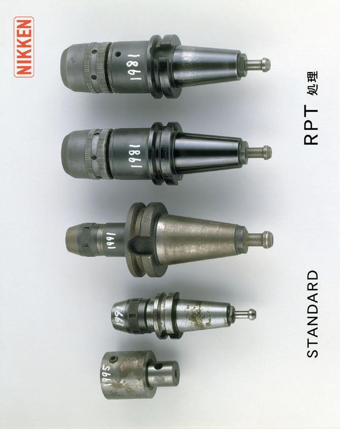
Standard 8 years used
RPT 18 years used
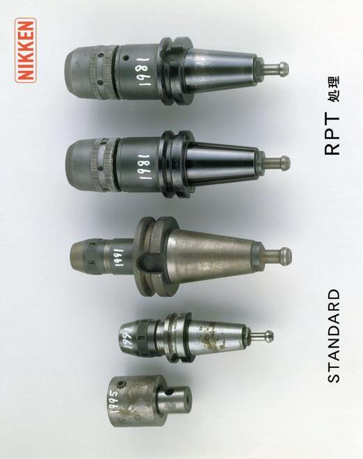
more stuck than the taper connection of the tool shank without RP treatment. Then, the unclamping force for the tool with RP treatment is required 20% stronger than the unclamping force for the tool without RP treatment. Please be careful to check the unclamping force of your M/C, when the tool with RP treatment is chosen.
・Please do not use the tooling that has scratches, damaged or rusted on its taper. This may cause false accuracy readings and reduce cutting performance. ・Please pay attention not to inflict personal injury with the broken tools or swarfs. ・Please do not modify the holders by yourselves. ・Please do not touch the tool at its rotating. ・Please do not touch the tool just after machining, it might be very hot. ・Please check if the cutting tool is held with the holder properly before the machining. ・For high speed application, please use NIKKEN HIGH
SPEED TOOLINGS or the pre-balanced toolings.
Caution for Tooling
MTA
・Please insert the tool shank into the bore of the holder with adjusting the tang location, and hold them with facing tool front end upwards, and hit the bottom end of the holder(pull stud end) by copper hammer hardly. ・For removal of the tool, insert a bar into tang hole and hit the bar by hammer with special care to prevent the tool from popping out. ・Please clamp side lock screw in case of coolant through application. For high pressure coolant
through application, please use milling chuck, slim chuck or side lock holder instead of MT adapter. MTB
・Please insert the tool shank into the bore of the holder and tighten the draw bolt for the setting. ・For removal of the tool, loosen the bolt at couple rotation and hit the bolt head by a hammer in order to remove the taper fitness,then remove the bolt.
SCA, SCC
・When setting of side cutter or metal saw onto the arbor, please adjust the location of the drive key.
JTA
・When setting drill chuck onto the arbor please put the chuck onto the arbor with adjusting the locations of male & female tapers and hit the bottom end of the holder(pull stud end) by copper hammer. ・Please use NIKKEN SLIM CHUCK for high precision and high speed operation.
NPU
・Please insert the drill shank into the bottom, and chuck the shank with the total chucking length of NPU. ・Please check the run-out accuracy before machining especially for the small diameter drill. ・When setting the drill onto the chuck, set the drill into the chuck and tighten the chuck ring by hand then tighten the ring by attached spanner to complete.
NG
SL, SLA, SLB, SLS, DM
・When setting the tool onto the holder, adjust the locations between notches or flat face of the tool shank and side lock screws, and tighten the screws completly. ・The dimension of the flat portion of the cutter shank varies, therefore please select a proper holder according to the cutter shank dimension. ・Code No. of the side lock holder for oil hole drill is
SL○C. OK25~OK40 collet can be used for SL○C.
Type
SL
SLA
SLS*
WE
Cutter
6~ 16 Drill,Endmill 20~ 42 Endmill 6~ 50 Endmill Inch Size Endmill Axitial Adjustment
SLB
Drill Used with DSA socket *SLS is the holder for JIS B 4005 endmill or weldon type endmill.
FMA, FMB, FMC, SMA, SMB, SMS
・Please use the bolt specified by the cutter maker. ・When setting the face milling cutter onto the arbor, insert the spigot of the arbor into the cutter bore and minimize the backlash between the drive key and the slot against the direction of rotation, then tighten the end bolt. ・For the cutter with coolant through the body, please check the coolant pass in the arbor and the cutter before machining. ・For high speed application, please perform the balancing operation with the cutter and insert tips fitted.
PS
・The pull stud is considered to consumption item and should be replaced pediodically. The guide line of replace ment is ;
Without hole : 3 years or 150,000 times of ATC.
With coolant hole : 2 years or 100,000 times of
ATC.
φd2
Caution for ・
・Always ensure that M/C has the mechanism to confirm the perfect flange contact. ・Always ensure that M/C has the mechanism to clean the spindle flange surface. ・Please ensure that the suitable spacer is fitted on the machine spindle flange when the tooling is used on the standard BT/IT/CAT spindle machine. Please do not use the tooling on the standard spindle machine without the suitable thickness of the spacer.
Caution at Use
・Always ensure that swarf should not attach at the spindle flange surface of the double contact system. Generally the inside of the machining envelope is always covered with swarf. This means that there is a possibility that the flange of the tooling may collect swarf easily at the ATC. It is therefore important that the machine envelope is regularly cleaned(Clean the ATC arm, the route through which the tooling passes, the tool pot and the spindle surfaces etc.)at least every 3 months. ・The rust or fine swarf may be fitted on vacant pot inside. So, if ATC mechanism of your M/C is random pot change mechanism(the tool on the spindle is returned to the pot in which the next tool is stored), please insert the dummy tool into all vacant pots to protect this. ・Caution for centre through tool coolant application There are 2 types of the sealing method of the coolant at pull stud, sealing of face contact and sealing of taper contact. please choose the proper pull stud for your M/C. ・If your center through tool coolant M/C does not have the sealing mechanism at pull stud, the coolant stays inside the spindle and is sealed at BT/IT taper connection. tool can not seal the coolant at taper connection, because the taper cone of tool has the slit.Please select tooling instead.
Pulling Force of the M/C
・If the pulling force of machine spindle decreases substantially, the NIKKEN tooling cannot perform 100% at O-ring O-ring its capability. We would recommend that regular inspection of the pulling force is carried out to prevent any reduction in the pulling force at an early stage. Please refer P.269 for pulling force measurement tool. ・When the pulling force of the M/C became too low, tool can not perform its capability. Please ensure the MIN. pulling force as follows:
MBT40: 5KN Sealing of Face Contact Sealing at Taper Contact
MBT50: 15KN The periodical inspection of the pulling force is required. Coolant
Rust Proof Treatment
・The taper connection of the tool shank with RP treatment is more stuck than the taper connection of the tool shank without RP treatment. Then, the unclamping force for the tool with RP treatment is required 20% stronger than the unclamping force for the tool without RP treatment. Please be careful to check the unclamping force of your M/C, Slit when the tool with RP treatment is chosen. ・Therefore, the taper cone of tool and NC5 tool is changed to without RPT treatment as standard. And the special anti-rust treatment is applied to the taper cone of the tool and NC5 tool. M/C with Flange Trough Tool Coolant ・When the stroke of the coolant nozzle at spindle flange is not sufficient on BT/IT standard M/C, tooling may Coolant can not be sealed at taper connection for tooling. not be used due to the collision. Please check the specification of your M/C. Please tooling instead.
① Wipe all dust and oil from internal bore of chuck, inside and outside of collet, and
shank of cutter.Clean minute dust inside slot grooves of collet by air blow. When
cleaning please use gloves and safety glasses. You are recomended to use ⑤ CCK
collet & CKFN nut to prevent the dust or swarf from getting inside.
② After setting End Mill into collet insert them into the chuck.
③ To tighten the nose ring lightly until to contact with the the
flange surface of the chuck body is ready to use. If the nose ring is contacted too strongly, it may cause the internal stress higher, and the run-out accuracy may not be accurate.
-Please use End Mill of h7 tolerance shank. -Please use End Mill with h6 shank tolerance for high speed machining. -Clamp as much of the shank of End Mill as possible. -Insert Collet into Chuck until the flange of collet touches the surface of the front end.
Solution
Return the nose ring just a little to tap slightly as illustration at right hand side. This operation releases the internal stress, and the run-out accuracy will be recovered. To release the internal stress is recommended for all milling chucks.
④ For IT(ISO) / CAT taper, please be careful to check the dimension "D" with your machine.
φD
The dimension of“D”of some models are greater than
the specification of your machine.
⑤ When using CCK32-16,20,25 Collets with CKFN32T Front Nut, please set the rear slits of the Collet to the same location of the slots of the Milling Chuck.
How to use CCK Collet.

② ③ ④ Completed
Face Cantact
Nose Ring
CCK Collet
①
CCK Collet
CKFN Nut Gap (0.5~1mm)
①Loosen the front nut on the collet to provide a small gap between both contact surfaces of the collet and the nut. ②Insert the collet with the cutter into the chuck until the collet flange touches the chuck front flange sur-face. Adjust the required length of the cutter. ③Tighten the nose ring until the nose ring cont-acts the chuck ground surface. ④Tighten the front nut thoro-ughly with CCKL
Spanner (Option)until the nut flange surface contacts the chuck front flange surface. (Perfect
Sealing) ⑤When removing the cutter : Loosen the nose ring first, then remove the collet and the cutter.
For the next set up, please start from the operation ① .
Direct chucking
Tighten by hand. DO NOT USE HAMMER!!
No Axitial Movement.
Standard Front Nut with jet coolant groove CKFN
The jet coolant pressure creates a tornado effect, ensuring efficient swarf dispersal. And prevention of swart and dust contamination.
Front Nut with O-ring CKFN-C
This front nut has O-ring fitted at the internal diameter for the cutter with coolant hole.
Front Nut with multi nozzle CKFN-MN
This front nut has multi nozzle for the cutter that has larger front end diameter than its shank diameter.
With jet coolant groove e.g.CKFN32-32D
With O-ring e.g.CKFN32-32DC
INSTRUCTION & CAUTION (TiN BEARING NUT SERIES)
Always ensure that there is no damage on the internal bore of the chuck, the internal & external of the collet, and the Cutting tool shank.
Wipe all dust from internal bore of chuck, inside and outside of collet, inside of nut and shank of cutter.
Clean minute dust inside slot grooves of collet and inside of nut by air blow.
We will recommend to use J type nut to prevend swarf and dust contermination.
Set SK Collet into SK Nut. Collet Extractor(SKR-6)is used only for SK6.
Screw SK Nut into Slim Chuck spindle. -Do not insert a SK Collet alone into Slim Chuck spindle.
Insert cutting tool shank into SK Collet. -Protection must be used to grip cutter teeth. -Use a proper SK Collet to grip a cutter shank. -Use “A” type SK Collet to grip a cutter with End Mill shank. Gripping range of “A” type SK Collet is h8. -Clamp as much of the shank of cutter as possible.
After tightening SK Nut by hand, tighten further by spanner.
This is the precision tool, tighten the nut with the suitable tightening torque !
-Clamp the cutter shank as long as possible. -Tighten the nut with the suitable tightening torque listed below. If the torque is
exceeded,it may cause the breakage of a collet or a chuck itself.
-Tighten the nut slowly by the torque wrench. When the torque limiter is worked (a sound click), stop tightening immediately.Do not tighten with the torque over the torque limiter.
1
2
3 1
2
3
Slim Chuck VC Holder
Style
SK 6 SK10 SK13 SK16 SK20 SK25
~ 3mm 10~20 20~25 Cutter Dia. 4~ 6mm 20~30 30~40 40~50 8~φ10mm 12mm~
Click
Torque Wrench Always ensure that the slim chuck is set up on the proper fixture, e.g. tool clamper TCL-GH, P.236 when the nut is tightened.
INSTRUCTION & CAUTION (PULL STUD)
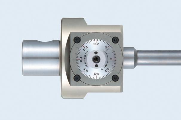
ZMAC BORING HEAD
How to preset boring diameter 1) Loosen Side Lock Bolt before turning of dial ring. Preset boring diameter by turning dial ring with attached spanner. 2) Adjustment always has to be done in clockwise (+ direction) , and if you go beyond the required graduation, rewind the dial ring half a turn and readjust. 3) Tighten Side Lock Bolt after adjusting. How to exchange Cartridges 1) Loosen Side Lock Bolt. 2) Turn dial ring in an anti-clockwise (-direction) to remove the Cartridge from the boring head. 3)To set new Cartridge in, insert into location hole and turn and dial ring in a clockwise (+ direction), the Cartridge will settle in gradually. How to exchange Cartridge Heads for ZMAC42 or larger heads 1) Adjust the diameter to just a little bit bigger tan Min. Diameter of the Head. 2) Then, loosen the Head Clamp Bolt to remove the Cartridge Head. 3) Insert new Cartridge Head into the shaft, then tighten the Head Clamp Bolt temporary. 4) Loosen the Side Lock Bolt. 5) Turn the Dial Ring 0.2~0.3 mm to the minus direction. 6) Tighten the bolt by pushing the Cartridge Head strongly into the shoulder of Boring Head.
This is very important to keep Shoulder Contact ! 7) Then, tighten the bolt completely.
Side Lock Bolt
Head Clamp Bolt
RAC BALANCE CUT BORING HEAD
How to preset boring diameter It is possible to preset boring diameter in Machine but basically please preset boring diameter with presetter.(○ A) 1)Temporary tightening Loosen cartridge clamping bolts on both sides first and tighten them slightly. (○ B ○ C) 2)Diameter adjusting (Front side) Put dial gauge at the edge of insert and preset the diameter with L wrench. After fixing the cartridge, do not adjust the diameter. Center pin could be broken. 3)Diameter adjusting (Back side) Same way as 2) 4)Dimensions confirmation Confirm if the difference of right and left diameter is within 0.1. If over 0.1, preset one cartridge only again from 1)step.
○ A ○ B ○ C
DJ BORING HEAD
Setting of DJ Boring Bit
Select a boring bar that is suitable for the required diameter and depth from the DJ Boring Bit list. Set the Boring Bit into the head so that the insert faces the location line on the head (opposite side to the dial ring). Following this operation, tighten the set screws for Boring Bit on the opposite side of the dial ring.
Operation of the Dial Ring 1) Always ensure that the locking screw for adjustment has been loosened. 2) Always rotate the dial ring in the same direction (+direction) .
If the desired diameter has been passed, wind off the dial by approximately 0.2mm and re-adjust. 3) Always tighten the locking screw after the adjustment has been completed.
・The guide line for pull stud tightening torques are as follows;
BT30: 20 ~ 25 N・m
BT40: 60 ~ 80 N・m
BT50:200~250 N・m ・For high precision BT30 tooling (e.g. Milling Chuck, Slim Chuck and Mini-Mini Chuck etc), the tooling completely with pull studs fitted is also available. Please contact with us to arrange this option. ・MAS BT30 centre through pull stud ( d2=7mm)cannot be recommended by its weakness due to thin profile.
When purchasing a #30 taper machining centre with centre through coolant capability, we can highly recommend a machine using the NIKKEN NC5-46 spindle.
・JIS40 type pull stud ( d2=14mm)is highly recommended for centre through coolant machining centre instead of MAS BT40 type ( d2=10mm). ・When pull stud without hole is used on the centre through tool coolant M/C, please use the pull stud which top surface is ground. ・The special pull stud with O ring is required for the M/C with flange through coolant capability. ・We recommend you regularly check the measurement of the pulling force to discover any problems at an early stage. Please use NIKKEN Pulling Force Measuring Tool (CLP) to perform this check. ・Please use pull stud, do not use any pull stud which has damage marks on its draw head area or is deformed. ・The pull stud is considered to consumption item and should be replaced pediodically.The guide line of replace ment is ;
Without hole : 3 years or 150,000 times of ATC. With coolant hole : 2 years or 100,000 times of ATC.
φd2
TAPER BT30 BT40 BT50
CLP
Code No. BT30-CLP BT40-CLP BT50-CLP


