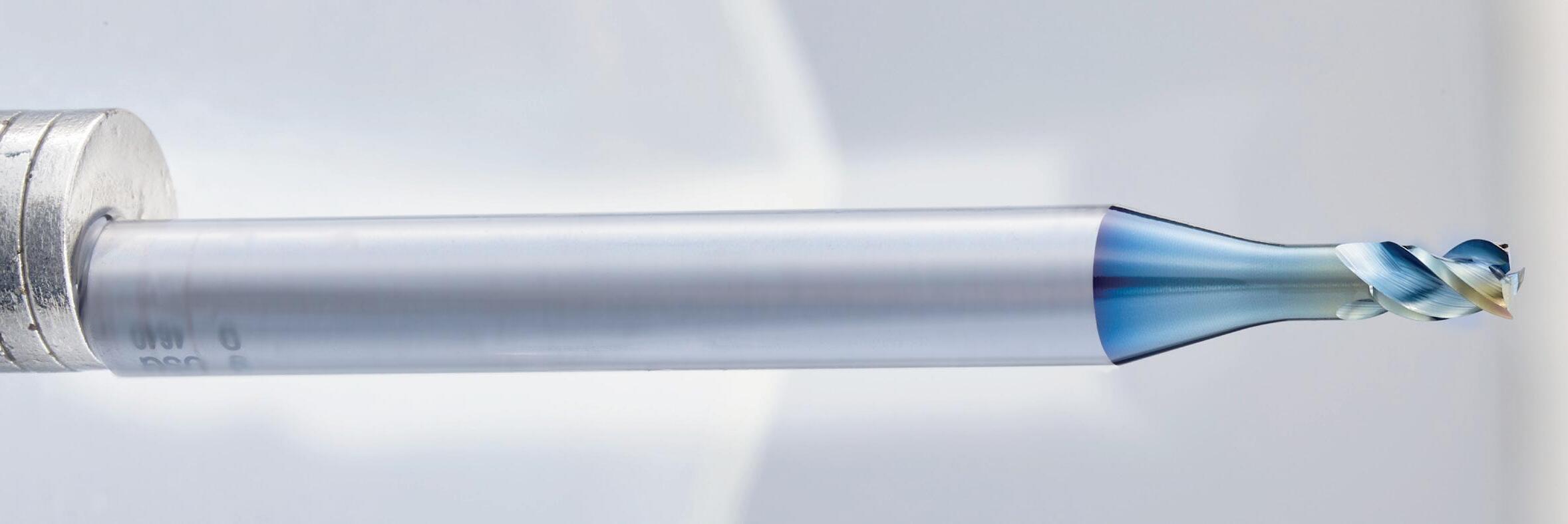
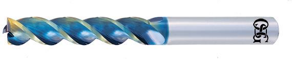
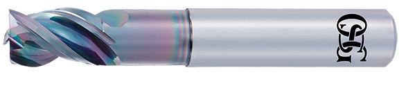
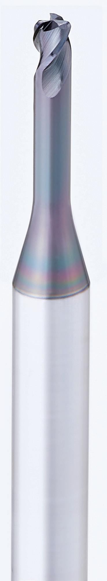
DLC Carbide End Mills for Non-ferrous Materials


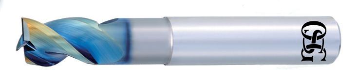
AE-TS-N
AE-VTS-N Short (High performance type) AE-LNBD-N AE-CPR-N
AE-VTFE-N (Deep side milling)


AE-TS-N
AE-VTS-N Short (High performance type) AE-LNBD-N AE-CPR-N
AE-VTFE-N (Deep side milling)
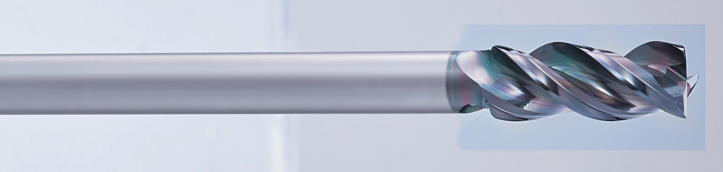
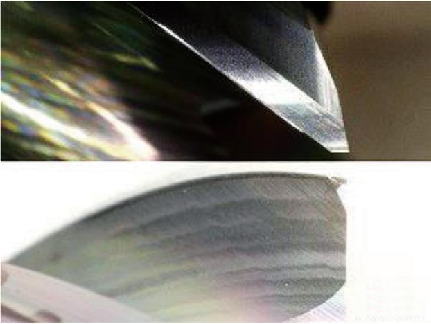
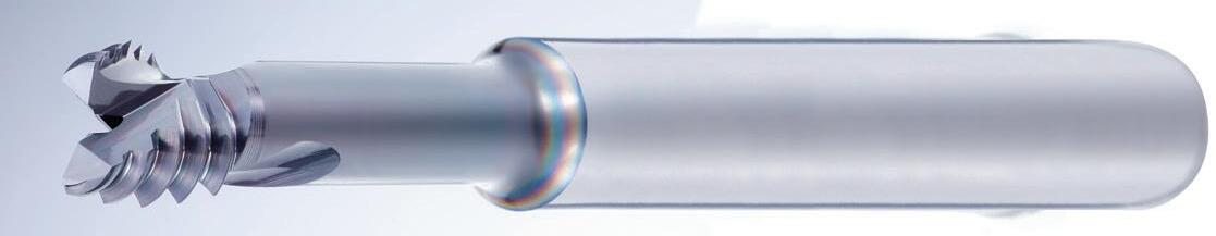
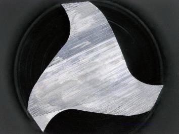
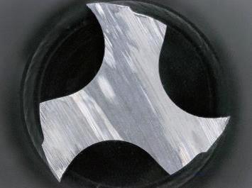
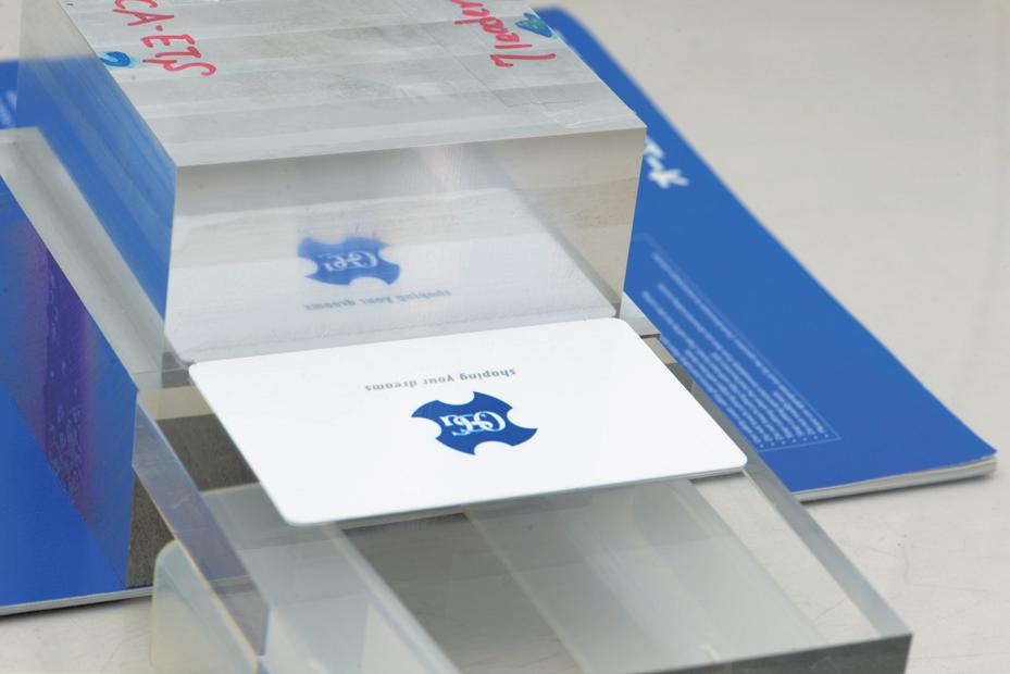
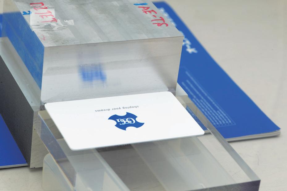
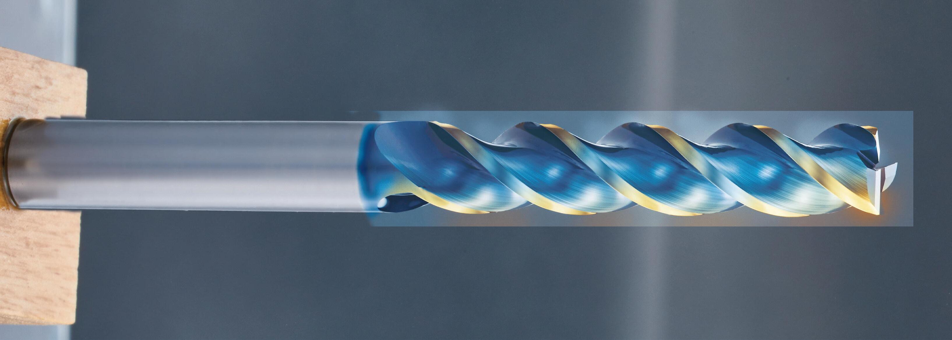
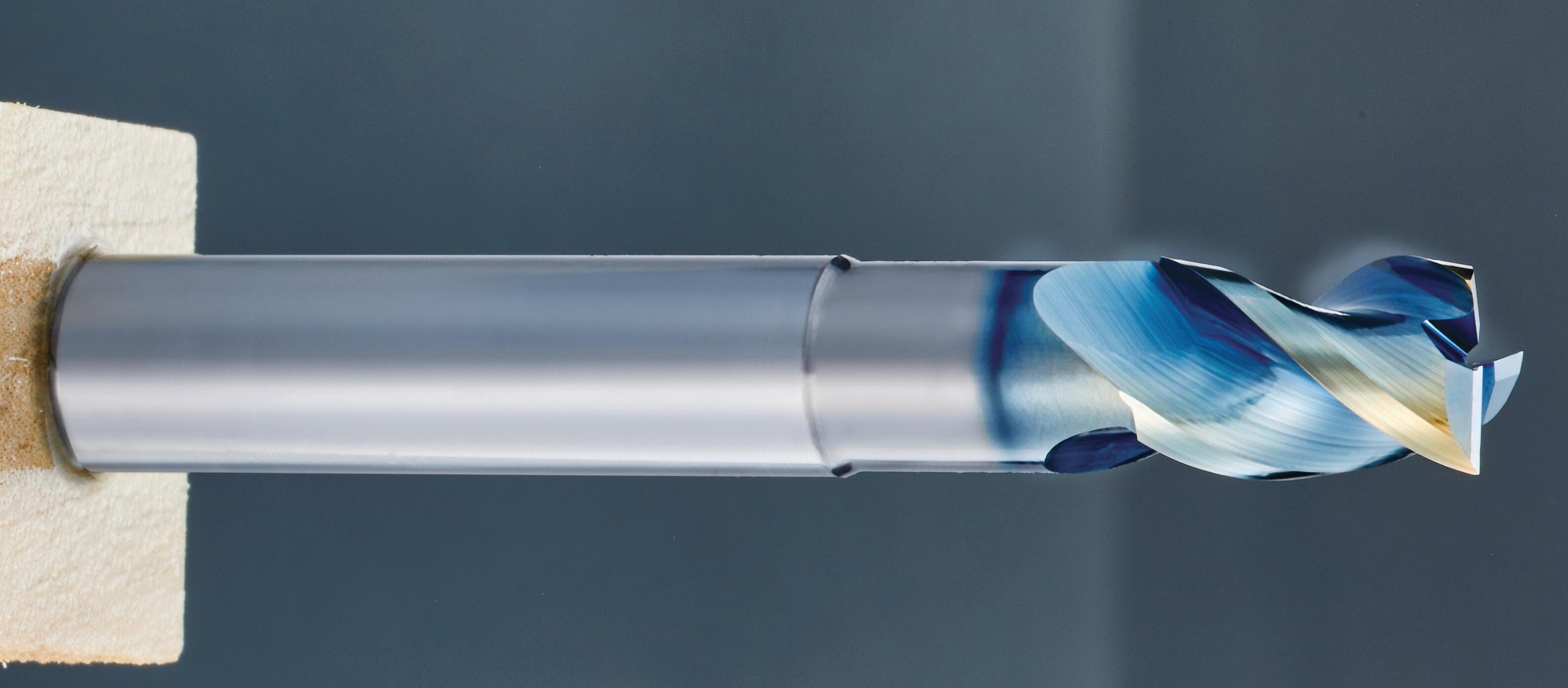
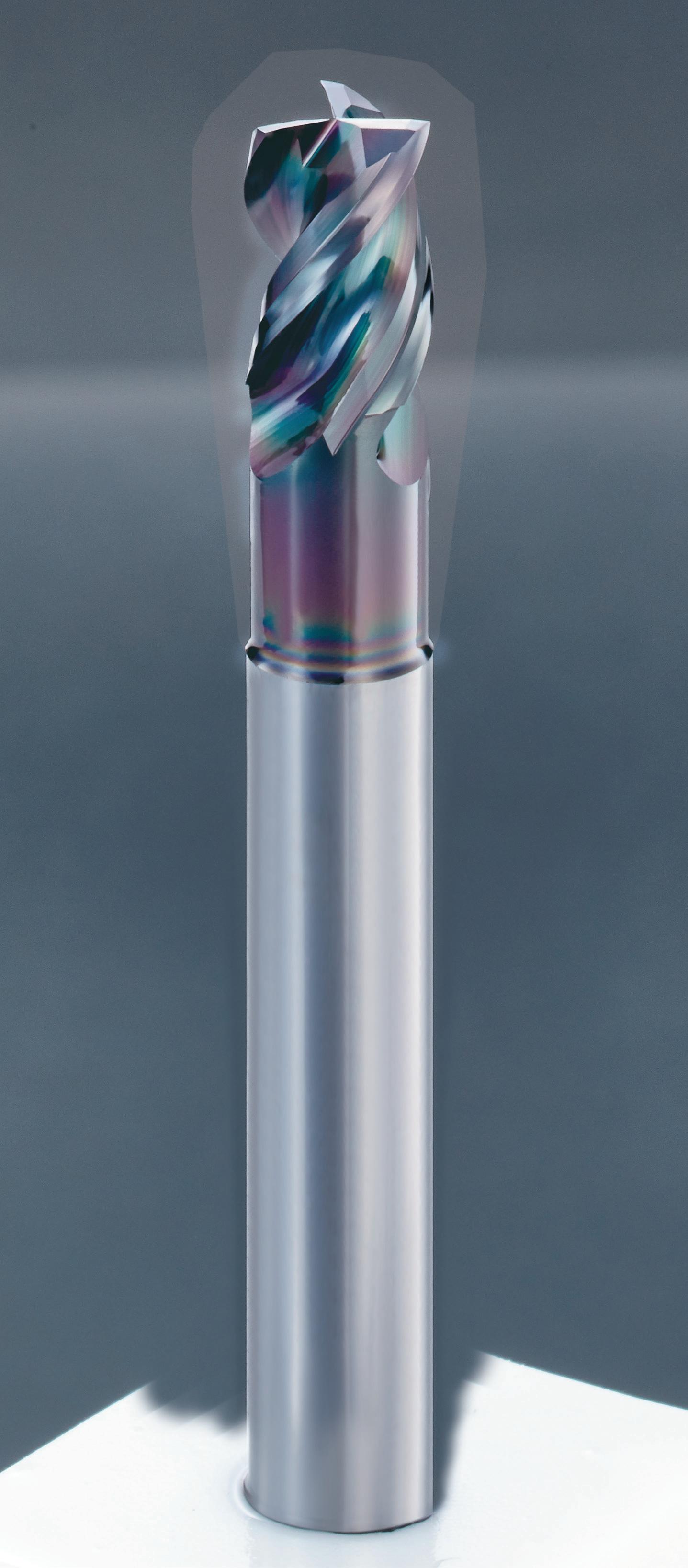
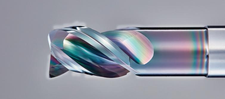
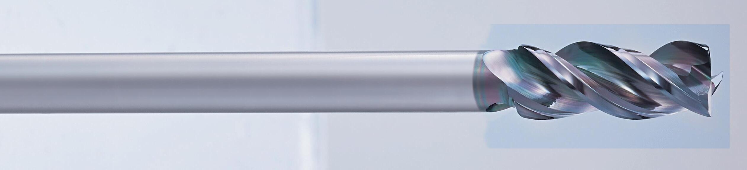
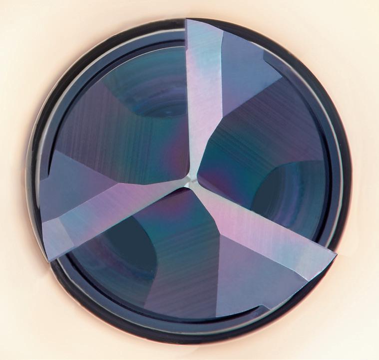
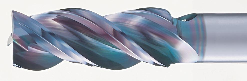
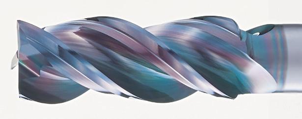
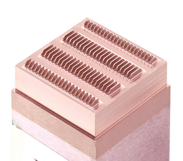
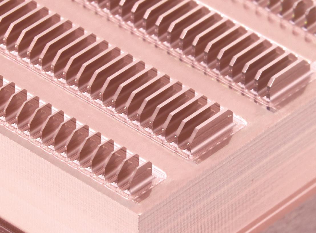
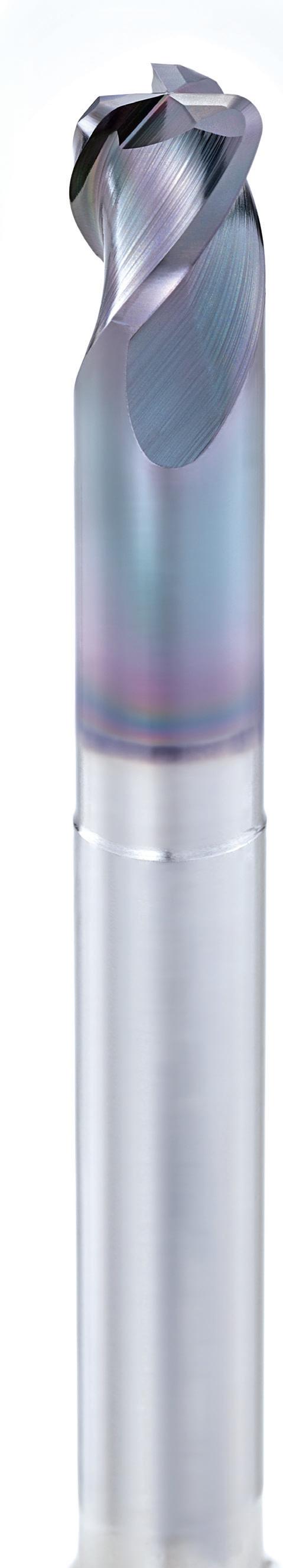
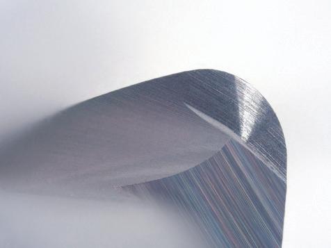
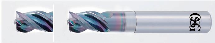
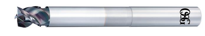
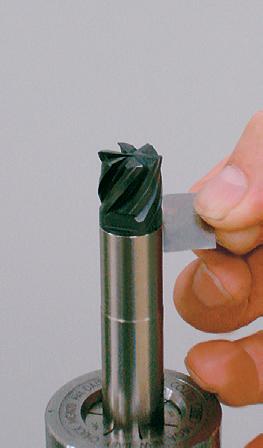
OSG’s DLC coating gives a shiny surface! This shiny and smooth surface optimizes end mill performance particularly in non-ferrous materials such as aluminum alloys, which require welding resistance and lubricity.
Thick coating type for long tool life
Thick coating type suppresses wear on the cutting edge to enable high durability and long tool life.
Applicable tools : AE-VTS-N • AE-VTFE-N • PXAL
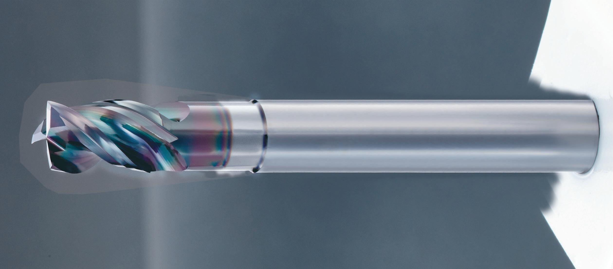
Thin coating type with emphasis on sharpness
High adhesion to the base material to enable sharp cutting performance and high welding resistance.
Applicable tools : AE-TS-N • AE-TL-N • AE-VTFE-N
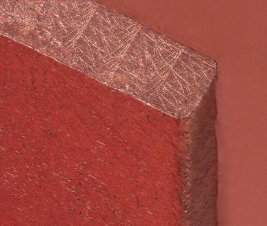
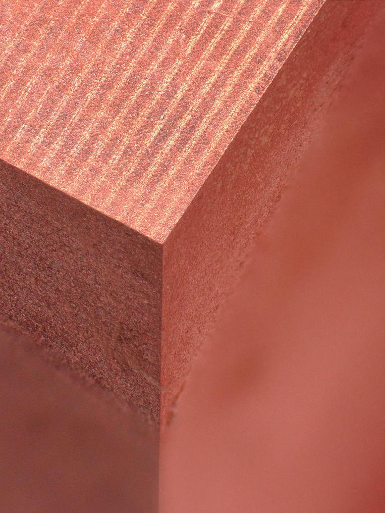
OSG’s DLC coating has high wear resistance and anti-adhesion properties, which enable stable tool life in non-ferrous material applications with high tendency to weld.
Milling in A5052
Tool Carbide Square End Mill 3 Flutes
Work Material A5052
Cutting Speed 200m/min (6.370 min-1)
Feed 0,08mm/t (1.530mm/min)
Depth of Cut ap = 5mm ae = 8mm
Coolant AirBlow
Machine Vertical Machining Center
Milling Length 50m
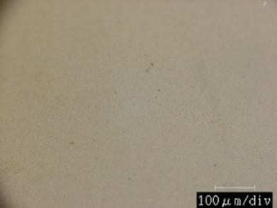
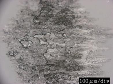
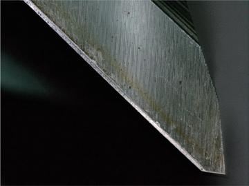
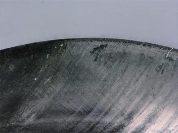
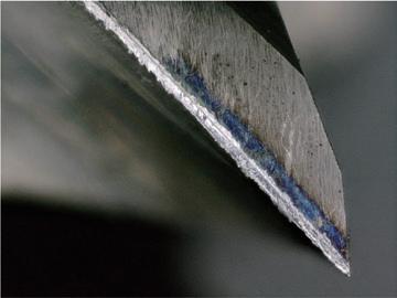
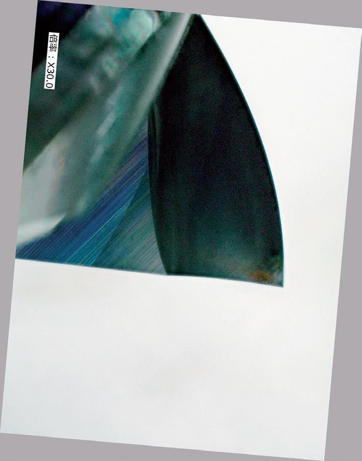
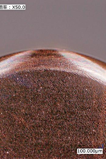
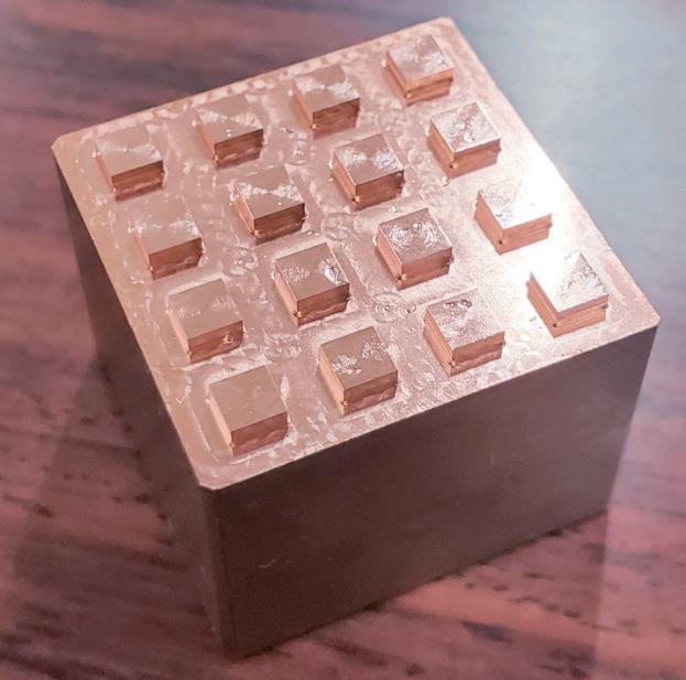
Surface condition after pin-on-disc test
Coolant MQL
Max. RPM 25.000 min-1
Holder Shrink Fit
Work Material A5052
Machine 5 axis Machining center
Main Spindle HSK63
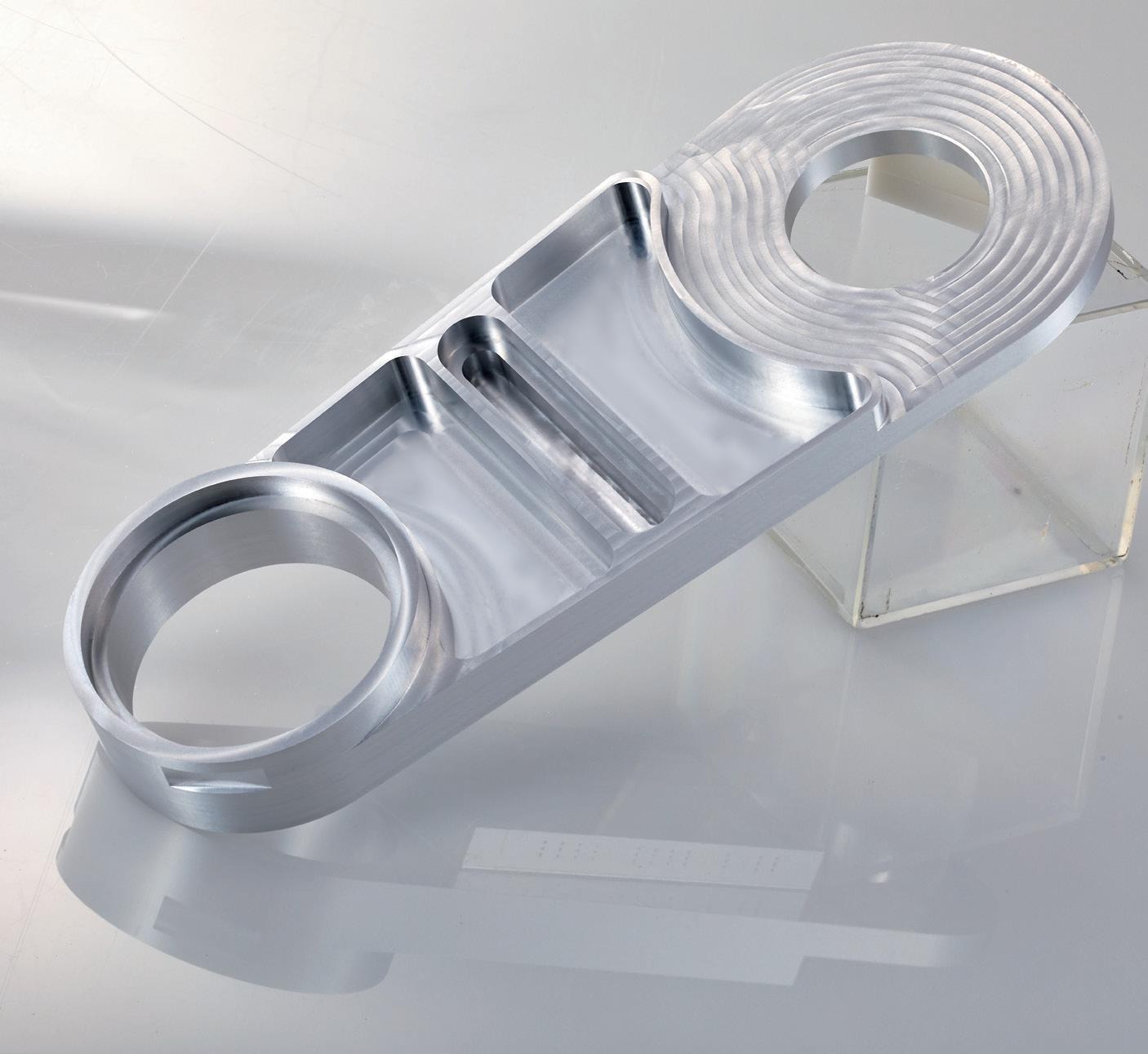
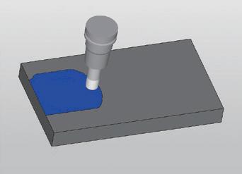
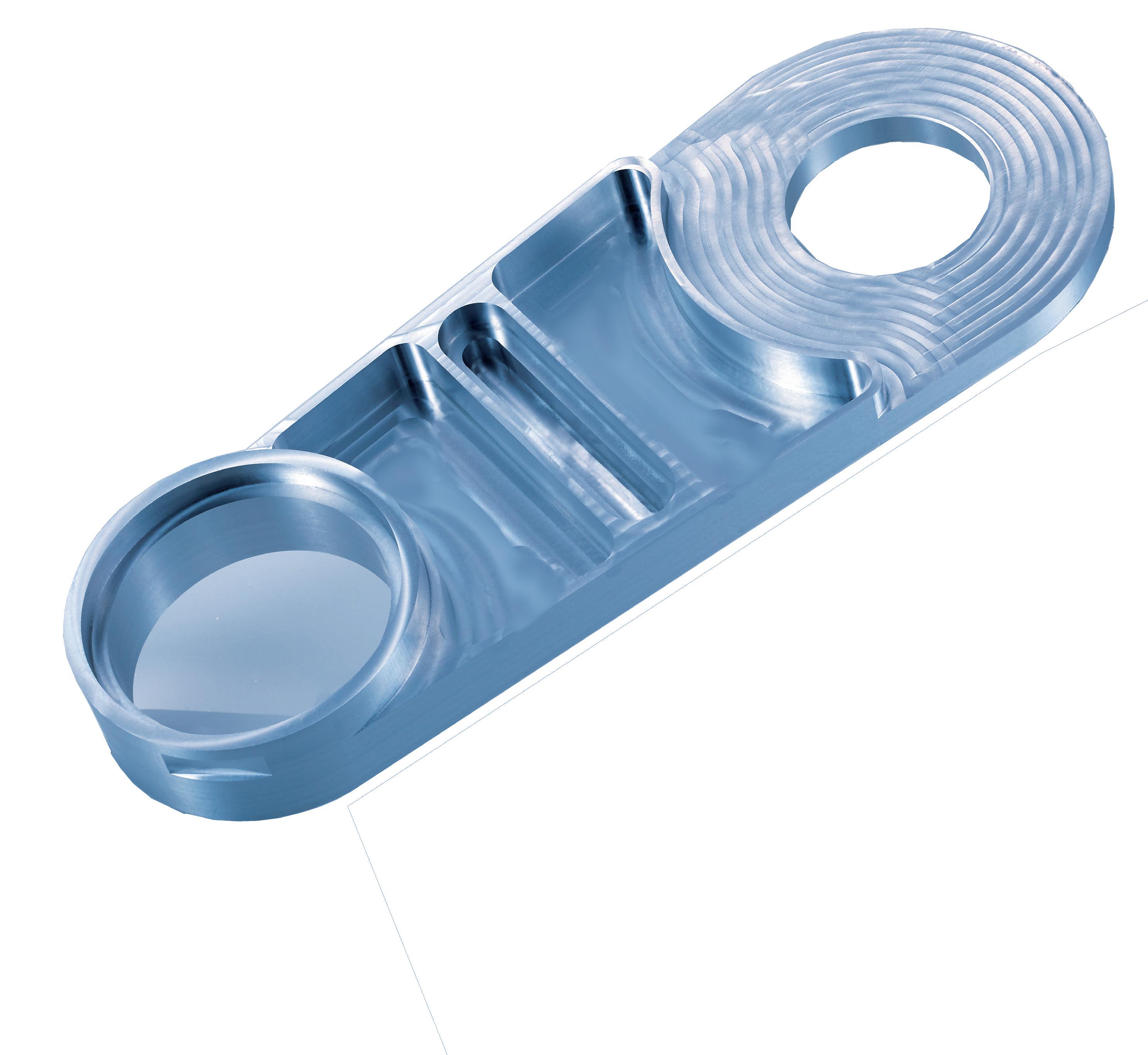
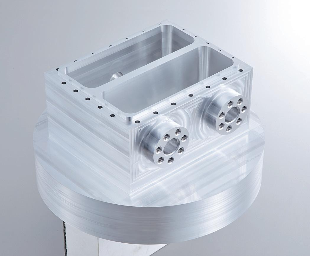
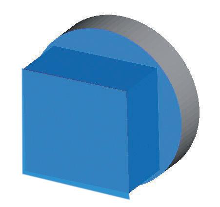
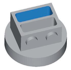
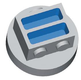
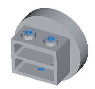
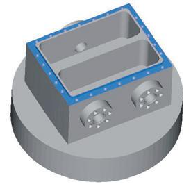
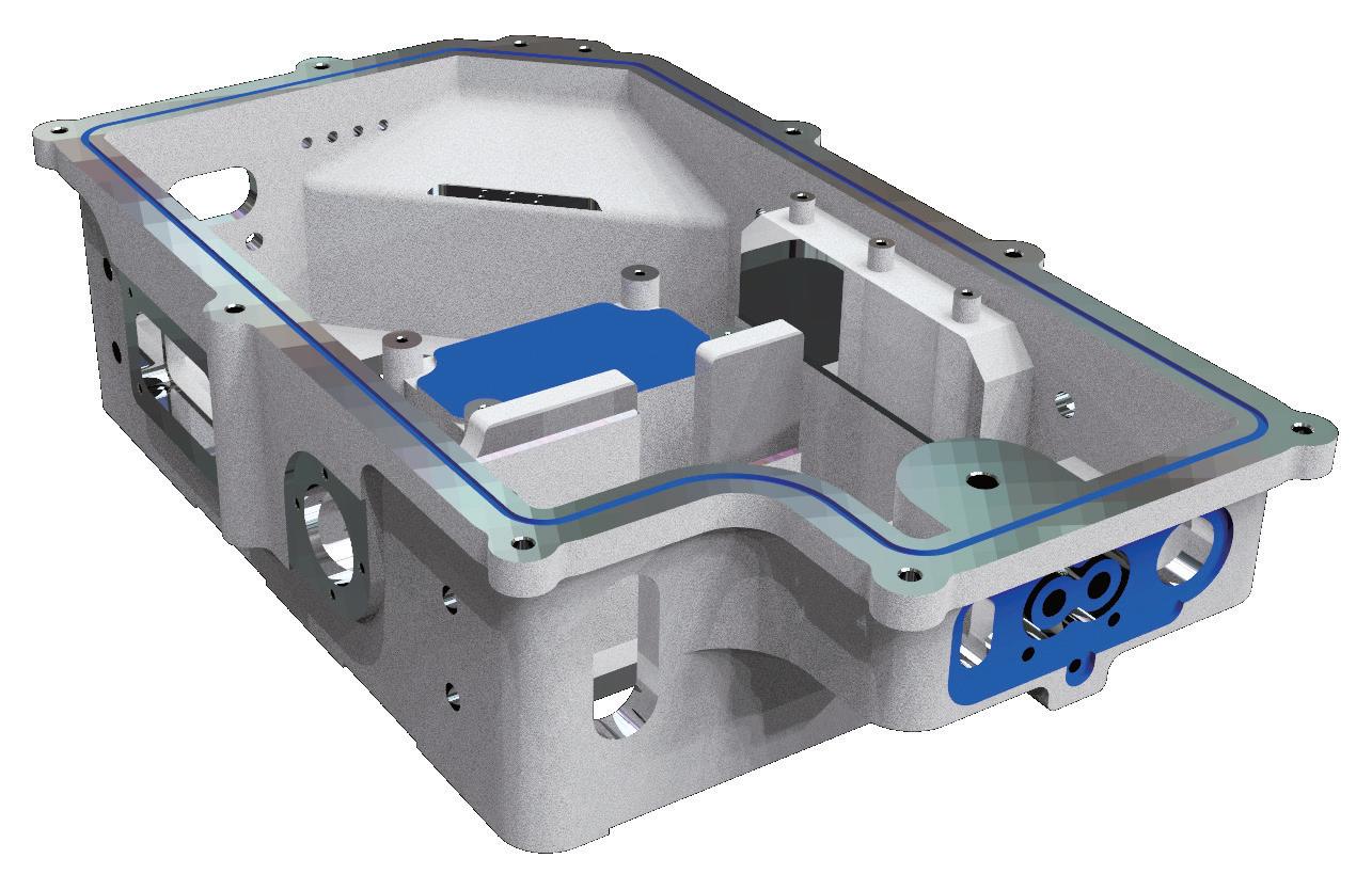
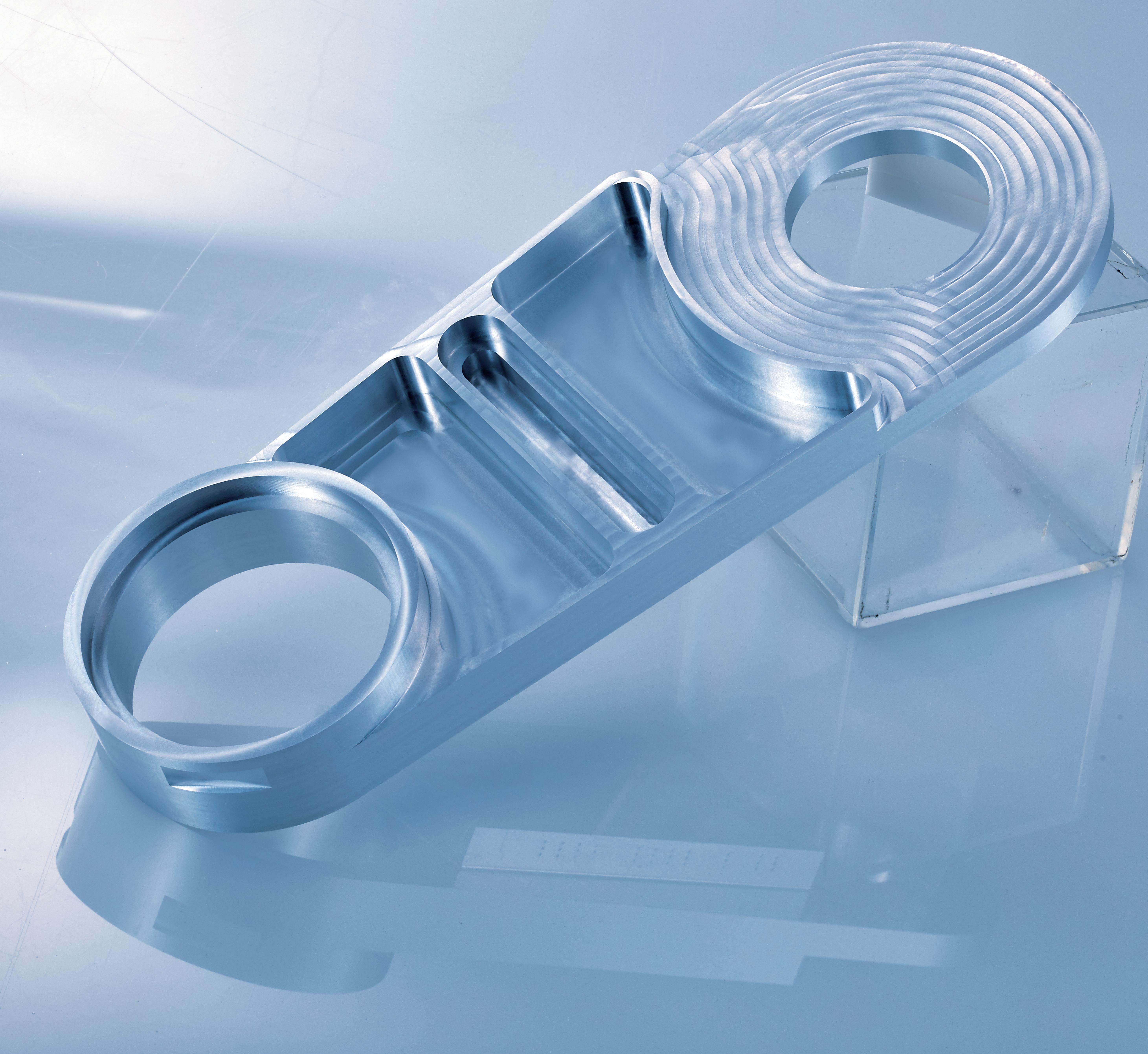
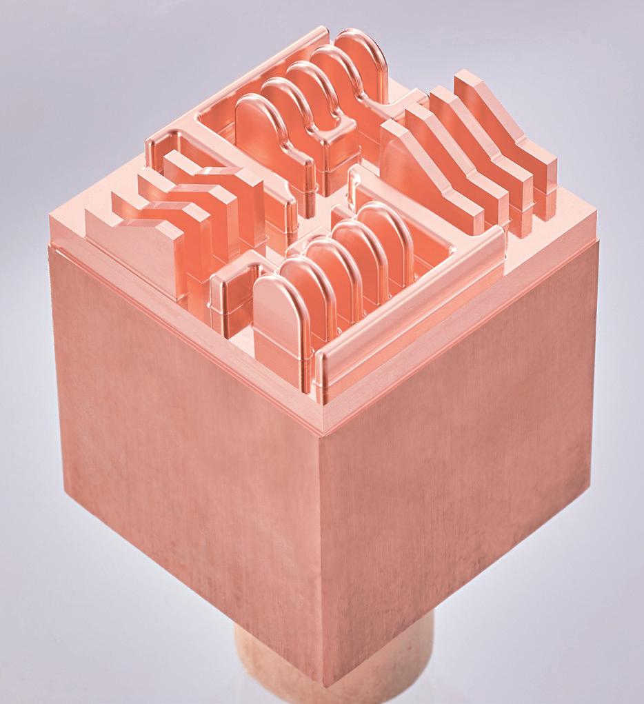
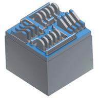
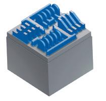
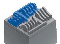
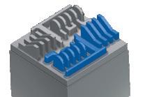
Part Name Vacuum Chamber
Work Material A5056
Machine 5 axis Machining center
Main Spindle HSK-A63
Coolant MQL
However, water-soluble coolant is used for threading and drilling
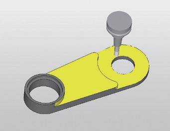
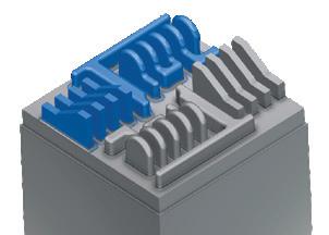
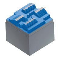
① Top and Side Roughing Finishing
② Side Convex Part Roughing Finishing
③ Side Roughing Finishing
PFAL04R100M25.4-8 Ø100
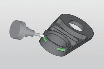
AE-VTFE-N Ø12 (L/D=5.5 66mm)
AE-VTFE-N Ø12 (L/D=8 96mm) ④ ○、○ Pocket Roughing
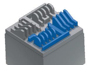
AE-TS-N Ø20×60 Bottom Finishing ⑤ ○ Pocket Semi-finishing Finishing
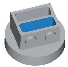
AE-VTFE-N Ø12 (L/D=5.5 66mm) ⑥ ○ Pocket Semi-finishing・Finishing
Helical Milling
⑦ Side Convex Part
AE-TL-N Ø12×60
AE-VTFE-N Ø12 (L/D=5.5 66mm) Counterboring
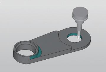
Chamfering
PLDS11R002SS16-90 Ø14.4×90°
M8×1,25 Threading AT-2 R-SPEC M8×1.25 6.2×16 P1.25 INT
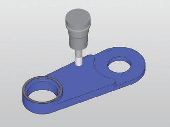
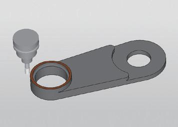
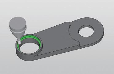
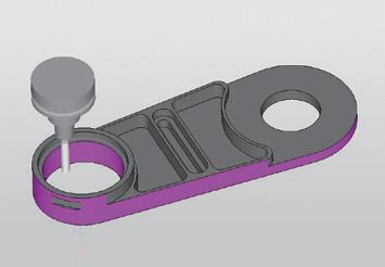
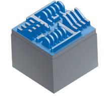
⑧ Seal Surface Roughing・Finishing
AE-VTS-N Ø10×30
Drilling NF-GDN Ø5
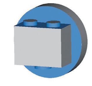
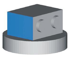
Part Name Inverter Case
Work Material AC4C
Machine SPEEDIO series
Main Spindle BT30
Coolant Water-Soluble
Cooperation : BROTHER INDUSTRIES, LTD.
Introduction of a part of the machining process
List of tools used
ADO-SUS-3D
Ø63
Head: PXAL 200C20-03R000 Ø20
Holder: PXMZ-C200SS20-S120
Head: PXAL 200C20-03R000 Ø20
Holder: PXMZ-C200SS20-S120
AE-VTS-N Ø10×30
AE-VML Ø12×48-N
AE-TS-N Ø3×9
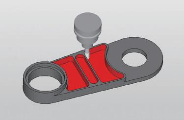
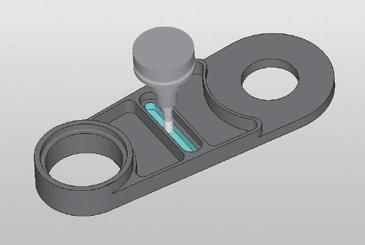
Slot Milling
P2D3000BT30M09 Ø30 Special
AE-VTS-N Ø10×30
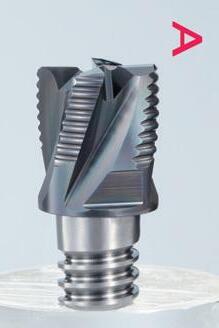
High-efficiency thread mill with end-cutting edge for non-ferrous metals
High-efficiency machining in which 4 processes are completed in a total of 8 minutes and 30 seconds Useful for preventing shifting of cutting position in cast hole
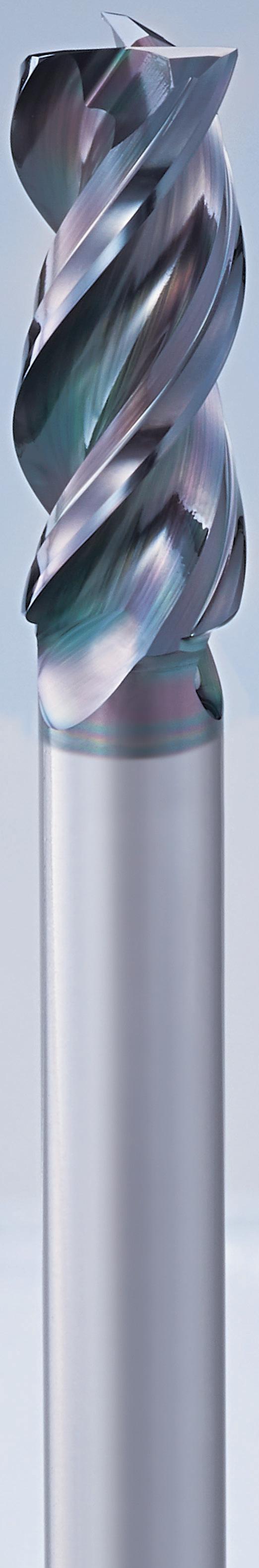
1 Cutting edge specification that achieves both rigidity and sharpness. Achieves high durability and good surface finish
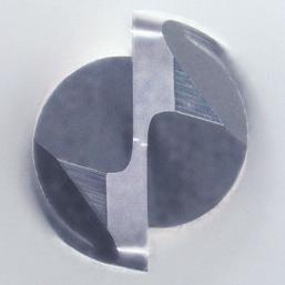
2 New flute form. Facilitates excellent chip evacuation.
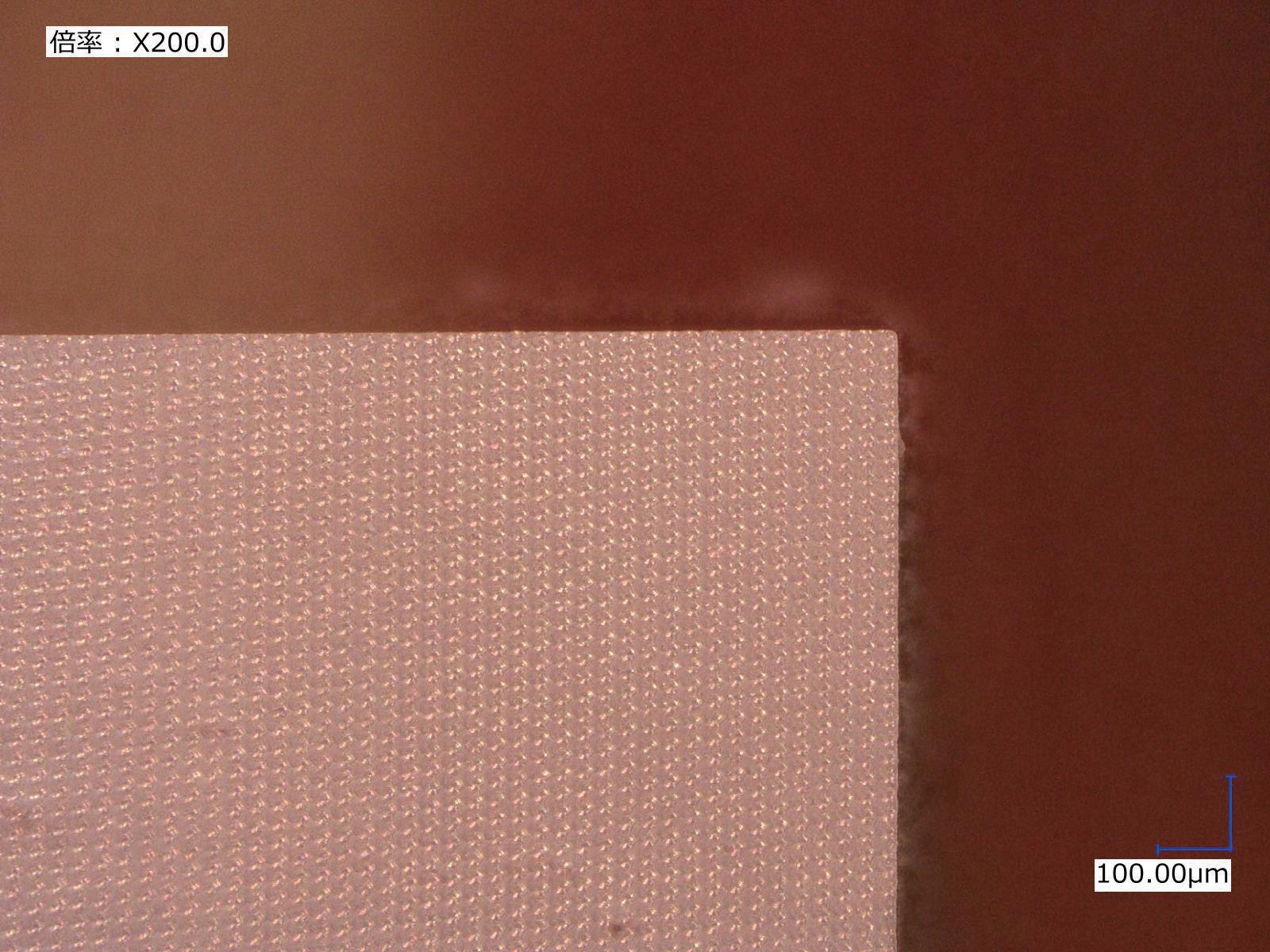
Due to the smoothness of the coating surface, it is extremely effective for non-ferrous materials such as aluminum alloys that require welding resistance and lubricity. Furthermore, its excellent sharpness and ability to suppress burrs enable superior surface finish.
High rigidity prevents chattering
Can be used for plunging
Rigidity is enhanced by increasing the core thickness, which enables the suppression of chattering. By adopting an optimal flute form, high rigidity can be maintained while ensuring trouble-free chip evacuation.
Arrow: indicates chip discharge direction
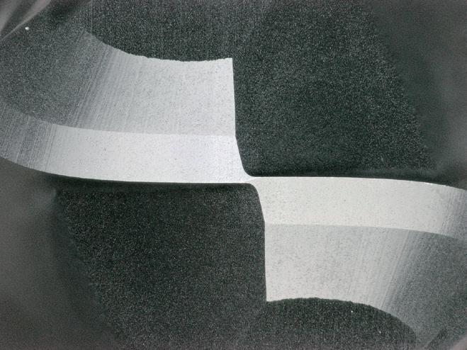
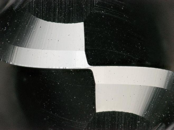
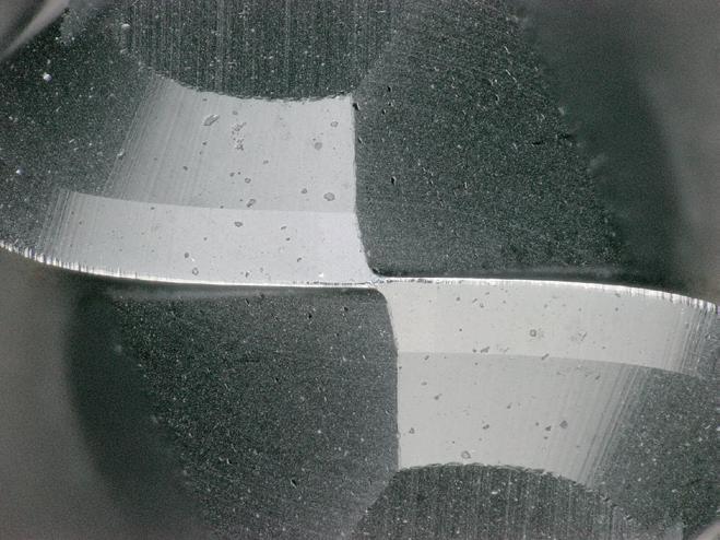
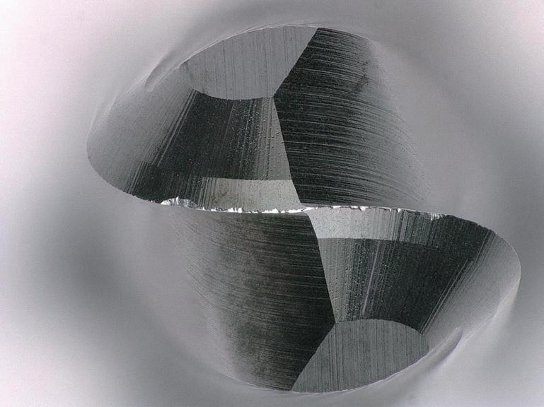
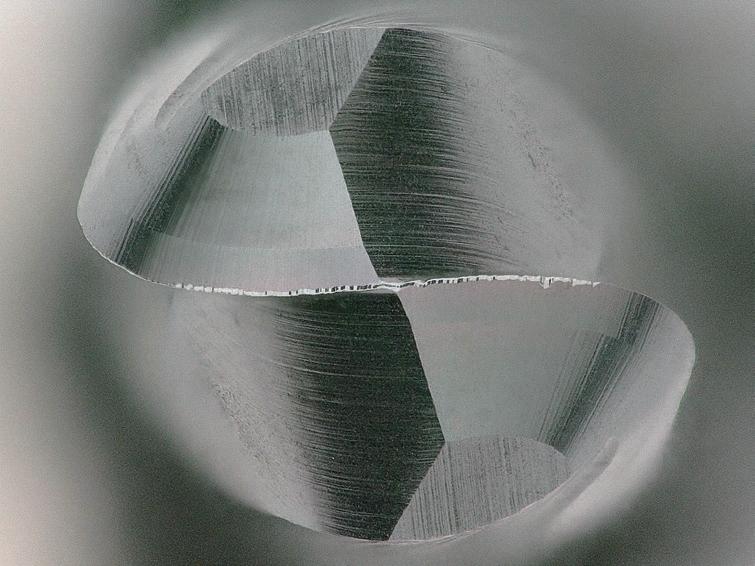
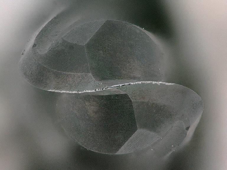
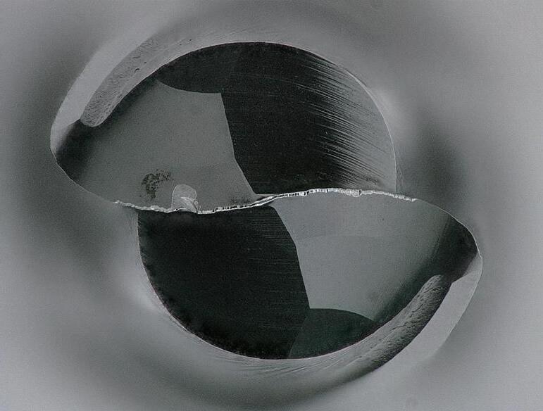
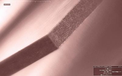
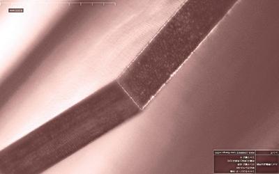
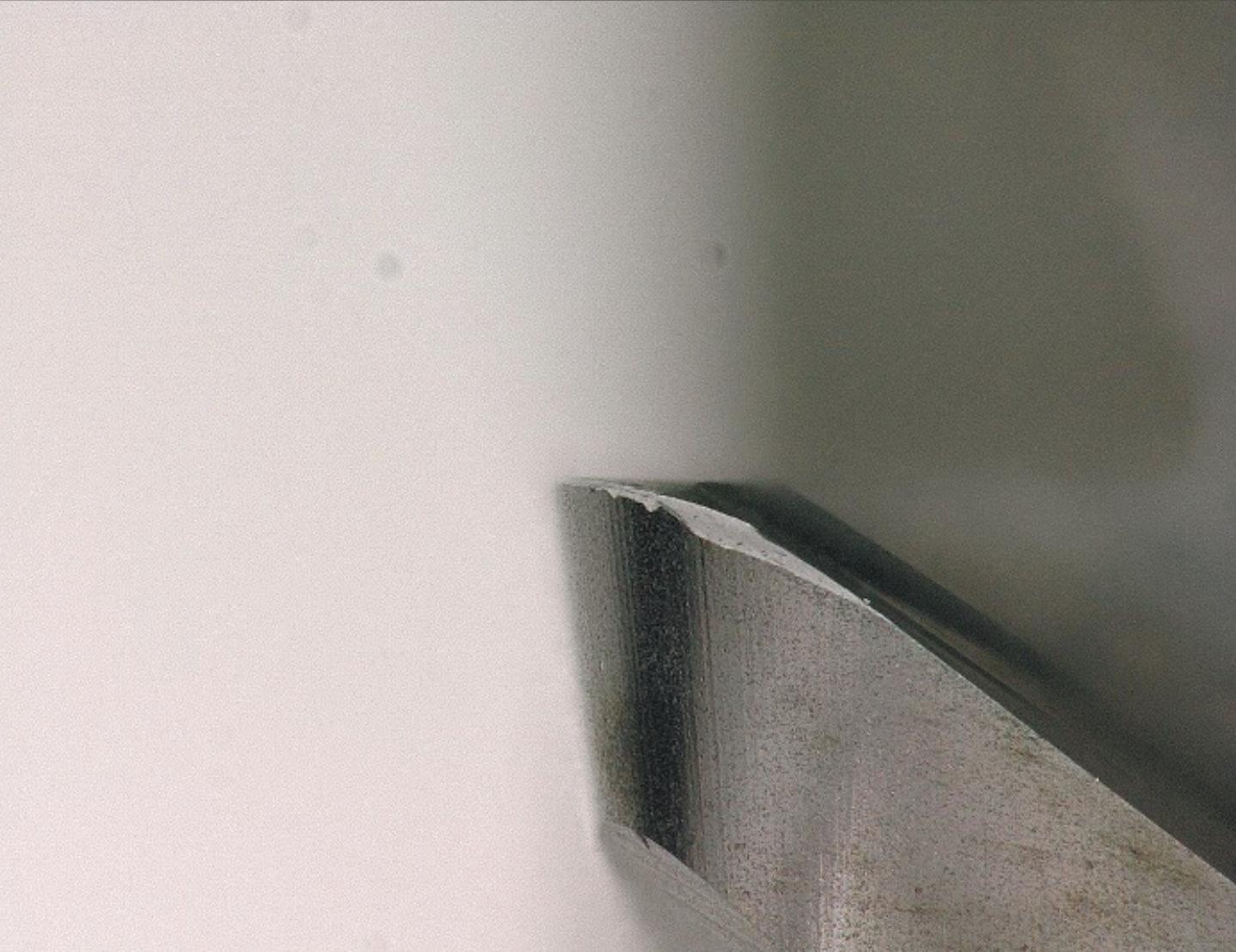
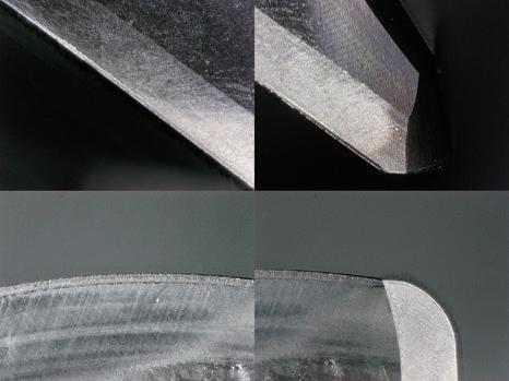
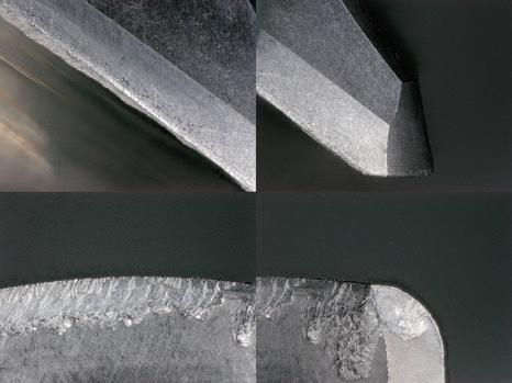
High welding resistance
By adopting the DLC coating, high welding resistance is achieved even with air blow.
Cutting edge condition after milling 11 m
Competitor
Material A7075
Milling Method Slot Milling Cutting Speed
Depth of Cut ap =10mm
Coolant AirBlow
Machine Vertical Machining Center

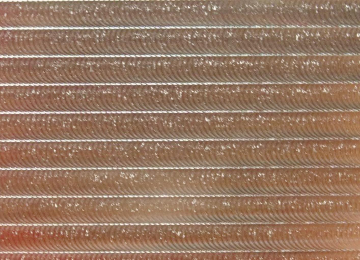
Effects by the combination of DLC coating and unique cutting edge specification for non-ferrous metal machining
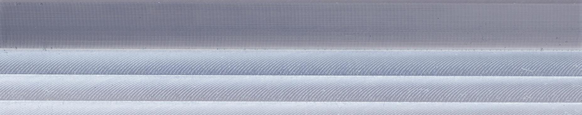
Achieves good machined surface quality.
Good machined surface *Machined
X 2 Times
Side roughness at the initial stage of machining
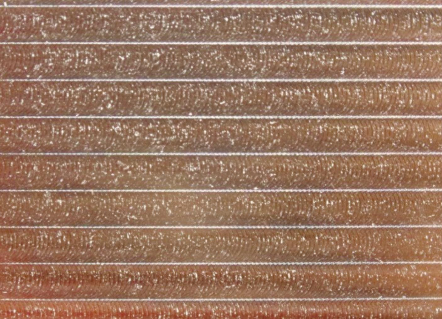
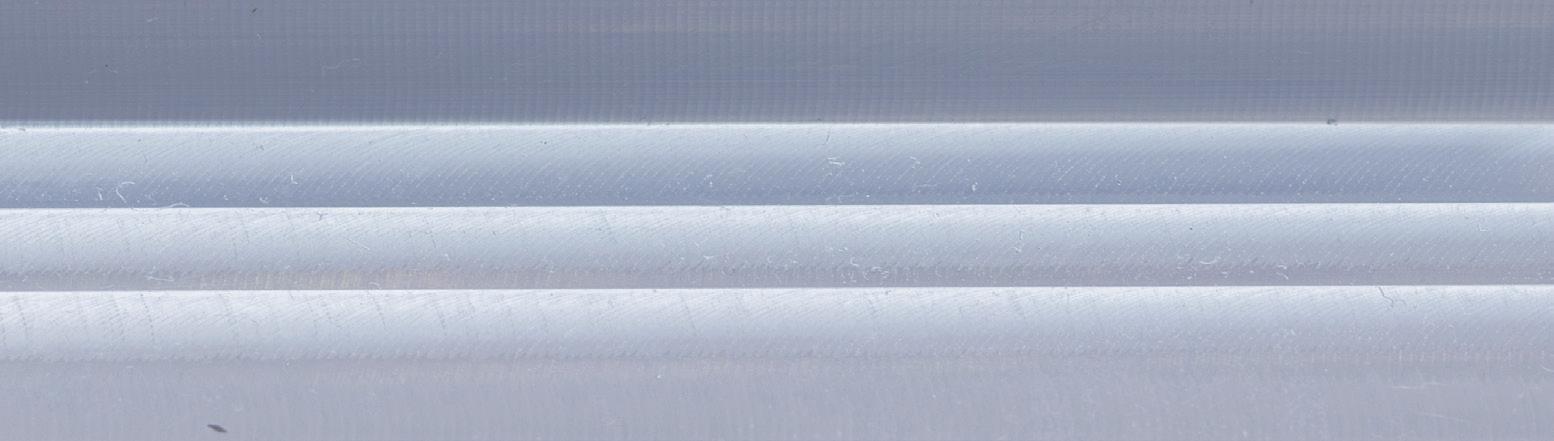
The radius type is effective in improving the machined surface quality of the bottom surface.
Bottom roughness at the initial stage of machining

Q First choice in quality and performance
Q Carbide end mill with DLC coating
Q For non-ferrous materials
Q 3 flutes, short length of cut
Q First choice in quality and performance
Q Carbide end mill with DLC coating
Q For non-ferrous materials
Q 3 flutes, short length of cut
Q Sharp corner for milling 90° corner
The sharp corner edge type is designed without a gash land cutting edge specification, enabling it to mill straight corners.
Effective corner milling with no uncut residue left behind.

Q First choice in quality and performance
Q Carbide end mill with DLC coating
Q For non-ferrous materials
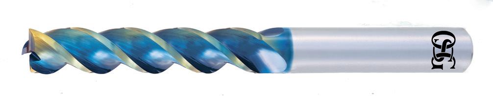
Q 3 flutes, long length of cut
Q First choice in quality and performance
Q Carbide end mill with DLC coating
Q For non-ferrous materials
Q 3 flutes, long length of cut
Q Sharp corner for milling 90° corner
The sharp corner edge type is designed without a gash land cutting edge specification, enabling it to mill straight corners.
Effective corner milling with no uncut residue left behind.
1. The above milling condition is a guideline for the overhang length is 4×D.
2. Use a rigid and precise machine and holder.
3. The indicated speeds and feeds are for milling with water-soluble coolant.
4. Please adjust the speed and feed when the cutting depth is large or when machines with low rigidity are used.
5. Reduce speed and feed as well as depth of cut when high precision is required.
6. Adjust the speed and feed accordingly when the overhang length is longer than specified (refer to p.10).
7. Please always use the appropriate cutting fluid recommended by the cutting fluid manufacturer in the machining of magnesium alloys. Be cautious with the cutting chips
and may pose a serious fire risk if not properly handled.
1. The above milling condition is a guideline for the overhang length is 4×D.
2. Use a rigid and precise machine and holder.
3. The indicated speeds and feeds are for milling with water-soluble coolant.
4. Please adjust the speed and feed when the cutting depth is large or when machines with low rigidity are used.
5. Reduce speed and feed as well as depth of cut when high precision is required.
6. Adjust the speed and feed accordingly when the overhang length is longer than specified (refer to p.10).
7. Please always use the appropriate cutting fluid recommended by the cutting fluid manufacturer in the machining of magnesium alloys. Be cautious with the cutting chips as they are highly flammable and may pose a serious fire risk if not properly handled.
5
Depth of cut
1. The above milling condition is a guideline for the overhang length is 4×D.
2. Use a rigid and precise machine and holder.
3. The indicated speeds and feeds are for milling with water-soluble coolant.
4. Please adjust the speed and feed when the cutting depth is large or when machines with low rigidity are used.
5. Reduce speed and feed as well as depth of cut when high precision is required.
6. Adjust the speed and feed accordingly when the overhang length is longer than specified (refer to p.10).
7. When the chips wind around the end mill, reduce the speed and feed.
8. Please always use the appropriate cutting fluid recommended by the cutting fluid manufacturer in the machining of magnesium alloys. Be cautious with the cutting chips as they are highly flammable and may pose a serious fire risk if not properly handled.
3XD Cutting length
8
1. Use a rigid and precise machine and holder.
2. The indicated speeds and feeds are for milling with water-soluble coolant.
3. Please adjust the speed and feed when the cutting depth is large or when machines with low rigidity are used.
4. Reduce speed and feed as well as depth of cut when high precision is required.
5. Please always use the appropriate cutting fluid recommended by the cutting fluid manufacturer in the machining of magnesium alloys. Be
and may pose a serious fire risk if not properly handled.
Side Milling
5. Please always use the appropriate cutting fluid recommended by the cutting fluid manufacturer in the machining of magnesium alloys. Be cautious with the cutting chips as they are highly flammable and may pose a serious fire risk if not properly handled. AE-TL-N Applies to square/sharp corner edge/radius type Slot Milling
1. Use a rigid and precise machine and holder.
2. The indicated speeds and feeds are for milling with water-soluble coolant.
3. Please adjust the speed and feed when the cutting depth is large or when machines with low rigidity are used.
4. Reduce speed and feed as well as depth of cut when high precision is required.
AE-TL-N Applies to square/sharp corner edge/radius type
3XD Cutting length
1. Use a rigid and precise machine and holder.
2. The indicated speeds and feeds are for milling with water-soluble coolant.
3. Please adjust the speed and feed when the cutting depth is large or when machines with low rigidity are used.
4. Reduce speed and feed as well as depth of cut when high precision is required.
5. When the chips wind around the end mill, reduce the speed and feed.
6. Please always use the appropriate cutting fluid recommended by the cutting fluid manufacturer in the machining of magnesium
and may pose a serious fire risk if not properly handled.
5XD Cutting length
Side Milling
1. Use a rigid and precise machine and holder.
2. The indicated speeds and feeds are for milling with water-soluble coolant.
3. Please adjust the speed and feed when the cutting depth is large or when machines with low rigidity are used.
4. Reduce speed and feed as well as depth of cut when high precision is required.
5. Please always use the appropriate cutting fluid recommended by the cutting fluid manufacturer in the machining of magnesium alloys. Be cautious with the cutting chips as they are highly
and may pose a serious fire risk if not properly handled.
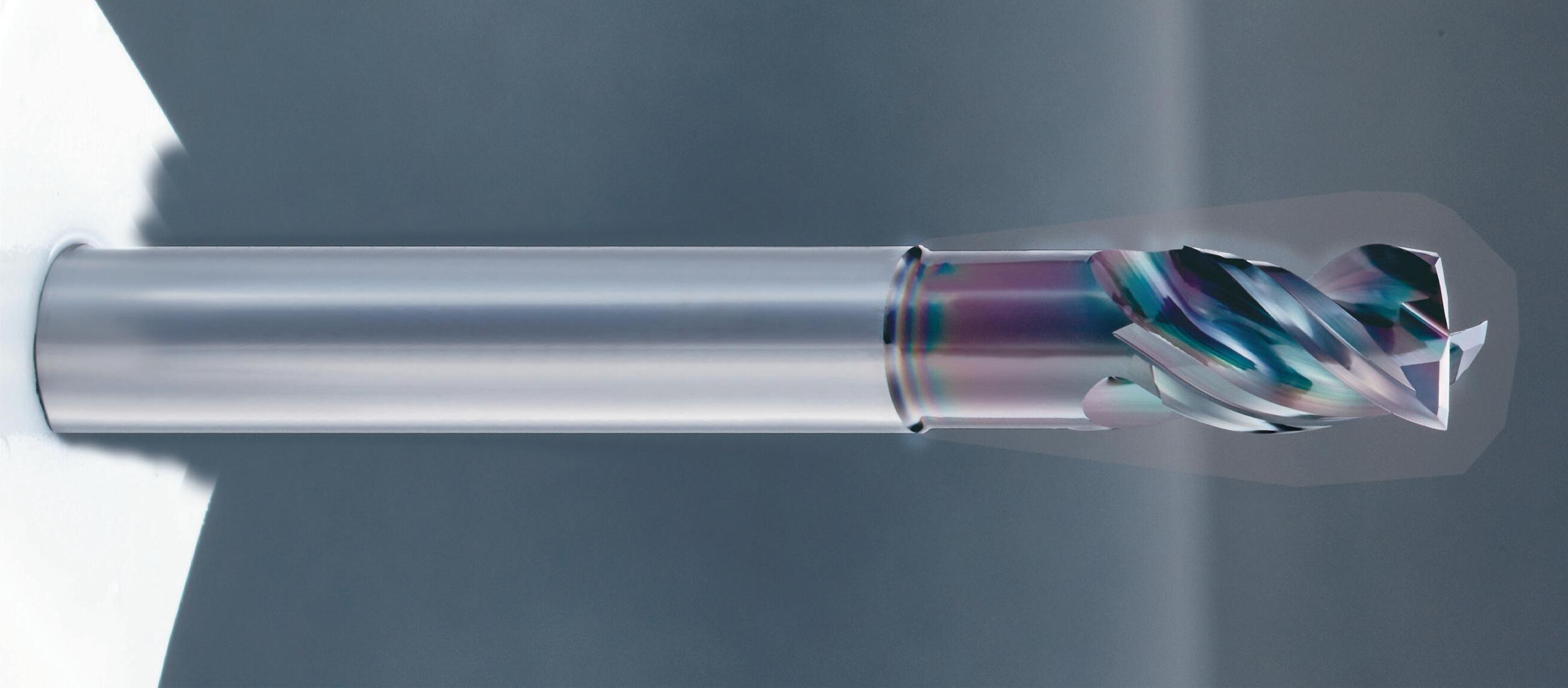
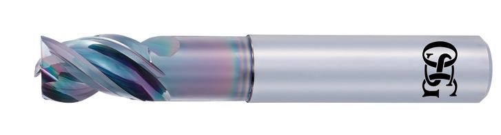
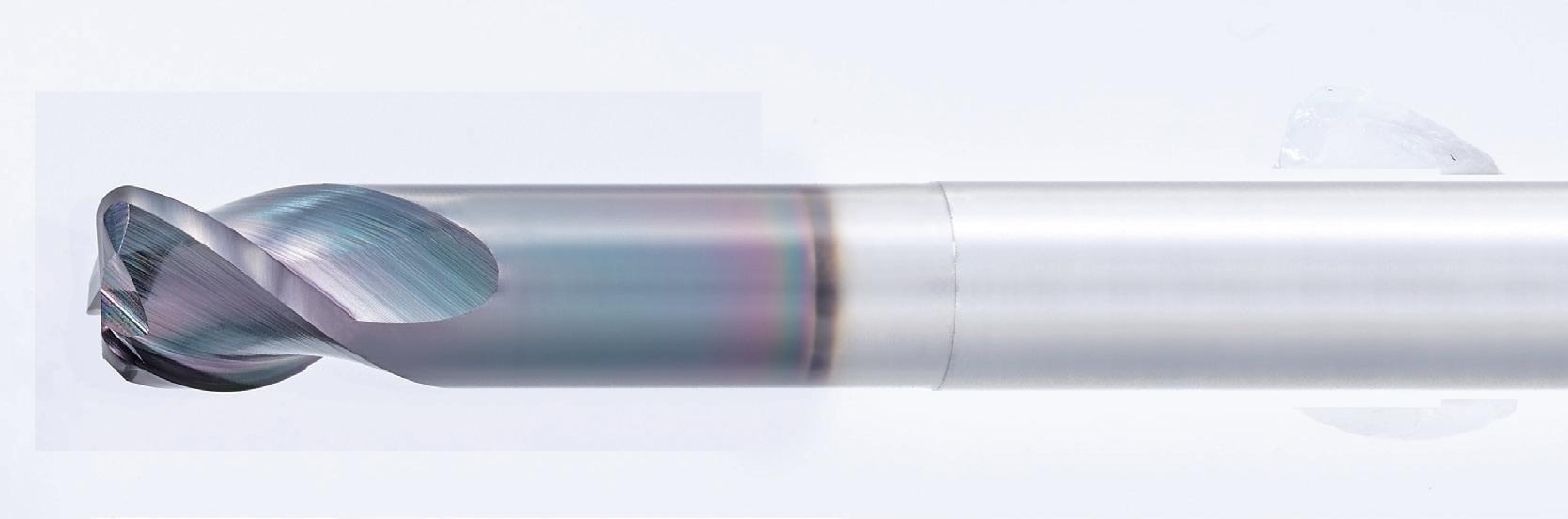
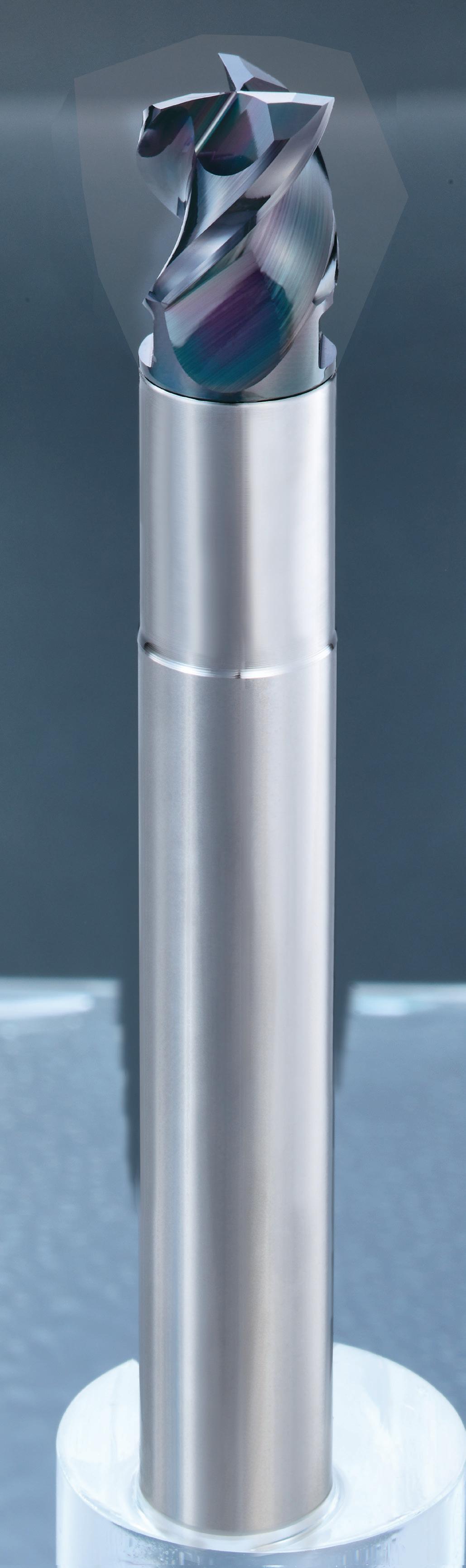
1 Variable lead and unequal spacing teeth
2 Stable and high efficiency milling is made possible by the suppression of chattering
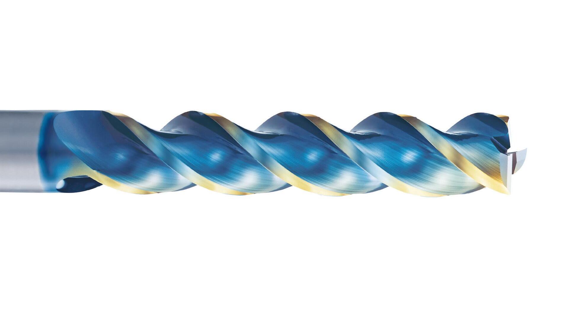
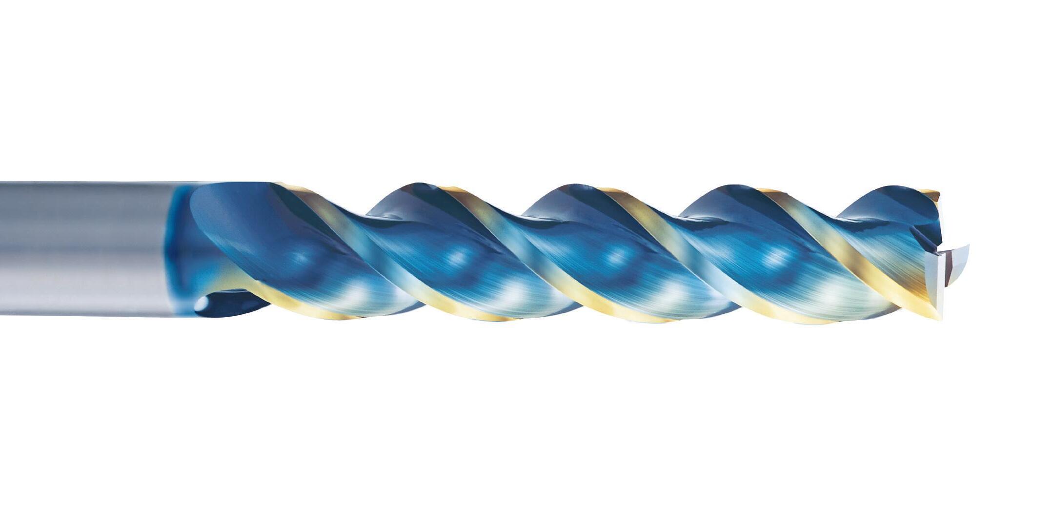
3 DLC-IGUSS Coating
Due to the smoothness of the coating surface, it is extremely effective for non-ferrous materials such as aluminum alloys that require welding resistance and lubricity. Moreover, tool durability is also improved.
Stable and high efficiency milling is made possible by the suppression of chattering
Achieves higher precision machined surface quality
Can be used for plunging
The cutting load is equalized among the cutting edges with greater stability to enable high speed milling*
*Effective for plunging and ramping
Variable lead and unequal spacing teeth geometry enable stable and high efficiency milling
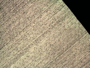
Due to the effect of the DLC coating and the flat cutting edge specification, excellent machined surface quality is achieved.
Surface roughness after milling 11 m
Work Material A7075
Milling Method Slot Milling
Cutting Speed 300m/min (9.550min-1)
Feed 1.432mm/min(0.05mm/t)
Depth of Cut ap =10mm
Coolant Water Soluble
Machine Vertical Machining Center (BT40)
Due to the anti-welding effect of the DLC coating, the anti-vibration effect of the variable lead and unequal spacing teeth geometry, and the effect of the flat cutting edge specification, good machined surface can be achieved even under aggressive cutting condition. Tool
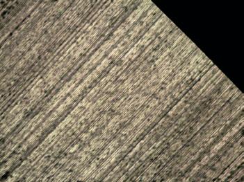
Bottom roughness at the initial stage of machining
Work Material A7075
Milling Method Slot Milling
Depth of Cut ap =10mm
Coolant Water Soluble
Machine Vertical Machining Center (BT40)
Q First choice in quality and performance
Q Carbide end mill with DLC-IGUSS coating
Q For non-ferrous materials
Q 3 flutes, variable helix and unequal spacing
Q First choice in quality and performance
Q Carbide end mill with DLC-IGUSS coating
Q For non-ferrous materials
Q 3 flutes, variable helix and unequal spacing
Q Sharp corner for milling 90° corner
The sharp corner edge type is designed without a gash land cutting edge specification, enabling it to mill straight corners.
Effective corner milling with no uncut residue left behind.
Side Milling
7. Please always use the appropriate cutting fluid recommended by the cutting fluid manufacturer in the machining of magnesium alloys. Be cautious with the cutting chips as they are highly flammable and may pose a serious fire risk if not properly handled. AE-VTS-N Applies to square/sharp corner edge/radius type Slot Milling
1. The above milling condition is a guideline for the overhang length is 4×D.
2. Use a rigid and precise machine and holder.
3. The indicated speeds and feeds are for milling with water-soluble coolant.
4. Please adjust the speed and feed when the cutting depth is large or when machines with low rigidity are used.
5. Reduce speed and feed as well as depth of cut when high precision is required.
6. Adjust the speed and feed accordingly when the overhang length is longer than specified (refer to p.18).
flammable and may pose a serious fire risk if not properly handled. AE-VTS-N
1
1. The above milling condition is a guideline for the overhang length is 4×D.
2. Use a rigid and precise machine and holder.
3. The indicated speeds and feeds are for milling with water-soluble coolant.
4. Please adjust the speed and feed when the cutting depth is large or when machines with low rigidity are used.
5. Reduce speed and feed as well as depth of cut when high precision is required.
6. Adjust the speed and feed accordingly when the overhang length is longer than specified.
7. When the chips wind around the end mill, reduce the speed and feed.
8. Please always use the appropriate cutting fluid recommended by the cutting fluid manufacturer in the machining of magnesium alloys. Be cautious with the
DC = Ø6, Ø8
as
are
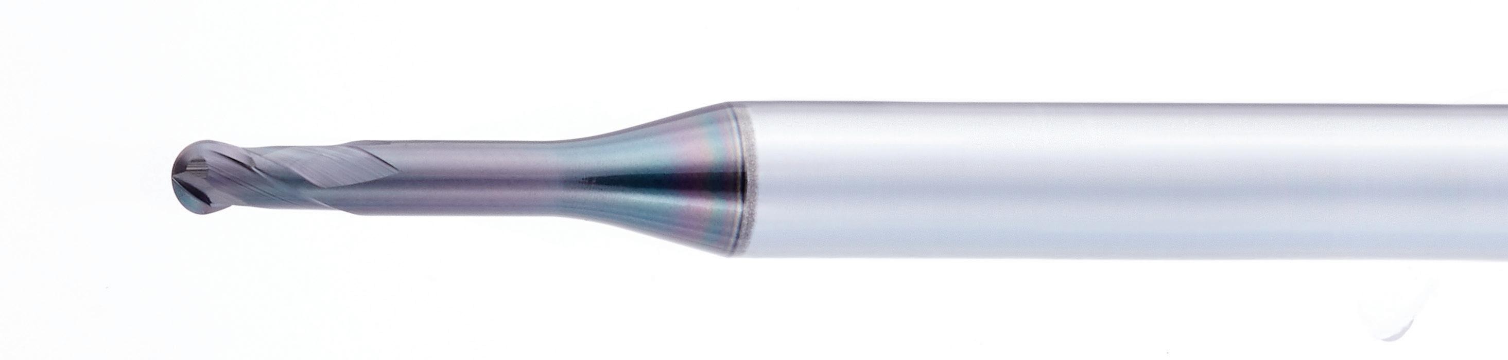
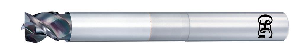
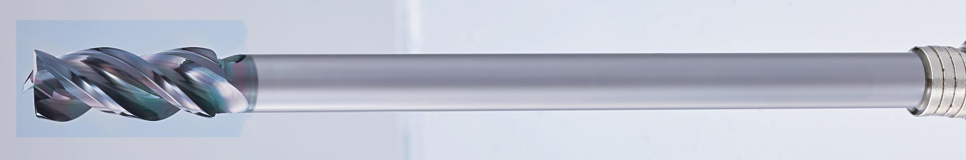
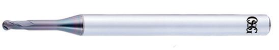
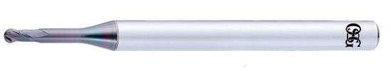
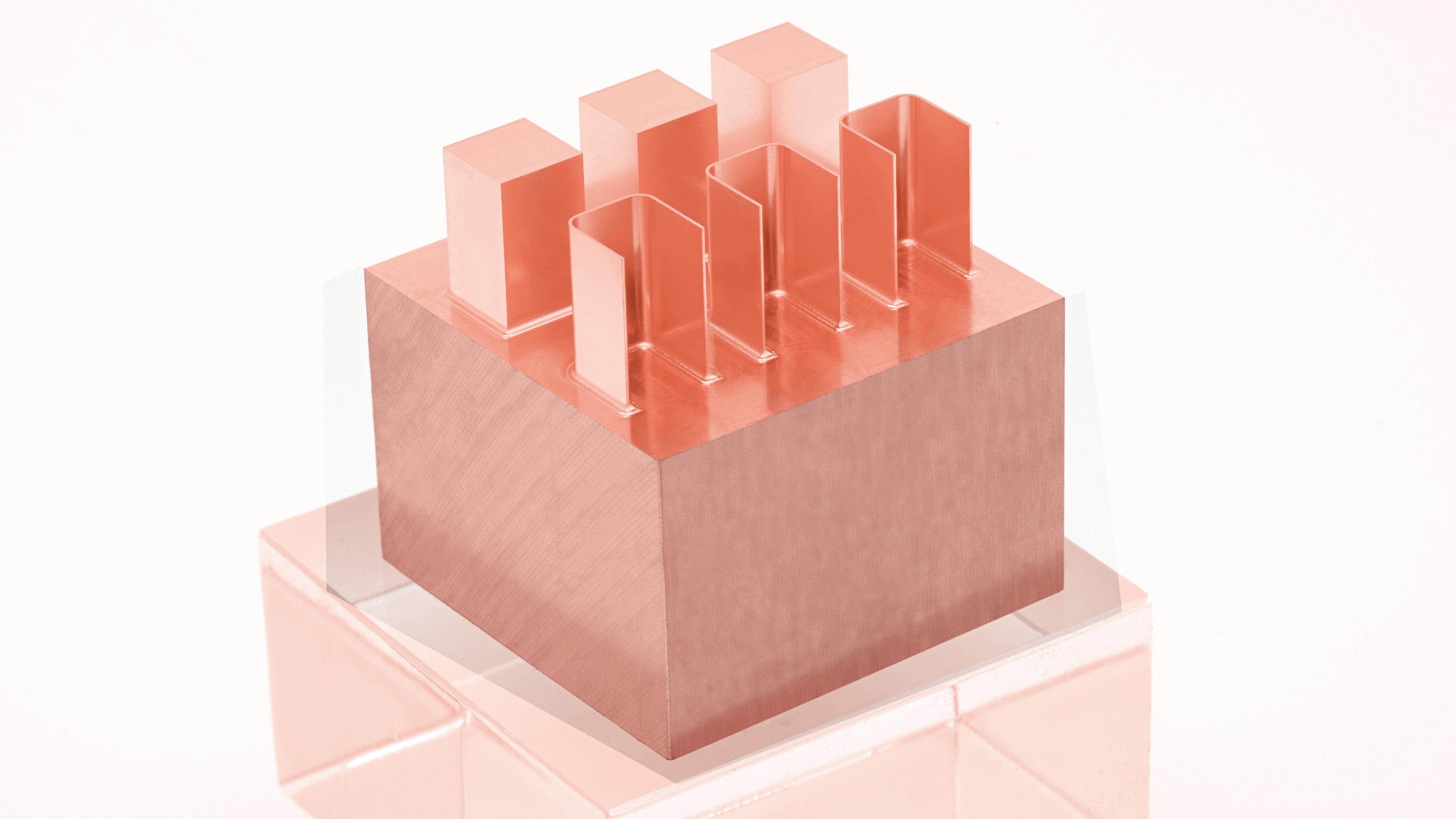
Highly efficient and highly accurate deep side milling at L/D of 5 or more
Highly efficient deep side milling is possible with large step milling of up to 2×D*
The recommended depth of cut varies depending on the overhang length. See p.33 for details.
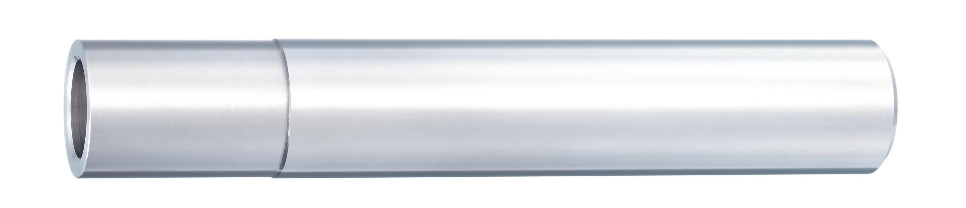
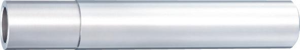
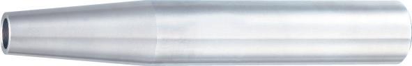
Reduced shank types are tools with an outer diameter that is larger than the shank diameter
Suitable for deep side milling and pocket milling of non-ferrous metal parts
Supports various machining depths by changing the overhang length
Achieves high quality bottom surface milling with long overhang length
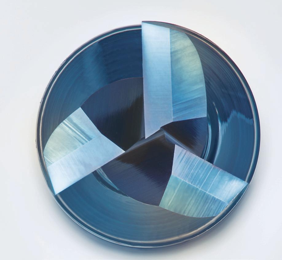
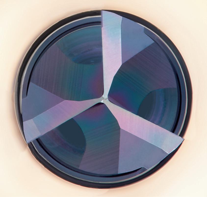
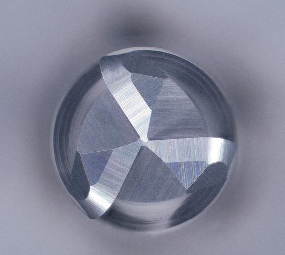
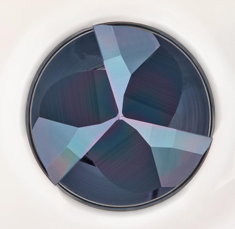
3 cutting edges that connect at the center
The cutting load is equalized among the cutting edges with greater stability
High Milling Quality
Suppresses streak generation
The R shape on the shank side edge suppresses the generation of streaks due to step milling
R shape on the shank side edge
Stable Performance
Suppression of vibration
Variable lead and unequal spacing teeth geometry enable stable and high efficiency milling
Durability
DLC-IGUSS Coating
Due to the smoothness of the coating surface, it is extremely effective for non-ferrous materials such as aluminum alloys that require welding resistance and lubricity. Moreover, tool durability is also improved.
Achieves good accuracy deep side milling at L/D = 8
Tool
Achieves better machining accuracy compared to conventional long type
Comparison of the amount of deflection of the machined surface
The initial stage of machining
The initial stage of machining
Due to the effect of the flat cutting edge specification, excellent machined surface quality is achieved.
Tool
Cutting
200m/min (5.305 min-1)
Feed 1.910mm/min (0,12 mm/t)
Depth of Cut ap = 2,4mm (0,2D)
Overhang
L/D=5 Coolant
roughness at the initial stage of machining
Good machined surface
Milling | Solid carbide
Q First choice in quality and performance
Q Carbide end mill with DLC-IGUSS coating
Q For non-ferrous materials
Q 3 flutes, variable helix and unequal spacing
Q For deep wall milling
Milling | Endmills | Cutting conditions
Depth of cut
1. The above milling condition is a guideline for the overhang length is 5×D.
2. Use a rigid and precise machine and holder.
3. The indicated speeds and feeds are for milling with water-soluble coolant.
4. Please adjust the speed and feed when the cutting depth is large or when machines with low rigidity are used.
5. Reduce speed and feed as well as depth of cut when high precision is required.
6. Adjust the speed and feed accordingly when the overhang length is longer than specified (refer to p.34).
7. When the chips wind around the end mill, reduce the speed and feed.
8. Please always use the appropriate cutting fluid recommended by the cutting fluid manufacturer in the machining of magnesium alloys. Be cautious with the cutting chips as they are highly flammable and may pose a serious fire risk if not properly handled.
AE-VTFE-N Applies to square/radius type
Side Milling
1. The above milling condition is a guideline for the overhang length is 5×D.
2. Use a rigid and precise machine and holder.
3. The indicated speeds and feeds are for milling with water-soluble coolant.
4. Please adjust the speed and feed when the cutting depth is large or when machines with low rigidity are used.
5. Reduce speed and feed as well as depth of cut when high precision is required.
6. Adjust the speed and feed accordingly when the overhang length is longer than specified (refer to p.34).
7. When the chips wind around the end mill, reduce the speed and feed.
8. Please always use the appropriate cutting fluid recommended by the cutting fluid manufacturer in the machining of magnesium alloys. Be cautious with the cutting chips as they are highly flammable and may pose a serious fire risk if not properly handled.
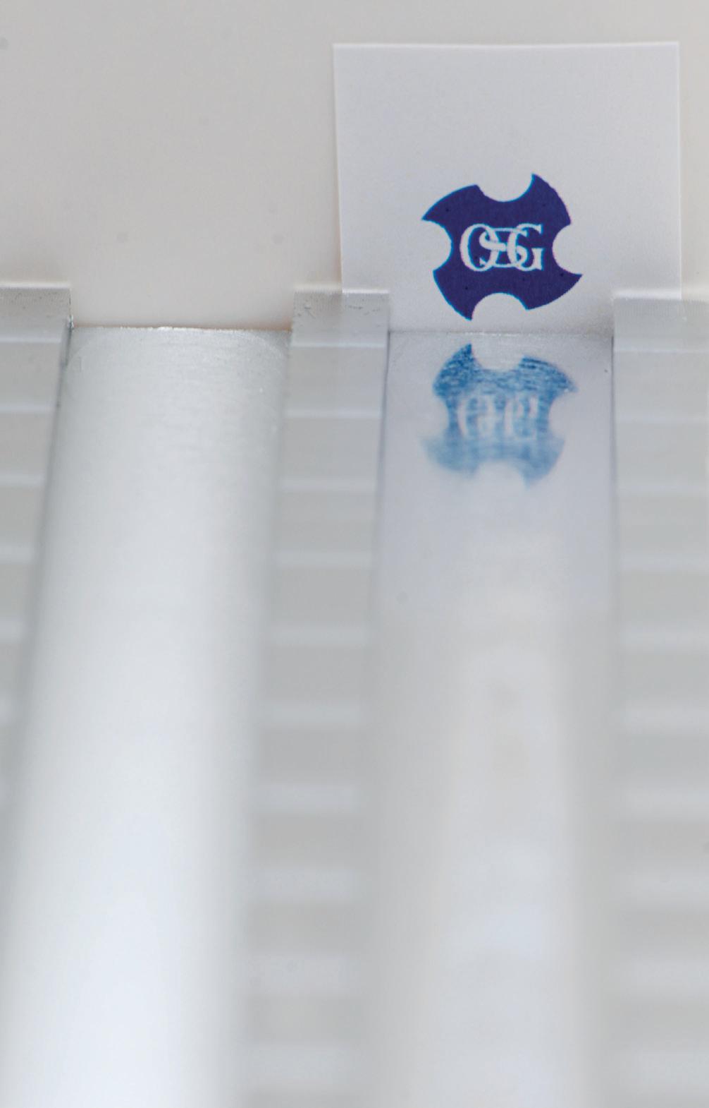
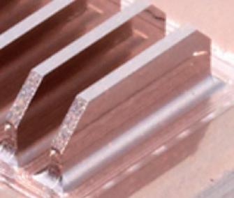
Excellent machined surface accuracy
Beautiful edge without burrs
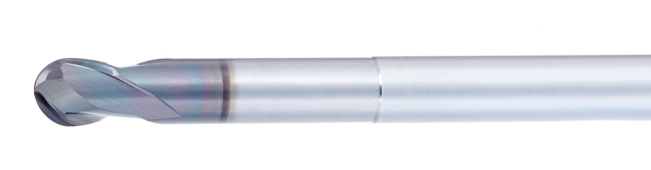
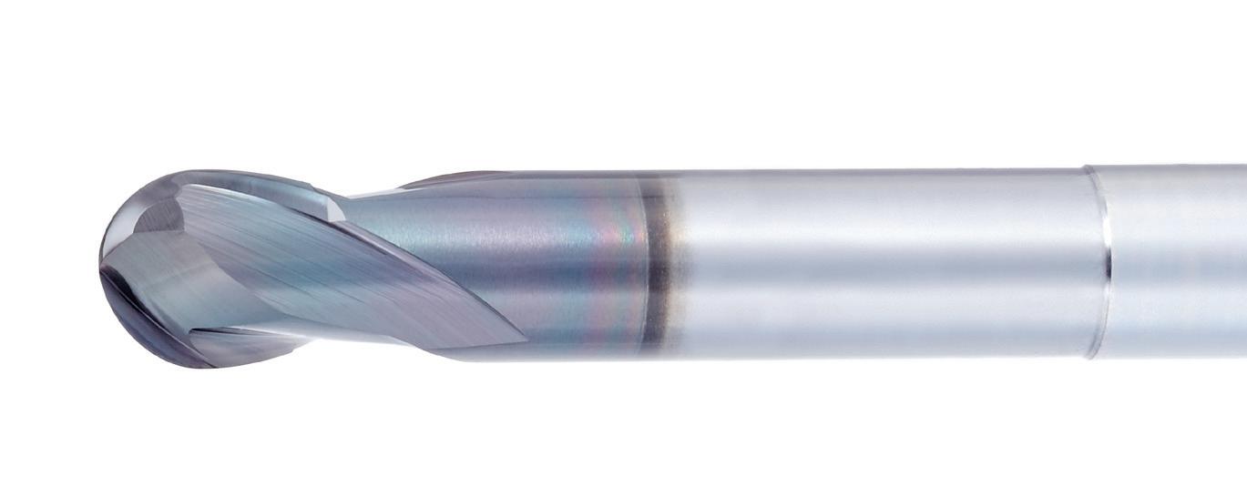
Teardrop-shaped outer periphery
Strong back taper geometry enables milling by point, which prevents chattering and chipping, resulting in improvement of surface accuracy.
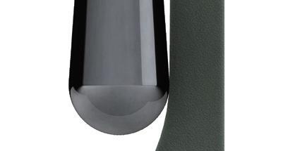
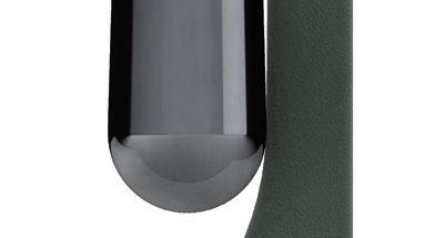
Note: Teardrop-shaped specification does not apply to items above R2. Supports h4 tolerance (0/0,004)
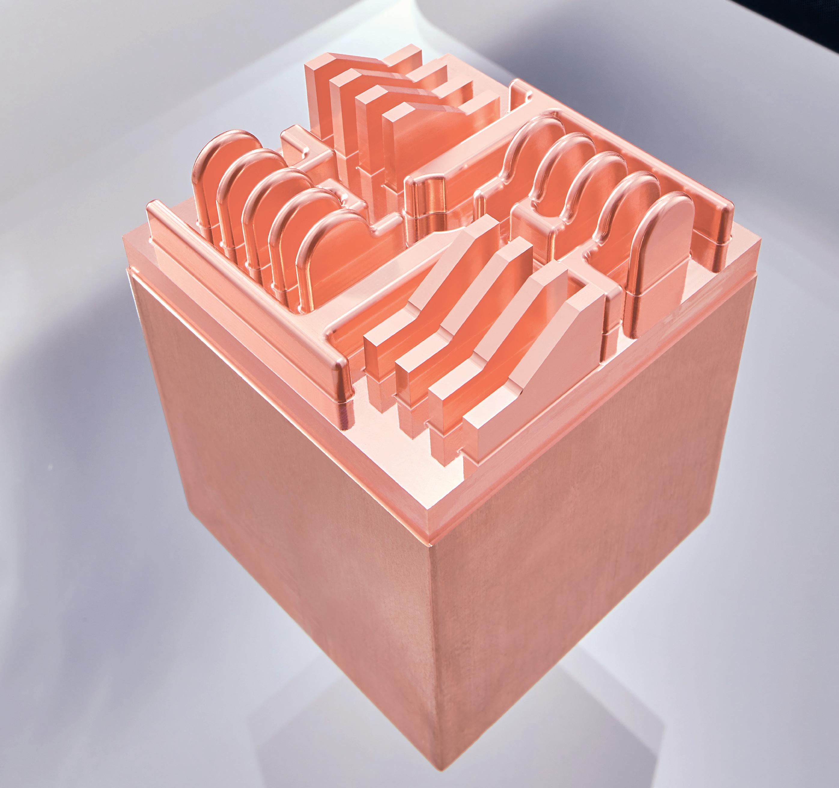
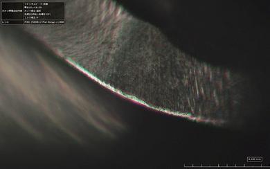
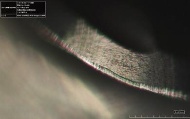
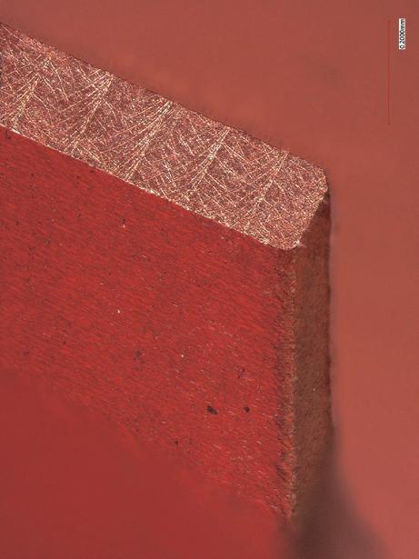
Due to its smooth surface and extremely low coefficient of friction, DLC coating is extremely effective against non-ferrous metals such as copper alloys, which require welding resistance and lubricity.
DLC-IGUSS is effective in suppressing wear against tough-pitch copper (C1100), and stable machining accuracy can be obtained for a long period of time.
Tool 2 Flutes Carbide Ball End Mill
Work Material C1100
Milling Method Pick Milling
Cutting Speed 141m/min (15.000 min-1)
Feed 1.500mm/min (0,05 mm/t)
Depth of Cut ap = 1,5mm Pf = 0,05mm
Coolant Water Soluble
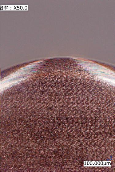
Wear condition of ball flank after milling 420m
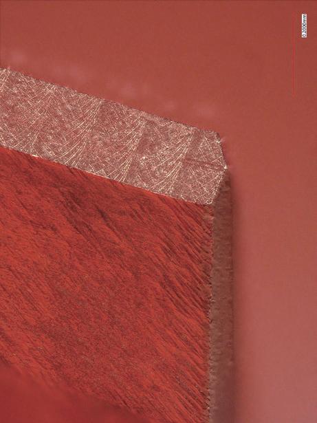
DLC-IGUSS coating enables consistent tool wear
Tool
AE-LNBD-N R1X10X4
Work Material C1100
Milling Method Pick Milling
Cutting Speed
126m/min (20.000 min-1)
Feed 2.000mm/min (0,05 mm/t)
Depth of Cut ap = 0,2mm (0,1D)
Pf = 0,4mm (0,2D)
Coolant Water Soluble
Machine Horizontal Machining Center (BT40)
Wear condition of ball flank after milling 2.480m
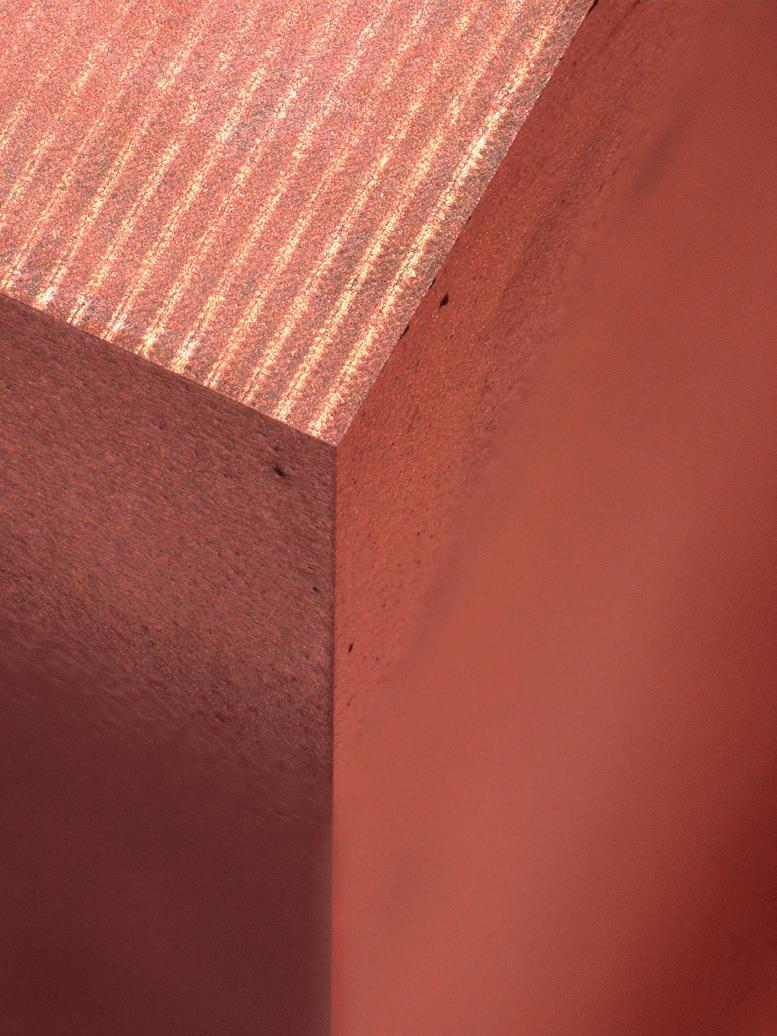
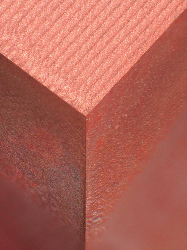
Exhibits superior endurance in copper tungsten
Tool
AE-LNBD-N R1X10X4
Work Material Copper Tungsten
Milling Method Pick Milling
Cutting Speed 101m/min (16.000 min-1)
Feed 1.400mm/min (0,04 mm/t)
Depth of Cut ap = 0,2mm (0,1D)
Pf = 0,4mm (0,2D)
Coolant Water Soluble
Machine Horizontal Machining Center (BT40)
Wear condition of ball flank
Competitor A
B
(C1100)
Work Material : Tough-Pitch Copper
Work Size: 60×60 (Milling Depth 10mm)
(HSK-E32)

Work materials of ① and② are processed under the following cutting conditions
Tool
AE-LNBD-N
R0,2X1X4
Conventional (Cr Coating)
Work Material ① Copper Tungsten
② Tough-Pitch Copper
Milling Method Contour and High Precision Finishing
Cutting Speed
Vc=75m/min (60.000 min-1)
Feed Vf=600mm/min (0,005 mm/t)
Depth of Cut ap = 0,005mm Pf = 0,005mm
Coolant Non-Water Soluble
Machine Android II (HSK-E25)
① Machining Copper Tungsten
Stable wear transition
Work size: 19x19 (milling depth 1mm) Enlarged photo
52,1m Wear comparison after milling 52,1 m
②Machining Tough-Pitch Copper
Good edge without burrs
Stable machining accuracy with little dimensional change
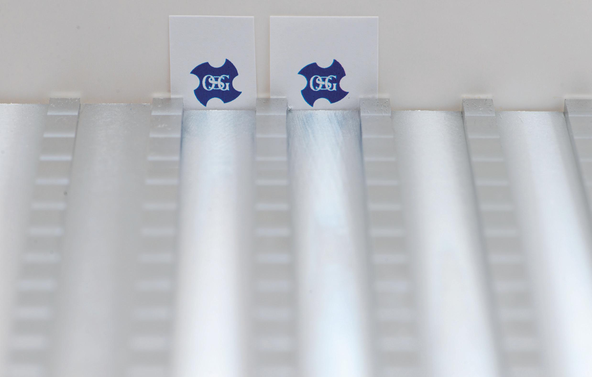
method of cutting test
① Milling 1 set of tough-pitch copper ribs (7 sheets)

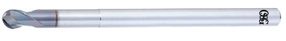
Q First choice in quality and performance
Q Carbide end mill with DLC coating
Q For copper electrodes
Q 2 flutes, long neck, ball nose
Q 72 sizes
Q First choice in quality and performance
Q Carbide end mill with DLC coating
Q For copper electrodes
Q 2 flutes, long neck, ball nose
Q 72 sizes
Milling | Endmills | Cutting conditions
High-efficiency finishing long neck radius type
Achieves high efficiency, long tool life and high precision machining!
Achieves high efficiency milling with 3-flute specification*
*2-flute specification for outer diameter less than 1 mm
Flat cutting edge specification
Achieves higher precision machined surface quality
Flat cutting edge
*Excluding some sizes
Excellent cutting edge diameter accuracy and superior corner radius precision
Excellent cutting edge diameter accuracy
Superior R precision (DC) up to ø 1 0 ~ -0,006 All sizes +/- 0,004 over ø 1 0 ~ -0,01
Abundant variations
Available from outer diameter 0.2 mm to 6 mm with a wide variety of neck lengths
Extension of tool life leads to waste reduction and contributes to resource conservation. Machining efficiency can be improved with the 3-flute specification for outer diameters of 1 mm or more. High-efficiency machining shortens machine operating time and reduces power consumption.
3-flute specification enables high-efficiency machining and long tool life
Tool
Work Material C1100
Milling Method Frontal Milling
Cutting Speed 126m/min (10.000 min-1)
Feed 4.200 mm/min (0,14 mm/t) 2.800 mm/min (0,14 mm/t) V
Depth of Cut ap = 0,3mm ae = 2,4mm
Coolant Water Soluble
Machine Horizontal Machining Center (HSK63)
Wearing condition of the cutting edge after milling 2,079 m

Tool AE-CPR-N 0,5 X R 0,1 X 3
Work Material C1100
Milling Method Frontal Milling
Cutting Speed 55m/min (35.000 min-1)
Feed 640mm/min (0,01 mm/t)
Depth of Cut ap = 0,05mm ae = 0,25mm
Coolant Water Soluble Machine Vertical Machining
DLC coated end mill lineup for non-ferrous metals compatible with copper electrode applications
Standard specification suitable for non-ferrous material processing
DLC-SUPER HARD Coating

High performance type that supports a wide range of applications
DLC-SUPER HARD Coating
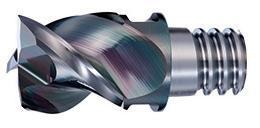
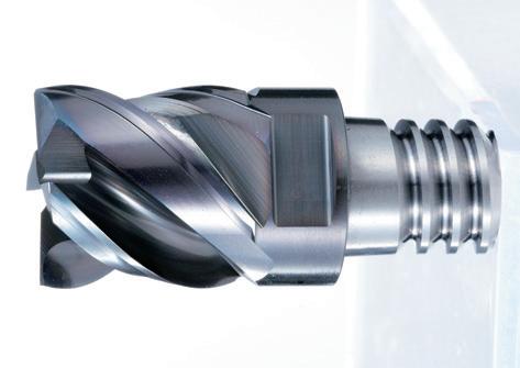
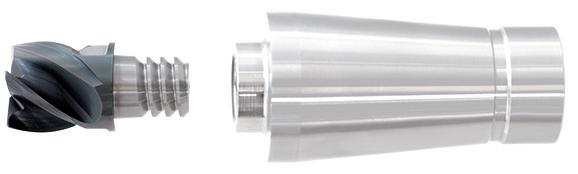
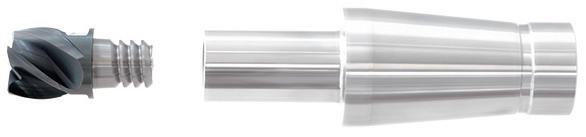
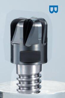
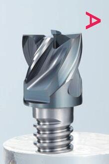
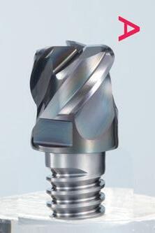
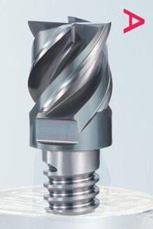
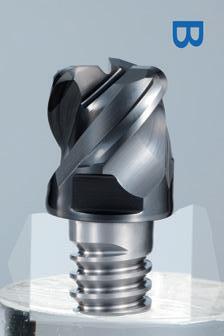
PXM Exchangeable Head End Mill
For Deep Side Milling

Q First choice in quality and performance
Q DLC-IGUSS Coated Carbide End Mill for Copper Electrodes
Q Long neck radius type for high-efficiency finishing
Q 2-3 flutes
Q 144 sizes
Q First choice in quality and performance
Q DLC-IGUSS Coated Carbide End Mill for Copper Electrodes
Q Long neck radius type for high-efficiency finishing
Q 2-3 flutes
Q 144 sizes
DC<1 1≤DC
Q First choice in quality and performance
Q DLC-IGUSS Coated Carbide End Mill for Copper Electrodes
Q Long neck radius type for high-efficiency finishing
Q 2-3 flutes
Q 144 sizes
Q First choice in quality and performance
Q DLC-IGUSS Coated Carbide End Mill for Copper Electrodes
Q Long neck radius type for high-efficiency finishing
Q 2-3 flutes
Q 144 sizes
Milling | Endmills | Cutting conditions
0,2
1
2
2
Milling | Endmills | Cutting conditions
2
2
2
2
2
2
2,5
3
3
3
3
3
3
3
3
3
3
3
3
3
3
3
4
4
4
4
4
4
4
4
4
4
4
4
4
4
6
6
1. Use a rigid and precise machine and holder.
2. Please adjust the speed and feed when the cutting depth is large or when machines with low rigidity are used.
3. Use a water soluble fluid.
4. Use a non-water-soluble cutting fluid if the machined surface and accuracy are of
Adjust
5. Always
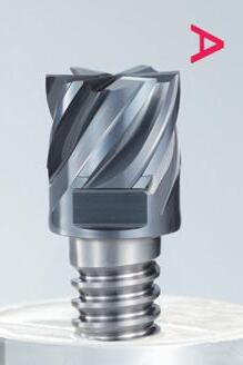
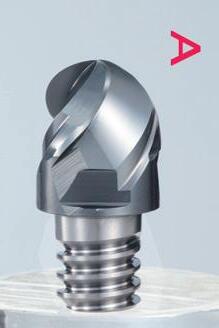
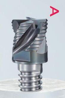
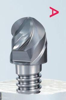
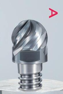
1 Suitable for large-diameter milling with high surface quality
2 Exchangeable Head End Mill PXM for Non-Ferrous Materials
3 DLC-IGUSS Coating
Due to the smoothness of the coating surface, it is extremely effective for non-ferrous materials such as aluminum alloys that require welding resistance and lubricity. Moreover, tool durability is also improved.
Achieves higher precision machined surface quality
High rigidity prevents chattering
Can be used for plunging
By adopting a grade optimal for non-ferrous materials such as aluminum alloy, excellent wear resistance, welding resistance, and long tool life can be achieved.
An abundant lineup including square type, radius type, and reduced shank type are available to accommodate a wide range of applications.
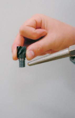
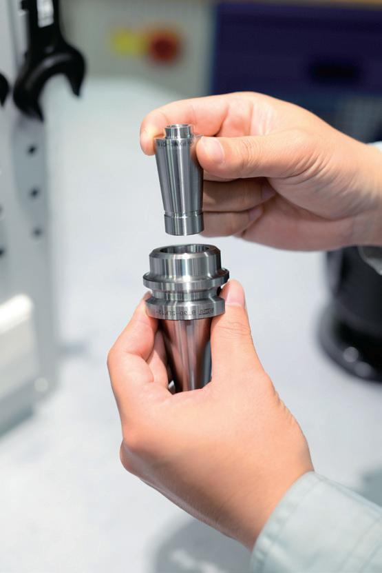
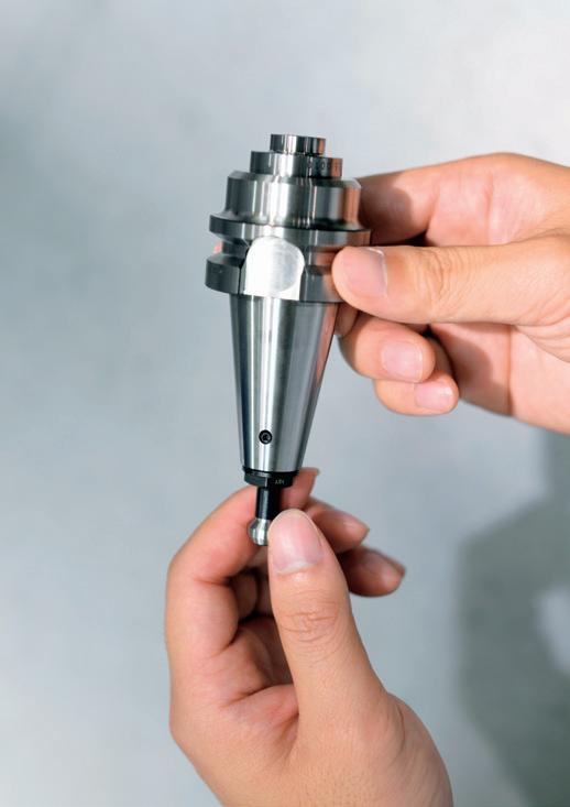
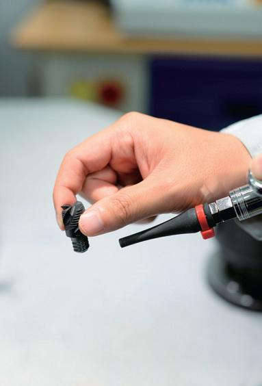
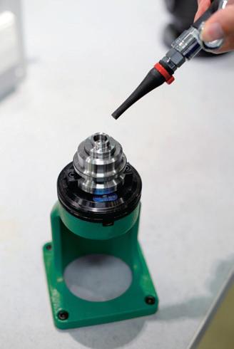
1.
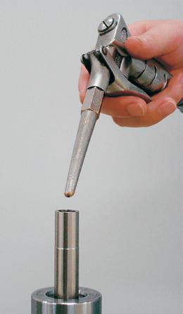
Remove dirt and chips from the connecting
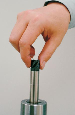
2. Initial
Tighten by hand
gap
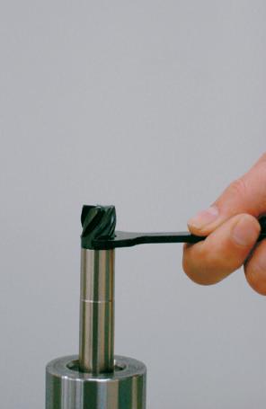
Final
Tighten with a spanner
gap Cautions during use
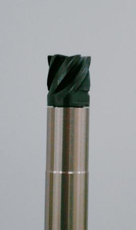
Confirmation Confirm that there is no gap
· Only use the spanner wrenches that are designed specifically for the PXM (P. 13). Please do not use alternative spanner wrenches sold on the market as a replacement.
· Please tighten until the head and the shank holder faces meet. Confirm that there is no gap.
· Degreasing the connecting thread may result in over tightening or a possible separation of the faces. Please do not degrease.
· Please make sure that the spanner wrench is inserted properly and turn it slowly during use.
Improved surface roughness by the effect of the flat cutting edge specification
Tool
Size ØØ16 ØØ16 3 flutes
Work Material A7075
Milling Method Side Milling
Cutting Speed
600m/min (12.000min-1)
Feed 5.400mm/min(0.15mm/t)
Depth of Cut ap =8mm (0,5D) ae=4,8mm (0,3D)
Overhang Length 50mm (L/D= 3,1)
Coolant Water Soluble
Machine Vertical Machining Center (BT40)
Achieves good surface finish regardless of coolant type
Tool
Work Material A7075
Milling Method Side Milling
Cutting Speed 600m/min (12.000min-1)
Feed 2.700mm/min(0.075mm/t)
Depth of Cut ap =8mm (0,5D) ae=4,8mm (0,3D)
Overhang Length 50mm (L/D= 3,1)
Welding suppression by DLC coating
Machine Vertical Machining Center (BT40) Tool
(12.000min-1)
2.700mm/min(0.075mm/t)
Milling Method Side Milling
Milling | Indexable | Heads
Q 3 flutes solid carbide head
Q For Non-ferrous materials
Q For PXMZ straight shank holder
Q 10 - 25 mm
Q Exchangeable carbide/steel body for PXM
Side milling L/D≤3
Side milling 3<L/D≤5
Side milling 5<L/D≤7
Milling | Indexables | Cutting conditions
1. Use a rigid and precise machine and holder.
2. Please adjust the speed and feed when the depth of cut is large or when machines with low rigidity are used.
3. Please adjust the cutting condition when the overhang length is longer.
4. Please consider the overhang length as the total length of replaceable head and overhang length of shank holder.
5. When milling copper and copper alloys, lower the rotational speed by 20 to 40%, feed rate by 50 to 80%, and cutting depth by a p 50 to 80% in accordance with the table above.
6. Please always use the appropriate cutting fluid recommended by the cutting fluid manufacturer in the machining of magnesium alloys. Be cautious with the cutting chips as they are highly flammable and may pose a serious fire risk if not properly handled.
1 Powerful chip evacuation even on small machining center
2 The reduction of overhang length improves rigidity and rotational balance
3
A wide variety of exchangeable heads
· Suitable for steel, stainless steel and aluminum
· Wide processing range from roughing to finishing
4 Greater cost performance compared to monoblock type holders, only need to change the collet in case of trouble.

Remarkable Difference!
All the knowledge and know-how acquired by designing solid carbide end mills are found in these exchangeable heads. ·Various types are available to meet variety of machining methods.
End Face + Taper = Double Face Clamping
·High rigidity and accuracy of tightening
·High precision of run out≤0,015mm
·High head replacing accuracy = ±0.03mm
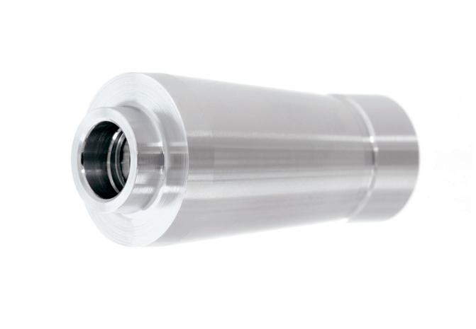
Applying buttress screw makes easy and reduces time to desorb heads
Milling | Indexable | Collets
Q PXMC collet for PHOENIX PXM series.
Q Applicable exchangeable heads: PXNH, PXNL, PXSE, PXSM, PXDR, PXRE, PXBE, PXBM
Q With coolant hole
Q Reducing overhang length allows high rigidity
Milling | Indexable | Holders
Q HY-PRO holder for PXMC
Make sure the fastening portion of the collet is clean then insert it into the holder. Turn the pull stud to
*For models other than BT30 please refer to the
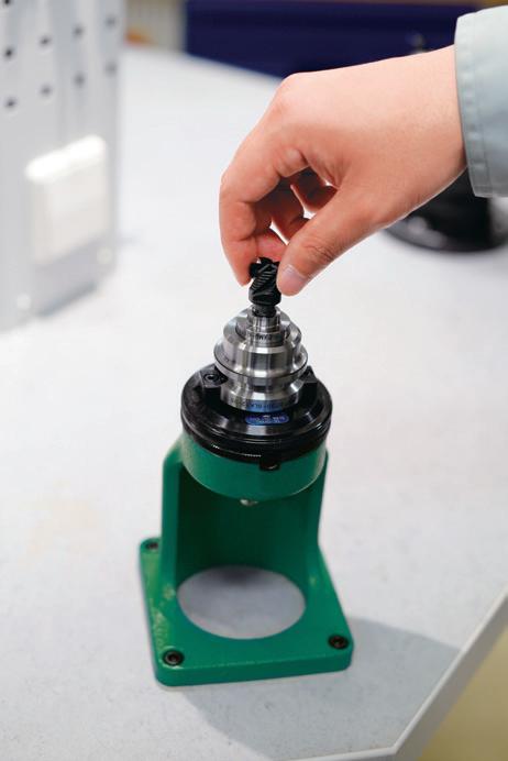

4. Mounting the Head
After screwing the head in by hand, use the PXM spanner wrench to tighten.
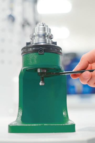
2. Final Tightening
Tighten with a spanner wrench
Remove dirt and chips from the connecting thread and collet
Mounting procedure for holders other than BT30
Insert the hexagon socket wrench into the pull screw hexagonal section.
*For pull studs with holes (φ6 or above), it is operational with the stud being attached.
Cautions during use
To prevent the collet from rotating, support the tip of the collet by hand, tighten with the wrench by turning to the right, then fastening to the required torque.
*Recommended tightening torque: 18N·m
· Only use the spanner wrenches that are designed specifically for the PXM (p.24) for attaching PXM heads . Please do not use alternative spanner wrenches sold on the market as a replacement.
· Please refer to p.24 for tightening torque.
· Please tighten until the head and the collet faces meet. Confirm that there is no gap.
· Degreasing the connecting thread may result in over tightening or a possible separation of the faces. Please do not degrease.
· Please make sure that the spanner wrench is inserted properly and turn it slowly during use.
The PXM is an exchangeable head end mill series with the same high performance of a solid tool and the cost efficiency of an indexable tool. A single exchangeable head body is able to accommodate a wide range of exchangeable heads to meet various application needs.
shapes Please see OSG PHOENIX Catalog for details.


OSG EUROPE LOGISTICS
Avenue Lavoisier 1
B-1300 Z.I. Wavre - Nord - Belgium
Tel: +32 10 23 05 07 info@osgeurope.com
OSG BELUX
Avenue Lavoisier 1
B-1300 Z.I. Wavre - Nord - Belgium
Tel: +32 10 23 05 11 info@osg-belgium.com
OSG FRANCE
Parc Icade, Paris Nord 2
Immeuble “Le Rimbaud” 22 Avenue des Nations CS66191 - 93420 Villepinte - France
Tel: +33 1 49 90 10 10 sales@osg-france.com
OSG NETHERLANDS
Bedrijfsweg 5 - 3481 MG Harmelen
Tel: +31 348 44 2764 info@osg-nl.com
OSG UK
Kelsey Close, Attleborough Fields Ind Est, CV11 6RS, Nuneaton, United Kingdom.
Tel: +44 1827 720 013 uk_sales@osg-uk.com
CZECH, SLOVAKIA, HUNGARY
OSG Europe Logistics S.A. Slovakia organizacna zlozka Racianská 22/A, SK-83102 Bratislava Slovakia
Tel. +421 24 32 91 295 Orders-osgsvk@osgeurope.com
09/2023 - All rights reserved. © OSG Europe 2023.
Tool specifications subject to change without notice.
www.osgeurope.com
OSG POLAND Sp. z.o.o.
Spółdzielcza 57 05-074 Halinów - Poland
Tel: +22 760 82 71 osg@osg-poland.com
OSG GERMANY
Karl-Ehmann-Str. 25
D - 73037 Göppingen - Germany
Tel: +49 7161 6064 - 0
Fax: +49 7161 6064 - 444 info@osg-germany.de
OSG SCANDINAVIA
(For Scandinavian countries) Langebjergvaenget 16
4000 Roskilde - Denmark
Tel: +45 46 75 65 55 osg@osg-scandinavia.com
SWEDEN
Branch office of OSG SCANDINAVIA Singelgatan 7
212 28 Malmö - Sweden
Tel: +46 40 41 22 55 osg@osg-scandinavia.com
OSG IBERICA
Bekolarra 4
E - 01010 Vitoria-Gasteiz - Spain
Tel: +34 945 242 400 osg.iberica@osg-ib.com
OSG TURKEY
Rami Kişla Cad.No:56 Eyüp Istanbul 34056 - Turkey
Tel+90 212 565 24 00
Fax: +90 212 565 44 00 info@osg-turkey.com
OSG ROMANIA SRL
25C, Bucuresti-Magurele Street (Sector 5) 051431 Bucuresti - România
Tel: +40 21 322 07 47 info@osgromania.ro
AUSTRIA
Branch office of OSG GERMANY Messestraße 11 A-6850 Dornbirn
Tel: +49 7161 6064-0 info@osg-germany.de
OSG ITALIA
Via Ferrero, 65 A/B3
I - 10098 Rivoli - Italy
Tel: +39 0117705211 info@osg-italia.it
Vischer & Bolli AG
Machining and Workholding Im Schossacher 17
CH-8600 Dübendorf T +41 44 802 15 15 info@vb-tools.com