15 minute read
4 Setting up for an Inspection


In order to set up for an inspection, you need to: 1. Select a Sensor Type. 2. Acquire a good image. 3. Set parameters depending on the Sensor Type.
4.1 Selecting a Sensor Type
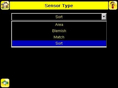
When you exit Demo Mode, the sensor reboots with a single inspection with a Match sensor type by default. To change the Sensor Type: 1. Go to Main Menu > Inspection > Properties > Sensor Type This displays the Sensor Type menu options.
2. Select either Area , Blemish, Match, or Sort. 3. Click the Home Screen icon in the upper-left corner of the screen to return to the Home screen.
4.2 Acquiring a Good Image
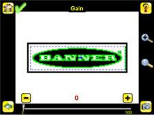
The iVu Series sensor needs to capture a good image of each part to ensure that it correctly passes good parts and fails bad parts. 1. Go to Main Menu > Imager > Auto Exposure to run the Auto Exposure routine. 2. Check the lighting. • Make sure that the lighting is constant and consistent (unchanging over time, no shadows or hot spots). • Capture the shape and form of the target object with lighting that optimizes its contrast and separates it from the background. Depending on the target, this may mean the integral ring light is not the best choice and other Banner lights should be considered. • Adjust the mounting angle to provide the clearest image of the part features you are monitoring. The mounting bracket lets you easily position and adjust the sensor on your line. 3. If needed, go to Main Menu > Imager > Auto Exposure to run the Auto Exposure routine a second time or adjust Gain and Exposure manually: • Main Menu > Imager > Gain
• Main Menu > Imager > Exposure

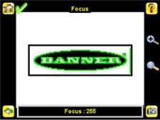
4. Go to Main Menu > Imager > Focus to adjust the focus while monitoring the Focus Number:
For Micro-lens Models Only:
1. Use the supplied 1/16" hex key to loosen the Focusing Window locking screw (D), then adjust focus on the iVu Series sensor using the clear Focusing Window (B). 2. Adjust focus while monitoring the focus number. To ensure the best image, adjust the focus until the Focus Number peaks.
NOTE: Turning the Focusing Window counter-clockwise focuses on closer objects, while turning the Focusing Window clockwise focuses on more distant objects.
3. Once the best image has been acquired, lock the focusing window.
Micro-Lens Models
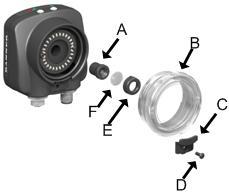
A Lens
B Focusing Window C Locking Clip D Locking Screw E Filter Cap (optional) F Filter (optional)
NOTE: Filter Kits are available separately.
For C-Mount Models Only:
1. Remove the Lens Enclosure 2. Adjust focus while monitoring the focus number. To ensure the best image, adjust the focus until the Focus Number peaks. 3. Replace the Lens Enclosure on the camera.
C-Mount Models
C E
B
D C
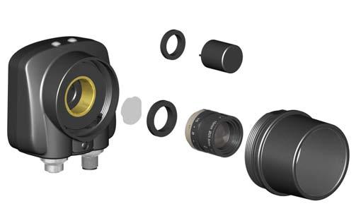
A
A C-Mount Lens
B Lens Enclosure
C Retainer Ring (optional) D Filter (optional) E Filter Retainer Ring Tool
NOTE: Filter Kits are available separately.
4.3 Configuring an Area Sensor
This section describes how to configure an Area sensor using the Demo application as a reference
NOTE: By default, the Trigger is set to Internal, and will continously trigger based on a time interval setting. This may make it more difficult to make adjustments while setting up the sensor. The best practice is as follows: • Go to the Main Menu > Imager > Trigger menu and select External.
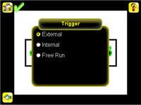
• Make sure there is no external trigger input. • Use the Trigger icon in the lower-right of the screen to manually trigger the sensor to capture an image as you set up and test. • Capture images of a range of samples to set up from the "worst" good part to the "best" bad part.
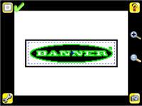
Start the setup with a good part. Normally, each part to be tested will be centered in the Field of View (FOV). 1. Adjust the Region of Interest (ROI).The ROI is a blue-dotted box as shown below.
2. Click Anywhere within the ROI to select it. When selected, the ROI is red with resize and rotational icons in the corners.
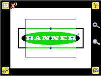

3. Resize and move the ROI so that the feature of interest. Resize the ROI so that it surrounds just the feature of interest. In the
Demo example, the feature of interest is the Banner logo as shown below.
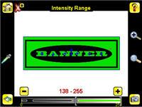
NOTE: When running an Area inspection, the sensor will only find objects within the ROI. 4. Click anywhere outside the ROI to deselect it. 5. Set inspection parameters. • Adjust the Intensity Range parameter. 1. Go to Main Menu > Inspection , and click the Intensity Range option.
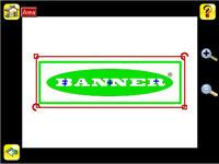
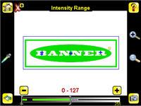
2. Click on the eye-dropper icon on the left of the screen, and then click anywhere in one of the white letters. Now any white area will be highlighted in green. Use the slider bar at the bottom of the display to fine tune the selection. As the slider bar is moved, green highlighted areas indicate objects the sensor finds and counts. The objects colored yellow are found, but filtered out (that is, not counted) because the objects fall outside of the Area Range.
• Adjust the Area Range. 1. Go to Main Menu > Inspection , and click the Area Range option.

2. Move the slider at the bottom of the screen to the to the desired area range. In the Demo example, the Area Range is adjusted so that each letter is identified as a found object (indicated by the green hightlights and the blue +).

• Set the Pass Count parameter. 1. Go to Main Menu > Inspection , and click the Pass Count option.
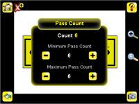
2. Set the Minimum Pass Count and Maximum Pass Count as appropriate. In the Demo, both are set to 6, since the inspection should find six letters. 6. Test the complete range of good and bad samples to make sure that the sensor accepts good parts and rejects bad. 7. To complete the Area application setup, set triggering as appropriate for your application.
NOTE: Remote Teach does not work with the Area Sensor type.
4.4 Configuring a Blemish Sensor
This section describes how to configure a Blemish sensor using the Demo application as a reference. The Demo application shows how the sensor, when configured as a Blemish tool, can accept or reject parts based on the range of edge pixels the sensor detects in the ROI. Start the setup with a good part. Normally, each part to be tested will be centered in the Field of View (FOV).
1. Adjust the Region of Interest (ROI).The ROI, when selected, is a red box as shown below.
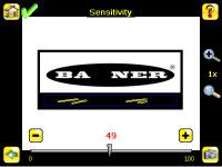
Resize the ROI so that the feature of interest. Resize the ROI so that it surrounds just the feature of interest. In the Blemish Demo example, the feature of interest includes the two irregular shapes below the Banner logo. 2. Click anywhere outside the ROI to deselect it. 3. Set inspection parameters. • Adjust the Sensitivity parameter. 1. Go to Main Menu > Inspection , and click the Sensitivity option.

2. Use the slider on the bottom of the screen to adjust the sensitivity watching as the sensor detects more or fewer edges. 3. Click the Trigger button on the bottom-right of the screen to see how the sensor detects edges on other images, and adjust if necessary.
• Adjust the Edge Length Range. 1. Go to Main Menu > Inspection , and click the Edge Length Range option.
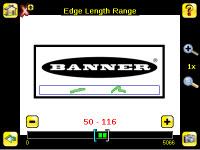
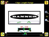
2. Move the slider at the bottom of the screen to the to the desired Edge Length Range. You can zoom in to refine the range.
• Set the Pass Count parameter. The sensor aggregates all the edge pixels that fall within the Edge Length Range and indicates the value with a small colored bar at the bottom of the page. If within the range brackets, the bar is green, otherwise it is yellow. 1. Go to Main Menu > Inspection , and click the Pass Count option.
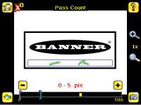
2. Use the brackets to set a tolerance for the pass/fail. 4. Test the complete range of good and bad samples to make sure that the sensor accepts good parts and rejects bad. 5. To complete the Blemish application setup, set triggering as appropriate for your application.
NOTE: Remote Teach does not work with the Blemish Sensor type.
4.5 Configuring a Match Sensor
This section describes how to configure a Match sensor using the Demo application as a reference
NOTE: By default, the Trigger is set to Internal, and will continously trigger based on a time interval setting. This may make it more difficult to make adjustments while setting up the sensor. The best practice is as follows: • Go to the Main Menu > Imager > Trigger menu and select External.
• Make sure there is no external trigger input. • Use the Trigger icon in the lower-right of the screen to manually trigger the sensor to capture an image as you set up and test. • Capture images of a range of samples to set up from the "worst" good part to the "best" bad part.
Start the setup with a good part. Normally, each part to be tested will be centered in the Field of View (FOV). 1. Teach the sensor a good reference part. a. Adjust the Region of Interest (ROI).The ROI is a blue-dotted box as shown below.
b. Click Anywhere within the ROI to select it. When selected, the ROI is red with resize and rotational icons in the corners.
c. Resize and move the ROI so that the feature of interest. Resize the ROI so that it surrounds just the feature of interest. In the
Demo example, the feature of interest is the Banner logo as shown below.


NOTE: When running a Match inspection, the sensor will look for any possible patterns to match anywhere within the Field of View. d. Click the Teach icon to teach the sensor this good reference part. With Annotations Enabled, the screen will highlight in green the pattern found.
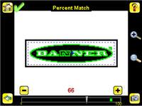
2. Set inspection parameters. • Adjust the Percent Match parameter.
NOTE: When running a Match inspection with annotations enabled, the sensor will hightlight in green any pattern matches that meet or exceed the value specified for Percent Match. Patterns that are below the specified value for Percent Match (down to approximately 20%), or out of the Rotation Range (see below), will be colored yellow
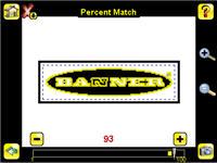
1. Using a "bad" part, click the Manual Trigger icon in the lower-right of the screen to capture an image. For this example, one of the stored images is missing the letter "N," yet the sensor initially sees this as a "good" label. 2. Go to Main Menu > Inspection , and click the Percent Match option.
3. On the adjustment at the bottom of the screen, adjust the slider and click the Manual Trigger button. When adjusted correctly, the annotations should turn yellow, and the icon in the upper-right of the screen shouid indicate fail.
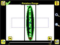
• Adjust the Rotation Range. Note that the smaller the rotation range, the faster the inspection will run. To set the Rotation
Range: 1. Go to Main Menu > Inspection , and click the Rotation Range option.
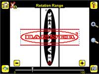
2. Move the slider at the bottom of the screen to the desired rotation. If you are verifying that a label is correctly applied to a container; that is, on straight, you will want to set a small rotation. If you want to make sure that the correct label is present no matter how the part is oriented in the Field of View, then the rotation range will be set to its maximum (180°, which is the setting for the Demo).
• Set the Pass Count parameter. 1. Go to Main Menu > Inspection , and click the Pass Count option.
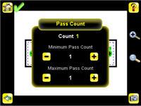
2. Set the Minimum Pass Count and Maximum Pass Count as appropriate. In the Demo, both are set to 1. 3. Test the complete range of good and bad samples to make sure that the sensor accepts good parts and rejects bad. 4. To complete the Match application setup, set triggering as appropriate for your application.
4.5.1 Remote Teach
The Remote Teach function is a method of remotely updating inspection parameters while the iVu sensor is running. Remote Teach is only available when the iVu is configured as a Match sensor. The sequence of events for executing a Remote Teach as follows: 1. With the sensor Ready, pulse the Remote Teach line. 2. The sensor recognizes that the Remote Teach line has been pulsed and waits for the next valid trigger. 3. At the next valid trigger, Ready goes inactive (the Green Ready LED shuts OFF), and the sensor acquires a new image. 4. The sensor learns the new pattern and performs the analysis.
4.6 Configuring a Sort Application
This section describes how to configure a Sort application using the Demo application as a reference
NOTE: By default, the Trigger is set to Internal, and will continously trigger based on a time interval setting. This may make it more difficult to make adjustments while setting up the sensor. The best practice is as follows: • Go to the Main Menu > Imager > Trigger menu and select External.
• Make sure there is no external trigger input. • Use the Trigger icon in the lower-right of the screen to manually trigger the sensor to capture an image as you set up and test. • Capture images of a range of samples to set up from the "worst" good part to the "best" bad part.
Start the setup with a good part. Normally, each part to be tested will be centered in the Field of View (FOV). 1. Make sure you use good parts for the inspection setup. Normally, each part will be centered in the field of view with the feature of interest surrounded by the Region of Interest (ROI), a blue rectangle. The ROI can be rotated and resized, and is red when selected for adjustment.
For the first part, select the ROI by clicking inside it. Move it, resize it, and rotate it by dragging the ROI or its corners. Once the feature of interest is within the ROI, click the Teach button. The feature will be highlighted in green.
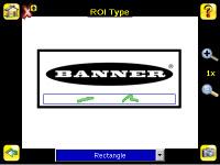
Tip: Use the short-cut menu in the upper-right of the screen to select an ROI-type. For better results, make sure that the ROI bounds the image of the pattern as tightly as possible.
NOTE: When running a Sort inspection, the sensor will look for any possible patterns to match anywhere within the field of view.
2. Click the Save button to save the pattern to the first empty pattern storage slot.
3. Set match criteria: • The Percent Match setting adjusts how closely the inspected part or label needs to match any of the ten stored patterns. The Percent Match scale is from 0 to 100, where 0 is the most tolerant and 100 is the least tolerant. Move the slider to the left or to the right to adjust the setting. For the best results, use a value from 50 to 90.
NOTE: When running a Sort inspection, the sensor will highlight in green any pattern matches that are within the specified Rotation Range and meet or exceed the value specified for Percent Match. Patterns that are within the specified Rotation Range and within approximately 20% below the specified value for Percent Match will be colored yellow. • The Rotation Range sets the expected rotation of parts or labels during an inspection. For example, a value of 45 means that the part may rotate 45 degrees in either direction from the reference part and still pass. Move the slider from 0 to 180 degrees. Note that the smaller the rotation range, the faster the inspection will run. 4. Repeat these steps for subsequent patterns and store each pattern in an empty pattern storage slot. 5. Set the Pass Criteria (assuming only two stored patterns): • Any Saved Pattern—Pass condition if the sensor matches either Pattern_1, Pattern_2, or both • All Saved Patterns—Pass condition if the sensor matches both Pattern_1 AND Pattern_2 • Single Saved Pattern—Pass condition if the sensor matches either Pattern_1 OR Pattern_2, but NOT both • Specific Save Pattern (Must also select the saved pattern to match, for example, select Pattern_2)—Pass condition any time the sensor matches Pattern_2
6.
Use the Manual Trigger, located in the lower-right corner of the screen, to test good and bad parts. Adjust settings as necessary and retest.

