LIST OF APPENDICES
AppendixA MechanicalPictures
AppendixB PlumbingPictures
AppendixC
AppendixD

1.0 INTRODUCTION
Crowne Plaza operates a 20-story hotel in downtown Syracuse. The original construction occurred in 1969 and was renovated in 2002. CHA was consulted to assist with a facilities assessment report by QPK Design.
Existing system plans from 1969 and 2002 were available for reference at time of this report. Information presented was gathered from an on-site investigation of the facility and the existing system plans. The report is to identify existing systems and identify current conditions. This report will also identify potential impacts of changing occupancy types from a hotel to apartments.
2.0 CONDITIONS ASSESSMENT
2.1 Mechanical
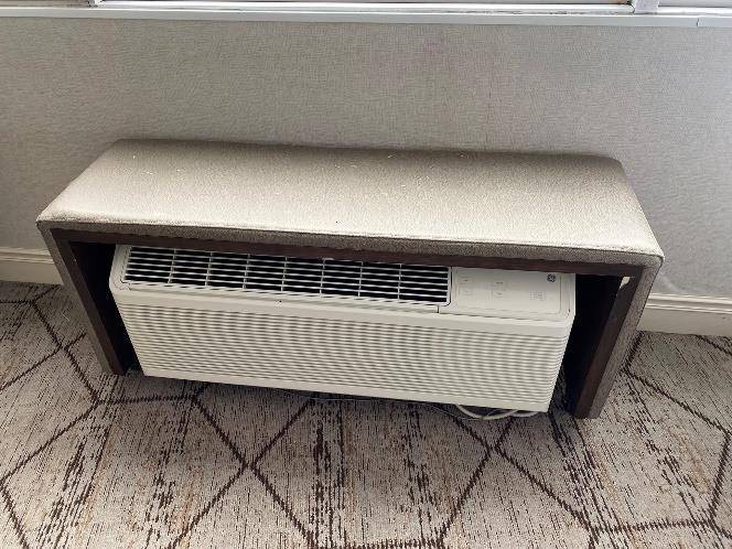
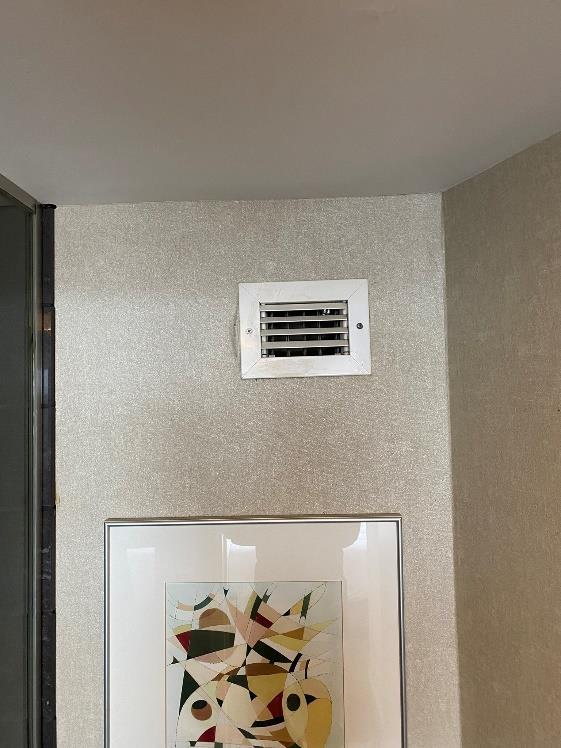
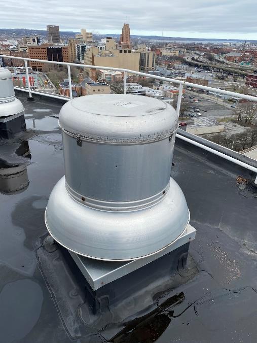
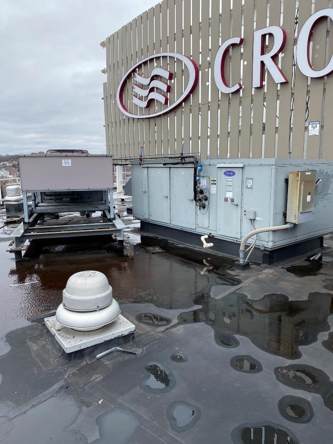
PTAC’s with electric heat were observed to be in every room under the windows to provide heating and cooling. These are one ton units and are from 2002. Each unit is connected to an individual thermostat on the wall that appears to be the same age as the unit Each typical room was also observed to have a 6”x4” exhaust grille on the wall above the toilet. Each grille is connected to an exhaust riser that runs up to the tower roof and terminates at a Carrier Corporation model 41K24 434 exhaust fan. This fan dates to before the 2002 upgrades. Seven air cooled packaged air conditioning rooftop units were observed on the tower roof. These units are Carrier model 50TM from 2002 and use R-22 refrigerant. They serve the 20th floor meeting rooms. Multiple exhaust fans are also located on the roof. Six of the fans serve as smoke exhaust for the meeting rooms, one is 20th floor smoke exhaust, and one is 20th floor kitchen/smoke exhaust. These are Loren Cook model 180C8B fans from 2002. There are two Mitsubishi MUY-GE18NA split systems on the tower roof that were noted on existing drawings as for the cable company Two new Daikin units on were observed on the lower roof that serve the restaurant. Additional rooftop units on the lower roof were observed to be from 2002. These units serve the lobby, health club, and general areas.
2.2
Plumbing
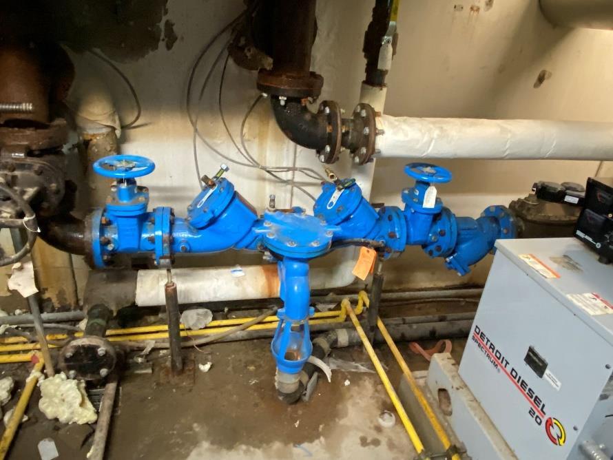
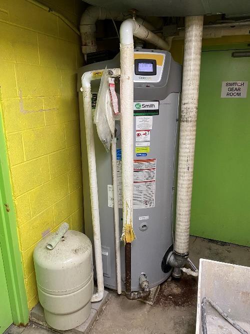
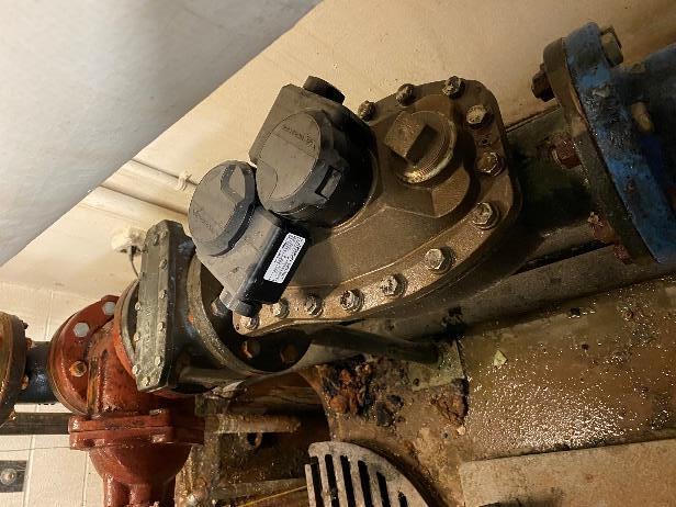
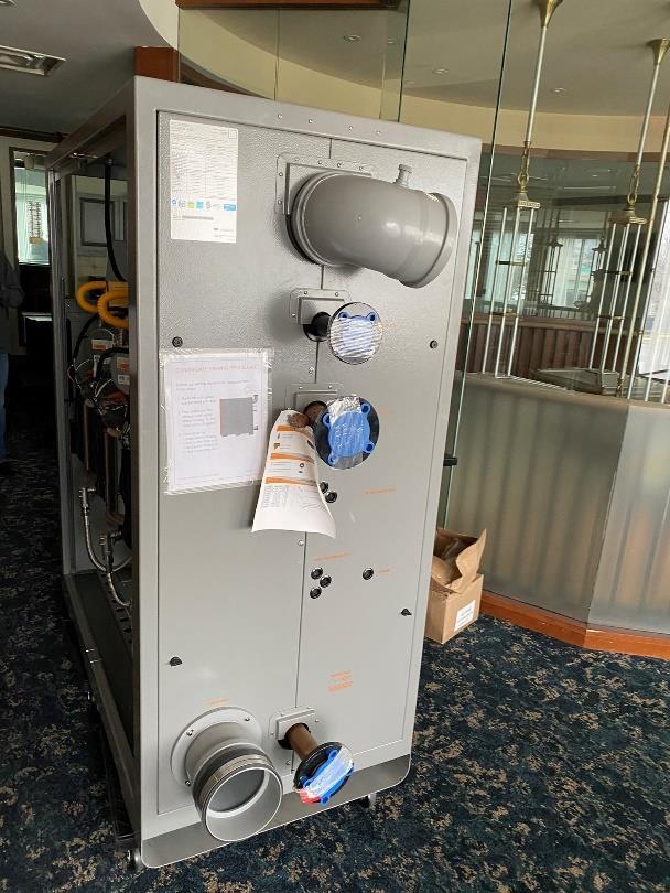
The building is served by a 4” water main. This water main enters the mechanical room where a water meter and 4” rpz are present. An A.O. Smith BH-500 119-gallon storage natural gas water heater with a build date of 3/21/2019 is located right outside the mechanical room. Next to it is an Amtrol ST-30V expansion tank sitting on two blocks off the ground. These units serve the four commercial washing machines located nearby in the basement. Piping serving the washers are run right behind each washer with sanitary piping running along the floor. The tank room in the basement consisted of a grease interceptor, large water heater and storage tanks. The water heater is a PLC Electric water heater model 100 LO from 1968 and appears to be abandoned There are 5 A.O. Smith T350S 350 gallon water storage tanks built in 2006. It appeared only two of the storage tanks are in operation as piping to the other three tanks are abandoned. Two new Intellihot 1,501,000 BTUH instantaneous water heaters were in the middle of being installed

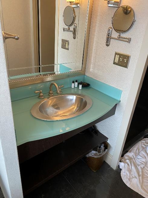
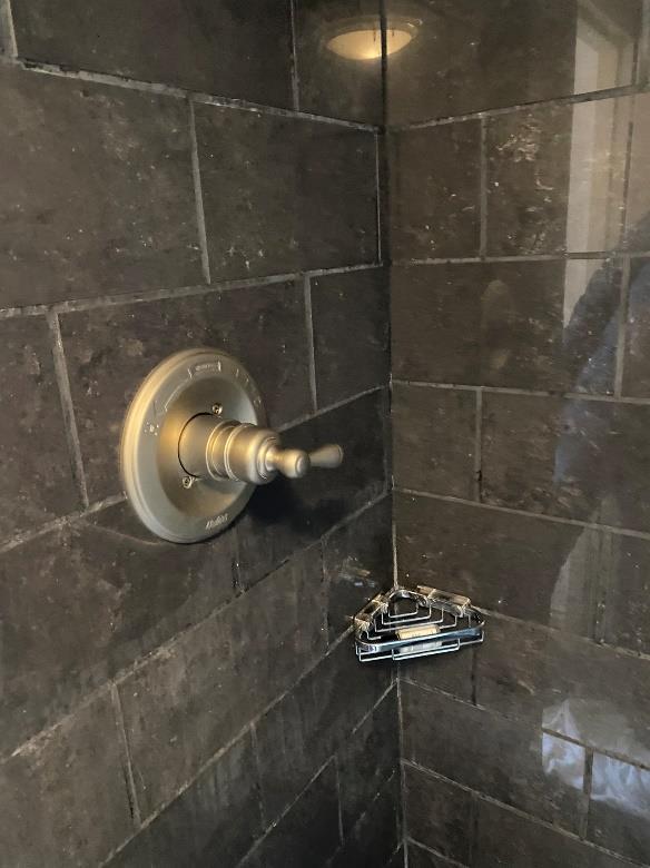
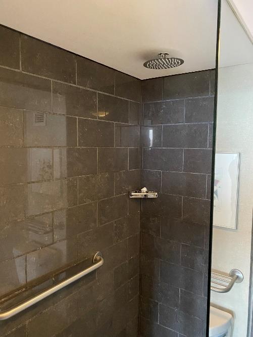
during the site visit. These are located on the 2nd floor mezzanine. New vents thru the roof were also being installed. These water heaters serve the guest rooms. Each typical room consisted of a shower, countertop mounted lavatory, and floor mounted flush tank type water closet. The plumbing serving these fixtures runs down a plumbing chase behind the water closet and shower.
2.3 Fire Protection
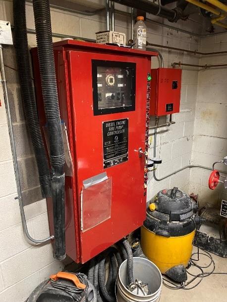
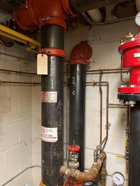
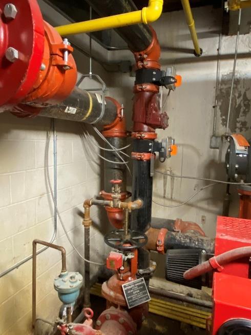
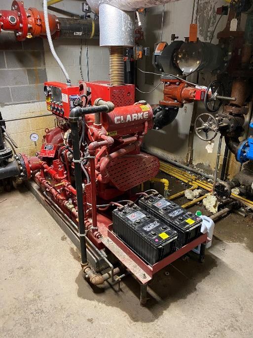
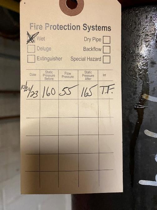
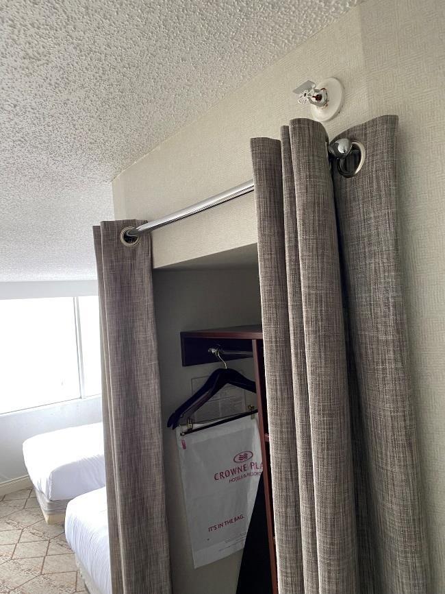
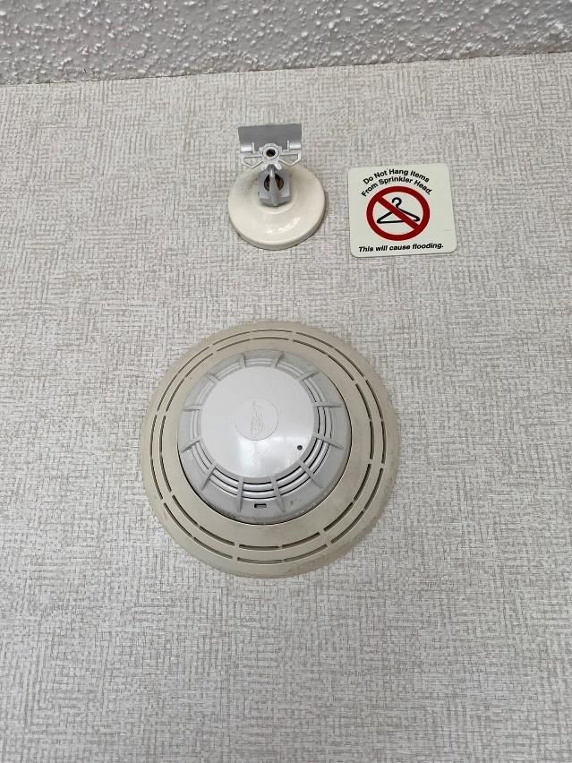
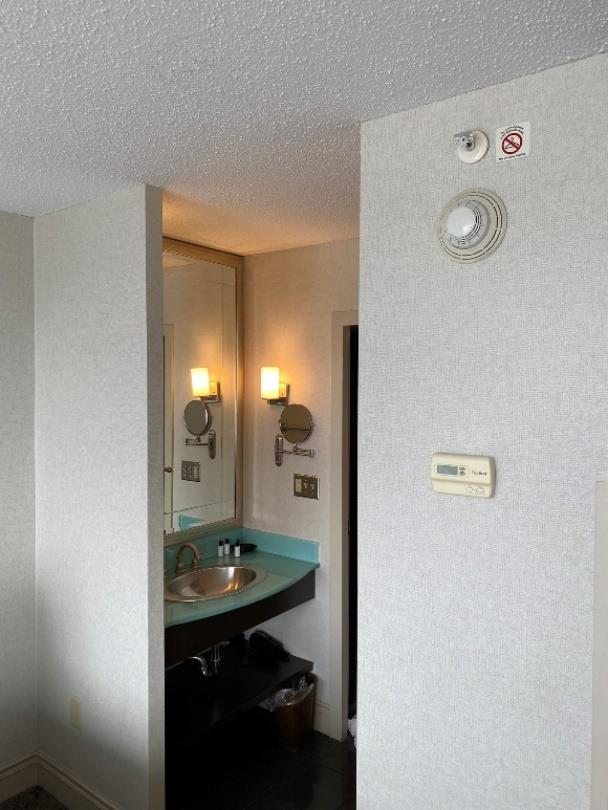
The building has a 6” fire service that enters in the fire pump room. There is also a 750-gpm fire pump, 10-gpm jockey pump, and fire pump controller. These items appear to be from 2002. It is a wet fire protection system. There is a 6” standpipe and 6” sprinkler riser that runs up through the building. A 3” main splits off at each floor and runs through the corridor. A 1 ¼” branch pipe serves each room. Each room was observed to have two sprinkler heads. One head is located on the wall above the closet and one on the wall adjacent to the bathroom and above a smoke detector.
2.4 Electrical
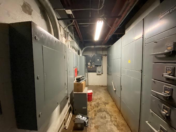
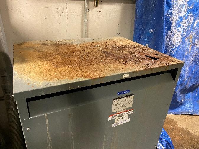
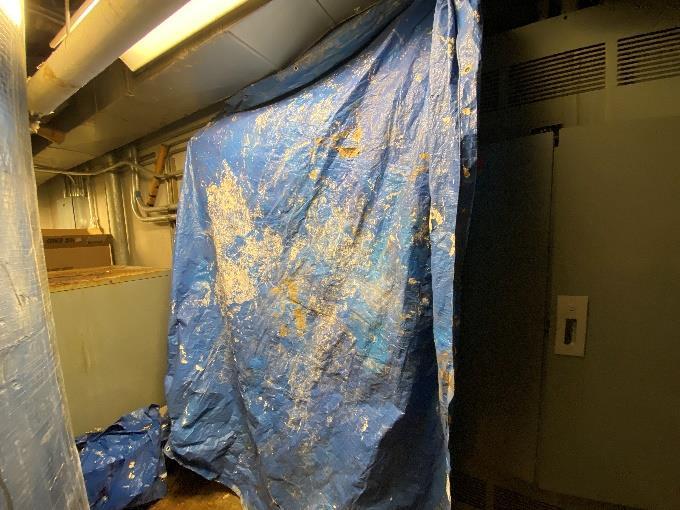
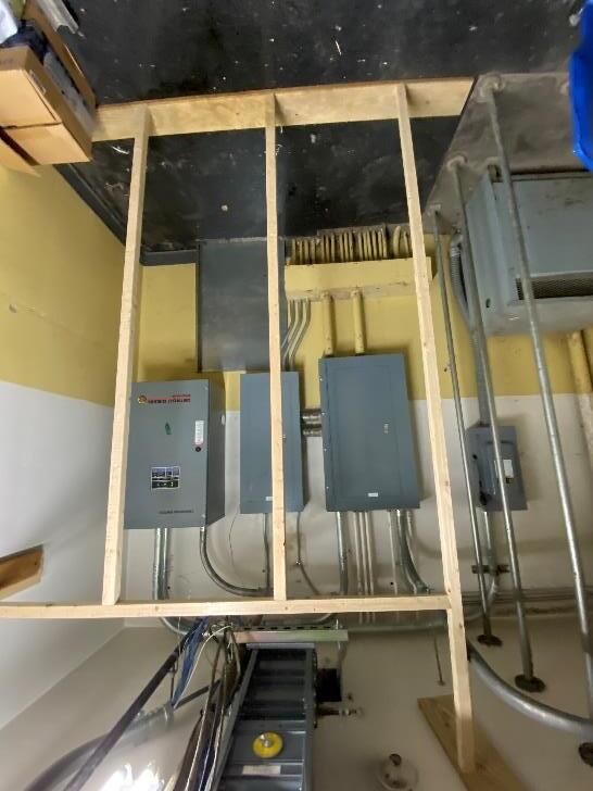
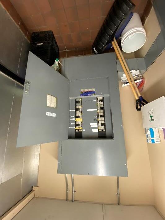
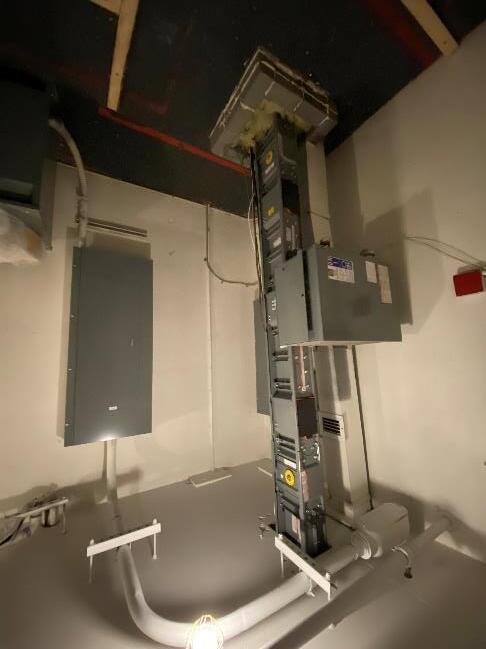
The existing electrical service consists of a 2500A 480/277V Square D Bolt-Loc main switchboard located in the basement, it appears to be original to the 1969 construction. There are various fused switches that feed branch distribution panels throughout the facility as well as a 1600A switch that feeds a 480/277V 1600A bus duct that that runs from the basement up to the penthouse. The busduct has a 200A plug connected to it on each floor in the electrical closet that feeds a 480/277V panel. During the 2002 renovation additional panels were connected to the main service. There are currently three separate electrical meters in the main electrical room, one meters the general building, one meters a motor control center in the penthouse and one meters panel TP-1. The arrangement of the current electrical room does not meet national electrical code (NEC), per the latest version of the NEC the electrical room would require two exits. Transformer T1 resides in the water tank room in the basement, there is a water leak above the transformer which has dripped water on the top of transformer and caused a large rust hole. Adjacent to the transformer is a 600A 120/208V panel and a 50A 120/208V panel that have plastic tarp draped over them to divert water away from the panels from another leaking water pipe.
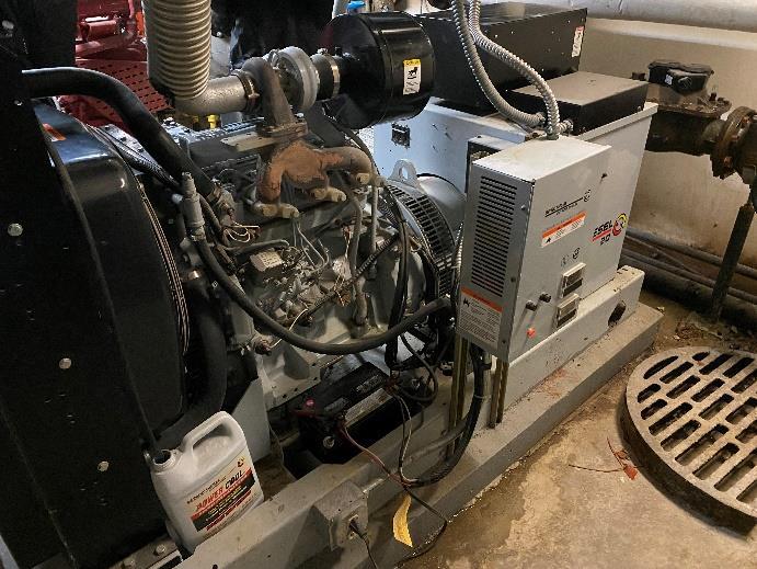
There is a 30kva Detroit Diesel 120/208V diesel fired generator located in the basement which appears to be from the 2002 renovation. The generator provides emergency power to emergency egress and stairway lights throughout the building. The generator appears to be operational but is likely nearing the end of its life and should be considered for replacement. Lighting through the facility consists of various types of lights from incandescent to fluorescent to newer energy efficient LED’s. In general, the light levels thorough out the facility are appropriate, specifically the egress paths appear to have the required light levels. Exit signs are located throughout the building where they are required.
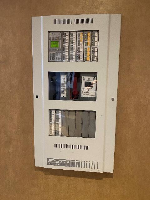
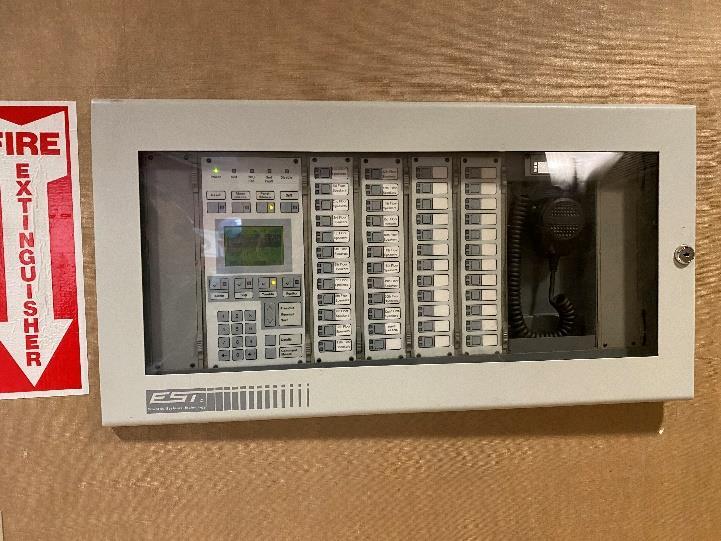
The fire alarm system consists of a fire alarm control panel located near the lobby, with a remote annunciator located in the reception area. Initiating and annunciating devices were located where required. The fire alarm system is an Edwards EST3 system, this system is obsolete and no longer supported by Edwards, finding replacement parts when repairs are needed will be difficult.

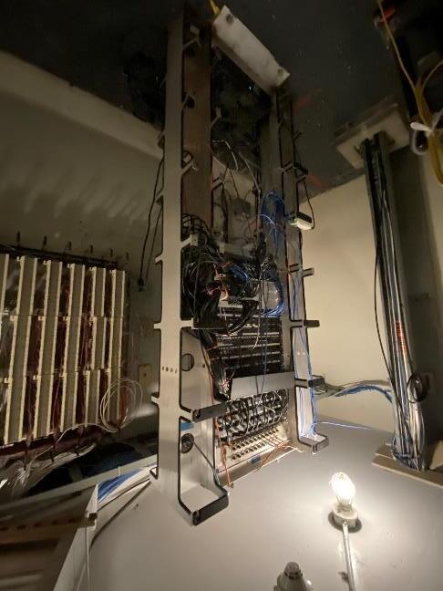
The main telecommunications rack is located on the 19th floor in the electrical closet. It consists of telephone punchdown blocks mounted on the wall as well as a free standing two post data racks that contains fiber optic patch panels as well as cat6 network switches. From the 19th floor data is distributed throughout the building.
3.0 RECOMMENDATIONS & IMPACTS
3.1
Mechanical
Multiple mechanical units are nearing their end of life expectancy. A typical PTAC life expectancy is 15 years. The typical room PTAC with electric heat is over 20 years old are recommended to be replaced with newer more efficient units along with newer thermostats The life expectancy of the rooftop units is about 20 years. Due to the age and use of R-22 refrigerant, which is no longer available, it is recommended to replace these units. The exhaust fan life expectancy is 20-25 years. It is recommended to look farther into exhaust fan conditions as maintenance may increase this life span.
Occupancy changes may impact the mechanical systems. Ventilation requirements may require mechanical means of ventilation due to occupancy types. Review of existing smoke control system and design required to ensure renovation level does not require updating existing system design or capacity New dwelling units with kitchen equipment would require additional exhaust and an update to current building exhaust systems
3.2
Plumbing
The water heater serving the washing machines and the newly installed instantaneous water heaters are in good shape and should be adequate for renovations. It is recommended looking into options for the abandoned equipment in the tank room, if no longer needed then they should be removed and space freed up for additional facility use. Plumbing fixtures within each room are in good shape and not needing replacement, but if programming facilities fixture replacement our recommendation is using higher efficiency fixtures.
Occupancy changes should have minor impacts on plumbing. If fixture counts remain the same, the demand would remain the same, and no impact on existing water or drainage risers. The water demand would need to be evaluated if additional fixtures such as a kitchen sink or domestic washing machines are added into each room.
3.3
Fire Protection
The age of both fire pumps is nearing the end of effective life. Confirmation of any additional maintenance on these pumps will be needed to justify not replacing these pumps during the renovation Sprinkler piping and heads should not need to be updated unless architectural changes to the rooms require changes in sprinkler coverage or pipe routing
The fire service and sprinkler coverage in the individual rooms shall be adequate for occupancy change. Sprinkler head locations will need to be evaluated for any new obstructions or layout changes to the room are made.

3.4 Electrical
In general the power distribution system is functional, the main switchboard in the basement should be considered for replacement as it is well past it’s useful life. Replacement of the switchboard will be difficult as there is no easy access to the electrical room for removal of equipment or installation of new equipment. In addition the current electrical room does not meet current code, a second means of egress would need to be installed into the electrical room and that may not be possible. If electric cooking appliances are installed in the apartments the existing electrical service will be undersized and will need to be upgraded. A new electrical room will need to be created that has access to get the new gear into the building. If the new apartments are intended have their electricity metered separately all the apartments would need to be rewired as they currently share circuits between them. The transformer with the rust hole in the water tank room in the basement must be replaced and the water leak above it repaired. The water leak in the water tank room in the basement that is over the top of two power panels must be fixed. The existing lighting can continue to be used, new light fixtures would be installed in any area where ceiling renovations are made. The fire alarm panel should be replaced with a current offering from Edwards so that parts are available when repairs are needed.

4.0 REFERENCES
Holiday Inn 1967 Drawing set
The Marx Hotel & Conference Center Drawings from 2002
ASHRAE Equipment Life Expectancy Chart
2020 New York State Building Codes


