
TABLE OF CONTENTS
// MASTER PLAN STUDY May, 2023 FINAL Table of Contents i
1 Water and Sanitary Sewer Assessment................................................................................ 1-1 1.1 Summary...................................................................................................................... 1-1 1.1.1 Water Mains ....................................... .................. 1-1 1.1.2 Sanitary Sewer Gravity Mains.................................................................................. 1-2 1.1.3 Force Mains.............................................................................................................. 1-2 1.1.4 Pump Stations.......................................................................................................... 1-2 1.2 Inspections....................................... ......................... 1-3 1.3 Recommendations....................................................................................................... 1-4 1.3.1 Water Mains ............................................................................................................ 1-4 1.3.2 Sanitary Sewer Gravity Mains...................... ......... 1-4 1.3.3 Force Mains....................................... .................... 1-5 1.3.4 Pump Stations.......................................................................................................... 1-5 2 Architectural Assessment (ARCH)........................................................................................ 2-1 2.1 Building 1 (Terminal Building).................... ............... 2-1 2.1.1 Summary.................................................................................................................. 2-1 2.1.2 Elevators................................................................................................................... 2-1 2.1.3 Inspection Notes ...................................................................................................... 2-1 2.1.4 Recommendations................................... ............. 2-2 2.1.5 Automatic Motorized Sliding Doors......................................................................... 2-2 2.1.6 Inspection Notes ...................................................................................................... 2-2 2.1.7 Recommendations................................................................................................... 2-3
Roof Assemblies....................................................................................................... 2-4 2.1.9 Inspection Notes ...................................................................................................... 2-5 2.1.10 Recommendations.................................................................................................2-10 2.1.11 Motorized Hangar Doors ............................ ........2-10 2.2 Building 13 (Museum)................................................................................................2-11 2.2.1 Summary................................................................................................................2-11 2.2.2 Motorized Doors....................................................................................................2-11 2.2.3 Inspection Notes .................................. ...............2-11
2.1.8

// MASTER PLAN STUDY May, 2023 FINAL Table of Contents ii 2.2.4 Recommendations.................................................................................................2-11 2.3 Building 15 (Hangar 15) .............................................................................................2-12 2.3.1 Summary........................................... ..................2-12 2.3.2 Motorized Doors....................................................................................................2-12
Inspection Notes ....................................................................................................2-13 2.3.4 Recommendations................................... ...........2-14 2.4 Building 16 (Hangar 16) ........................... ...............2-14 2.4.1 Summary................................................................................................................2-14 2.4.2 Motorized Doors....................................................................................................2-14 2.4.3 Inspection Notes .................................. ...............2-14 2.4.4 Recommendations.................................................................................................2-15 2.5 Building 19 (Hangar 19) .............................................................................................2-15
Summary................................................................................................................2-15
Motorized Doors................................... ..............2-15 2.5.3 Inspection Notes ....................................................................................................2-16 2.5.4 Recommendations.................................................................................................2-16 2.6 Building 25 .................................................................................................................2-17 2.6.1 Summary................................................................................................................2-17 2.6.2 Motorized Doors....................................................................................................2-17 2.6.3 Inspection Notes ....................................................................................................2-17 2.6.4 Recommendations................................... ...........2-18
Building 26 .................................................................................................................2-18
Summary................................................................................................................2-18 2.7.2 Motorized Doors....................................................................................................2-18 2.7.3 Inspection Notes .................................. ...............2-18 2.7.4 Recommendations.................................................................................................2-19 2.8 Building 27 .................................................................................................................2-19 2.8.1 Summary........................................... ..................2-19 2.8.2 Motorized Doors................................... ..............2-19
Inspection Notes ....................................................................................................2-19
Recommendations.................................................................................................2-20
2.3.3
2.5.1
2.5.2
2.7
2.7.1
2.8.3
2.8.4

// MASTER PLAN STUDY May, 2023 FINAL Table of Contents iii 2.9 Building 28 .................................................................................................................2-20 2.9.1 Summary................................................................................................................2-20 2.9.2 Motorized Doors................................... ..............2-20 2.9.3 Inspection Notes ....................................................................................................2-20 2.9.4 Recommendations.................................................................................................2-21 2.10 Building 29 ....................................... .......................2-21 2.10.1 Summary........................................... ..................2-21 2.10.2 Motorized Doors....................................................................................................2-21 2.10.3 Inspection Notes ....................................................................................................2-21 2.10.4 Recommendations................................... ...........2-22 2.11 Building 45 .................................................................................................................2-22 2.11.1 Summary................................................................................................................2-22 2.11.2 Motorized Doors....................................................................................................2-22 2.11.3 Inspection Notes .................................. ...............2-22 2.11.4 Recommendations.................................................................................................2-24 2.12 Building 51 .................................................................................................................2-24 2.12.1 Summary................................................................................................................2-24 2.12.2 Motorized Doors....................................................................................................2-24 2.12.3 Inspection Notes ....................................................................................................2-24 2.12.4 Recommendations.................................................................................................2-28 2.13 Building 57 ....................................... .......................2-28 2.13.1 Summary................................................................................................................2-28 2.13.2 Motorized Doors....................................................................................................2-28
Inspection Notes ....................................................................................................2-28 2.13.4 Recommendations................................... ...........2-29 2.14 Building 106 (4480 Gumbert Road) ...........................................................................2-29 2.14.1 Summary................................................................................................................2-29 2.14.2 Motorized Doors................................... ..............2-29 2.14.3 Inspection Notes .................................. ...............2-30 2.14.4 Recommendations.................................................................................................2-33 2.15 Building 107 (4476 Gumbert Road) ...........................................................................2-33
2.13.3

// MASTER PLAN STUDY May, 2023 FINAL Table of Contents iv 2.15.1 Summary................................................................................................................2-33 2.15.2 Motorized Doors....................................................................................................2-33 2.15.3 Inspection Notes .................................. ...............2-33 2.15.4 Recommendations.................................................................................................2-34 2.16 Building 108 (4472 Gumbert Road) ...........................................................................2-34 2.16.1 Summary........................................... ..................2-34 2.16.2 Motorized Doors................................... ..............2-35 2.16.3 Inspection Notes ....................................................................................................2-35 2.16.4 Recommendations.................................................................................................2-37 2.17 Building 109 (4464 Gumbert Road) .................. ......2-37 2.17.1 Summary................................................................................................................2-37 2.17.2 Motorized Doors....................................................................................................2-37 2.17.3 Inspection Notes ....................................................................................................2-37 2.17.4 Recommendations................................... ...........2-39 2.18 Building 70 (ARFF Training Center)............................................................................2-39 2.18.1 Summary................................................................................................................2-39 2.18.2 Roof Assembly........................................................................................................2-39 2.18.3 Inspection Notes ....................................................................................................2-39 2.18.4 Recommendations.................................................................................................2-43 3 Mechanical Assessment (HVAC).......................................................................................... 3-1 3.1 Building 1 (Terminal Building).................... ............... 3-1 3.1.1 Summary.................................................................................................................. 3-1 3.1.2 Inspection Notes ...................................................................................................... 3-3 3.1.3 Recommendations................................................................................................... 3-3 3.2 Building 4 (Radio Support)........................ ................ 3-4 3.2.1 Summary.................................................................................................................. 3-4 3.2.2 Inspections............................................................................................................... 3-4 3.2.3 Recommendations................................... ............. 3-5 3.3 Building 6 (Freight & Maintenance bldg)........... ....... 3-6 3.3.1 Summary.................................................................................................................. 3-6
Inspections............................................................................................................... 3-7
3.3.2

// MASTER PLAN STUDY May, 2023 FINAL Table of Contents v 3.3.3 Recommendations................................................................................................... 3-7 3.4 Building 13 (Museum).................................................................................................. 3-8 3.4.1 Summary........................................... .................... 3-8 3.4.2 Inspections............................................................................................................... 3-8 3.4.3 Recommendations................................................................................................... 3-9 3.5 Building 45 (Hangar 45) ........................... ................. 3-9 3.5.1 Summary........................................... .................... 3-9 3.6 Building 50 (Electrical Vault)......................................................................................3-10 3.6.1 Summary................................................................................................................3-10 3.6.2 Inspections....................................... ...................3-10 3.6.3 Recommendations.................................................................................................3-10 3.7 Building 51 (Maintenance Bldg).................................................................................3-11
Summary................................................................................................................3-11 3.7.2 Inspections....................................... ...................3-11 3.7.3 Recommendations.................................................................................................3-13 3.8 Building 70 (ARFF Training Center)............................................................................3-13 3.8.1 Summary................................................................................................................3-13 3.8.2 Inspections.............................................................................................................3-13 3.8.3 Recommendations.................................................................................................3-15 3.9 Building 109 (WESTLEX).............................................................................................3-15 3.9.1 Summary........................................... ..................3-15
Inspections.............................................................................................................3-15 3.9.3 Recommendations.................................................................................................3-16 4 Building Plumbing Assessment............................................................................................. 4-1 4.1 Building 1 (Terminal Building).................... ............... 4-1 4.1.1 Summary.................................................................................................................. 4-1 4.1.2 Inspections............................................................................................................... 4-1 4.1.3 Recommendations................................... ............. 4-4 4.2 Building 51 (Maintenance Building)................ .......... 4-5 4.2.1 Summary.................................................................................................................. 4-5
Inspections............................................................................................................... 4-5
3.7.1
3.9.2
4.2.2

// MASTER PLAN STUDY May, 2023 FINAL Table of Contents vi 4.2.3 Recommendations................................................................................................... 4-7 4.3 Building 57 (ARFF)........................................................................................................ 4-7 4.3.1 Summary........................................... .................... 4-7 4.3.2 Inspections............................................................................................................... 4-7 4.3.3 Recommendations................................................................................................... 4-9 5 Fire Protection Assessment........................ ....................... 5-1 5.1 Building 1 (Terminal Building).................... ............... 5-1 5.1.1 Summary.................................................................................................................. 5-1 5.1.2 Inspections & Recommendations............................................................................ 5-3 5.2 Building 51 (Maintenance Bldg).................... ............ 5-3 5.2.1 Summary.................................................................................................................. 5-3 5.2.2 Inspections & Recommendations............................................................................ 5-4 5.3 Building 57 (ARFF)........................................................................................................ 5-4
Summary........................................... .................... 5-4 5.3.2 Inspections & Recommendations............................................................................ 5-5 6 Electrical Assessment ........................................................................................................... 6-1 6.1 Building 1 (Terminal Building)...................................................................................... 6-1 6.1.1 Summary.................................................................................................................. 6-1 6.1.2 Inspection Notes ...................................................................................................... 6-2 6.1.3 Recommendations................................................................................................... 6-8 6.2 Building 2 (Parking Garage)........................ ............... 6-8
Summary.................................................................................................................. 6-8 6.2.2 Inspections............................................................................................................... 6-9 6.2.3 Recommendations.................................................................................................6-10 6.3 Building 4 (Radio Support)........................ ..............6-10 6.3.1 Summary................................................................................................................6-10 6.3.2 Inspections.............................................................................................................6-11 6.3.3 Recommendations................................... ...........6-12 6.4 Building 5 (Rental Car Facility) .................. ..............6-12 6.4.1 Summary................................................................................................................6-12
Inspections.............................................................................................................6-12
5.3.1
6.2.1
6.4.2

// MASTER PLAN STUDY May, 2023 FINAL Table of Contents vii 6.4.3 Recommendations.................................................................................................6-13 6.5 Building 13 (Museum)................................................................................................6-13 6.5.1 Summary........................................... ..................6-13 6.5.2 Inspections.............................................................................................................6-13 6.5.3 Recommendations.................................................................................................6-14 6.6 Building 15 (Hangar 15) ........................... ...............6-14 6.6.1 Summary........................................... ..................6-14 6.6.2 Inspections.............................................................................................................6-15 6.6.3 Recommendations.................................................................................................6-16 6.7 Building 16 (Hangar 16) ........................... ...............6-16 6.7.1 Summary................................................................................................................6-16 6.7.2 Inspections.............................................................................................................6-17
Recommendations.................................................................................................6-17
Building 45 (Hangar 45) ........................... ...............6-18 6.8.1 Summary................................................................................................................6-18 6.8.2 Inspections.............................................................................................................6-18 6.8.3 Recommendations.................................................................................................6-19 6.9 Building 50 (Electrical Vault)......................................................................................6-19 6.9.1 Summary................................................................................................................6-19 6.9.2 Inspections.............................................................................................................6-19
Recommendations................................... ...........6-21
Building 51 (Maintenance Bldg).................................................................................6-21 6.10.1 Summary................................................................................................................6-21 6.10.2 Inspections.............................................................................................................6-22 6.10.3 Recommendations................................... ...........6-22 6.11 Building 57 (ARFF)......................................................................................................6-22 6.11.1 Inspections.............................................................................................................6-23 6.11.2 Recommendations................................... ...........6-23
Building 70 (ARFF Training Center)................ .........6-23
Inspections.............................................................................................................6-23
Recommendations.................................................................................................6-25
6.7.3
6.8
6.9.3
6.10
6.12
6.12.1
6.12.2

// MASTER PLAN STUDY May, 2023 FINAL Table of Contents viii 6.13 Building 109 (WESTLEX).............................................................................................6-25 6.13.1 Inspections.............................................................................................................6-26 6.13.2 Recommendations................................... ...........6-26 Appendix A (Buildings Map)............................................................................................................ 1 Appendix B (Terminal Roof Map).................................................................................................... 2 Appendix C (ASHRAE Equipment Life Expectancy Chart) ............. 3

1 WATER AND SANITARY SEWER ASSESSMENT
CHA Consulting, Inc. (CHA) was tasked with assessing the current conditions of the major components on the Water Supply and Sanitary Sewer Systems to identify areas of concern and make recommendations for repairs or replacement based on those assessments, prioritizing those with worsened conditions ratings. After discussing the scope of work with Blue Grass Airport (BGA, LEX, or the Airport) personnel, major infrastructure components were identified within the water mains, sewer mains, force mains, and pump stations. The water supply mains are those larger diameter pipes which are on the exterior of the buildings and buried underground that help carry the water to the building facilities. The sewer mains were defined as the sections of pipe between manholes on the exterior of buildings. These are not to be confused with building plumbing which is the water and drainage infrastructure on the interior of the building. Force mains are the pressure pipes that carry sanitary waste from a pump station to a discharge point either in a manhole or some other point in the gravity sewer system.
On July 13th, 2022, representatives of CHA met with BGA staff to discuss and better understand their understanding of these assets. Based off these discussions, CHA created inspection forms that would be used to look at a list of items for each asset type before determining the assets condition. Only visual assessments were to be performed and performance testing was not within this scope of work. There is no closed-circuit television (CCTV) footage or previous leak testing data available for any of the water or sanitary sewer lines within this study, so condition assessments were to be based upon the age of service and remaining life expectancy of the assets.
1.1 SUMMARY
1.1.1 Water Mains
There are 20,355 feet of BGA owned water main line ranging from one-inch up to twelve-inches in diameter with most of the main line being between two-, six-, eight-, and ten-inches in diameter. Of that, roughly half of all BGA owned water main line is eight-inch diameter pipe. Roughly half of the water mains are either Polyvinyl Chloride (PVC) or Ductile Iron pipe. The other half is unknown at the time of this report. PVC pipe is essentially plastic pipe while Ductile Iron pipe is comprised of steel. Iron pipe has been used for many years for water mains and still continues to be used. Though PVC has a shorter history being used as water mains, it has become quite popular the last couple decades. The benefits to going with PVC is the cheap cost to produce and corrosion resistant nature. Ductile Iron pipe is prone to corrosion and costlier to produce as the cost of steel is much higher than plastic.
The oldest sections of pipe were installed in 1974 while the newest sections of pipe have been installed as recently as 2018. Refer to Figure-1-1-1 for a map of the active airport owned water mains.
// MASTER PLAN STUDY May, 2023 FINAL Water and Sanitary Sewer Assessment 1-1

1.1.2 Sanitary Sewer Gravity Mains
There are 14,617 feet of active BGA owned sanitary sewer main ranging from four-inch diameter up to twelve-inch diameter pipe. Roughly three-quarters (75%) of sanitary sewers within the system is eight-inch diameter in size. According to airport records, one hundred percent (100%) of the sanitary sewer main line material is PVC.
Much like the water main, the oldest known section of gravity main was installed in 1974. The newest sections were installed in 2017. Please refer to Figure-1-1-3 for a map of the active Sanitary Sewer Gravity Mains.
1.1.3 Force Mains
There are 14,800 feet of active sanitary sewer force main ranging in size from one-inch to eightinch in diameter. Around seventy-one percent (71%) of the force mains are comprised of one and a half-inch, two-inch, and three-inch diameter mains. Half of the force main material is unknown, and the remaining is split between PVC and High Density Polyethylene (HDPE). PVC is a vinyl based plastic product while HDPE is a polyethylene thermoplastic made from petroleum. While both are light weight and corrosion resistant. PVC is typically used in open cut excavation installations and HDPE is widely used as a trenchless install option.
The oldest active force main was installed in 1980. The newest fore main was put into service in 2020. Please refer to Figure-1-1-4 for a map of the active BGA Sanitary Force Main.
1.1.4 Pump Stations
There are ten pump stations around the airport that BGA owns. These are typically duplex stations but there is at least one simplex station used for condensate runoff and floor drains in the lower level of Boiler Room 2. Please refer to the 2022 pump station condition assessments included with this report for a complete list of inspections.
Table 1-1-1 – Pump Station Asset Register
Pump Station-1-3
Lower level of Boiler Room 2 in the corner by stairwell
Pump station for boiler 2 floor drains 1989
Pump Station-0-4 Managers Lot Managers lot pump station 2004
Pump Station-109-1
Pump Station-51-1
West side of road to the west of WestLEX general aviation building. WestLEX pump station 2009
Southeast side of SRE/Maintenance buildings in the grass.
Pump Station for Maintenance building. 2014
// MASTER PLAN STUDY May, 2023 FINAL Water and Sanitary Sewer Assessment 1-2
Asset Name Location Description Description Install Year

Pump Station-47-1
Pump Station-0-3
South side of building next to chain link fence
Pump Station around retention ponds by taxi way Charlie
Pump Station-1-2 Boiler Room 3
Pump Station-0-1
Pump Station for Building 47. N/A
Pump Station around retention ponds by taxi way Charlie 2020
Pump Station for Concourse B 2006
Parking Attendant/Exit Gates Parking Attendant/Exit pump station for restroom. N/A
Pump Station-2-1 Northeast side of Parking Garage Parking Garage Pump Station N/A
Pump Station-1-1 Concourse B
Grinder Pump Station for Concourse B 2021
Note:N/Aindicatedinformationnotavailableofunabletoverifyinfield.
1.2 INSPECTIONS
Any asset class's expected useful life fluctuates widely depending on the expected use, make, model, material, installation, maintenance practices, etc. CHA chose to use Environmental Protection Agency (EPA) publications to determine the estimated equipment life expectancies for those underground assets requiring the desktop condition assessments. The expected useful life for water mains and force mains is forty (40) years while the sanitary sewer gravity mains expected useful life is one hundred (100) years. To determine the condition, we used a rating system of 1-5, where one (1) is the best and five (5) is the worst. For the underground assets, condition was based on asset age. The assumed install date for each asset was based on existing geographic information system (GIS) data and discussions with BGA Staff. We then determined age based on the install date and calculated the remainder of the useful life consumed. Based on these percentages, we determined the following condition ratings according to percent of the assets useful life expectancy consumed:
1. One (1) rating 0-20;
2. Two (2) rating 21-40;
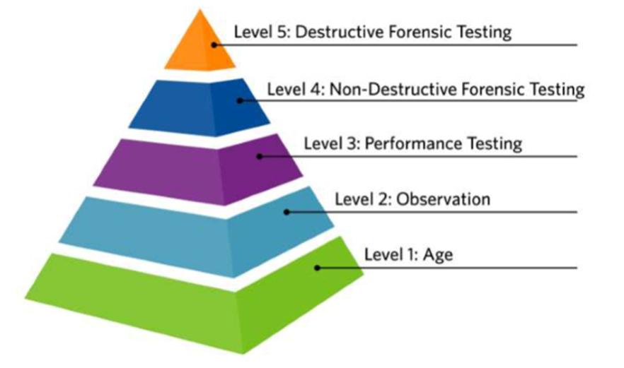
Figure 1: The Confidence Hierarchy shows that age and material can be used to estimate remaining useful life. It is the easiest desktop analysis to get Blue Grass Airport started.
// MASTER PLAN STUDY May, 2023 FINAL Water and Sanitary Sewer Assessment 1-3 Asset Name Location Description Description Install Year

3. Three (3) rating 41-60; 4. Four (4) rating 61-80; 5. Five (5) rating 81-100+.
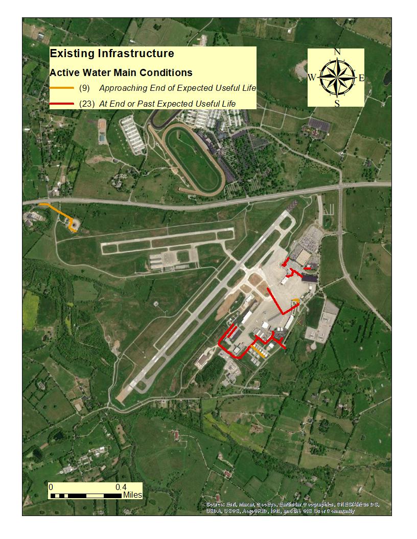
Please note that only the sections of underground infrastructure rating a 4 or 5 are recommended for review/repair/replacement. Anything that rated 1 through 3 are considered to be in satisfactory condition based on their percentage of consumed life expectancies alone. Please refer to Figure-1-1-2 for a map of those water mains rating either a 4 or 5. Likewise, Figure-1-1-5 for a map of those force mains rating either a 4 or 5. In these two maps, sections that rated a 4 will be classified as “Approaching end of expected useful life” and those sections rated as 5 will be shown as “At end or past expected useful life”. Using the Sanitary Pump Station Condition Assessment Inspection form along with the assessor’s experience and when available, BGA staff input, we were able to give condition ratings for each of the pump stations. CHA noted that the staff at BGA does not maintain the pump stations but rather contracts those services out. There were a couple of pump stations that were unable to be visually inspected as they had bolt down lids and BGA staff determined it was not necessary to remove for inspection. In these instances, the condition ratings were rated as a three (3) unless other above ground issues were found in which case the rating may be higher.
1.3 RECOMMENDATIONS
1.3.1
Water Mains
Based on the desktop assessment which defined the percentage of useful life consumed for each section, start planning for repair/replacement of the water mains that are at, near, or over their expected useful lives. There are 32 sections of pipe that fall into the Level Four or Five (4/5) condition rating categories with a total footage of 9,608 feet. Most of this is 8-inch diameter pipe that was installed between 1980 and 1996.
It is recommended to take a more in depth look at historical data sheets (where available) to assess the number of breaks/issues per section of line and to perform leak tests on all water mains to better evaluate pipe conditions and to make recommendations for repair/replacement based on those findings.
1.3.2
Sanitary Sewer Gravity Mains
Based on the desktop assessment, it was determined that the gravity mains are in good (3) condition according to their age and materials listed in GIS. No section of main rates higher than a Level Three (3) on the scale. Many of the sections scoring a Level Three (3) are 8-inch in diameter and were installed between 1974 and 1980. It is recommended to clean and televise all sanitary main lines to better evaluate the internal conditions and to spot any Infiltration plus defects that could result in a possible back up or pipe failure.
// MASTER PLAN STUDY May, 2023 FINAL Water and Sanitary Sewer Assessment 1-4

1.3.3
Force Mains
Based on the desktop assessment, start planning for repair/replacement of the force mains that are at, near, or over their expected useful lives. There is one section of force main that falls into the Level Five (5) condition rating category with a total footage of 2,057 feet. This section is 3inch in diameter and was installed in 1980.
It is recommended to take a more in depth look at historical data sheets (where available) to assess the number of breaks/issues per section of line to compare with the desktop assessment. It is also recommended to get the force mains on a rotating cleaning schedule. To clean a force main, you run a device called a “pig” through the line that cleans any debris buildup.
1.3.4
Pump Stations
Based on Inspection Notes, the following pump stations displayed conditions less than satisfactory or showed deficiencies that warrant corrective action. Please refer to the 2022 pump station condition assessments for a comprehensive list of the pump station inspections, including photos and notes that were used to develop these recommendations.


Pump Station-2-1: The vent cap is broken and should be repaired as soon as possible to keep any excess water and/or debris in the pit and potentially clogging a pump.
Pump Station-1-2: There was some trash/debris in the wet well during the time of the inspection. There is a grinder upstream of the wet well to help grind the trash up and make it easier for the pumps to pass but should be cleaned periodically based on routine inspections as the trash can still re-rag in the wet well and cause a potential backup. Wet wipes and other fibrous materials that are ran through the grinder turn into long, stringy bits of debris that can twine together and build up in the wet well making it hard for pumps to pass or clog the impeller leaving the pump inoperable until cleaned.

Pump Station-0-3: There is a long, vertical crack that basically runs the entire height of the top barrel section of the wet well structure. This should be repaired by a qualified contractor.

Pump Station-0-2: There is an issue with the wet well hatch as it is very difficult to close if even at all possible. During the inspection, it was noted as having very heavy amounts of stone, dirt, and grit in the bottom of the wet well due to the steep slope of the drive leading down to the station. Enough so, that when the pumps pump down to the predetermined set level, the dirt and grit is above the water line. This station should be cleaned immediately as this debris will cause the pumps to run harder and for longer, effectively shortening their life expectancy. It is also recommended to repair the hatch on the wet well to ensure proper closure, thus preventing the debris from being able to enter.

Pump Station-47-1: The discharge piping within the manhole structure is corroding away from what appears to be Hydrogen Sulfide Gas. It would be recommended to plan for
// MASTER PLAN STUDY May, 2023 FINAL Water and Sanitary Sewer Assessment 1-5

replacing that piping with plastic as it will not corrode. It is also recommended to explore options for an internal protective coating to prevent any further structure deterioration caused by gas buildup. It was also noted that the manhole casting appears to be slightly offset from the structure allowing small amounts of dirt into the structure. Recommend resetting this structure and sealing with mastic to prevent any further debris from entering and potentially clogging a pump.

Pump Station-51-1: Recommend keeping an eye on the pump guide rail brackets as they are really starting to rust/corrode due to the internal condition. Plan for replacement accordingly.

Pump Station-0-4: The wet well hatch shaft is broken, allowing virtually anyone to open the wet well. This should be repaired immediately as it’s a major safety concern.
// MASTER PLAN STUDY May, 2023 FINAL Water and Sanitary Sewer Assessment 1-6


// MASTER PLAN STUDY May, 2023 FINAL Water and Sanitary Sewer Assessment 1-7
Figure 1-1-1 – Map of Active BGA Water Mains

// MASTER PLAN STUDY May, 2023 FINAL Water and Sanitary Sewer Assessment 1-8
Figure 1-1-2 – Poorly Rated Water Mains


// MASTER PLAN STUDY May, 2023 FINAL Water and Sanitary Sewer Assessment 1-9
Figure 1-1-3 – Map of Active Sanitary Sewer Gravity Mains


// MASTER PLAN STUDY May, 2023 FINAL Water and Sanitary Sewer Assessment 1-10
Figure 1-1-4 – Map of Active Sanitary Force Mains


// MASTER PLAN STUDY May, 2023 FINAL Water and Sanitary Sewer Assessment 1-11
Figure 1-1-5 – Poorly Rated Sanitary Force Mains

2 ARCHITECTURAL ASSESSMENT (ARCH)
The Architectural Condition Assessment (ARCH) was conducted on September 20th – 22nd, 2022 with the purpose of logging architectural assets in selected categories into the Airport’s asset register software (Aerosimple) and completing a baseline condition inspection of each. The categories included in this section include elevators, powered doors, and roof assemblies. The areas surveyed during the site visit were limited to buildings and areas identified by BGA staff which were accessible during the site visit.
The analysis that follows is based primarily on visual observation of the physical condition of the assets. Motorized assets were operated, when possible, and their functionality was observed and noted. No demolition or diagnostic testing was performed.
2.1 BUILDING 1 (TERMINAL BUILDING)
2.1.1 Summary
Building 1 is considered the Airport’s main terminal building including the concourse areas, passenger processing areas,, and support office spaces. Assets evaluated include four of seven passenger elevators, automatic sliding doors at the passenger drop-off area and the roof assemblies over the entire main terminal building.
2.1.2 Elevators
Passenger elevators were evaluated at three locations, for a total of four passenger elevators. Access to elevators 1-3, 1-4 and 1-5 was not provided.
Table 2-1-1 – Building 1 Asset Registry- Elevators
Elevator-1-1 4000lbPassenger NearCheckPoint1 Smartrise 1990 Elevator-1-2 2000lbPassenger ConcourseA A&BElevator 1985
Elevator-1-3 N/A ExecutiveLounge N/A 1990
Elevator-1-4 N/A ConcourseB NearDeltaGates N/A 2007
Elevator-1-5 N/A ConcourseB ServiceArea N/A 2007
Elevator-1-6 Passenger NearAdminOffices Kone 1997
Elevator-1-7 1200lpPassenger BaggageClaim Kone 2015
Note:N/Aindicatesinformationnotverifiedinfield. Source:CHA,2022.
2.1.3 Inspection Notes
The four inspected elevators were observed to be functional and were in service during the visit. Car finishes were clean and in good condition with signs of expected wear and tear. Control buttons, hall lanterns, and car lighting were all functional. Finish on all painted elevator
// MASTER PLAN STUDY May, 2023 FINAL Architectural Assessment 2-1
Asset Name Description Location Make Install Year

doors and door frame jambs were chipped from contact with wheeled luggage, but this does not present a functional problem. The following minor deficiencies were also observed.


Elevator-1-1: Paper cups and other small debris was observed in the pit.
Elevator-1-2: Lights non-functional in half of the car ceiling panel.
Elevator-1-6: Paper cups and other minor debris and a small amount of standing water was observed in the pit.
2.1.4 Recommendations
Based on the inspections highlighted above, all main terminal elevators are functioning as designed and, with continued maintenance and required state inspection, should continue to serve their required functions without replacement or major repair. The typical service life of an elevator is between 20 and 25 years, but the actual useful life of any specific unit is based largely on intensity of use and number of trips made. Kone Elevator is a major national company, so parts, service, and maintenance for elevators 1-6 and 107 are not a concern. A&B and Smartrise are smaller regional companies, so units 1-1 and 102 may present more of a challenge to maintain as they age, since parts may become difficult to locate.
2.1.5
Automatic Motorized Sliding Doors
Glazed automatic sliding entry doors with glazed side lites are provided at six locations along the length of the passenger arrivals drop-off drive. Two banks of identical doors define entrance vestibules/air locks at each entrance location.
Table
2-1-2 – Building 1 Asset Registry Motorized Sliding Doors
Door-1-4
Door-1-5
Door-1-6
Door-1-7
Door-1-8
SlidingEntryway TerminalLobby Stanley 2019
SlidingEntryway TicketingLobby Stanley 2008
SlidingEntryway BaggageClaim Ticketing Stanley 2008
SlidingEntryway BaggageClaim GroundTransport Stanley/HortonExt HortonInterior 2008
SlidingEntryway ConcourseB N/A 2006
Door-1-9 Revolving Entryway CheckPoint2 N/A 2011
Note:N/Aindicatesinformationnotverifiedinfield. Source:CHA,2022.
2.1.6 Inspection Notes
All inspected motorized doors were observed to be functional and were in service during the visit. Minor damages and deficiencies are identified in the sub-section below.
// MASTER PLAN STUDY May, 2023 FINAL Architectural Assessment 2-2
Asset Name Description Location Make Install Year


Door-1-4: Minor nicks in finish at leading edges. Weather seals worn. Audible creaks when operated.
Door-1-5: Minor damage to finish at door leading edges. Poor bottom weather seals at exterior doors. Minor creaking and binding noises during operation of all doors.
Door-1-6: Door 3B has significant surface finish damage at exterior side of fixed bottom rails and on inside face of door panel. Significant damage and loss of weather seal brushes at leading door edges at Door 3B.

Door-1-7: Fixed, emergency door panels misaligned at rental car exterior door. Scuffed finish at exterior side of 4A. Detached bottom seal on emergency panel at car rental door. Detached jam weatherstripping at 4A.
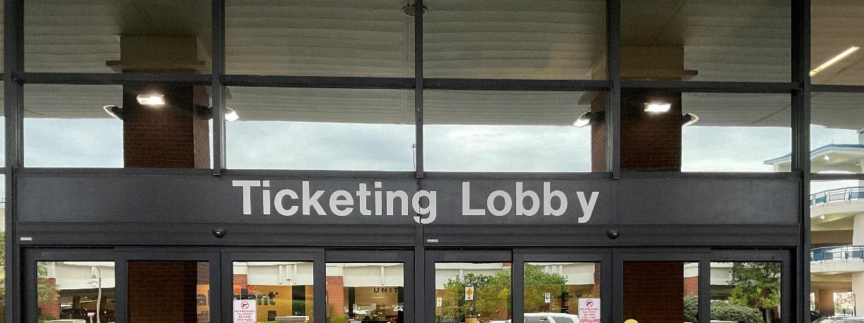

Source:CHA,2022.
2.1.7
Recommendations
Based on the inspections highlighted above, all main terminal exterior and vestibule sliding automatic doors are functioning as designed and, with continued maintenance, should continue to serve their required functions without replacement or major repair. The expected service life of an automatic sliding door unit is from 10 to 15 years but will vary based on intensity of use. The anodized surfaces of many door leaves are scuffed from contact with rolling luggage and luggage carts. This is an aesthetic issue that does not affect performance. Inspections and
// MASTER PLAN STUDY May, 2023 FINAL Architectural Assessment 2-3
Figure 2-1-1 – Typical Motorized Sliding Entry Door assembly

adjustments by qualified technicians are recommended, as these doors are subject to heavy use and their condition sets the tone for visitors to the airport.
2.1.8 Roof Assemblies
The roof of Building 1 consists of at least four different types of roof assembly – three types internally drained, low-slope membrane roofs with continuous insulation above deck and one with curved, standing seam metal roof panels. The age and condition of the assemblies varies.
Table 2-1-3 – Building 1 Asset Registry- Roof Assemblies
Roof-1-1 WhiteSBS Modified RoofA-Terminal TSAand CommercialSpace
Roof-1-2 WhiteSBS Modified RoofB-Terminal TicketCounters
Roof-1-3 WhiteSBS Modified RoofC-Terminal BagClaim N/A
Roof-1-4 WhiteSBS Modified RoofD-BagClaim DropOff N/A
Roof-1-5
Roof-1-6
WhiteSBS Modified RoofE-Lower ConcourseA&TSA
WhiteSBS Modified RoofF-Roofover BoilerRoomw/ CoolingTower
Roof-1-7 WhiteSBS Modified RoofG-Manager's LotUndercover Parking
Roof-1-8 WhiteSBS Modified (Pitched) RoofH-CheckPoint 1 N/A
Roof-1-9 WhiteSBS Modified RoofI-Checkpoint 1NexttoSkylight N/A
Roof-1-10
Roof-1-11
WhiteSBS Modified RoofJ-ConcourseA Walkway N/A
WhiteSBS Modified RoofK-Concourse A,GateAreas N/A
Roof-1-12 WhiteSBS Modified RoofF-TheClub N/A
Roof-1-13 WhiteSBS Modified RoofM-Between GateB1andB2 N/A
Roof-1-14 N/A RoofN-Between theClubandBag Make-up N/A
Roof-1-15 MembraneSheet RoofO-Baggage Firestone 2018
Roof-1-16 MembraneSheet RoofP-Concourse B
// MASTER PLAN STUDY May, 2023 FINAL Architectural Assessment 2-4
Asset Name Description Location Make Install Year
2012
N/A
2012
N/A
2012
2012
N/A 2012
N/A 2012
2012
N/A
2012
2012
2012
1999
2012
2012
2012
2007
N/A

Roof-1-17
Roof-1-18
Roof-1-19
MembraneSheet RoofQ–Concourse BRaisedLight
MonitorRoof N/A 2007
MembraneSheet RoofR-Concourse BbetweenGateB3 &B4RaisedLight MonitorRoof N/A 2007
StandingSeam Metal RoofS-Endof ConcourseB N/A 2007
Note:N/Aindicatesinformationnotverifiedinfield.
Note:SeeAppendixBforkeyplanofroofarealocations.
Source:CHA,2022.
2.1.9
Inspection Notes
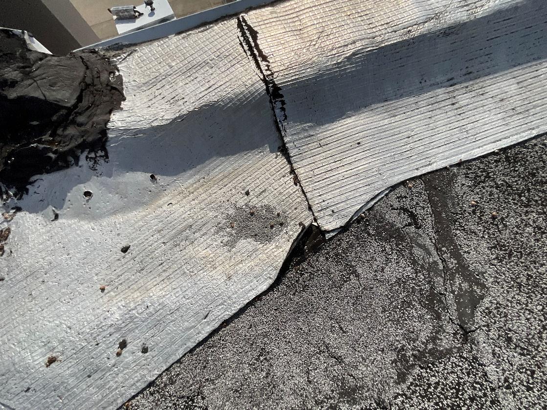
No active roof leaks were observed or reports in the main terminal, but as noted in the inspection reports, there is evidence of widespread, yet minor degradation of the roof assemblies. The most serious deficiencies and concerns are listed in the subsection following these notes. Intermittent small soft spots underfoot are evident in all roof assemblies. This softness suggests that water has defeated the membrane in small areas and damaged the underlying insulation. Large quantities of loose aggregate have come loose from SBS membranes and been deposited by wind and water in roof corners around roof drain sumps.
SBS, also known as styrene-butadiene-styrene, refers to the type of polymers that are added to the asphalt component of the roofing membrane. SBS is a thermoplastic elastomer that's resistant to harsh abrasions, making it an extremely long-lasting membrane when blended with bitumen, also known as asphalt. SBS membranes are similar to residential asphalt shingles in that they both contain a layer of aggregate embedded in a rubberized membrane layer. They are typically provided in short rolls. The aggregate layer is responsible for most of the roofing’s resistance to weather and solar radiation. When the aggregate becomes detached from the rubberized layer, the membrane will begin to become brittle and shrink. This will also allow moisture to penetrate further into the thickness of the membrane, causing further deterioration of the membrane.
Aggregate loss is most apparent in roof area 1-11. This area shows evident of repairs to the roof at drain sumps, roof edge cants and other varies areas of the roof. These repairs are failing as the repair material delaminated and de-adheres.
SBS roof areas also show evidence of standing water. Dirt and other fine particles have been deposited in pond-shaped areas in multiple flat areas of the roof. Some ponding is expected on most roofs, but the widespread evidence here suggests that water is frequently standing for long period of time. Standing water is detrimental to roof covering assemblies.
Mastic as used to cover seams between SBS sheets at roof edge cants and skylight and equipment curbs. At many locations across all roof areas, the top later of mastic has worn away, exposing the reinforcing mesh material embedded in the mastic.
// MASTER PLAN STUDY May, 2023 FINAL Architectural Assessment 2-5

Three areas of the terminal roof are covered by a smooth, light gray sheet membrane that appears to be either TPO (Thermoplastic polyolefin) or PVC (Polyvinyl chloride). The newest of these is at Roof-1-15, which was installed in 2018. As expected, this area is generally in very good condition, with only a few areas of softness underfoot at edges of sloping diamonds and crickets.
Roof areas 16, 17 and 18 have a similar smooth TPO or PVC membrane roof covering. These areas appear to be sound, but contain large, discolored areas of what appears to be lichen or mildew on the membrane surface. This is not desirable because it will encourage moisture to linger on the membrane which can lead to accelerated deterioration of the membrane. Provided below is a summary of the inspection:


Roof-1-11: Evidence of failing repairs shown in Figures 2-1-4, 2-1-5, 2-1-7 and 2-1-9.
Roof-1-16: Evidence of organic materials adhered to membrane surface shown in Figures 2-1-2 and 2-1-3

All SBS Roof Areas: Aggregate loss shown in Figures 2-1-6 and 2-1-7.
2-1-2 – Roof-1-16
Source:CHA,2022.
// MASTER PLAN STUDY May, 2023 FINAL Architectural Assessment 2-6
Figure

Source:CHA,2022.
Source:CHA,2022.
// MASTER PLAN STUDY May, 2023 FINAL Architectural Assessment 2-7
Figure 2-1-3 – Roof-1-16
Figure 2-1-4 – Roof-1-11

Figure 2-1-5 - Roof-1-11 - Evidence of Ponding

Source:CHA,2022.
Figure 2-1-6 – Roof-1-15 – Loose Aggregate from Adjacent SBS Roof Area

Source:CHA,2022.
// MASTER PLAN STUDY May, 2023 FINAL Architectural Assessment 2-8

2-1-7 – Roof-1-11 – Loose Aggregate Accumulation at Drain

Source:CHA,2022.
2-1-8 – Roof-1-3 – General View of SBS Roof Condition

Source:CHA,2022.
// MASTER PLAN STUDY May, 2023 FINAL Architectural Assessment 2-9
Figure
Figure


Source:CHA,2022.
2.1.10 Recommendations
It’s likely that the SBS roof areas are at or close to their warranty period, which are typically 10 to 15 years. Facilities staff should verify the warranties that are in place and consult with the manufacturer’s representative about specific measures that could prolong the life of the system. Early identification of signs of aging, such as aggregate loss and membrane shrinkage/stiffening, is critical in maximizing system life, which can be as long as 25 to 30 years. The oldest of these roof areas, Roof-1-10, should be evaluated first.
2.1.11 Motorized Hangar Doors
Hangar doors at the BGA vary dramatically in configuration, method of operation, size and condition. The expected service life of these doors also varies significantly and can range from 15 to 30 years, depending on maintenance, frequency of operation and exposure to extreme wind and weather damage. The hangar doors listed below were observed to determine general functional and aesthetic condition. Where possible, door operation was observed. Observations volunteered by hangar occupants about the condition and history of individual doors were also recorded.
// MASTER PLAN STUDY May, 2023 FINAL Architectural Assessment 2-10
Figure 2-1-9 – Roof-1-3 – Exposed Mesh and Cracked Mastic at SBS Membrane Joint

2.2 BUILDING 13 (MUSEUM)
2.2.1 Summary
Hangar 13 has three, large 6-panel motorized rolling exterior doors for airplane use.
2.2.2 Motorized Doors
The large exterior doors move in recessed tracks and rely on a motorized wheel to drag the doors across the floor.
Table 2-2-1 – Building 13 Asset Registry- Motorized Doors
Door-13-1
Door-13-3
Note:N/Aindicatesinformationnotverifiedinfield.
Source:CHA,2022.
2.2.3 Inspection Notes
Leading edge of doors and exterior sheet metal panels are prone to denting from normal use. Doors are large and drive mechanisms are prone to lose traction when the floor is wet. Weather seals are generally worn.

Door-13-1: Damage to exterior surface at multiple locations. Attempts to repair jamb seals are evident.

Door-13-2: Damage to panel edges at several locations. Evidence of attempted seal repair. Portions of seals missing at brackets.
2.2.4 Recommendations
It’s likely that these doors are beyond any standard warranty period, so they will rely on a system of scheduled inspection and maintenance to remain functional. It’s recommended that the Airport identify and contract with a qualified local company with specific expertise in maintenance and repair of this type of door to develop a plan for regular evaluation and maintenance.
// MASTER PLAN STUDY May, 2023 FINAL Architectural Assessment 2-11
Asset Name Description Location Make Install Year
OverlookingAirfield
RollingHanger
Norco 1988
OverlookingAirfield
Door-13-2 RollingHanger
Norco 1988
RollingHanger OverlookingAirfield Norco 1988

Figure 2-2-1 – Door-13-1 – Typical Sheet metal damage to Door Leading Edge

Source:CHA,2022.
2.3 BUILDING 15 (HANGAR 15)
2.3.1 Summary
Hangar 15, used by Thoroughbred, has one motorized rolling exterior door for airplane use.
2.3.2 Motorized Doors
The large exterior door panels move in recessed tracks and rely on a motorized wheel to drag the doors across the floor. The second door is a single, interior small coiling overhead unit.
// MASTER PLAN STUDY May, 2023 FINAL Architectural Assessment 2-12

Table 2-3-1 – Building 15 Asset Registry- Motorized Doors
Door-15-1 RollingHanger OverlookingAirfield Cutler-Hammer, RollingDoor 1982
Door15-2 OverheadCoiling Interior OverheadDoor 1982
Note:N/Aindicatesinformationnotverifiedinfield.
2.3.3 Inspection Notes
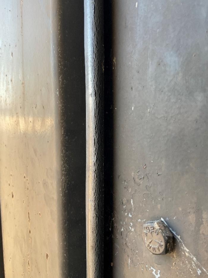
Interior door is functional. In general, these doors show signs of wear and tear that reflect their age and heavy use. No safety hazards were observed, and damage and deficiencies are limited to aesthetic concerns and lack of weathertightness due to damage and deterioration of flexible weather seals at door perimeters. The resulting heat loss and minor water infiltration are assumed to be minor concerns to the occupants of industrial spaces like hangars.


Door-15-1: Rust on steel at door panel ends.
Door-15-1: Safety Edges, Weather Seals/Brushes
Door-15-1: Users report this door recently blew off its track in a high wind.
Figure 2-3-1 – Door-13-1 – Weather seal damage
Source:CHA,2022.
// MASTER PLAN STUDY May, 2023 FINAL Architectural Assessment 2-13
Asset Name Description Location Make Install Year

2.3.4 Recommendations
It’s likely that these doors are beyond any standard warranty period, so they will rely on a system of scheduled inspection and maintenance to remain functional. It’s recommended that the Airport identify and contract with a qualified local company with specific expertise in maintenance and repair of this type of door to develop a plan regular evaluation and maintenance.
2.4 BUILDING 16 (HANGAR 16)
2.4.1 Summary
Hangar 16, is used by TACAir and Thoroughbred, has one large panelized motorized rolling exterior door for airplane use.
2.4.2 Motorized Doors
The large exterior door moves in a recessed track and rely on a motorized wheel to drag the door across the floor.
Table 2-4-1 –Building 16 - Asset Registry - Motorized Doors
Door-16-1 RollingHanger OverlookingAirfield N/A 1970 Note:N/Aindicatesinformationnotverifiedinfield.
Source:CHA,2022.
2.4.3 Inspection Notes
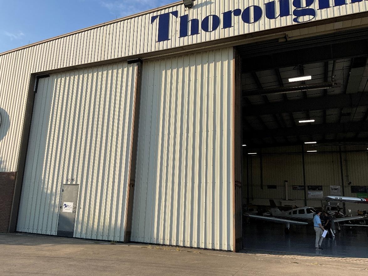
In general, these doors show signs of wear and tear that reflect their age and heavy use. No safety hazards were observed, and damage and deficiencies are limited to aesthetic concerns and lack of weathertightness due to damage and deterioration of flexible weather seals at door perimeters. The resulting heat loss and minor water infiltration are assumed to be minor concerns to the occupants of industrial spaces like hangars.


Door-16-1: Rust on steel at door panel ends.
Door-16-1: Safety Edges, Weather Seals/Brushes
// MASTER PLAN STUDY May, 2023 FINAL Architectural Assessment 2-14
Asset Name Description Location Make Install Year

Source:CHA,2022.
2.4.4 Recommendations
It’s likely that these doors are beyond any standard warranty period, so they will rely on a system of scheduled inspection and maintenance to remain functional. It’s recommended that the Airport identify and contract with a qualified local company with specific expertise in maintenance and repair of this type of door to develop a plan regular evaluation and maintenance.
2.5 BUILDING 19 (HANGAR 19)
2.5.1 Summary
Hangar 19, used by TACAir and Thoroughbred, with one large panelized motorized rolling exterior door for airplane use.
2.5.2 Motorized Doors
The large exterior door moves in recessed track and rely on a motorized wheel to drag the door across the floor.
// MASTER PLAN STUDY May, 2023 FINAL Architectural Assessment 2-15
Figure 2-4-1 – Door-16-1 – General view

Table 2-5-1 – Building 19 - Asset Registry - Motorized Doors
Door-19-1
CoilingOverhead OverlookingAirfield N/A 1977
Note:N/Aindicatesinformationnotverifiedinfield.
Source:CHA,2022.
2.5.3 Inspection Notes

Door-19-1: Minor corrosion on bottom rail does not present a functional concern and expected where steel is in long-term contact with pavement.
Figure 2-5-1 – Door-19-1 –General view

Source:CHA,2022.
2.5.4 Recommendations
It’s likely that these doors are beyond any standard warranty period, so they will rely on a system of scheduled inspection and maintenance to remain functional. It’s recommended that the Airport identify and contract with a qualified local company with specific expertise in maintenance and repair of this type of door to develop a plan for regular evaluation and maintenance. Corrosion should be monitored to determine if it has progressed to the point where functionality is affected.
// MASTER PLAN STUDY May, 2023 FINAL Architectural Assessment 2-16
Asset Name Description Location Make Install Year

2.6 BUILDING 25
2.6.1 Summary
Motorized, hinged horizontal hangar door in good operating condition with minor damage due to normal wear and tear.
2.6.2 Motorized Doors
Motorized, hinged horizontal hangar door.
Table 2-6-1 – Building 25 - Asset Registry - Motorized Doors
Door-25-1 HingedHorizontal OverlookingAirfield N/A 1995
Note:N/Aindicatesinformationnotverifiedinfield.
Source:CHA,2022.
2.6.3 Inspection Notes

Door-25-1: Damage to insulation panels.
Figure 2-6-1 – Door-25-1 –General view


Source:CHA,2022.
// MASTER PLAN STUDY May, 2023 FINAL Architectural Assessment 2-17
Asset Name Description Location Make Install Year

2.6.4 Recommendations
It’s likely that these doors are beyond any standard warranty period, so they will rely on a system of scheduled inspection and maintenance to remain functional. It’s recommended that the Airport identify and contract with a qualified local company with specific expertise in maintenance and repair of this type of door to develop a plan for regular evaluation and maintenance.
2.7 BUILDING 26
2.7.1 Summary
Motorized, hinged horizontal hangar door in good operating condition with minor damage due to normal wear and tear.
2.7.2 Motorized Doors
Motorized, hinged horizontal hangar door.
Table 2-7-1 – Building 26 - Asset Registry - Motorized Doors
Door-26-1 HingedHorizontal OverlookingAirfield N/A
Note:N/Aindicatesinformationnotverifiedinfield.
Source:CHA,2022.
2.7.3 Inspection Notes

Door-26-1: Minimal damage to trim at bottom of door
Figure 2-7-1 – Door-26-1 –General view

Source:CHA,2022.
// MASTER PLAN STUDY May, 2023 FINAL Architectural Assessment 2-18
Asset Name Description Location Make Install Year
1995

2.7.4 Recommendations
It’s likely that these doors are beyond any standard warranty period, so they will rely on a system of scheduled inspection and maintenance to remain functional. It’s recommended that the Airport identify and contract with a qualified local company with specific expertise in maintenance and repair of this type of door to develop a plan for regular evaluation and maintenance.
2.8 BUILDING 27
2.8.1 Summary
Motorized, hinged horizontal hangar door in good operating condition with minor damage due to normal wear and tear.
2.8.2 Motorized Doors
Motorized, hinged horizontal hangar door.
Door-27-1 HingedHorizontal OverlookingAirfield N/A 1995 Note:N/Aindicatesinformationnotverifiedinfield.
Source:CHA,2022.
2.8.3 Inspection Notes

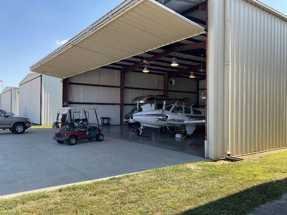
Door-27-1: Dents to exterior side metal wall panel. Minor corrosion at panel edges.
Source:CHA,2022.
// MASTER PLAN STUDY May, 2023 FINAL Architectural Assessment 2-19
Asset Name Description Location Make Install Year
Table 2-8-1 – Building 27 - Asset Registry - Motorized Doors
Figure 2-8-1 – Door-27-1 – General view

2.8.4 Recommendations
It’s likely that these doors are beyond any standard warranty period, so they will rely on a system of scheduled inspection and maintenance to remain functional. It’s recommended that the Airport identify and contract with a qualified local company with specific expertise in maintenance and repair of this type of door to develop a plan for regular evaluation and maintenance. Cable operated doors are prone to imbalance and require frequent adjustment.
2.9 BUILDING 28
2.9.1 Summary
Motorized, hinged horizontal hangar door in good operating condition with minor damage due to normal wear and tear. Cable management needs to be corrected to avoid damage to the door.
2.9.2 Motorized Doors
Motorized, hinged horizontal hangar door.
HingedHorizontal OverlookingAirfield N/A 1995 Note:N/Aindicatesinformationnotverifiedinfield.Source:CHA,2022.
2.9.3 Inspection Notes

Door-28-1: Bottom seal deteriorated. Loose cables cause operating problems, potential to damage insulation.

Source:CHA,2022.
// MASTER PLAN STUDY May, 2023 FINAL Architectural Assessment 2-20
Asset Name Description Location Make Install Year Door-28-1
Table 2-9-1 – Building 28 - Asset Registry - Motorized Doors
Figure 2-9-1 – Door-28-1 – General view

2.9.4 Recommendations
It’s likely that these doors are beyond any standard warranty period, so they will rely on a system of scheduled inspection and maintenance to remain functional. It’s recommended that the Airport identify and contract with a qualified local company with specific expertise in maintenance and repair of this type of door to develop a plan for regular evaluation and maintenance. Cable operated doors are prone to imbalance and require frequent adjustment.
2.10 BUILDING 29
2.10.1 Summary
Motorized, hinged horizontal hangar door.
2.10.2 Motorized Doors
Motorized, hinged horizontal hangar door.
Table 2-10-1 –Building 29 - Asset Registry - Motorized Doors
Door-29-1 HingedHorizontal OverlookingAirfield N/A 1995
Note:N/Aindicatesinformationnotverifiedinfield.
2.10.3 Inspection Notes
Door is in good condition for its age and is fully operational.

Source:CHA,2022.
// MASTER PLAN STUDY May, 2023 FINAL Architectural Assessment 2-21
Asset Name Description Location Make Install Year
Figure 2-10-1 – Door-29-1 – General view

2.10.4 Recommendations
It’s likely that these doors are beyond any standard warranty period, so they will rely on a system of scheduled inspection and maintenance to remain functional. It’s recommended that the Airport identify and contract with a qualified local company with specific expertise in maintenance and repair of this type of door to develop a plan for regular evaluation and maintenance. Cable operated doors are prone to imbalance and require frequent adjustment.
2.11 BUILDING 45
2.11.1 Summary
Hydraulically powered, motorized, hinged horizontal hangar doors, recently installed and in good operating condition.
2.11.2 Motorized Doors
Hydraulically powered, motorized, hinged horizontal hangar doors.
Table 2-11-1 – Building 45 - Asset Registry - Motorized Doors
Door-45-1
Door-45-2
Door-45-3
Door-45-4
Door-45-5
MotorizedHydraulic, HingedHorizontal Overlooking Airfield
MotorizedHydraulic, HingedHorizontal Overlooking Airfield
MotorizedHydraulic, HingedHorizontal Overlooking Airfield
MotorizedHydraulic, HingedHorizontal Overlooking Airfield
MotorizedHydraulic, HingedHorizontal Overlooking Airfield
StructuralIntegrity Engineering 2021
StructuralIntegrity Engineering 2021
StructuralIntegrity Engineering 2021
StructuralIntegrity Engineering 2021
StructuralIntegrity Engineering 2021 Source:CHA,2022.
2.11.3 Inspection Notes
Doors are fully functional and in “as new” condition.
// MASTER PLAN STUDY May, 2023 FINAL Architectural Assessment 2-22
Asset Name Description Location Make Install Year

Figure 2-11-1 – Door-45-1 – General view – Typical All Doors in Building 45

Source:CHA,2022.
Figure 2-11-2 – Door-45-1 – Hydraulic Unit – Typical All Doors in Building 45

Source:CHA,2022.
// MASTER PLAN STUDY May, 2023 FINAL Architectural Assessment 2-23

2.11.4 Recommendations
No corrective maintenance is required for these doors. A regular schedule of inspection and preventative maintain is recommended to maintain good operational condition.
2.12 BUILDING 51
2.12.1 Summary
Building 51 contains multiple, similar motorized coiling overhead doors at interior and exterior locations manufactured by Cornell Doors.
2.12.2 Motorized Doors
Motorized coiling overhead doors
Table 2-12-1 – Building 51 - Asset Registry - Motorized Doors
Door-51-1 CoilingOHD ESD20 Exterior Cornell 2015
Door-51-2
Door-51-3
Door-51-4
Door-51-5
Door-51-6
Door-51-7
Door-51-8
Door-51-9
CoilingOverhead InteriorLoadDock Cornell 2015
CoilingOverhead InteriorToolCrib Cornell 2015
CoilingOverhead InteriorVehicleStorage Cornell 2015
CoilingOverhead ExteriorMaintGar Cornell 2015
CoilingOverhead ExteriorWashBay Cornell 2015
CoilingOverhead ExteriorVehicleStorage Cornell 2015
CoilingOverhead ManuallyDoor N/A N/A
CoilingOverhead ExteriorMaintenanceBay Cornell 2015
Door-51-10 CoilingOverhead ExteriorMaintenanceBay Cornell 2015
Door-51-11
Door-51-12
Door-51-13
Door-51-14
Door-51-15
Door-51-16
Door-51-17
CoilingOverhead ExteriorMaintenanceBay Cornell 2015
CoilingOverhead ExteriorMaintenanceBay Cornell 2015
CoilingOverhead ExteriorSaltStorage Cornell 2015
CoilingOverhead Ext.De-icerStorage Cornell 2015
CoilingOverhead Ext.De-icer/Pesticide Cornell 2015
CoilingOverhead Ext.PaintStorage Cornell 2015
CoilingOverhead Ext.Lumber/FieldMaintenance Storage Cornell 2015
Door-51-18 CoilingOverhead Ext.AtticStockStorage Cornell 2015
Door-51-19 CoilingOverhead Ext.ElectStor Cornell 2015 Source:CHA,2022.
2.12.3 Inspection Notes
Most doors were recently installed and in good operating condition, with the exception of the doors and conditions noted below. Steel angle bottom rails in contact with the ground typically have surface corrosion, that does not affect function.
// MASTER PLAN STUDY May, 2023 FINAL Architectural Assessment 2-24
Asset Name Description Location Make Install Year


Door-51-1: Minor corrosion on bottom rail.
Door 51-2: Small signs of impact to door curtain at 2 and 4 ft above floor
Door 51-6: Significant corrosion on all door components due to humidity/moisture in room.
Door 51-7: Incomplete bottom seal at corner. Bottom seal is damaged at several locations. Brushes at head are damaged.
Door 51-13 Damaged bottom rail. Severe corrosion at bottom 2 ft of exterior side of door.

Source:CHA,2022.
// MASTER PLAN STUDY May, 2023 FINAL Architectural Assessment 2-25
Figure 2-12-1 – Door-51-1 – General view – Minor Damage to Door Curtain

Figure 2-12-2 – Door-51-5 – General view – Typical Exterior Door

Source:CHA,2022.
Figure 2-12-3 – Door-51-6 – Corrosion at Bottom Rail

Source:CHA,2022.
// MASTER PLAN STUDY May, 2023 FINAL Architectural Assessment 2-26


Source:CHA,2022.

Source:CHA,2022.
// MASTER PLAN STUDY May, 2023 FINAL Architectural Assessment 2-27
Figure 2-12-4 – Door-51-6 – Corrosion at Bottom Rail
Figure 2-12-5 – Door-51-13 – Corrosion at Salt Storage Door

2.12.4 Recommendations
Most doors within building 51 are in good operating condition. The largest concerns are with the condition of door perimeter seals and brushes which are beginning to show signs of wear and tear on frequently used doors and corrosion at wash bay and salt storage rooms. It’s recommended that BGA contact a qualified Cornell service provider to provide a recommendation on corrective action and suitable replacement of damaged components to maintain these doors in operational condition.
2.13 BUILDING 57
2.13.1 Summary
Building 57 is the aircraft rescue and firefighting (ARFF) station which contains six similar motorized sectional overhead doors with glazed and opaque panels at emergency vehicle bays. Doors were recently installed and appear to be in as-new condition.
2.13.2 Motorized Doors
Motorized sectional overhead doors Table 2-13-1 – Building 57 - Asset Registry - Motorized Doors
northmostdoor, facingairfield
Door-57-5 SectionalOHD BayDoorEsouthmostdoor, facingawayfrom airfield
Door-57-6 SectionalOHD BayDoorFnorthmostdoor, facingawayfrom airfield
Source:CHA,2022.
2.13.3 Inspection Notes
Doors were recently installed and appear to be in as-new condition.
// MASTER PLAN STUDY May, 2023 FINAL Architectural Assessment 2-28
Asset Name Description Location Make Install Year
SectionalOHD BayDoorASouthmostdoor, facingairfield OverheadDoor Company 2020 Door-57-2 SectionalOHD BayDoorB-facing airfield OverheadDoor Company 2020 Door-57-3 SectionalOHD BayDoorC-facing
OverheadDoor Company 2020
SectionalOHD
OverheadDoor
2020
Door-57-1
airfields
Door-57-4
BayDoorD-
Company
OverheadDoor
2020
Company
OverheadDoor
2020
Company

Figure 2-13-1 – General view – Typical Fire Station Door

Source:CHA,2022.
2.13.4 Recommendations
No corrective maintenance is required for these doors. A regular schedule of inspection and preventative maintenance is recommended to maintain good operational condition.
2.14 BUILDING 106 (4480 GUMBERT ROAD)
2.14.1 Summary
Building 106 contains 13 hangar doors. These doors consist of two horizontal panels, hinged horizontally. A hinged man-door is integral to the lower horizontal panel.
2.14.2 Motorized Doors
Motorized sectional overhead doors
Table 2-14-1 – Building 106 - Asset Registry - Motorized Doors
Door-106-1
HingedHorizontal DoorA Erectatube 2015
Door-106-2 HingedHorizontal DoorB Erectatube 2015
Door-106-3 HingedHorizontal DoorC Erectatube 2015
Door-106-4 HingedHorizontal DoorD Erectatube 2015
Door-106-5
HingedHorizontal DoorE Erectatube 2015
Door-106-6 HingedHorizontal DoorF Erectatube 2015
// MASTER PLAN STUDY May, 2023 FINAL Architectural Assessment 2-29
Asset Name Description Location Make Install Year

Door-106-7
Door-106-8
Door-106-9
Door-106-10
Door-106-11
Door-106-12
Door-106-13
HingedHorizontal DoorG Erectatube 2015
HingedHorizontal DoorH Erectatube 2015
HingedHorizontal DoorI Erectatube 2015
HingedHorizontal DoorJ Erectatube 2015
HingedHorizontal DoorK Erectatube 2015
HingedHorizontal DoorL Erectatube 2015
HingedHorizontal DoorM Erectatube 2015
Source:CHA,2022.
2.14.3 Inspection Notes
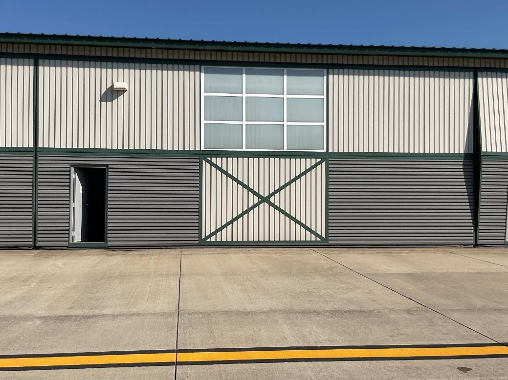
Doors were recently installed and appear to be in good condition. At multiple locations, gaskets at the bottom of door panels are displaced, detached or damaged. Significant algae and mildew growth is present at the lower 12” of multiple doors on the north side of Building 106.

Door-106-2: Evidence of rodent infestation.
Figure 2-14-1 – General view – Building 106
Source:CHA,2022.
// MASTER PLAN STUDY May, 2023 FINAL Architectural Assessment 2-30

Figure 2-14-2 – Typical Displaced Bottom Gaskets – Building 106

Source:CHA,2022.
Figure 2-14-3 – Evidence of Rodents – Building 106
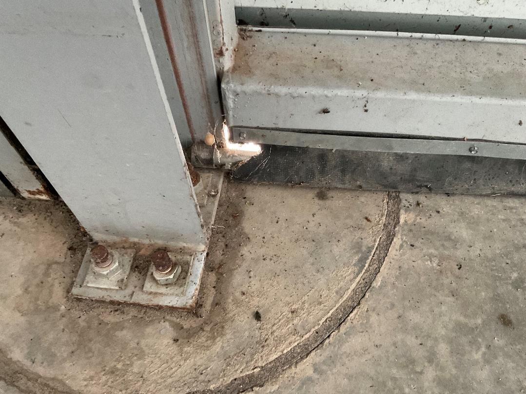
Source:CHA,2022.
// MASTER PLAN STUDY May, 2023 FINAL Architectural Assessment 2-31

Figure 2-14-4 – Evidence of Rodents – Building 106
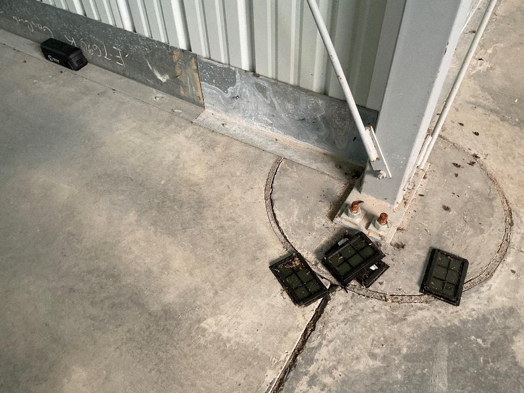
Source:CHA,2022.
Figure 2-14-5 – Algae and Mildew at Base of Door Panel – Building 106

Source:CHA,2022.
// MASTER PLAN STUDY May, 2023 FINAL Architectural Assessment 2-32

2.14.4 Recommendations
These doors are generally in good functional condition. As with many other doors of this type, maintaining weather seals at door perimeter is difficult. It’s recommended that BGA contact a qualified service provider to determine corrective actions and suitable replacement of damaged components to maintain these doors in operational condition. Over time, failure of weather seals will contribute to the deterioration of other building components. Removal of algae and mildew with a power washer and suitable biocide is recommended. This begins as an aesthetic problem but can contribute to deterioration of door materials over time.
2.15 BUILDING 107 (4476 GUMBERT ROAD)
2.15.1 Summary
Building 107 contains 13 hangar doors. These doors consist of two horizontal panels, hinged horizontally. A hinged man-door is integral to the lower horizontal panel.
2.15.2 Motorized Doors
Motorized sectional overhead doors
Table 2-15-1 – Building 107 - Asset Registry - Motorized Doors
Door-107-1
Door-107-2
Door-107-3
Door-107-4
Door-107-5
Door-107-6
Door-107-7
Door-107-8
Door-107-9
Door-107-10
Door-107-11
Door-107-12
Door-107-13
HingedHorizontal DoorA Erectatube 2015
HingedHorizontal DoorB Erectatube 2015
HingedHorizontal DoorC Erectatube 2015
HingedHorizontal DoorD Erectatube 2015
HingedHorizontal DoorE Erectatube 2015
HingedHorizontal DoorF Erectatube 2015
HingedHorizontal DoorG Erectatube 2015
HingedHorizontal DoorH Erectatube 2015
HingedHorizontal DoorI Erectatube 2015
HingedHorizontal DoorJ Erectatube 2015
HingedHorizontal DoorA Erectatube 2015
HingedHorizontal DoorA Erectatube 2015
HingedHorizontal DoorA Erectatube 2015
Source:CHA,2022.
2.15.3 Inspection Notes
Doors were recently installed and appear to be in good condition. At multiple locations, gaskets at the bottom of door panels are displaced, detached or damaged. Significant algae and mildew growth is present at the lower 12” of multiple doors on the north side of Building 107.
// MASTER PLAN STUDY May, 2023 FINAL Architectural Assessment 2-33
Asset Name Description Location Make Install Year


Door-107-6: Door appears to be hung up on jamb tracks and unable to close completely. track. This problem is evident to some degree on many doors any may be a design issue.
2-15-1 – Jamb of Door 107-6

Source:CHA,2022.
2.15.4 Recommendations
These doors are generally in good functional condition. As with many other doors of this type, maintaining weather seals at door perimeter is difficult. It’s recommended that BGA contact a qualified service provider to determine corrective actions and suitable replacement of damaged components to maintain these doors in operational condition. Over time, failure of weather seals will contribute to the deterioration of other building components. Removal of algae and mildew with a power washer and suitable biocide is recommended. This begins as an aesthetic problem but can contribute to deterioration of door materials over time.
2.16 BUILDING 108 (4472 GUMBERT ROAD)
2.16.1 Summary
Building 108 contains 5 hangar doors. These doors consist of two horizontal panels, hinged horizontally. A hinged man-door is integral to the lower horizontal panel. Doors were recently installed and appear to be in good operating condition.
// MASTER PLAN STUDY May, 2023 FINAL Architectural Assessment 2-34
Figure

2.16.2 Motorized Doors
Motorized sectional overhead doors.
Table 2-16-1 – Building 108 - Asset Registry - Motorized Doors
Asset Name
Door-108-1
Door-108-2
Door-108-3
Door-108-4
Door-108-5
HingedHorizontal DoorA
HingedHorizontal DoorB
HingedHorizontal DoorC
HingedHorizontal DoorD
HingedHorizontal DoorE
Source:CHA,2022.
2.16.3 Inspection Notes
Hi-foldDoorCorpH 2018
Hi-foldDoorCorpH 2018
Hi-foldDoorCorpH 2018
Hi-foldDoorCorpH 2018
Hi-foldDoorCorpH 2018
Doors were recently installed and appear to be in good functional condition. Spray-applied thermal insulation has been applied to doors in hanger bays where air conditioning has been added to Doors 108-1, 108-2, 108-3 and 108-4. Evidence of condensation or water infiltration through translucent panels was observed on the surface of insulation at 108-4. Condensation is the result of humid air entering the hangar at the perimeter of opaque panels or through poorly sealed door perimeter gaskets and encountering cooled interior air. Several weather seals at the ends of bottom rails are displaced.
Figure 2-16-1 – Black Spray-applied Insulation at interior of Door 108-1

Source:CHA,2022.
// MASTER PLAN STUDY May, 2023 FINAL Architectural Assessment 2-35
Description Location Make Install Year

2-16-2 – General View of Typical Door at Building 108

Source:CHA,2022.
Figure 2-16-3 – General View of Typical Door at Building 108

Source:CHA,2022.
// MASTER PLAN STUDY May, 2023 FINAL Architectural Assessment 2-36
Figure

2.16.4 Recommendations
These doors are generally in good functional condition. As with many other doors of this type, maintaining weather seals at door perimeter is difficult. It’s recommended that BGA contact a qualified service provider to determine corrective actions and suitable replacement of damaged components to maintain these doors in operational condition. Over time, failure of weather seals will contribute to the deterioration of other building components.
2.17 BUILDING 109 (4464 GUMBERT ROAD)
2.17.1 Summary
Building 109 contains two motorized doors. One large sliding hanger door, and one small receiving door.
2.17.2 Motorized Doors
Motorized overhead coiling door; motorized sliding hangar door.
Table 2-17-1 – Building 109 - Asset Registry - Motorized Doors
Door-109-1 MotorizesSliding FacingAirfield N/A 2018
Door-109-2 OverheadCoiling FacingAirfield Raynor 2018
Note:N/Aindicatesinformationnotverifiedinfield. Source:CHA,2022.
2.17.3 Inspection Notes

Door-109-1: User reports that of the four lateral sliding panels, only one has a drive mechanism. This drive wheel frequently slips on its rail in the winter and is unable to pull the three other panels open or closed.

Door-109-2: Minor damage to bottom seal at both ends.
// MASTER PLAN STUDY May, 2023 FINAL Architectural Assessment 2-37
Asset Name Description Location Make Install Year

2-17-1 – General view – Door-109-1

Source:CHA,2022.
2-17-2 – Bottom Seal – Door 109-2

Source:CHA,2022.
// MASTER PLAN STUDY May, 2023 FINAL Architectural Assessment 2-38
Figure
Figure

2.17.4 Recommendations
These doors are generally in good condition. BGA should address the specific user complaint about function of large, motorized sliding door 119-1 and determine if it’s still under the original warranty. The noted damage to bottom seal is minor but should be evaluated and repaired promptly. Over time, failure of weather seals will contribute to the deterioration of other building components.
2.18 BUILDING 70 (ARFF TRAINING CENTER)
2.18.1 Summary
Building 70 has a black, adhered membrane roof covering that’s assumed to be PVC.
2.18.2 Roof Assembly
Adhered membrane.
Table 2-18-1 – Building 13 Asset Registry- Roof Assembly
Roof-70-1 BlackPVC ARFFTraining N/A 2017
Note:N/Aindicatesinformationnotverifiedinfield.
Source:CHA,2022.
2.18.3 Inspection Notes
Membrane appears to be in good condition, aside from the issues listed below, and no active roof leaks were reported.

Roof 70-1 Large amounts of leaves and organic matter accumulating on the roof. Wrinkling of membrane at back of parapets and roof field suggests possible adhesion failures and stress on the membrane. Construction at thru-wall scuppers and steel ladders is significant and appears to have been repaired. Minor ponding was observed, as well as evidence of larger dried-up ponding locations.
// MASTER PLAN STUDY May, 2023 FINAL Architectural Assessment 2-39
Asset Name Description Location Make Install Year

Figure 2-18-1 – Debris Accumulation
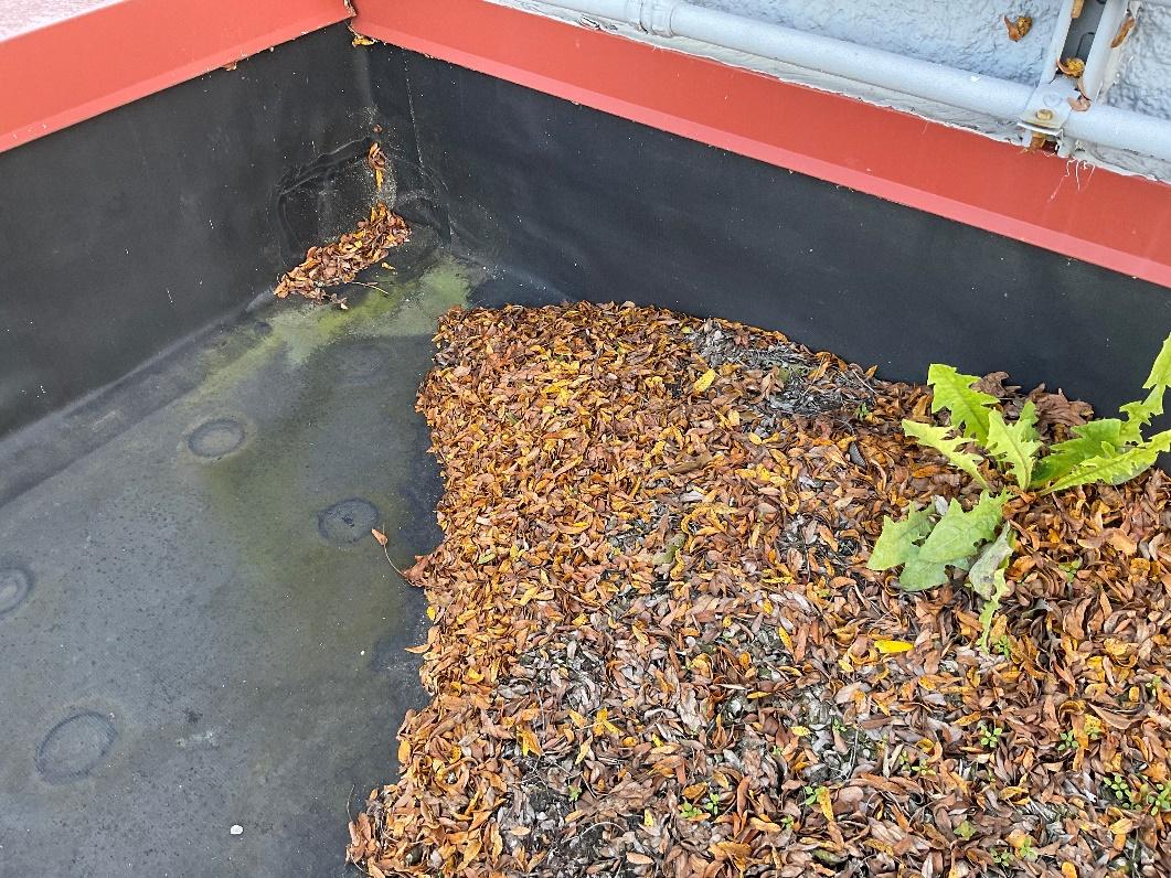
Source:CHA,2022.
Figure 2-18-2 – Evidence of Long-Term Ponding
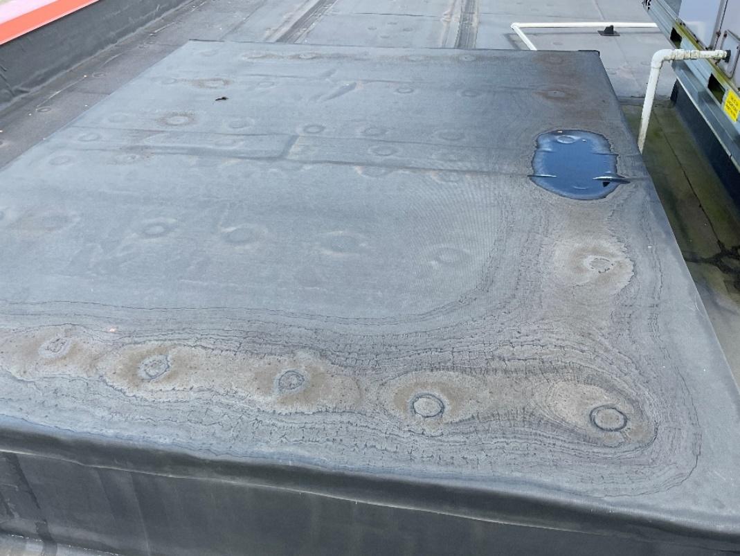
Source:CHA,2022.
// MASTER PLAN STUDY May, 2023 FINAL Architectural Assessment 2-40


Source:CHA,2022.

Source:CHA,2022.
// MASTER PLAN STUDY May, 2023 FINAL Architectural Assessment 2-41
Figure 2-18-3 – Wrinkles in the Membrane
Figure 2-18-4 – Wrinkles in the Membrane


Source:CHA,2022.

Source:CHA,2022.
// MASTER PLAN STUDY May, 2023 FINAL Architectural Assessment 2-42
Figure 2-18-5 – Steel Ladder Attachment
Figure 2-18-6 – Condition at Thru-wall Scupper Drain

2.18.4 Recommendations
Roof-70-1 is in good condition, but some observed conditions raise concerns about long-term performance. Organic debris should be cleared from the roof on a regular basis to avoid active plant growth, which can damage the membrane. Length of ponding should be observed, documented, and then reported to the roof manufacturer to confirm that the roof is not holding water longer than allowed by the manufacturer. Excessive standing water can cause premature seam failure. Previously repaired condition should also be monitored. They represent know vulnerabilities that may be prone to future failure.
// MASTER PLAN STUDY May, 2023 FINAL Architectural Assessment 2-43

3 MECHANICAL ASSESSMENT (HVAC)
The Mechanical condition assessment was conducted on September 20th – 22nd, 2022 with the purpose of logging Mechanical assets in the Airport’s asset management software (Aerosimple) and completing a baseline condition inspection of the equipment. Condition assessments were conducted visually in nature and did not include any performance verification testing. Condition ratings and recommendations were determined based on visual inspection and equipment installation date when compared to industry standard life expectancies as outlined by the American Society of Heating Refrigeration and Air Conditioning Engineers (ASHRAE) and referenced in Appendix C. The systems covered in this section include rooftop package units, split system outdoor units, heating hot water boilers, chilled water systems and indoor air handling units. The areas surveyed during the visit were limited to dedicated Mechanical spaces and roof equipment, indoor units above ceiling and in occupiable space are omitted from this report.
3.1 BUILDING 1 (TERMINAL BUILDING)
3.1.1 Summary
Building 1 is considered the Airport’s main terminal building including concourse areas, passenger processing areas, and support office spaces. The equipment inspected during the visit was located within the building’s (3) boiler rooms and on various roof levels. Boiler room 1 contains two natural gas condensing boilers and one dual-fuel boiler which serves as a backup boiler to the primary condensing boilers. Heating hot water boilers are the primary heating energy source for the facility. A number of floor-mounted end suction pumps which distribute heating and cooling water to the various terminal devices located throughout the building are also located in boiler room 1. A recently installed water-cooled chiller with associated cooling tower located on the roof provide a portion of the facility’s cooling energy. Boiler room 2 contains two natural gas, firetube boilers installed in 1989. Boiler room 3 consists of two conventional, copper-fin, natural gas boilers and two variable speed air handling units with chilled water cooling coils, hot water heating coils, and associated inline return fans which provide ventilation air to the terminal building. An air-cooled water chiller on the roof serves the additional cooling units in Concourse B. The rest of the rooftop equipment consists of rooftop air handling units and split system cooling units serving the space conditioning needs of the airport terminals below. The kitchen hoods in the terminal’s restaurants are served by a roof-mounted makeup air system with the former unit disconnected and abandoned alongside on the roof. The airline club lounge and club conference room are served by indoor air handling units located in dedicated Mechanical rooms adjacent to the space. The assets and accompanying information regarding make, location and year of installation are summarized in the table below.
// MASTER PLAN STUDY May, 2023 FINAL Mechanical Assessment 3-1

Table 3-1-1 – Building 1 Asset Registry
HVAC-1-1 Boiler BoilerRoom2 CleaverBrooks 1989
HVAC-1-2 Boiler BoilerRoom1 Lochinvar(Crest) 2014
HVAC-1-3 Boiler BoilerRoom1 Lochinvar(Crest) 2014
HVAC-1-4 Boiler BoilerRoom1 Weil-McClain 2014
HVAC-1-5 Boiler BoilerRoom3 Lochinvar 2007
HVAC-1-6 Boiler BoilerRoom3 Lochinvar 2007
HVAC-1-7 Chiller ConcourseB McQuay 2007
HVAC-1-8 Chiller BoilerRoom1 Smardt 2022
HVAC-1-9 CoolingTower BaggageClaim (Exterior) BaltimoreAircoilCo 2008
HVAC-1-10 CoolingTower BaggageClaim (Exterior) BaltimoreAircoilCo 2008
HVAC-1-11 CoolingTower BoilerRoom1 (Roof) Marley 2014
HVAC-1-12 AirHandlingUnit BoilerRoom3 McQuay 2006
HVAC-1-13 AirHandlingUnit BoilerRoom3 McQuay 2006
HVAC-1-14 N/A NotLocated N/A N/A
HVAC-1-15 RooftopUnit Terminal(Roof) Carrier 2009
HVAC-1-16 RooftopUnit Terminal(Roof) Mammoth 2015
HVAC-1-17 RooftopUnit Terminal(Roof) Mammoth 2015
HVAC-1-18 RooftopUnit Terminal(Roof) Mammoth 2015
HVAC-1-19 RooftopUnit Terminal(Roof) Mammoth 2015
HVAC-1-20 RooftopUnit Terminal(Roof) Trane 2015
HVAC-1-21 RooftopUnit Terminal(Roof) Trane 2015
HVAC-1-22 AirHandlingUnit Club(Mechanical Room) McQuay 2008
HVAC-1-23 AirHandlingUnit Club(Mechanical Room) McQuay 2008
HVAC-1-24 RooftopUnit Terminal(LowRoof) Aaon 2002
HVAC-1-25 RooftopUnit IT(Roof) Goodman 2008
HVAC-1-26 CondensingUnit Terminal(LowRoof) Trane 2019
HVAC-1-27 CondensingUnit Terminal(LowRoof) Trane 2019
HVAC-1-28 CondensingUnit Terminal(LowRoof) Trane 2019
HVAC-1-29 CondensingUnit Terminal(LowRoof) Trane 2019
HVAC-1-30 CondensingUnit Terminal(Roof) Liebert 2009
HVAC-1-31 CondensingUnit Terminal(Roof) Liebert 2010
HVAC-1-32 CondensingUnit Terminal(Roof) Liebert 2010
HVAC-1-33 SplitSystem ClubConference (Roof) York 2009
HVAC-1-34 Pumps BoilerRoom1 Bell&Gossett N/A
HVAC-1-35 Boiler BoilerRoom2 CleaverBrooks 1989
HVAC-1-36 CondensingUnit Terminal(Roof) Liebert 2010
HVAC-1-37 MakeupAirUnit Kitchen(Roof) Captivaire 1989
HVAC-1-38 MakeupAirUnit Kitchen(Roof) Captivaire 2021
HVAC-1-39 SplitSystem Terminal(LowRoof) Mitsubishi 2018
HVAC-1-40 SplitSystem Terminal(LowRoof) Mitsubishi 2018
// MASTER PLAN STUDY May, 2023 FINAL Mechanical Assessment 3-2
Description Location Make Install Year
Asset Name

HVAC-1-41 MakeupAirUnit Terminal(LowRoof) Greenheck 2018
HVAC-1-42 CondensingUnit Terminal(LowRoof) Liebert 2001
HVAC-1-43 CondensingUnit Terminal(LowRoof) Liebert 2001
Note:N/Aindicatesinformationnotverifiedinfield.
Source:CHA,2022.
The list above includes the systems and assets highlighted to the inspection team ahead of the site visit and is not intended to serve as an all-inclusive list of Mechanical assets for the terminal building. For manufacturer model number and like information, please refer to the airport’s asset data registry listed under asset details.
3.1.2 Inspection Notes
The following assets displayed condition less than satisfactory or deficiencies that shall be further evaluated by the building maintenance and engineering teams to determine if corrective action(s) are required.

HVAC-1-7: The air cooled chiller by McQuay (2007) showed signs of a deteriorating condition to interior piping and components. The unit cabinet is missing a number of insulated panels which could comprise interior components and system efficiency.

HVAC-1-34: The chilled water pumps located in Boiler room 1 appeared to have exceeded their service life (20 years) although installation data was not verified in field. Connected water piping, insulation and water treatment device have also shown signs of wear and tear.

HVAC-1-1, 35: Cleaver brooks boilers (1989) have exceeded their industry standard service life (25 years). One of the boilers was noted by airport personnel to have a crack, but the deficiency was not verified in field and appeared in working condition.

HVAC-1-5, 6: Lochinvar copper-tube boilers (2007) are within 10 years of their industry standard service life. One of the boiler’s cabinet panels was removed during maintenance leaving the interior valves and components exposed.

HVAC-1-12: Inline return fan associated with indoor air handling unit was creating excessive noise. The fan belts shall be reviewed per the manufacturer’s installation instructions to ensure all components are properly secured. Consideration shall also be made for improving accessibility of return fans which are tucked under ductwork making them difficult to maintain.
3.1.3
Recommendations
Based on the inspections highlighted above, it is recommended that systems operating close to or beyond their useful service life are targeted for replacement. Equipment failure can jeopardize airport operations and lead to lengthy shutdowns while waiting for product delivery and installation. The strategic planning and consideration of equipment replacement prior to the failure of critical system components can prevent costly temporary equipment in the event of shutdown. Throwaway costs of older equipment can generally be justified in a payback
// MASTER PLAN STUDY May, 2023 FINAL Mechanical Assessment 3-3

analysis where newer and more efficient system technologies are available which reduce fuel costs and save energy. Newer, high efficiency condensing boilers, like those installed in Boiler room 1, can operate at up to 15% higher efficiency when compared to conventional boiler technologies.
It is also recommended that in addition to the rooftop and mechanical room equipment inspections, a survey shall be conducted of all existing indoor unit components so as to compile a more comprehensive list of assets. Equipment concealed above ceilings shall have regular maintenance inspections scheduled as visible deterioration is less apparent and can go unnoticed until damage to interior spaces occur.
3.2 BUILDING 4 (RADIO SUPPORT)
3.2.1 Summary
The Radio Support building houses some of the control and electrical equipment associated with the communications building (Beacon Tower). One wall-mounted air conditioning unit appears original to the support building construction while a supplemental split system (heat pump) unit was later installed in 2019.
Table 3-2-2 – Building 1 Asset Registry
Note:N/Aindicatesequipmenttagmissing,unabletoverifyinfield.
Source:CHA,2022.
3.2.2 Inspections
Overall, the condition of the Marvair wall-hung system was inspected to be unsatisfactory through visual assessment and the unit appears beyond its useful service life. The compressor and unit casing are showing signs of wear and tear. The system was witnessed to be operational although the performance was not verified in the field.
// MASTER PLAN STUDY May, 2023 FINAL Mechanical Assessment 3-4
Asset Name Description Location Make Install Year HVAC-4-1 SplitSystem SupportBuilding Bryant 2019 HVAC-4-2 Wall-MountedA/C SupportBuilding Marvair N/A


Source:CHA,2022.
3.2.3
Recommendations
It is recommended the support buildings heat rejection load is evaluated to determine if the supplemental split system unit (HVAC-4-1) is sized adequately to support the load upon failure of the wall mounted unit which has outlived its service life. Additionally, all indoor wall penetrations shall be reviewed for concerns of potential water infiltration which could cause damage to indoor electrical components. Future indoor equipment and penetrations shall consider dedicated wall space for installation and be installed outside of the dedicated space defined by National Electric Code (NEC) for all electrical components. The figure below shows an instance where potential for water infiltration could cause damage to the electrical bus.
// MASTER PLAN STUDY May, 2023 FINAL Mechanical Assessment 3-5
Figure 3-2-1 – Wall-Hung AC Unit

Figure 3-2-2 – Wall-Hung Unit Penetrations

Source:CHA,2022.
3.3 BUILDING 6 (FREIGHT & MAINTENANCE BLDG)
3.3.1 Summary
Building 6 includes both the Old Comair maintenance building and the freight building which serves both Delta and Customs support offices. The Delta offices are conditioned by two cooling-only split system units which were installed in 2003. Similarly, the Customs office is conditioned by two cooling-only split system units which were installed more recently in 2016 along with a heat pump unit mounted on the exterior wall. All the other units are ground mounted on top of concrete pads. The maintenance bay is heated by two gas-fired unit heaters.
Table 3-3-1 – Building 6 Asset Registry
HVAC-6-1
HVAC-6-2
HVAC-6-3
HVAC-6-4
HVAC-6-5
HVAC-6-6
HVAC-6-7
Source:CHA,2022.
UnitHeater MaintenanceBldg Modine 2004
UnitHeater MaintenanceBldg Modine 2004
SplitSystem FreightExterior Trane 2003
SplitSystem FreightExterior Concord 2016
SplitSystem FreightExterior Concord 2016
SplitSystem FreightExterior Trane 2003
SplitSystem FreightExterior Daikin 2016
// MASTER PLAN STUDY May, 2023 FINAL Mechanical Assessment 3-6
Asset Name Description Location Make Install Year

3.3.2 Inspections
All units inspected appeared in proper working condition with the pad mounted outdoor equipment showing minor damage to the unit casing. The visible damage is assumed to be a result of lawn maintenance equipment butting up against the bottom of the unit(s).

HVAC-6-5: Condensing unit has shown signs of vines growing inside and around the condenser casing. Plant growth blocking the condenser casing could result in derated system performance.

Source:CHA,2022.
The maintenance bay unit heaters and gas vents were not reachable, however did not show any visible signs of damage and appeared in satisfactory condition. Functional testing of the equipment was not conducted for the units.
3.3.3 Recommendations
It is recommended that the split system condensing units approaching the 20-year industry standard service life be targeted for replacement as derating performance and potential system
// MASTER PLAN STUDY May, 2023 FINAL Mechanical Assessment 3-7
Figure 3-3-1 – Split System Outdoor Unit

failure are anticipated with age. The two Trane units use R-22 refrigerant which is no longer produced or installed as of 2020 based on latest EPA regulations. R-22 has been phased out by the more eco-friendly R-410 refrigerant which is the most commonly used refrigerant in HVAC equipment across the site. Due to the limited supply inventory, the cost for stocking replacement R-22 refrigerant is much higher than R-410 in the event of a leakage or necessary recharge. The nameplate seasonal efficiency ratio (SEER) for these units is 12. It is recommended these units be replaced for newer model split systems using R-410 refrigerant and having a SEER rating of 13 or greater per newer energy codes. It is also recommended that future installations size the concrete pad for minimum 4” overhang to avoid maintenance equipment from damaging the unit casing.
3.4 BUILDING 13 (MUSEUM)
3.4.1 Summary
The museum building Mechanical systems are comprised of split system cooling units with duct mounted gas furnaces. Each split system asset logged the table below contains (2) indoor air handling units with (2) DX cooling coils and (2) modular duct furnaces mounted at the unit discharge. The gas furnace components are vented from the Mechanical room to the building roof through the use of PVC vent piping.
Table 3-4-1 – Building 13 Asset Registry
HVAC-13-3 N/A N/A N/A N/A
HVAC-13-4 N/A N/A N/A N/A
HVAC-13-5 SplitSystem MechanicalRoom Trane 2015 Note:N/Aindicatesinformationnotapplicableornotverifiedinfield.
Source:CHA,2022.
3.4.2 Inspections
The Mechanical room equipment appeared in satisfactory condition with no visible damage to Mechanical components noted. The furnace equipment is direct-vented meaning all air for combustion is derived directly from the outdoor atmosphere and all flue gas byproducts are discharged directly to the outdoor atmosphere through combustion air intake pipe and vent pipe. Extensive lengths of combustion air pipe and vent pipe to the exterior have the potential to affect the combustion process of the gas burner and the critical removal of harmful combustion byproducts outside the building.
// MASTER PLAN STUDY May, 2023 FINAL Mechanical Assessment 3-8
Asset Name Description Location Make Install Year HVAC-13-1 SplitSystem MechanicalRoom AmericanStandard 2007 HVAC-13-2
N/A N/A N/A
N/A

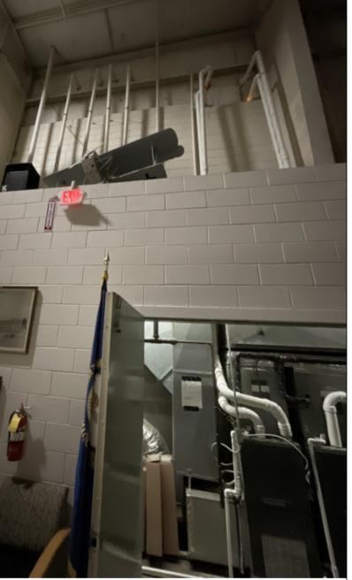
Source:CHA,2022.
3.4.3 Recommendations
It is recommended that the combustion air intake pipe and vent pipe lengths and installation are reviewed for conformance with the manufacturer’s instructions and limitations regarding maximum equivalent lengths, maximum vertical distance, and pipe fittings, to ensure adequate combustion efficiency and effective flue gas removal.
3.5 BUILDING 45 (HANGAR 45)
3.5.1 Summary
At the owner’s discretion, Building 45 was not surveyed during CHA’s visit and the assets listed in the table below were not verified in the field. The information included was provided by airport personnel prior to the site inspection and is shown for reference only.
// MASTER PLAN STUDY May, 2023 FINAL Mechanical Assessment 3-9
Figure 3-4-1 – Gas Furnace Vent Piping

HVAC-45-1
Table
3-5-1 –Building 45 Asset Registry
SplitSystem N/A Goodman 2002
HVAC-45-2 N/A N/A N/A N/A
HVAC-45-3 N/A N/A N/A N/A
HVAC-45-4
SplitSystem N/A AmericanStandard 2005
Note:N/Aindicatesinformationnotapplicableornotverifiedinfield.
Source:CHA,2022.
3.6 BUILDING 50 (ELECTRICAL VAULT)
3.6.1 Summary
The Electrical vault is a standalone building on the site which is served primarily by a 6.0 ton wall-mounted “hang on” air conditioning unit. The vestibule office has a packaged terminal air conditioner (PTAC) unit mounted on the wall which has both heating and cooling capability.
Table 3-6-1 –Building 50 Asset Registry
HVAC-50-1 Wall-MountedA/C Exterior Bard 2009
HVAC-50-2 PTAC Vestibule Trane 2009
Source:CHA,2022.
3.6.2 Inspections
During the field investigation it was noted by maintenance staff that the “hang on” wallmounted unit (HVAC-50-1) does show signs of water infiltration/leakage when the unit runs during a weather event. The PTAC heat pump (HVAC-50-2) unit casing was observed to be loose which is causing significant vibration noise when the unit fan is energized.
3.6.3 Recommendations
It is recommended that the wall-hung AC unit is inspected for proper weatherization and sealing at all openings in the exterior wall to prevent water infiltration between the unit and the wall. In addition, all condensate water shall be properly drained to the exterior per the manufacturer’s recommendations and instructions. The PTAC unit has exceeded it’s industry standard service life of 15 years and should be targeted for replacement. In the meantime, the unit casing shall be properly secured to the frame to avoid access vibration and noise during operation. Performance testing was not verified and shall be reviewed with maintenance staff due to the critical nature of the electrical vault and equipment within.
// MASTER PLAN STUDY May, 2023 FINAL Mechanical Assessment 3-10
Asset Name Description Location Make Install Year
Asset Name Description Location Make Install Year

3.7 BUILDING 51 (MAINTENANCE BLDG)
3.7.1 Summary
The maintenance building is comprised of two large maintenance bays with interior office partitions as well as a dedicated office wing. The maintenance areas are heated and ventilated by five natural gas direct-fired makeup air units located on the Mechanical mezzanine(s) coupled with roof-mounted exhaust fans. The exhaust fans were not inspected during the site visit and are not currently included in the asset registry. The office space heating and cooling demands are satisfied by two variable refrigerant flow (VRF) heat pump systems coupled with dedicated outside air units. All equipment was installed in 2015 in parallel with the building’s latest construction activities.
Table 3-7-1 –Building 51 Asset Registry
HVAC-51-1
HVAC-51-2 PackagedUnit Mezzanine Aaon
HVAC-51-3 MakeupAirUnit Mezzanine Greenheck 2015
HVAC-51-4 MakeupAirUnit Mezzanine Greenheck 2015
HVAC-51-5 MakeupAirUnit Mezzanine Greenheck 2015
HVAC-51-6 MakeupAirUnit Mezzanine Greenheck 2015
HVAC-51-7 MakeupAirUnit Mezzanine Greenheck 2015
HVAC-51-8 N/A N/A N/A N/A
HVAC-51-9 N/A N/A N/A N/A
HVAC-51-10 VRF Mezzanine Daikin 2015
HVAC-51-11 VRF Exterior Daikin 2015
HVAC-51-12 SplitSystem Mezzanine Liebert 2015
HVAC-51-13 SplitSystem Mezzanine Liebert 2015
HVAC-51-14 VRF Exterior Daikin 2015
Note:N/Aindicatesinformationnotapplicableornotverifiedinfield.
Source:CHA,2022.
3.7.2
Inspections
No deficiencies or unsatisfactory conditions were identified for the equipment verified in the field. All refrigerant piping displayed adequate and proper insulation (and jacketing as required) between indoor and outdoor units for the extents visible. Accessibility was maintained during the installation to facilitate proper maintenance of the equipment throughout the service life. Ductwork carrying conditioned air was properly insulated with fiberglass blanket, however not all supply ductwork was insulated.
// MASTER PLAN STUDY May, 2023 FINAL Mechanical Assessment 3-11
Asset Name Description Location Make Install Year
2015
PackagedUnit Mezzanine Aaon
2015

Figure 3-7-2 – Typical Makeup Air Unit

Source:CHA,2022.
Figure 3-7-2 – VRF (Outdoor Unit)


Source:CHA,2022.
// MASTER PLAN STUDY May, 2023 FINAL Mechanical Assessment 3-12

3.7.3 Recommendations
It is recommended that all supply and return air ductwork located in conditioned space carrying air at a 15 degrees Fahrenheit differential from the space ambient be insulated with minimum R-6 glass fiber insulation per latest energy codes. Jacketing is recommended in areas where exposed duct insulation may be subject to damage, but is not required. Exhaust air ductwork need not be insulated. It is recommended that baseline inspections be conducted for rooftop exhaust fans and recorded in the airports asset management software to facilitate and schedule routine maintenance/equipment checks.
3.8 BUILDING 70 (ARFF TRAINING CENTER)
3.8.1 Summary
The Airport Rescue and Fire Fighting (ARFF) facility and training center is a standalone building supported by two packaged rooftop units (RTU). Both RTU’s have natural gas heating coils and direct expansion (DX) cooling coils and appear original to the building construction (2009). A split system DX unit is located on the low roof, although the interior space components and indoor evaporator were not verified in the field.
Table 3-8-1 –Building 70 Asset Registry
HVAC-7-1 RooftopUnit Mezzanine
Carrier 2009
HVAC-7-2 RooftopUnit Mezzanine Carrier 2009
HVAC-7-3 SplitSystem LowRoof Bryant 2009 Source:CHA,2022.
3.8.2 Inspections
The exterior gas piping for both packaged units was visually inspected and exhibited severe rusting and degradation. In addition, the condensate traps for both cooling coils appeared out of compliance with typical trap depth requirements. Incorrectly installed condensate trap can result in poor fan system performance since a proper trap seal is not maintained in the drain piping.
// MASTER PLAN STUDY May, 2023 FINAL Mechanical Assessment 3-13
Asset Name Description Location Make Install Year

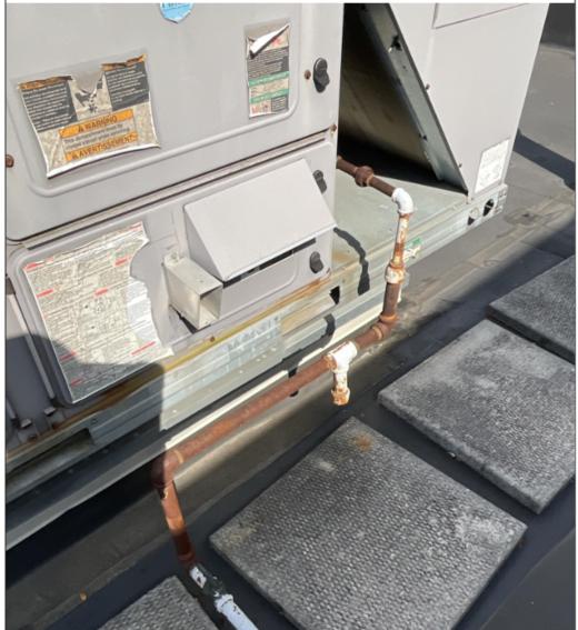
Source:CHA,2022
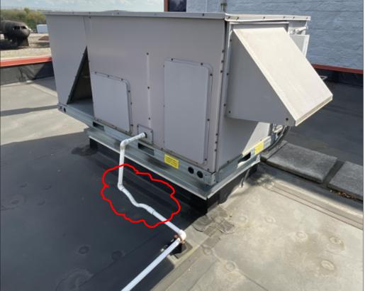
Source:CHA,2022.
// MASTER PLAN STUDY May, 2023 FINAL Mechanical Assessment 3-14
Figure 3-8-1 – RTU Gas Piping
Figure 3-8-2 – RTU Condensate Trap

3.8.3 Recommendations
It is recommended that the packaged rooftop units be reviewed for compliance with the manufacturer’s recommendations for trap depth based on fan/system static pressure ratings. Both RTU’s are within 10 years of their remaining life expectancy and shall be monitored for performance issues in the coming years prior to replacement. Gas piping shall also be considered for replacement when it comes time to replace the rooftop units. Any indoor components including air terminal boxes, coils and controls shall be verified and added to the asset management database as required.
3.9 BUILDING 109 (WESTLEX)
3.9.1 Summary
The WESTLEX facility is a standalone facility consisting of a maintenance hangar and supporting lobby/concourse with training room and break area. The concourse is served by four split system heat pumps with outdoor units located on exterior equipment pads and indoor air handlers. The indoor air handlers are located above ceiling and the equipment and associated components, and distribution devices were not verified in the field. No heating or ventilation equipment was observed in the maintenance hangar.
Table 3-9-1 – Building 109 Asset Registry
HVAC-109-4
HVAC-109-5
HVAC-109-6
Note:N/Aindicatesinformationnotverifiedinfield.
Source:CHA,2022.
3.9.2 Inspections
The condenser fan and compressor motors for HVAC-109-1 & 2 exhibited considerable vibration and noise which over time could lead to premature condenser failure.
// MASTER PLAN STUDY May, 2023 FINAL Mechanical Assessment 3-15
Asset Name Description Location Make Install Year HVAC-109-1 SplitSystem Exterior Lennox 2016 HVAC-109-2 SplitSystem Exterior Lennox 2016
SplitSystem Exterior Lennox 2016
HVAC-109-3
SplitSystem Exterior Lennox 2016
N/A N/A N/A N/A
N/A N/A N/A
N/A

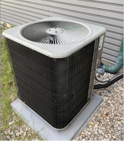
Source:CHA,2022.
3.9.3 Recommendations
It is recommended that the condenser fan and compressor motor components are properly secured per manufacturers recommendations and installation instructions. Concrete equipment pads may provide a more rigid support structure for outdoor equipment and should be considered if excess noise and vibration continue to be observed. It is further recommended that all split system indoor units are inspected and documented in the asset management software along with the outdoor units for a complete system record.
// MASTER PLAN STUDY May, 2023 FINAL Mechanical Assessment 3-16
Figure 3-9-1 – Split System (Outdoor Unit)

4 BUILDING PLUMBING ASSESSMENT
The Building Plumbing section is intended to outline the current baseline for bathroom plumbing fixtures across the site and to summarize their current condition based on the visual inspections conducted during the visit. The plumbing systems include lavatories, urinals, water closets, showers, drinking fountains and other bathroom accessories as indicated below. The assets surveyed in the list below were intended to capture each restroom group and the fixtures located within, but do not include any building level equipment such as hot water heaters, pumps and domestic backflow preventers.
4.1 BUILDING 1 (TERMINAL BUILDING)
4.1.1 Summary
Building 1’s restroom fixtures consist primarily of countertop lavatories (lavs) with automatic faucets and soap dispensers, wall-hung urinals and wall-hung water closets with automatic flush valves which were both wall recessed and top spud mounted.
Table 4-1-1 – Building 1 Asset Registry
Restroom-1-1
Restroom-1-2
Restroom-1-3
Restroom-1-4
Restroom-1-5
Restroom-1-6
Restroom-1-7
Restroom-1-8
Automaticflushvalves,sensoredfaucets WestEndLobby 1999
Automaticflushvalves,sensoredfaucets BaggageClaim 2008
Automaticflushvalves,sensoredfaucets ConcourseA 2006
Automaticflushvalves,sensoredfaucets ConcourseB (B1/2) 2008
Automaticflushvalves,sensoredfaucets ConcourseB (B3/4) 2007
Automaticflushvalves,sensoredfaucets Administration 1990
Automaticflushvalves,sensoredfaucets BoardRoom 2013
Automaticflushvalves,manualleverfaucets Checkpoint1 1975
Restroom-1-9 N/A N/A N/A
Restroom-1-10
Automaticflushvalves,sensoredfaucets, Janitorsclosetwithmopsink DeltaOperations 2007
Note:N/Aindicatesinformationnotverifiedinfield.
Source:CHA,2022.
4.1.2 Inspections
The assets noted below exhibited a visible condition that was deemed unsatisfactory on the inspection checklist and where corrective action is recommended. Sensors for flush valves and faucets were chosen at random to test overall working condition. No operational concerns were noted for the selected fixtures tested.

Restroom-1-1: Corrosion visible on lavatory drainage piping located beneath the counter.
// MASTER PLAN STUDY May, 2023 FINAL Plumbing Assessment 4-1
Asset Name Description Location Install Year


Restroom-1-2: Signs of leakage and corrosion displayed on piping beneath the fixture as well as in the base of the shroud cabinet. One of the water closet flush valve pipe connections has a loose escutcheon. There is a hole in the wall below one of the sink cabinets which was not repaired and leaves the drain piping visible within the wall.

Source:CHA,2022.
// MASTER PLAN STUDY May, 2023 FINAL Plumbing Assessment 4-2
Figure 4-1-1 – Water Damage in Shroud Cabinet


Source:CHA,2022.

Restroom-1-8: Damage visible under the Men’s side sink at the water closet wall. Fixture piping penetrations and fittings exhibit signs of wear and the wall tile has started to chip away.
// MASTER PLAN STUDY May, 2023 FINAL Plumbing Assessment 4-3
Figure 4-1-2 – Hole in Wet Wall

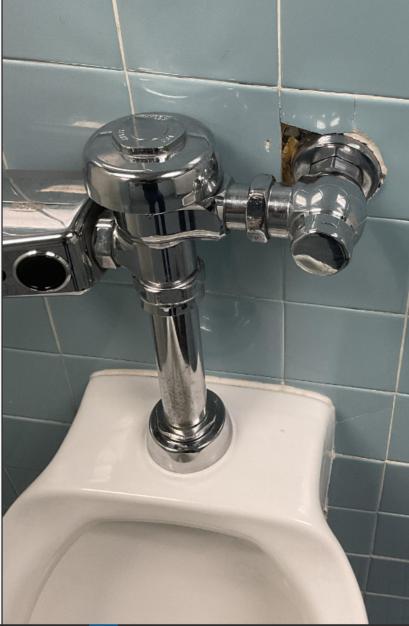
Source:CHA,2022.


Restroom-1-4: Evidence of minor water leakage through the pipe shroud is visible on the Men’s side restroom sink.
Restroom-1-5: Evidence of water leakage present at exterior of pipe shroud in the Men’s side restroom sink. Caulking and sealant around the wall-mounted water closets have given away exposing a gap between the fixture and the wall.

Restroom-1-6: Women’s sink piping is exposed along with electrical plug-in for sensored faucets. Minor pipe corrosion noted for both Men and Women’s drainage piping.
4.1.3 Recommendations
It is recommended that in all cases of leakage and water damage that all piping and joints be evaluated for watertight seal. All plumbing pipe penetrations through the restroom wall shall be properly sealed using pipe escutcheons and sealant as required. Piping underneath sinks is recommended to be evaluated for compliance with the latest Americans with Disabilities Act (ADA) requirements which may include concealing or insulating of exposed piping below the lavatories and proper mounting height of urinals and water closets. It is best practice that all
// MASTER PLAN STUDY May, 2023 FINAL Plumbing Assessment 4-4
Figure 4-1-3 – Damage to Wall Tile

electrical plug-in connection be concealed in tamperproof enclosure where accessible to public occupants. Furthermore, flush valves and faucets shall be reviewed for water savings opportunities when considered for replacement. Uniform fixture types and valves across the building is recommended for the stocking of spare parts and other maintenance considerations. It is recommended that the airport adds all critical plumbing equipment and components such as water heaters, pumps, tanks and backflow preventer assemblies to the asset register. These assets carry considerable cost value and risk if not properly maintained and routinely inspected.
4.2 BUILDING 51 (MAINTENANCE BUILDING)
4.2.1 Summary
There are three restroom groups in the Maintenance building which are summarized in the table below. The first is a single user, handicap accessible, restroom located on the office side of the building. The second group includes both Men’s and women’s shower/locker rooms and the third is a private bathroom located next to the garage bay interior offices which shares a wall with an adjacent janitors closet with a mop sink. All plumbing fixtures contain wallmounted water closets/urinals, automatic flush valves with manual overrides, countertop lavs and plug-in sensored faucets.
Table 4-2-1 –Building 51 Asset Registry
Restroom-51-1
Restroom-51-2
Restroom-51-3
Wall-mounted,automaticflushvalvewater closet,wall-mountedlavw/sensoredfaucet
Wall-mounted,automaticflushvalvefixtures, countertoplavw/sensoredfaucet
Wall-mountedwatercloset,automaticflush valve,wall-mountedlav,Janitorsclosetwith mopsink GarageBay
Source:CHA,2022.
4.2.2 Inspections
There were no unsatisfactory conditions observed during the assessment walk through and all fixtures and installations appear properly maintained.
// MASTER PLAN STUDY May, 2023 FINAL Plumbing Assessment 4-5
Asset Name Description Location Install Year
OfficeArea 2015
Showers/Lockers 2015
2015

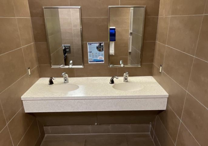
Source:CHA,2022.

Source:CHA,2022.
// MASTER PLAN STUDY May, 2023 FINAL Plumbing Assessment 4-6
Figure 4-2-1 – Typical Lavatory Installation
Figure 4-2-2 – Typical Water Closet Installation

4.2.3 Recommendations
CHA recommends no immediate action be taken for the restrooms in the Maintenance Bay given the recent installation date. Regular maintenance and care shall be considered as is standard practice for the longevity of all plumbing components and accessories in the building. Critical building level plumbing equipment such as water heaters, pumps and backflow preventers shall be added to the asset management software to facilitate and schedule routine maintenance/equipment checks.
4.3 BUILDING 57 (ARFF)
4.3.1 Summary
The ARFF building is one of the more recent construction projects on the BGA site (2020). The lower-level training room area is served by a men and women’s restroom group (Restroom-571). On the first floor, there is a single restroom outside of the office area (Restroom-57-2) and four individual toilet facilities with showers (Restroom-57-3) serving the sleeping quarters for the building. On the second floor resides a single restroom in the watch/alarm room. The type of fixtures for each space are outlined in the table below and consist primarily of wall-mounted water closets/urinals with automatic flush valves, countertop lavs in the group rooms and wallhung lavs in the single, each with plug-in, sensored faucets. There is a bi-level water cooler located in the lower level and first floor corridors.
Table 4-3-1 –Building 57 Asset Registry
Restroom-57-1
Restroom-57-2
Restroom-57-3
Restroom-57-4
Source:CHA,2022.
4.3.2 Inspections
Countertoplavswithautomaticpluginfaucets, wall-mountedurinalsandwaterclosetswith automaticflushvalves,bi-levelwatercooler
Wall-mountedurinal,wall-mountedwater closetw,automaticflushvalves,wall-mounted lavwithsensoredfaucet.
4singleswithshowers.Countertoplavswith manualgooseneckfaucet,ADAwall-mounted waterclosetswithautomaticflushvalves.
Wall-mountedurinalandwaterclosetwith sensoredautomaticflushvalves.Wall-mounted lavwithplug-inautomaticfaucet.
TrainingArea
OfficeArea
SecondFloor
Watch/Alarm Room
There were no unsatisfactory conditions observed during the assessment walk through and all fixtures and installations appear properly and adequately maintained. All wall-hung lavatory drainage piping was observed to be trapped and insulated as required.
// MASTER PLAN STUDY May, 2023 FINAL Plumbing Assessment 4-7
Asset Name Description Location Install Year
2020
2020
2020
2020

4-3-1 – Typical Lavatory Installation

Source:CHA,2022.
4-2-2 – Bi-Level Water Cooler
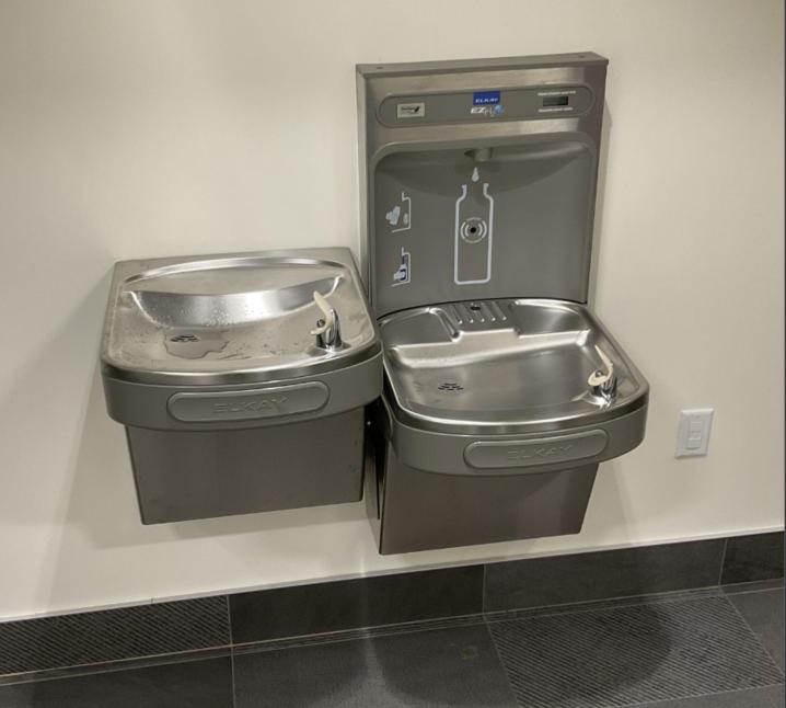
Source:CHA,2022.
// MASTER PLAN STUDY May, 2023 FINAL Plumbing Assessment 4-8
Figure
Figure

4.3.3
Recommendations
CHA recommends no immediate action be required for the restrooms in the ARFF facility given the recent installation date. Regular maintenance and care shall be considered as is standard practice for the longevity of all plumbing components and accessories in the building.
Critical building level plumbing equipment such as water heaters, pumps and backflow preventers shall be added to the asset management software along with conducting baseline condition assessments to track equipment functionality and life expectancy over time.
// MASTER PLAN STUDY May, 2023 FINAL Plumbing Assessment 4-9

5 FIRE PROTECTION ASSESSMENT
The fire protection assessments conducted during the site visit was targeted around capturing a baseline assessment of the main fire suppression components in the buildings listed below for the purposes of record keeping and maintenance logging through the airport’s asset management software (Aerosimple). The assets in this section include double check detector assemblies (DCDA), sprinkler risers, and control valves. This section focuses on those assets across the Terminal building (Building 1), Maintenance building (Building 51) and ARFF building (Building 57) as determined based on priority and onsite discussions with the owner.
5.1 BUILDING 1 (TERMINAL BUILDING)
5.1.1 Summary
The main terminal building’s fire service entrance was originally installed in the 1980’s with various renovations and additions up to present day. One of the main service entrances is located in Boiler room 2 and consists of a 4” double check detector assembly with risers and valves serving 3 control zones. There is an 8” wet-pipe riser located in the storage room of the Baggage Handling Services (BHS) area which is original to the building construction and splits to a second 4” wet-pipe riser, each with associated control valves. A dry-pipe riser valve located in the BHS corridor serves the outdoor baggage handling canopy area.
Table 5-1-1 – Building 1 Asset Registry
SprinklerSystem-1-1 N/A ConcourseB 2007
SprinklerSystem-1-2 N/A ConcourseB&C(Corridor) 2008
SprinklerSystem-1-3 N/A ConcourseA(FirstFloor) 2008
SprinklerSystem-1-4 N/A Concourse(SecondFloor) 2006
SprinklerSystem-1-5 N/A Checkpoint1&2 2008
SprinklerSystem-1-6 N/A PublicLobby 2010
SprinklerSystem-1-7 N/A AdminRenovation 2013
SprinklerSystem-1-8 N/A TSAAdminOfficeArea 1990
SprinklerSystem-1-9 N/A TheClub 2005
SprinklerSystem-1-10 N/A TSAEDSRoom 1990
SprinklerSystem-1-11 N/A TSABreakRoom 1990
SprinklerSystem-1-12 N/A TSAComp.ResourceCenter 1990
SprinklerSystem-1-13 N/A BGAOperations 1990
SprinklerSystem-1-14 Drypiperiservalve BHSCorridor N/A
SprinklerSystem-1-15 8”wet-piperiservalve BHS N/A
SprinklerSystem-1-16 4”wet-piperiservalve BHS N/A
SprinklerSystem-1-17 MainDCDAandriservalves BoilerRoom2 N/A
Note:N/Aindicatesinformationnotapplicableornotverifiedinfield.
Source:CHA,2022.
// MASTER PLAN STUDY May, 2023 FINAL Fire Protection Assessment 5-1
Asset Name Description Location Install Year


// MASTER PLAN STUDY May, 2023 FINAL Fire Protection Assessment 5-2
Figure 5-1-1 – Dry Pipe Riser Valve
Source:CHA,2022.
Figure 5-1-2 – Wet Pipe Riser Valve
Source:CHA,2022.


Source:CHA,2022.
5.1.2 Inspections & Recommendations
All sprinkler piping and components shall be monitored, inspected, and tested in accordance with local codes. Any failed testing procedure or inspection shall be rectified immediately by the owner and retested for system compliance as required.
5.2 BUILDING 51 (MAINTENANCE BLDG)
5.2.1 Summary
The maintenance building fire service entrance is fed from a 4” underground water service thru the floor and splits to cover the Electrical shop and warehouse wet-pipe sprinkler systems. Each control riser has a supervisory outside stem and yoke gate valve, supervisory switch and water flow/indicator switch for connection to the fire alarm.
// MASTER PLAN STUDY May, 2023 FINAL Fire Protection Assessment 5-3
Figure 5-1-3 – Building Double Check Detector Assembly

Asset
SprinklerSystem-51-1
Source:CHA,2022.
Table 5-2-2 –Building 51 Asset Registry
Electricalshop&warehouse systemcontrolvalves Water/SprinklerRoom 2015

Source:CHA,2022.
5.2.2 Inspections & Recommendations
No unsatisfactory conditions were observed during the visual inspection walk-through although no field performance testing was conducted. Regular testing schedules as required by the AHJ and the results of those tests shall be considered for inclusion in the asset management software for record.
5.3 BUILDING 57 (ARFF)
5.3.1 Summary
The ARFF facility is protected by a wet pipe sprinkler system with main riser located in the lower level and fed from the site water loop. The service entrance captured in the figure below consists of a stainless steel double check detector assembly with two rising stem and yoke
// MASTER PLAN STUDY May, 2023 FINAL Fire Protection Assessment 5-4
Location Install Year
Name Description
Figure 5-2-1 – Control Valves

shutoff valves and tamper switch connected to the building fire alarm system. The system and components are part of the recent building construction (2020) with no unsatisfactory workmanship observed.
Table
5-3-3 –Building 57 Asset Registry
Asset Name
SprinklerSystem-57-1
Source:CHA,2022.
Doublecheckdetectorassembly MechRoom 2020

Source:CHA,2022.
5.3.2
Inspections & Recommendations
It was witnessed that one of the inspection tags indicated a failed performance test for the DCDA which was conducted on 9/7/22 by Johnson Controls. It is recommended that corrective action be taken to resolve the field test issues and conduct retest in accordance with the local authority having jurisdiction. Refer to the relevant inspection report for Sprinkler-System-57-1 for more information.
// MASTER PLAN STUDY May, 2023 FINAL Fire Protection Assessment 5-5
Description Location Install Year
Figure 5-3-1 – Building DCDA

6 ELECTRICAL ASSESSMENT
CHA conducted a site survey of LEX from September 20th to September 22nd, 2022, with the intent of collecting information on and cataloging the facility’s assets and their condition using the software Aerosimple. For the electrical portion of this survey, under the advisement of representatives of the client, this information was taken as three separate categories as follows: Generators, Electric Rooms, and Airfield Lighting. In coordination with these representatives, the surveying of all individual airfield lighting fixtures was not undertaken at the time of this assessment due to the large quantity of fixtures, the length of time required to survey them all and the impact such a survey would have upon airport operations; instead a select handful were surveyed with maintenance personnel present to demonstrate the methods used to catalog these assets, such that these personnel would be able to survey them along a timeline more suitable to the facility. The remaining assets, categorized as Generators and Electric Rooms by building, are described in sections below.
6.1 BUILDING 1 (TERMINAL BUILDING)
6.1.1 Summary
Building 1 serves as the primary terminal building for the airport and as such is home to a plurality of the airport’s electrical assets. The assets of Building 1 can be separated into three main groups based on age: those original to the 1974 electrical renovation, those dated to approximately 1990, and those dated more recently than 1990. Unless otherwise noted, these pieces of equipment have been overall well-maintained and are in good condition. The primary points of issue that were identified during CHA’s inspections are as follows:
• The electrical equipment dated to 1974 is approaching the end of its serviceable life and should be replaced soon.
• Upon discussion with maintenance personnel, a number of switchgear assets were identified as not being regularly tested or exercised. This approach forms a nonpreventative style of maintenance and, in conjunction with the age of some of these assets, can definitely increase the likelihood of unexpected equipment failure.
Table 6-1-1 – Building 1 Asset Registry
// MASTER PLAN STUDY May, 2023 FINAL Electrical Assessment 6-1
Asset Name Description Make Install Year ElectricRoom-1-1 ElectricRoom GeneralElectric 1974 ElectricRoom-1-2 ElectricRoom GeneralElectric 1974 ElectricRoom-1-3 ElectricRoom GeneralElectric 1974 ElectricRoom-1-4 ElectricRoom SquareD 1990 ElectricRoom-1-5 ElectricRoom SquareD 1990 ElectricRoom-1-6 ElectricRoom Eaton 2019 ElectricRoom-1-7 ElectricRoom SquareD 1990 ElectricRoom-1-8 ElectricRoom Eaton 2006 ElectricRoom-1-9 ElectricRoom Eaton N/A

Generator-1-1
Generator-1-2
Generator-1-3
Source:CHA,2022
Generator Caterpillar 2016
Generator Whayne 1989
Generator Cummins 2007
Note:N/Aindicatesinformationnotverifiedinfield.
The list above includes the systems and assets highlighted to the inspection team ahead of the site visit and is not intended to serve as an all-inclusive list of Electrical assets for the terminal building. For manufacturer model number and like information, please refer to the airport’s asset data registry listed under asset details.
6.1.2 Inspection Notes
Given the scope of the survey and the need for its expediency, the assets listed in Table 6-1-1 were only surveyed visually in search of any signs of degradation or deficiency. The following assets displayed condition less than satisfactory or deficiencies that shall be further evaluated by the building maintenance and engineering teams to determine if corrective action(s) are required. The remaining assets listed in Table 6-1-1 did not display any notable visual deficiency in appearance, reliability, or function.

Electric Room 1-1: The equipment within this electric room is dated to 1974 and noted to not be regularly exercised. This asset is approaching the end of its serviceable life and should be replaced in the near future, particularly as the lack of preventative maintenance may have exacerbated any equipment deterioration.
// MASTER PLAN STUDY May, 2023 FINAL Electrical Assessment 6-2

6-1-1 – Electric Room 1-1 Switchgear

Source:CHA,2022
Figure 6-1-2 – Electric Room 1-1 MCC

Source:CHA,2022
// MASTER PLAN STUDY May, 2023 FINAL Electrical Assessment 6-3
Figure

6-1-3 – Electric Room 1-1 Switchgear

Source:CHA,2022
Figure 6-1-4 – Electric Room 1-1 Service Disconnect

Source:CHA,2022
// MASTER PLAN STUDY May, 2023 FINAL Electrical Assessment 6-4
Figure


Electric Room 1-2: The equipment within this electric room is dated to 1974 and noted to not be regularly exercised. This asset is approaching the end of its serviceable life and should be replaced in the near future, particularly as the lack of preventative maintenance may have exacerbated any equipment deterioration. As an additional note, a number of ceiling tiles were damaged at the time of inspection, leaving an unsightly aesthetic.
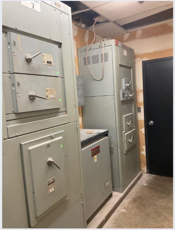
Source:CHA,2022
// MASTER PLAN STUDY May, 2023 FINAL Electrical Assessment 6-5
Figure 6-1-5 – Electric Room 1-2 Switchgear

6-6 – Electric Room 1-2 Alternative View – Source: Ryan Wright – CHA

Source:CHA,2022
Figure 6-1-7 – Electric Room 1-2 Ceiling Tiles

Source:CHA,2022
// MASTER PLAN STUDY May, 2023 FINAL Electrical Assessment 6-6
Figure


Electric Room 1-3: The equipment within this electric room is dated to 1974 and noted to not be regularly exercised. This asset is approaching the end of its serviceable life and should be replaced in the near future, particularly as the lack of preventative maintenance may have exacerbated any equipment deterioration.

Source:CHA,2022

Generator 1-2: This asset is dated to 1989 and was noted by maintenance staff as unreliable and prone to issues. Upon inspection, it was noted that there were signs of recent leakage with an oil-pickup bag present at the asset. Due to the reported unreliability of the asset and the proximity to the end of its effective lifespan, replacement of this generator is recommended in the near future.
// MASTER PLAN STUDY May, 2023 FINAL Electrical Assessment 6-7
Figure 6-1-8 – Electric Room 1-3 Equipment


Source:CHA,2022
6.1.3 Recommendations
For each asset listed above, CHA recommends the replacement of the asset in the near future. The primary concern for this building would be the pieces of electrical distribution equipment dated to 1974 as they are rapidly approaching the end of their serviceable life. As noted in the previous section, these assets were reported as not being regularly exercised, which increases the likelihood of equipment failure. The remaining asset detailed was Generator 1-2, which was reported as consistently unreliable by maintenance staff and should also be replaced.
6.2 BUILDING 2 (PARKING GARAGE)
6.2.1 Summary
Building 2 is the primary parking area for the airport terminal and is supported by an electrical room on its first floor and an exterior backup generator.
// MASTER PLAN STUDY May, 2023 FINAL Electrical Assessment 6-8
Figure 6-1-9 – Generator 1-2

Asset
ElectricRoom 2-1
Table 6-2-1 –Building 2 Asset Registry
ElectricRoom SquareD 2018
Generator2-1 Generator Cummins 1999
Source:CHA,2022
Note:N/Aindicatesequipmenttagmissing,unabletoverifyinfield.
6.2.2 Inspections
Overall, the electrical equipment present with this building has been well-maintained and is in good condition. The electrical panels in Electric Room 2-1 are nearly new and do not require anything more than regular maintenance. Generator 2-1 is over 20 years old and is approaching the end of its serviceable life, additionally, recent oil leak stains were noted within the enclosure. Despite these observations, the generator’s condition appears quite good, and no performance issues were noted by maintenance staff. Pictures of both the generator’s interior (with aforementioned oil noted) and exterior are shown below:
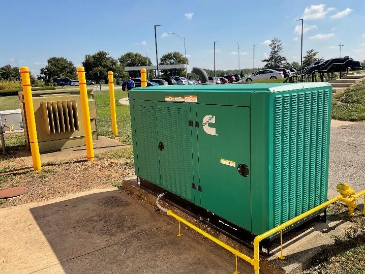
// MASTER PLAN STUDY May, 2023 FINAL Electrical Assessment 6-9
Name Description Make Install Year
Figure 6-2-1 – Generator 2-1 Exterior
Source:CHA,2022


Source:CHA,2022
6.2.3 Recommendations
As noted above, CHA does not recommend any replacements of the equipment in Electrical Room 2-1. Eventual replacement of Generator 2-1 is recommended due to its age; however, given the observations noted in the previous section, such a replacement should not be an immediate priority unless this asset presents failures or performance issues.
6.3 BUILDING 4 (RADIO SUPPORT)
6.3.1 Summary
Building 4 (Radio Support) receives emergency power from backup Generator 4-1 which is located exterior to the main beacon tower.
Table 63-1 –Building 4 Asset Registry
Source:CHA,2022
Note:N/Aindicatesequipmenttagmissing,unabletoverifyinfield.
// MASTER PLAN STUDY May, 2023 FINAL Electrical Assessment 6-10
Figure 6-2-2– Generator 2-1 Interior
Asset Name Description Make Install Year
Generator4-1 Generator Olympian 2013

6.3.2
Inspections
Overall, Generator 4-1 appears functional but shows signs of age and is weathered due to its age and exterior placement. Upon inspection and discussions with maintenance staff, all noted issues appear to be aesthetic and do not appear to impact the performance of the asset. Pictures of the asset’s exterior and interior are shown below:
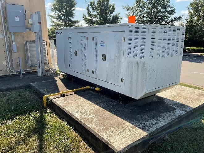
Source:CHA,2022
// MASTER PLAN STUDY May, 2023 FINAL Electrical Assessment 6-11
Figure 6-3-1 – Generator 4-1 Exterior


Source:CHA,2022
6.3.3 Recommendations
Given the lack of observed or reported degradation of the asset, CHA has no recommendations for Generator 4-1.
6.4 BUILDING 5 (RENTAL CAR FACILITY)
6.4.1 Summary
Building 5 is the airport rental car facility and is supported by several wall-mounted panelboards on the building exterior.
Table 64-1 – Building 5 Asset Registry
ElectricRoom 5-1
6.4.2 Inspections
ElectricRoom SquareD 2013
Source:CHA,2022
Note:N/Aindicatesequipmenttagmissing,unabletoverifyinfield.
The panelboards and transformer present along the exterior wall that make up Electric Room 51 are generally well-maintained and in good condition. Upon inspection, the panels were unlocked and able to be observed, which given the public access afforded by the location of these assets, should be corrected.
// MASTER PLAN STUDY May, 2023 FINAL Electrical Assessment 6-12
Figure 6-3-2 – Generator 4-1 Interior
Asset Name Description Make Install Year

Figure 6-4-1 – Electric Room 5-1 Overall

Source:CHA,2022
6.4.3 Recommendations
Given the observations noted in the section above, the assets of Electric Room 5-1 do not require replacement. CHA’s recommendation instead concerns general safety as these panels should be properly locked and secured such that only maintenance staff are able to access them.
6.5 BUILDING 13 (MUSEUM)
6.5.1 Summary
Building 13 (Museum) is supported by the electrical room within an interior closet of the building.
Table 65-1 – Building 13 Asset Registry
Source:CHA,2022
Note:N/Aindicatesequipmenttagmissing,unabletoverifyinfield.
6.5.2 Inspections
The electric room contains three panelboards that handle the building’s electrical loads. All three are in good condition and well-maintained, none present any visible issues nor any deficiencies were reported by maintenance staff. Pictures of this equipment are shown below:
// MASTER PLAN STUDY May, 2023 FINAL Electrical Assessment 6-13
Asset Name Description Make Install Year ElectricRoom 13-1 ElectricRoom N/A 1989

Figure 6-5-1 – Electric Room 13-1 Overall

Source:CHA,2022
6.5.3 Recommendations
Given the observations noted in the section above, CHA has no recommendations for replacement of the equipment in Electric Room 13-1.
6.6 BUILDING 15 (HANGAR 15)
6.6.1 Summary
Building 15 (Thoroughbred Hangar) is supplied by a pair of panels located within an internal electrical closet. The loads required by this building are fairly minimal and the equipment appears to be sufficient to properly handle these requirements.
Table 66-1 – Building 15 Asset Registry
Source:CHA,2022
Note:N/Aindicatesequipmenttagmissing,unabletoverifyinfield.
// MASTER PLAN STUDY May, 2023 FINAL Electrical Assessment 6-14
Asset Name Description Make Install Year ElectricRoom 15-1 ElectricRoom N/A N/A

6.6.2 Inspections
During inspection of the assets, no issues were encountered with the equipment within Electric Room 15-1. The only issue found with the room was that the lights within the closet are nonfunctional, requiring a flashlight to complete the inspection. Pictures of the panels are shown below:

// MASTER PLAN STUDY May, 2023 FINAL Electrical Assessment 6-15
Figure 2-16 – Electric Room 6-6-1 Panel Interior
Source:CHA,2022

6-6-2 – Electric Room 15-1 Panels

Source:CHA,2022
6.6.3 Recommendations
Given the observations noted in the section above, CHA has no recommendations for replacement of the equipment in Electric Room 15-1. The observed light fixture failure impedes any required access or maintenance of this equipment and thus its repair or replacement is recommended.
6.7 BUILDING 16 (HANGAR 16)
6.7.1 Summary
Building 16 (TacAir and Thoroughbred Hangar) is an aircraft hangar supported by a main electrical panel, located along an interior wall within the main hangar space. This panel has been classified as Electric Room 16-1.
// MASTER PLAN STUDY May, 2023 FINAL Electrical Assessment 6-16
Figure

Table 6-7-1 – Building 16 Asset Registry
Asset Name Description Make Install Year
ElectricRoom 16-1
Source:CHA,2022
ElectricRoom SquareD 2021
Note:N/Aindicatesequipmenttagmissing,unabletoverifyinfield.
6.7.2 Inspections
During the inspection, no issues were found with the functionality of the equipment. Given the nearly new state of the equipment, this is not surprising. However, the area in front of the panel was obstructed, thus not conforming with the three-foot clearance requirements for the panel.

Source:CHA,2022
6.7.3 Recommendations
Given the observations noted in the section above, CHA has no recommendations for replacement of the equipment in Electric Room 16-1. It is instead recommended to clear the area in front of the panel to ensure proper clearance of electrical equipment in maintained.
// MASTER PLAN STUDY May, 2023 FINAL Electrical Assessment 6-17
Figure 6-7-1 – Electric Room 16-1 with Panel Interior Shown

6.8 BUILDING 45 (HANGAR 45)
6.8.1 Summary
Building 45 (Hangar 45) is an aircraft hangar whose power is supplied by two wall-mounted electrical panels located within an interior restroom of the hangar. This room has been classified as Electric Room 45-1.
Table 68-1 –Building 45 Asset Registry
ElectricRoom 45-1
Source:CHA,2022
SquareD N/A
Note:N/Aindicatesequipmenttagmissing,unabletoverifyinfield.
6.8.2 Inspections
The electrical equipment in Electric Room 45-1 appeared to be in good condition upon inspection, with no visible issues to note in terms of the equipment’s performance. However, the location of this equipment within a restroom has ensured that access to these panels is difficult and at the time of inspection the three-foot clearance in front of the panel was not maintained. The presence of a sink, toilet, and shower in close proximity to these panels means that this equipment will likely have moisture issues as time goes on.
Figure 6-8-1 – Electric Room 45-1

Source:CHA,2022
// MASTER PLAN STUDY May, 2023 FINAL Electrical Assessment 6-18
Asset Name Description Make Install Year
ElectricRoom

6.8.3 Recommendations
The unique location of the electrical panels of this asset, inside of a restroom, means that the majority of the observed issues in the previous section cannot be resolved as long as the asset is retained within the restroom. CHA would recommend relocating this electrical equipment to another area that does not pose any moisture issues. In the meantime, the current recommendation of what can be done to improve the asset while keeping it in its current location would be to move as much as can be moved out of the area immediately in front of the panels to ensure proper clearance.
6.9 BUILDING 50 (ELECTRICAL VAULT)
6.9.1 Summary
Building 50 is the Airfield Electrical Vault and contains Electric Room 50-1 which has the equipment to support the airfield electrical loads. These are backed up by the exterior backup Generator 50-1.
Table 69-1 – Building 50 Asset Registry
Source:CHA,2022
Note:N/Aindicatesequipmenttagmissing,unabletoverifyinfield.
6.9.2 Inspections
Upon inspection, the electrical equipment within the vault (designated Electric Room 50-1) appears to be clean, well-maintained, and fully functional. The only observed issue present within the Electric Room is that the rolling shelves present within the room violated the threefoot clearance requirements in front of the switchgear. As for Generator 50-1, located exterior to the electrical vault, minor age, wear, and dust are present both inside and outside of the generator enclosure. These are to be expected with the age of the generator. There were no issues observed or reported by maintenance staff concerning the performance of the asset.
// MASTER PLAN STUDY May, 2023 FINAL Electrical Assessment 6-19
Asset Name Description Make Install Year Generator50-1 Generator Kohler 2010 ElectricRoom 50-1 ElectricRoom SquareD 2010

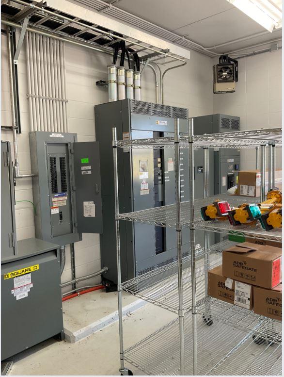
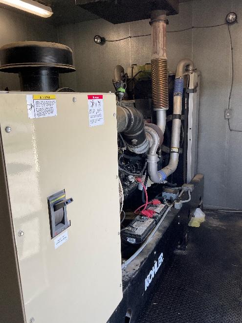
// MASTER PLAN STUDY May, 2023 FINAL Electrical Assessment 6-20
Figure 6-9-1 – Electric Room 50-1
Source:CHA,2022
Figure 6-9-2 – Electric Room 50-1 Interior
Source:CHA,2022

Figure 6-9-3 – Generator 50-1 Exterior

Source:CHA,2022
6.9.3 Recommendations
Given the lack of observed or reported deficiencies with the assets of Building 50-1, no replacements are recommended by CHA at this time. CHA would recommend the rearrangement of the rolling shelves present within the building to allow proper clearance in front of the switchgear of Electric Room 50-1.
6.10 BUILDING 51 (MAINTENANCE BLDG)
6.10.1 Summary
Building 51 is a large vehicle maintenance building that serves the airport’s mechanical needs. Its electrical loads are supported by three electrical rooms located within the building and it receives emergency power from the backup Generator 51-1, located exterior to the main building. All of these assets are original to the same electrical project from 2015.
Table 6-10-1 – Building 51 Asset Registry
Source:CHA,2022
Note:N/Aindicatesequipmenttagmissing,unabletoverifyinfield.
// MASTER PLAN STUDY May, 2023 FINAL Electrical Assessment 6-21
Asset Name Description Make Install Year Generator51-1 Generator OnsiteEnergy 2015 ElectricRoom 51-1 ElectricRoom Eaton 2015 ElectricRoom 51-2 ElectricRoom Eaton 2015 ElectricRoom 51-3 ElectricRoom Eaton 2015

6.10.2 Inspections
Upon inspection, the Electric Rooms of Building 51 presented no visible issues and had no issues reported by maintenance staff. The equipment located there is all in excellent condition, dated to 2015, and fully functional. Generator 51-1 was generally in good condition at the time of inspection, however there were signs of minor leakage present within the generator enclosure as shown below:

Source:CHA,2022
6.10.3 Recommendations
As noted above, there were no observed deficiencies with the assets within Building 51 and thus CHA has no recommendations for these electrical assets. As for Generator 51-1, the cause of the minor leakage could not be determined upon this inspection. CHA recommends further investigation of this asset to determine the best course of action.
6.11 BUILDING 57 (ARFF)
Building 57, the ARFF building, has its loads supported by equipment located in the interior Electric Room 57-1 and backed up by emergency Generator 57-1.
// MASTER PLAN STUDY May, 2023 FINAL Electrical Assessment 6-22
Figure 6-10-1 – Generator 51-1 Interior

Table 6-10-1 – Building 51 Asset Registry
Generator57-1
ElectricRoom57-1
Source:CHA,2022
Note:N/Aindicatesequipmenttagmissing,unabletoverifyinfield.
6.11.1 Inspections
Upon inspection, the equipment in the Electric Room 57-1 appears to be in excellent condition, with no performance issues visible or reported by maintenance staff. Generator 57-1 is in a similarly good condition; both assets were dated to 2020 and appear to be nearly new as that install date would suggest.
6.11.2 Recommendations
Given the excellent condition of both electrical assets noted in the sections above, CHA has no recommendations for these assets at this time.
6.12 BUILDING 70 (ARFF TRAINING CENTER)
Building 70, the ARFF Training Center, is designed to enhance firefighter training with simulated plane fires. This facility has its loads served by a singular electrical room present within the building (designated Electric Room 70-1).
Table 6-12-1 – Building 70 Asset Registry
Source:CHA,2022
Note:N/Aindicatesequipmenttagmissing,unabletoverifyinfield.
6.12.1 Inspections
Upon inspection, the electrical equipment was dated to 1997 and was noted by maintenance personnel present to not have any outstanding performance issues. While the equipment is beginning to show its age, it does not appear to have any effect on the equipment’s capabilities.
// MASTER PLAN STUDY May, 2023 FINAL Electrical Assessment 6-23
Asset Name Description Make Install Year
Generator Kohler 2020
ElectricRoom SquareD 2020
Asset Name Description Make Install Year
ElectricRoom Eaton 1997
ElectricRoom70-1

Figure 6-12-1 – Electric Room 70-1 Equipment

Source:CHA,2022
Figure 6-12-2 – Electric Room 70-1 Entrance

Source:CHA,2022
// MASTER PLAN STUDY May, 2023 FINAL Electrical Assessment 6-24

Figure 6-12-3 – Electric Room 70-1 Main Distribution Panel Interior

Source:CHA,2022
6.12.2 Recommendations
As noted above, the electrical equipment in Electric Room 70-1 is beginning to show its age but with continued proper care and maintenance it should not require replacement for some time. As such, CHA does not have recommendations for the replacement of any electrical equipment at Building 70.
6.13 BUILDING 109 (WESTLEX)
Building 109, referred to as Westlex, is a series of smaller private aircraft hangars whose electrical needs are supported by 2 Electric Rooms in the primary hangar and office building.
Table 613-1 – Building 109 Asset Registry
Source:CHA,2022
Note:N/Aindicatesequipmenttagmissing,unabletoverifyinfield.
// MASTER PLAN STUDY May, 2023 FINAL Electrical Assessment 6-25
Asset Name Description Make Install Year ElectricRoom 109-1 ElectricRoom SquareD N/A ElectricRoom 109-2 ElectricRoom SquareD 2018

6.13.1 Inspections
Upon inspection, the Electric Rooms are in good condition and appear to be well-maintained, with no issues reported by maintenance staff. Electric Room 109-1 contains the main switchgear for the Westlex facility and Electric Room 109-2 contains two recessed, wallmounted panels that provide power to the primary hangar and office building.
6.13.2 Recommendations
As noted above, the electrical assets of Building 109 are in good condition and do not require replacement at this time. As such, CHA has no recommendations for these assets.
// MASTER PLAN STUDY May, 2023 FINAL Electrical Assessment 6-26

APPENDIX A (BUILDINGS MAP)
// MASTER PLAN STUDY May, 2023 FINAL i

APPENDIX
B
(TERMINAL ROOF MAP)
// MASTER PLAN STUDY May, 2023 FINAL ii

APPENDIX C (ASHRAE EQUIPMENT LIFE EXPECTANCY CHART)


// MASTER PLAN STUDY May, 2023 FINAL iii


