MODULAR INSTALLATION MANUAL
RESIDENTIAL MODULAR INSTALLATION MANUAL RANCH STYLE HOME



RESIDENTIAL MODULAR INSTALLATION MANUAL RANCH STYLE HOME


This manual contains important information for the setting and installation of the specified modular home. Please read all instructions and documentation that apply to the specific home prior to commencing site work or installation.
The builder is expected to have an understanding and experience in conventional site built construction of homes. This manual does not cover every aspect of home building and construction, it highlights the differences in modular construction and the major requirements for builders to follow in order to properly install the home.
This manual is designed for the installation of multi‐section ranch style homes based on prescriptive code parameters unless otherwise noted. For multi‐story and Cape Cod homes or items not covered in this manual, contact the manufacturing facility for additional details.
No manual can cover all circumstances that may exist for a specific home design or building site. For questions or further clarification please contact the manufacturer, a registered engineer, registered architect, and/or your local building official.
It is the responsibility of the builder to ensure that the final installed product meets or exceeds all local codes.
The builder is responsible for all on‐site permits, inspections, and scheduling of all sub‐contractors prior to the setting of the home. Champion, under no circumstance, will be held responsible for any action taken on‐site. The builder shall ensure that all work is completed in a professional manner, and shall conform to all local building codes. It shall be the builder’s responsibility to meet state requirements, if any, for having a licensed builder or construction official present during setting of the home.
There are potential hazards associated with the installation of a modular home. Home installers are licensed, and as experienced professionals, should recognize these hazards, be qualified to work with them, and be capable of providing safe work practices and equipment that minimize the risks of injury.
Only qualified persons should install a modular home. As qualified professionals in the field of modular home installation, installers are the experts and must be aware of the hazards and conditions specific to each project.
Construction crews should be trained in the skills required and be supervised by experienced personnel. Installers should regularly inspect work performed by crews and subcontractors.
Please reference the data plate for the following design specifications:

Roof Snow Load Floor Live Load Wind Speed Seismic Design Category Applicable Code(s)
Data plate location varies per state requirements. It is the responsibility of the builder to ensure that the home is not set in a location where the site design requirements exceed the design specifications.
UNLESS OTHERWISE SPECIFIED, UNDER NO CIRCUMSTANCES WILL THE MANUFACTURER BE RESPONSIBLE FOR ANY OF THE FOLLOWING:
INSTALLATION/COMPLETION OF:
A. All penetrations thru floor and ceiling on all units shall be draft stopped and fire blocked per applicable code.
B. Siding at end walls and in other areas where not factory installed.
C. Ship loose items.
D. Floor Insulation, unless optioned on order.
E. Finished openings along the marriage line such as doorways, openings and archways.
F. Vent extension to the outside (dryer, fireplaces, furnaces, plumbing etc.)
G. Ridge vents and Ridge Caps.
H. On‐site Garage, foundations, porches, etc.
I. Gas Pipes, shut off valves, risers, etc.
J. Home blower door test, (if required).
A. Interior doors for proper opening and closing.
B. Exterior doors for proper opening and closing.
C. Exterior doors for proper seal.
D. Reset any loose trim or miter corners.
E. Re‐stretch any loose carpet.
F. Repair minor drywall cracks.
A. Secure breaker box if shipped loose.
B. Circuit crossover connections.
C. Supply and install the meter base and connection from the power source.
D. Perform a continuity and function test on all circuits.
E. Coordinate and provide required inspections by local authority.
A. Supply and install the shut off valve and water supply into the inlet.
B. Supply and install the water heater expansion tank and vacuum relief valve, as required.
C. Adjust any trap assemblies at tubs, showers, and sinks for proper seal and holding capability.

D. Pressure test all water supply lines before connecting water source.
E. Test all DWV lines prior to/or immediately after connecting water source
F. Extend vents in attic to outside as required by code including installed vent boots if not provided.
G. Some plumbing manifolds may require site installation per design conditions
H. Provide for inspection by local authority, if required.
I. Notching or drilling of joists is not permitted. Consult a local P.E. if needed before modifying any joists or rafters on the modular unit.
HVAC:
A. Professional Installation heating/cooling system (if shipped loose or omitted).
B. Extend vents for the furnace or water heater that are capped in attic.
C. Install the crossover duct work in attic or floor system as required.
D. Install any necessary return air duct and system.
E. Return air is sized for a factory supplied furnace. Any furnace installed on‐site is not Champion’s responsibility. See furnace instructions for return air requirements.
F. Coordinate and provide for inspections by local authority as required.
G. Factory installed furnaces are designed for the factory built portion of the home only, unless otherwise noted. DO NOT heat on‐site basements with a factory installed furnace.
H. All gas piping, shut off valves, and risers are installed on‐site by others.
I. Registers may be supplied for all homes going on conditioned crawlspace, adjust according for airflow.
J. Duct blower test, as required by code. Air leakage issues and maintenance is not Champion’s responsibility.
K. Testing and commissioning of entire system
A. Damages from transportation must be noted on driver’s sheets.
B. Shortages and defects must be reported within 3 days of delivery.
C. Interior damages must be reported prior to customer possession.
D. Cosmetics items not reported within 30 days & prior to possession will not be considered under warranty provisions.
E. Major issues must be reported immediately upon delivery & documented with photographs and/or video.

The home is designed to meet snow, wind, and seismic conditions as stated on the home’s data plate. DO NOT locate the home where site conditions exceed design parameters as outlined on the data plate. Locations with lower design loads are acceptable.
Ensure that the transportation equipment and the modules can be safely moved to the site without damage. Prepare the site as necessary to ensure a successful set by filling any holes or soft spots in the access road and make sure there is adequate space and a strong enough surface between road and the site. Consideration must be given to any berms, ditches, or soft fields that may need to be traversed. Confirm adequate vertical clearance by removing any obstacles such as overhanging branches and overhead wires. Ensure a qualified professional manages any adjustments to electrical wires or equipment. Special transportation permits may be required from the local authority having jurisdiction (LAHJ) and/or state department of transportation.
If a suggested foundation design is provided with this home, it is based on IRC prescriptive guidelines with an assumed non‐expansive soil and a minimum bearing capacity of 2,000 psf. It is the responsibility of the builder to verify that actual soil conditions fall within these design assumptions through consultation with LAHJ and/or a geotechnical engineering professional. If actual soil characteristics do not meet design criteria and if the soil is not one of the following Unified Soil Classification System types, then a separate foundation design is required specific to site conditions.
GW Well graded gravels, gravel sand mixtures, little or no fines
GP Poorly graded gravels or gravel sand mixtures, little or no fines
SW Well graded sands, gravelly sand, little or no fines
SP Poorly graded sands or gravelly sands, little or no fines

GM Silty gravels, gravel‐sand‐silt mixtures
GC Clayey gravels, gravel‐sand‐clay mixtures
SM Silty sand, sand‐silt mixtures
SM‐SC Sand‐silt‐clay mixtures
*The foundation design provided with this home is for generic reference only. Specific foundation design must consider site specific conditions and be performed by licensed engineer.
Remove all transit plastic, straps and fasteners, etc. on each module to ensure a close fit between mating walls and proper ventilation of the attic.
Install a strip of insulation or mate line gasket around the entire perimeter of one unit only at the mating wall (center) side. This line includes floor, end walls and girder beam. Additional insulation/gasket may be installed at each opening thru the marriage wall if needed to meet energy requirements.

Follow the dimensions on the foundation print supplied and work to a close tolerance. Size and square must be within 1/2” and level within 1/8”. It is better to error on the side of under sizing the foundation than oversizing the foundation. It is easier to shim out the sheathing and siding when the home hangs over the foundation than it is to fix when the foundation is larger than the home.
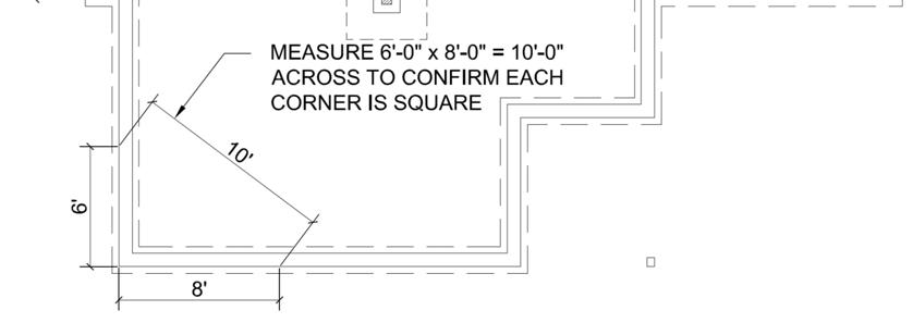

The foundation prints provided show dimensions from the out to out of studs. These dimension do not include exterior sheathing or siding. Adjustments to the foundation dimensions may be needed based on gaps incurred at the time of set or brick ledges (if any). These adjustments shall be the responsibility of the builder.


The builder shall supply and install sill plates and anchor bolts according to code. The spacing for the anchor bolts is suggested in the foundation prints provided with this home. Deviation from these requirements must be performed by a licensed engineer. Sill plate anchor bolts should not extend above the sill plate as they may interfere with the module floor rim joist or floor joists, causing damage or misalignment of floors. Flush wrap around strap anchors are more suitable. Some typical options are shown below.

Foundation drawings provided by Champion are intended to specify a suggested configuration for connecting the modular home to the foundation, provide location of footings for support columns, and provide loading magnitude. All other information is generic and must be designed by others per applicable codes and site conditions. Champion is not responsible for the foundation design required for various site or soil conditions.
If the home is intended to be located near a flood‐prone area, consult a licensed engineer to make sure the foundation design and construction conform to applicable requirements of the Local Authority Having Jurisdiction (LAHJ).
All foundation walls, piers, columns, and beam supports shall be in place prior to installing the home.

If the home is located in a high wind area or a high seismic area and no longer follows prescriptive code requirements, special shear wall foundation anchors may be required. The standard suggested shear wall anchor is a Simpson STHD14RJ or equal that is precast into a poured concrete foundation wall at specified locations. These locations are provided in the loading drawings of the home’s design package. It is the responsibility of the builder to properly locate these anchors according to foundation drawings provided or to provide an alternate design that will transfer the appropriate forces from the shear wall chords into the foundation. These designs are specific to geography and floor plan criteria and must be generated and sealed by a licensed engineer. The detail below is the recommended typical precast shear wall anchor system.


As illustrated below, move the first section of the home into position in preparation for craning onto the foundation. Ensure path of crane swing is unobstructed.


Remove all close up and shipping materials from the home.

Remove or drive flush all protruding nails, staples, or other objects that could hold the sections apart along the marriage surfaces and along the bottom of modules.
Install marriage line gasket around perimeter of marriage wall surfaces.
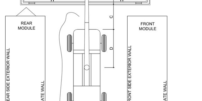
If the roof is hinged, it must be raised prior to setting the box on the foundation.


Fasten the trusses as shown below. If the home is located in a high wind area (above Vult =140 mph 3 sec. gust or Vasd = 115 mph 3 sec gust), alternate connection details are required. Consult design drawings or a licensed engineer for details.


Individual module weight varies depending on length, width, and style of home. This, along with the distance the crane has to extend to the foundation, drastically affects the size of crane needed to erect the home. Consult with a licensed crane operator to determine proper crane size required for a particular situation.

The following are suggested instructions for craning modules into position. All rigging, crane location, and lift points are the responsibility of a licensed crane operator.
Before lifting, be sure to detach module from carrier frame by removing all floor joist lags from carrier frame.


Before Lifting:
Be sure to detach module from carrier by unscrewing all floor joist lags from frame.

Check for clearance of cables or straps. If the cables or straps touch the siding or any other part of the module, block them away from the module at the appropriate locations with 2x material.

Module should be lifted at a slight angle with sidewall lower than the marriage wall. This will make it easier to position the module on the foundation.


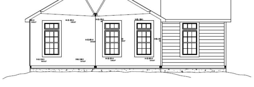


Connect properly positioned modules to the foundation per details below.


To avoid splitting rim joists predrill for all lag connections.

When lagging modules together, do not use lags to pull modules together.
Special connections for specific geographic regions as outlined on individual design packages may supersede these suggested details.


Predrill for all lag connections to avoid splitting rim joists.


Do not use lags to pull modules together.
Special connections for specific geographic regions as outlined on individual design packages may supersede these suggested details


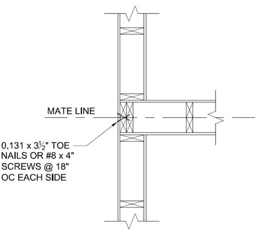
Align ceilings and end walls of each module along the inside of the home.
With the end walls aligned, fasten together with 0.131”x3 ½” toe nails spaced at a maximum of 18” on center as shown below.
Once the end walls are secured, make sure the roof and ceiling are aligned. Adjust as needed by racking the module to bring the roofs and ceilings into alignment. Secure adjoining roof sections together per details below. DO NOT USE LAGS TO PULL MODULES TOGETHER.


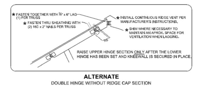
Install truss ridge cap per detail below. If the home is located in a high wind area (above Vult =140 mph 3 sec. gust or Vasd = 115 mph 3 sec gust), alternate connection details may be required. Consult design drawings for special details.
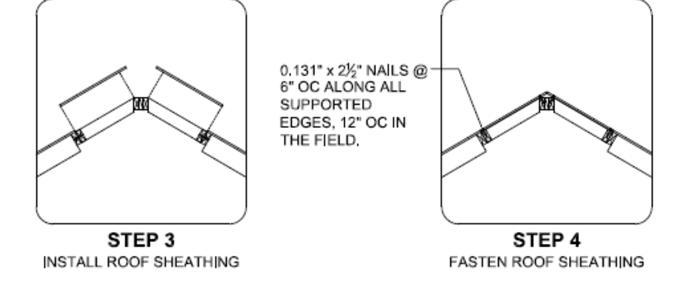


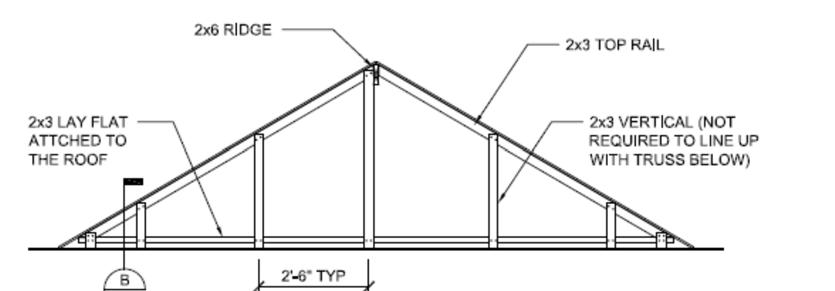
Install end wall gable framing per details below.


Fasten 2x4 filler wedge framing to end truss with 0.131” x 3” nails @ 6” o.c. Install 2x4 framing members @ 16” o.c. as shown above. Fasten OSB sheathing to filler wedge framing with 0.131” x 2 ½” nails @ 6” o.c. at panel edges and 12” o.c. in the field unless noted otherwise on design drawings for high wind or seismic applications.
All final exterior close‐up work including siding, fascia, and soffits shall be installed per manufacturer and local code requirements using shipped loose or locally sourced materials.

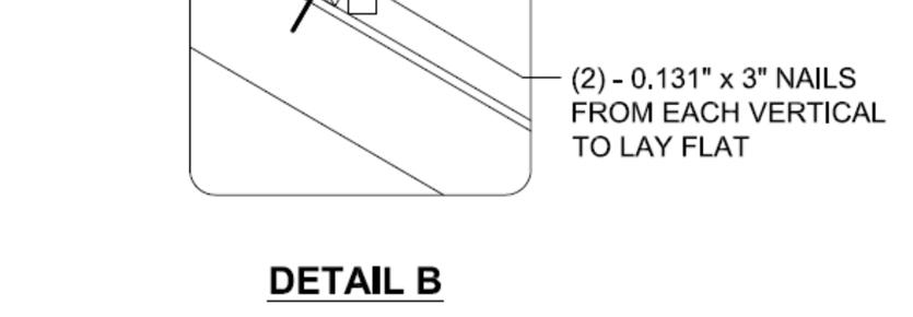
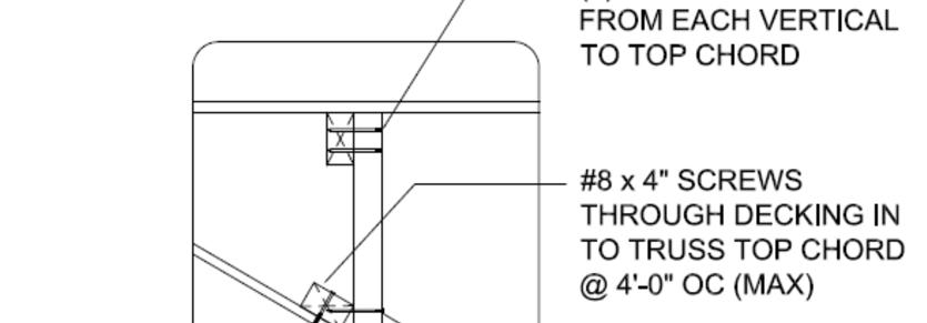
Install transitional dormers between perpendicular home sections. Materials for these areas may be shipped loose from the manufacturing facility or supplied locally. These materials are installed per IRC and design package requirements as shown below.




Only qualified personnel may install any comfort cooling system not provided with the home. Follow the manufacturer’s installation instructions and conform to local code requirements.

The home’s electrical distribution panel may contain optional factory‐installed circuits for air conditioning. The maximum full load ampere draw for the desired air conditioning unit must not exceed the actual circuit rating.
The electrical distribution panel in the home may not have been sized for the additional load of a non‐factory‐installed air conditioning unit. In such situations, a separate outside electrical supply may have to be provided. Refer to the design drawings and electrical calculations to determine if the supplied electrical panel is sufficient. Any field‐installed wiring beyond the junction box must include a fused disconnect located within sight of the condensing unit. The maximum fuse size is marked on the condenser data plate. Local codes will determine the acceptability of the air conditioning equipment, rating, location of disconnect, fuse‐type branch circuit protection, and connections to the equipment.

Fireplaces, wood stoves, and gas water heaters may require on‐site installation of combustion air inlets and on‐site installation of additional sections of approved chimney pipe and rain cap assembly. Site installations of vents shall conform to the appliance manufacturer’s installation instructions. Ensure proper permits and inspections to local codes are in place before performing such work.
The fireplace chimney shall extend at least three feet above the part of the roof through which it passes and at least two feet above the highest elevation of any part of the roof within ten feet of the chimney. See detail below.


A fireplace may be factory installed such that the firebox is in one section of a multi‐section home and the hearth in the adjacent section. In such cases, the hearth must be shipped loose with the unit and field installed in strict compliance with local authority and manufacturer’s installation instructions.
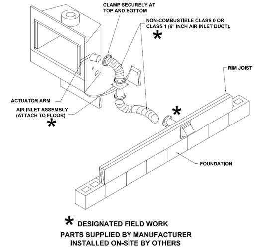
Combustion air intake ducts factory terminate just below the bottom covering of the floor and must be extended to the outside once the home has been set on foundation per fireplace manufacturer’s installation instructions. Do not allow the combustion air inlet to drop from the hearth beneath the home. Locate the inlet damper above the expected snow level.


If the home is equipped with a combination range, cook‐top/grill, or oven that contains its own exhaust system, route the exhaust so that it does not exit under the home. Connect metallic duct between the elbow protruding from the floor and the termination fitting. Support the assembly according to the manufacturer’s installation instructions.
The water system for the home has been designed for a maximum inlet pressure of 80 psi. The minimum pressure at the entrance shall be 40 psi. If the home is located where the local water supply pressure exceeds 80 psi, install a pressure‐reducing valve.

1. Remove the shipping caps from the water lines.
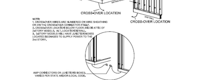
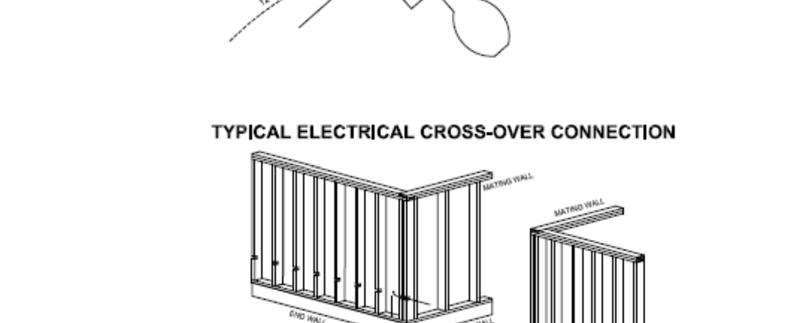
2. Install the crossover connectors provided with the home per details below.

3. Connect the main water source to the inlet located under the home.

4. Check water system for leaks per applicable code.
5. In areas subject to freezing temperatures, freeze protect exposed sections of water supply piping.
6. If required by local energy codes, insulate hot water crossovers.
All gas appliances in this home, including the heating system, are equipped for natural gas unless otherwise specified. If LP gas is to be used as the gas supply, a qualified service person must convert all appliances per the instructions provided by each appliance manufacturer.

The maximum operating pressure for gas piping in the home shall not exceed 5 psig. If gas from any supply source exceeds this pressure, a pressure reducing valve must be installed. For LPG systems, the operating pressure should not exceed 20 psig.

Special orifices and regulators are required for each kind of gas and for high altitudes. See the manufacturer’s instructions accompanying each gas‐burning appliance for required modification. Before making any connections to the site supply, check the inlet orifices of all gas appliances to ensure they are correctly set up for the type of gas to be supplied.
1. Remove the dust caps from the gas lines on the house.
2. Install the crossover connectors provided with the home as shown in the details on the next page.
3. Inspect gas appliance vents to ensure they have been properly connected to the appliance. Make sure that roof jacks are installed and have not come loose during transit.
4. Connect the gas inlet to the meter at the supply.
5. Check gas lines for leaks per applicable code.

Gas supply crossover details


DWV CROSSOVER AND COMPLETION
Drain, waste, and vent systems are plumbed and manifolded to greatest extend possible in plant. Final manifolds and plumbing to site services must be completed on site per local code requirements and design drawings,



1. Butt two ends of the main heat duct trunks together and secure with (2) two foot pieces of supplied pressure sensitive tape (UL‐181‐AP) on the top and two pieces on the bottom. Locate tape as close as possible to the duct edges as shown in figure #1.
2. Tape the butt joint with at least (2) pieces of pressure sensitive around the entire perimeter as shown in figure #1, on Page 33.
3. Repeat steps 1 & 2 as necessary until required main duct length is achieved.
4. Install main heat duct to bottom of floor system and support heat duct as shown in figure #2, on Page 33, at 4’ intervals with plastic, metal, or woven nylon strapping. See model specific duct plans for location of duct trunk.

5. Cut 13”x13” (min) square hole in top of main duct at the furnace plenum connection. Bend plenum tabs back inside of main duct and seal around the perimeter of connection with pressure sensitive heat duct tape as shown in figure #3, on Page 33.
6. Cut 6” holes in the side of main duct for flex hose connector at locations shown on model duct plans. Bend half of the connector tabs to fit inside of hole. Install connector as shown in Figure #4, on Page 33 and seal perimeter with pressure sensitive tape.
7. Slide at least 1” of flexible heat duct over register boot as shown in figure #5, on Page 33, and secure to connector with supplied tie straps.
8. Cut duct to desired length and slide the cut end of duct over connector at main heat duct. Flex duct should be fully extended to avoid excess bending or sag.
9. Cut a 12” or 14” round hole in the bottom side of main heat duct directly below the furnace and install the 12” or 14” crossover connector in the hole as shown in figure #6. Bend connector tabs to secure to main duct and seal around the connector with approved tape.
10. Repeat step #8 for the other end of the crossover duct after checking the model specific duct plans for location of connector on the other sections of home.
11. Preform duct blower test, if required by code.
AND CROSSOVER (IF SUPPLIED OR INSTALLED WITH HOME) (CONTINUED)


Find collection box.
Find how many return air grills are on non‐furnace section of home. Also see mechanical plan for layout.


Locate and remove temporary covers over flexible duct.
Pull flexible duct from non‐furnace section and cut to length.

Any structures, devices, accessories, etc. installed on‐site are not the responsibility of the home manufacturer. Design all attached buildings and structurers to be completely self‐supporting including dead, live, wind and seismic loads. All accessory structures to have proper fire separation as required by the local authority having jurisdiction (LAHJ).
A garage or carport must be self‐supported and structurally independent of the modular‐built portion of the home. All site built structures must conform to the requirements of the LAHJ. Electrical circuits in garages shall be provided with ground fault interruption.
Site‐constructed porches and decks must be self‐supporting and must be constructed and inspected per LAHJ requirements.
Steps, stairways and landings must be constructed and inspected per local authority having jurisdiction requirements.
