Inside the world of modern motorsport technology One great car, two radically different aero ToyotaassessmentsTS010HowtheC42 has shaken up F1’s status quo Alfa Romeo FUTURE FUELS Formula 1 releases first details of 2026 power unit regulations PORSCHE 992 GT3 R All-new incarnation of a racing legend INDYCAR STRATEGY Is this biggestmotorsport’schallenge? ELECTRIC forEfficiencyMOTORSgainsEVracecars UK £5.95 / US $14.50 October 2022 / Vol 32 No 10


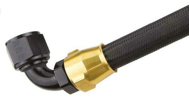
Theevolutionin FLUIDHORSEPOWER XtraordinaryHoses,Fittings&Filters ProPLUS Xtreme RaceHose ™ ProPLUS Reusable Hose ™ XRP ProPLUS RaceHose ™ Xtreme Filtration Logonto www.xrp.com anytimefor catalogdownloads, newproductupdates andtechtips. ® Likeuson Facebook/XRPinc Followuson Instagram @XRPracing UNITEDSTATES XRP,Inc.5630ImperialHighwaySouthGate,CA90280sales@xrp.comtel5628614765fax5628615503 INEUROPEANDTHEUK ProtecFuelSystemsLtd.info@protecfuelpumps.comtel+44(0)1215726533 THE XTREMEIN RACECAR PLUMBING


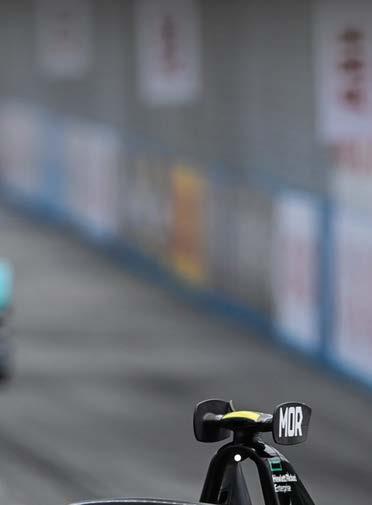
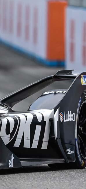
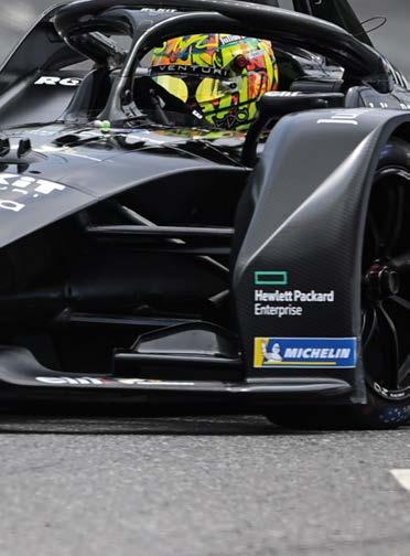
CONTENTS OCTOBER 2022 Volume 32 Number 10 Subscribe to Racecar Engineering – find the best offers online www.chelseamagazines.com/shop Contact us with your comments and views on Facebook.com/RacecarEngineering or Twitter @RacecarEngineer OCTOBER 2022 www.racecar-engineering.com 3 COVER STORY 6 Alfa Romeo C42 The tech secrets behind F1 2022’s surprise package COLUMN 5 Andrew Cotton Sustainable fuels in Formula 1 FEATURES 12 Porsche 911 GT3 RSR GT racing’s most famous car gets its 992 upgrade 20 IndyCar strategy Talking tactics with the US series’ top race engineers 30 Test sessions How to get the very best from your on-track development 38 Toyota TS010 revisited Mirroring intense 1990s wind tunnel work in modern CFD TECHNICAL 48 EV motors Electric motorsport’s efficiency drive examined 58 Additive manufacturing Critical insights into the disruptive technology of 3D printing 68 Danny Nowlan Could an electric GT3 racer be a true contender? 74 AVL and Ansible Motion Using driving simulators as testing tools BUSINESS 76 News F1 2026 engine regulations; porpoising fixes announced; Lynk & Co quit WTCR 81 Chris Aylett Looking forward to October’s Silverstone business event 82 Bump stop Venturi Racing’s Edoardo Mortara won the final race of Formula E’s season at Seoul, South Korea, in August. Turn to page 48 to learn how race-bred electric motors are getting ever more efficient LAT


TESTED & PROVEN All ARP fasteners are manufactured entirely in our own facilities in Southern California and raced all over the world. Special Orders +1.805.525.1497 • Outside the U.S.A. +1.805.339.2200 1.800.826.3045 • arp-bolts.com 5,000 catalog items and specials by request Around. Above. Below. ARP fasteners are used in racing all around the globe and applications from space to below the earth’s surface. ARP Fasteners are tested and proven in the most demanding environments on Earth...and beyond.


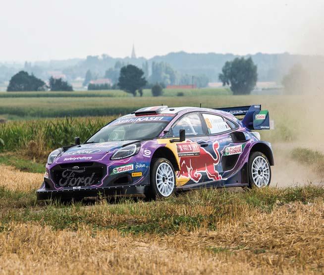
Biofuels are already being used in many international motorsport arenas, including the WRC, and now Formula 1 has announced a commitment to the technology as part of its 2026 powertrain regulations
Fuel’s paradise
The north coast of Donegal in Ireland is a fantastic place to take a break. If you like golf, there are a number of championship courses to choose from. If you like solitude, serenity and peace, there are few people up here, while the countryside is magnificent. If you like a drink in rural Ireland, it’s also possible to get your hands on that, too. It’s a world away from the chaos and competition of motor racing, and it gives you time to reflect on the year so far. Sadly, the peace and tranquillity was shattered when a press document from the FIA landed. It involved the future of Formula1 powertrains and it was a athat(arguably),linefeatureshybridcommitmentatsustainablepoweredenginesrevving,commitmentoftwothatseatforwardonecomprehensivefairlydocument,thatpointedthewayforthesingleformula,andonealsoraisedoneorobservations.Thefirstobservation,course,wasthetohigh-1.6litreV6thatwillbeby100percentfuel.Lookingthat,coupledwiththetoproducingsystemsthathavethataremoreinwithproductioncarsit’scleartoseeFormula1isfollowingdifferentpathtonetzero than the European politicians.
Four-wheel thrive
GREEN FLAG ANDREW COTTON
Toyota, for example, ran a hydrogen car on the Ypres Rally towards the end of August, and has previously stated its commitment to developing the fuel as a possible alternative. But for Formula 1 to specifically mention production car relevance in its ERS regulations, one might be led to believe that it had not made the same commitment in the previous set of hybrid rules. These were introduced in 2014, and the power units have steadily become more efficient, quickly breaking the 50 per cent thermal efficiency barrier. Since that milestone, I would assume that power and efficiency have improved further, but communication around these achievements has been lacking of late, a curious state of affairs given the current technical pressures on the drivetrain.
For now, I am delighted that the FIA has pushed the focus on to sustainable fuels and internal combustion engines. It’s where F1 as a technical development platform should go, even if only to provide an alternative answer to the European parliament.
OCTOBER 2022 www.racecar-engineering.com 5
Last year we ran a story on the cover illustrating why four-wheel drive was being considered for Formula 1. It adds a whole new area of performance for the teams, particularly under braking and cornering conditions, and there is little doubt that they would exploit the potential to its maximum, regardless of production car application. Race engineers care only about the stopwatch. It’s what they are paid to do. By making the cell technology non-exclusive, the FIA is hoping to drive down the cost of hybrid systems in Formula 1 racing. It has also introduced cost caps in the development of drivetrain components, such as limiting the number of hours that each component can be tested on the bench, while also limiting test days, further reducing the expensive hours on track. However, that just pushes the development further upstream towards the design phase, with more computing power being required. But then this, too, is restricted. There will be workarounds, there always are, but teams will have to work harder to find them.
It was widely recognised in sportscar racing that the hybrid technology, battery cell design and power application strategies, had little or nothing to do with production cars. The new Hypercar regulations initially stated that the hybrid system had to be of a particular weight, and be commercially available, but after Toyota designed its GR010 those rules were changed, handing a theoretical advantage to Peugeot and Ferrari, which started designing their car later. Toyota would have had to reach an agreement with its supplier in order to make its system commercially available, which would have led the technical development into a completely different realm. Since then, the rules changed again, and the cars now race with open differentials through the MGU-K at the front, further reducing the impact and advantage of a four-wheel-drive system. This was done in order to balance them against two-wheel drive cars.
How motorsport is providing alternatives to an electric future
Euro vision European politicians are targeting that the public drive only electric cars, but others, not just Formula 1, are choosing a different path.
It’s clear to see that Formula 1 is following a different path to net zero than the European politicians

FORMULA 1 ALFA ROMEO C42
AlfaBravo


OCTOBER 2022 www.racecar-engineering.com 7
The technical director of the Alfa Romeo Formula 1 Team, Jan Monchaux, says of the C42: ‘It has been a significant journey to the 2022 car, and so far, other than a few teething problems, it has been a huge positive shift for the team. Our good results are unlocking a lot of energy in the company; this movement is excellent for the momentum of the car development and performance.’
Monchaux also noted that the team has been working to improve its operations so as to make fewer mistakes and make the most of the fresh start at the beginning of the 2022 regulations. ‘We had to be strategic about the car’s development before the start of the 2022 season, as various elements had to be homologated at different times throughout the development period,’ he says. ‘You want to spend the most amount of time you can afford on the development of each part, so working right up to the deadlines we set was critical to exploit the time we had available.’
Fresh start
The C42’s development started in early 2021 and was a massive effort from the entire Sauber Group, starting with a blank sheet of paper for every part of the car, with no known baseline for many of them. ‘As you have such little reference, it was even more important to do the homework,’ Monchaux says.
‘To a large extent, the C42 is driven by our aerodynamic interpretation of the regulations and, more so than in previous generations, the aerodynamic concept leads most of the other elements of the car, including the mechanical, vehicle dynamics and packaging,’ Monchaux adds. ‘Once we had a good feeling about how the aerodynamic map would stand in terms of the car’s response to changes in ride heights, wind direction and steer, it was about making the best usage of that.’
But the new regulations have brought some challenges in terms of the aero. ‘We have lost a lot of authority on the front wheel wake with the new rules around that area,’ Monchaux says. ‘At some point, you know that the scope for development of some areas will not return the performance that you could get out of them in the previous car generation, especially with things related to the flow conditioning, with components
T
Alfa Romeo tech director Jan Monchaux talks Racecar through the design philosophy of the team’s C42 F1 car –arguably one of the standout mid eld packages of the 2022 season
he new for 2022 technical regulations meant there was a huge opportunity for teams across the grid to change their fortunes.
By STEWART MITCHELL
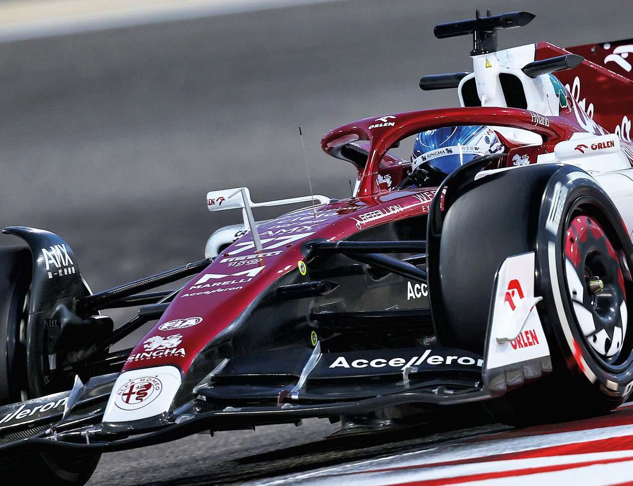
For the Sauber Motorsport-run Alfa Romeo Formula 1 team, which unquestionably suffered poor performance in the latter years of the previous generation of cars, the revolution has certainly been welcomed, and in the C42, the team’s 2022 challenger, it’s made the best of the opportunity presented to it. At the time of writing it lies sixth in the Constructors’ championship.
Jan Monchaux, technical director, Alfa Romeo
‘The 2022 car has some very powerful devices on it, and it was important to avoid making it too sensitive to non-perfect conditions,’ Monchaux adds. ‘It is about building a car that can perform but will also be able to be set up for the distinctive features of a given track … In this era of F1, you will be badly punished on track if you develop a car that is too sharp in its performance window.
8 www.racecar-engineering.com OCTOBER 2022 like bargeboards. It was a matter of finding the limits of the regulations, and then chasing them down with the design and the technology employed.
As much as porpoising remains a factor with ground effect racecars, teams also have to consider the safety of the driver and the driveability of the car. ‘We ensure that the driver’s ability to keep the car on the track remains under all racing conditions when exposed to these oscillations,’ Monchaux says.
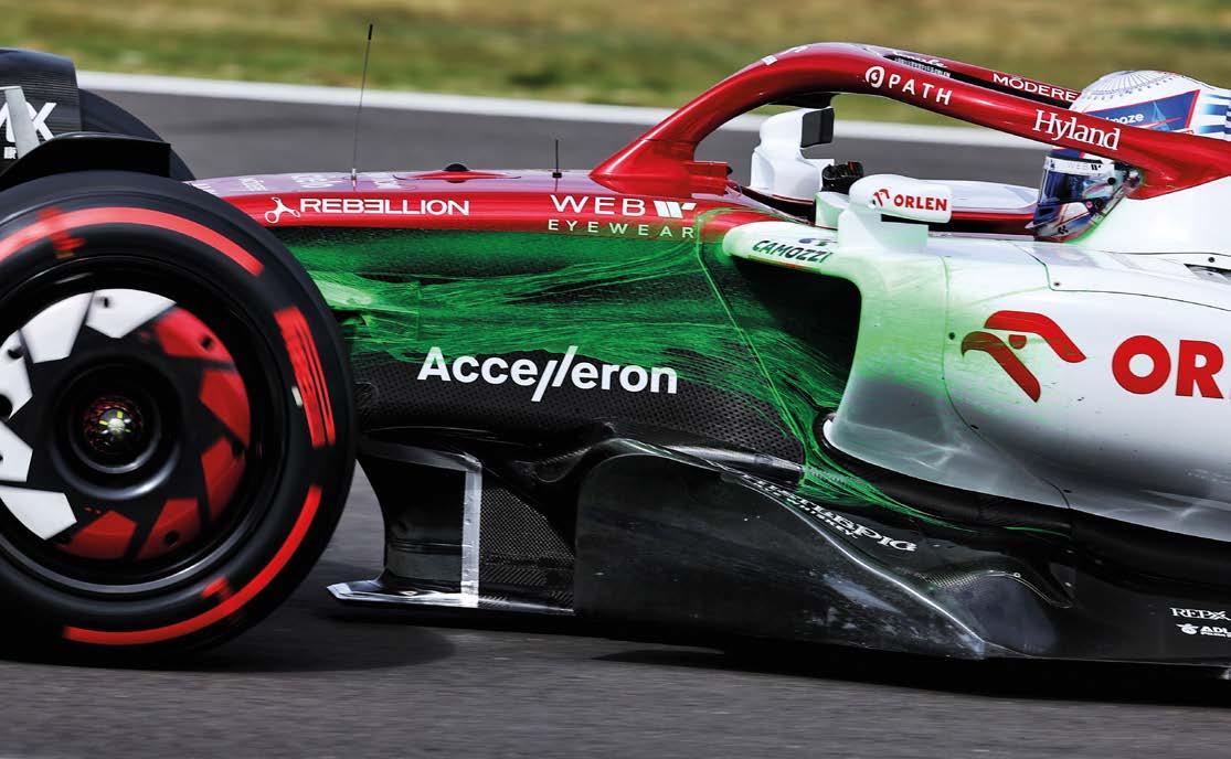
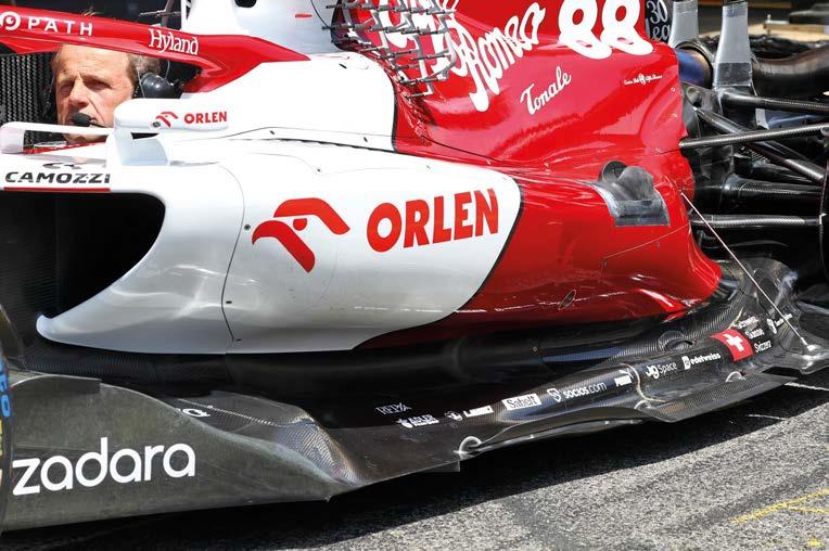
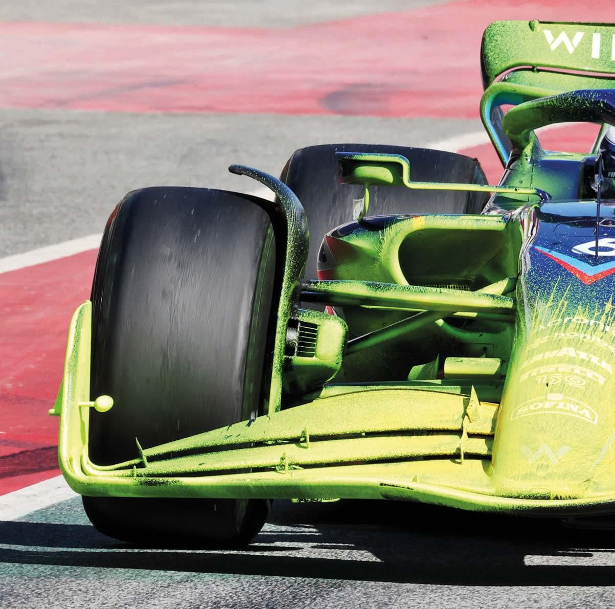
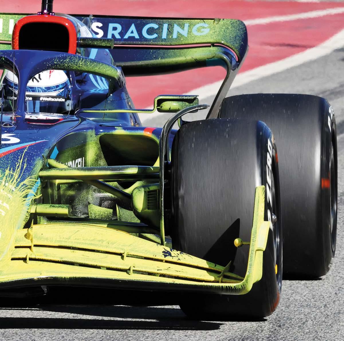
Green flow viz paint sprayed on to the front of the Alfa Romeo C42 clearly shows the airflow converging behind the front wishbones before going on to expand as it enters the sidepod opening
‘The porpoising hasn’t been solved, but the team has found ways to delay the onset of the conditions that cause it’
Floor design
‘There isn’t a simple set-up solution that means you will completely eliminate porpoising,’ Monchaux adds. ‘It will always be there with these cars, so teams have to work with it rather than try to fight it.
The centre of aerodynamic load in the 2022 car is in a similar position to the previous generation of cars, which depended much more heavily on the front and rear wing for axle load instead of relying on the floor aerodynamics. This is because, albeit just a single device, the 2022 floor is an enormous part and generates a great deal of load.
‘This sport is highly professional and strictly respected from a physics perspective, so you equally can’t be conservative in the design and execution of these cars.’
‘Your set-up must coincide with the speeds and average pace on the circuit so that you can move the porpoising excitations outside most conditions on that track. If, for example, you have a set-up where the porpoising is induced at around 240km/h, ideally, what you do is change the configuration to lower your peak performance but push the porpoising phenomena to, say, 320 to 340km/h, which may only occur at one point on the circuit.’
Porpoising issues Platform control is essential in the new era of Formula 1, as the primary performance driver for the car is the underfloor tunnels. Engineers must therefore pay close attention to keeping the flow field stable underneath the car to try to get the flow behaviour in the desired manner for maximum performance. As had been widely reported, many teams have suffered from a phenomenon called porpoising – instability in the flow field underneath the car that causes the car to oscillate dramatically with ride height changes, as a function of the load building and shedding underneath the car. The C42 was not immune to this, and Alfa Romeo suffered badly with porpoising in pre-season testing. It was initially more of a problem regarding damage to the floor underside rather than on-track performance. It was, then, essential for Alfa Romeo to build a more robust floor very quickly to ensure that the structural elements could cope. After that, the team tackled the porpoising phenomenon to try to get the racecar into a window where it would less affect the performance. ‘The porpoising problem hasn’t been solved, but the team have found ways to delay the onset of the conditions that cause it,’ says Monchaux. ‘That was achieved through floor redesign and working on the car’s set-up to ensure that the ride height was more easily maintained across the car’s speed range at each track.
FORMULA 1 ALFA ROMEO C42
‘I will not say what ride height and stiffness we are running on the car as this can be a competitive advantage, but there are also a series of different schools of thought that one can observe up and down the grid to battle this phenomenon.’
‘The rear tyre jets are more critical to manage now that the car relies so heavily on underfloor flow to produce downforce,’ Monchaux adds. ‘At some points, the tyre jet and all the losses it produces are sucked into the diffuser, and it’s hard to get it to disappear. It is one of the significant challenges of this 2022 regulation set.’
Unlike the previous cars, with their many devices working harmoniously to create a load, including the front and rear wings, bargeboards, floor edge designs, brake duct winglets and other aerodynamic furniture, much of this work is now left to the floor.
The reliance on the floor presents some other development difficulties, too. ‘You cannot mix and match the features of the other cars on the grid that you think has more potential like we once did.’ Monchaux says. ‘In the past, you could look at the nose of one car, the bargeboard and sidepod of another and a rear floor and diffuser of a third and combine them to produce a car with some of the behaviours of each. That is because the external surfaces of the previous generation of cars are the primary downforceproducing elements. In 2022, the structure of the aerodynamic regime is entirely different. This approach no longer works; the total aerodynamic package must support the floor as a single entity.’
Sidepods
OCTOBER 2022 www.racecar-engineering.com 9
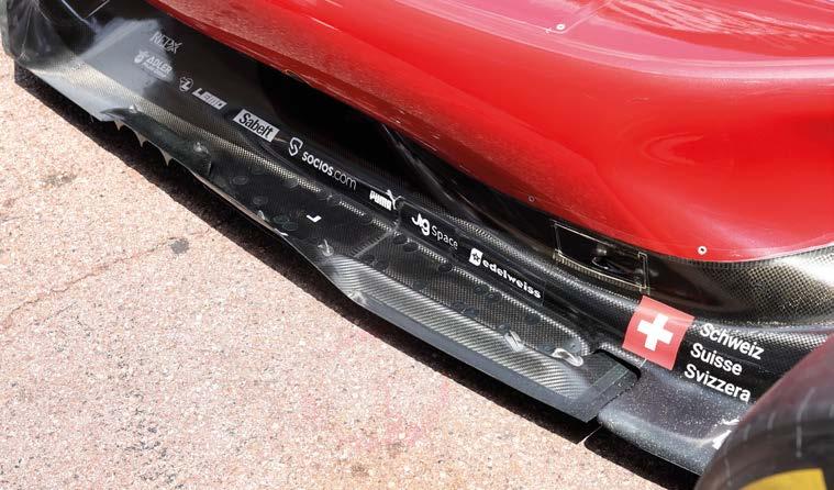
An exit flow device positioned midway down the C42’s floor rejects airstream that isn’t attached to the tunnel flow under the car
There is scope for moving the venturi section underneath the floor where the lowest pressure and, therefore, highest downforce, occurs, within specific tolerances in the rulebook. The venturi’s position also profoundly influences the porpoising, and its location also affects when the conditions for the porpoising will arise. Monchaux would not be drawn on whether Alfa Romeo had changed the position of the venturi under the car after recognising its relationship with the porpoising. Yet having suffered the phenomenon at the start of the year, it would make sense for the team to have done so.
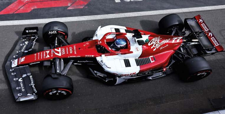
Deeply sculpted section under sidepod leaves space for upper floor surface to interact with under-floor flows and other aero devices
On this subject, he did say: ‘Moving the venturi requires completely redesigning the floor, including all the furniture underneath, and the floor edge details to coincide with a new aerodynamic regime as the flow through the floor must end up in equilibrium.
Slots and cut outs on the floor edges appear on many 2022 cars, and there is an exit flow condition positioned midway down the C42’s floor, which rejects an airstream that isn’t attached to the tunnel flow under the car. Slots further back on the floor edge reingest some of the exit flow condition ejected halfway down the floor section. ‘Effectively, all the devices on the floor edge are controlling the amount of outwash versus in-wash and the ratio at varying speeds seen on the track,’ Monchaux explains. ‘These devices generate vortices or promote air components that are heading inward or outward depending on the difference in pressure on the outside versus the inside of the underfloor.
‘The floor entry fences would need to be reviewed, how the local expansions take place and the flow field conditioning at the front of the floor, as it has a significant influence on the performance of the field downstream of that,’ he added. ‘If you move the point of lowest pressure rearward, it will drop the pressure in the diffuser region, which will naturally cause more in-wash in this area … If the in-wash is ahead of the rear tyres, then the aerodynamic artefacts in that region must work with it. ‘Suppose the downstream aerodynamic features are not aligned with the floor concept. In that case, they won’t be as effective at producing the desired forces because the onset conditions of the flow to these elements will be wrong,’ Monchaux adds. ‘They won’t be able to extract their potential, so there is no golden solution to repositioning the venturi underneath the car.’
‘At higher speeds, the vortices generated at the floor edge add energy to the flow as it’s reintroduced to the underfloor flow field, helping to create more low pressure and, therefore, downforce. They also try to help the car to stay stable at low speed with high rear ride height when the air seal of the floor that maintains the air flow stability under the car isn’t highly energised.
The C42 has a deep, sculpted section under the sidepod to leave space for the upper floor surface to interact as desired with the underfloor flows and other aerodynamic furniture. The upper floor surface is left free, and the flow attaches to that upper surface to generate the desired diffuser behaviour at
‘Removing the complex bargeboards from the regulations for 2022 results in a massive loss of finite control of the flow in this area,’ Monchaux adds. ‘Here, the tradeoff was about getting the devices in this area to outwash the front wheel wake and produce local load, with the resulting load outweighing the losses generated by having furniture in the way of free flow. ‘That trade-off resulted in the hugely complex bargeboard designs that worked hard to generate the downstream load and onset condition for the remaining devices. With these devices no longer permitted in the regulations, there is much less disruption to the flow, which eradicates those loss leading factors that took away from the potential of the flow in this region. ‘Even though there is influence from the front tyre wake, in some ways, the flow in this region is less erratic than it was with the bargeboards,’ Monchaux adds. ‘Now that the small local load generating structures, and other complex things, have all gone, the flow quality into the sidepod openings is far better.’
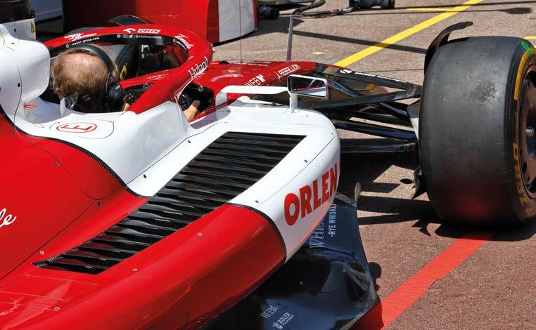
The location of the louvres is the best compromise in terms of getting efficient cooling without polluting flow fields downstream
the back of the car. ‘I think this area will see convergence in the latter part of the 2022 season for those that have the scope to do so, or next year should the engineering resources not allow it,’ Monchaux says. ‘The overall goal is to design this area of the car so that there is the least disruption to the flow and high energy brought to the diffuser.
FORMULA 1 ALFA ROMEO C42
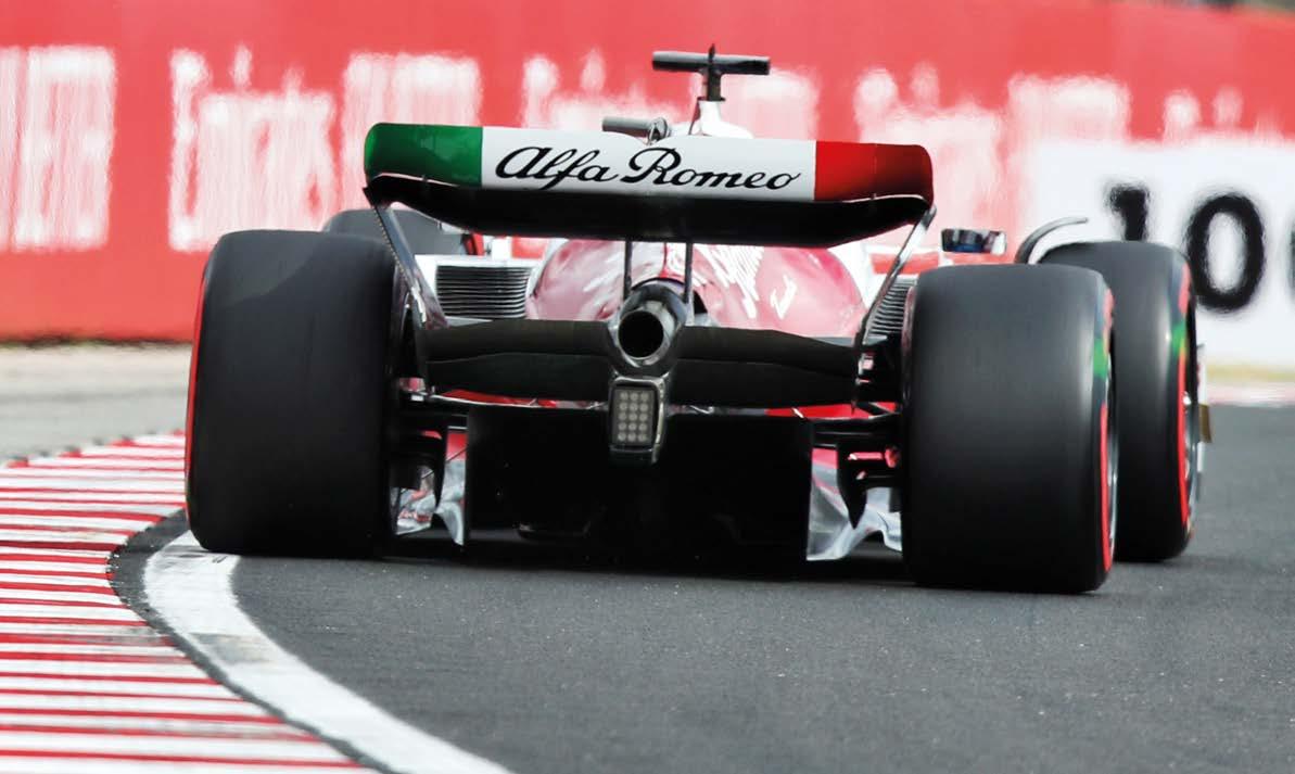
Small flow control features on the trailing floor edge, plus the brake duct winglets and the dual element beam wing, all work together to aid diffuser performance and efficiency
In cool conditions blanks are placed over the sidepod louvres to keep the desired pressure and temperature delta across the coolers
Louvres Meanwhile, the use of louvres for extracting high-temperature air from coolers is far more prominent in F1 2022 than ever before, partly as a function of the regulations, which
Alfa Romeo has opted for a dual-element beam wing. ‘There are different schools of thought regarding the number of elements the beam wing has,’ Monchaux says. ‘It must comply with the rest of the car concept. How you bring the flow to the beam wing from the stream on the outside of the coke panel is important because the way that flow interacts with the rear wishbones and other furniture around that area will dictate flow field losses. These will have to be compensated for by other high-energy streams feeding the beam wing to make it work as hard as possible.’
Suspension
OCTOBER 2022 www.racecar-engineering.com 11 support this type of high-temperature airflow extraction.
The 2022 regulations see the cars carrying more weight than any previous Formula 1 racers – with a 795kg minimum weight – and Alfa Romeo has put a lot of emphasis on the weight of its C42, ensuring that it would start the season below the minimum, so the team is able to play with the racecar balance with ballast. ‘We focused our weight-conscious efforts on the car’s heaviest elements, such as the chassis, which weighs around 95kg,
‘From a purely thermal point of view, these louvres are doing their job; they are efficient and cheap,’ Monchaux says. ‘But from an aerodynamic point of view, they are not the best solution because they generate losses that pollute the airflow you want to keep stable with good energy towards the rear of the car.
a huge number of losses to the flow field that the beam wing and rear wing, and diffuser, depend heavily on.’ Beam wing
C42 features pushrod front suspension. Alfa had planned damper developments for this season, but new regulations scuppered this
Jan Monchaux, technical director, Alfa Romeo
because if you get something wrong by one per cent there, you could be adding unnecessary kilos to the car,’ Monchaux says.
The spring and damper design scope under the new regulations means there has been minimal development here, compared to the previous generation of Formula 1 cars.
‘Also, the new safety regulations for the 2022 chassis mean that the optimisation path for the chassis’ structural behaviour was very different from previous seasons.
‘We also had to re-engineer the rear crash structure and the gearbox casing as this year there were new specifications, which could have led to extra weight on the car if it wasn’t designed properly,’ Monchaux adds.
‘Suspension used to be an area of the car where you could do a lot,’ says Monchaux.
‘We are back to traditional suspension design with the geometry and kinematic installations following a narrow route to achieving the desired behaviour of the car. There are very few different interpretations of the suspension design that we’ve seen throughout the grid.’
The beam wing sits underneath the main rear wing element and its primary role is to help extract flow from the diffuser. It allows the diffuser to run without a Gurney flap that would otherwise do the same job; a beam wing is a much more efficient solution to generating low pressure at the diffuser. It’s fed by the airstream that flows over the top of the rear bodywork around the coke panel area.
‘The high energy flows desired by the diffuser means that the rear-end packaging is far tighter than ever, so the openings at the back of the bodywork are much smaller than in the previous generation of cars,’ Monchaux adds. ‘The louvres on the bodywork are where the entropy that they introduce to the flow field immediately around them won’t pollute the flow fields rearward of where they are. If they were to be located on the underside of the sidepod or low down in the coke panel area, in that case, they would certainly interrupt the stable air flows that are being introduced to the rear downforce-producing elements at the back of the car.
Weight
Alfa Romeo opted to design and develop its own gearbox casing to marry with the 2022 Ferrari power unit, which then enabled it to design and build its own rear suspension layout and thus design the tail end of the gearbox to work in harmony with its own diffuser design. This concept was only possible because of the relationship between the supplier, Ferrari, and Alfa Romeo as the customer. Some of the other teams on the grid have a partnership or extended team relationship with their suppliers which means they are obliged to run with the same gearbox casing and rear suspension design as the supplying team.
‘The high energy flows desired by the diffuser means that the rear-end packaging is far tighter than ever before’
‘The damper regulations evolved quite late in the day before the start of the 2022 season, which killed many of the highperformance ideas we had on the table for new dampers in this era,’ Monchaux adds.
‘Taking louvres away from the sidepod area and moving them to a bigger opening at the back of the engine cover would introduce
‘We wanted to have a weight saving mindset throughout the design office early in the design process of this car, so that there was less risk of having to redesign things from a weight perspective because saving weight is one of the most expensive development paths. If you weigh the components right the first time, then you are just spending the development efforts optimising the components for performance, which is less resource-heavy than weight saving.’
‘We all lost the hydraulic suspension, which was a great way to have authority on the platform control, meaning it’s not so easy to do that now. Still, it is not impossible to find some fast set-ups with the more straightforward and much cheaper suspension regulations we have now.
Succession
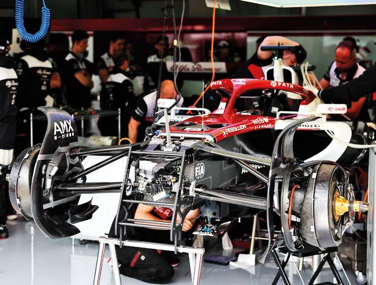
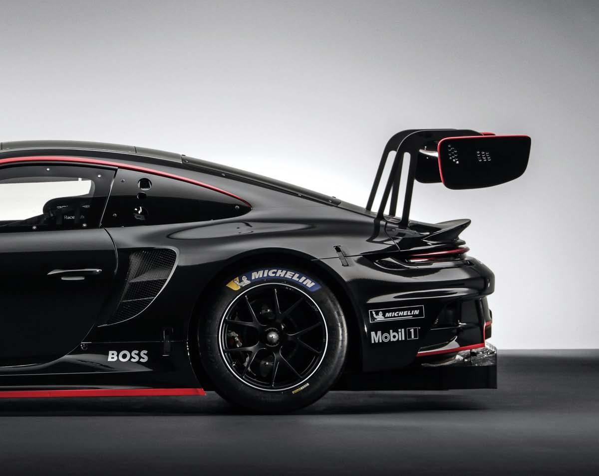
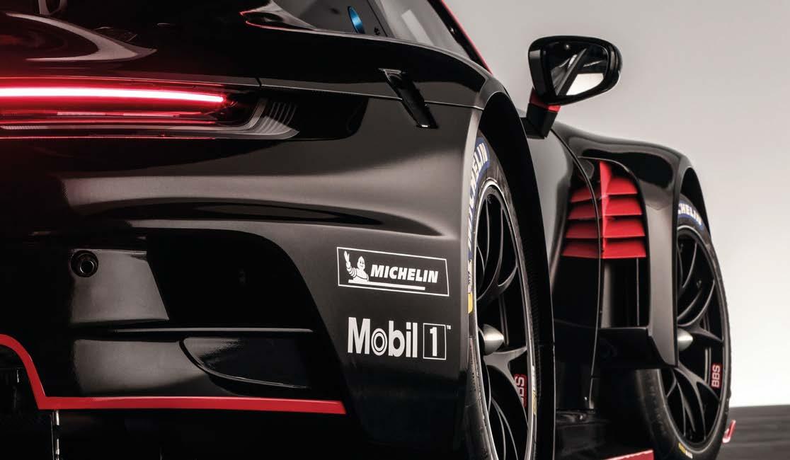
With revised aero and a larger capacity engine, Porsche has focused on driveability and durability in its new 911 GT3 R, but will the 992-based car prove to be better than its illustrious predecessor?
GT3 PORSCHE 911 GT3 R 992
The 992 version of the 911 GT3 R has been designed with customer racers in mind. Porsche will be hoping it can match the commercial success of the 991 incarnation, 83 of which are currently competing
By ANDREW COTTON


OCTOBER 2022 www.racecar-engineering.com 13
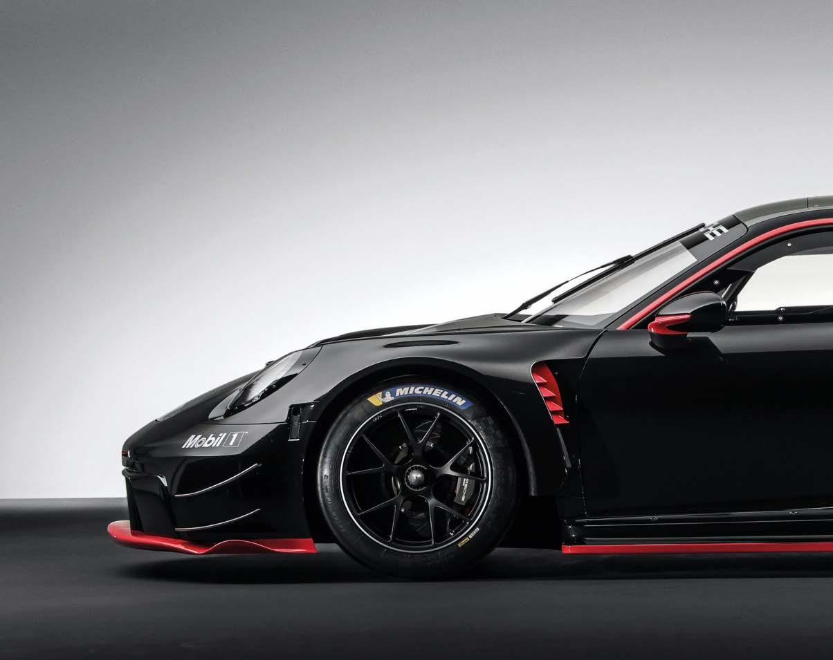
Porsche’s next generation GT3 car has now completed its test programme and will be made available for competition starting at the Daytona 24 hours in January 2023. The company has made a number of changes to its previous model, including revised aerodynamics, an engine upgraded to 4.2 litres, wider track, longer wheelbase and a wealth of safety features, all targeted at making the car easier to drive, more durable and also faster.
The two key areas of development for the 992 GT3 R are the engine and the aerodynamics. The development team says that everything has been designed to try to improve driveability, particularly for the customer drivers, but there are clear differences in potential performance compared to the 991. Porsche extended the wheelbase and the track in order to improve the stability of the car, and in doing so extended the width of the floor considerably. That gives more opportunity for downforce generation, but it has also made other changes to the floor area. The splitter height has been raised, so the section ahead of the front axle is higher than the rest of the floor. There is a step just by the front axle where the floor reverts
The new Porsche 911 GT3 is better balanced on the medium and high speed circuits, according to the test drivers
The base model is the 992 GT3 production car, the choice of not waiting for the GT3 R version having been made early on. This allowed the development team to start work in the summer of 2019. The team looked at all the weaknesses of the 991 Generation 2 and sought to fix them with the new model. Since that point the car has undertaken a massive development programme in preparation for its launch, during the Spa 24 hours in July 2022. Spa saw 66 GT3 cars from nine different manufacturers take the start – showing that this race has become the showcase for GT3 competition. However, even that race will not be the pinnacle of this new car’s career, because in 2024 the GT3 cars will race at Le Mans, and each of the manufacturers that has produced a new car will be hoping that the draw of the great race helps to drive up sales. Porsche has no fewer than 83 of its 991 Gen 2 cars competing in 2022, and it hopes that the 992-based 911 GT3 R will do even better in the coming years. The new car is the latest in a long list of new models that have been released. From BMW in 2021, to Lamborghini earlier this year, Ferrari and now Porsche, the category is rapidly seeing an overhaul of machinery ready for the new era. The 992 GT3 is built to a completely new set of regulations compared to the older car. Gone are the days when a committee decided what was permitted and a manufacturer had to go cap in hand to ask that its development be accepted. Now a stable set of technical regulations has been created by the FIA in conjunction with the manufacturers and the latter have the chance to build more extreme cars. The limiting factor is one of cost, and the fact that the cars are sold as customer products, occasionally competing in factory hands.
Aerodynamics


GT3 PORSCHE 911 GT3 R 992
‘We have elevated the splitter, and with the elevation we have turning vanes in place guiding the air through and under the car,’ say, Maximilian Muller, Porsche Motorsport race support, GT3. ‘The splitter being higher takes away the aero sensitivity, so as the car dives down under braking the car stays in the aero window. You notice [the difference] at all speeds. Any time you are touching the [floor with your] splitter you take your own airflow [from the diffuser].’ As is the case with the Ferrari 296 GT3, unveiled in the summer, the centre section of the nose is slightly raised, allowing more air to channel under the car and drive the diffuser harder. The splitter has a spring that pushes down on it, which allows some flexibility in case of kerb strikes. The idea of the design is not only to make it more robust, but also to allow drivers to maintain performance even when driving in traffic, where airflow is often disturbed.
The increased wheelbase, from 2459mm on the old car to 2507mm on the new one, has come about despite engineers wanting to push the engine further towards the centre of the racecar. The rear lights are 60mm further back compared to the out-going car. Cooling for the engine is fed through the cockpit. The older car had a waiver for this as there was no other way to do it, but now it is written into the regulations, so there are no grey areas for the design team here. But what they are not so sure about is what happens in the really hot races, such as Sebring or Le Mans. They do have the option of separating the cockpit with a plastic insert behind the driver’s seat, but that would allow the air conditioning to cool only half of
OCTOBER 2022 to minimum height, and the team says that is due to managing pitch sensitivity and maintaining airflow to the splitter and the underfloor even under heavy braking.
‘The splitter being higher takes away the aero sensitivity, so as the car dives down under braking it stays in the aero window’
14 www.racecar-engineering.com
Maximilion Muller, Porsche Motorsport race support, GT3
Porsche has sealed off the floor as much as possible, leaving holes only for the air jacks to lift the car during a pit stop. Previously there had been ducts to feed cooling air to the brakes, but these have been relocated to the front of the larger rear wheel arches, leaving a four-piece, continuous floor.

Taming the rear axle was one of the main areas of development for the engineers, as was generating more grip through better aerodynamics. The old car was quick to oversteer, which was difficult for the customer drivers to manage, but the new one is now better balanced on the medium and high speed circuits, according to the test drivers. The change to the angle of the driveshafts was slightly mitigated by a change to the angle of the engine. Like Ferrari, Porsche inclined the engine from the front by 5.5 degrees, to allow for a more aggressive diffuser. That diffuser angle of attack, and the place at which it can start to rise from the floor, is still less effective than the competition, according to Porsche, but such is the limitation of running a rear-engine car.
OCTOBER 2022 www.racecar-engineering.com 15
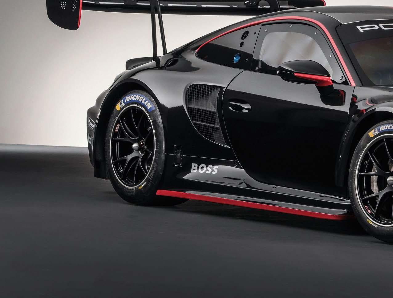
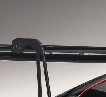
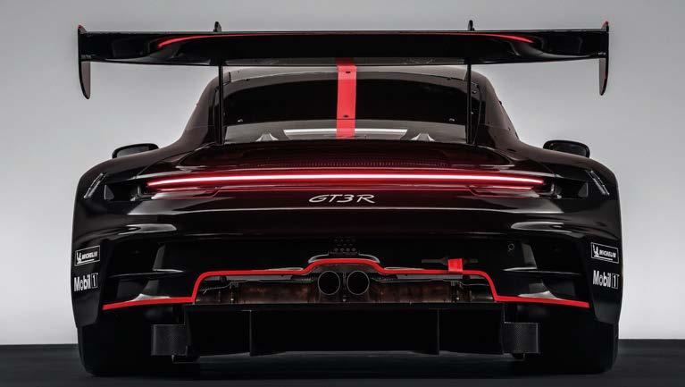
‘The engine has been inclined to the front, obviously as far down as we can without compromising the behaviour on kerb strikes, which was an issue on the old car, we had to address it in 2019,’ Muller says. ‘That was the best compromise for centre of gravity, having a low engine and not damaging it. The engine was tilted with the 991 Gen 2, the update that Opposite left: The splitter height has been raised, as has the centre section of the nose. Above: Porsche has extended the wheelbase and the track in order to improve stability, which means a wider floor and the associated aero benefits. Below: The engine location has been moved forward, the rear wheels rearwards. The car now also sports a swan neck wing support
Porsche has sealed off the floor as much as possible, only leaving holes for the air jacks to lift the car during a pit stop
the rather large greenhouse, which is made additionally hotter by the location of the power unit and gearbox.
Power housed
There was no option to switch around the engine and gearbox, as was the case with the controversial GTE car, but that didn’t stop Porsche moving the location forward, and the rear wheels rearwards, which means there is a greater angle on the driveshafts.
There was some discussion while developing the 991 Gen 2 car as to whether or not to run a turbocharged engine, but the decision was made to stick with an N/A concept, which has been carried over to the new car. The turbo engines have their power curve adapted to a normally aspirated engine anyway, so there is no advantage in using one. Also, for Porsche there would be 40kg more weight at the rear, a higher centre of gravity, increased tyre wear and more wear on the transmission with the turbo option.
Suspension Carried over from the previous car is the double wishbone front suspension concept, with attention paid to improving the precision of the steering, as well as its serviceability. Meanwhile, at the rear the relocated engine meant the team expects better tyre wear, a big issue with the old car.
The engine is still based on the 992 road car, and so is a water-cooled flat-six with 4-valve technology and direct fuel injection. To help with the shifting of the engine to a more central location, auxiliary units such as the alternator and the air conditioning compressor were moved a metre forwards and down into the space in front of the engine and gearbox. The sequential 6-speed constant-mesh gearbox is derived from the current 911 GT3 Cup car.
GT3 PORSCHE 911 GT3 R 992
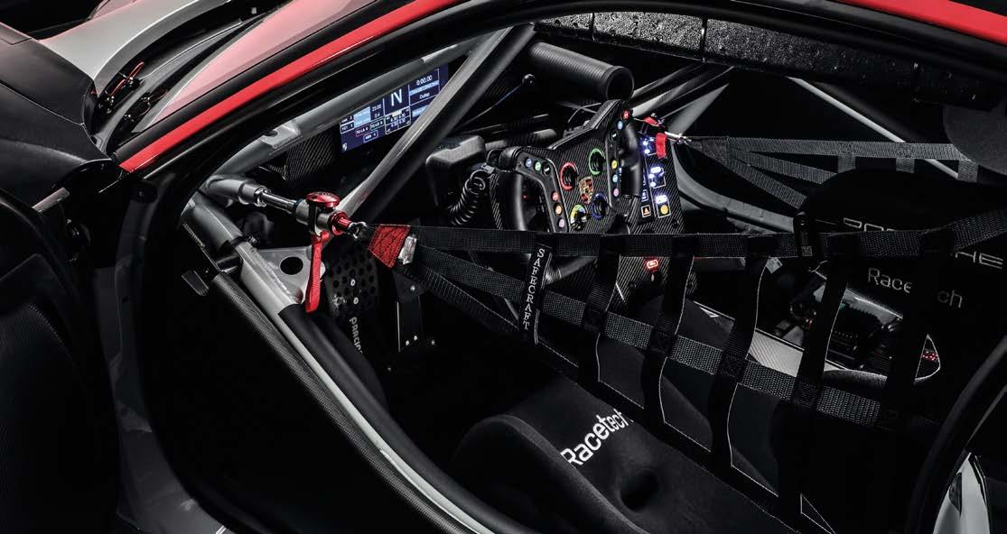
With wider sills there is more bodywork between the driver and the outer skin of the 911 GT3, but for added safety Porsche has also moved the seat closer to the centre of the racecar To help with the shifting of the engine, auxiliary units such as the alternator and the air conditioning compressor were moved a metre forwards
The focus for engine development was not achieving maximum performance figures, again due to the balance of performance system that would have ultimately resulted in the car being penalised anyway.
16 www.racecar-engineering.com OCTOBER 2022 we did in 2019 for the kerb strike behaviour, with the gearbox coming down and the engine up a bit. We are still limited compared to an RSR set-up where we had the engine turned around, but the diffuser can start more from the front and be more efficient.’ Moving the intakes for the brakes to the side was possible due to the increased track, but that has left a large area above the rear wheel that’s pretty much big enough for a large pizza. The flared wheel-arches are slightly reminiscent of the 911 Carrera of 1974, but again Porsche was not looking for ultimate aerodynamic efficiency here, it was more about getting into the FIA performance window in all conditions. For that reason, the rear wing is mounted under swan neck supports, but they are angled towards the rear of the wing rather than from behind, which would leave a clean leading edge. Cooling was clearly a big priority for Porsche when designing the airflow over the car, and with the front-mounted centrally located radiator there was little that the team sought to change. ‘We improved the radiator itself, because we want to be prepared for hotter races,’ explains Muller. ‘We had races in Spa with 33degC. The car is racing in IMSA, where you have green grass right next to the track, so you run wide and the radiator is blocked, so you don’t want that. The AC condenser is next to the radiator, similar to the old car, so where the airflow is changed compared to the old car, over the top it has not changed so much, but on the underfloor and the side it has changed.’ One of the bigger changes with the car is with the fixing of the bodywork to the chassis. While the regulations make certain demands in terms of how each part is secured to the car, Porsche has optimised these areas to make life easier for the mechanics and engineers working on it. Engine The other main area of development is the engine. The old car ran a 4-litre engine, based on the 3.8 that was used in the road car, but with the GT3 production car increasing size to 4.0 litres, so too can the racecar, to 4.2-litres. That has produced more power, and more torque, much to Porsche’s delight. Also delighted will be the drivers, who will hopefully have a more responsive engine to help them navigate through the traffic.
‘One of the main targets of the development of the car, was to improve the driveability, so not the one-lap performance but the driveability over one stint, and how easy we can make it for a driver, no matter what level of driver,’ says Muller. ‘At the bottom end it is a nine per cent increase [of torque], but in the sweet spot it is a true 911, high revving naturally aspirated engine, it is more like a four to five per cent change.’
Offering the latest in technology, Penske Racing Shocks designs, develops, and manufactures high performance suspension products for race applications. Performance Can Be MeasuredUse The Best Tool For The Job PowerfulQuietPrecise


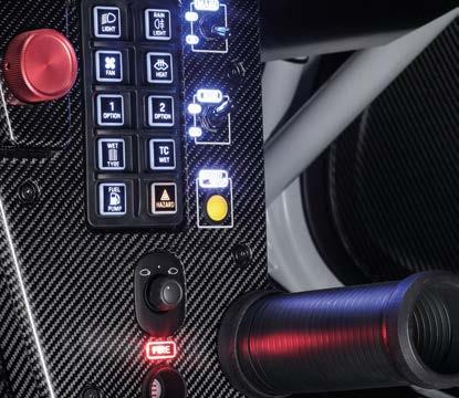
The development team at Porsche has also ensured that set-up changes are quicker, which helps in the limited practice and qualifying sessions, while the cockpit is laid out better, with improved switchgear location and an easy to manage steering wheel.
The older car runs a 4-litre engine but this one packs a 4.2-litre unit, while its relocation in the chassis has meant that Porsche now expects better tyre wear; an issue with the 991 version
Brakes also received the Porsche development treatment, with a change of supplier to AP and with a new dry-break system that allows for a quick brake change.
Porsche has targeted a 12-hour race without the need for a brake change and while it acknowledges that customer teams will try to do 24 hours without a pad or disc change, it prefers to make it easy to do so.
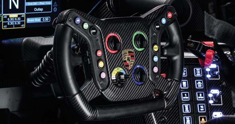
Improved switchgear location is just one of many ergonomic mods
‘We optimised the brake cooling to allow more margin,’ says Muller. ‘The internal flow of the disc is improved and one of the bigger changes for the teams is service-friendliness, so pit stop speed. Now we have quick connectors for the brakes on the chassis side and the caliper side, so on a hot pit stop you just undo the caliper side and take off the caliper and disc, which is a carry-over from another project. You don’t have to worry about the brake line coming through.’
18 www.racecar-engineering.com OCTOBER 2022
Safety first With all these changes the performance of the car should be more stable over the course of a one-hour stint, says Porsche. In a BoP formula being able to run the same lap times at the end of the stint as at the start is key. But it’s not just about performance, and the development team also made use of the changes to improve driver safety. With the wider sills under the doors there is automatically more bodywork between the driver and the outer edge of the car, for instance, but Porsche has gone further and moved the seat closer to the centre of the car. Shift paddles on the Porsche wheel actuate a 6-speed constant-mesh gearbox which is derived from the current 911 GT3 Cup racecar
GT3 PORSCHE 911 GT3 R 992
As with all the GT3 cars, there is a wide range of adjustment to allow the teams to run on different tyres according to the series in which they compete. While Pirelli is dominant in SRO-based series, Michelin dominates the US market in IMSA, and it looks likely that Goodyear will win the contract to run GT3 rubber in the World Endurance Championship when the category goes pro-am in future. In Germany tyre choice is even more open, and so the cars have to be adaptable, and for this Porsche has also upgraded the differential.
Front: single-piece alloy rims, 12.5J x 18, tyre size 30/68-18.
Wheels
‘It was primarily about our customers being able to drive the racing car fast for longer’
TECH SPEC: Porsche 911 GT3 R (992)
Rear: Single-piece alloy rims, 13.5J x 18, tyre size 31/71-18.
As is now pretty much standard in GT racing, the seat is fixed with the pedal and steering moveable according to driver height and preference. This is to allow medical services access to the driver’s head through a hatch in the roof in the event of an accident, to help stabilise it before removal of the driver from the car – the carbon roof is an idea carried over from the previous car but, as this one is based on the GT3 model, there is now no bubble in the roof. Seat belts have also been improved, with the clasp developed to allow quicker pit stops. Having ditched the clutch pedal to the left of the driver’s foot, there was more space, and the development team at Porsche decided to fill that to reduce the possibility of a lower leg injury from either side-impact, or the driver getting their feet caught up in the pedals. ‘We had the side impact on the old car, but we enlarged the foot protection so that the feet don’t slam into the side of it,’ says Muller. ‘The ABS is sitting there [beside the lower left leg]. We tried to shift as much weight [forward] as possible. [The ABS] used to be behind the driver, but it is moved to the left side, mainly because we don’t have a clutch pedal. It is an electronic clutch.’
Suspension Forged aluminium control arms and top mounts, stiffness optimised; high-duty spherical bearings with dust protection; wheel hubs with central locking; 5-way adjustable racing shock absorbers, motorsport-specific valve design and blow-off function; suspension adjustment via shims; sword-type anti-roll bars, adjustable on both sides; spring travel potentiometer; tyre pressure monitoring system. Front axle: double wishbone, adjustable ride height, camber and toe; electro-hydraulic power steering. Rear axle: multilink suspension, adjustable ride height, camber and toe. Racing driveshaft with tripod flanges.
The headlights have been developed in conjunction with the 963 Prototype design team, so extra lamps will not be required for the 24-hour races
Engine Water-cooled 6-cylinder boxer, rear-mounted; capacity 4194cc, stroke 81.5mm, bore 104.5mm; max rpm 9250; power 416kW (565PS); 4-valve technology; single throttle butterfly system; direct fuel injection; Bosch MS 6.6 engine control unit; dry sump lubrication with oil-water heat exchanger; single mass flywheel; race exhaust system with twin tailpipes and DMSB certified catalytic converter.
Transmission Porsche 6-speed sequential constant-mesh gearbox; shift paddles on the steering wheel with electronic shift actuator; mechanical limited slip differential with adjustable pre-load system unit; three-plate carbon race clutch.
Sebastian Golz, 911 GT3 R project manager
While the new GT3 car is more expensive than the 991 (510,000 euros plus taxes), Porsche has thrown in some of the parts that were optional on the old spec sheet, including a heated windscreen, wheel travel sensors, brake temperature sensors and a tyre pressure warning system that is now acting as a performance balancing tool in IMSA racing. Further options include a sensor package for laser-measured ride height, master cylinder brake travel sensors, track temperature sensors and an endurance kit with increased internal lighting. External lighting will not be enhanced for the 24-hour races as Porsche has shared the development of the part with the team of the 963 prototype. ‘We got rid of the aux’ lights,’ says Muller. ‘Everything is done through this light, even the 24-hour races. It is sufficient from the light quality point of view. With the current car we are in a good spot, and this is another improvement.’ The car will be rolled out through the 2023 season as Porsche will not be able to produce 83 cars in time for Daytona in January. However, some teams will start to receive the cars before the end of the year in order to prepare for the race. The European season will start later in the year, which should relieve the pressure on Porsche a little.
Safety 6-bolt carbon racing seat pursuant to FIA 8862-2009; 6-point safety harness for use with HANS; longitudinally adjustable pedal assembly and adjustable steering column with steering angle sensor; 4-post air jack system; valve mounting points on either side; 117-litre FT3 fuel cell in front of the racecar.
Wheelbase: 2507mm; length: 4619mm; width: 2039 mm (front axle); 2050mm (rear axle). Weight Base weight: 1250kg (depending on BoP classification).
Brakes Two independent brake circuits incorporating front and rear axle brake pressure sensors, driver adjustable brake force distribution via brake balancing system; racing brake pads; optimised brake ducting; brake temperature sensors; ergonomic brake pedal positioning for left and right foot braking; Generation 5 racing ABS from Bosch. Front axle: 6-piston aluminium monobloc racing brake calipers, anti-knock back piston springs; internally vented multi-piece 390mm x 35.7mm steel brake discs; aluminium brake disc chamber. Rear axle: 4-piston aluminium monobloc racing brake calipers with anti-knock back piston springs; internally ventilated multi-piece 370mm x 32.1mm steel brake discs; aluminium brake disc chamber.
OCTOBER 2022 www.racecar-engineering.com 19
‘We hit the bullseye with the enormously successful predecessor,’ said Sebastian Golz, the 911 GT3 R project manager, in a press release. ‘Our task was less about making the new 911 GT3 R even faster – the classification within performance windows set by the BoP quickly cancels out this advantage. For us, it was primarily about our customers being able to drive the racing car fast for longer. This requires durability, and that is why we focused predominantly on improved driveability. This is reflected in the new 4.2-litre engine’s broader usable rev band, more stable and constant aerodynamics and lower loads on the rear tyres, which [gives them the] potential to last longer.’
Chassis and body Lightweight body featuring intelligent aluminium-steel composite design; mounting points for lifting device; removable rescue hatch in the roof; welded-in roll cage; approved for co-driver use on circuits.
Electrical system 992 EE Motorsport architecture; new easier-to-use Porsche toolset with more streamlined handling; latest generation Cosworth electronic components; Porsche logger unit; Porsche power box; 10.3in Porsche colour display with integrated RLU; leak-proof LiFePo4 battery 12V, 40Ah in the passenger footwell; 210A alternator; digital touch panel with multi-colour backlighting; single-arm windscreen wiper with direct drive (intermittent and continuous); LED headlights; LED tail lights plus rain light. Attachments for Accident Data Recorder (ADR).
Dimensions

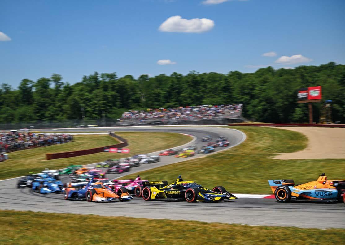
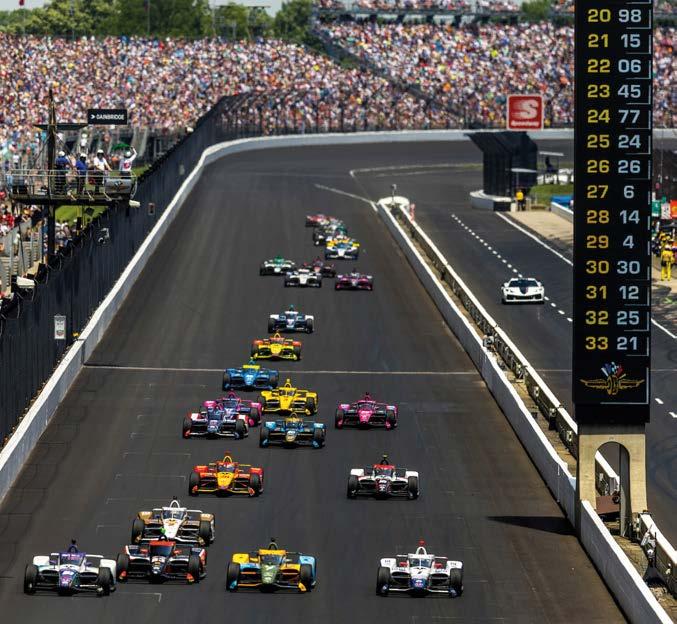
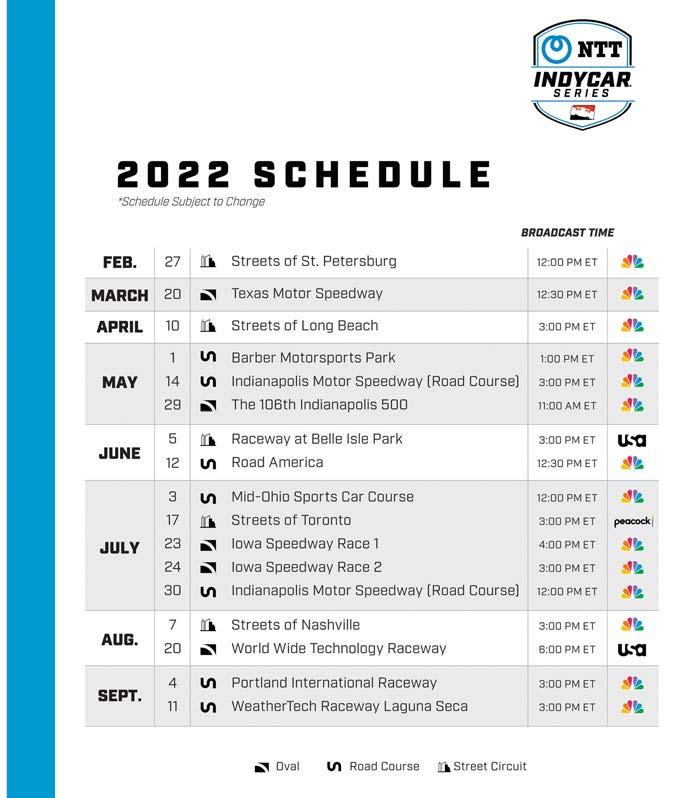
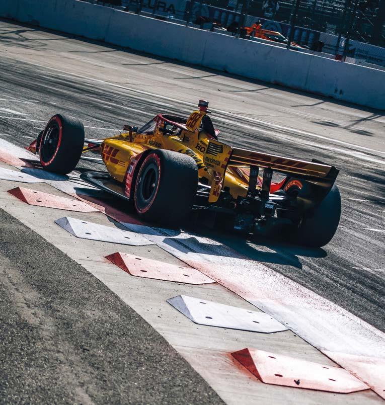
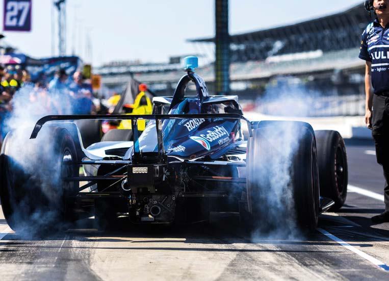
20 www.racecar-engineering.com OCTOBER 2022 With a wide range of oval, street and road courses on the schedule and no teams of strategists to rely on, plotting the tactics for an IndyCar race is one of motorsport’s toughest challenges By GEMMA HATTON INDYCAR STRATEGY Strategy for the high speed Indianapolis Motor Speedway (right) differs greatly from that used at a road course like Mid-Ohio (below) No place for a one track mind
Race strategy in IndyCar is like no other motorsport series on the planet. The number of tyres and the compact race weekend schedule makes tyre degradation impossible to predict, while the teams – which are much smaller than those in Formula 1 – also need to manage fuel consumption, pit windows and full course yellows. But the biggest headache for strategists is the variety of types of track on which IndyCar races. There are three types of circuit on the IndyCar calendar: ovals, road courses and street courses. Ovals can be split into short ovals and superspeedways, where the latter is more than two miles long. Road courses are permanent tracks which feature both right and left turns, and street courses are made up of closed-off public roads or airport runways. This diverse range of circuit types means that lap times can vary from 23 seconds on an oval, to 1m45s on a road course. Consequently, the time lost in the pits relative to the average lap time varies significantly at each race track. This not only plays a major role in determining the pit windows, but also changes the effect of pitting under a full course yellow. Therefore, the optimum race strategy is completely different depending on whether you are racing on an oval or on a road/street course. Lap times can vary from 23 seconds on an oval, to 1m45s on a road course
OCTOBER 2022 www.racecar-engineering.com 21
The 17-round 2022 IndyCar calendar consists of five ovals, seven road courses and five street tracks The Nashville street circuit in Tennessee. The very high probability of full course yellows at a street track like this offers plenty of opportunities to race engineer/strategists who are on the ball


INDYCAR STRATEGY MediaIgnite/AutosportAndretti
With full course yellows capable of completely turning a team’s race strategy on its head, engineers need to be alert
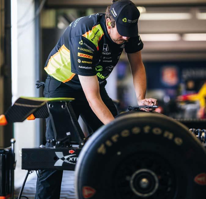
Firestone has developed many different tyre constructions and compounds; yet another variable for race engineers
For quite a long time IndyCar was a fuel-limited series, in terms of a team’s strategy on race day, but recent changes to the racecars, the rubber they run on, and also ageing track surfaces, has brought the tyre life more and more into the equation
OCTOBER 2022
Tyres Traditionally, IndyCar has been a fuel limited series, where stint lengths were defined by fuel consumption. This still plays a role in the race strategy, as the driver’s ability to lift and coast to save fuel could help extend a stint and maintain track position. However, the biggest influencer on IndyCar strategy is now the tyre Yearsperformance.ago,teamswould typically experience negative or negligible tyre degradation during a race, meaning the tyres would actually get faster throughout a stint. This was due to the tyres starting off cold and then warming up to their working window, increasing grip with every lap. Today, however, the tyres mostly experience positive degradation, where grip reduces during a stint and lap times become slower – similar to what we see in Formula 1. ‘I’ve been racing in IndyCar over the last 25 years and I would say that during the majority of the early years, tyre degradation was typically minimal and cars went quicker as weight reduced from fuel burn,’ says Eric Bretzman, technical director at Andretti Autosport. ‘With the introduction of alternate road and street course tyres, we now experience races with significant degradation. Additionally, oval lap times currently degrade and that’s coming from the surface of the tracks ageing as well as our racecars having more power and being much heavier than they were years ago.’ This shift towards tyre limited races has become even more apparent in 2022, where the alternate tyre has much higher degradation. Unfortunately for the teams, the already challenging task of predicting tyre degradation is further compounded by the nature of the race weekend schedule and the number of tyres available to teams. This means that the first time the teams actually get to complete a representative long run is during the warm up session, which is typically a few hours before the race.
22 www.racecar-engineering.com
‘We have two free practice sessions, a qualifying session and then a warm up prior to the race,’ explains Taylor Kiel, president at Arrow McLaren SP. ‘We only get the opportunity to do a long run on a full tank of fuel during the warm up session. So we
The variety of tracks on the IndyCar calendar compounds this problem further.
OCTOBER 2022 www.racecar-engineering.com 23 get some running on representative track conditions, but it’s not a lot of data. Also, ambient temperatures are usually cooler as the warm up is earlier in the day, so we try to account for these with offsets that we build into the models. But ultimately the total track time is not a lot and the structure of the weekend means that we are very rarely ever running at the same time as the race, which is not ideal from an engineering point of view.’
Full course yellows
‘Typically, cars that have completed a pit cycle before a full course yellow will have a track position advantage,’ says Faustino. ‘This is because the leaders will then pit under yellow and will cycle to the back of the cars that have stayed out, assuming they have enough fuel to complete the same numberIndyCar races are often won or lost on the timing of a pitstop. On ovals you generally want to avoid pitting for as long as possible
‘Firestone does tweak the tyres each year as well,’ says David Faustino, lead race engineer at Team Penske. ‘Typically they are trying to tweak the balance between the primary and alternate tyre to get some crossover degradation. But it’s enough of a change, which means going into a race weekend it’s not always obvious how the tyres are going to behave relative to last year.’
For the 2021 IndyCar season, which featured 16 races, this boiled down to 20 different dry tyre specifications and one wet. This is a huge number of tyres that the teams had to model, understand and manage throughout the season.
There are essentially five types of tyres, based on their construction: street course tyres, road course tyres, Indy 500 tyres, superspeedway tyres and short oval tyres. Then there are two compounds, the primary (black) harder compound and the alternate (red) softer compound. On the ovals, teams are only allowed to use the primary compound. However, due to the forces generated, each corner of the car requires a slightly different tyre compound or construction. On street/road courses teams can choose from the primary and alternate compounds, as well as one wet tyre.
‘A lot of our strategy comes down to how IndyCar handles full course yellows,’ says Eric Cowdin, race engineer at Chip Ganassi Racing. ‘On road and street courses you want to pit towards the front of the pit window, because if a yellow comes out and you haven’t pitted, you have to wait until the pitlane opens again, by which time the pack has completely bunched up.’
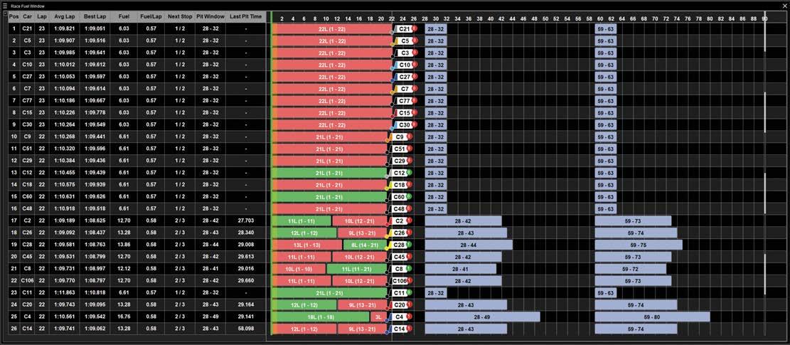
The fuel windows are defined for each strategy prior to the race. These show on which laps a driver needs to come in to the pits in order to make it to the end of the race on the desired plan
To suit the demands of each circuit, Firestone have had to develop a plethora of different tyre constructions and compounds, giving the engineers lots of tyres to figure out.
The biggest variable that is outside of the teams’ control is yellow flags and full course yellows. Unlike other series, if a full course yellow comes out during a race, the pit lane closes. A pace car is then released which picks up the race leader and the other cars bunch up behind. Once the pack is formed, the pit lane opens, giving cars the opportunity to pit before the race goes green. If a car passes the Pit Commitment Line after a yellow, the driver cannot complete a full pitstop (but can repair damage or refuel for two seconds), and has to drive through the pit lane, ending up at the back of the pack. They can then complete a full pitstop when the pit lane opens again.
OCTOBER 2022 of stops overall. With the point structure in IndyCar you usually see the field split 50/50, so in a 26 car field, if you are the leader and haven’t pitted before a yellow, you could end up 13th, which is a substantial hit. So usually cars will stop early and take the risk of having to fuel save for the rest of the race, in the hope that they will get lucky with a yellow where they can then conserve fuel.’ However, on ovals it’s a different story. Pitstops are initially dictated by fuel consumption and a normal pitstop can put a driver two or three laps down compared to the rest of the field. Therefore, by pitting under a full course yellow on an oval, once the pack has bunched up, a driver can complete a pitstop and re-join the track on the same lap – without going several laps down. So, if a yellow falls during a driver’s fuel window, then it is effectively a ‘free’ pitstop.
Eric Cowdin, race engineer, Chip Ganassi Racing
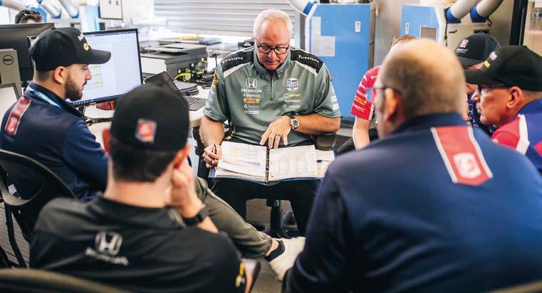
Eric Bretzman, tech director at Andretti, ponders strategies. IndyCar teams have little in the way of live software
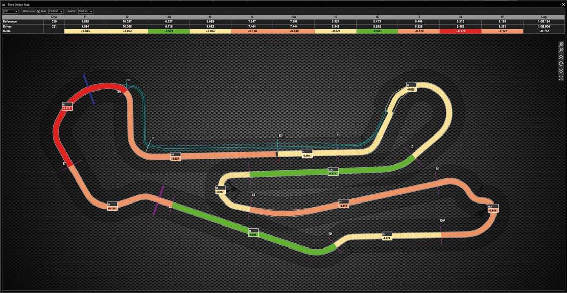
Race strategy software such as RaceWatch from SBG can create easy to grasp visuals that show where a driver is gaining or losing time compared to a reference rival in a race
‘The strategy for ovals is the opposite to road courses,’ says Cowdin. ‘You want to run as long as you dare to try and catch that yellow. But then you also have to consider fuel and tyre degradation. There’s no point staying out 10 laps longer on older tyres if your rival is going considerably faster than you on a new set, because when you do pit, you will come out several places behind them.’
INDYCAR STRATEGY
Race strategy software With full course yellows capable of completely turning a team’s race strategy on its head, engineers need to be alert to this threat and have access to all the necessary information to respond quickly and accurately. However, while in Formula1 and WEC we will see live strategy software on the screens perched on the pitwalls, most IndyCar teams use standard timing data alongside their own strategy tools. Last season, however, Arrow McLaren SP invested in some new race strategy software from SBG, which is called RaceWatch. This is a live prediction tool which synchronises the track data, such as live timing, the race control messages and weather updates, with the car data, including telemetry, GPS and onboard video. The algorithms within
‘The strategy for ovals is the opposite to road courses. You want to run as long as you dare to try and catch that yellow’
24 www.racecar-engineering.com


INDYCAR STRATEGY
RaceWatch then process and analyse this incoming data using statistical models which can predict the probability of an overtake, a driver’s pace during a session, and the latest values for tyre degradation.
‘In Formula 1, a team will usually have a group of strategists to help make the decisions,’ Caulfield continues. ‘But in IndyCar, the person responsible for race strategy is also typically the race engineer, with maybe another engineer supporting them. By streamlining all the sources of data and using clear visuals to display the most important pieces of information, the engineers can spend less time collating data and more time on making the decisions.’
Unlike in Formula 1, there are no big teams of strategists back at base and the race engineers usually take care of the tactics
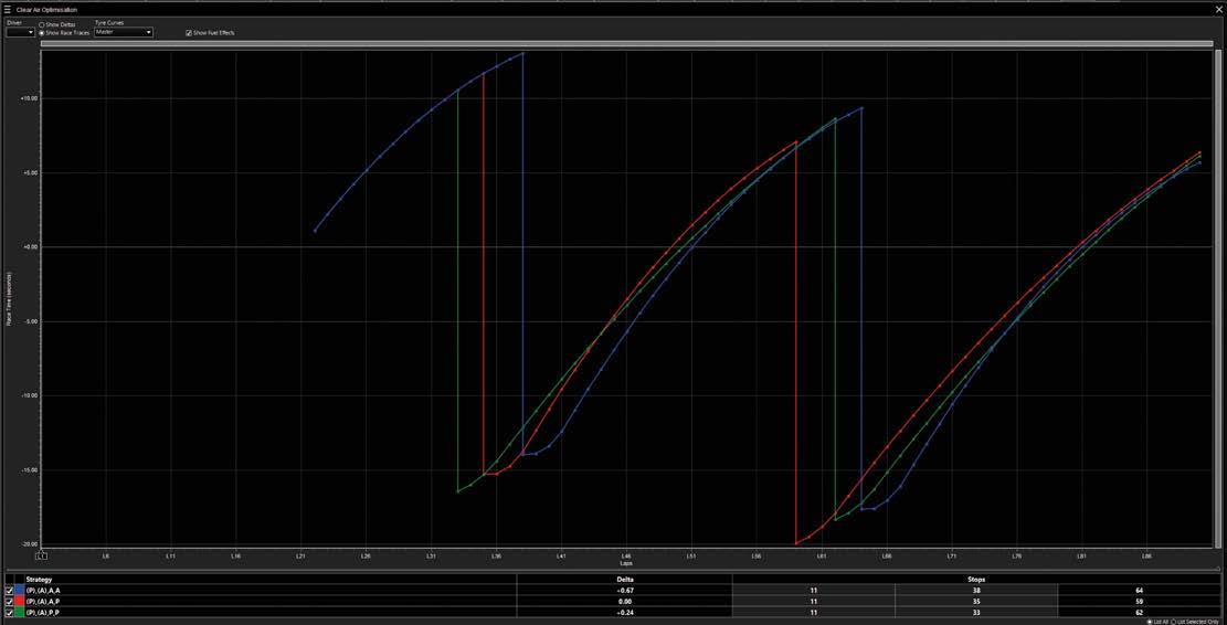
Once tyre degradation has been calculated for each of the tyre compounds, the IndyCar strategists will then conduct a clean air optimisation of the race. This assumes there are no other cars out on track at the same time as their racecar and it defines the optimum strategy based purely on the tyre degradation during the run
Making sure the driver knows when to conserve fuel and not overwork the tyres is a crucial aspect of IndyCar oval track strategy
26 www.racecar-engineering.com OCTOBER 2022
‘Our aim is to help engineers bring all the data they need into one place,’ says Mike Caulfield, senior motorsport product specialist at SBG and a former strategy engineer in Formula 1 at the Mercedes and Haas teams. ‘This avoids them having to manage several spreadsheets and manually move data to populate tools. Instead, RaceWatch automatically picks up all the necessary data streams and updates the models simultaneously.
‘Our aim is to help engineers bring all the data they need into one place’ Mike Caulfield, senior motorsport product specialist at SBG

OCTOBER 2022 www.racecar-engineering.com 27 Heat Exchangers


INDYCAR STRATEGY Oval vs road course aero testing
‘But more teams are struggling with correlation at the high speeds on ovals than on road and street courses. On speedway tracks, cars are running at 230 to 240mph and even full scale wind tunnels can only run at 160mph, so you’re only testing 60 per cent of the loads, deflections and vibrations. That all adds up and makes it difficult to accurately predict the behaviour of the airflow, particularly with ground effect cars that are generally more complex to model.’
‘Strategy software should never tell you what decision to make,’ says Caulfield. ‘In RaceWatch, we try to model the scenarios as best we can and provide all the relevant information in a clear and concise way so that teams can understand the options available to them and the level of risk associated with each. It is then up to the team to decide whether to take that risk or not.’
Testing is restricted and while running at Mid-Ohio (above) is useful, oval tests are better for gaining an aero advantage
RaceWatch was originally developed in 2008 with Honda F1 and it evolved with that team as it transitioned to Brawn and then Mercedes. As well as being supplied to a number of other F1 teams, it has been deployed in other championships including Formula E, WEC and now IndyCar. Currently, engineers at SBG are working with the likes of Arrow McLaren to tailor the software to the unique strategic challenges of IndyCar, giving Arrow McLaren a competitive advantage. This was proven at Texas Motor Speedway last year where RaceWatch helped the team’s strategists predict the tyre degradation and pace of Josef Newgarden who was ahead of Arrow McLaren’s Pato O’Ward. During the race, the team decided to stay in second place and focus on fuel saving. As soon as the RaceWatch data showed that Newgarden was suffering from tyre degradation, O’Ward pushed to take the lead and won the race.
28 www.racecar-engineering.com OCTOBER 2022
There are three elements to the statistical models within RaceWatch. The first is a live snapshot view which is updated every few seconds and predicts how the race will most likely unfold for each competitor.
‘From time to time some teams will run sensors and pressure rakes for either CFD or wind tunnel correlation,’ continues Faustino.
The unique characteristics of oval and road/street courses does not just require different race strategies, but also different testing strategies. Throughout a season, IndyCar teams are limited to four team test days and a twoday Indianapolis 500 open test (excluding tyre manufacturer tests, media tests, rookie tests and new team tests). That four day allocation also includes any full-size wind tunnel and straight-line running.
Whereas, for the road and street courses, teams are running maximum downforce, so only around zero to 10 per cent of the test time is allocated to aerodynamic testing for road and street courses.
The third and final modelling tactic is Game Theory. This is a decision mathematics technique which allows teams to better react to the changing circumstances of a race. For example, if the optimum strategy for a team’s competitor is to complete a two stop race, and for some reason they switch to a three stop strategy, game theory can help teams decide on their optimum response to this change, to try and beat their competitors.
Oval test match
‘That’s why most aerodynamic testing is focused on the ovals. I would say the majority of IndyCar teams dedicate around 25 to 50 per cent of their test time to aerodynamic testing for the ovals.
‘In terms of aerodynamic performance with the current rules package, there is typically more opportunity for us to separate ourselves from our competitors on oval tracks than there is on road and street courses,’ explains David Faustino, the lead race engineer at Team Penske.
The second is the Monte Carlo simulations which allows the generation of statistically probable numerical solutions to problems which cannot be analytically solved. During a Monte Carlo simulation, values are randomly sampled from input probability distributions. Each set of these samples is called an iteration and the resulting outcome from that sample is recorded. This process is repeated thousands of times and the result is a probability distribution of possible outcomes with an associated probability of the likelihood that that outcome will occur. Therefore, the Monte Carlo method does not just show you what could happen, but also how likely it is to happen.
Although IndyCar teams benefit from data collated by manufacturer tests, considering the variety of tracks they need to prepare for, this is still an extremely low amount of testing time. Consequently, teams need to exploit every minute out on track and prioritise the most important test items.
Game Theory is a decision circumstancestoteamstechniquemathematicswhichallowstobetterreactthechangingofarace

OCTOBER 2022 www.racecar-engineering.com 29 The Winners Racing Cooler print.pdf 1 09/05/2022 16:58


Using the UK as an example – though this will be similar elsewhere – there are a number of types of test days, but to begin with it’s worth addressing the controversial practice of testing at track days. Track days are supposed to be wholly uncompetitive for insurance purposes – you’re not supposed to time laps, for example – and single seaters, some specific days aside, are seldom welcome. But beyond all this track days can also be counter-
drivers seat time is important. And if you are in this fortunate position, where your team is free to test, then the first thing to address is what type of day to attend.
ike most things in motor racing, testing is all about time. Get the most out of your test time and chances are it will show in your lap time. These days this is doubly important because at a higher level, from FIA F3 up, there’s very little testing time to be had because of cost-led restrictions. It is, then, vital that teams hone their testing skills at every opportunity.
30 www.racecar-engineering.com OCTOBER 2022
With testing restrictions now common getting the most out of your time on track is critical. Racecar spoke to engineers, team bosses and driver coaches to uncover the secrets to test success
PRACTICAL ENGINEERING TESTING
By MIKE BRESLIN
There are still quite a few opportunities to do just this, too, as many categories do not have major restrictions on testing – most of the junior single seater formulae for a start, as well as the GT series in which giving amateur
thePassingtest
L
XPB
OCTOBER 2022 www.racecar-engineering.com 31 productive for a race team, largely because of the huge performance differences when you have road cars sharing the circuit with racecars, which can cause frustration for all.
Test match Regular types of proper test days are open pitlane (the car goes out at any time); sessioned (groups of similar cars, for instance single seaters and closed wheel cars will rarely be mixed); semi-exclusive (a small number of cars share a circuit with an open pitlane) and exclusive, where you have the track to yourself; the ideal option, but very expensive.
It’s worth pointing out here, though, that the point made above about large speed differentials between cars at track days is also an issue on some open pitlane and even sessioned days; for example ‘closed wheel racecars’, a common category, can cover a multitude of car types.
‘The most important thing is going to the right test day, which I’d say is an open pit lane day with good cars, and with a limit on the number of cars,’ says Mark Wynne, boss of engineering consultancy Penitus Motorsport, who now engineers Mercedes-AMG GT3s at RAM Racing in British GT and GT Cup, as well as at Akkodis in GT World Challenge. Semiexclusive days such as this can be relatively expensive, of course, yet as Wynne points out, it can also be money well spent. ‘If you end up at a day full of Caterhams, then if you’re in the GT3 cars it is a waste of time,’ he says. ‘You bolt on your £2000 set of tyres, and you might as well just set fire to them, because closing speed is 25 seconds a lap, and when you look at a 90-second lap time, you’re going to hit traffic. So you might get just two or three corners. It’s pretty hard for that guy in the Caterham, as well. Yes, it ruins our day, but it’s not fair on him, too.’ Testing is limited in Formula 1 these days, so teams have to make the very best of the time available –flow-vis is a great aid in that respect

Run plan Once you have chosen your test day you need to make a plan for the day, and a run plan for individual sessions on a sessioned day. Of course, the shape of that plan very much depends on what you are trying to achieve. ‘On the Thursday test before a race [for GB3], it’s much more about preparation for the weekend,’ says Ives. ‘Whether you’re concentrating on ultimate lap time or race pace. Whereas, when it’s not directly before a race weekend, you have a bit more scope to try some different ideas.’ ‘It’s not like a track day, just hammering in the laps thinking you’ve got the speed,’ says Wynne. ‘So, from the point of view of planning, you have to understand what it is that you want to achieve, that’s the main thing. Why are you going testing? It’s very easy to plan a million laps, but you need to be on good tyres, you need to make sure you don’t get led down garden paths, running around on knackered tyres, or thinking you’ve got a good car when clearly you’re in a different situation to when you race. If
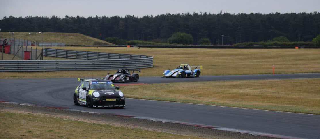
There can be large performance discrepancies between vehicles in ‘closed wheel car’ sessions. Here a Mini is about to be mugged by a brace of Radical SR3s at a Snetterton test day
PRACTICAL ENGINEERING TESTING
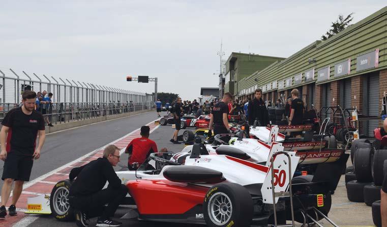
The teams wait for the lights to go green at a GB3 test at Snetterton. Red flag stoppages can always frustrate an engineer’s run plan Checking tyre temperatures. Frequent stops give drivers time to think through the laps and crews the chance to collect data
32 www.racecar-engineering.com
OCTOBER 2022 ‘It’s also important to try and select a day that is as relevant as possible,’ says Eddie Ives, boss of Elite Motorsport, which is active in GB4 and GB3 – formerly BRDC Formula 3 and the UK’s premier single seater formula – plus Ginetta championships. ‘There’s an element of conditions, ambient temperatures and track temperatures and stuff like that, trying to be as relevant as possible to when you go racing,’ he says. Though he adds that circumstances often make this difficult. ‘In the UK, there are not actually that many good quality test days during the season, whereas there are lots in the winter, so you end up doing lots of winter testing, mainly because you get a lot of clear laps, but then the conditions are nothing like they are when you go racing.’
OCTOBER 2022 www.racecar-engineering.com 33 you take GT Cup this year, it is an incredibly aggressive championship with regards to tyres, because you don’t run more than 120km in the day at the race. Which, if you think of Silverstone, five or six kilometres, two-minute laps, you very quickly get to 120km. So, to do a valuable test there, for that type of race, you need a lot of sets of tyres.’
The above points to an interesting facet of testing, and that is that while there may be a whole host of physical variables at the track one of the biggest variables, particularly at entry level and especially in GT racing, can be the driver. But in GTs a driver’s performance
Wills, who helped develop cars for Van Diemen as well as his own Spirit Formula Fords in the past, explains all. ‘The most important thing about testing is you have to be conclusive,’ he says. ‘If you’re going to try different wheels then you should start with the old wheels, set a time, then switch to the new wheels, set a time and compare them. But then you need to put the old wheels back on and set another time, checking again. The thing is, you don’t go out and think you’ve found half a second but in reality it’s the circuit or the driver that’s got faster. This goes for everything, including settings.’
For Steve Wills, who is currently developing the all-new Formula Foundation car (see June issue) in both ICE and electric form, testing is all about endurance right now. ‘What we’ve been doing is mileage, very close to 2000 miles, flat out,’ he says. ‘What we’re looking for is mechanical failures: is anything going to come undone? What’s going to break? Do the brakes overheat? Is it using the oil? Is the water temperature good? And so on.’
Test of endurance
If possible, fielding different cars on different run plans at a test can play dividends. ‘When I work with Akkodis we take four cars and we’re all on different programmes, so we can get the best when we roll forward in a couple of days to the race,’ says Wynne. ‘So you might be banging around with what the public think are crap lap times, but you might be doing high fuel, you might be doing something totally different to what other people are doing. So you can’t even judge your own time. And that’s the other thing with testing. You don’t know if people are running to the BoP, you don’t know if people are running the correct tyres, or are messing about. I mean, you see it very often in pre-season, you get teams that run incredibly quick, to maybe attract a customer. Then, when everyone’s got to run straight, they’re nowhere.’
Ives agrees that it’s important not to get too wrapped up in what rival teams are doing. ‘As a team, we try not to worry about others,’ he says. ‘From a car point of view, you’re concentrating on your car balance predominantly, and if the balance is right, then it tends to be okay.’
For more general performance testing, however, a run plan will consider how many laps the driver will do before coming in, the fuel load, what tweaks will be tested, etc. Early in a car’s development it might also be sent out with settings at their extreme – a fully soft roll bar for instance – to try and gauge the influence of these parts. But when it comes to any ongoing development work at a test it makes sense to take what’s called an A-B-A approach, double checking any apparent improvement with the baseline.
‘We try and work on the corners that the drivers don’t like,’ says Wills. ‘If the driver fears the corner, there’s something wrong, and your biggest chunk of time is probably sitting in a corner where there’s an issue. If you can work on that corner, you should find some time.’
It makes sense to take what’s called an A-B-A approach, double checking any apparent improvements with the baseline
The phenomenon of the circuit getting faster or slower is always an issue for teams at a test. ‘With something like the GB3 cars, they’re pretty susceptible to temperature changes and track conditions,’ says Ives. ‘The hardest bit is making sure you are comparing like for like. At a lot of circuits you will go quite quickly first thing in the morning, and then potentially right at the end of the day, in terms of track conditions. But you’re trying stuff on the car during the day, and trying to get a direct comparison. So sometimes you’re not sure if it’s Throughoutrelevant.’arunthe tyre temperatures and pressures and the like should be checked, and all data needs to be recorded, whether digitally or in a notebook, including the track’s condition and the weather. Off course, the run plan should be focused on what the team is trying to achieve, too, which means identifying areas where time might be found.
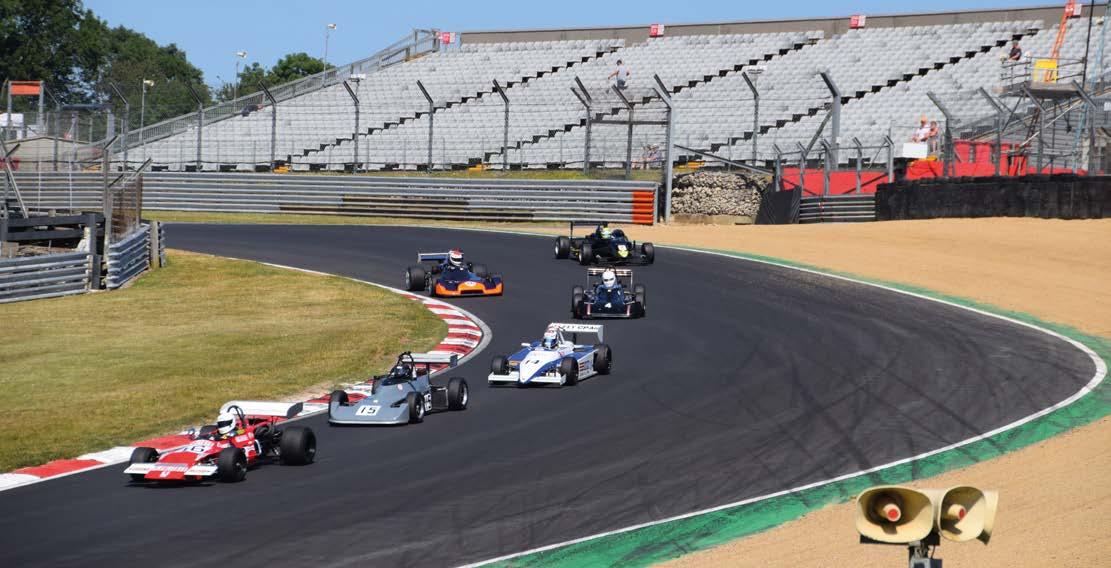
Even if a session is for slicks and wings single seaters (as seen here at Brands Hatch) there can still be massive speed differentials between racecars from different formulae and eras
Effective test drivers should also be technically literate, says Mansell. ‘Sometimes the feedback from the driver’s perspective isn’t as deep as it should be. There’s often work to be done there on the depth and quality of the feedback given, but that also comes from the driver’s mechanical and aero understanding of the car, because they need to understand what the set-up change does to the car and how that’s going to affect the car through each phase of each corner.’
Scott Mansell, driver coach
In GT racing
the amateur drivers will usually have the lion’s share of track time during a test day. This is a sensible approach when it comes to improving the overall pace of the car, as there is less scope for making big lap time gains with the professional drivers
‘Back in the day, it would be a driver’s engineer, or just his mechanic, and now that role is getting split into number one, number two mechanics, race engineers, performance engineers and driver coaches,’ says Ives. Scott Mansell is a well-known driver coach and someone who has tested pretty much every sort of racecar during his racing career – he is also a Youtube personality through his Driver61 channel. Mansell, no relation to Nigel, is clear on the above point. ‘It always comes from the team, from the engineer; the setting-up, the testing plan, and then the coach will just work within that and see if there are any issues in terms of the driving within that set programme,’ he says. ‘Because the driver coach can be a bit more fluid in the advice that they’re giving, whereas an engineer might have a very set plan that they want to follow throughout the day.’
Crucial in all of this is not to let the driver fall into the trap of simply driving lap after lap until the session ends, something that can be tempting given the expense of going testing and the knock-on desire to get value for money. It’s far better for everyone involved if the driver stops for a debrief quite often.
PRACTICAL ENGINEERING TESTING
But most good drivers will actually enjoy working with their engineers to develop the car at a test. ‘I love trying to develop a car,’ Mansell says. ‘With the racecar you change one thing and then it affects another section of the car and you can go back and ‘There’s often work to be done on the depth and the quality of the feedback given by the driver’
Run plans for a test session should be made with the condition of the tyres and their relevance to race day very much in mind
Changes should always be compared with the benchmark, to make sure it’s not the track or the driver that’s improved
34 www.racecar-engineering.com
‘It’s vital for a driver to talk through their impressions as much as they can,’ says Wills.
‘Do about 10 laps at the start of a test just to dial themselves in and then come in and chat with someone and then think about making some changes. But the important thing is to give themselves some thinking time, ideally talking things through, there’s certainly little point in pounding around for lap after lap without making any improvements.’
OCTOBER 2022 can also be the very best place to find an overall improvement, though interestingly not with the quicker driver in the pairing.
‘The driver is so important, particularly when you’re doing a pro-am championship,’ says Wynne. ‘You need a good pro that can go and do four to five laps and that’s all they need to do. But if you look at, for the sake of argument, GT World Challenge, the useful part of the grid is covered by two tenths, something like that. So, what’s a pro driver going to get you? Half a tenth a lap? If he does the very best job it takes two sets of tyres, and you’ve won half a tenth a lap. Whereas there can be eight tenths to a second in the am. So you actually win the race with the am.’
Mansell also says that the driver needs to be as clear about what they want to get from a test as the team is. ‘From the driving perspective, I would say not clearly defining what the goal of each session is is the biggest mistake that’s made,’ he says. ‘We might have some set-up work to do, but what would that feedback then look like? But also, is this something that the driver needs to work on? Do they need to adapt their style slightly for any set-up changes that have been made?’
Driving test Testing, then, is about striving for improvement in both the car and the driver, yet deciding which takes precedence can be a delicate matter, especially with different factions competing for the driver’s attention.
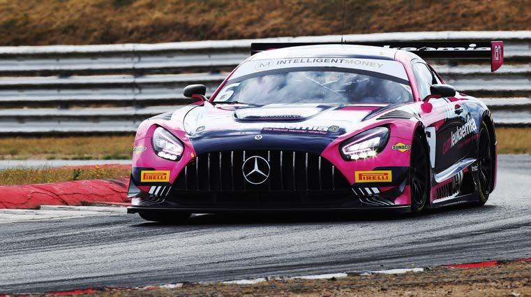
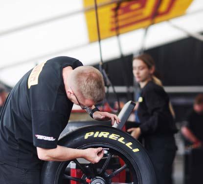
OCTOBER 2022 www.racecar-engineering.com 35 WE OPTIMIZEENGINEYOURKNOWIT!CONTACTUSFORFURTHERDETAILS E AUTOMOTIVE@RWBTEAM.EU. | T +31 (0)252-687 713 | RACEWINNINGBRANDS.EU YOUR PERFORMANCE PARTS CENTER STOCKLARGE DELIVERYFAST STAFFEXPERT Call: +44 (0) 1264 316470 Email: www.EvolutionMeasurement.comenquiries@evolutionmeasurement.com Discover The PressurEvolution Introducing the EvoScann® P16-D. The most advanced miniature true-differential 16 channel digital pressure scanner available. Ÿ 0.1% Full Scale Accuracy Ÿ Data output directly in engineering units Ÿ Lightweight - <45g (including 1m cable) Ÿ Small - dimensions: 50 x 32.4 x 10mm Ÿ True-differential measurement, shared static reference Ÿ Lightweight carbon fibre external construction Ÿ Integral microprocessor Ÿ CAN-FD output Get your competitive advantage now. Book a demonstration or request a quotation. EvoScann® P16-D


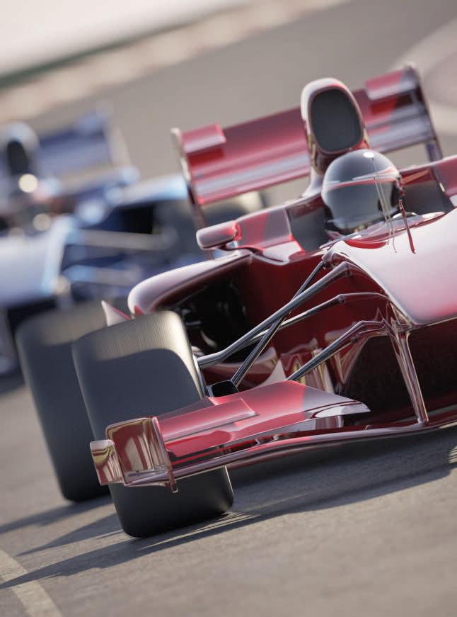

36 www.racecar-engineering.com
It’s important to keep an eye on the clock during a test day, so your car is ready to roll when needed and session time isn’t wasted
Eddie Ives, team boss, Elite Motorsport
OCTOBER 2022 forth and you really need to have a good understanding of everything; the damping, the suspension, the aero, the rake. The process is: first of all you’ve got to go out there and really define what’s stopping you from going quicker. Is it the rear of the car on corner entry? Is it traction coming out of the corner? Does it have understeer mid-corner? Whatever it is you’ve got to understand that. And then you’ve got to work with your engineers to understand what the next change to make is. And then you’ve got to go and quantify that and understand if it is actually heading in the right direction and it hasn’t affected anything else, and then you repeat and loop that process.’
‘A big part of testing is how you combat the challenges, how you react to different circumstances’
PRACTICAL ENGINEERING TESTING
You need to test with relevant fuel loads, while you also need to calculate the amount of petrol needed as part of your run plan
Testing times Not all drivers are so helpful when it comes to developing the car at a test though, as Steve Wills remembers from when he ran Kimi Raikkonen, then a car racing novice, in the 1999 Formula Ford Festival. ‘He went out and did 10 laps then came back in. We said to him: “What’s the car doing?” and he just said: “Well, seems all right”. So we asked him: “Are you happy?” and he just said: “Yeah, yeah.” And that was that. But it couldn’t have been right at that moment in time – it was impossible! It’s just that he drove around the problems. So, if it was understeering, or whatever, he’d simply drive around it, and that’s the sign of a very good racing driver.’ But not necessarily a good test driver. Then that’s the thing with drivers, they’re human and each will have different requirements and different levels of skill and experience. But those drivers who want to make a profession out of their racing do need to nail testing, as there will be little time on track for them to make the difference when they climb the ladder, or if they move into sportscars or GTs. ‘Post GB3, when you go into FIA F3, there’s not so much testing,’ says Ives. ‘And if you go the sportscar route, you don’t get half the opportunity to test, as there are less test days, mainly because it’s too expensive, but also if you go into GT cars and you’re sharing cars, all of a sudden the reality is the am drivers will want to spend all their test day in the car, and so you only go out for five laps in the morning, set a benchmark, and five laps at the end of the day.’ Of course, quite a lot of a driver’s work that was once part of a test day, the actual learning of a track for instance, can now be done on the sim. There’s not much, in fact, that cannot be simulated to some degree these days, whether it’s shaker rigs or the even more virtual world of CFD and DIL simulators. And yet, when all’s said and done, simulation can only take you so far. ‘We put the car on the 4-post rig and it cost two grand – though you also get a plate of sandwiches and a few cups of coffee at lunchtime,’ Wills says. ‘Then you put the car on the track and the guy can’t drive it. You end up slowly working back to what you had. Because the engineering principles don’t always tally with what is best in the real world.’ This is because however good a tweak might seem to a race engineer, it’s useless if the driver can’t live with it on track, whatever the numbers might say. If a driver can’t take the car to the limit, an engineer’s development idea counts for nothing. Often a session can count for nothing, too, thanks to red flags flying, oil being dropped and rain falling, but then that’s all part of the game. ‘You just have to play to what you’re given,’ says Ives. ‘You go with a run plan, but it always changes. Oil on the track, rain, it changes things, and it is part of the challenge of motorsport, being on busy test days and trying to make the most of it. But in reality all the teams are in the same boat. A big part of testing and real life motorsport is how you combat the challenges, how you diversify and react to different circumstances. Good people in this game can do that very well.’ Good people in this game also tend to enjoy that challenge. ‘You do a run plan every session; we’re going to do this many laps, we’re going to do this long a pit stop, we’re going to put this much fuel in and we’re going to come out on vapours at the end – and then someone puts their racecar in the gravel and the track is closed for 15 minutes,’ says Wynne. ‘You have lost seven laps, you put your new tyres on but the racecar weighs 25 kilos more than you wanted it to. But then that’s the best bit about the whole job of being a race engineer, thinking on your feet.’ Testing, then, can be as much a test of character as it is of machinery. But when it comes to succeeding in professional motorsport, it’s a test you need to pass.
OCTOBER 2022 www.racecar-engineering.com 37 a Baker Hughes business ApplicationsforOptimisedyou In conjunction with Druck’s Motorsport sensors, the instruments from Druck provide a complete test solution. To find out more head to our https://bit.ly/motorsportrace4website: Pit lane Testing • Tyre pressure measurement • Fuel & brake pressure testing • Turbo compression test • Engine sensor testing Wind tunnel Testing • Automated testing of pressure sensors • Pressure measurement of air flow. • Barometric pressure measurement Dyno-cell Testing • Sensors for engine pressure testing (oil, fuel, air intake & compression) • Barometric pressure measurement • Calibration of pressure & temperature test sensors CUSTOMFUELCELLSDESIGNED&MANUFACTURED BYATLFITTEDINFORMULAONEANDWRCCARS #ATLInside #ATLInside CUSTOMDESIGN HIGHPERFORMANCE SAFETYFUELCELLS CUSTOMFUELSYSTEMS UTILISINGDECADESOFMOTORSPORT KNOWLEDGE,ATLCANSUPPLYANFIA APPROVEDLIGHTWEIGHTFUELCELL WITHAFULLINTERNALSYSTEM HISTORICREMAKE RETAINTHEORIGINALLOOKOFYOUR TANKBYSENDINGUSASKETCH,3D CADMODEL,EXISTINGORRE-MADE CONTAINER CRASH RESISTANT, EXPLOSION SUPPRESSANT & EXTREMELY LIGHTWEIGHT


LimitedCustomsArtBlackatKmieciakJamesImages: AERODYNAMICS TOYOTA TS010
Between 1991 and 1993 the sportscar world witnessed some of the most extreme downforce figures ever seen, so it seemed like a nice idea to review some of the more significant changes trialled in the wind tunnel back then, and then compare the findings with our current CFD values. Baseline Model. Run 1 100% 787B CFD v 20% 91CV Toyota started with its 91CV wind tunnel model as its baseline. But as we don’t have an accurate model, the 1991 Le Mans winning Mazda 787B model, as used for a project by Mark Peters a few years ago, seemed a viable substitute. The 787B model came from scanning and scaling an insanely detailed 1/8th model from a well known manufacturer that had scanned the original car in the museum to get to this point, then sanity checking this against well documented 91CV measurements. Regulations and a similar design intent saw the two models equipped with a single, medium cambered profile, rear wing fixed on central, gearbox-mounted, stanchions sat behind a short tail section bodywork that covered the rear mounted powertrain and similarly styled ground effect tunnels. The 787B model also had a front mounted radiator as per the 91CV, while extra intakes and ducts on the 787B’s flanks were left open for initial analysis. In effect, the model matched similar cars in period for cooling, ground effect floor, front splitter, cockpit canopy, and a low rear wing, as seen on the Mercedes C9/11/291 and the Jaguar XJR9 through 12. Definitely a good representative baseline to start from, then, that would give us comparable, qualitative, results to work from. Starting with the baseline model comparisons, the ride height on the original 20 per cent tunnel tests saw front axle clearance at c.45mm and rear ride heights of 66mm (9mm and 13.2mm on the 20 per cent model) giving a minimum front splitter clearance of 40mm and a rake angle of 0.43 degrees. Due to limitations with our CFD package and the time available, coupled with the fact we have enclosed bodywork, we opted to remove the rotating wheels option as tested in the tunnel. With plenty of data on the effects of rotating wheels on
F
38 www.racecar-engineering.com OCTOBER CFD2022 machinetime
rom 1990 to 1993 the Toyota TS010 Group C car was put through an intensive aero development programme by Tony Southgate and Geoff Kingston in the Kings College 20 per cent and 35 per cent wind tunnels in London. In those three years the pair completed over 2000 runs, reviewing the full spectrum of body modifications from brake duct positioning to complete body design and wing placement, and in the process pushing downforce figures way higher than had previously been seen in any form of motorsport at that time (a process that will be examined in detail in a future issue).
Back in the high downforce Group C days of the early 1990s Toyota tried just about every tweak imaginable on its TS010 in the wind tunnel. But how do the numbers found then look in CFD now?
From the sheer amount of data sheets and photographs that has been provided to us, it was clear they investigated every available option the regulations would permit to ensure the 1993 TS010 was going to be capable of taking on the 1992 championship-winning Peugeot 905s at Le Mans. Even designs that had first come to light in the free-thinking world of Can-Am two decades previously were trialled again to see if any benefits could be sensibly achieved with new manufacturing technologies, and the better understanding of the aerodynamic interactions courtesy of modern wind tunnel testing.
Between 1991 and 1993 the Toyota TS010 was the subject of countless wind tunnel tests, with pretty much every conceivable aero configuration trialled
By JAMES KMIECIAK


Table 1:
Run 1: There is no model of the 91CV from which the TS010 was developed, so the similar Mazda 787B was used
Run1: While there were some differences the CFD results suggested the 787B model provides a good baseline for the study
The original 91CV model produced 5205lbsf downforce with 1227lbsf drag with a 34.8 per cent front axle load and, as stated at the time, ‘allowing for transmission losses of 8.75 per cent and a 620bhp engine [which] would produce approximately 190mph maximum speed, which is good enough for most sprint circuits’. This gave us our sanity check and anchor point. With scaling effects of the 20 per cent model having already been accounted for, we ran the Mazda 787B model at a regular wind tunnel benchmark of 100mph, or 44.4m/s. The model produced stable results, so we started from here then scaled again to produce matching 200mph data sets. For interest the values through a speed range of 50 to 200mph are included in Table.1
The Mazda model produced 5813lbsf with drag at 1157lbsf all at a balance split of 43.4 per cent front and 56.6 per cent rear. This gave it an aerodynamic efficiency, -L/D, with downforce (-ve lift) divided by drag of 5.025:1. When compared against the 20 per cent 91CV model at the same speed this shows 608lbsf more downforce and 70lbsf less drag. At closer to 45 per cent, the front balance on the 787B model was more desirable than the initial 91CV model at 34.8 per cent. We could be confident our Mazda would hug the apex kerbs of Tertre Rouge at Le Mans instead of drifting out towards the gravel traps and Armco like the initial 91CV models balance would infer. As for the top speed, at the entry to the first Mulsanne Chicane at Le Mans the Mazda 787B model would likely hit 192.1mph, compared to the expected 190mph calculated for the 91CV, if they were both provided with 620bhp powerplants and matching transmission and tyre drag losses.
Run 1: In CFD the Mazda version was better balanced than the original 91CV and a little quicker in a straight line too
As Tony Southgate stated when reviewing the Toyota 91C-V: ‘[1991 Group C Cars] are producing 5900lbsf downforce with 1370lbsf of drag split 39 per cent on front axle [minimum] at 200mph. This is with a rear flap angle of 17.5 degrees and a ¼-inch angle section [Gurney flap] fitted.’
OCTOBER 2022 www.racecar-engineering.com 39
Run 1 a sportscar style bodywork in CFD, this was factored into our results afterwards.
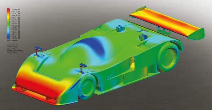
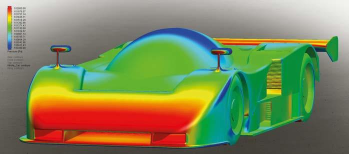
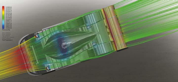
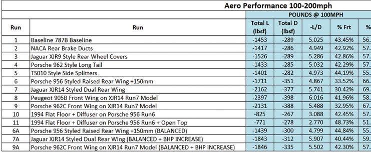
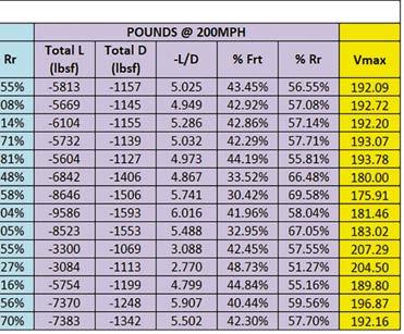

Our CFD analysis showed the wheel covers did not reduce drag as expected, in fact they increased it by 10lbsf over the open wheel version
AERODYNAMICS TOYOTA TS010
Run 3: Jaguar XJR9-style rear wheel covers were expected to reduce drag but the CFD analysis showed it increased by 10lbsf. On the other hand they also generated a very big increase in downforce, with no change in the aero balance
When asked why the these wheel covers were removed on the 1993 TS010, Geoff Kingston gave another insight into their fitment. ‘In Le Mans 1992 we had mixed
40 www.racecar-engineering.com OCTOBER 2022 Run 4 Run 2 Run 3
Noting that our CFD was only compared head on, the side winds that would have been experienced as the car went down the Mulsanne straight at high speeds may have shown a reduction in drag as the rear wheel arch would have seen less entrained airflow.
Given the model differences this happily suggests that we are stood in the same dugout of the required ballpark. Run 2 NACAs v snorkel brake ducts With a good representative baseline model produced it was time to trial a small but noticeable difference between the two models: rear brake duct intakes. The Mazda had snorkels that were fitted to the suspended hub assembly and poked through holes in the upper deck between the rear arches, similar to Jaguars of the same period. First runs of the 91CV/TS010 development model saw NACA style brake ducts in the same area, with Southgate commenting that these needed to be angled to be in-line with the incoming flow. As this likely affects the rear deck and rear wing aero performance it made sense to trial it. The results showed a reduction in downforce of 144lbsf at 200mph and a reduction in drag of 12lbsf, which produced a small increase in top speed of around 1mph. This meant downforce dropped to 5669lbsf, drag dropped to 1145lbsf and our efficiency, -L/D, reduced from 5.025:1 to 4.949:1 with a minor rearward change in balance of 0.5 per cent. An improvement in rear wing performance and slight shift rearwards made sense, but the significant loss from the main body was attributed to the simplified brake duct modelled from the NACA intake to the rear wheel. Fortunately, this was now our new baseline! Run 3 XJR9 wheel covers Noticeable by their absence on the 1993 car, the TS010 used Jaguar-esque rear wheel covers through 1992. Although used on WMs and Intrepids of the same era, these were consistently absent throughout the period of Group C on the successful cars of Porsche, Mazda, Mercedes and Peugeot. Initially it was assumed they reduced drag, but our CFD analysis showed the wheel cover did not reduce drag as expected, in fact they increased drag by 10lbsf over the open rear wheels to 1155lbsf. Downforce, on the other hand, jumped up by 435lbsf to 6104lbsf! That’s a huge chunk of downforce from a simple modification. This gave the car an -L/D of 5.286:1 with no change to balance.
Run2:The use of NACA brake ducts on the top of the rear bodywork resulted in a reduction in downforce and drag
Run 4: A Porsche 962C long tail-style extended rear deck integrating the rear wing and endplates was also evaluated
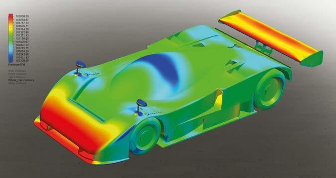
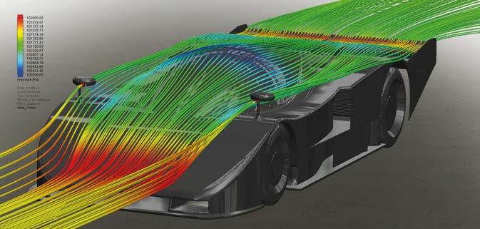
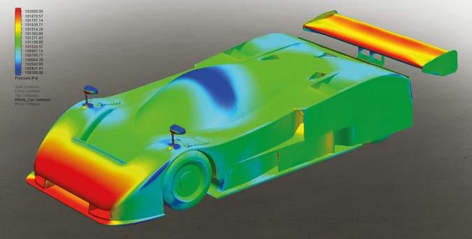
Run 5 TS010 side splitters
Run 6 Mercedes high rear wing Many of the runs undertaken on both the 20 per cent and 35 per cent wind tunnel were optimising rear wing profiles and positions. This project used a generic rear wing profile throughout the analysis and kept it at the same angle of attack without running a secondary flap or trailing edge Gurney flap to aid comparisons. As per the Mercedes C9/C11 and Porsche 962C, a high downforce sprint setting that raised the rear wing over 150mm from our Le Mans setting was trialled on the TS010. With Run 5: The ducting that was low down on the 787B’s side was removed, to bring the model more in line with the TS010, which had flat flanks and a side splitter. This area of the car was subjected to plenty of study in the tunnel
A minor oversight that needed correcting to bring us in-line with the TS010 was the removal of the 787B ducting low down on the car’s sides. The TS010 (and 91CV) had flat flanks and a side splitter that was adjusted for depth, undercut, angled and tapered on several of the wind tunnel runs back in 1991. Blanking this off and comparing this against our Run 2 model we see downforce reduced from 5669lbsf to 5604lbsf and an 18lbsf drop in drag to 1127lbsf, increasing top speed to 193.78mph, and moving balance forwards three per cent to 44.1 per cent with -L/D at 4.973:1. This area of the car would show greater changes in aerodynamic performance with the car running mid-corner with the airflow running along the sides. Sadly, we don’t have the time for that here.
Run 6 Run 6: The rear wing was raised 150mm over the Le Mans settings, in line with the Mercedes and Porsche in period Run 6: The raised rear wing was great for downforce, but not so good for drag, the car losing 14mph on the straight Run 6: The larger low pressure area right behind the racecar helped increase the work that was done by the floor
Run 5 weather that saw tyres running quite cool, in the warmer races I believe the team was starting to see overheating, So I think that’s why they came off for Le Mans ’93,’ he said. This may also explain why Jaguar had more and more NACA style ducts mounted in these cover panels throughout their use.
Run 4 962C long tail and integrated wing Following on from the early Group C Porsche domination with its 956 and 962 ‘lang heck’ (long tail) bodywork, the TS010 also trialled an extended rear deck that integrated the rear wing and end plates. When compared with the uncovered rear wheel model of Run 2 we see this set up produced a relatively small downforce gain to 5732lbsf with a negligible drop in drag of 6lbsf to 1139lbsf, retaining similar top speed and balance. The change in downforce produced an improved -L/D of 5.032:1. If this is taken as the 1988 962C performance and Run 3 as the XJR-9, we can see that with matching balance and a -L/D of 5.286:1, the Jaguar would have almost 100lbsf less drag for the same downforce. Helpful for the sprints between the chicanes at Le Mans.
OCTOBER 2022 www.racecar-engineering.com 41
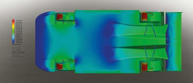
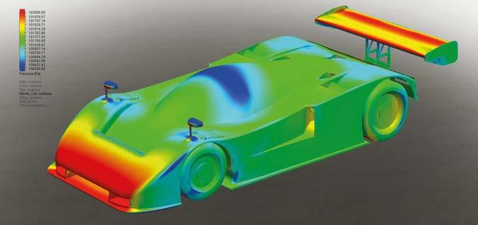
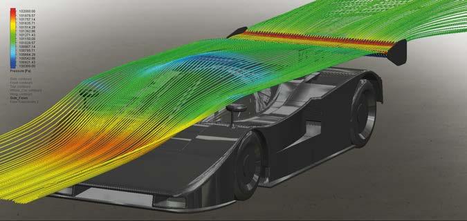
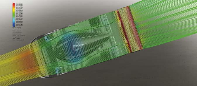
OCTOBER 2022 Run 7the wing in clean air downforce jumped by 1200lbsf at 200mph, with an increase over the front and rear floor occurring courtesy of a larger low pressure area behind the car helping to pull more air under it. Of course, all of this is at the cost of a relatively large increase in drag; a 279lbsf increase, in fact, which reduces the top speed by almost 14mph to a mere 180mph. At 33.5 per cent front bias balance was 10 per cent further rearwards than ideal. If we drop the rear wing angle to get the balance back to 44.8 per cent we would expect to see -L/D reduce from 4.867:1 to around 4.799:1, but top speed improves by almost 10mph. Run 7 XJR14 biplane rear wings
Biplane rear wing fitted to the TS010. The lower beam wing has the job of working the floor, the upper wing controls aero balance
Run 7: A Jaguar XJR14-style biplane rear wing was fitted and downforce increased hugely, but aero balance was hit Peugeot was the dominant team in 1992 so it made sense to trial its philosophy of putting the front wing in front of the car’s nose
42 www.racecar-engineering.com
The big jump for the TS010, and for Group C racing in general, came in 1991 when the Jaguar XJR14 of TWR showed up with the biplane rear wing. This gave the lower rear beam wing the sole job of driving the floor while a separate, shorter chord, upper rear wing dealt with controlling the racecar’s aerodynamic balance. In our model we have simply added a similar profile, chord and span rear wing as we have used for the lower beam wing, but some 300mm above it. As expected, downforce sky-rockets off the chart at the detriment to aero balance. The excessively large upper wing helped produce 8646lbsf downforce, almost 3000lbsf more than a single lower beam wing only. Compared to the car as seen in Run 5, an increase of almost 400lbsf of drag reduces top speed to 175.9mph, but with a drastically improved -L/D of 5.741:1 In his reports to Toyota, Southgate mentioned that the car needed over 720bhp to be capable of 200mph at Le Mans. So, modifying our available horsepower to allow for this, then trimming the upper and lower wings to get our c.40 per cent balance back, we end up with a more realistic comparison between the original low rear wing and new dual rear wing designs. Downforce is still massive, at 7370lbsf, with the increased low pressure area behind the car improving the splitter, floor and
In his reports to Toyota Tony Southgate mentioned that the car needed over 720bhp to be capable of 200mph at Le Mans
Run 7: With balance restored, increased low pressure behind the car improved splitter, floor and tunnel downforce
AERODYNAMICS TOYOTA TS010
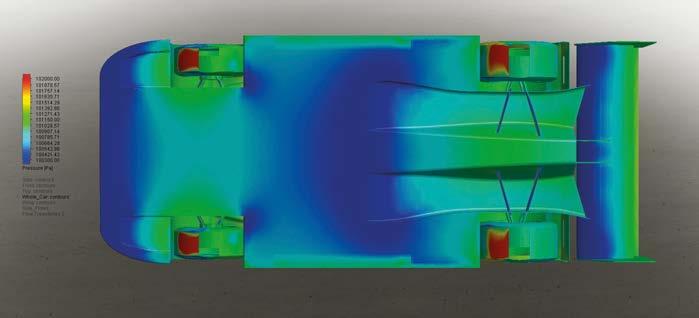
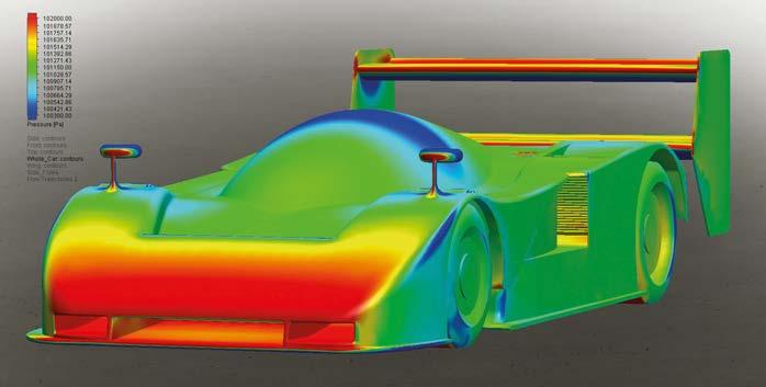
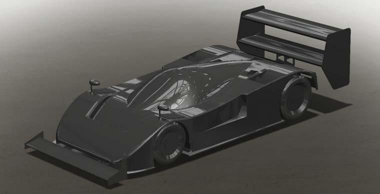
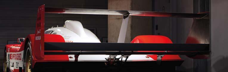
Run 8: The Formula 1 style front wing produced a staggering 9586lbsf of downforce. The best seen during this study
OCTOBER 2022 www.racecar-engineering.com 43
Run 8 tunnel downforce, allowing the balance to sit at 40.4 per cent and dropping drag to 1248lbsf. As Kingston said: ‘(-L/D) increased by a factor of one overnight,’ which is pretty much seen here with our Run 5 -L/D comparison going from 4.973:1 to 5.907:1. With the increased power we can see a similar top speed of 197mph, against 194mph. Comparing this with the original 20 per cent TS010 model figures, and noting the model differences, the TS010 model had 7856lbsf downforce with 1400lbsf drag for a 5.611:1 -L/D, with similar balance. Run 8 Wing in front of nose The Peugeot 905B dominated the 1992 season and was the car to beat at Le Mans. The 905B latterly had a dual element wing mounted Formula 1-style in front of the car. So we trialled a 300mm chord, medium camber, full span single element wing in front of our existing Run 7 bi-plane model. This modification produced the biggest downforce seen. A staggering 9586lbsf (that’s over four tons!) of downforce for 1593lbsf of drag, giving an efficiency of 6.016:1 with a balance of 41.9 per cent. Even with the increased bhp the car would have only been capable of an estimated 181mph. But if we trimmed it out and kept the same -L/D to reach 197mph, as per the XJR14 based model, we would have seen figures of 7508lbsf downforce and 1248lbsf drag. That’s 138lbsf more for the same drag and balance. This didn’t match up with the Peugeot 905B model Toyota tested at 20 per cent back in period, though, which had somewhere in the region of 6407lbsf downforce, 1478lbsf drag with an -L/D of 4.334:1 and around 44.8 per cent front balance. The nose being shorter, radiators being shifted to the car’s sides, and the possibility that the models in the Dome tunnel were still built to an unsuitable level, as mentioned by Southgate in his notes, could easily account for this.
Run 8: A 300mm chord, medium-camber full span single element front wing generated spectacular downforce figures
Run 8: While the drag figures also increased, trimming out the car would still have shown a big improvement
The Peugeot front wing
Run 8: Working in conjunction with the biplane rear wing, the power of the F1-style front wing is clear in this image
1593lbsfofstaggeringdownforceproducedmodificationthebiggestseen,a9586lbsfdownforceforofdrag
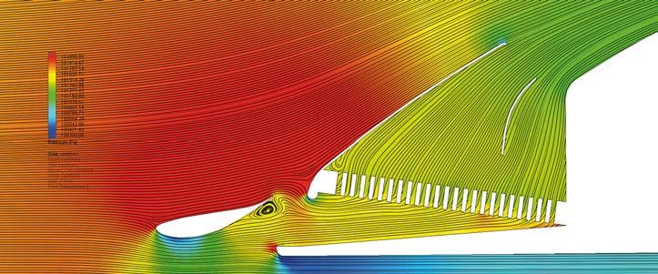
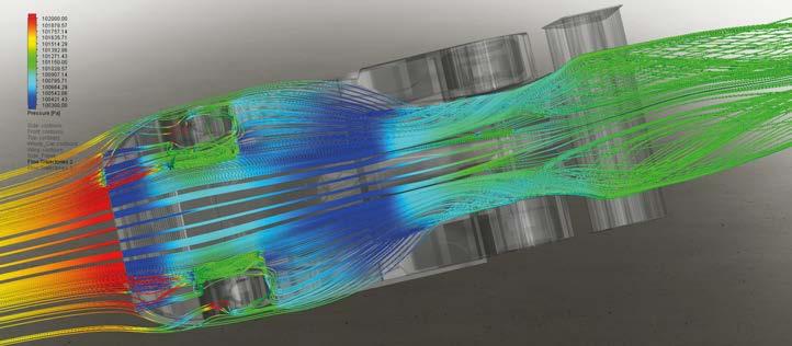
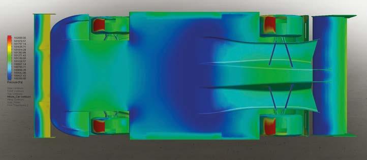
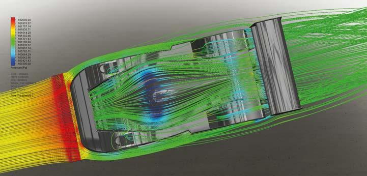
The last big downforce ground effect pole position was gained by Peugeot with a 3:24.94 in 1993, a year later a Courage C32 could only manage 3:51.05, nearly 30 seconds slower
Run 10 Flat floor appraisal for 1994 LM GT1 regulations February 1993 saw the last runs undertaken in the 35 per cent tunnel for the TS010 and conversations between Toyota and Southgate turned towards a potential move into the new-for-1994 LM GT1 class. With this in mind Kingston trialled a flat floor on the model to turn the Group C TS010 into a potential road going GT car. This flat floor was a huge step away from tunnels. It lost 80 per cent of the car’s downforce and reduced the -L/D from 6.420:1 to 1.620:1 immediately. With the model set up the same as in Run 6, with a single raised wing as became the regulated norm from 1994 onwards, the tunnels were removed and a flat floor with period style diffuser fitted instead. With the inclusion of the diffuser the drop in -L/D wasn’t as drastic as recorded in the tunnel but still dropped from 4.799:1 to 3.088:1, so down by a factor of over 1.5. Downforce lost 2454lbsf (that’s over a ton!) and drag reduced markedly, too, thanks to the swirling vortices and low pressure zones of the tunnels being exchanged for the benign flat floor and shallow diffuser. But with drag down to 1069lbsf from 1199lbsf, and balance at 42.4per cent, the top speed was given a 23mph boost from 184mph to over 207mph. The downside of the racecar’s loss in downforce was lower corner exit speeds, which subsequently reduced the top speeds further, which in turn affected the overall lap time. A power reduction also slowed the racecars down. In 1993 the last big downforce ground effect pole position was gained by Peugeot with a 3:24.94, a year later a Courage C32 could only manage 3:51.05, nearly 30 seconds slower, a pace difference that was confirmed in the race. It took Mercedes in 1998, with its CLR, to show chassis and engine development had started to catch up, with a 3:35.54 pole lap. Yet that was still 10 seconds off the Peugeot’s time from five years before.
AERODYNAMICS TOYOTA TS010
Toyota evaluated the possibilities of developing the TS010 for the new LM GT1 of 1994, effectively making a street legal Group C car Run 9: This mod proved disappointing with the over-body front wing producing extra drag while lowering downforce Run 9: The front wing was shortened and mounted on endplates over the nose, as seen on Porsche 962Cs in 1984
44 www.racecar-engineering.com OCTOBER 2022 Run 9Run 9 Front wing above body As a sanity check, and as was also trialled on the TS010 wind tunnel model, the same front wing as used in Run 8 was shortened and mounted on endplates over the front nose and between the lights, as seen on some Porsche 962Cs in 1984. The corrected values with our desired front balance of 42.3 per cent brought -L/D down from 6.016:1 to 5.502:1 as the over body front wing produced 94lbsf of drag and lowered the downforce to 7383lbsf. We can clearly see why the design team at Toyota didn’t revisit this set-up again.
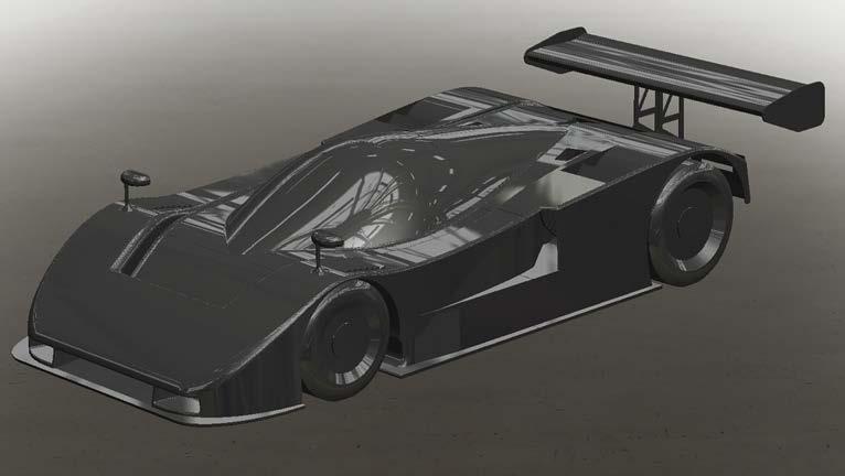
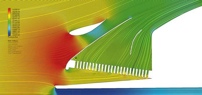

OCTOBER 2022 www.racecar-engineering.com 45 Individual solutions You needa special solutionor a individual adjustment of our conproducts?standardSimplytactus.Sensors for tyre and braking systems Sensors for exhaust gas systems Sensors for fluids Display devices and transmitters ThermocouplesAccessories Therma Thermofühler GmbH Schreiner weg 8 51789 Lindlar Germany .Tel.:+492266 8026. www.therma-motorspor t.de The sophisticated Specialist in Thermo Sensor Technology for Motorsports. isTemperatureourBusiness.


Racecar’s thanks Geoff Kingston for his time, and also Black Art Customs Ltd for all the models and data it has produced. Run 11 Run 11. The open-topped car from below. This was the most aerodynamically inefficient design in the entire study Run 11: The final CFD analysis looked at where LM prototype design went in later years, with open cockpit racecars Run 11: Large cockpit orifice and the chunky roll hoop means the airstream to the rear wing is massively disrupted
AERODYNAMICS TOYOTA TS010
Reflections
Toyota went on to produce the iconic TS020 GT-One for the 1999 Le Mans, which clearly continued where the aero development of the TS010 left off Run 10 Run 10: The tunnels were removed and a flat floor with period style diffuser fitted instead. The results were not good
The final analysis is close to what became the top LMP class at Le Mans for the next few decades, an open top version of the Run 10 set-up, with a large roll hoop. With the disruption of the cockpit, and particularly the roll hoop, reducing rear wing performance, we find front balance shifted forwards by around four per cent to 48.7 per cent. The rear wing lost downforce, dropping it by 216lbsf to 3084lbsf. Drag increased by 40lbsf, meaning top speed dropped to 204.5mph and efficiency hit its worst recorded value of the entire project, 2.770:1.
Toyota never ran an open top car going forward, unlike Audi, which after its initial coupe, successfully raced the open top R8 for almost a decade in the LMP900 class all over the world. New aero regulations producing standardised floors and diffusers still favoured a coupe at Le Mans, with Bentley winning in 2003, before the ACO/ FIA requested all cars in LMP1 should become hardtops almost 10 years later, to make the cars safer and keep manufacturers’ marketeers happy with cars that slightly resembled those on the forecourts. During this period Toyota produced the iconic TS020 Toyota GT-One for the 1999 Le Mans, which clearly continued where the aero development of the TS010 left off, but the company still failed to win the great race. In fact, it had to wait until 2018, when its TS050 Hybrid crossed the line first to finally win at Le Mans. But with the FIA Hypercar class promoting the integration of free aerodynamic design, and two-seater GT style chassis, is it at all surprising that Toyota has since become the benchmark for the pinnacle of World Sportscar racing?
46 www.racecar-engineering.com OCTOBER 2022 Run 11: 1994 Joest-Porsche
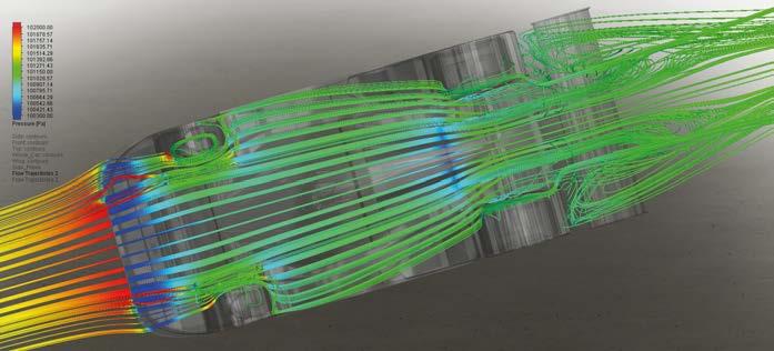
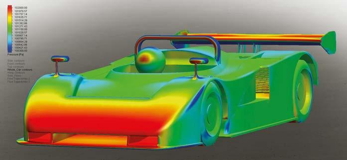
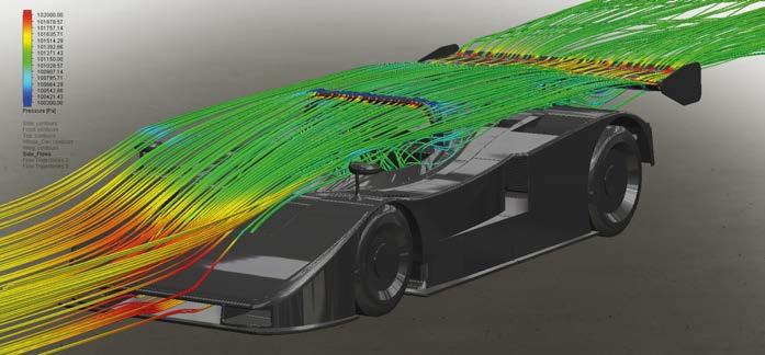
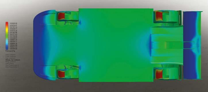
OCTOBER 2022 www.racecar-engineering.com 47 Our specialism is in the detail of race engineering – the hard to source simple things that can make or break a deadline. Check online, call us or call in. NAS BOLTS AN BOLTS K NUTS ANCHOR NUTS AN NUTS & WASHERS MS WASHERS PIP PINS AIRCRAFT MISC CAMLOC DZUS TRIDAIR ROD ENDS SPHERICAL BEARINGS UNIVERSAL JOINTS BOLTS FULL NUTS HALF NUTS NYLOCS OTHER NUTS T&C WASHERS SCHNORR PENNY PLAIN COPPER SEALING DOWTY SEALS WING WASHERS OTHER WASHERS ALI FASTENERS RIVETS RIVNUTS LAY-UP PINS KEENSERTS TIMESERTS HELICOIL OVER CENTRE LATCHES OTHER LATCHES/HOOKS FASTENERS & PINS ADVANCE ADHESIVE TAPES HELICOPTER TAPE DOUBLE SIDED TAPE SELF ADHESIVE FOAM VELCRO TESA TAPE TYRAPS MOUNTING BASES GEAR OILS LUBRICANTS & SYRINGES ADHESIVES CLEANERS SUBSTRATE ACCESSORIES DOW CORNING WURTH LOCTITE FLAWTEK BRAKE CLEANER RAINEX RAIN/FOG BRAKE PADS CLUTCH OIL FILTERS EXHAUST IGNITION GASKETS FFORD BRAKE BIAS BRAKE FLUID BRAKE TEMPERATURE GIRLING & ALCON MASTER CYLINDERS PIPE, TOOLS & CONNECTORS BRAKE DUCTING SILICON WATER HOSES The componentspartsshopone-stopforand SILVERSTONE CIRCUIT 01327 857822 WWW.TRIDENTRACING.CO.UK Supplying the parts that others cannot reach Check our website. Your search is nearly over.


By LAWRENCE BUTCHER Electric motorsport, probably more than any other genre of racing, is all about incremental gains, particularly in terms of powertrain development.
Common to ICE and electric machines are mechanical losses, though they are far less significant in an electric motor, but whereas in an ICE there are losses in the combustion system, in a motor there are electrical losses. Furthermore, both ICE and electric motor losses tend to manifest themselves as heat,
Both ICE and electric motor losses tend to themselvesmanifestasheat
48 www.racecar-engineering.com OCTOBER 2022 Efficiency drive
With the growth in EV racing the quest to improve e ciency and reduce losses in electric motors has gained pace in recent years, with new technologies and wonder materials emerging. Racecar assesses their impact
Thin laminations create a smaller conduction path for the currents than if thicker laminations are employed. With the current being proportional to the area of the loop, reducing the area reduces the current that is able to flow. Some of these laminations can be incredibly thin, 0.127mm thickness for example, and they are rolled from non-grain orientated electrical steels (NGOES)
Electrical losses
To briefly recap the types of motor most found in racing applications, at one end of the scale are the very high output, but relatively crude DC units, like those found in electric drag cars. These have excellent power characteristics but are hard to control and not suitable for applications that require energy recovery. Advanced hybrid and electric race vehicles tend to use AC (alternating current) motors and amongst the various subsets of AC motors, synchronous motors are currently seen as the best solution. In most applications, this means the use of permanent magnet synchronous motors (PMSMs), of either the axial or radial flux type. The majority of PMSMs utilise permanent magnets mounted on the surface of the rotor. This makes the motor appear magnetically ‘round’, and the motor torque is the result of the reactive force between the magnets on the rotor and the electromagnets of the stator. However, some PMSMs have magnets that are buried inside of the rotor structure, logically referred to as Interior Permanent Magnet (IPM) motors.
Take Formula E, where even in the first season of competition efficiency of the spec McLaren supplied motor and inverter package was around 96 per cent, a fair figure today would be somewhere between 98-99 per cent efficient. But however small the improvements, across the board – be it in WEC, F1 or FE – manufacturers have been chasing electrical efficiency gains from motors, inverters and battery systems. It is the first of these that we will focus on here.
Brandauer TECHNOLOGY ELECTRIC MOTORS
An electric powertrain must be considered in terms of the motor and controller when thinking of efficiency (and where used, the transmission). Each element is closely linked, and gains made in one area can easily be cancelled out if another part of the chain has excessive losses. Similarly, it is impossible to create a highly efficient motor without a suitably capable control system (just as an F1 engine would be useless without its ECUs).

OCTOBER 2022 www.racecar-engineering.com 49 The arrangement of the copper windings is key to the performance of the electromagnet, as the pattern determines the direction of the electromagnetic field
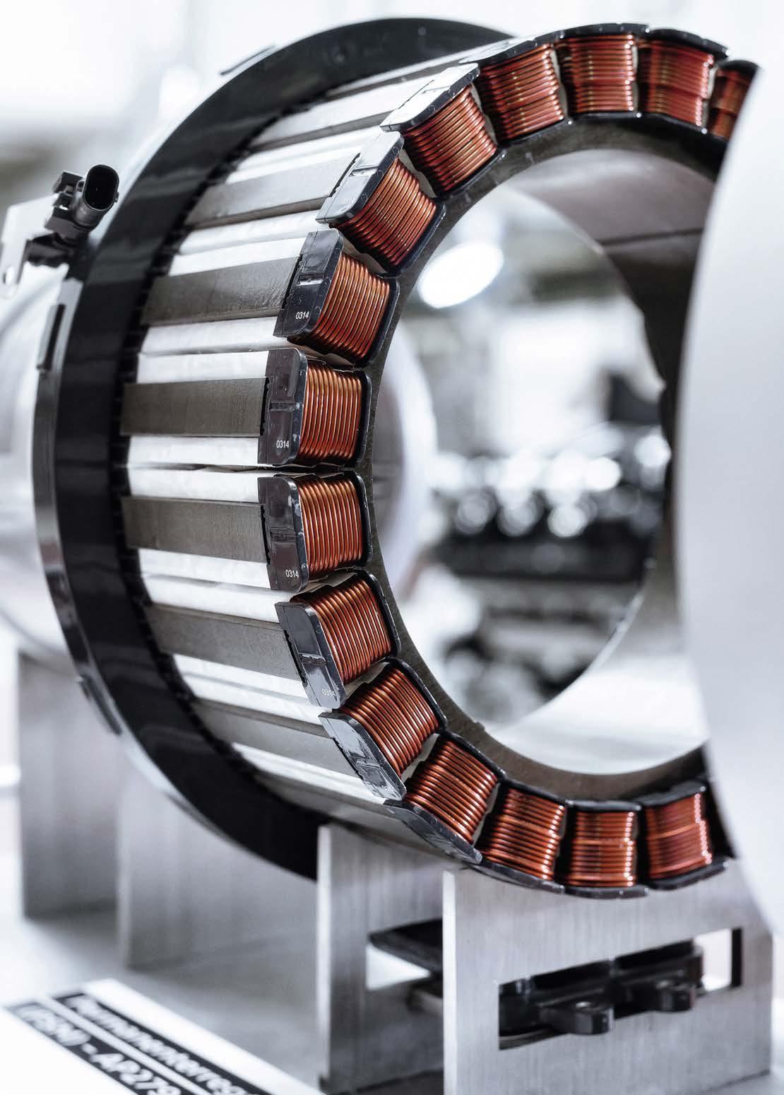
50 www.racecar-engineering.com OCTOBER 2022 which must be managed, a subject which we will be returning to later. Motor losses can be broken down into iron or core losses, and copper or ohmic losses, each with its own set of characteristics, and both of which contribute to a reduction in efficiency. Typically, many of the phenomena that cause losses also increase in severity when one ups the power of a motor. Starting with iron losses, normally shown as W/kg, these are comprised of eddy currents and hysteresis. Eddy currents, much like their name suggests, are currents that swirl like eddies in a stream. They run perpendicular to the magnetic field of a stationary conductor (in this case the stator) and are induced by changing magnetic fields in a closed loop (according to Lenz’s law). The problem is that as motor speed increases, so too do eddy current losses which are proportional to the square of the electrical frequency of the motor. With the trend towards ever faster and more compact motors (led by F1 and Formula E) iron losses are therefore a major consideration for motor designers. One of the main routes to reducing eddy current losses in the stator is through a TECHNOLOGY ELECTRIC MOTORS
An axial flux e-motor with an integrated inverter unit. In this type of electric motor the gap between the rotor and stator, or rather the flux between the two, is parallel to the axis of rotation
Each element of an electric powertrain is closely linked and gains made in one area can easily be cancelled out if another part of the chain has excessive losses
Nearly every contemporary high-performance motor features very thin steel lamination, which forms the stator stack. These are separated by an insulation layer which also needs to be kept to a minimum, while still allowing for thermal conductivity
MastersLaser Equipmake
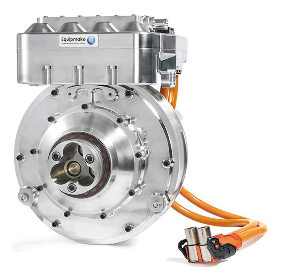

Moving up another step, for ultimate power density, high-induction, low loss cobalt alloys are favoured. For example, German firm Vacuumschmelze has long supplied its Vacoflux and Vacodur, 49 per cent cobalt-iron alloys into high-end racing. With exceptionally high saturation polarisation of 2.3T, they far outperform even the best silicon-steels, albeit at high cost. To make such alloys more accessible, the company did release its Vacoflux X1 material in 2019, with a 17 per cent cobalt content. It claims that, compared to a motor using grade 20 NGOES, torque output can be increased by up to 12.5 per cent at a cost far closer to regular electrical steel than the 49 per cent cobalt alloys. Moving away from laminations, one of the latest developments in terms of stator materials are soft magnetic composites (SMCs) which have the potential to replace
OCTOBER 2022 www.racecar-engineering.com 51 combination of materials engineering and construction. Nearly every (but not all, see below) contemporary high-performance motor features very thin steel laminations which form the stator stack, each separated by an insulation layer. Thin laminations create a smaller conduction path for the currents than if thicker laminations are employed, with current being proportional to the area of the loop, reducing the area reduces the current that can flow. With the losses being proportional to the square of the current, even relatively small drops in current can net useful gains in efficiency. In the past, a thin lamination was considered to be in the region of 0.5mm, however, advances in manufacturing techniques have seen much thinner laminations become available. For example, Arnold Magnetics produces its Arnon 5 and 7 laminations at 0.127mm and 0.178mm respectively. These are rolled from non-grain orientated electrical steels (NGOES), which are ideal for motor use. However, it can also supply grain oriented electrical steels, more commonly used in transformers (which have different magnetic requirements) down to 0.025mm thickness. To put this into perspective, the Formula 1 regulations limit laminate to a minimum of 0.05mm in the MGU-K, though the MGU-H is not limited. According to Arnold, a switch from a traditional 29 gauge (0.34mm) laminate to a 0.127mm production, can net in excess of a 60 per cent reduction in iron losses. One issue with using exceptionally thin laminations is that the thinner the sheet, the harder it is to reliably stamp out the stator laminates. Factor in the ever-increasing complexity of stator design, coupled with the challenges of reliably joining (either mechanically or via bonding) the individual laminations together, and it is clear why the very thinnest materials are the preserve of bespoke, high-value, low volume motors where ultimate efficiency is required.
High resistance
Another means of reducing eddy currents in the stator is to use high resistivity steels, which will tend to be referred to as silicon or electrical steels and have low hysteresis. It used to be that these steels had the disadvantage of a low saturation flux density. In practice this means a large and heavy stator was needed to achieve the same magnetic field as a material with a higher saturation flux density. Fortunately, developments over the past decade have seen new materials arrive on the market that have both high resistivity and good flux density.
Equipmake
The permanent magnet radial flux motor is the choice for many motorsport applications. This APM 120R is an interior permanent magnet motor with Samarium cobalt magnets
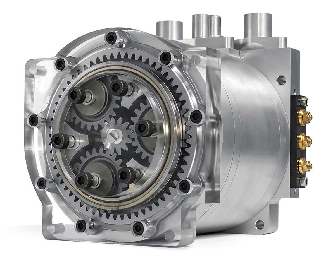
OCTOBER 2022 steel laminations in many motor applications.
Meanwhile, frequency dependent losses revolve around a phenomenon called skin effect, whereby the effective diameter of a wire is reduced as the frequency of an alternating current increases. As the frequency goes up, the current flow moves to the surface of a wire, increasing the resistance and thus temperature (which in turns increases resistance further).
‘We have materials that do enable high insulation with good conductivity.thermalSome of those are next-generation and are still in development’ Carlo Fiorella, global automotive manager, DuPont Efficiency map of an interior permanent magnet motor. With these the magnets are positioned inside the rotor structure
All of the materials listed above also help reduce hysteresis losses. These are caused by the magnetisation and demagnetisation process within a motor core as current flow changes direction. As the magnetising force (current) increases so too does the magnetic flux. However, as the magnetising force (current) is decreased, the magnetic flux doesn’t decrease at the same rate, but less gradually. Therefore, when the magnetising force reaches zero, the flux density still has a positive value. In order for the flux density to reach zero, the magnetising force must be applied in the negative direction.
52 www.racecar-engineering.com
SMCs are created using magnetic powder with an electrically resistive coating, which can be formed into complex 3D shapes using conventional powder metallurgy techniques. In addition to facilitating advanced magnetic designs, the insulating coating of the powder grains contains eddy currents within each grain of material, greatly reducing core losses at high frequencies (SMCs come into their own above 400Hz). There are some challenges when it comes to processing these materials, though. For example, finished parts must be heat treated to remove micro stresses after the compaction process. However, because the insulation material degrades at a lower temperature than iron (the base powder) anneals at, it is hard to fully remove all stresses.
Hysteresis losses
Copper losses Cooper or ohmic losses occur predominantly within the stator windings of a PMSM, and can be broadly split into frequency dependent and frequency independent losses. These losses occur on the basis of I2R, where losses in Watts are equal to the current squared times the resistance of the wire. The key to lowering these is reducing the resistance in the winding wires.
Equipmake
It is worth noting that it is not only the magnetic material in the stator core that must be considered. The insulation between the individual laminations also needs to be kept to a minimum, while ensuring proper insulation is provided, and also allowing for thermal conductivity. One favoured material for stator insulation is Nomex. While better known in racing for its use in fireproof equipment and honeycomb material for composites, Nomex paper is a widely used insulator. According to its manufacturer, DuPont, 80 per cent of BEVs utilise it in their traction motors, with the highest performance commercially available grade being Nomex 464 Lam, which is a lightweight, flexible paper insulation which can be supplied down to 0.05mm thickness.
The relationship between the magnetising force and the flux density are represented on a hysteresis curve, or loop. The area of the hysteresis loop (rather like the area under the curve for an engine) shows the energy required to complete a full cycle of magnetising and de-magnetising, the greater the area of the loop, the higher the losses. ‘Soft’ magnetic materials such as those detailed have a small area hysteresis loop.
DuPont is in fact a partner of the Alpine Renault F1 team, and Carlo Fiorella, global automotive manager at DuPont, says that it uses Formula 1 as a test bed for its insulation materials, making them lighter, stronger and with better thermal conductivity.
Frequency independent losses relate to the cross-sectional area, length and material of the stator windings, as well as their temperature. Pivotal to reducing the resistance of the windings for a given motor size (and increasing its torque density) is
maximising the fill factor. This is the reason why most traction motors now rely on hairpin windings, where rectangular rather than round wire is used. There are a host of other developments related to stator fill currently underway; for example, additive manufactured windings that can be created in forms impossible to achieve by winding.
Taking this last factor, generally, thermal conductivity and electrical insulation tend to work against each other. So how can these seemingly mutually exclusive properties be combined? This edges toward the territory of confidential IP, but Fiorella does tell us: ‘We have materials that do enable high insulation with good thermal conductivity. Some of those are newer next-generation ones that are still in development. But it is a great area of research, and we are always looking for ways to increase the thermal performance without decreasing safety.’
The solution is to use smaller diameter wires, but this is only effective up to a point, as the creation of eddy currents in wires adjacent to one another alters the distribution of current flowing through each wire, concentrating the current in areas of the conductor furthest away from adjacent wires
The great advantage of these is that they have isotropic magnetic properties, which allows for more complex magnetic design concepts than are possible with steel laminates, which have 2D magnetic properties.
TECHNOLOGY ELECTRIC MOTORS
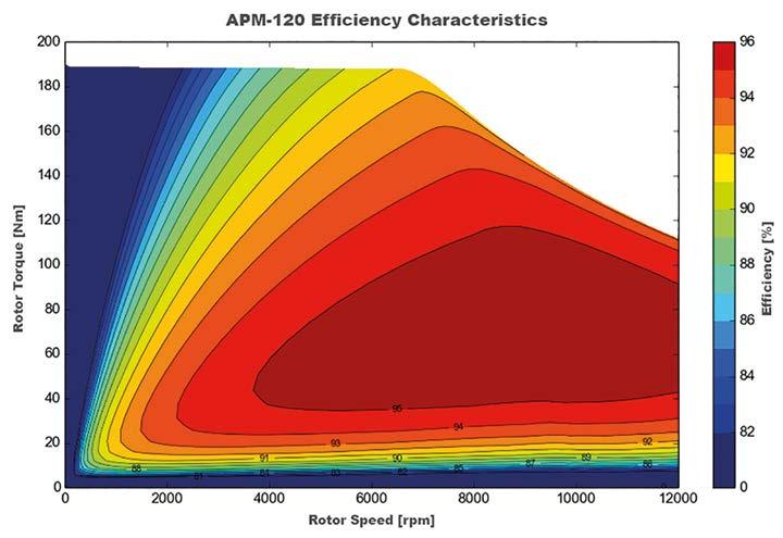
Experience the advantage of outstanding performance.
The engineers of the world’s best performing electric motors have evolved. Helix now makes ultimate power density accessible through scalable core technology and volume production facilities. On the road and track, at sea, in the air and in a multitude of industrial applications, Helix electric power is the future. Find out more at ehelix.com


It’s worth noting that there are also some circumstances where absolutely maximising fill factor may not be the route to optimum efficiency. For example, a particular stator design may be very good for cooling, but at the expense of copper fill, however, the latter is more than cancelled out by the reduction in losses the cooling provides.
54 www.racecar-engineering.com
TECHNOLOGY ELECTRIC MOTORS
In addition to good electrical design, effective cooling is vital to reducing copper losses in a motor. Most motors in a motorsport context will feature liquid cooling of one form or another, either direct cooling of the stator using dielectric fluid or, more commonly, the use of a cooling jacket around the stator, which interfaces using a cold plate. With the latter approach, one of the most important elements to consider is the interface between the stator and the cold plate. Maximising the thermal conductivity in this area is what produces efficient cooling. For example, if the contact between the windings and the plate is poor, or the cooling efficiency between the windings and the stator core is reduced, losses will increase. Therefore, elements such as the surface flatness of both the core and the cooling plates have a greater impact on cooling than the coolant flow within the cold plate.
SteelTata
This article gives an introduction to some of the factors that drive motor efficiency and a few recent developments that have helped engineers reduce losses. But there are, of
Changing the shape of the stator slots affects the magnetic path around them. This lamination steel is for the 200 to 2500Hz frequency range
OCTOBER 2022 with current flowing in the same direction. This is known as the proximity effect and can have a significant impact on resistance; it is a careful balancing act to find the best ratio of conductor thickness and distribution.
One of the most important elements to consider is the interface between the stator and the cold plate
The insulation material that encases the stator windings also plays an important role in cooling efficiency, with many motors using an insulating varnish. This has been an area of considerable development in recent years and single, double and triple coated wires are available. Triple coated wires are supposed to eliminate any pinholes in the insulation, which increases resistance to corona discharge (ionisation of air surrounding the wire). However, the thicker the coating, the lower the thermal conductivity, hence the development of varnishes that can be applied in a thin, pinhole free coat and provide good corona resistance with high thermal conductivity. Additionally, the thicker the insulation, the less space there is for wire, reducing fill factor, so the higher the resistance for a given current and the greater the temperate increase under load.
Complex matters
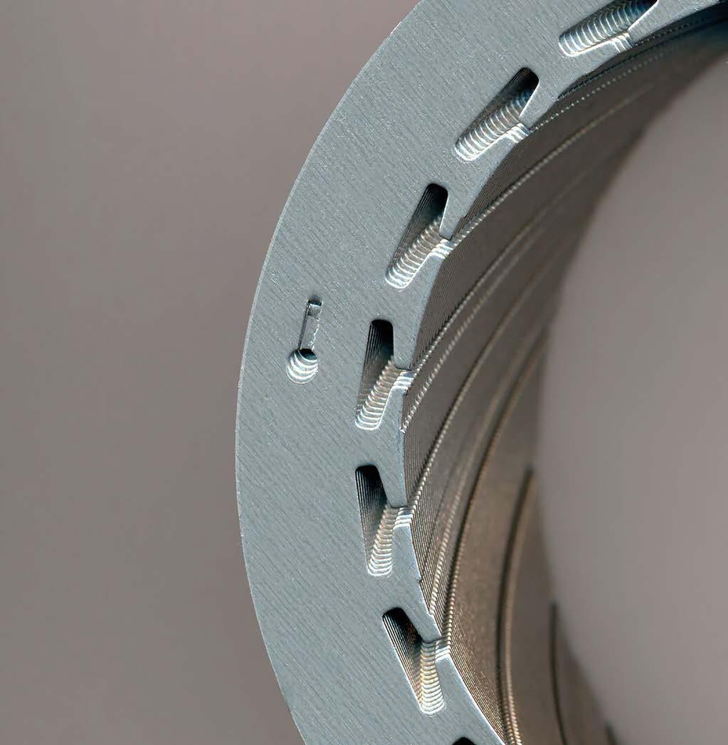
VISIT www.chelseamagazines.com/CRCE1022 CALL US ON +44 (0) 1858 438 442 and quote code CRCE1022 NB: *Free postage UK only. **Prices and discounts based on our annual UK rate of £84 / US rate of US$109.95 If for any reason you’re not happy with your subscription, you may cancel within 14 days of placing your order. Great savings when you subscribe Order your subscription TODAY 12 issues from just £49.95 – SAVING 40% (UK delivery)* USD $109.95 / RoW £79.95 / AUD $159.95 / Europe €84.95* archivetoFREEPLUSaccessthedigital–over100backissues! £34OVERSAVE**othefullprice


In YASA’s yokeless axial flux motor the flux jumps from the stator tooth to the magnets and back to the next stator tooth. Advantages of this design are the ability to have the flux interact with the two sets of magnets, thus significantly increasing the power density of the design –meaning less weight, less current, fewer losses, and more power
MotorsYASA
All these factors and many, many more have to be considered by engineers designing motors for racing use. It would be fair to say that the exceptional performance and efficiency of current machines is down to a combination of innovative thinking, materials development and advances in modelling capabilities that allow for high levels of refinement in both mechanical and electromagnetic design of motors.
The use of different winding designs can also decrease back EMF, with distributed (where the windings are distributed across the air gap of the motor) generally proving to be more efficient than concentrated windings (where each winding only goes around a single slot in the motor). As ever, there is a ‘however’, and in this case it is that well designed concentrated windings can also have low back EMF. Then there are losses that are related to the rotor’s magnetic design, and even the sleeve used to constrain the magnets on an PMSM. For example, if the sleeve is conductive, this creates a distortion in the magnetic flux and causes eddy currents. The use of a non-conductive sleeve removes these losses. But there is once again a caveat here, if for example an Inconel sleeve is used overall rotor losses can actually be lower due to it shielding the rotor. To achieve a similar level of performance with a non-conductive sleeve requires the use of laminated magnets, which have lower losses at the cost of a small amount of torque output (for a given rotor size).
TECHNOLOGY ELECTRIC MOTORS
56 www.racecar-engineering.com OCTOBER 2022 course, a whole host of other mechanisms at work that create losses. For example, PMSMs inherently suffer from a high level of ‘back’ EMF (electro motive force), which is a side effect of a magnet spinning within a stator. With a permanent magnet, the back EMF is proportional to motor speed, so once a motor reaches a certain speed, the back EMF will be such that it cancels out the available motor supply voltage, effectively limiting the maximum speed of a motor. This can be countered by ‘field weakening’ the motor, a process that injects extra currents into the winding, reducing the magnetic flux of the rotor magnets. Using this technique motor speeds can be increased by a factor of five over a motor that does not use field weakening.
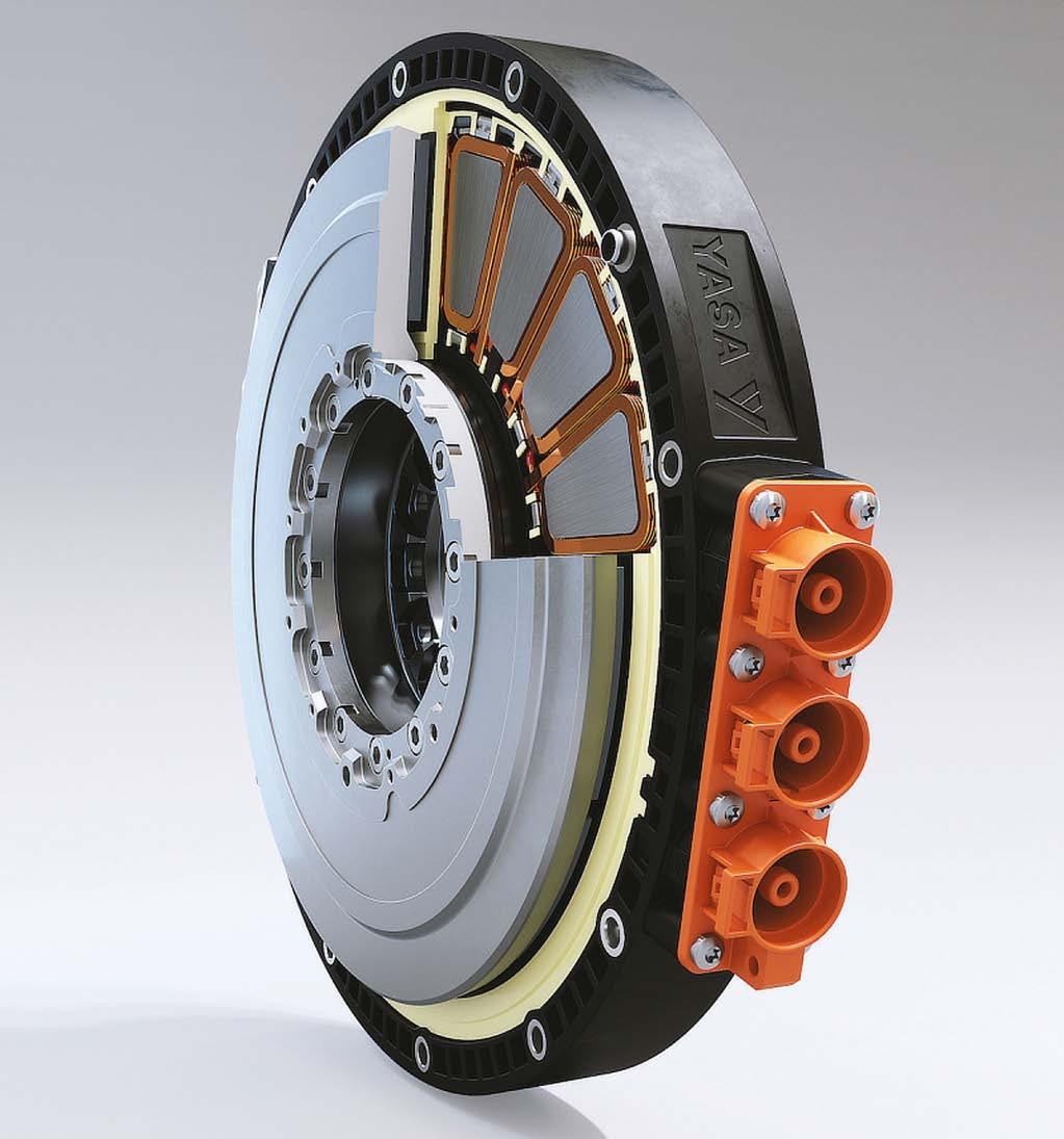
OCTOBER 2022 www.racecar-engineering.com 57 FOR MORE PRODUCT INFO WWW.KRONTEC.DE AIR JACK SYSTEM HYDRAULIC SYSTEM STEERING WHEEL QUICK RELEASEQUICK DISCONNECT COUPLING FIRST CHOICE OF TOP-LEVEL MOTORSPORT TEAMS AND RACE SERIES KRONTEC MASCHINENBAU GMBH OBERTRAUBLING, DEUTSCHLAND +49 (0)9401 – 52530 KRONTEC DESIGN LIMITED SWINDON, ENGLAND +44 (0) 1793 – 422000 MECHANISMNEWRFC-89-K-LMLOCKING SYSTEMFLOWRFC-FM20METER NEW PRODUCT 2021
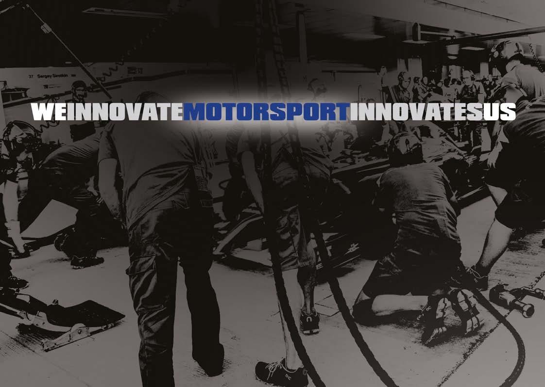
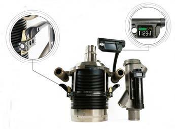


By STEWART MITCHELL You can’t really avoid additive manufacturing (AM) in motorsport these days. It’s everywhere, and for good reason. AM is a process of joining materials to make objects from 3D model data, usually layer upon layer, as opposed to traditional ‘subtractive’ manufacturing methodologies. It is wellunderstood that AM gives engineers far more freedom to produce components with complex shapes. It also has the potential to deliver a more significant impact on technology and manufacturing for industry than almost any other technology to date.
The ‘sweet spot’ for AM lies in where designers want to create a component with only the required structures for its application, and optimise its size and weight. For example, designing hollow tubes and I-beams inside a component can help create a stiff internal structure with minimal weight. How parts are loaded determines where material needs to be present, and often the centreline of a structure doesn’t require any material, as the outside of the part carries the stress. ‘The key element is the part’s application, as this will dictate the technology, material, and any post processing requirements to ensure it is fit for purpose,’ says Samuel Persaud, head of projects at Graphite Additive Manufacturing. ‘Design for manufacture considerations is more relaxed for AM, allowing far greater ability to design without many of the constraints traditional manufacturing has,’ Fuller adds, ‘Limitations of imagination and creativity are common and, as with any industrialised manufacturing technology,
‘The tolerance and accuracy will very much be technology and material specific. Ultrahigh resolution printers can build down to 25 microns’
charmingPrints
Motorsport is a constant exercise in continuously improving performance within rapid time-frames, so it’s not surprising to find that this advanced manufacturing technology is a crucial element in implementing new designs and technology. As Michael Fuller, CEO and founder of Conflux, which specialises in AM heat exchangers, says: ‘With AM, freedoms are simply realised in hitherto un-manufacturable geometries.’
58 www.racecar-engineering.com OCTOBER 2022
Additive manufacturing is transforming motorsport engineering, but how exactly does it work? Racecar spoke to experts involved in the 3D printing sector to get the inside line on this spellbinding technology
Kevin Lambourne, managing director, Graphite Additive Manufacturing AM is used at all levels of motorsport. This is the Loughborough University Formula Student team’s steering wheel
AMGraphite
AMGraphite TECHNOLOGY ADDITIVE MANUFACTURING
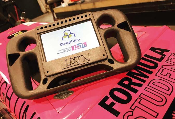

‘Surface roughness aside, the microstructure across bulk geometries (>0.5mm) can be consistent, and this is imminently achievable and measurable,’ says Fuller. ‘In the case of thin walls and microfluidic channels, surface roughness can be in the same order of magnitude as the geometric features themselves.’
But whatever the limitations, there are plenty of 3D printing solutions to choose from. Indeed, Nathan Rawlings, UK Manager AM is particularly suited to complex geometries. This water outlet is made from carbon fibre reinforced plastic Sinterworx C6 material
The surface finish with an additive manufactured part is usually much higher, or ‘rougher’, than precision subtractive techniques, so there are still plenty of components that must be manufactured using more traditional methods.
‘When used for additive manufacturing, it’s not uncommon to build a part, measure it and scale areas of the part file to dial in tighter tolerances against the printed part.’
But high accuracy is certainly not impossible with AM. Kevin Lambourne, managing director of Graphite Additive Manufacturing, says: ‘The tolerance and accuracy will very much be technology and material specific. Ultra-high-resolution printers can build down to 25 microns, but these machines are limited in materials and are only suitable for small components.’
OCTOBER 2022 www.racecar-engineering.com 59
foundational training in design for additive manufacturing is a critical success factor for the roll-out of the technology.’ With traditional manufacturing and surface finishing manufacturers can produce tolerances of as little as 0.2microns, and a surface finish of Ra 0.2. This level of refinement is not yet possible with AM without severe post-processing of the part after it is complete, and even then, it’s unlikely to be that precise. ‘3D printing struggles to meet the tighter tolerances yielded with other traditional manufacturing methods, typically falling within +/- .125mm x, y or z direction,’ says Michael Littrell, CEO of CIDEAS.
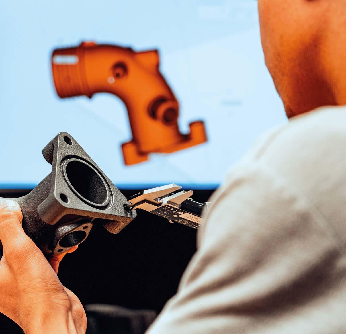
OCTOBER 2022 at EOS, surmises that there are now so many types of additive manufacturing that there is likely a solution for most applications.
‘Multi Jet fusion and SLS are becoming increasingly popular because of their potential for low to medium volume production applications’
Producing parts on-site at Conflux’s vertically integrated additive manufacturing facility. AM technology is ideal for making the complicated heat exchangers the company specialises in
ConfluxConflux
60 www.racecar-engineering.com
TECHNOLOGY ADDITIVE MANUFACTURING
Conflux Technology’s 3D-printed water charge air cooler has very fine features and highly elaborate shapes on the inside
Nathan Rawlings, UK Manager, EOS
Software Additive manufacturing software is constantly improving. However, as Lambourne points out: ‘For most projects, the extra time and cost involved with FEA is not being utilised, but we hope to see this changing as the industry progresses further towards production. Designers have other great tools to optimise their parts, including 3D mesh structures to lightweight parts.’
‘There are four key technologies which are the most used and established.
DLMS and FDM technologies are often used for the most demanding motorsport applications. However, Tim Chapman, head of additive manufacturing at McLaren Racing says: ‘Stereolithography technology and the materials have evolved – changing the way we use it. We do not just manufacture prototypes anymore; we now produce many full-scale components and full-size tooling. Wind tunnel testing is still the gold standard when assessing how every surface works together, either as an assembly or as a complete car. Our [Stratasys] Neo series of 3D printers have helped us to dramatically reduce the lead times of our aerodynamic wind tunnel components and projects.’
‘The market can appear quite confusing to someone with no previous experience, and it depends on what you are trying to achieve,’ he says. ‘Some technologies are ideal for wind tunnel testing, but you wouldn’t make a test or functional part with that technology.
SLA (stereolithography), curing a resin in a vat with UV light, SLS (selective laser sintering) sintering polymer powders into 3D shapes, DMLS (direct metal laser sintering) melting metal powders into a 3D shape using high power lasers and FDM (fusion deposition modelling) a printing method but in a structural way,’ Rawlings adds. ‘By units sold, FDM is the most popular technology worldwide due to its low cost and ease of use,’ Rawlings continues. ‘Due to speed, build volume and repeatability, multi Jet fusion (MJF) and SLS are becoming increasingly popular because of their potential for low to medium volume production applications.’
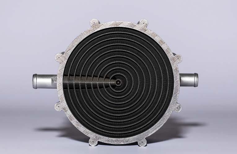
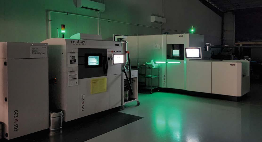
exchangers.motorsportperformanceUltra-highheat - Low weight & pressure drop - Lower cost - Rapidly configured - 3D printed products Get in front with Conflux conflux-technology ConfluxTechnol1 Conflux Technology www.confluxtechnology.comConfluxHeatExchangersdeliver industry leading performance. Our motorsport products are scalable and configurable to unique boundary conditions, performance and packaging requirements. Learn more at confluxtechnology.com CartridgeWater Charge Air Cooler Oil/Water Cooler The cutting edge in additive manufacturing


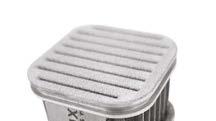

TECHNOLOGY ADDITIVE MANUFACTURING
Most parts produced using AM are designed in 3D CAD and run through a program that turns them into 2D sections that are then fed into the AM machine software as instructions for the build. ‘Conventional CAD/ FEM software is developing increasingly in the direction of AM design with new features,’ says Rawlings. ‘A typical example is thread modelling, and for a few years now, a thread can be modelled and manufactured using the thread feature with just a few clicks. Before that, the thread was only hinted at for a drawing, but there was no physical thread.’ The AM software automatically chooses the laser power and the speed at which it passes across the powder bed. ‘There are standard parameters for which these values are already specified,’ Rawlings says. ‘Often, however, these parameters do not get the maximum out of the parts. With appropriate knowledge and experience, you can adapt or optimise the parameters for a specific part to achieve the best possible part quality and reduce the printing time.’
It’s fair to say, though, that material science has been the key development path for AM. ‘For any given technology, advancements in its materials has proven more beneficial than incremental hardware changes,’ says Lambourne. ‘That’s the very reason we formulated our own high performance Sinterworx C6 [carbon] and G4 [graphite] filled SLS materials. It can seem
A significant challenge facing component designers who want to manufacture parts using AM is defining the properties of the layered construction. The problem is that much of the CAD and FEA software cannot define a layered material’s properties because CAD programs work out each structure as an idealisation. The structure as it comes out of the AM machine is not ideal – it has very rough surfaces and other imperfections, and the geometry at a microscopic level often diverges significantly from the idealisation.
resolution, DLP parts are finding their way into mass customised products such as low production vehicles components, connectors, fasteners and more.’
62 www.racecar-engineering.com OCTOBER 2022
But Fuller says there have been huge strides across all disciplines of the AM value chain when it comes to CAD and FEA software for defining the properties of AM construction. ‘Design automation and topological optimisation tools are now very well suited to AM. Multi-physics modelling and simulation of the process itself are utilised to predict manufacturing phenomena [akin to mould flow or weld analysis] and, critically, the advent of in-process monitoring supports a very high level of real-time QA.’
The McLaren Formula 1 team uses Stratasys stereolithography 3D printing technology to help reduce its part production lead times
AM operation
Detailing the popular polymer AM operations, Littrell says: ‘The general principle of Powder Bed Fusion is to print parts by solidifying the cross section of the CAD model into a fine layer of powder [usually a derivative of Nylon]. The un-solidified powder acts as a support structure enabling complex geometries to be built in one piece quickly, but most importantly, allows for stacking parts above one another in the vertical Z direction.
‘In this technology, parts can be built solid, or large cross sections can be built with a honeycomb interior to reduce material usage and improve throughput. This process is ideal for jigs, fixtures, production aids, and may also be used in some aerospace applications.
‘Digital Light Processing (DLP) technologies have gained a lot of interest due to their small footprint, high speeds and extremely high detailed parts,’ Littrell continues. ‘Although production sizes are limited, complex resins have been developed recently that are very close to traditional production grade plastics. Due to the material capabilities and fine feature
On the metal AM side of it, Samuel Persaud, head of projects at Graphite Additive Manufacturing says: ‘SLS and MJF offers the most design flexibility, though restrictions that we watch for carefully are minimum wall thickness and getting access to remove unwanted material from inside components.’
Stratasys
‘It’s very efficient, quick and can yield a high volume of plastic parts quickly,’ Littrell adds. ‘Fused Filament or FDM technologies feed a plastic filament from a spool into a computer-controlled head and then it deposits hair thin strands of melted plastic layer by layer. It is a very linear process and build speeds are somewhat slow, but extremely large durable parts in several exotic plastics can be achieved.
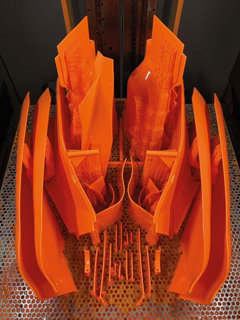
‘Chemists are now realising breakthrough combinations, inching them closer to traditionalUsually,thermoplastics.’themachine’scomputer will work out every layer’s power and speed to manufacture the part as desired. ‘In polymers, SLS machines have default settings and parameters that are embedded in the build profiles,’ Littrell says. ‘An AM operator can fine tune and adjust the scanning speeds and laser intensity manually, even down to the individual part in a machine with varying part geometries. But the calibration of the optics, powder mixture, thermal management of the bed temps and proper cool-down procedures are equally important.’
The trade-off is between the speed and resolution – the higher the speed of the machine, the lower the resolution. ‘Largely this is determined by the machines’ fixed resolution and the technology,’ says Persaud ‘SLA is resin based, offering a better surface finish over SLS or MJF, which requires bead blasting to remove surface powder. Vapour smoothing can be used to improve SLS and MJF as it removes layer lines and leaves a smooth, glossy surface finish.’
However, when it comes to the part’s surface vs the core volume, in some cases it might use different laser parameters to create different surface finishes or areas of the component. The resolution of each layer at the part’s boundary and its orientation determines the finish characteristics. If the surface takes the bulk of the load, it must be tailored differently from the interior section to create a different structure.
Persaud notes that, generally, FDM is the only AM technology where hollowing parts is common practice, nearly all of the other technologies will build parts solid if they are modelled as such. Increasing the laser’s power at the surface increases the resolution of the layers in that area. Suppose you understand the principles of how the layering works on a particular material and have the freedom in the software of the given machine to change the laser’s power and speed. In that case, using this technique, you can get down to feature sizes of between 100 and 200 microns.
Post processing After the AM part is complete, postprocessing must take place to ensure it is going to perform as desired. ‘One of the most important elements is that the post-processing is already kept in mind when designing components, i.e., how to ‘An AM operator can fine tune and adjust the scanning speeds and laser intensity manually’ Michael Littrell, CEO of CIDEAS McLaren’s array of in-house Stratasys 3D printers. The team says the technology allows it to produce wind tunnel parts and other components very quickly and to a high level of accuracy
OCTOBER 2022 www.racecar-engineering.com 63 that material innovation in the market is fairly slow, but looking at the bigger picture, AM materials have developed to a price and performance level where they are more widely accepted for production parts.’
‘The demand in adopting AM in recent years has increased the number of available performance materials,’ says Littrell. ‘Traceability is paramount and unique features such as: flame, smoke, toxicity ratings, ESD, chemical resistance, UV resistance, durability and other exotic characteristics are starting to show up. ‘The most notable area of growth in recent years is within photopolymers,’ Littrell adds.
Heat exchangers and other components requiring a high surface area and volume ratio can be made much more efficient if the machine is tailored to the specific project.
‘The challenging and exacting nature of heat exchanger geometries necessitate bespoke process parameter sets to be developed, including but not limited to laser power and speed,’ says Fuller. ‘Surface finish is a function of multiple variables including geometry orientation, process parameters, laser spot size, powder particle size distribution, gas flow, build plate geometry density, layer height, material type and quality and laser calibration.’
Stratasys

Major machine manufacturers have demonstrated automated factory solutions that promise to dramatically improve productivity across the complete AM process chain, from CAD/CAM file preparation to part build, heat treatment and build plate removal. These systems remove some of the manual processes inherent in the AM part production process and automate them into one system. Hyperganic’s rocket engine design study. The possible applications of AM is almost unlimited and it’s already used in many sectors
The metal AM build process. Direct metal laser sintering (DML) melts the powders into a 3D shape using very high powered lasers
‘I cannot overstate how important these benefits are in F1,’ Chapman adds. ‘With super tight deadlines to deliver cars to the next race and where the smallest design iteration can make all the difference between winning, losing or making up positions on the grid.’
Automated solutions
64 www.racecar-engineering.com OCTOBER 2022 TECHNOLOGY ADDITIVE MANUFACTURING de-powder the component or design the component so that I need little or no support structures,’ says Post-processingRawlings.itselfhas evolved a long way in the last five years. ‘In the past, it would often be obvious a part was produced using AM as you would be able to see the build lines,’ says Rawlings. ‘This is no longer the case as companies now specialise in providing automated post-processing, making it almost impossible to distinguish from more traditionally manufactured parts.’ Conflux utilises a Synchrotron light source to acquire a significant amount of highresolution CT scan data on parts. ‘These large CT data sets [>15TB] are analysed with our in-house software suite [Conflux Quantify] to measure 3D pore density distribution and morphology, surface roughness, wall thickness, feature distances and identify critical defects,’ says Fuller.
EOSEOS
Production systems Rawlings says that AM machine development has been a process of continuous improvement, where each new system gets quicker, produces better quality parts and features more integrated quality controls as their evolution continues.
‘One characteristic about AM is the number of new machine manufacturers and start-ups joining makes it look like the evolution is happening over months, but at the production end of the market development it is much slower, with the occasional jump,’ he says. Formula 1 teams tend to use additive equipment 24/7, and full-scale production for AM parts has emerged in the past few years. ‘We find the high-definition components from our [Stratasys] Neo machines require minimal hand finishing, which allows much faster throughput to the wind tunnel,’ says Chapman. ‘In addition to speed, we can now produce wind tunnel parts with supreme accuracy, detail and surface finish, enabling our team to enhance testing and find innovative new ideas to improve performance.
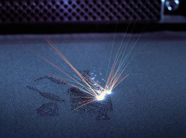
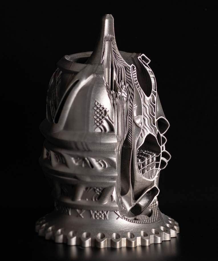


SLA (stereolithography) was used to produce this HUD Navigation smart motorcycle helmet demonstrator. Accura 25 resin was chosen for its accuracy, durability and heat deflection. The process, which cures a resin with UV light, gives a good surface finish
The heat treatment module in the system is considered critical, as when the build is complete the heat treatment must be carefully controlled to ensure the part quality is maintained. The AM process usually causes tension in a part, and if it is allowed to cool to room temperature before it is put through a heat treatment process, it can warp and be ruined. The heat treatment does not occur in the build area; the modular system uses robotics to move the part to the heat treatment module. After heat treatment, the product is transferred to a part removal module using robots. That removes the part from the build plate; which it is attached to to keep it fixed and in one orientation during the build process, and to remove heat from the part during production. Removing the part from the build plate must be completed with high precision to ensure it comes off the plate cleanly and is not damaged. The part removal area of the machine turns the built component upside down to ensure excess powder does not obstruct the part during the removal process, and it is cut off the plate using a robotically controlled band saw. The part is then lowered into a bin with a foam inlay, turned upright, and transferred into a machining area, where the final machining occurs. The user can automatically set the entire system to run each manufacturing and posttreatment process and then return to the machine later to retrieve a completed part, which is very convenient. The use of additive manufacturing in motorsport certainly shows no signs of abating and it is likely that a much higher percentage of components will soon be manufactured using this technology. We will undoubtedly also see the emergence of larger, faster and more precise machines, and many more materials.
TECHNOLOGY ADDITIVE MANUFACTURING
Heat treatment
CIDEASbyPartsBuildCIDEASbyPartsBuild
CIDEAS used FDM, SLA and CLIP processes to create this highly detailed 100 per cent 3D printed trade show display engine model
These AM production systems require the user to load the build plate, and then everything runs automatically until the part is complete. The systems are modular, so they can be built up to each machine user’s requirements to complete a part from a CAD/CAM file upload to a serviceable component. They also often feature a control module for the filter system, cooling system, powder delivery pumps, lasers and other peripherals, multiple build modules, a heat treatment module, a post-processing module and an inspection module.
66 www.racecar-engineering.com
OCTOBER 2022
Two build chambers can even be built so that they will allow two parts to be manufactured simultaneously. Because the powder handling is integrated into each module, the system allows the operator to use different materials in each build area.
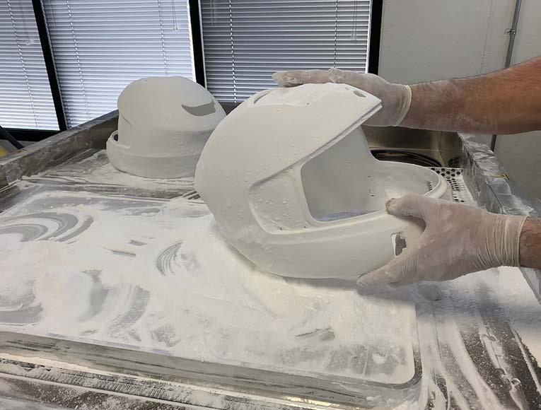
OCTOBER 2022 www.racecar-engineering.com 67 CMYCYMYCMYMCK RacecarEngAd-BurnsStainless-2204.pdf 1 4/5/22 2:14 PM CMYCYMYCMYMCK RacecarEngAd-BurnsStainless-2204.pdf 1 4/5/22 2:14 PM mezzo TECHNOLOGIES Mezzo Technologies first introduced microtube heat exchangers in the Indy 500 in 2008. Since then, Mezzo has been THE innovative supplier of microtube radiators, intercoolers, and oil coolers across the spectrum of high-performance automotive racing (Formula 1, LMP-1, Daytona Prototype, Indycar, etc.). If you want to explore the advantages of microtube products, don’t look at pretenders – call Mezzo! 10246 Mammoth Ave., Baton Rouge, LA 70814 USA Tel: +1 (225) 442-6965 • www.mezzotech.com • kelly@mezzotech.com
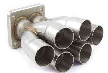

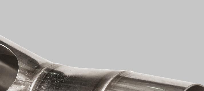
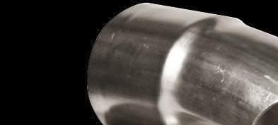


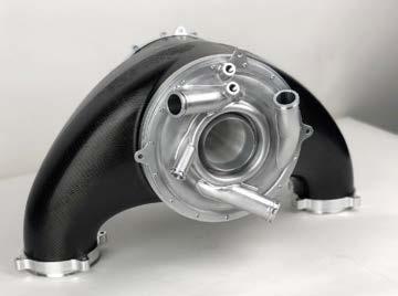

Parameter Time Time under full throttle 82.6s Time under part throttle (50%) 13.46s Time under full braking 28.5s We now need to put some specific electric numbers in to the mix. The electric motor we will use for this study is the Remy HVH 250 motor. We will also base our cells around
68 www.racecar-engineering.com OCTOBER 2022 Guilty as charged Why competing with an electric-powered GT car might not be such a great idea
The case study shows just how marginal battery powered EV is, and it raises some serious questions about dispensing with the internal combustion engine well before its time is truly up. This is put into even sharper relief given what KERS brings to the table.
TECHNOLOGY SIMULATION
To frame this study let’s first discuss the vehicle parameters for a contender in the Bathurst 12 hours. Note the keyword here; contender. One of the problems with motorsport is, due to the challenges we are facing, the regulatory bodies are grasping at anything to keep it relevant. However, this takes away from motorsport the key goal, which is to go as fast as possible. Everything should flow from this in racing, and we are losing it at our peril. So, with this as our perspective, let’s examine where electrics and KERS come into the picture. To this end we will be using the Lamborghini LP 560 GT3 as our baseline vehicle. This is a racecar I have been closely involved with, because back in 2012 I was the data/performance engineer for the Consolidated Chemical LP 560 entry in the Bathurst 12 hours. Table 1 below shows some specifics for this racecar.
By NOWLAN
Table 1: Car specifics LP 560 GT3
DANNY
XPB
This study examines the possibility of competing with an all-electric GT car at the Bathurst 12 hours. The base model is a Lamborghini LP 560, a racecar the writer is very familiar with Given the peak power of the motor is 305kW, we will need to run an AWD configuration Nearly three years ago I did a study comparing an all-electric GT3 contender vs a KERS GT3 car for the Bathurst 12 hour race. In light of what is on the legislative table for Europe right now, in terms of banning the sale of new internal combustion engines post 2030, and what has already been passed in some Australian states, some sanity desperately needs to be injected into this discussion.
Parameter Value Mass 1300kg Peak power 380kW Time for a stint 45min To kick off this discussion let’s consider what an all-electric option would look like. To this end we need to review a typical lap, and this is presented in Figure 1 As discussed in one of my earlier articles on electric propulsion, what we need to determine next is the time on brakes and time under full throttle. The data for this, from the lap in Figure 1, is shown in Table 2
Table 2: Specifics from Bathurst lap for Electric analysis

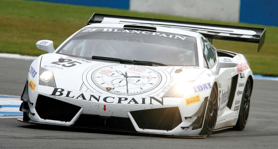
OCTOBER 2022 www.racecar-engineering.com 69 Thunder Power Rampage 7700mAh 65C cells. The relevant parameters for all this are presented in Table 3 Table 3: Electric powertrain parameters Parameter Time Remy HVH 250 peak power 305kW Motor operating voltage 650V Cell weight 0.2kg Regen power 150kW Cell operating voltage 3.5V Given the peak power of the motor is 305kW, we’ll need to run an AWD configuration. This will bring us to our peak power configuration of 380kW (the power of the original LP 560 GT3). Let’s now crunch the numbers. Firstly, let’s establish the currents under power and regen. For acceleration we have Equation 1 and for regen we have Equation 2 Now that we have established the acceleration and regen parameters, we now need to calculate the Ah used over the lap. Crunching the numbers we have Equation 3 We now need to calculate what we need from the battery pack, and this is the critical point of this discussion. Given that Figure 1: A typical lap of Bathurst What we need to determine is the time on the brakes and the time under full throttle (3)(2)(1)


Non-KERS
For the sake of brevity we selected discharging down the start finish straight at Bathurst. The results were a dead heat with a lap time of 2:04.95s. However, the overlays of the data show a very different story, as illustrated in Figure 2
As an interesting aside, the Tesla Model S 85kWh battery pack weighs in at 540kg and has 7104 cells. So, we need to ask: is this an option? To answer, we need to crunch some basic numbers. The Model S has engine options that range from 285kW right through to 568kW. Given the HVH 250 has a base power of 305kW, it’s a pretty fair estimate that this motor and the Tesla motor would be running similar voltages. So, calculating the Ah we have Equation 5. That is about half the capacity of what we need. That, coupled with the practicalities of getting a 540kg battery in and out of a car every 30 minutes, means an all-electric contender for the Bathurst 12-hour race is simply not practical. Also, no amount of well-meaning environmental spin is going to change this hard fact.
The non-KERS baseline is coloured and the black is the KERS lap. Due to the fact the start finish straight is short at Bathurst this has skewed the C-Time plot. However, the impact is completely obvious. Not surprisingly we do pay in corner speed and end-straight speed for the KERS system. This averaged about 0.2-0.3km/h per corner and we where down 1 to 2km/h going down Conrod straight. However, with the KERS engaged with a 300kW discharge the results down the start finish straight are incredibly stark. Going into Turn 1 without KERS the
Parameter Time Discharge limit 300kW Regen power limit 150kW Charge limit 2MJ KERS weight 60kg Regen Power 150kW Cell operating voltage 3.5V
TECHNOLOGY SIMULATION
Figure KERS vs at Bathurst
(6)(5)(4)
70 www.racecar-engineering.com
Table 4: KERS parameters
OCTOBER 2022 we’ll be running 20 laps over a 45-minute stint we’ll need at least 253Ah of capacity. So the number of cells we’ll need is shown in Equation 4. Now you don’t need to be a rocket scientist to figure out a pack mass of 1264.8kg is simply not practical.
However, while the all-electric option for a GT3 contender isn’t practical, we now have the mathematical basis to nail down what a KERS electric option would look like. From our earlier analysis we can charge about 1.82Ah per lap. So revisiting Equation 4 and using a 3300mAh Thunder Power pack (the cells weigh in at 80g) we have Equation 6 This means to store the energy charge for a lap we would need a battery pack that weighs about 15kg. By the time you install cooling and battery protection this might jump to 20kg. Also, the Remy HVH motor weighs in at 43kg. So tacking on a KERS system to a rear-wheel drive car would incur a weight penalty of 63kg. It is now time to put some serious numbers into this, so let’s investigate using the ChassisSim KERS feature. For the purpose of this investigation we are using the parameters in Table 4 for the KERS feature.
2:


OCTOBER 2022 www.racecar-engineering.com 71 motorsport@fclane.com +44 (0) 1403 790 LANEMOTORSPORT.COM661VISITOURWEBSITEFOR NEWON-LINEANDAPPLICATIONSTECHNICALSUPPORTGUIDECATALOGUESDATASHEETS3DCADMODELSSHOPANDPRODUCTSINFO MOTORSPORT CONNECTORS AND ACCESSORIES IMMEDIATE DESPATCH OR RAPID ASSEMBLY WE CONNECT TECHNOLOGY No MOQ or MOV :��ARTEIC MDTDR§PDRT ELECTRONIC§ l=M�@#•1;iiW=IOit•W•Wniil-t A switch panel and Power Distribution Module in one. Dur Power Distribution Panels are a fully integrated solution designedto replace all the fuses. switches and relays of your race car. • CONFIGURE CHANNELS IN SA STEPS UP TO 30A. • CHANNELS CAN BE PROGRAMME□ TO CONTROL HEADLIGHTS/WIPERS/RAO FANS/STARTER MOTORS etc. • EACH OUTPUT IS PROTECTED FROM SHORT CIRCUITS ANO OVER-CURRENT. • AOOITIONAL INPUTS ALLOW CHANNELS TO BE CONTROLLED BY ECU OR SWITCHES ON STEERING WHEEL • COMES WITH LABEL SHEETS FOR FULL CUSTOMISATION RETRO EDITION NOW AVAILABLE. • ND COMPLEX CDNFIGURATIDN SOFTWARE -AMP SETTINGS AND LOGIC FUNCTIONS ARE SELECTED THROUGH THE FRONT PANEL BATTERY l!!iOLATOR XR Deaigned fur ECU's/PDM'sn,atarapart BATTERY l!!iOLATOR liT Oeaigned fur OEM ECU"s/lgnition systems GD TD DUR WEBSITE TD VIEW DUR FULL RANGE OF MDTDRSPDRT ELECTRONICS www.CARTEKMDTDR5PDRT.com B and f 6 channel versions available 4-i•tli•liMf:l=!ii@&Zi•ifflM;f#' Cartek Battery Isolators are designed to overcome all of the problems and restrictions associated with mechanical and electro/mechanical battery disconnects. • FULLY ELECTRONIC WITH ND MOVING PARTS CDMPLETELY RESISTANT TO SHOCK ANO VIBRATION. • MUCH SMALLER ANO LIGHTER THAN TRADITIONAL KILL SWITCH. • MEETS NATIONAL AND FIA REGULATIONS. • STATUS LED FOR FAULT DIAGNOSIS. • SEALED INTERNAL ANO EXTERNAL SWITCHES REPLACE TRADITIONAL PULL CABLES THAT ARE PRONE TO SEIZING. • MOUNTS CLOSE TO THE BATTERY FOR REDUCE□ CABLING. • QUICK AND EASY TD INSTALL.


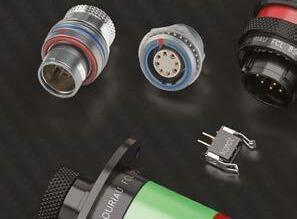
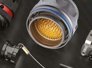


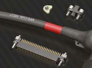
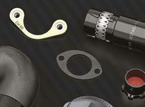


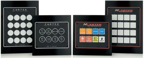

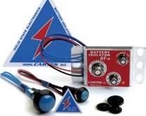
TECHNOLOGY SIMULATION Figure 3: Available
On top of this, with the battery pack that can store 4.28MJ of energy you have plenty of options. Just imagine the effect this can have when you have complete liberty as to where you can use it. Since I wrote the last article on this subject a lot of ChassisSim development in the Hybrid/electric vehicle space has been going on, in optimising the deployment of regen to maximise vehicle performance. Now while I’m not at liberty to chat about the specifics here, suffice to say there is considerable room for tuning.
The other thing to keep in mind in this analysis is we haven’t optimised it yet. I’ve literally tacked this on to the existing car. I haven’t even played with the brake bias, let alone optimising where on the circuit we have used this. Just imagine it unleashed climbing up the mountain, or going down the mountain on the Conrod straight. Also, if the KERS system is designed into the car from day one, I would wager the weight penalty could be appropriately minimised.
72 www.racecar-engineering.com
The other spin off from this comes from looking at the front tyre forces, as shown in Figure 3. In this graph the key traces to observe are the bottom two, where we see max longitudinal tyre force plotted against lateral force. I’d like to bring your attention to where the cursor lies here. There is a differential force of 100kgf on the inside front and 200kgf on the outside front. Strictly speaking, to calculate the available force I should do a traction circle calculation. I’m actually going to go off the minimum forces because I am deliberately being conservative. So, to estimate the engine power we could apply we have Equation 7 To put this in perspective, this represents 15.6 per cent of the base 380kW. Most engine builders would sell their souls to the devil to get this kind of improvement. Also, we are applying this at just one end. Can you just imagine the implications of this being incorporated into an all-wheel drive platform, such as the Nissan R35 GTR? One other thing I would like to add to the discussion here is the state of play regarding battery energy density. Currently, battery energy density is hovering around the 170 to 180Wh/kg mark. Some battery EV and green advocates would say this number is soon to be eclipsed. Now, anyone familiar with my writings on electric vehicles will also know of my background in high performance radio-controlled electric powered aircraft. Those of us who fly these watch the available energy densities like hawks, and for the last five or so years this has actually stagnated. Consequently, betting the farm on battery EV, which is either going to be difficult to achieve or near impossible, is a very dangerous gamble indeed. But as this study shows very clearly, there are a lot of benefits to the hybrid approach, and this is something that the OEMs and legislators should be made aware of. In closing, while the all-electric option was not feasible, the KERS electric option is not just viable, but in a technically open formula you would be mad not to consider it. The deltas on the start finish straight speed of over 40km/h meant this is an option to consider very seriously. Also, the loss in corner speed was by no means an onerous one. It also has the potential to produce exciting racing because in a wheel-to-wheel battle you will never fully anticipate where the KERS will be discharged. So, as we debate which way we tackle going to a carbon neutral infrastructure, this study clearly shows the days of the internal combustion engine are far from over and we would be mad to sacrifice it on the altar of ill-advised green policy. It also shows us how much benefit can be gained from marrying current and proven battery EV and ICE technologies, and we would be foolish to ignore the possibilities this presents. front tyre forces
Going into Turn 1 without KERS the end speed is 211km/h, with the KERS this jumps to 251.4km/h (7)
OCTOBER 2022 end speed is 211km/h, with the KERS on this jumps to 251.4km/h. That’s a push-to-pass you simply cannot defend against.
in Turn 1
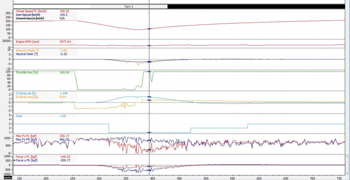
12-13 JANUARY 2023 TRADE | 14-15 JANUARY 2023 PUBLIC AUTOSPORT INTERNATIONAL | 2023 Kick start your motorsport season here! AutosportInternational.com 12-15 JANUARY 2023 | NEC BIRMINGHAM Kick start your motorsport season AutosportInternational.com EUROPE’S EVENTMOTORSPORTLARGESTISBACK INTERNATIONAL PERFORMANCEINTERNATIONAL&TUNINGCARSHOW 12-15 JANUARY 2023 TRADE & PUBLIC 12-13 JANUARY 2023 TRADE ONLY 12-15 JANUARY 2023 TRADE & PUBLIC SAVE THE DATE ASI Advert Le Mans.indd 2 19/04/2022 11:25 am


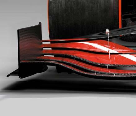
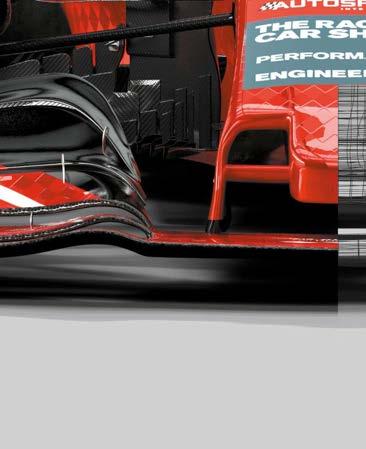


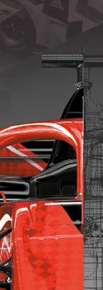


74 www.racecar-engineering.com OCTOBER 2022
For all the technology that exists in modern racecars, driving them is still a fundamentally analogue experience. Drivers rely on intuition, sensing minute changes in the forces acting on the vehicle and those fed back through the controls, not to mention other cues such as watching for braking markers or listening to the engine revs.
‘If you keep pushing the boundaries in simulation, sooner or later you will come across Ansible Motion, because they are one of the leaders when it comes to high-end simulators,’ says Gorka Arce Alonso, who is senior simulation engineer for racing at AVL Racing. ‘We promote the use of Ansible Motion’s simulators to our customers, and we also use Ansible’s facility in the UK for some of our own projects.’
Driver in the Loop (DIL) simulators are designed to provide a bridge between the analogue world of the race driver and the increasingly digital realm of modern computer-based engineering. In an era where top-flight race teams frequently test their new car in the virtual world before its tyres meet the tarmac, simulation has become a hugely important tool.
Teaming up AVL Racetech is the motorsport arm of Austrian engineering giant AVL List. It has been working on testing and simulation across all levels of motorsport for more than 20 years. Recently, the company has struck up a partnership with UK-based simulator manufacturer Ansible Motion and now the two organisations frequently work together on customer projects.
The best drivers in the world are extremely consistent from one lap to the next, but they achieve these results by responding to the track conditions and the racecar’s behaviour as it subtly changes. This human touch is the key to extracting performance from the car in the real world. For instance, a simulated engineering set-up that’s theoretically quicker around a track could, in practice, be a hindrance if it renders the racecar too twitchy for the driver to control.
The role of simulators within motorsport has evolved in the last few years. While simulators are still used extensively for driver training and circuit familiarisation, such as preparing Formula 1 drivers for the new Miami circuit that debuted earlier this season, for example, they are increasingly also being used as part of the R&D process.
Getting real
TECHNOLOGY DRIVING SIMULATORS
Ansible Motion’s Delta S3 DIL simulator in action. While hi-tech kit such as this has long been used for driver training it can now also play a part in the overall development of the racecar
How AVL Racetech is collaborating with wellknown driver toextraMotionmanufacturersimulatorAnsibletobringanlevelofrealityvirtualtesting
Gorka Arce Alonso, senior simulation engineer for racing at AVL, is a big fan of Ansible’s DIL technology

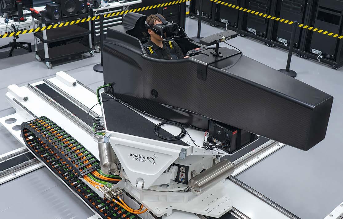
Today, young drivers grow up in a world where esports coexist with karting and the lower formulae. But a sense of physical connection is one that you can only really mimic with a top-flight pro simulator. As such, they’re becoming an increasingly valuable tool for engineers and drivers alike.
The two main benefits of testing in a simulator are time and money. In some series, track testing is heavily limited by the regulations. In others, there’s simply the practical consideration of finding a suitable venue and transporting the car to get there.
‘You can take much greater risks when you’re testing in the simulator,’ Alonso says. ‘If you build a physical prototype of a new aero kit or a new engine, you have to invest a lot more into creating that. You can’t afford to arrive at the track and discover that it doesn’t work. With a simulator, it’s like having three extra practice sessions each weekend.’
Alonso gives the example of using AVL’s simulation package, VSM, to evaluate a new aero map. This software features virtual drivers that provide a quick and convenient means of carrying out offline simulation, but human drivers are still needed to capture the most authentic results.
While simulators are still used extensively for driver training and circuit familiarisation, they are increasingly also being used as part of the R&D process
Of course, high-end simulators are a significant investment. But they are becoming accessible to a greater cross-section of the motorsport community. AVL Racing’s young driver programme, for instance, worked with the likes of Tatiana Calderon and Ferdinand Habsburg, giving them access to a top-flight simulator in the early stages of their careers.
OCTOBER 2022 www.racecar-engineering.com 75
Time and money
Hardwired The link between virtual testing and the physical world extends far beyond the cockpit. Recent years have seen a growing trend towards the use of Hardware in the Loop (HiL) test rigs in conjunction with driving simulators. This can vary from plugging in a single ECU to running a complete car on the chassis dyno. ‘At AVL, we can link a complete car on the test bench to a driving simulator,’ Alonso says. ‘It’s great for checking failure modes, because you are placing loads into the real engine, the real gearbox and the real drivetrain. So, for example, you can look at what happens if you’re part way through an endurance race and a sensor fails. And you can push the limits, because the dyno is such a controlled environment – you have so many sensors and so many alarms that you can predict a failure even before it occurs. That means you minimise the risk of actually damaging the car when you do trigger one of these failure conditions.’
As the driver concentrates on the racing line and braking points the engineer monitors the technical facets of the virtual racecar
By testing the racecar on a dyno linked to a simulator you can push the limits in a controlled environment
‘What we do is put the VSM model into the simulator,’ he says. ‘This is the first opportunity for a real driver to experience the car, the set-up and the track, and it can have a huge influence on the development of the car.’
And there’s always the possibility that you’ll arrive and find it’s raining (or even snowing, as the Formula 1 teams had to contend with in Barcelona a few years ago). But it’s not just a question of logistics.
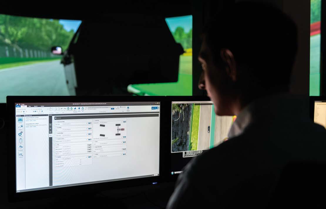
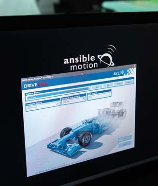
Next year the regulations will see the floor edges raised by 15mm, the diffuser throat will be raised, while care has been taken to avoid any impact on the teams’ designs of the mechanical components. The edge of the diffuser will also be stiffer, while an additional sensor will be mandated to monitor the problem more effectively.
New cost caps will be introduced from 2022-2025, set at 95m US$ rising to 130m US$ from 2026 onwards, after the initial development of the power units has taken place. It is a major change to the power unit regulations, one that will now be pored over by engineers at Porsche before an announcement will be made on whether or not to confirm its participation.
It’s hoped F1’s porpoising issue will be solved with changes to the plank and skids this season, and to the floor from next year; including lifting the outer edges by 15mm and raising the diffuser throat
Formula 1 paves way for Porsche
There are controls for dyno usage, including specifically identifying the number of test benches for single cylinder testing, power unit dynos, powertrain dynos, full car dynos and ERS tests. The amount of time that they can be used is also to be limited.
The FIA World Motorsport Council approved the new power unit technical regulations mid-August, during the normal shut down period, which has paved the way for Porsche to enter the series in 2026.
But according to a government document released in Morocco, Porsche will take a 50 per cent stake in Red Bull, while it has also trade-marked ‘F1nally’, indicating that it expects there to be a positive response to the regulations from the board.
Discussions in Technical Advisory Committee meetings found that the porpoising phenomenon appears to particularly affect cars that run with a low ride height and small amount of rake angle. The FIA believes that the problem will become worse in the future, and so has taken steps to address it. For this season, changes will re-define the stiffness requirements of the plank and skids around the thickness measurement holes.
The controversial move to try to tackle the issue by regulation has been taken against opposition from teams that have not suffered the same effects, leading to another debate over who is responsible for driver safety; the FIA which created the rules, or the competitors that designed cars that suffer the problem.
XPB XPB
New regulations tackle porpoising
76 www.racecar-engineering.com
OCTOBER 2022
The new regulations confirm that the fuel will need to come from sustainable sources as part of the series’ plans to go carbon neutral by 2030. The internal combustion engine will continue to be highrevving and will produce around 400kW of power. The MGU-H will be ditched while the battery cells will need to be non-exclusive in a bid to retain control over costs.
BUSINESS NEWS
Formula 1 has taken steps to address the porpoising issue that has affected some of the 2022 cars and which has left teams and drivers concerned for driver health.
The regulations mean that the existing partners in Formula 1, namely Mercedes, Ferrari, Alpine and Red Bull, have had to give up a significant part of their engine development over the last eight years; from when the hybrid era started in competition in 2014. However, with Honda having Limits on exhausts throughout the season, in line with power unit usage, is just one of many changes to the engine regulations from 2026 onwards
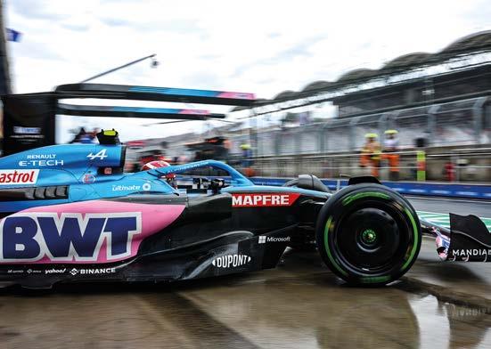
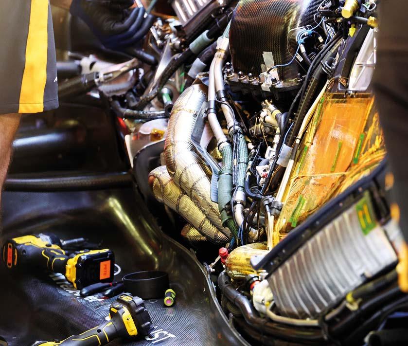
The power of the ERS will be increased to 350kW and the system will remain a key area of development for the PU manufacturers. The regulations aim to increase the road-relevance of the cells, power electronics and the MGU-K.
As previously mentioned, cells will be an area of development, but their supply will have nonexclusivity provisions to contain a potential cost escalation.
Former Williams F1 test driver and DTM racer Susie Wolff is to step down as CEO of the Venturi Formula E squad. Wolff joined the team in 2018 and went on to become its CEO in 2021. Next year Venturi goes into a partnership with Maserati, the legendary Italian marque supplying the team with powertrains for the 2021/2022 season.
ERS
The 2026 regulations have focused on four main pillars: the 2026 power unit will have similar performance to the current designs; an increase in the deployment of electrical power up to 50 per cent, and it will utilise 100 per cent sustainable fuel. There will be a reduction in the overall costs for competitors, while at the same time retaining the cutting edge technological showcase of F1, and making the rules more attractive to new manufacturers, making it possible for them to join the sport at a competitive level. Details of the new regs have been issued in a press release, and Racecar Engineering will examine their impact in our next edition.
The FIA World Motorsport Council is to revise its roll hoop testing criteria following the analysis of Zhou Guanyu’s crash at the British GP (above). Under new regulations to be introduced in 2023, there will be a change to require a rounded roll hoop to reduce the possibility of it digging into the ground upon car inversion. There will be a minimum height for the point of application of the homologation test, a new test for load pushing forwards on the hoop and a definition of new tests to be carried out by calculation. Further changes will come in 2024.
The FIA is rumoured to be considering dropping the LMP2 class from the FIA World Endurance Championship, despite previously committing to it. The new LMP2 cars will share their spine with the LMDh cars, and are therefore expected to be more expensive to buy and maintain than the current cars. With plans to expand the calendar to between 8 to 10 races, and air freight of the cars putting a limit of 34 on a single aircraft, it is not likely that the class will continue in the WEC. Teams will instead be able to run the LMP2 cars in the European and Asian Le Mans Series as the top class. Ferrari has denied that it has had problems in testing with its LMH car following online images of it on the back of a flat-bed truck during a test at Imola. The team says that it was carrying out fuel capacity testing, and that there was no major technical issue with the car.
There will be a limitation on ranges for the dimensions of the piston, crank, block, valves, injector position and turbocharger wheels. Fewer rare materials will be able to be used in the construction of the engine; there will be an extension to the number of standardised parts including the injectors, knock sensors, ignition coils, and other sensors, while systems such as the exhaust and ancillaries must be designed for a complete PU life.
OCTOBER 2022 www.racecar-engineering.com 77 confirmed its withdrawal from Formula 1 (hence the Red Bull link), and with the desire to have the Volkswagen Group as part of Formula 1, these existing manufacturers seem willing to drop some of their technology.
ICE
Fuel The new regulations stipulate that all fuel constituents must be fully sustainable and must come from either non-food-bio-derived; from genuine municipal waste; or from sustainable carbon capture. The greenhouse gas saving will be in line and stay in line with the latest European standards as they evolve. The fuel flow rate to the ICE will be limited by energy, as it currently is in the Le Mans Hypercar regulations and has been since 2014. No longer will the capacity be limited by mass or volume. More parameters will be limited to ensure the fuel developed is a relevant, drop-in gasoline that will be competitive whichever production method is used.
Design constraints have been introduced to improve ERS safety and the ability to police has been mandated. Controls have been introduced that either limit or require recycling of materials.
The ICE will remain with the 1.6 litre V6 architecture that the current Formula 1 cars enjoy, but there are big changes to the design criteria. The lower part of the engine, including the block, camshaft, conrods, pumps and ancillaries will be more prescribed. The upper part, mainly focused on the combustion area and the associated components, will also feature prescription but there will be more freedom to develop the combustion system for the new fuel. The objective is for ICE competition to focus primarily on the upper part, with the lower part being more controlled and having longer homologation periods. A key change to the ICE is that the MGU-H will be removed. It is a costly addition to the system that, while promising much in terms of road car application, is only really
For the first year of competition under the new regulations, drivers will each have four ICE/ turbo/exhaust units at their disposal, and three ERS. For 2027 these will be reduced to two.
SAFETY
IN BRIEF XPB
effective at full throttle. Variable trumpets and their actuation and control systems will also be removed.
‘The introduction of advanced PU technology, along with synthetic sustainable fuels, aligns with our objective of delivering benefits for road car users and meeting our objective of net zero carbon by 2030,’ said the FIA president Mohammed ben Sulayem. ‘Formula 1 is currently enjoying immense growth and we are confident that these regulations will build on the excitement our 2022 changes have produced.’
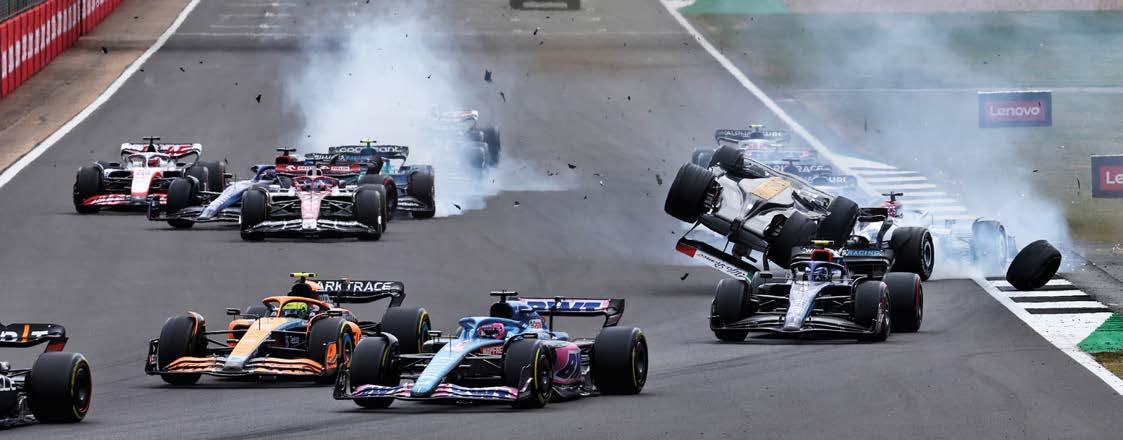
78 www.racecar-engineering.com OCTOBER 2022 BUSINESS NEWS
The team withdrew its cars from the race at Vallelunga, Rome, after a high-speed off for Yvan Muller and it pulled no punches, stating that ‘only a handful of cars in the remaining 11-car field finished without a tyre failure.’
& Co cars 30kg lighter than they were at the end of the 2021 season.’
JAS Motorsport has been KCMG’s technical partner in building and maintaining the cars since 2020. Hitech GP will run the operational side of the event and will set up the cars to be identical to ensure a level playing field. The KM MG-01 will have the same specification, configuration and set-up as the cars that raced in the Games three years ago.
‘This programme is a really special one to me,’ said KCMG founder Paul Ip. ‘I first discussed the possibility of KCMG manufacturing the F4 car for the FIA Motorsport Games with Charlie Whiting in Macau back in 2018. It was an honour to see the cars race at Vallelunga in 2019, and we’ve been waiting a long time for another edition.’
KCMG gets F4 Games nod
A Lynk & Co racecar leads the WTCR pack. The team has now, somewhat controversially, withdrawn from the rest of the series dues to tyre issues
The series also included two free test sessions in the weekend schedule to help teams to evaluate the effectiveness of the measures compared to the track characteristics.
‘From what we know and what we assess with the tyre manufacturer, the weakness is related to the tyre temperatures that were identified as being quite high or very high in specific track conditions,’ said the FIA’s director of sport and touring cars, Marek Narawecki. ‘Following this, there was a correction made in the manufacturing of tyres after the Nurburgring, which appeared to be sufficient for the next few races, but not the race in Vallelunga. What has been done is to clearly identify the situation when the tyre failures happen, to assess the conditions that have been applied to avoid this type of situation, so the weight reduction is to apply, the recommended settings for the tyres and the suspension, like the cambers, and to make sure that the teams will use new tyres in these tracks, so tyres that have not been submitted to the high temperature running conditions that could occur in the previous race. This is why we had the new tyres allocated for this race.
The KC Motorsports Group has been selected as the sole supplier of Formula 4 cars to the second FIA Motorsport Games, to be held in France in October. The Games, based on the concept of the Olympics, where competitors compete under their national flag in a variety of disciplines, has had a two-year Covid-induced hiatus after its inaugural event in Rome in 2019.
Cars line up at Vallelunga for the Formula 4 element of the inaugural FIA Motorsport Games in 2019
Lynk & Co pull out of WTCR
The team pointed towards its balance of performance criteria, saying that it ran 80kg heavier than the weightpointingracingtyresaninthesupplier,FIA,elaborated,‘EspeciallysaidthistheWTCRforcedHyundai,championship-leadingasonereasonwhyitwastotakethedecision,butpromoterWSChitback.‘WSChasalwaysrespectedcompetitors’decisions,butincaseIcan’tfindanyrationale,’itspresident,MarcelloLotti.aftertheWSChastogetherwiththetheseriespromoterandtyremeasuresthatwouldsolveissues,suchasa20kgreductiontheracingweightofallcarsandincreaseinthenumberofnewthatcanbeusedduringtheweekend.Andit’sworthoutthattheaforesaidbreakwouldmaketheLynk
‘[Because of the] conditions, and with the very deep track severity assessment for this track, Goodyear could reasonably state that there is a reduced risk of having this type of occurrence happening [elsewhere]. That doesn’t mean that the investigation stops now. There are some action plans and measures that Goodyear have taken for the next races to restore confidence in the tyre reliability independently of the track conditions and tyre situation.’ Rivals looked uncharitably at the Lynk & Co decision. ‘Concerning the problems with the tyres, we also experienced some in Vallelunga,’ said Comtoyou Racing team principal Jean-Michel Baert to touringcartimes.com.website‘Basically, when you mistreat the tyre there will be trouble. We identified the origin of the problem with our engineers, and in Race 2 we didn’t suffer from a single puncture again, which means that a solution exists, confirming that there is no real problem.’
The Lynk & Co Cyan Racing team has withdrawn from the remainder of the World Touring Car Cup, citing failures of the Goodyear tyre as its reason for doing so. In a statement, the team said that tyre failures have ‘become a recurring occurrence in the 2022 WTCR season’. As a result, the WTCR race of Germany in May was cancelled on the grounds of safety.’
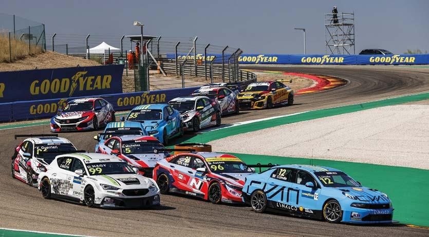
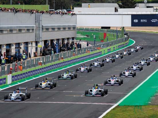
OCTOBER 2022 www.racecar-engineering.com 79 For further information: Web: www.rene-eder.com • Email: info@rene-eder.com Past projects include: GT cars (GT1/GT2/GT3), Prototypes (LMP2/3/ Renault RS01), Formula cars (Formula Renault/F2/F3), Spec series cars (Porsche Carrera Cup/Porsche Supercup), O Road cars Our Services include: • On and O track Research and Development • Race Engineering • EngineeringData/Performance/Simulation • EngineeringSuspension/DamperandDevelopment • Tyre Engineering • Junior Driver Development • Education and Development for Drivers, Teams, Organisations • Consulting/Support • International Experience & Projects Multiple championship winning ENGINEERING TEAM o ering on and o track engineering services for motorsport and high performance applications. Daytona24h-MediaAudiPhoto: KINSLER We did the Lucas metering for the Can-Am: 60’s thru 70’s; still do. Any injection: Road race, Sprint cars, Boats, Indy 500, NASCAR Cup, Drags, Motorcycles, Bonneville, Pullers, Street, etc. EFI, Constant Flow, Lucas Mechanical 1971 McLaren M8F Can Am car. Ran Kinsler prepared MacKay intake Manifold with Lucas mechanical metering. PressureK-140ReliefValve Hyper Racing 600cc Sprint car sales@kinsler.com(248)Road362-1145race,SprintTroy, Michigan USA UsedINDYValve500carson95%ofNASCARCupand Action Express Cadillac, ‘14, ‘15, ‘16, ‘17, IMSA Champs. ‘18, ‘21 Won driver & Mfr. Champs, overall ‘20 Daytona 24 Hrs. © FilteMeshMonsterTMr10/3Element Details: Kinsler.comhomepage. EFI Injectors, all makes ofPressure Relief Valves and LucasMechanicalMetering Units, need 3 micron protection, but 3 micron filters plug up too quickly, so most racers use10 micron, which is too coarse. We made this new element for NASCAR Cup cars: 10 micron premium paper top layer to take out 95% of the dirt, with a 3 micron precision Fiberglass lower layer. PORSCHE 991.1 GT3 R AND CUP REPLACEMENT BLADDERSJOINAVAILABLEOURINTERNATIONAL NETWORK OF AGENTS AND DEALERS! ROAD RACE • RALLY • HISTORIC • DRIFT • HILL CLIMB • OFF-ROAD Order Online and Receive Using Code: FSS2210 15% OFF SALES@FUELSAFE.COMCONTACTFORMOREINFORMATION Memberwww.getecno.com Your demand, our PERMAGLIDE®efficiencySeals-it® ®RODOBAL ® ROD ENDS SPHERICALACCESSORIESBEARINGSBUSHING Broadest range in Europe! Untitled-22 1 22/04/2022 13:30

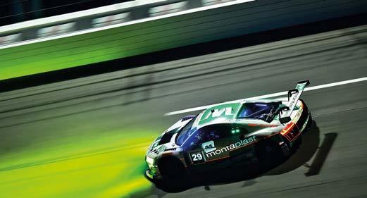


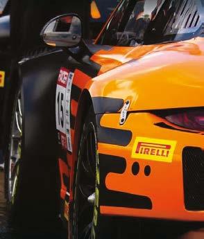


80 www.racecar-engineering.com OCTOBER 2022 Design • Analysis • Manufacture We specialise in the design and development of technologically advanced polymer products for use within motorsport, defence and industry. Our design activities are dominated by expert use of the latest Finite Element Analysis software. We manufacture high performance polymer products including: • Low ProfileCVboots • High performance PTFE Linedshaftseals • Bladder accumulators • Custompolymersolutions • AV mounts For moreinformationvisit: www.active-polymer.com Tel: +44(0)7756 515772 • Email: support@active-polymer.com ACTIVE POLYMER TECHNOLOGIESIncluding: Endurance Fuel Rig Scales Wireless Intelligent Fuel Timer Wireless Fuel & Air Temperature Sensors Tel: +44 (0)1844 216 057 Web: www.primarydesigns.co.uk Email: patbarrett@primarydesigns.co.uk Suppliers to championship winning Formula 1 teams and world record breaking supercar manufacturers. Our knowledge of exhaust design, alongside our expertise in the welding and fabrication of thin wall exotic alloys makes us the ideal partner to design and build high-performance racing exhausts for an extensive range of motorsport applications. Primary Designs are leaders in the design and manufacture of world-class high performance exhausts

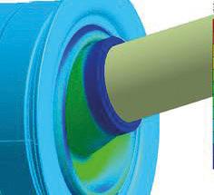


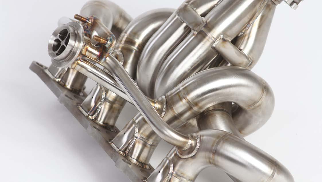


There’s plenty of future demand from motorsport as technical improvements are planned across most major series, while there are new series appearing across Europe and the USA. Meanwhile, the constant need for energyefficient, carbon reduction solutions is increasing and continues to create good business for many. And many of the international buyers that are involved in these exciting new opportunities will attend the CTS 2022 Show. Previous experience provides some guidelines and tips. Don’t wait for things to improve; move fast, particularly on prices; keep close to suppliers and customers; react quickly to their comments; be agile and flexible, open to new ideas and solutions; find and meet new suppliers and collaborators, perhaps even competitors, who can become valuable allies to meet these challenges.
benefit. Buyers are now looking for alternative suppliers as an insurance, which is good news for some as it opens up new relationships.
Top talent
The essence of our business demand is the entertainment which international and local motorsport, and high-performance mobility, provides to the public. Commercial motorsport income relies on sponsorship attracted by the substantial TV and online audiences which our sport generates which, in turn, pays for the essential engineering supplies from our world-class, specialised businesses.
The unexpected people problem can only be solved, quickly, by paying the best salaries possible and offering the most attractive employment conditions. This, of course, will increase selling prices, but nevertheless top-quality people are vital to meet development and delivery targets.
The well-recognised speed, worldclass quality and agility of our workforce has always been important to buyers. But to maintain this there is now an additional cost that will have to be met.
Winging it After just a few weeks, we have already sold nearly all exhibition space at our CTS 2022 Show on October 19/20 in the Silverstone Wing. Some are surprised by this immediate success – but we are not. Our research showed that our industry wanted us to make it easy for suppliers and buyers to meet together, and also that we attract new customers and collaborators from targeted industries.
During Covid, public demand for motorsport, largely led by Formula 1, grew exceptionally and during tough times we can expect this demand to be maintained. In addition, demand from defence is increasing due to activity prompted by the dire situation in Ukraine, and demand in the marine sector from the urgent need for innovative energy efficient, zero emission solutions.
For more information on the MIA, check out www.the-mia.com, or make contact directly via info@the-mia.com
The ongoing supply difficulties with both products and people are significant challenges calling for excellent management
October is the perfect time to secure business revenues from deliveries to be made in early 2023 for the season ahead – a real bonus. There are no entry or parking charges, no public access. Just legitimate trade visitors, a dinner for 500-plus industry guests, and an excellent new Hilton Garden Inn linked directly to the Show. The CTS 2022 Show is organised to benefit both you and our industry, please find out more at www.the-mia.com. Our sector’s supply and demand profile is unusual. The MIA serves companies in the unique business sector of high-performance engineering and motorsport, with links to automotive, defence, aerospace and marine.
BUSINESS TALK CHRIS AYLETT
The CTS 2022 Show takes place in the Silverstone Wing building on October 19/20, offering suppliers and buyers the chance to meet and forge long-lasting business relationships XPB
OCTOBER 2022 www.racecar-engineering.com 81
Flexible management
The ongoing supply difficulties with both products and people are significant challenges calling for excellent, flexible management, with no quick-fix solutions. Very little of our product goes directly to consumers, but it usually plays a part in an engineering solution. As input costs rise, so must selling prices – tough for buyers, but they have little option but to accept. They need the product, and to ensure that their vital suppliers stay in business – a genuine mutual
I am confident you will benefit from visiting the MIA CTS 2022 at Silverstone in October. It costs nothing to register to attend but guarantees you and your colleagues access to new business opportunities.
The MIA’s CEO looks forward to the CTS Show at Silverstone in October The opening words in most of the conversations I have with both UK businesses and my international friends these days are: ‘how’s business’. But the replies have never been more confused. All our businesses face exceptional times. Inflation has reach 10 per cent in the UK, with increased energy costs; higher wages to attract employees; and increasing costs of supplies amongst the causes. Experience shows our sector has been ‘last in and first out’ when general business downturns, so perhaps there’s hope for the same this time around? But the MIA prefers to take positive action now by meeting our community face-to-face and delivering activities they feel will bring success and counter negativity. We all know that winning comes from collaborative effort, with no place for excuses or time-wasters.
Wing commander

The circuits on which there have been issues in the WTCR are specific; either high degradation layout, high deg tarmac that particularly suits Formula 1 cars but which rips the heart out of the tyres of other racing series, or high kerbs. With the latter, the issue is exacerbated when cars are allowed to hop the kerbs, leading to further damage.
ANDREW COTTON Editor Although due care has been taken to ensure that the content of this publication is accurate and up-to-date, tested that are described herein, and their inclusion does not imply any form of endorsement. unsolicited but can accept no liability for their safe without the written permission of the is strictly prohibited. Racecar Engineering (USPS 007-969) is published 12 times per by +44 (0) 1795 419837
Gravel rash At the Spa 24 hours, again on Pirelli’s global GT3 tyre, there were a few punctures, but nothing too dramatic, which was not the pre-race prediction. Ride height changes, circuit changes and 66 cars taking the start seemed to suggest that there would be carnage. One team forgot to inflate a tyre before it was released from the pit, which was a new one on me. Others had punctures from stones in the gravel, though. The story was that the new gravel traps that line the track were supposed to be full of rounded stones, but a supply issue meant that only the stones closest to the kerbs were rounded; the rest of the trap was filled with sharper stones. But actually the biggest issue for Pirelli was the transition from gravel to kerb. Large differences in height were seen on the track walk, up to, I guess, four inches; high for a car looking to return to the track having run wide.
Michelin hasn’t had any major dramas, but in the US IMSA series the tyres are certainly well protected. Tyre pressure limits are prescribed, and monitored using TPMS after the tyres have come up to temperature. Camber limits are also in place, which means that the tyres are used pretty much in their prescribed operating windows. That leaves the manufacturer more free to explore performance, be that in lap time, operating window or longevity of tyre life.
Still, the main issue is that the teams will always take risks with the set-up. As one tyre engineer put it, running extreme set-ups is akin to not putting enough fuel in the tank to complete the stint. Yes, you will be faster, but not for the duration of the race.
It’s clear that any time a car is running with a flat tyre it’s the tyre manufacturer that will cop the blame. For sure, sometimes it is their fault, but teams have a habit of pushing the boundaries, pushing the equipment to a point outside its original design operating window in the pursuit of performance, and often that leads to a failure of some kind. They might take risks with camber settings, pressure settings, ride height settings, re-using a tyre that has been carried over from qualifying where it was damaged, or it could be the minimum weight of the car increasing. Most issues in life come from a combination of failures, and cars running around with flat tyres are pretty much victims of various circumstances, too.
Risky business
Chelsea Magazine Company in England. PIT CREW www.racecar-engineering.com To subscribe to Racecar Engineering, go to www.racecar-engineering.com/subscribe or email racecar@servicehelpline.co.uk telephone
• Racecar Engineering incorporating Cars & Car Conversions and Rallysport, is published 12 times per annum and is available on subscription.
the publisher can accept no liability for errors and omissions. Unless otherwise stated, this publication has not
News).
products or services
year
Last month I wrote about track limits with regard to the sausage kerbs that have caused such drama recently, but modern circuit design lends itself to drivers taking short cuts, or carrying more speed through a corner and running wide on the exit. But as Porsche found out at Le Mans, it can cost you a win if circumstances conspire against you.
return. © 2022 Chelsea Magazine Company. All rights reserved. • Reproduction (in whole or in part) of any text, photograph or illustration contained in this publication
By accepting advertisements in this publication, the publisher does not warrant their accuracy, nor accept responsibility for their contents. The publisher welcomes
Editor Andrew@RacecarEdCotton Email andrew.cotton@chelseamagazines.com Deputy editor Stewart @RacecarEngineerMitchell Email stewart.mitchell@chelseamagazines.com Sub editor Mike Breslin Art editor Barbara Stanley Technical consultant Peter Wright Contributors Mike Breslin, Lawrence Butcher, Gemma Hatton, James Kmieciak, Danny Nowlan, Photography James Moy Group sales director Catherine Chapman Email catherine.chapman@chelseamagazines.com Head of sales operations Jodie Green Email jodie.green@chelseamagazines.com Advertisement manager Lauren Mills Tel +44 (0) 20 7349 3796 Email lauren.mills@chelseamagazines.com Marketing executive Eleanor English Email eleanor.english@chelseamagazines.com Publisher Simon Temlett Managing director James Dobson Chairman Paul Dobson Editorial and advertising Racecar Engineering, Chelsea Magazine Company, Jubilee House, 2 Jubilee Place, London, SW3 3TQ Tel +44 (0) 20 7349 3700 Subscriptions Tel: +44 (0)1858 438443 Email: racecarengineering@subscription.co.uk Online: www.subscription.co.uk/chelsea/help Post: Racecar Engineering, Subscriptions Department, Sovereign Park, Lathkill St, Market Harborough, Leicestershire, United Kingdom, LE16 9EF Subscription rates UK (12 issues) £84 Europe (12 issues) £100/€120 ROW (12 issues) racecar@servicehelpline.co.uk£120/USD$165 Back Issues www.chelseamagazines.com/shop News distribution Seymour International Ltd, 2 East Poultry Avenue, London EC1A 9PT Tel +44 (0) 20 7429 4000 Fax +44 (0) 20 7429 4001 Email info@seymour.co.uk Printed by William Gibbons Printed in England ISSN No 0961-1096 USPS No 007-969 82 www.racecar-engineering.com OCTOBER 2022 Rubber is racing T
he issue of excessive tyre wear, usage and unreliability has popped up time and again, but in WTCR it has now reached something of a crisis point (see One team has withdrawn from the touring car series, a race has been cancelled and fingers are being pointed. Something has changed since last year that has led to problems, yet the tyres are the same, the cars are the same. Organisers have put in place measures to protect the tyres in the WTCR for the remainder of the season, including a weight reduction, extra practice sessions and more tyres. In the longer term the FIA and the WTCR organisers are working to find a permanent fix, and for that they have to delve deeper into the causes. This is not as straight forward as just blaming the tyre supplier. However, it is not only in WTCR that there are tyre problems this season. At the GT World Challenge race in France, Pirelli had a spate of failures, notably at the highspeed Signes corner. Fingers were pointed once again, but rival tyre manufacturers jumped to Pirelli’s defence and suggested that a large bump on the exit of the corner would have sent big shockwaves through the tyre and, towards the end of a stint on worn rubber, that could prove to be catastrophic.Pirelliitself noted that some of the tyres were damaged over the kerbs, they were run at too low pressures, or they were old tyres, used from another session first, and they may well have sustained damage then.
publisher
The main issue is that the teams will always take risks with the set-up
Endurance racing is a different world to F1, where the tyres have been designed by regulation to degrade to the point that it’s faster for a driver to pit and change than to continue. But even there, Pirelli once had to put in measures to restrict teams messing about with their tyres following catastrophic and embarrassing failures at the British GP.
manuscripts and illustrations
Did you know you can manage your subscription online? Oversee your print and digital subscriptions online today simply by signing up at https://www.subscription.co.uk/chelsea/Solo/ Stay up to date with the latest issues, update your personal details, and even renew your subscription with just a click of a button. Why tyre problems arise so often in top-line motorsport BUMP STOP