21 minute read
Dampers


Control freaks
Understanding the technology of dampers and the science behind their ongoing development
By JAHEE CAMPBELL-BRENNAN
In mechanical systems, vibrations and oscillations occurring due to external energy inputs are an inevitable reality. Thankfully, through a multitude of physical phenomena, this kinetic energy is converted into heat and sound energy. If this fundamental process didn’t occur, our world would be a very different, and resonating place.
Viscous damping is one such process that sees kinetic energy dissipated through the friction generated by the relative movement of molecules within a fluid medium.
Within powertrain components such as gearboxes, such processes are considered parasitic – a source of inefficiency we would like to do without – but one area in which we do harness viscous damping to our advantage is in the suspension system.
To a racecar, the suspension system’s main objectives are to manage weight transfer around the chassis and to control energy input from the road into the unsprung mass to manage variation in contact pressure at the tyre / track interface.
As the inherent structural damping within the metallic road spring is hugely insufficient in this application, the suspension system must employ methods through which to provide additional damping to control the oscillations of the sprung mass. By utilising viscous principles to provide a damping force proportional to the input velocity, modern automotive dampers do exactly this.
As the wheel moves relative to the body and the damper is displaced, oil is forced to flow through a series of small orifices and valves within the damper. The shearing stresses that result from this motion are resisted through intermolecular forces to generate an opposing force to dissipate these oscillations with an exponential decay.
A measure of the strength of these intermolecular forces is via the viscosity. More viscous oils demonstrate a stronger resistance to this flow, and damper oil is generally specified with a viscosity of between 10-20cSt (centistokes). For comparison, olive oil at room temperature is around 85cSt, so damper oil is relatively thin.
Modern, high-performance dampers have essentially converged on two main solutions: monotube and twin-tube concepts. These operate on the same basic principles but through different architectures, making each more suitable to certain applications than others.
Monotube dampers
The mechanically more straightforward monotube damper architecture encloses the working cylinder of the damper in a single layered ‘tube’ containing the oil.
As the wheel moves relative to the chassis due to driver or road inputs, a piston attached to the end of the input shaft is forced through the oil, causing it to flow under high pressure and high speed past various orifices and shim plates housed within the piston that provide resistance.
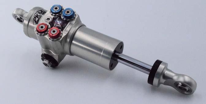
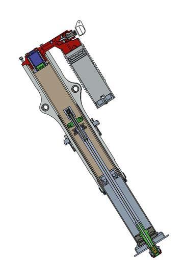
PKM
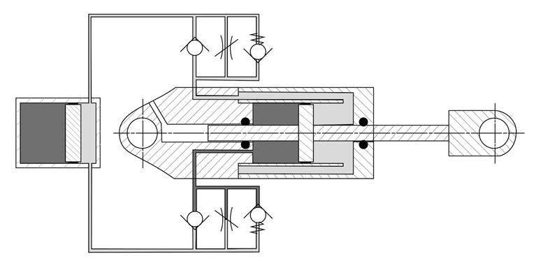
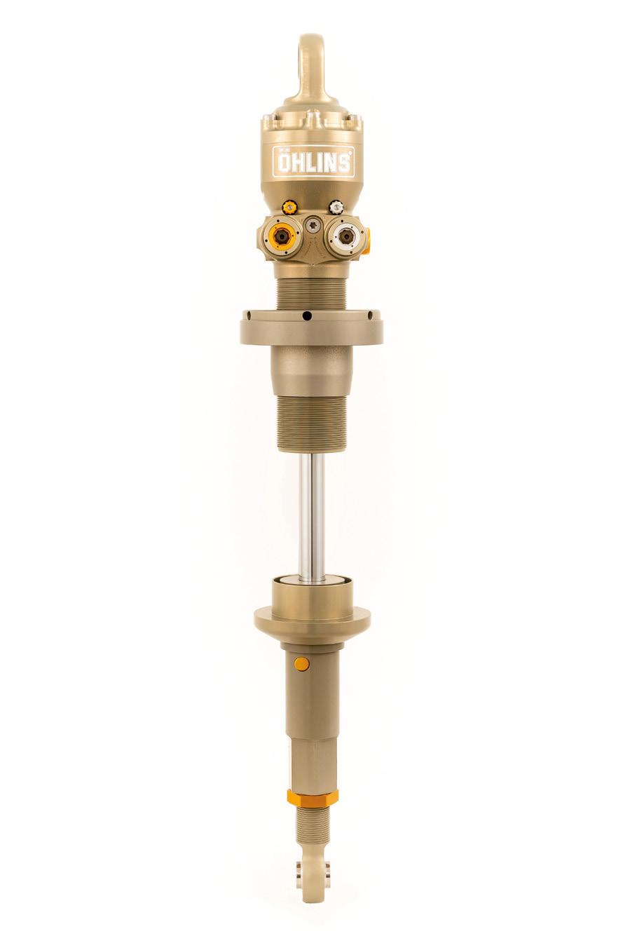
Section view of a through-rod twin-tube damper
Section view of a monotube damper
The piston is sealed against the internal diameter of the cylinder to prevent oil bypassing the valving and damper forces are modulated by adjusting the sizes and opening pressures of the orifices and various shim plates present.
An important, fundamental concept to understand about traditional damper architectures is that because the piston is connected to the damper shaft on one side only, the volume of the shaft in the working cylinder at full compression displaces a larger volume of oil than in full rebound.
As a solution to manage this, more advanced monotube dampers feature an external fluid reservoir to provide a volume for the displaced oil. Flow into the reservoir can also be controlled by a valve.
On the rebound stroke, the high forces generated by fast wheel movements can cause very low pressure in the downstream side of the piston. If the pressure within the damper fluid falls below the vapour pressure, cavitation occurs as bubbles of vapour form, and subsequently burst as pressure rises again. This is detrimental on two fronts. It can cause damage to adjacent components by creating shockwaves, and it also introduces additional compressibility into the damper fluid, which dramatically changes its performance.
To maintain a minimum pressure within the fluid and hold off cavitation, expansion reservoirs in monotube dampers feature a nitrogen gas volume pressurised at up to 20bar and separated from the oil by a diaphragm to exert a positive pressure on the oil.
Twin-tube dampers
Twin-tube dampers work in much the same way as monotubes. The key differentiator is the main cylinder of the damper is ‘sleeved’ by an additional outer cylinder, which leads to a different valving philosophy.
In twin tubes, the piston is often solid so, instead of providing the valving, it serves only as a mechanism of pumping fluid through valves located elsewhere on the fluid circuit. The secondary outer tube is present to provide the rebound volume with a flow path into this valving as fluid is pumped around during damper travel.
By freeing the piston of its valving obligations, twin tubes can offer the advantages of greater control of the damper’s response. The lower pressure differentials resulting from this approach also reduce the propensity of the damper for cavitation.
‘If you reduce the risk of cavitation in the dampers, it means you’re able to run a lower nose (inflation) pressure,’ explains Paul-Etienne Berthe, co-founder and chief of design at PKM, a company who produce motorsport dampers, specialising in LMP platforms. ‘For example, with twin-tube dampers you can run 5bar or less nose pressure, while you need around 20bar with standard monotube systems. This means you can have a much lower pre-load on the seals and reduced friction.’
The asymmetries in volumes displaced by each stroke of the piston in traditional monotube and twin-tube systems is always sub optimal. The additional fluid displaced in compression increases the oil volume in the reservoir, which means the gas volume must compress. In this process, the movement of the diaphragm introduces additional friction and resistance to compression movement.
Friction is detrimental to the damper for its influence into initial response, where subjectively it’s experienced as ‘harsh’ quality. This is not preferential for either tyre grip or tyre life as it increases the energy into the tyre. Less friction is always better.
Because of this, the twin-tube concept has been further developed to feature what’s commonly referred to as a throughrod design, in which the damper shaft extends through the piston and right to the top of the working oil volume. With this architecture, the same volume of fluid is maintained in the cylinder at all points in the damper’s operation.
By displacing equal volumes of fluid in each section of the cylinder, the pressure drop either side of the piston is minimised. And because the gas volume is not disturbed, friction introduced by diaphragm movement is eliminated.
‘With our TTX twin-tube designs, the valves can be small compared to the piston diameter, and a lot of oil is moved at a high speed, which is great for flow control. This is beneficial with cars using pushrods where a quick response is needed,’ notes Jonas Jarlmark Näfver, senior manager of mechatronics and vehicle performance at Öhlins. ‘We use both monotube and twin-tube dampers, depending on what we are trying to achieve and what traits the vehicle is more in need of.’
Generally, monotubes are preferable where low compression forces and lower adjustability is needed, while twin-tube designs are preferable where compression forces are high and more adjustability a requirement.
Damper tuning
Regardless of the chosen architecture, to tune the damping for an optimal response over the working speed range, motorsport dampers have adjustable valving, which in twin-tube designs generally comprises a mixture of needle and poppet valves.
The response of motorsport dampers is divided into two discrete operating regions – the high-speed region and the low-speed region.
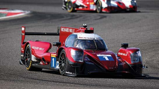
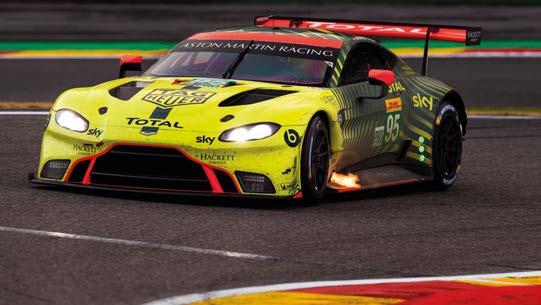
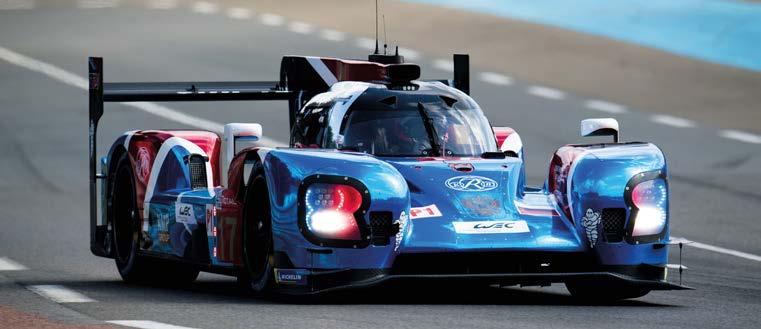
Low-speed damping – generally occurring at speeds less than 0.1m/s – is associated with a ‘crisp’ turn-in response, as this PKM-equipped Oreca 07 Le Mans Prototype shows Kerb strikes, characterised by violent, high speed damper input, need special treatment. Blow-off valves do the trick, as this Aston Martin with Öhlins dampers proved at Le Mans
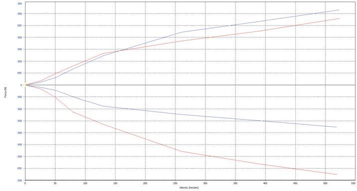
Fig 1: F-V curve of a digressive, track-based damping set-up
High-end dampers provide a customisable damping response over five distinct speed ranges: low-speed compression and rebound, high-speed compression and rebound and the ‘blow-off’ range applying to super high-speed compression inputs.
Low-speed damping generally applies at speeds <0.1m/s and is associated with controlling the motion of the body in response to driver inputs. It’s important to the perceived driver feel of the car, and also the rate of loading of the tyres during weight transfer.
Conversely, high-speed damping is concerned with damper speeds >0.1m/s, which is the region concerned with inputs from the track profile and control of the chassis following larger impacts such as kerb strikes. This is the region of damping with most input into the variations in contact pressure experienced at the tyre / road interface, and is very important in modulating the energy input into the tyre.
‘It’s easy to figure out the appropriate valving boundaries between each speed range,’ says Jarlmark Näfver. ‘If you have the driver just make some steering angle sweeps on track, the damper speeds you measure effectively define the low-speed range, while anything above this is due to road profile and kerbs, and falls in the high-speed range.’
The blow-off range comes into play in very high-speed inputs such as kerb strikes. Without a distinct damper response for this range, the damping forces would be extremely high and a lot of energy would be communicated into the chassis, unsettling the car.
‘We use blow-off valves on our dampers where we expect quite significant kerb strikes, essentially on real high velocity and high amplitude inputs. Their function is to rapidly drop off the damping force where it’s not needed and allow the wheel to conform to the kerb,’ continues Jarlmark Näfver.
The response of a particular damper is quantified using a piece of equipment called a damper dynamometer, which subjects it to a range of input speeds and measures the magnitude of the force it generates. The data from these machines is provided in terms of a force vs velocity (F-V) curve.
Damper response
The ideal damper response in terms of the forces generated within each speed range, or damper curve, varies for different applications, and is based on the high and low-speed damping requirements of the individual car at a particular track.
The interaction of forces across the damper speed range produces either a digressive curve (Figure 1), where the gradient trends to decrease with increasing velocity, a progressive curve (Figure 2), in which the gradient trends to increase with increasing velocity or a linear ‘curve’, which maintains the same gradient across the speed range.
The masses and inertias seen in circuitbased racecars, combined with high lateral
Force (N)
Velocity (mm/sec)
Force (N)
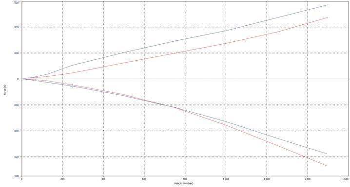
accelerations and smooth track surfaces, generally dictate a high amount of lowspeed damping to control the body and a relatively more constant high-speed damping force. This produces a digressive curve.
Off-road racing, on the other hand, where the forces are lower, requires less low-speed damping and a supple suspension at midspeed inputs to absorb higher amplitude bumps, but a high force to adequately absorb jump impacts and other excursions. This generally results in a progressive curve.
The different masses and inertias involved in compression and rebound also drive asymmetric damping requirements, so the valving requirements differ in magnitude for each direction of travel. Regardless of the specifics, it’s important the damper dissipates equal amounts of energy in rebound and compression, so the target is to ensure this condition is maintained as much as possible.
Bump stops
With the mass of the vehicle, at the extremes of compression travel the force with which the damper bottoms out at the end of its travel can be significant, especially landing from jumps and passing over kerbs. To protect the damper itself, and introduce some element of response control in this range of operation, dampers use bump stops.
In circuit racing applications, these are simple elastomer parts that sit at the bottom of the damper shaft. Once engaged, their spring rate is very non-linear and rises sharply to provide the required deceleration. Bump stops can be selected with different rates dependent on the magnitude of engagement seen at particular circuits, but they also serve an important function for the aerodynamic platform.
‘As a general principle, we always try to keep our dampers out of the bump rubbers as they add a lot of non-linearity and, by relying on them to generate chassis performance, you’re losing grip,’ explains Jarlmark Näfver. ‘If you need the chassis control and can sacrifice some ultimate grip, as is the case with high aero cars in LMP and Formula 1, for examples, the bump stops do serve an additional function.’
The spring rates required of a system to support a chassis at the correct ride height, with thousands of kg of aero load at the end of the Mulsanne Straight at Le Mans, for example, would compromise grip levels in the low-speed section of the tracks significantly. Using the bump stops as a method of limiting wheel travel and maintaining ride height when the aero load overwhelms the road spring in this manner is therefore very useful, and allows the use of softer road spring rates for best tyre grip.
‘At Daytona, for example, we even use asymmetrical bump stops,’ adds Thierry Gravier, another co-founder of PKM. ‘The car travels through some very highspeed, high-g, banked curves where it can experience a large amount of body roll. This is a bad situation for the aero platform, so to keep the underside of the car parallel with the track we use asymmetrical stops left to right to limit the roll angle at key corners.’
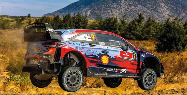
In off-road and rally dampers, the extremely high damper velocities seen following jump landings and other high amplitude compressive inputs provide a completely different set of boundary conditions for the bump stop, which requires a very different approach.
Öhlins
Öhlins supplies through-rod, twin-tube dampers for the Next Generation NASCAR series In high aero categories, such as the old LMP1 era of the WEC pictured here, bump stops provide a method of maintaining a car’s minimum ride height when travelling at high speed, while at the same time allowing the use of soft springs for low-speed grip
Hydraulic bump stops
In this case, hydraulic bump stops are used, which can provide as much as 50mm travel in some cases. Through their nature, the
hydraulic bump stops also allow engineers to design unique, adjustable F-V curves separate from the main damper’s action. A damper within a damper if you will.
‘The hydraulic bump stops are externally adjustable, which allows us to set its performance over the different stages of travel. The adjustability changes the shape of the curve to adjust the force both at the beginning, middle and end of the bump stop’s range,’ notes Berthe.
The performance of the bump stop in this application, interestingly, is also dependent on both velocity and displacement.
‘The hydraulic bump stops in our rally dampers are actually adjusted using something more like a spool than a needle valve. This means we drill different orifices for different displacement positions, and you can have a completely different curve [digressive / progressive] for each stage of its travel,’ complements Gravier.
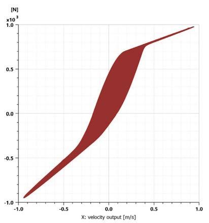
Damper hysteresis
The viscous forces within the oil are the primary means of dissipating energy, but losses occur in many parts of the damper, including unintended flexibility within the body and other structural parts, compressibility within the damper oil and cavitation.
This form of energy dissipation always means that the energy of the compression stroke does not equal the energy of the rebound stroke. The energy dissipated within each cycle is identified as hysteresis.
The hysteresis displayed by a damper determines the phase of its response, which can either ‘lag’ or ‘lead’ the input. If the gradient of the initial force is high, this is described as a phase leading damper, the converse is described as phase lagging.
Phase is also influenced by valving behaviour so, by controlling this, damper engineers can even use phase behaviour to their advantage.
‘As an example, if the phase is leading the velocity, the damper initially generates an amount of inertia that can be used to control the chassis in a similar sense as an inerter would, if you know what you’re doing,’ explains Jarlmark Näfver. ‘In this case, the transient response time is minimised, which can tighten up turn in.’
On the other hand, a lag in phase gives a somewhat more displacement-focused initial response, as the spring provides the majority of the force in the first moments. It’s a very small amount of time, just milliseconds, but the effect can be quite pronounced.
‘A phase which is lagging in a controlled manner can be beneficial for rally cars over certain surfaces, such as hard gravel,’ continues Jarlmark Näfver.
Control in this manner can be implemented by using valves that are slow to open, giving a very high force with only a little velocity for that initial transient period until nominal force is reached.
Traditionally, damper design and specification have been viewed from the outside as somewhat mysterious, with effective dampers being the result of a certain amount of trial and error, experience and, apparently, luck.
In today’s engineering environment, however, simulation has pushed our understanding of the principles of fluid movement inside the damper and what we can achieve magnitudes forward.
As in many engineering disciplines, being able to rely on accurate simulation models has cut large amounts of time and expense out of the development process, in some cases enabling the prototype phase to be entirely digitised.
Development process
A logical damper development process now starts at damper specification, using software-based models to approximate the appropriate ‘window’ of damping required for a specific application. In order to do this, the masses, inertias, weight distributions, aerodynamic loads, inertial forces and suspension geometries must be known.
If the damper is not being developed on the drawing board alongside the vehicle, these parameters must at least be approximated before simulation can begin.
‘Simulation today correlates very well with what we see on lab facilities such as the four or seven-post rig, but we also have the benefit of being able to do more. For example, we can recreate certain lateral forces and driver inputs you don’t have on a shaker rig, so this is more representative of the real environment,’ adds Jarlmark Näfver. ‘Having the real, physical damper has been an advantage in the past, but damper modelling techniques can be so detailed that it’s not an issue today.’
After validation on a damper dyno, next step is to head to the track for a first ‘real’ test. Simulation is not quite at the point where the real world can be modelled with complete fidelity, so track time in the physical operating environment is invaluable.
Objectives here are to verify the simulation models and that the damping values are in the correct range to give enough adjustability for the different operating conditions experienced, or even to suit a particular tyre.

The difference in forces generated during the cycle of compression and rebound travel indicates the level of hysteresis of the damper – the red area represents the energy dissipated by the damper over the cycle
Where simulations are not practical or feasible, for example where the full vehicle model does not exist, there is more emphasis on lab testing to validate any assumptions made at the initial design phase. Here, the suspension shaker rig is a method of quantifying wheel loads and understanding a suspension set-up in a little more detail.
‘Generally, our customers use the seven-post rig to complement their track testing, in the sense that you might be able to get 90 per cent of the way towards a set-up at the track but, to really fine tune the car within the window you found, the rigs can be great to put some numbers on the set-up options,’ explains Gravier.
Environmental effects
Once performance development is finalised, the damper must prove itself over distance, so the focus then becomes about robustness and durability.
Servicing intervals of 6000km are fairly standard in motorsport dampers but, with certain endurance races running very close to this distance (5410km is the distance record set at the 2010 Le Mans 24 Hours), it’s a lot to ask of the technology to maintain its performance across the full interval. Performance diminishes as oil degrades and components wear.
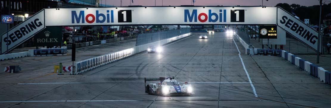
‘The main problem for endurance races is maintaining consistent damping over the whole race. For really aggressive races, such as the Sebring 12 Hours, we can see very significant changes in damper performance over the distance. The energy going into the damper is so high, the temperatures and shearing forces just degrade the oil,’ says Gravier. ‘Le Mans, on the other hand, is a different challenge. It’s a lot of time at full throttle and high rpm, which means a lot of vibration energy. This can be somewhat of an issue as it wears the internal valving components.’
While simulation software is an answer for much of the development process, phenomena like vibration, temperature, oil ageing and other environmental circumstances are difficult to model and are very specific to each application. This means some assessments can only be made at the track.
‘The LMP2 regulations were changed some years ago and a different engine was used, which introduced a very different vibration profile into the dampers. We were finding a lot of unusual wear and in one instance the damper body was being machined by a mating part. This was quite a complex issue and resulted in a number of material and design changes,’ notes Gravier. ‘This is very difficult to recreate in the lab, and why track testing is still so important.’
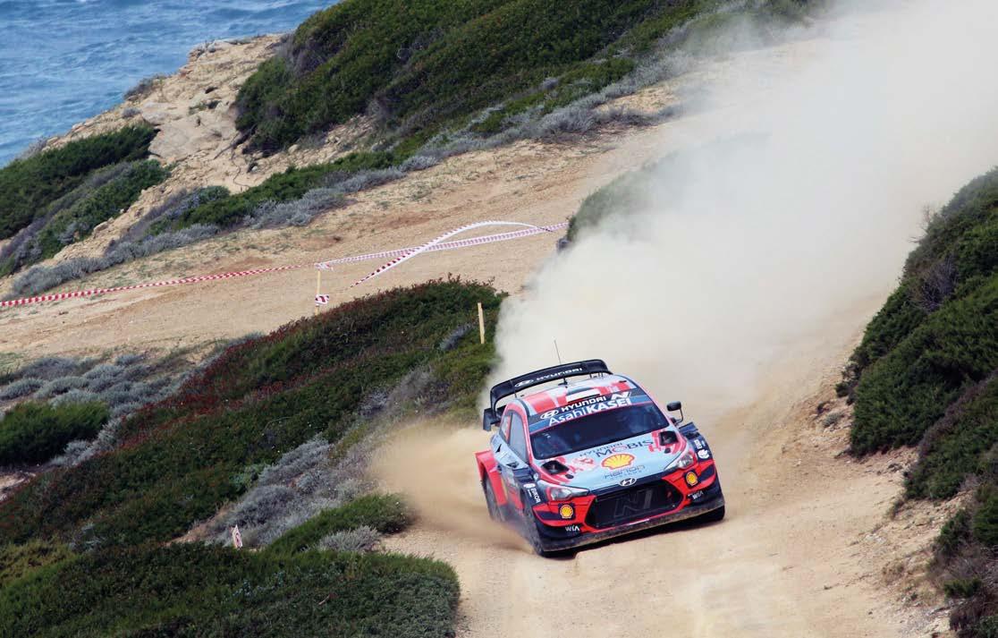
The extreme environments seen in off-road racing take this further still. The level of energy input into a damper over a stage in the Dakar, or WRC, is really quite astonishing. Intermolecular friction is enough to heat the damper oil to well in excess of acceptable temperatures and shearing forces alone are enough to cause degradation of its properties.
‘In the dampers we used to run in the Dakar rally, temperatures could sometimes reach 180degC as they’re dissipating so much energy. Maintaining stable performance can get troublesome in this environment so we used to run cooling fins on the damper bodies to try and manage this,’ explains Jarlmark Näfver
The immediate effect of high temperatures is the oil reduces in viscosity. To offset this, various valves within dampers can be designed such that the thermal expansion experienced works to close certain orifices, keeping the flow rate consistent and performance stable over the temperature range.
‘Damper oil can expand by up to approximately eight per cent in some cases, so there must be space in the reservoir to account for this,’ adds Berthe.
Modern damper oils are synthetic and internal and external sealing technologies are of a polymer construction, but much above 120degC and the lubricative properties of the oil break down, which causes high wear. It’s therefore vitally important for race teams to keep on top of servicing to prevent this kind of damage occurring.
Future developments
There’s no doubt digital simulations have allowed us much more insight into the physical principles involved with automotive dampers, and the biggest developments in the last decades have coincided with advancements in understandings released by simulation.
These have been capitalised upon by innovative design and advances in materials and manufacturing processes to allow better control of the damper response, but the desire for more control still burns.
Further control means damping forces can be tuned even more precisely, so much so the damper ‘curves’ don’t have to follow a curve at all. Being able to completely remove the compression damping as the wheel impacts the kerb would be very attractive, as would the ability to modulate the damping depending on the sector, or corner, of the lap being driven.
As much as large sectors of the motorsport industry would jump at the chance to implement active damping technologies, the future of damper development very much falls on the direction of regulations, so it still looks like motor racing will be relying on the traditional hydraulic damper for some years yet.
Endurance racing pushes dampers to the limits. Their response can change dramatically from the start to the end of a long race such as the Sebring 12 Hours pictured here in 2019