EROSION AND SEDIMENT CONTROL MANUAL
111 E Maple St Independence, Missouri
Revised July, 2019

Revised July 2019 1
PREFACE AND DISCLAIMER PREFACE
The purpose of the Manual is to provide a comprehensive and detailed approach for preventing erosion and controlling sediment on land disturbance sites. It has been updated to include the latest information regarding materials and installation practices that have proven effective over the past years. There are numerous other resources available online.
DISCLAIMER
The Erosion Prevention and Sediment Control Guidelines Manual were developed for the sole purpose of providing the Erosion Prevention, Run-off Management, Sediment and Tracking Controls, and Pollution Prevention Best Management Practices (BMP's). The contents of this manual should not be interpreted as representing the policies or recommendations of other referenced agencies or organizations. The mention of trade names, products, or companies does not constitute an endorsement. Periodic updates will be made as materials, practices, and policies change within the industry and are made available.
Revised July 2019 2
Revised July 2019 3 TABLE OF CONTENT Introduction 4 General Design Guidelines 5 I. Erosion Control Preservation of Existing Vegetation 9 Mulching 11 Seeding 13 Hydro seeding 16 Sodding 18 Erosion Control Blankets 21 Turf Reinforcement Mat 24 Streambank Stabilization 26 II. Runoff Management Check Dams 29 Earth Berms and Drainage Swales 32 Water Diversion 35 Slope Drains 39 Dewatering Operations 42 III. Sediment Control Vegetated Filter Strip 46 Silt Fence 48 Compost Filter Berms 51 Sediment Basin 53 Inlet Protection-Curb 58 Street Sweeping and Vacuuming 61 Construction Exit 63 Non-Sediment Pollution Control (Housekeeping) 66
These guidelines are intended to provide the designer, contractor and builder with design criteria and minimum standards for the installation of erosion and sediment controls to comply with the Erosion and Sediment Control Regulations. The regulations were enacted to protect the health, safety, and property of the citizens and to help protect area water resources from pollution due to erosion and transportation of sediment. The regulations are applicable to all land development and land disturbance activity within the regulated MS4 area where the area of disturbance is more than one acre. The regulations require that no person cause or allow sediment to be deposited in any public street, public land, or on any property not under their control as a result of land disturbance from construction activities.
You can comply with the regulations by meeting the following objectives:
a. Minimize the area disturbed by construction and development;
b. Provide for containment of sediment until areas are stabilized;
c. Stabilize disturbed areas as soon as practical after project completion; and
d. Provide permanent erosion, drainage, and detention controls.
Revised July 2019 4
Introduction
GENERAL DESIGN GUIDELINES
Erosion is a natural process where soil and rock are loosened and removed. Natural erosion normally occurs at a very slow pace, but when land is disturbed on a construction site, the erosion rate often increases significantly. When erosion occurs on a construction site and runoff carries sediment off the site, there is often a negative impact on downstream drainage systems such as water quality. The purposes of erosion and sediment controls are to minimize the amount of erosion that occurs as a result of construction activity and to prevent the sediment that is produced from leaving the property. Effective erosion and sediment control requires that the soil surface be protected from the erosive forces of wind, rain, and runoff and that the eroded soil be captured and retained onsite. The following principles are effective when they are integrated into a system of control practices and management techniques to control erosion and prevent sedimentation offsite
When designing sediment and erosion controls, it is necessary to determine whether there is sheet flow or concentrated flow of storm water on the property. Sheet flow occurs on gently sloping land without defined drainage ways. The storm water tends to disperse evenly across the property, although the drainage may be in one direction due to the overall slope of the property. Concentrated flow occurs on property where there are defined drainage ways that may range from gentle swales to clearly defined waterways. It is possible to have a combination of sheet flow and concentrated flow on the same property.
Erosion Protection
Proper planning will help identify potential erosion problems, particularly highly susceptible areas, such as areas of concentrated flow. Removing the vegetative cover and altering the soil structure by clearing, grading, and compacting the surface increases an area's susceptibility to erosion. Scheduling can be a very effective means of reducing erosion. Schedule construction activities to minimize the exposed area and the duration of exposure. Apply stabilizing measures as soon as possible after the land is disturbed. Per the operating agreement, Department of Natural Resource requires that ground cover be areas where work is not performed for a specified time frame. These time frames can be found in the operating permit .Plan and implement temporary or permanent vegetation, mulches, or other protective practices to correspond with construction activities. Protect channels from erosion forces by using protective linings and the appropriate channel design. Consider possible future repairs and maintenance of these practices in the design. In scheduling, take into account the season and the weather forecast Clearing existing vegetation reduces the surface roughness and infiltration rate and increases runoff velocities and volumes. This is particularly a concern in areas of concentrated flow. Use measures that break the slopes to reduce the problems associated with concentrated flow volumes and runoff velocities. Practical ways to reduce velocities include conveying storm water runoff away from steep slopes to stabilized outlets, preserving natural vegetation where possible, and mulching and vegetating exposed areas immediately after construction.
Revised July 2019 5
Sediment Containment
Even with careful planning some erosion is unavoidable, and the resulting sediment must be trapped on the site. In areas where runoff occurs primarily as sheet flow, containment of sediment is relatively simple. In these areas, temporary containment devices may be sufficient. Where concentrations of flow occur, containment of sediment becomes more difficult as the rate and volume of flow increase. In these areas, more extensive or permanent control devices need to be provided. Areas of steep topography and cut or fill slopes need to be given special consideration. Due to the environmental sensitivity of streams, rivers, losing streams, sinkholes, and other Karst topographic features, special consideration also needs to be given to these areas. Plan the location where sediment deposition will occur and maintain access for periodic removal of accumulated sediment. Protect low points below disturbed areas by building barriers to reduce sediment loss. Sediment traps and basins should be constructed before other landdisturbing activities occur.
Pre-Construction versus Post-Construction Controls
Pre-construction controls, such as silt fences, erosion control blankets, etc., are provided for the purpose of controlling erosion and containing sediment until construction is complete. Pre-construction controls are not needed after the area is stabilized.
Post-construction controls consist of riprap, concrete trickle channels, detention basins, etc., which will remain in place through the life of the development. It is possible for the same structure to serve both a pre-construction and post-construction purpose.
Maintenance Regular inspection and maintenance of Best Management Practices (BMPs) are vital to the performance of erosion and sedimentation control measures. If not properly maintained, some practices may cause more damage than they prevent. Always evaluate the consequences of a measure failing when considering which control measure to use, since failure of a practice may be hazardous or damaging to both people and property. For example, a failure of a large sediment basin can have disastrous results, and low points in dikes can cause major gullies to form on a fill slope. It is essential to inspect all practices to determine that they are working properly and to ensure that problems are corrected as soon as they develop.
BMP Descriptions and Design Guidance
The following principles are effective when they are integrated into a system of control practices and management techniques to control erosion and prevent sedimentation offsite. As a matter of practicality, proprietary erosion and sediment control products are not specifically identified herein. However, the County encourages the use of these products when designed, specified and installed in accordance with manufacturer’s recommendations. Sufficient details related to these products should be supplied to facilitate the review of the plans to ensure the suitability of the practice. The following is not meant to provide an exhaustive list of all acceptable erosion and sediment control practices accepted by the county, only as a general guidance document. There may be instances where certain erosion control designs are beyond the scope of general civil engineering knowledge. Specifically, natural stream stabilization and/or restoration should only be
Revised July 2019 6
done with specific expertise and experience with these systems. This manual is not intended to convey such a level of knowledge and therefore will not address this level of complexity.

Revised July 2019 7
Figure 1. Silt Fences are placed at the perimeter of the job site to capture and prevent sediment from leaving the site.
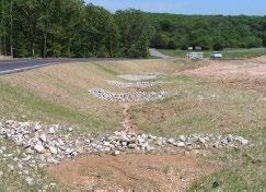
Figure 2. Rock Check dams can reduce water velocities in areas of channelized flow.
EROSION CONTROL
Revised July 2019 8
CATEGORY: Erosion Control
USE GROUP: Post-Construction
PRESERVATION OF EXISTING VEGETATION
DEFINITION AND PURPOSE:
Preservation of existing vegetation and topsoil is the identification and protection of desirable vegetation that provides erosion and sediment control benefits.
APPROPRIATE APPLICATIONS:
Preserve existing vegetation at areas on a site where no construction activity is planned or will occur at a later date.
CONDITIONS FOR EFFECTIVE USE:
Protection of existing vegetation requires planning, and may limit the area available for construction activities.
WHEN BMP IS TO BE INSTALLED:
Preservation of existing vegetation shall be provided prior to the commencement of clearing and grubbing operations or other soil-disturbing activities in areas identified on the plans to be preserved.
STANDARDS AND SPECIFICATIONS:
Minimize the disturbed areas by locating temporary roadways to avoid stands of trees and shrubs and to follow existing contours to reduce cutting and filling. Mark vegetated/natural resource areas to be preserved with temporary fencing that are at least 1 meter (3.2 ft.) tall. The fence post spacing and depth shall be adequate to completely support the fence in an upright position through duration of project. Construction materials, equipment storage, and parking areas shall be located where they will not cause root compaction. Keep equipment away from trees to prevent trunk and root damage. Employees and subcontractors shall be instructed to honor protective devices. No heavy equipment, vehicular traffic, or storage piles of any construction materials shall be permitted within the drip line of any tree to be retained. Trenching shall be as far away from tree trunks as possible, usually outside of the tree drip line or canopy. The ends of damaged or cut roots shall be cut off smoothly.
OPERATION AND MAINTENANCE PROCEDURES:
During construction, limits of disturbance shall remain clearly marked at all times. If damage to protected trees occurs, the injured tree shall be attended to by an arborist, as determined by city staff
SITE CONDITIONS FOR REMOVAL:
Temporary fencing shall be removed after final stabilization of the site has occurred.
TYPICAL DETAILS: Not Applicable
Revised July 2019 9
CATEGORY: Erosion Control
USE GROUP: Pre or Post-Construction
MULCHING
DEFINITION AND PURPOSE:
A layer of organic material designed to protect exposed soil or freshly seeded areas from erosion by eliminating direct impact of precipitation and slowing overland flows. Mulch materials may include, but are not limited to, such things as grass, hay, straw, wood chips, wood fibers, and shredded bark.
APPROPRIATE APPLICATIONS:
Typically used for soil stabilization as a temporary surface cover on disturbed areas until soils can be prepared for revegetation and permanent vegetation is established.
CONDITIONS FOR EFFECTIVE USE:
Type of Flow: Sheet flow only
The use of appropriate mulch will help ensure the vegetation is established under normal conditions and is essential to seeding success under harsh site conditions. General mulch recommendations to protect disturbed soils from raindrop splash and sheet flow include: straw applied at 2-2.5 tons/acre, wood fiber or wood cellulose applied at 0.5-1 ton/acre, wood chips applied at 5-6 tons/acre, and bark applied at 35 yard 3/acre. Where slopes are 33 percent (3:1) or greater grade, hydraulic mulch-bonded fiber matrix, erosion control blankets, or turf reinforcement mats are required.
WHEN BMP IS TO BE INSTALLED:
Immediately after grading landscaped areas or seeding other areas.
STANDARDS AND SPECIFICATIONS:
Install upstream BMPs to protect area to be mulched. Rough grade area and remove all debris larger than 1 inch if area is to be vegetated and mowed in the future, larger than 2 inches if area is to be permanently mulched. If area is to be seeded, follow requirements of Seeding. Spread mulch evenly and anchor by punching it into the ground, using netting, or tacking with liquid binder.
OPERATION AND MAINTENANCE PROCEDURES:
Inspection should be frequent in accordance with storm water management plan until adequate vegetation is established; annually for permanent mulch. Protect from vehicular and foot traffic. Repair damaged degraded or eroded areas-reseed as needed and replaces mulch.
SITE CONDITIONS FOR REMOVAL:
Temporary mulch should be removed when adequate vegetation is established.
TYPICAL DETAILS: Not Applicable
Revised July 2019 10
CATEGORY: Erosion Control
USE GROUP: Pre or Post-Construction
SEEDING
DEFINITION AND PURPOSE:
Establishment of vegetation by spreading grass seed designed to protect exposed soil from erosion by eliminating direct impact of precipitation and slowing overland flow rates. Once established, the vegetative cover will also filter pollutants from the runoff.
APPROPRIATE APPLICATIONS:
Exposed soil after a phase of rough or finish grading has been completed, or areas where no activity will occur for 14 days.
CONDITIONS FOR EFFECTIVE USE:
Type of Flow: Sheet flow and concentrated flow (additional stabilization is necessary).
WHEN BMP IS TO BE INSTALLED:
Immediately after rough or finished grading is completed.
STANDARDS AND SPECIFICATIONS:
Install upstream BMPs to protect area to be seeded. Complete grading and remove all debris larger than 1 inch. Loosen compacted soils to a depth of 4 inches. Groove or furrow on the contour if necessary. Spread loose topsoil at a depth of 4 inches. Mix soil amendments (lime, fertilizer, etc.) into the top 4 inches of soil. Plant seed ¼ to ½ inches deep using a cyclone seeder, drill, cult packer seeder, or hydro- seeder. Roll lightly to firm surface. Cover seeded area with mulch. Install additional stabilization (erosion control blankets, netting, bonded fiber matrix, etc.) on slopes steeper than 3:1 and in areas of concentrated flow. Water immediately-enough to soak 4 inches into the soil without causing runoff.
OPERATION AND MAINTENANCE PROCEDURES:
Inspection frequency should in accordance with storm water management plan. Protect seeded areas from vehicular and foot traffic. Reseed and mulch areas that have not sprouted within 21 days of planting. Repair damaged or eroded areas and reseed/mulch and stabilize as needed. Do not mow until 4 inches of growth occurs. During the first 4 months, mow no more than 1/3 the grass height. Seeded areas should be maintained for one year following permanent seeding to ensure a healthy lawn.
SITE CONDITIONS FOR REMOVAL:
Does not require removal, temporary vegetation may be removed prior to work returning to an area.
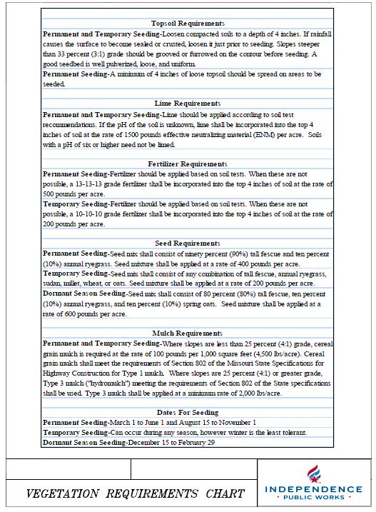
TYPICAL DETAILS; See attached Vegetation Requirements Chart
Revised July 2019 11
Revised July 2019 12
CATEGORY: Erosion Control
USE GROUP: Pre or Post-Construction
HYDROSEEDING
DEFINITION AND PURPOSE:
Hydro seeding typically consists of applying a mixture of seed, wood fiber, fertilizer, and stabilizing emulsion with hydro-mulch equipment, which temporarily protects exposed soils from erosion by water and wind.
APPROPRIATE APPLICATIONS:
Hydro-seeding is applied on disturbed soil areas requiring temporary protection until permanent vegetation is established or disturbed soil areas that must be re-disturbed following an extended period of inactivity.
CONDITIONS FOR EFFECTIVE USE:
Type of Flow: Sheet flow only.
Hydro seeding may be used alone only when there is sufficient time in the season to ensure adequate vegetation establishment and erosion control. Otherwise, hydro seeding must be used in conjunction with a soil binder or mulching in accordance with the associated specifications as outlined in this manual.
WHEN BMP IS TO BE INSTALLED:
Immediately after completion of a phase of grading.
STANDARDS AND SPECIFICATIONS:
To select appropriate hydro seeding mixtures, an evaluation of site conditions shall be performed with respect to: soil conditions, site topography, season and climate, vegetation types, maintenance requirements, sensitive adjacent areas, water availability, and plans for permanent vegetation. Hydro seeding can be accomplished using a multiple-step or one-step process. The multiple-step process ensures maximum direct contact of the seeds to soil. When the one-step process is used to apply the mixture of seed, fiber, etc., the seed rate shall be increased to compensate for all seeds not having direct contact with the soil. Follow-up applications shall be made as needed to cover weak spots.
OPERATION AND MAINTENANCE PROCEDURES:
All seeded areas shall be inspected for failures and re-seeded, fertilized, and mulched within the planting season, using not less than half the original application rates. Inspection frequency should be in accordance with storm water management plan.
SITE CONDITIONS FOR REMOVAL:
Typically left in place to degrade naturally.
TYPICAL DETAILS:
Not Applicable
Revised July 2019 13
CATEGORY: Erosion Control
USE GROUP: Post-Construction
SODDING
DEFINITION AND PURPOSE:
A ¾ inch to1 inch mat of vigorous turf, free from disease, insects and weeds. Sod prevents raindrops from disrupting the soil structure and causing erosion. Sod slows water runoff and acts as a filter when sediment laden runoff crosses over the sodded area.
APPROPRIATE APPLICATIONS:
Typically installed in areas requiring immediate erosion protection, such as swales or detention ponds and as filter strips, around inlets, and adjacent to curbs. Also installed in areas requiring immediate aesthetic appearance or function such as entrances to new subdivisions and off site construction areas.
CONDITIONS FOR EFFECTIVE USE:
Type of Flow: Sheet flow and low concentrated flows with velocities less than 5 fps.
WHEN BMP IS TO BE INSTALLED:
Immediately after finish grading, installation of area inlets, and installation of underground services and foundations of new homes.
STANDARDS AND SPECIFICATIONS:
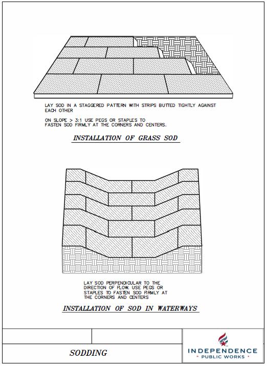
Rough grade area and remove all debris larger than 1 inch in diameter and concentrated areas of smaller debris. Soil preparation of area to be sodded shall be determined by tests to determine lime and fertilizer requirements. Level and roll soil lightly to provide an even grade and firm the surface. Soil should not be excessively wet or dry. Lay first row of sod perpendicular to the slope or direction of flow. Butt subsequent rows tight against previous rows with strips staggered in brick-like pattern. Fill minor gaps with good soil and roll entire surface to ensure contact. Stake, staple and/or net corners and centers of sod strips as required, especially areas of concentrated flow. Water immediately after installation, enough to soak 4 inches into the soil without causing runoff.
OPERATION AND MAINTENANCE PROCEDURES:
Water sod daily for 3 weeks, enough to soak 4 inches into the soil without causing runoff. Reposition areas of sod that have moved along the slope. Remove sediment accumulations, replace sod if necessary. Repair any eroded areas, replace sod, and stabilize as needed. Do not mow until 3 inches of new growth occur. During the first 4 months, mow no more than 1/3 the grass height.
SITE CONDITIONS FOR REMOVAL:
Typically left in place to grow.
Revised July 2019 14
Revised July 2019 15
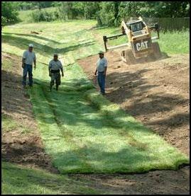
TYPICAL DETAILS:
Installation of sod in a grass-lined channel
Revised July 2019 16
CATEGORY: Erosion Control
USE GROUP: Pre or Post-Construction
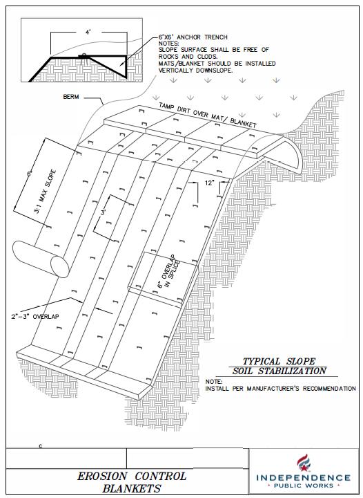
EROSION CONTROL BLANKETS
DEFINITION AND PURPOSE:
An erosion control blanket is a preformed protective blanket of plastic fibers, straw or other plant residue designed to protect soil from the impact of precipitation and overland flow, and retain moisture to facilitate establishment of vegetation. Erosion control blankets are sometimes referred to as Rolled Erosion Control Products (RECPs).
APPROPRIATE APPLICATIONS:
Typically installed on seeded areas for temporary use, and in landscaped areas for permanent use.
CONDITIONS FOR EFFECTIVE USE:
Several factors, such as soil conditions, steepness and length of slope, depth of flow, runoff velocities, and time required to establish desired vegetation influence the choice of product.
Manufacturer’s recommendations must be followed. Products are available for a variety of uses: Netting-synthetic or natural fiber mesh installed over disturbed areas to hold organic mulch and/or seed in place, biodegradable erosion control blanket-natural fiber blanket held together by netting to provide temporary erosion protection on slopes and channels, and permanent erosion control blanket-synthetic blanket material which provides permanent erosion control on slopes and channels with increased water flow velocities.
WHEN BMP IS TO BE INSTALLED:
Dependent upon intended use; immediately after completion of a phase of grading or installation of vegetation.
STANDARDS AND SPECIFICATIONS:
Follow manufacturer’s recommendations and specifications, particularly noting requirements for check slots, fastening devices (staples), and need for firm contact with soil.
OPERATION AND MAINTENANCE PROCEDURES:
Inspection frequency should be in accordance with storm water management plan until adequate vegetation is established. Repair erosion and/or undermining at top of slope. Repair undermining beneath blankets- pull back the blanket(s), fill compact eroded area, revegetate and then firmly secure the blanket(s). Reposition or replace blanket(s) that have moved along the slope or have been damaged.
SITE CONDITIONS FOR REMOVAL:
Temporary blankets will generally degrade naturally; permanent blankets remain in place.
Revised July 2019 17
Revised July 2019 18
CATEGORY: Erosion Control
USE GROUP: Post-Construction
TURF REINFORCEMENT MAT
DEFINITION AND PURPOSE:
A turf reinforcement mat (TRM) is a 3-dimensional permanent synthetic mat that provides a matrix to greatly reinforce the root system of the desired vegetation for permanent erosion protection in high flow channels and on critical slopes. May provide erosion protection equivalent to stone or concrete liners.
APPROPRIATE APPLICATIONS:
Typically installed on seeded areas for permanent use. May be used on steep slopes or grasslined channels with increased water flow velocities and increased shear stress.
CONDITIONS FOR EFFECTIVE USE:
Several factors, such as soil conditions, steepness and length of slope, depth of flow, runoff velocities, and time required to establish desired vegetation, influence the choice of product. Manufacturer’s recommendations must be followed.
WHEN BMP IS TO BE INSTALLED:
Dependent on intended use immediately after completion of a phase of grading, or seeding of vegetation
STANDARDS AND SPECIFICATIONS:
Follow manufacturer’s recommendations and specifications, particularly noting requirements for check slots, edge entrenchment, fastening devices (staples), and the need for firm contact with the soil.
OPERATION AND MAINTENANCE PROCEDURES:
Inspection frequency should be in accordance with storm water management plan of a rainfall event which causes storm water runoff to occur on-site until adequate vegetation is established. Repair erosion and/or undermining at the top of the slope. Repair undermining beneath mats pull back the mat(s), fill and compact eroded area, revegetate and then secure mat(s) firmly. Reposition or replace mats that have moved along the slope or channel and secure firmly. Replace damaged mats.
Revised July 2019 19
SITE CONDITIONS FOR REMOVAL:
Typically turf reinforcement mats are permanently left in place.
TYPICAL DETAILS:
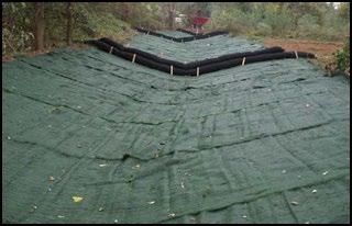
TRMs being used as a channel lining. Checks dams are in place until vegetation is established
Revised July 2019 20
\
CATEGORY: Erosion Control
USE GROUP: Post-Construction
STREAMBANK STABILIZATION
DEFINITION AND PURPOSE:
A vegetative, structural, or combination treatment of streams designed to stabilize the stream and reduce erosion. It is important to note that a systemic analysis of the entire reach of stream must be conducted in order to avoid unintended negative impacts on a stream as a result of a corrective action at an isolated location. A wide array of products and methodologies can be used to stabilize streams: live stakes, cellular confinement matrices, articulated block pavers, riprap, gabion baskets, turf reinforcement mats, revetments, large woody debris, grade controlling structures, stilling basins, etc.
APPROPRIATE APPLICATIONS:
All construction projects that disturb or occur within stream channels and their associated riparian areas.
CONDITIONS FOR EFFECTIVE USE:
Acceptable methods vary widely due to the unique nature of each reach of channel. Design considerations include: current and future watershed conditions, discharge, velocity, sediment load, channel slope, control of bottom scour (incising), soil conditions, compatibility with other improvements, changes in channel alignment, and protection and maintenance of fish and wildlife habitats and existing tree canopy. U.S. Army Corps of Engineers permits may be applicable.
WHEN BMP IS TO BE INSTALLED:
After streambank(s) have been disturbed.
STANDARDS AND SPECIFICATIONS:
Procedures are specific to materials used. Generally, stabilize the channel bottom first to prevent incising and kick points from undermining the bank protection. Start and stop bank protection at stable points along the channel. Minimize the size of all disturbed areas and stabilize as soon as each phase of construction is complete. Use other BMPs to prevent runoff from disturbing the streambank protection area until it has been completed. Store all construction materials well away from the stream. At the end of each workday, move all construction equipment out of and away from the stream to prevent flooding. Avoid steep slopes on the streambank. Standards & Specifications specific to the site and application must be developed signed, and sealed by a professional engineer licensed in the state of Missouri.
Revised July 2019 21
OPERATION AND MAINTENANCE PROCEDURES:
During construction, Inspection frequency should be in accordance with storm water management plan Repair, relocate, or add BMPs protecting channel until the streambank protection is operational. Remove sediment as needed.
SITE CONDITIONS FOR REMOVAL:
TYPICAL DETAILS:
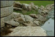
Multiple methods and products, including a retaining wall, large boulders, vegetation, and turf reinforcement mats, being used for a streambank stabilization project.
Revised July 2019 22
RUNOFF MANAGEMENT
Revised July 2019 23
CATEGORY: Runoff Management
USE GROUP: Pre-Construction
CHECK DAMS
DEFINITION AND PURPOSE:
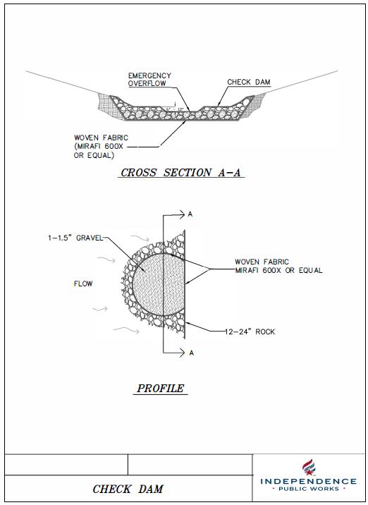
Check dams reduce scour and channel erosion by reducing flow velocity and encouraging sediment settlement. A check dam is a small device constructed of rock, gravel bags, sandbags, fiber rolls, or other proprietary product placed across a natural or man-made channel or drainage ditch. Not to be constructed from straw bales or silt fence.
APPROPRIATE APPLICATIONS:
Check dams can be placed at intervals along drainage swales or channels. The top of the downstream check dam should be level with the base of the upstream check dam. Check dams can also be used during the establishment of grass linings in drainage ditches or channels or in temporary ditches where the short length of service does not warrant establishment of erosion-resistant linings.
CONDITIONS FOR EFFECTIVE USE:
Type of Flow: Moderate concentrated flow.
Contributing Area: Maximum of 10 acres. Not to be used in perennial streams.
WHEN BMP IS TO BE INSTALLED:
Triangulated silt dikes used as check dams. Before disturbing vegetation in contributing drainage area; right after construction of drainage way.
STANDARDS AND SPECIFICATIONS:
Check dams should be placed at a distance and height to allow small pools to form behind them. Install the first check dam approximately 5 meters (16 feet) from the outfall device and at regular intervals based on slope gradient and soil type based upon manufacturer’s specifications. For multiple check dam installation, backwater from the downstream check dam should reach the toe of the upstream dam. High flows (typically a 2-year storm or larger) should safely flow over the check dam without an increase in upstream flooding.
Revised July 2019 24
OPERATION AND MAINTENANCE PROCEDURES:
Inspection frequency should be in accordance with storm water management plan. Remove trash and leaf accumulation. Remove sediment when depth reaches one-half of the check dam height. Repair/restore dam structure, if necessary, to original configuration to protect the banks.
SITE CONDITIONS FOR REMOVAL:
Remove after contributing areas have been adequately stabilized and vegetation is adequately established in drainage way Regrade and vegetate area of check dam.
TYPICAL DETAILS:
Revised July 2019 25
Revised July 2019 26
CATEGORY: Runoff Management
USE GROUP: Pre or Post-Construction
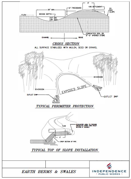
EARTH BERMS AND DRAINAGE SWALES
DEFINITION AND PURPOSE:
A compacted earth or gravel ridge, excavated channel, or a combination of ridge and channel designed to direct runoff away from or around disturbed areas. Diversions built on a level contour are used in combination with temporary slope drains to provide adequate conveyance. Diversions built with positive drainage slopes release runoff into additional BMPs, such as sediment traps or level spreaders.
APPROPRIATE APPLICATIONS:
These features may be used to: convey surface runoff down sloping land, intercept and divert runoff to avoid sheet flow over sloped surfaces, divert and direct runoff towards a stabilized watercourse, drainage pipe or channel, and intercept runoff from paved surfaces. Berms, swales, and lined ditches also may be used: below steep grades where runoff begins to concentrate, along roadways and facility improvements subject to flood drainage, at the top of slopes to divert run-on from adjacent or undisturbed slopes. Also, at bottom and mid-slope locations to intercept sheet flow and convey concentrated flows.
CONDITIONS FOR EFFECTIVE USE:
Type of Flow: Sheet flow and low-volume concentrated flows.
Contributing Area: Contributing slope length-300 feet maximum.
WHEN BMP IS TO BE INSTALLED:
Prior to disturbance of natural vegetation on slopes and at intervals during construction of fill slopes.
STANDARDS AND SPECIFICATIONS:
Care must be applied to correctly size and locate berms, swales, and ditches. Excessively steep, unlined berms and swales are subject to gully erosion. Grade and compact channel and/or ridge. Conveyances should be stabilized with vegetation or a protective lining. Provide stabilized outfall areas. Other BMPs, such as check dams and erosion control blankets, may be necessary to prevent scour and erosion.
OPERATION AND MAINTENANCE PROCEDURES:
Inspection frequency should be in accordance with storm water management plan. Inspect channel linings, embankments, and beds of ditches and berms for erosion and accumulation of debris and sediment. Remove debris and sediment, repair linings and embankments as needed-replace riprap, linings or soil stabilizers in accordance with submitted approved plan.
Revised July 2019 27
SITE CONDITIONS FOR REMOVAL:
Temporary diversions should be removed as soon as the surrounding drainage area has been stabilized.
TYPICAL DETAILS:
Revised July 2019 28
Revised July 2019 29
CATEGORY: Runoff Management
USE GROUP: Pre-Construction
WATER DIVERSIONS
DEFINITION AND PURPOSE:
Water diversions consist of a system of structures and measures that intercept clear surface water runoff upstream of a project site, transport it around the work area, and discharge it downstream with minimal water quality degradation for either the project construction operations or the construction of the diversion.
APPROPRIATE APPLICATIONS:
A water diversion is typically implemented where appropriate permits have been secured and work must be performed in a live stream or water body. Water diversions are appropriate for isolating construction activities occurring within or near a water body such as streambank stabilization, or culvert, bridge, pier or abutment installation. They also may be used in combination with other methods, such as water bypasses and/or pumps. Pumped diversions are suitable for intermittent and low flow streams. Excavation of a temporary bypass channel or passing the flow through a pipe is appropriate for the diversion of streams less than 20 feet wide, with flow rates less than 99 cubic feet/second.
CONDITIONS FOR EFFECTIVE USE:
Type of Flow: Concentrated flow.
Capacity of Device: Sized for 2 year rainfall intensity event.
WHEN BMP IS TO BE INSTALLED:
Prior to work begins done in or adjacent to a water body.
STANDARDS AND SPECIFICATIONS:
Site conditions will dictate the design. Generally, excavate Pumped stream diversion for bridge installation. Diversion area except for area of upstream connection. Install pipe bedding or channel lining as required. Install pipe and backfill to required dimensions. Install additional BMPs as designed-both in the diversion and downstream. Make the final connection to upstream storm sewer system. Must be designed, signed and sealed by a professional engineer licensed in the state of Missouri
Revised July 2019 30
OPERATION AND MAINTENANCE PROCEDURES:
Inspection frequency should be in accordance as approved and agreed upon by the city and any applicable permitting authorities. Remove debris and sediment. Repair eroded areas and stabilizes-a wider channel, bigger pipe, or additional stabilization may need to be designed.

SITE CONDITIONS FOR REMOVAL:
Remove the water diversion when work in or adjacent to the water body has ceased.
TYPICAL DETAILS:
Revised July 2019 31
Pumped stream diversion for bridge installation

Revised July 2019 32

Revised July 2019 33
CATEGORY: Runoff Management
USE GROUP: Pre-Construction
SLOPE DRAINS
DEFINITION AND PURPOSE:
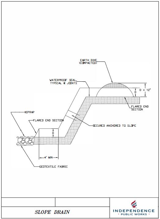
A slope drain is a flexible or rigid pipe or lined channel/swale which extends from the top to the bottom of a cut or fill slope. These structures are designed to protect exposed slopes from upstream runoff and can be used with other BMPs to intercept and direct surface flow away from disturbed slope areas. Slope drains typically extend beyond the toe of the slope to a stable area or outlet.
APPROPRIATE APPLICATIONS:
Slope drains may be used on construction sites where slopes may be eroded by surface runoff.
CONDITIONS FOR EFFECTIVE USE:
Type of Flow: Sheet flow and concentrated flow.
Contributing Area: Maximum of 5 acres per slope drain; pipe sized for 2 year rainfall intensity event.
WHEN BMP IS TO BE INSTALLED:
Concurrently with diversion devices as soon as cut and fill operations have occurred.
STANDARDS AND SPECIFICATIONS:
Slope drains must be installed and maintained properly because failure is likely to result in severe erosion of the slope. Other points of concern are failure from overtopping due to inadequate pipe inlet capacity or blockage, and lack of maintenance of the upstream diversion device capacity. Generally install slope drain down the slope-perpendicular to slope contours, extending beyond the toe of slope. Install flared end or t-section at pipe inlet. Section should be well entrenched and stable so water can enter freely. Compact fill over and around pipe in area of diversion device. Ensure that all pipe connections are secure and watertight. Securely anchor the exposed section of the drain with stakes. Install flared end section at pipe outlet-discharge into a sediment trap or other stabilized outlet. Protect area around inlet with filter fabric. Protect outlet with riprap or other energy dissipation device.
OPERATION AND MAINTENANCE PROCEDURES:
Inspection frequency should be in accordance with storm water management plan Remove sediment and trash accumulation at inlet. Repair settlement, cracking, or piping holes. Repair
Revised July 2019 34
leaks or inadequate anchoring along pipe. Remove sediment and stabilize eroded areas at outletextend if necessary.
SITE CONDITIONS FOR REMOVAL:
Remove concurrently with upstream diversion device after slope has been stabilized. Stabilize the exposed areas where the slope drain and diversion device were removed.
TYPICAL DETAILS:
Revised July 2019 35
Revised July 2019 36
CATEGORY: Runoff Management
USE GROUP: Pre-Construction
DEWATERING OPERATIONS
DEFINITION AND PURPOSE:
Dewatering operations are practices, such as dewatering bags, filter socks, and pump trucks that manage the discharge of pollutants when non-storm water and accumulated precipitation must be removed from a work location so that construction work may be accomplished. Water cannot be directly pumped into the City’s storm sewer system, sanitary sewer system, streams, or lakes.
APPROPRIATE APPLICATIONS:
These practices are implemented for removing standing storm water and non-storm water from construction sites. Non-storm waters include, but are not limited to, groundwater, water from cofferdams, water diversions, and waters used during construction activities that must be removed from a work area. Practices identified in this section are also appropriate for implementation when managing the removal of accumulated precipitation (storm water) from depressed areas at a construction site.
CONDITIONS FOR EFFECTIVE USE:
Type of Flow: Standing water.
WHEN BMP IS TO BE INSTALLED:
Prior to work beginning in or adjacent to standing water.
STANDARDS AND SPECIFICATIONS:
Site conditions will dictate the design. A dewatering plan should be submitted as part of the SWPPP detailing the location of dewatering activities, equipment, and discharge point. Additional permits or permissions from other agencies may be required for some dewatering operations. Sediment control and other appropriate BMPs (e.g. outlet protection/energy dissipation, sediment trap, weir tank, gravity bag filter, sand media particulate filter, pressurized bag filter, etc.) need to be employed when water is discharged. Dewatering discharges must not cause erosion at the discharge point.
Revised July 2019 37
OPERATION AND MAINTENANCE PROCEDURES:
Inspect all BMPs associated with the dewatering, repair or replace to ensure the BMPs function as designed. Accumulated sediment removed during the maintenance of a dewatering device can be incorporated into the site. Accumulated sediment that is co-mingled with other pollutants must be disposed of in accordance with all applicable laws and regulations.
SITE CONDITIONS FOR REMOVAL:
Remove the dewatering operation when work in or adjacent to the standing water has ceased.
TYPICAL DETAILS:
Revised July 2019 38

Revised July 2019 39
SEDIMENT CONTROL
Revised July 2019 40
CATEGORY: Sediment Control
USE GROUP: Post-Construction
VEGETATED FILTER STRIP
DEFINITION AND PURPOSE:
Vegetated buffers are areas of natural or established vegetation maintained to protect the water quality of neighboring areas. Buffer zones slow storm water runoff, provide an area where runoff can permeate the soil, contribute to ground water recharge, and filter sediment. Slowing runoff also helps to prevent soil erosion and streambank collapse.
APPROPRIATE APPLICATIONS:
Vegetated buffers can be used in any area able to support vegetation. They are most effective and beneficial on floodplains, near wetlands, along streambanks, and on unstable slopes. Filter strips can be used adjacent to low or medium density residential areas on gently sloping ground.
CONDITIONS FOR EFFECTIVE USE:
Type of Flow: Overland sheet flow only-cannot treat high velocity flows.
WHEN BMP IS TO BE INSTALLED:
Immediately after rough grading to trap sediment during construction and/or immediately after final grading as a permanent measure to control surface runoff.
STANDARDS AND SPECIFICATIONS:
Determine buffer widths after carefully considering slope, vegetation, soils, depth to impermeable layers, runoff sediment characteristics, type and amount of pollutants, and annual rainfall. Make sure buffer widths increase as slope increases. In areas where flows are more concentrated and fast, combine buffer zones with other practices such as level spreaders, infiltration areas, or diversions to prevent erosion and riling. Fence off any undisturbed vegetated strips to be preserved. No activity, including parking/storing vehicles or equipment, shall be permitted in the vegetated/woody strip. If a grass filter strip is constructed, it must be completed and vegetated before construction in a contributing area is started.
OPERATION AND MAINTENANCE PROCEDURES:
Inspection frequency should be in accordance with storm water management plan
Remove sediment accumulation as it becomes noticeable. Fill and compact eroded areas and reseed, mulch and fertilize or establish other vegetation in the affected areas. After improvements are complete, regrade and reseed the top edge of the filter strip to remove sediment trapped during construction and prolong the effective use of the filter strip.
Revised July 2019 41
SITE CONDITIONS FOR REMOVAL: Not Applicable
TYPICAL DETAILS:

Revised July 2019 42
CATEGORY: Sediment Control
USE GROUP: Pre-Construction
SILT FENCE
DEFINITION AND PURPOSE:
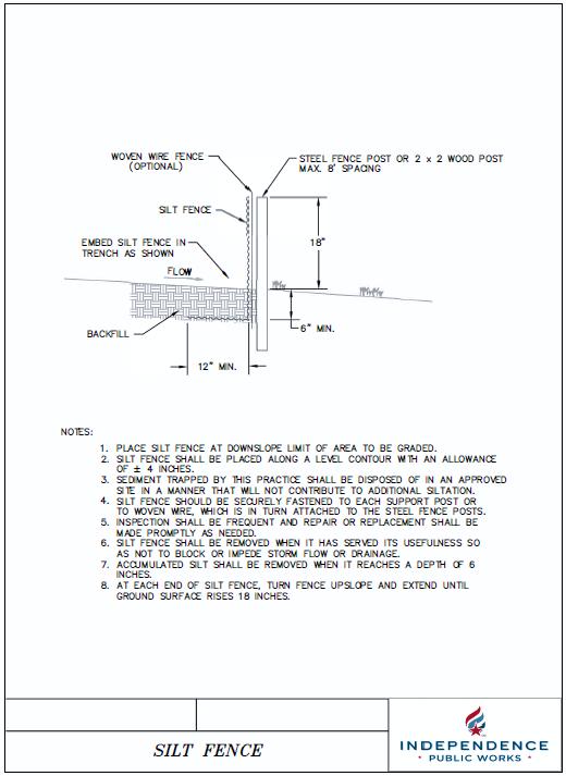
A silt fence consists of a length of filter fabric stretched between anchoring posts spaced at regular intervals along the site at low/downslope areas. The filter fabric should be entrenched in the ground between the support posts. When installed correctly and inspected frequently, silt fences encourage the ponding of runoff and settling of sediment.
APPROPRIATE APPLICATIONS:
Installed along slopes, at bases of slopes, and around the perimeter of a site as a final barrier to sediment being carried off site. Silt fence should not be used in areas of concentrated flow or as check dams.
CONDITIONS FOR EFFECTIVE USE:
Type of Flow: Sheet flow only
Contributing Area: Drainage area should not exceed 0.25 acres per 100-foot fence length. Silt fence should not be placed perpendicular to a slope.
WHEN BMP IS TO BE INSTALLED:
Prior to disturbance of natural vegetation and at intervals during construction of fill slopes.
STANDARDS AND SPECIFICATIONS:
If a standard-strength fabric is used, it can be reinforced with wire mesh behind the filter fabric. This increases the effective life of the fence. The maximum life expectancy for synthetic fabric silt fences is about 6 months, depending on the amount of rainfall and runoff. The fence should be designed to withstand the runoff from a 10- year peak storm event. Generally, drive posts for fence line, dig trench to required dimensions in front of posts for fabric burial, attach wire mesh to posts (if necessary), attach fabric to posts-allowing required length below ground level to run fabric along bottom of trench, and backfill and compact soil in trench to protect and anchor fabric. Alternate construction procedures include installing the fence by slicing it into the ground with specialized equipment in accordance with manufacturer specifications.
Revised July 2019 43
OPERATION AND MAINTENANCE PROCEDURES:
Inspection frequency should be in accordance with storm water management plan. Remove sediment buildup once it accumulates to 6 inches. Replace torn/clogged fabric; repair loose fabric. Repair unstable or broken posts. Stabilize any areas susceptible to undermining. Add additional fencing if necessary to provide adequate protection.
SITE CONDITIONS FOR REMOVAL:
After permanent vegetation of slope is established. Remove fence, regrade trench area, and vegetate.
TYPICAL DETAILS:

Revised July 2019 44
Silt fence used as a perimeter control.
Revised July 2019 45
CATEGORY: Sediment Control
USE GROUP: Pre or Post-Construction
COMPOST FILTER BERMS
DEFINITION AND PURPOSE:
A compost filter berm, trapezoidal in cross section, is a dike of compost or a compost product that is placed perpendicular to sheet flow runoff to control erosion in disturbed areas and retain sediment. It can be used in place of a traditional control tool such as a silt fence or compost filter socks.
APPROPRIATE APPLICATIONS:
Vegetated compost filter berms are generally placed along the perimeter of a site, or at intervals along a slope. A filter berm also can be used as a check dam in low-slope, small drainage ditches.
CONDITIONS FOR EFFECTIVE USE:
Type of Flow: Sheet flow and small concentrated flow.
Contributing Area: Drainage area should not exceed 0.25 acres per 100-foot berm length.
WHEN BMP IS TO BE INSTALLED:
Prior to disturbance of natural vegetation and at intervals during construction of fill slopes.
STANDARDS AND SPECIFICATIONS:
The compost filter berm dimensions should be modified based on site-specific conditions, such as soil characteristics, existing vegetation, site slope, and climate, as well as project-specific requirements. Generally the berms are trapezoidal in cross section with the base twice the height of the berm. The compost should be uniformly applied to the soil surface, compacted, and shaped to into a trapezoid. Compost filter berms can be installed on frozen or rocky ground. The filter berm may be vegetated by hand, by incorporating seed into the compost prior to installation, or by hydraulic seeding following berm construction.
OPERATION AND MAINTENANCE PROCEDURES:
Inspection frequency should be in accordance with storm water management plan
Remove sediment buildup deeper than ½ the filter berm. Any areas that have been washed away should be replaced. If the berm has experienced significant washout, a filter berm alone may not be the appropriate BMP for this area or the size of the berm may need to be increased.
Revised July 2019 46
SITE CONDITIONS FOR REMOVAL:
Vegetated filter berms are normally left in place and provide long-term filtration of storm water as a post-construction best management practice (BMP). If temporary, break down the berm once construction is complete and spread the compost around the site as a soil amendment or mulch.
TYPICAL DETAILS:
Not Applicable
Revised July 2019 47
CATEGORY: Sediment Control
USE GROUP: Pre or Post-Construction
SEDIMENT BASIN
DEFINITION AND PURPOSE:
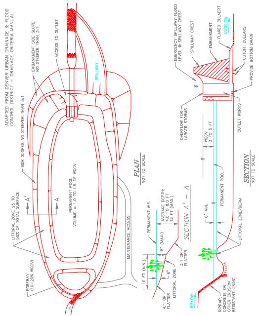
A temporary settling pond designed to slowly release runoff, detaining it long enough to allow most of the sediment to settle out. Basins should be used in conjunction with additional BMPs, such as temporary seeding, velocity dissipaters, perimeter controls, inlet protection, etc., to reduce the total amount of sediment washing into them. Sediment basins may also be designed to be converted to permanent storm water detention basins after construction has ended.
APPROPRIATE APPLICATIONS:
Should be located as close to the sediment source as possible. A sediment basin should not be used in areas of continuously running water (live streams) or areas where failure of the embankment will result in loss of life, damage to homes or structures, or prevent the use of roadways or utilities.
CONDITIONS FOR EFFECTIVE USE:
Type of Flow: Sheet flow and concentrated flow.
Basin Volume: See Storm Water Design Criteria Manual.
WHEN BMP IS TO BE INSTALLED:
Prior to disturbance of natural vegetation.
STANDARDS AND SPECIFICATIONS:
The basin design must be designed ,signed and sealed by professional engineer registered in the state of Missouri. Excavate basin to length, width, depth and slopes specified on plans. Place and compact fill to construct dam to elevation at least 1 foot above crown of outlet pipe. Install outlet pipe and compact clayey soil around pipe. Install the perforated riser pipe, wrap with fabric, and surround with uniformly graded gravel. Install BMP at downstream end of outlet pipe. Grade and stabilize spillway. Install monitoring post near outlet of basin. Mark maximum allowable sediment depth.
OPERATION AND MAINTENANCE PROCEDURES:
Inspection frequency should be in accordance with storm water management plan.
Revised July 2019 48
Remove trash accumulation at outlet. Remove sediment accumulations once sediment reaches design depth as indicated on monitoring posts. Repair and revegetate any erosion damage on spillway. Repair settlement, cracking, piping holes, or seepage at embankment. Replace gravel around riser if basin does not drain properly.
SITE CONDITIONS FOR REMOVAL:
Remove after upstream areas are stabilized. Regrade as appropriate and vegetate immediately in accordance with Best Management Practices identified in this manual.
TYPICAL DETAILS:
Revised July 2019 49
Revised July 2019 50

Revised July 2019 51

Revised July 2019 52
CATEGORY: Sediment Control
USE GROUP: Pre-Construction
INLET PROTECTION-CURB
DEFINITION AND PURPOSE:
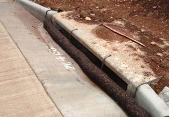
A temporary sediment control barrier consisting of a filter media, such as compost filter socks, gravel and mesh, sandbags, gravel bags, etc., around a curb and gutter inlet designed to prevent sediment from entering the storm sewer. Shallow temporary ponding during and after rainfall should be expected.
APPROPRIATE APPLICATIONS:
At inlets where runoff may contain sediment-laden water.
CONDITIONS FOR EFFECTIVE USE:
Type of Flow: Sheet flow and concentrated flow
Contributing Area: Maximum of 1 acre.
WHEN BMP IS TO BE INSTALLED:
Immediately after installation of the inlet, or prior to land disturbing activities beginning on the contributing upstream area to the inlet.
STANDARDS AND SPECIFICATIONS:
Typical types of curb and gutter inlet protection include: fabricated inlet filters (follow manufacturer’s instructions), compost filter sock (make sure that both ends of the sock are anchored accordingly), gravel and wire mesh (construct and anchor wood frame, fasten wire mesh and fabric to frame, and place the gravel on top of the entire structure), and sandbags and gravel bags (may be placed either as a j-hook on the upstream end of the inlet or as a full barrier, sometimes stacked 2 bags high, across the entire opening of the inlet). Incorporate an overflow bypass into the inlet protection structure in areas, such as heavy traffic streets, where excessive ponding of water around the inlet may become a safety issue.
OPERATION AND MAINTENANCE PROCEDURES:
Inspect inlet protection of all media types as needed, or as necessary, to make sure they are functioning properly. Remove trash and debris. Remove sediment from the inlet protection when half of the protection structure height has been filled. Repair elements to original configuration as needed.
Revised July 2019 53
SITE CONDITIONS FOR REMOVAL:
Remove after contributing drainage areas have been adequately stabilized.
TYPICAL DETAILS:
Compost fiber sock used as a curb and gutter inlet protection.
Revised July 2019 54

Revised July 2019 55
CATEGORY: Sediment Control
USE GROUP: Pre-Construction
STREET SWEEPING AND VACUUMING
DEFINITION AND PURPOSE:
Practices used to remove tracked sediment to prevent the sediment from entering a storm drain or watercourse.
APPROPRIATE APPLICATIONS:
These practices are implemented anywhere sediment is tracked from the project site onto public or private paved roads, typically at points of ingress/egress.
CONDITIONS FOR EFFECTIVE USE:
Sweeping and vacuuming may not be effective when soil is wet or muddy.
WHEN BMP IS TO BE INSTALLED:
Anytime sediment/silt has been tracked from the site onto public or private paved surfaces.
STANDARDS AND SPECIFICATIONS:
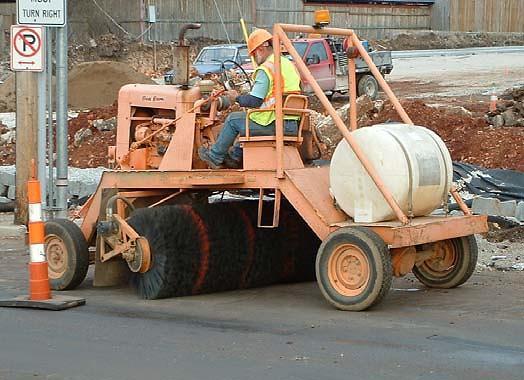
Visible sediment tracking should be swept and/or vacuumed daily. Adjust brooms frequently to maximize efficiency of sweeping operations. Be careful not to sweep up any unknown substance or any object that may be potentially hazardous. If not mixed with debris or trash, consider incorporating the removed sediment back into the project. After sweeping is finished, properly dispose of sweeper wastes at an approved dumpsite. Do not wash any sediment or debris down the storm drain!
OPERATION AND MAINTENANCE PROCEDURES:
Inspect ingress/egress access points, and sweep tracked sediment as needed, or as required.
SITE CONDITIONS FOR REMOVAL:
Not Applicable
Revised July 2019 56
TYPICAL DETAILS:
Remember dirt/sediment tracked onto streets is the #1 complaint of construction sites. Be vigilant about cleaning up mud on streets and sidewalks.
Revised July 2019 57
CATEGORY: Tracking Control
USE GROUP: Pre-Construction
CONSTRUCTION EXIT
DEFINITION AND PURPOSE:
A stabilized entrance to a construction site is designed to minimize the amount of sediment tracked from the site on vehicles and equipment. Mud and sediment fall off of tires as they bounce along the stabilized entrance. Additional measures in the form of a wash down area could also be included on site
.
APPROPRIATE APPLICATIONS:
At locations where it is safe for construction vehicles and equipment to access existing streetspreferably at location of future streets or drives.
CONDITIONS FOR EFFECTIVE USE:
Site conditions will dictate design and need. Ditches or pipes, if needed, sized for 2 year rainfall intensity event; HGL 6” below surface of entrance.
WHEN BMP IS TO BE INSTALLED:
One of the first things done, prior to vehicles or equipment accessing unpaved areas.
STANDARDS AND SPECIFICATIONS:
Limit the points of entrance/exit to the construction site. Properly grade and compact each construction entrance/exit to prevent runoff from leaving the site. Install culvert under entrance if needed to maintain positive drainage. Place fabric and cover with aggregate (minimum of 3”-6” shot rock), forming a diversion across the entrance, if needed, to direct runoff away from the roadway. Require all employees, subcontractors, and suppliers to utilize the stabilized construction access.
Revised July 2019 58
OPERATION AND MAINTENANCE PROCEDURES:
Inspection frequency should be in accordance with storm water management plan, for damage and assess effectiveness of the BMP. Remove sediment and clods of dirt from construction entrance continuously. Replace rock, if necessary, to maintain a clean surface. Repair any areas that have settled. Keep all temporary roadway ditches clear. Immediately remove any mud or debris tracked onto paved surfaces.
SITE CONDITIONS FOR REMOVAL: Remove when vehicles and equipment will no longer access unpaved areas.
TYPICAL DETAILS:
Revised July 2019 59

Revised July 2019 60
CATEGORY: Pollution Prevention
USE GROUP: Pre-Construction
NON-SEDIMENT POLLUTION CONTROL (HOUSEKEEPING)
DEFINITION AND PURPOSE:
Control measures designed to prohibit chemicals, hazardous materials, solid waste, human waste and construction debris from polluting storm water. Pollutants carried in solution or as surface films on runoff will be carried through most erosion control and sediment capture BMPs. Keeping substances like fuel, oil, asphalt, paint, solvents, fertilizer, soil additives, concrete wash water, solid waste, human waste and construction debris from polluting runoff can be accomplished to a large extent through good housekeeping on the site and following the manufacturer’s recommendations for disposal.
APPROPRIATE APPLICATIONS:
Temporary sanitary facilities (do not place on top of storm inlets or near waterways), collection, storage and fueling areas should be located onsite in an area that does not receive a substantial amount of runoff from upland areas and does not drain directly to lakes, creeks, streams, rivers, sewers, groundwater, wetlands, or road ditches.
CONDITIONS FOR EFFECTIVE USE:
An effective management system requires training and signage to promote proper storage, handling and disposal of materials, and follow up observations of actions and inspection of storage areas by management. Plans should contain notes clearly stating requirements for addressing potential pollutants.
WHEN BMP IS TO BE INSTALLED:
Immediately following installation of construction entrance.
STANDARDS AND SPECIFICATIONS:
Place waste receptacles (empty on a regular basis) near area of work. All fueling facilities present on the site shall adhere to applicable federal and state regulations concerning underground storage, above ground storage, and dispensers. Hazardous wastes shall be managed according to Missouri Hazardous Waste Laws and Regulations. Install appropriate signage. Post guidelines for proper handling, storage and disposal of materials, and emergency spill cleanup on site. Provide sufficient temporary toilet facilities to serve the number of workers on the site.
Revised July 2019 61
OPERATION AND MAINTENANCE PROCEDURES:
Inspect activities, storage areas, and control devices as needed, Inspection frequency should be in accordance with storm water management plan. Maintenance of temporary toilet facilities should be frequent and thorough. Make necessary corrections and repairs.
SITE CONDITIONS FOR REMOVAL:
Remove after contributing drainage areas have been adequately stabilized.
TYPICAL DETAILS:
Not Applicable
Revised July 2019 62


