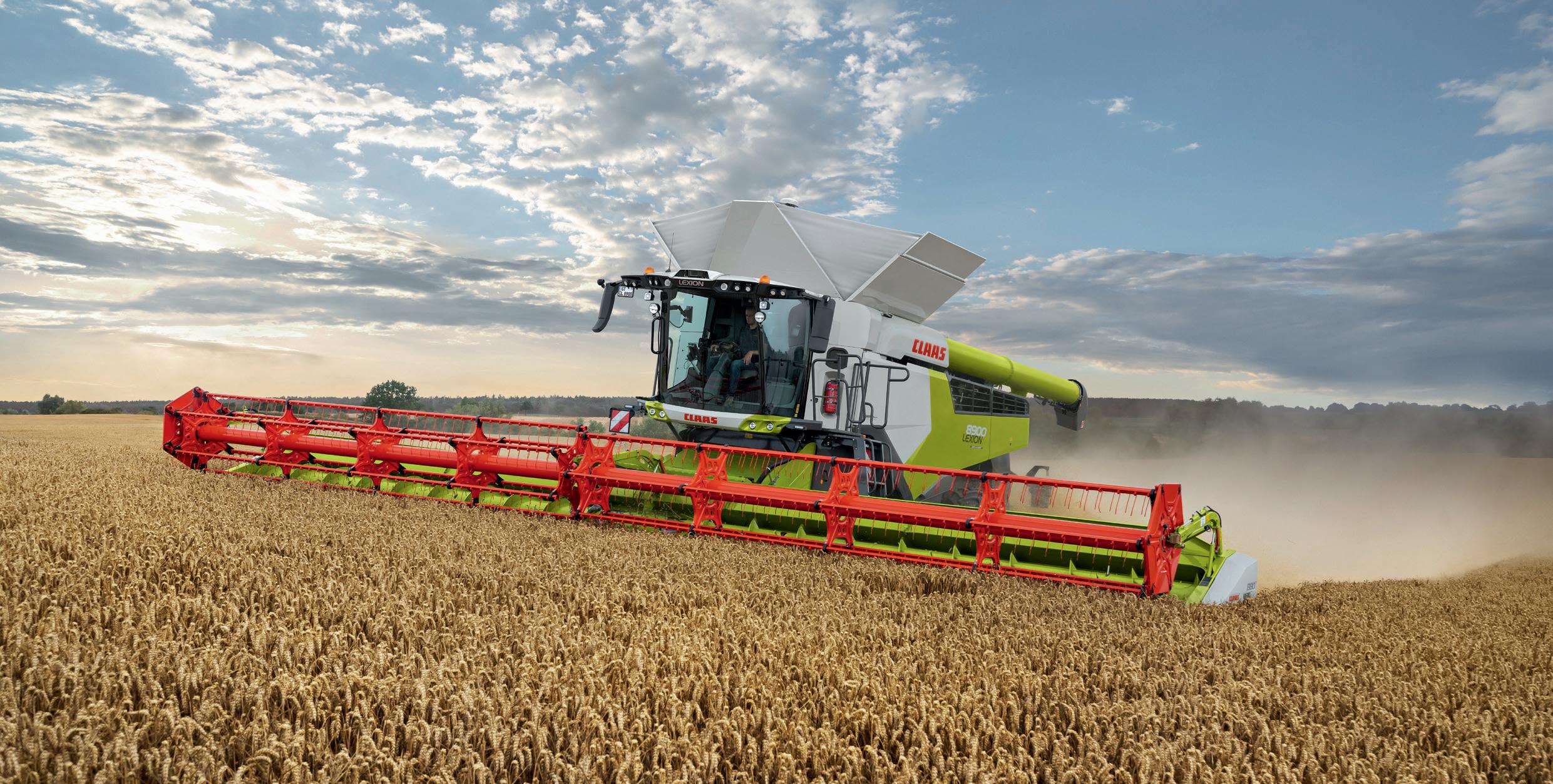



This guide has been produced as a reference to operator’s training. The aim is to aid operator’s with familiarisation and settings of CLAAS LEXION combine harvester. This guide does not replace the operator’s manual. More in depth information is available within the operator’s manual.
Your CLAAS combine is designed for output and efficiency but this can only be achieved with the correct operation and maintenance of the machine.
Make sure you are familiar with the operator’s manual before using the machine. The operator’s manual is an integral part of the machine. It addresses the user and contains safety relevant information. Only procedures specified in the operator’s manual are safe.
Read and observe the operator’s manual before starting work.
If you need help understanding the content, contact your local CLAAS Dealer.




* Different displays can be selected in user defined displays.

* Can be changed in user defined display.


5 Use the slider (or)


6
7 Double tap the dial


When carrying out any service operation, make sure that the correct procedures are followed. See operator’s manual chapter 9.1 for the complete service requirements. In CEBIS, there is also a quick guide on the service requirements.
Grease the appropriate grease points as per the operator’s manual - it is recommended to grease the rotor bearings every day. Ensure that the whole machine is blown down daily.
WARNING!


End to End Guides
Centre to Centre Guides
Do not unscrew the nuts from the threaded spindle.
Slacken off nuts (2) and (3).
Twist nut (3) until the ends of gauge rods (4) are positioned in front of one another without play.
Lock nuts (2) and (3) together.
Components are tensioned due to the force of a relieving spring, incorrect removal may result in injury.

Gauge Rod Type
Check if tube (4) makes contact at position (B) without pressure. Slacken off nuts (5). Turn nuts (5) until tube (4) makes contact at position (B) without pressure. Lock the nuts (5).


Slacken
Turn out spring guide tube (2) by 3 revolutions. Turn nut (4) until spacer sleeve (3) makes contact at position (A) without pressure.
Jam nut (4) and cylinder barrel (2).
Check if jockey pulley (1) can be rotated by hand and makes contact with belt (R48). If necessary, adjust dimension (X) of spring (2). Remove nut (3). Relocate bolt (4) to another hole.
4.

When checking the level make sure the correct pre condition are followed see Operator manual, 9 Maintenance, 9.8 Hydraulic system, checking the hydraulic oil tank level. The correct hydraulic oil level is between the maximum mark (A) and the minimum mark (B).
Let the diesel engine and the coolant cool down. The expansion tank is sufficiently filled when the cooling liquid reaches up to the bottom edge of the filler neck. Sight glass (2) on the expansion tank is now completely filled.

Daily zeroing
This should be carried out with the machine running, threshing engaged at maximum speed and with no material in the machine.

The following items need to be zeroed on a daily basis:

1. Set “zero returns”


2. Set “zero yield”
Learn the AUTOCONTOUR end stops at the start of the season.


Select the calibration
At the start of each crop, make sure you have selected the correct crop type, or your personal crop settings.


Select crop type and then press

Tips: Learn the working position of the cutterbar in the front attachment menu.
This may also have to be changed when combining different crops.
The working position will have to be re-learnt if the cutterbar is changed.
The cutterbar is one of the most important parts of the combine harvester. It is designed to cut and gather the crop from the field.
Dividers
The first part of the cutterbar to make contact with the crop are the dividers. There are two types, a standard and a long divider.
Lifters
It is recommended that lifters should be fitted to CLAAS cutterbars. The lifters should be fitted by placing the first one on the fifth finger from the RHS of the cutterbar and then on every fourth one thereafter.
Tips:
To aid crop feed into the cutterbar table, the table length can be adjusted towards and away from the cutterbar auger.
Make sure that the height of the divider is set so it does not run on the ground.
Set the height the same as the stubble.
Check the lifters everyday, if they are loose or bent remove and replace them.


Tips: Remove any knife play by adjusting the keeps and make sure that the fingers are not rounded or bent. A clearer cutting knife will reduce stress on the knife drive.
If an issue occurs with crop wrapping around the table auger in difficult conditions, there are a number of procedures that can be carried out (try one thing at a time).
One way is to adjust the stripper plates behind the auger. There is also a second scraper under the auger that can be accessed over the top of the auger.


retractable fingers across the length of the auger - leaving just the middle
Lift the skids as high as possible to get as much movement for the sensor cutterbar should be set to suit the


Check that the knife is in good condition in order for it to work effectively. This involves replacing damaged or broken sections.
It is recommended that lifters should be fitted to CLAAS cutterbars except the CONVIO FLEX. Fitting the lifters will help lift the crop onto the table.
The lifters should be fitted by placing the first one on the fifth finger from the RHS of the cutterbar and then on every fourth one thereafter.


Auger Finger Position
Long crop = Lower hole (A)
Short crop = Upper hole (D)
Drilled holes (E) and
(F) cannot be used.
Unscrew bolt (1)
Slacken off bolt (2)
Adjust the fingers using the lever (3)


De-awning can be carried out by operating the lever on the right hand side of the machine, which in turn closes or opens a set of plates under the APS concave. This keeps the crop in the threshing system until the main concave.
The concave flap can be engaged and disengaged from the CEBIS screen or by the handle on the left of the machine. This adjustment can be made if increased threshing is required.
The concave bar creates a larger friction area in the threshing system. The bar can be used to aid threshing in hard crop varieties. Find more detailed information on chapter 7.14.
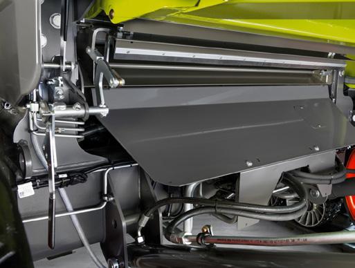
The stone trap is situated between the front elevator and the APS concave. It is important that the stone trap is emptied regularly to allow for foreign objects to be expelled before they enter the drum. Ensure the lever is in the up and locked position before lowering the feeder housing.
Only engage the concave flap, threshing bar and the disawning plates one at a time.

To obtain initial settings, it is recommended that the ‘CLAAS settings’ are loaded through CEBIS. The operator can use these settings as a starting point so adjustments can be made.
The prime objective here is to remove the maximum amount of grain with minimum damage to grain and straw. Over-threshing can crack grains, produce more chaff and use more power.
It is imperative for the performance of the machine that the concaves are kept clean. Generally, wider concave gaps are accepted when using a LEXION.
Tips: Only make one adjustment at a time.
Only do just enough threshingover threshing causes overloading of the sieves and uses power unnecessarily.
It is recommended that the drum speed is adjusted by 50rpm at a time.
The rotor cover plates can be opened or closed during threshing. The cover plates should be open when maximum separation is needed.
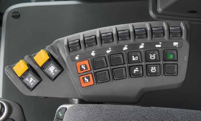
If the combine is fitted with 4D SEPARATION, there are now four sets of doors. They can be operated in the same manner as the standard rotor cover plates. Either from the armrest or from the CEBIS screen.
In situations where the straw is breaking up, it may be beneficial to close the rotor cover plates to reduce the sieves being overloaded. To find the correct rotor speed, start with the CLAAS settings in CEBIS and then adjust the rotor speed to suit the conditions on the day.
The straw will only travel along the rotor at one speed. This will differ for every crop, machine and condition.

Depending on the machine, there can be 2 sets or 4 sets of rotor cover plates. These are opened or closed in CEBIS or on the armrest.
AUTOSLOPE and 4D are activated in CEBIS.

Cleaning

Tips:
Clean the preparation trays daily, this will help keeping a clean sample.
When removing the prep trays for cleaning, blow off the top of the gear box area to remove any chaff and dust.
The preparation pan is the first part of the cleaning system that the grain will come into contact with. Its function is to separate the grain and the chaff. The grain is heavier and therefore goes to the bottom, the lighter chaff goes to the top.
It is important that this is kept clean, to allow this to happen effectively. A dirty preparation pan will cause a poor sample and reduce output.
Depending on machine type, it may be fitted with either 5 or 6 preparation trays.
Hybrid LEXION trays are the same size, therefore can be located into any of the available slots.


Both the top and bottom sieves are adjustable from 0 – 20mm in the cab.
The sieves need to be open enough to cope with high volumes of grain. With wide sieve settings, there is a need for high wind speed. It is recommended that the sieves are only adjusted by 1mm at a time.
The returns should be monitored regularly both in terms of volume and composition. If fitted the returns monitor can be adjusted in CEBIS. The volume of grains in the returns (1) and the volume of material (2).
If the shaft is not visible, returns are excessive.


The straw chopper can be engaged and disengaged from work by operating the buttons on the rear of the machine or via CEBIS. The spreader hood cannot be moved if the chopper is still rotating.
Turn switch up or down this will move the spreader into the first position if it needs to be moved further, release the switch and turn it again.
Make sure the hood has stopped moving before releasing the switch. All the settings for the powerspreader can be set from the CEBIS screen. make sure not to spread too wide.
1. Decrease the concave gap

Grains in the ears
Poor straw quality
2. Increase the drum speed
3. Engage the concave bar
1. Reduce drum speed
2. Open the concave
Threshed grains in the returns
Unthreshed ears in the returns
Other grains
Returns volume below 40%
Returnsquantity and quality of grains OK
Returns volume above 40%
1. Open the lower sieve
1. Increase the forward speed
2. Close the disawning flaps
1. Increase the fan speed
1. Close the lower sieve or open the upper sieve
1. Close the upper sieve or open the lower sieve

When deciding what to adjust on the combine to reduce the amount of loss, it is important to understand where the loss is coming from and what is acceptable.
At the front of the machine
Is loss occurring before or after the cutterbar knife?

At the rear of the machine
If it is happening before, it is not cutterbar related.
Tips:
Always check the losses behind the combine after making an adjustment and then set up the monitors to show what is happening.
In the CEBIS machine menu, you will find an optimization guide for operator setting assistance - the same guide can be found in the CEMOS Advisor App.
Are the losses acceptable?
Are they coming from the sieves and/or rotors?
Adjust the reel position or check the knife for damage or wear.
Fit lifters to lift any laid crop or place cutterbar into a flex mode.
If losses are excessive, make sure to check head losses in the crop in-front of the Lexion, this will give the operator a more precise idea as to where the losses are originating.
After adjusting the combine, make sure that the monitors also reflect what you will accept as a loss.
Adjust monitor sensitivity so that the blue area is approaching the limit lines, the white line. This is particularly important when running CRUISE PILOT and CEMOS AUTOMATIC.
Where are the losses coming from?
To work out what is coming from the rotors; engage the chaff spreader and disengage the chopper, then carry out a check behind the combine and lastly, count the grains on the floor.
To check the losses from the sieve; disengage the chaff spreader and engage the chopper, offset the spreader and then count the grains.
Take into account what the grains look like (unthreshed heads etc.).
Now, make the corresponding adjustments.
Tips:
The easiest way to check for losses is in the swath with the chaff spreader and chopper disengaged.
Count the number of grains within a set area - a hand print can be a sufficient guide.


1.


For the FIELD SCANNER
> Select the steering symbol (1) turn on the steering, then select the sensor.
> To activate, press the AUTOPILOT button on the multi function control handle when you are lined up with the edge of the crop.
TIP: Make sure that the width of the cutterbar has been set in the front attachment menu. Adjust the sensitivity and offset so the FIELD SCANNER follows the edge of the crop.
> Press button (2) to change the detection area that the FIELD SCANNER will work within. It will light up as follows...
> Press once, left edge of the crop: indicator light will appear white.
> Press a second time, right edge of the crop: indicator light lights up green then press a third time. Wheel track indicator light flashes white and green.
TIP: If the LASER PILOT is not steering straight ahead, check the centralising and sensitivity first in the steering menu.


To turn on,
> Select (1)
> Select GPS
Make sure that the main screen for the GPS is on.
The Quick access menu (1) contains the “Reference track” menu (2). The recording process is started by selecting a track type.
The following reference lines can be created:
> A=B straight line
> A=B contour
> A+ angle
> Manual entry

Track planning
A=B straight line
> Drive to position and set point A (1)
> Drive to the end point and set point B (2)
> The reference line is created under the name A=B and the time stamp (3)


CRUISE PILOT adjusts the ground speed while combining. There are three different driving strategies that can be selected with CRUISE PILOT:

CRUISE CONTROL
(constant ground speed)

Performance
(constant throughput)

Throughput
(throughput with monitoring)
It is important that the “zero throughput” value is learnt daily or after adjustment to the feeder housing chains (see daily zeroing).


1. Turn on Master Switch
3. If in CRUISE CONTROL,
4. Set max speed
5. Set target throughput
7. Set CRUISE PILOT sensitivity
8. Learn zero throughput

To engage CRUISE PILOT, press the AUTOPILOT button on the joystick.
To de-activate CRUISE PILOT, either move the C-MOTION lever or tap the service brake pedals lightly.
To monitor CRUISE PILOT, locate the bottom of the CEBIS screen which displays the CRUISE PILOT limiting factor once in work. The machine will always have a limiting factor. For a more in-depth explanation, use the QR code on the rear of the booklet to view the operation video.
Use the QR code on the back of the booklet to get the video for setting up CEBIS in the field.
Make sure that the combine has crop going through it before pressing the AUTOPILOT button on the joystick.
If just using CRUISE CONTROL, (fixed ground speed) drive the combine into the crop at your desired speed then press and hold the AUTOPILOT button for 3 seconds, there will be a beep from the CEBIS screen. This speed is now saved.
If using performance mode (constant throughput), set the target throughput and then increase until you reach your desired throughput. Alternatively, drive into the crop until the desired throughput is reached, then press and hold the AUTOPILOT button for 3 seconds
- you will then hear a beep from CEBIS. The throughput is now saved.
If using the throughput mode, make sure that the loss & return monitors are adjusted accordingly. Be sure to check your losses!

The maximum layer height is reached

Maximum diesel engine output utilisation is reached

The diesel engine protection has responded

The maximum pre-set throughput is reached


The maximum pre-set ground speed is reached


The separation loss limit is reached

The cleaning system loss limit is reached
The returns grain limit is reached
The returns volume limit is reached
Adaption: The machine adapts to new harvesting conditions
The unloading mode is activated
The turning area is identified

The symbol displayed in “4” is the limiting factor of CRUISE PILOT.
Now adjust the relevant limiting value.
To set throughput with monitoring, drive the combine into the standing crop so that the loss monitors are full to the white line. Then check that this is what you accept as a loss.
During unloading, the CRUISE PILOT automatically changes to unload mode which gives a constant speed, this will can be up to 15% less than the current forward speed. The unload mode can be turned off in CEBIS. Use the QR code on the back of the booklet to get the video for setting up CEBIS in the field.


LEXION now has the option to make CEMOS
When changing the crop type, make sure that CEMOS is not available for all crop types.
Grain
No Flex, Rigid Cutterbar using sensor bands for AUTO CONTOUR detection.
Flex Manual
Full Flex Cutterbar knife but with a set level AUTO CONTOUR
Switching between Grain and Flex modes when change is required on the move (from standing too laid crop).
Full Flex with fully adjusting AUTO CONTOUR, Cutterbar is moving both knife and feederhouse, AUTO FLEX try’s to always cut at the lowest possible ground point, best for short crops.


Threshing won’t engage and none of the hydraulics are working.
Check that the road travel switch is not engaged.
No AUTOMATICS will engage
Make sure the cutterbar is in work and the cutterbar is below the working position.
The machine will not change gear.
Make sure that the multifunction lever is in its neutral position and the automatic park brake has not been turned off, then briefly press the gear shift switch once to select a gear.
How to set the cutterbar park position.
Disengage the cutterbar and the threshing, with the engine running, press and hold the cutting height button on the multi function handle until there is a beep from CEBIS.
The machine goes off course when AUTOPILOT is engaged.
Make sure that the FIELD SCANNER settings are correct in the CEBIS settings.
Getting a poor sample after many adjustments.
Check that the preparation floor are clean.
The machine is lacking performance.
What are the settings in CEBIS, what are the crop and field conditions. When chopping check that the knives are sharp, the belt is set correctly.
It is even more important to get a good cut and feed into the combine. Check the knife and fingers regularly, paying particular attention to the knife to finger gap.
For the VARIO cutterbar, the skids under the bar must be raised into their highest position. This will also reduce the amount of soil sticking to the underside of the cutterbar. For the CONVIO FLEX cutterbar, change the mode to a flex mode.
These are more likely to enter the combine in a wet harvest, it is vital that the stone trap be emptied at least daily. The more irregular the conditions, the more frequently this should be done.
This is your first indication that further cleaning inside the combine may well be required. When cleaning the rest of the combine, follow the path of grain through the machine, and open covers as you come to them.
Under the concave is the preparation pan
This will become dirty as wet grain and soil passes over it. The dirtier it becomes, the less effective it will be, and hence, the dirtier the sample will become. With wet grain, it is important to try and keep to a cleaner sample than normal.
Check that the APS concaves are clean. To do this, simply open the concave to 50mm before switching off and emptying the stone trap.
Reduce the flow into the unloading auger by shutting down the baffle plates on both cross augers in the grain tank. This will reduce the load on the unloading system.
It is possible for material to stick to the return floor under the rotors. This then impedes the flow of grain back to the preparation pan and affects the sample. Check the pan regularly and clean as required.
It is also likely that dirt will build up in the turret auger. This can and should be checked regularly through the inspection doors, and cleaned if required.
This can be accelerated when chopping wet straw due to the increased levels of soil in it. Check the condition of the blades regularly. Do not forget to check the stationary blades.
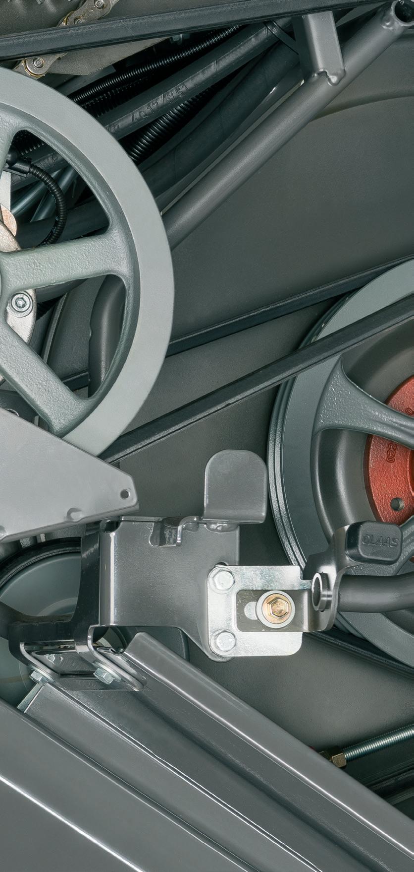
This adds an extra load to the chopper drive. Regularly check the tension of the drive belts and the blade condition. Do not forget the 2 ‘stops’ at either end of the main tensioner.
If the shear bolt on the unloading drive fails, 130l/s unloading system
This is often the first sign that either the slides in the tank are too high, or there is too much dirt in the system, check auger timing.

At the beginning of the season before the combine is used, it is advised that certain procedures are learnt. This is done by navigating to the ‘service menu’ then ‘learning procedures of machine’. Follow the prompts on the CEBIS screen.
fingers are perfectly matched guaranteeing outstanding performance capacity fingers have a specific, predeterdesigned into them. This means double fingers will break at subjected to a given force. This and knife drive mechanism to be kept to a minimum. knife damage harvesting double fingers. count.
1 A perfect match.
CLAAS ORIGINAL double fingers are perfectly matched to the CLAAS cutting system, guaranteeing outstanding cutting over a long period.
The advantages for you:
−Clean cutting
−Perfect knife guidance
−Optimal use of machine's performance capacity
2 Well thought-out design.
CLAAS ORIGINAL double fingers have a specific, predeter mined breaking point designed into them. This means that, instead of deforming, the double fingers will break at this precise point when subjected to a given force. This prevents damage to the knife and knife drive mechanism and also allows repair times to be kept to a minimum.
The advantages for you:
−A
−F
−Reduced downtime
3 Multiple-hardened cast steel.
Robust double fingers play a key role in ensuring a successful harvest. CLAAS ORIGINAL double fingers are subject to only minimal deformation, allowing you to avoid unwanted machine downtime.
The advantages for you:
−Particularly long-lasting
−Extremely rugged
3 Multiple-hardened cast steel. Robust double fingers play a key successful harvest. CLAAS ORIGINAL are subject to only minimal deformation, you to avoid unwanted machine downtime.
The advantages for you:
4 Precise knife guidance. The knives are guided with minimal resistance, yet outstanding accuracy. As well as producing a perfect cut, the precision of the knife guidance extends the service life of the equipment.

The advantages for you:
−Perfect cutting
−Maximum reliability
−Particularly long-lasting
−Extremely rugged
4 Precise knife guidance. The knives are guided with minimal outstanding accuracy. As well as cut, the precision of the knife guidance service life of the equipment.

The advantages for you:
−Perfect cutting
−Maximum reliability
CLAAS ORIGINAL parts compared. Find out more here: original.claas.com

LEXION 8000-7000
UKMSC8XHYBRID
Scan the QR code to direct you to the CLAAS LEXION YouTube playlist. Available on the App Store and the Google Android Store.

CLAAS UK Ltd.
Saxham Business Park
Bury St Edmunds
Suffolk IP28 6QZ www.claas.co.uk


CLAAS Telematics

CLAAS CEMOS Advisor
LEXION 8000-5000
YouTube Playlist
