PHYSICS
Peter DeFreitas
Reviewers: Lenore Dunnah, Raphael Johnson
26 Circuits and components
Electric current from a cell or generator can only flow in a complete circuit. Circuit diagrams are a useful way to show the arrangement of components in an electrical circuit. Each component of the diagram is represented by a circuit symbol.
Components of a circuit may be connected in series or in parallel. Series circuits only provide one path for the current to flow, but parallel circuits have junctions where the current divides and then rejoins after passing through branches
Cells, batteries (groups of cells) and electrical generators are used to provide the power necessary to drive current around a circuit against the resistance offered by its components.
Learning objectives
• Draw circuit diagrams using circuit symbols representing various components and devices.
• Understand why ammeters have negligible resistance and voltmeters have infinite resistance
• Understand how to connect ammeters and voltmeters with correct polarity.
• Differentiate between series and parallel connections in an electrical circuit and the relation between the currents and voltages associated with them.
• Combine cells in series and in parallel and state the charge rating of a cell in amp-hours
• Distinguish between primary and secondary cells and compare the zinc-carbon dry cell to the lead-acid cell stating the advantages of each.
• Draw a circuit showing how a secondary cell can be recharged from the AC mains supply.
• Explain the concept of resistance and relate it to length and cross-sectional area.
• Calculate the total resistance of resistors in series and of resistors in parallel
• Use a variable resistor as a rheostat and as a potential divider
• Define Ohm’s law and relate it to the I–V characteristic of various types of conductors.
• Understand the relation between resistance and pd ratios for resistors in series.
• Perform calculations involving voltage, current, resistance, energy, and power for complete circuits.
Some important circuit symbols
• Voltmeter – A device that measures the potential difference between two points.
• Ammeter – A device that measures the current flowing through a point.
• Galvanometer – A device that detects, measures and determines the direction of very small electric currents.
• Resistor – A component that opposes the flow of current.
• Rheostat – A resistor with a resistance that can be altered, usually by a slider control.
• Light-dependent resistor (LDR) – A resistor having a resistance that decreases with increased light intensity.
• Thermistor – A resistor having a resistance that changes with temperature (the resistance generally decreases with increased temperature).
• Diode – A device that normally allows current to flow through it in one direction only.
• Light-emitting diode (LED) – A diode (electrical valve) that emits light when current flows through it in a particular direction (see Chapter 28).
• Fuse – A metallic resistance wire placed in series with a device, which protects a circuit from excessive current by becoming hot, melting and disconnecting it.
• Circuit breaker – An electromagnetic switch which protects a circuit from excessive current by disconnecting it.
• Transformer – A device that increases (steps up) or decreases (steps down) an alternating voltage.
cell battery of 3 cells battery pack of several cells DC supplyAC supply AC supply voltmeter ammeter galvanometer galvanometer resistor
variable resistor or rheostat thermistor switch conducting wire crossing wires (not connected) connected wires speaker microphone
push button switch
earth filament lamp lampelectric buzzerelectric bell
or or
Gen fuse
transformer motor generator diode
light-dependent resistor
electrolytic cell or voltameter
light-emitting diode (LED)
For symbols used in electronic circuits see Chapter 28
Series and parallel connections
Connection of ammeters and voltmeters
Ammeters are connected in series with a component to measure the current through it. They must therefore have negligible resistance so as not to affect the current they are measuring. An ideal ammeter has zero resistance
Voltmeters are connected in parallel with a component to measure the potential difference across it. Current will divert through the voltmeter and this can alter the current through (and therefore the pd across) the component being investigated. The voltmeter should therefore have a very high resistance to keep this diversion to a minimum. An ideal voltmeter has infinite resistance.
For some devices or components such as ammeters and voltmeters, the polarity of their terminals must be considered when connecting them in a circuit. Figure 26.2 shows that current leaving the + terminal of a battery must always enter through the + markings on an ammeter or voltmeter.
Current flow in series and parallel circuits
Figure 26.3 shows how current flows in series and parallel connections in circuits. Current flows from the positive to the negative terminal of the battery through the external circuit (circuit outside the battery).
In the series circuit of Figure 26.3a, current has only one path around the circuit. The current is therefore the same at all points in the circuit and each of the ammeters will register the same reading. In the parallel circuit of Figure 26.3b, current leaving the positive terminal of the battery divides into two branches on meeting point X. Since charge must be conserved, the charge flowing into the branch point must be equal to the charge leaving it. The current registered by ammeter A1 is therefore equal to the sum of the currents registered by ammeters A2 and A3. These branch currents will then rejoin at the next branch point Y and flow through ammeter A4 before returning to the cell through its negative terminal.
Figure 26.3 Current in series and parallel circuits
Potential difference (voltage) across components in series and parallel circuits
Figure 26.4 shows the pds existing in series and parallel circuits. Since voltmeters are always connected in parallel with the component they are measuring, the wires connecting them in the figures below are printed in black to distinguish them from the circuits they are investigating. In both circuits, the cell sets up a potential difference (potential drop) equal to its emf across the group of resistors.
In the series circuit of Figure 26.4a, part of the fall in potential occurs through the first resistor and the remainder through the second. Each resistor only obtains a share of the total pd across the combination. The emf of the cell is therefore equal to the reading, VE, and this is equal to the sum of the readings V1 and V2
= 0.9 V
= 1.5 V
Example illustrating the TWO potential drops
In the parallel circuit of Figure 26.4b, the pd across the group of resistors measured as VE is the same as the pd across the individual resistors measured as V1 and V2. There is only ONE potential drop across the parallel section.
Figure 26.5 shows a circuit where a combination of two resistors connected in parallel is joined in series to a third resistor. Note that in this case, there are TWO potential drops across the resistors. The first drop is across the parallel combination and the second drop is across the resistor in series with it. V
= 0.5 V
potential = 1.0 V emf = 1.5 V
potential = 1.5 V potential = 1.5 V pd = 1.0 V
potential = 0 V potential = 0 V
Joining cells to make batteries
Figure 26.6 shows total emfs produced by cells in series and by cells in parallel.
• Series connection – When cells are joined in series, the total emf is the sum of their emfs.
• Parallel connection – Sometimes it is useful to connect cells of equal emf in parallel. The total emf is then the same as the emf of one of the individual cells.
Although parallel connection of cells does not increase the total emf, it has the following advantages:
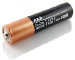
• To produce a particular current from a two-cell parallel combination, the rate of reaction in each cell would only be half as high since each cell would have to produce just half the current. Similarly, for a three-cell parallel combination, it would be one third as high. Combining cells in parallel is therefore useful if the current demand of the circuit is greater than that which can be produced by an individual cell. Several AAA 1.5 V cells can be used in parallel instead of one larger D 1.5 V cell (see later in this chapter for types of cells).
• Since the current demand on each cell is less, parallel connection of cells will last longer before the battery runs flat. This is particularly convenient when hunting at night or when using under water lights for diving. If, for example, each cell used individually will run flat in ½ hour, then two of the same cells in parallel will last 1 hour. The two cells in total deliver the same energy for the hour, but the user avoids having to replace the flat cell after 30 minutes.
Charge stated in amp-hours (A h)
The charge stored in a battery is often stated in amp-hours (A h) instead of in coulombs (C). It is then easier for users to estimate how long they will last. For example, a battery rated at 80 A h can deliver 1 A for 80 hours or 4 A for 20 hours.
Since Q = It
1 A h = 1 A (60 × 60) s = 3600 A s = 3600 C
Primary and secondary cells
A primary cell is a source that converts chemical energy into electrical energy by a non-reversible chemical reaction.
A + B C + D + electrical energy
A secondary cell (also known as an accumulator or storage cell) is a source that converts chemical energy to electrical energy by a reversible chemical reaction.
A + B C + D + electrical energy
electrical energy + C + D A + B
To charge a secondary cell, current must flow through it in the opposite direction to that in which it delivers current during discharge. This means that current enters through the positive terminal of the cell and leaves through its negative terminal when connected to a charging device.
Discharging: chemical energy electrical energy
Charging: electrical energy chemical energy
The zinc-carbon dry cell

Figure 26.7 shows a zinc-carbon dry cell.
• Chemical reaction between the ammonium chloride and the zinc produces the electricity.
• The manganese oxide and carbon mixture is used to prevent polarisation (the collection of hydrogen bubbles forming around the carbon rod), which would add to the unwanted internal resistance of the cell.
protective metal cap
graphite rod (positive pole)


insulating seal prevents evaporation of electrolyte
mixture of manganese oxide and carbon, enclosed by a paper separator
ammonium chloride paste (electrolyte)

insulating case with advertising label
zinc case (negative pole)
The lead-acid accumulator – a secondary cell
The lead-acid accumulator is the battery generally used in vehicles. Unlike the zinc-carbon dry cell, it is rechargeable and can produce the high currents required by the starting motor of a vehicle. Although the structure of the lead-acid cell is not a requirement of the CSEC syllabus, you must be able to compare its characteristics to those of the zinccarbon dry cell (see Table 26.1). The following Figures will give you a better understanding of some of the accumulator’s characteristics.
Figure 26.8 shows a lead-acid accumulator. Figure 26.9 a shows one lead-acid cell, and Figure 26.9 b shows how a typical accumulator of terminal voltage 12 V is comprised of SIX 2 V cells joined in series.
a lead-acid cell
a lead-acid cell
+ pole: lead oxide when charged (multiplate positive electrode)
+ pole: lead oxide when charged (multiplate positive electrode)
dilute sulfuric acid – electrolyte
dilute sulfuric acid – electrolyte
porous insulator
porous insulator
insulating case
insulating case

– pole: lead when charged (multiplate negative electrode)
– pole: lead when charged (multiplate negative electrode)
b lead-acid battery of six cells in series
thick wire thick wire
thick wire thick wire
+–
b lead-acid battery of six cells in series +–

conducting bar joining cells in series
conducting bar joining cells in series
Table 26.1 compares the features of the zinc-carbon cell and the lead-acid cell.
Table 26.1 Comparison of zinc-carbon cell and lead-acid cell
Characteristic Zinc-carbon dry cell Lead-acid cell
Rechargeability not rechargeable rechargeable
Terminal voltage 1.5 V 2.0 V
Internal resistance high (0.5 Ω) low (0.01 Ω)
Maximum current maximum current drawn is typically less than 1 A > 400 A
Electrolyte ammonium chloride paste dilute sulfuric acid
Portability small and light large and heavy
Advantages of the zinc-carbon dry cell over the lead-acid cell
• More portable since it is small and light, whereas the lead-acid accumulator is large and heavy.
• Can be inverted (turned upside down) without spillage because its electrolyte is in the form of a paste.
• Batteries of various voltages can easily be compiled by arranging the cells in series or in parallel.
• Less costly.
Advantages of the lead-acid cell over the zinc-carbon dry cell
• Unlike the zinc-carbon cell, these can produce much larger currents due to a higher rate of reaction:
❍ the ions have greater mobility because the electrolyte is a liquid and not a paste
❍ the electrodes consist of several plates, allowing greater surface area for reaction.
• Has a much lower internal resistance.
• Unlike the zinc-carbon cell, it is rechargeable
• Has a longer life
• Provides more electrical energy than the dry cell.
Different types of dry cells
Alkaline cells have potassium hydroxide as their electrolyte.
Lithium-ion cells are used in UPS (uninterrupted power supply) systems to provide energy to offices during power outages and power fluctuations. They are also used in laptop computers, cell phones and digital cameras. Electric vehicles utilise lithium-ion batteries since they can store more charge than a lead-acid accumulator and they have a longer life.
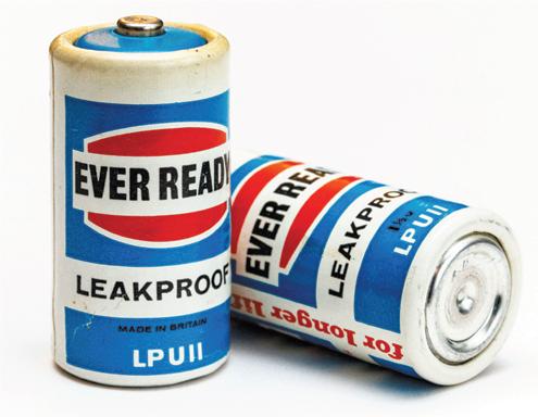
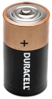
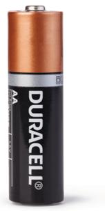
Figure 26.10 shows examples of different types of dry cells. The cylindrical ones shown here are all 1.5 V.

Charging an accumulator from the AC mains supply
Figure 26.11 shows how an accumulator can be charged from the AC mains supply.
• A step-down transformer (see Chapter 31) is used to reduce the voltage from the mains supply.
• A diode is used to rectify the AC to DC (see Chapter 28).
• The variable resistor is adjusted to bring the pd across the battery to just above 12 V.
• The charging current is directed into the positive terminal of the battery.
1 A device uses a power of 48 W and operates on a current of 4.0 A from a supply storing 120 A h of charge. Determine:
a the voltage of the supply
b the charge stored by the supply in coulombs
c the time for which the average current of 4.0 A flows.
a P = VI ∴ V = P I = 48 4.0 = 12 V
b Q = 120 A h = 120 A × (60 × 60)s = 432 000 A s = 432 000 C
c Q = It ∴ t = Q I = 432 000 4.0 = 108 000 s or 108 000 (60 × 60) = 30 hours
Alternatively, using charge in A h: t = Q I = 120 4.0 = 30 hours
Resistance
Resistance is a measure of the opposition provided to an electric current; it is the ratio of the pd across a conductor to the current through it.
A resistor is a device that has resistance.
Explanation of electrical resistance in metals
When electrons flow through a conductor, they are obstructed by vibrating cations (positively charged atoms) in their paths. These vibrating cations therefore obstruct the rate of flow of the electrons and hence the current.
Effect of length and cross-sectional area on resistance
The resistance, R, of a conducting wire is proportional to its length, l, and inversely proportional to its cross-sectional area, A:
The resistors shown in Figure 26.12 are made of the same material. R3 has the greatest resistance and R1 has the least resistance.
Adding resistors
Connected in series R = R1 + R2 + R3
Connected in parallel 1 R = 1 R1
+ 1 R2
+ 1 R3
For the case where only TWO resistors are in parallel: R = product sum R = R1 × R2 R1 + R2
• When resistors are connected in parallel, their total resistance is less than that of any of the individual resistors of the combination.
• When two identical resistors are in parallel, their combined resistance is half the value of any of the individual resistors of the combination. If each is of resistance 10 Ω, then the total resistance is 5 Ω.
2 Determine the total resistance of each of the following combinations.
a 4 Ω and 3 Ω in series
b 6 Ω and 4 Ω in parallel
c 4 Ω, 5 Ω and 20 Ω in parallel.
a R = 4 Ω + 3 Ω = 7 Ω
b R = product sum = 6 × 4 6 + 4 = 24 10 = 2.4 Ω
c
3 Determine the total resistance between X and Y of each of the combinations of filament lamps shown in Figure 26.13, if the resistance of each lamp is 2.0 Ω.
HINT: To fast-track these calculations, the resistance of any set of resistors in series within a branch can be interpreted as the sum of the individual resistances in that branch.
The variable resistor
Figure 26.14 shows a variable resistor being used as a rheostat and as a potential divider.
Rheostat – This controls the current in a circuit. When used as a rheostat, only terminals A and C are connected in the circuit. By adjusting the position of the slider, the total resistance and therefore the current in the circuit can be varied; the voltage (pd) across a component connected in series with the rheostat can be varied but can never be zero.
Potential divider – This puts a fraction of a voltage across a component. When used as a potential divider, all three terminals are connected in the circuit. A voltage is applied to the variable resistor between the terminals A and B, and a part of this voltage is applied to a component connected in parallel with the resistor coil between terminal A and the slider at terminal C. Used in this way, the pd across a component can be reduced to zero
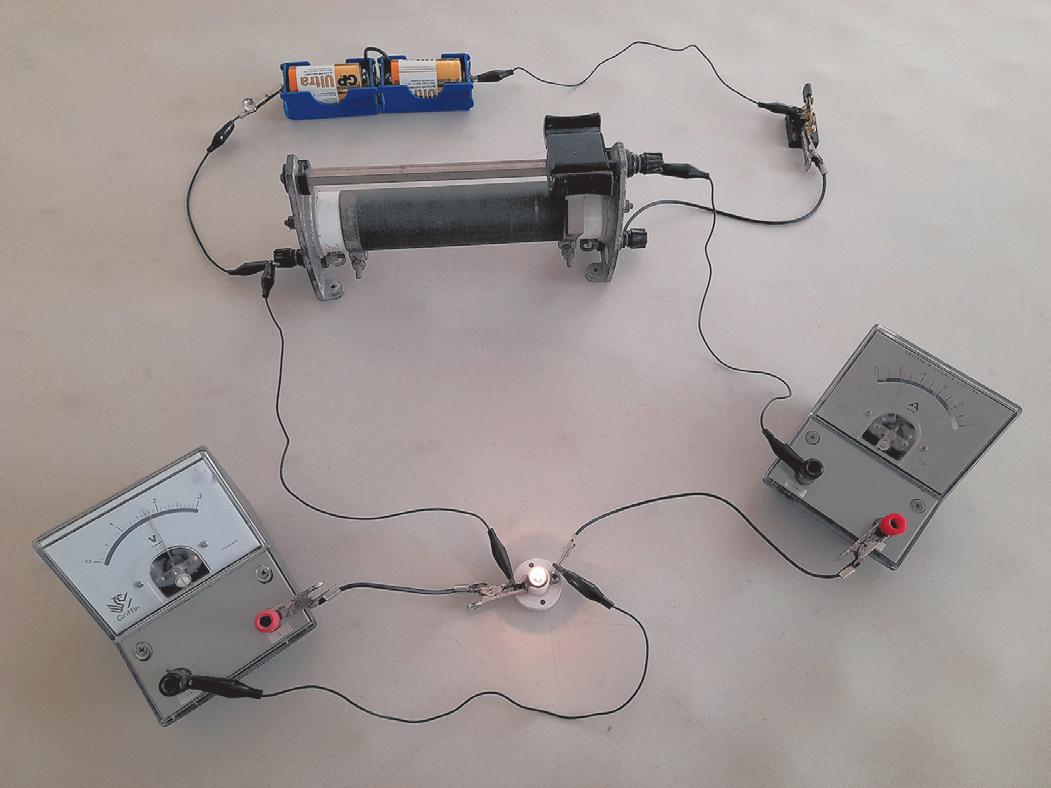
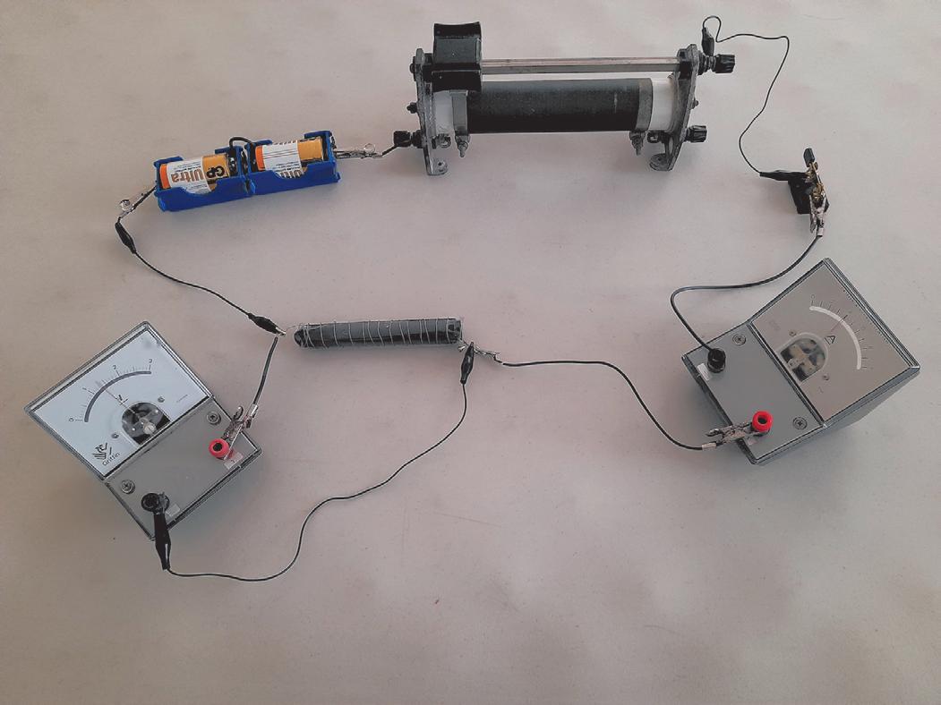
Figures 26.15a and 26.15b show arrangements of a variable resistor being used as a rheostat and as a potential divider, respectively. Figures 26.16a and 26.16b show practical arrangements of the same circuits.
Ohm’s law and I–V characteristic curves
Ohm’s law: Provided the temperature remains constant, the current, I, through an ohmic conductor is proportional to the potential difference, V, between its ends.
∴ V = IR … where the constant of proportionality, R, is the resistance of the conductor.
Experiment to determine I–V characteristics of various components
The relationship between the current, I, through a component and the potential difference, V, across it can be investigated using the circuits shown in Figure 26.15. Lamps and diodes behave differently at low voltages than they do at higher voltages and so circuit 26.15b, which can also measure the low voltages, is preferred when investigating these components.
An initial pair of readings of I and V is taken.
• By adjusting the variable resistor, five other pairs of readings of I and V are taken.
• The connection between the terminals of the battery and the circuit is reversed and the process is repeated.
• A graph of I against V is plotted.
Figure 26.16 Practical circuits for investigating I–V relationships utilising a variable resistor. a as a rheostat. b as a potential divider
Graphs of I against V for a component are called the I–V characteristics of the component.
Figure 26.17 shows the I–V characteristic curves for different components.
a metallic conductor at constant temperature (ohmic)
b lament lamp (non-ohmic)
c semiconductor diode (non-ohmic)
Figure 26.17 I–V characteristic for different components
d aqueous solution of copper sulfate using copper electrodes (ohmic)
