8 minute read
A few structural geology concepts for sedimenthosted Copper exploration
A case study from the Cashin Mine in the US
by Dr Molly Turko, Structural Geology Expert & Dr Ali Jaffri, CEO at Applied Stratigraphix
Advertisement
Sedimentary rocks host approximately 25% of the world’s Copper. Sediment-hosted stratiform Copper deposits were a key target for exploration in the United States that peaked during the 1940-1970s. During these times, explorers were primarily focused on understanding concepts of geochemistry and hydrogeology while structural geology often took a back seat. Recent field work by Applied Stratigraphix on Copper-bearing Triassic-Jurassicaged strata of the Colorado Plateau, US, led to the conclusion that up to 80% of minerals are being deposited along fracture and fault networks. Concepts in structural geology and sedimentology have come a long way since the peak of exploration thanks to new technology, 3D seismic data as an example, and can be applied to future exploration of mineral deposits. Although these concepts might be simple to trained structural geologists, they will be vital to any sedimenthosted metal prospect and worthwhile to understand, even for a non-geologist.
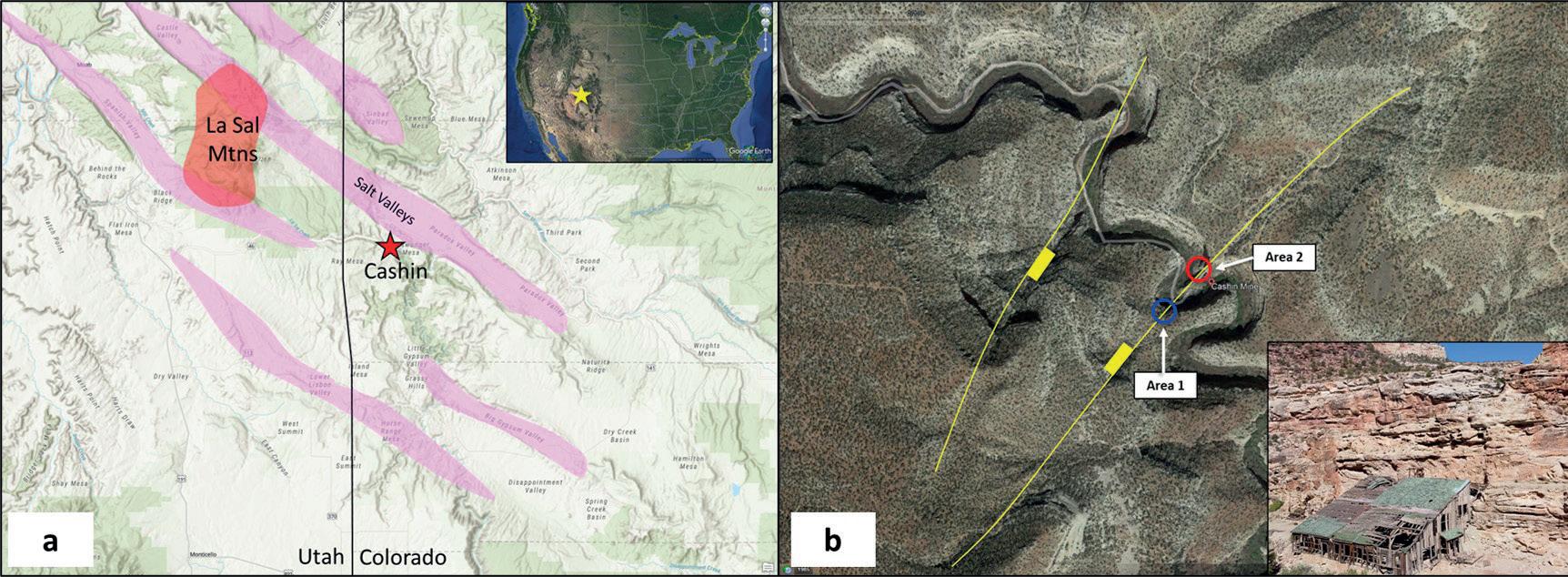
These concepts include understanding the role of mechanical stratigraphy - the impact of fault geometries on fracture intensity and understanding how perturbed stress fields can impact fracture orientation and intensity. Before we get into the details of each of these concepts, let’s examine some of the observations from the field. We will focus on the Cashin Mine in southwest Colorado (Figure 1a). Cashin is a sediment-hosted copper and silver mine in the Paradox Basin that was discovered in 1896 with intermittent production from 18981946 with the last recorded production in 1976. The ore grade ranged from 7-12% copper and 8-134 oz (227-3800 g) of silver per ton, with one high grade shipment of native copper containing 89% copper. (https://www.mindat.org/loc-22531.html).
The copper at the Cashin Mine is hosted in the Jurassic age Wingate eolian succession that ranges between 290-300 ft (88-92 m) (MacIntyre, 2006). It’s capped by the Kayenta Formation which consists of fluvial sandstones and mudstones deposited in dryland ephemeral streams (Priddy and Clarke, 2021). Below the Wingate sits the Chinle Formation which consists of fluvial floodplain conglomerates, sandstones and mudstones (Hartley and Evenstar, 2017). The Kayenta and Chinle show some local bleaching, while the Wingate shows widespread bleaching of the sandstone. This bleaching occurred as buoyant hydrocarbons from deep in the basin moved along faults and into more permeable units which dissolved the iron oxides coatings from clasts within sandstone.
Prior to the Laramide Orogeny, the Paradox Basin was impacted by the Pennsylvanian Orogeny. During this time, contractional tectonics impacted the southwestern US while evaporites precipitated in the Paradox Basin. The salt moved subsequently with deformation of the basin and deposition of Pennsylvanian clastics resulting in linear salt anticlines (Figure 1a). The normal faulting observed at the Cashin Mine, occurred later during the Laramide Orogeny as some of these deeper salt anticlines collapsed. These faults then acted as great conduits for hydrocarbon migration followed by later migration of brines that provided the Chloride complexes needed to mobilize Copper. This later fluid flow event occurred during the Mid- to Late-Tertiary and could be related to a nearby igneous intrusion of the La Sal Mountains as well as the Colorado Plateau Uplift and increased hydrologic gradient. Copper carried by oxidizing, chloride complex-rich brines moved along faults and fractures till it encountered reductant in the form of bitumen, pyrite and organic-rich interdune microbialites.
The main fault at the Cashin Mine is oriented northeast-southwest and drops down to the northwest. A second fault also oriented approximately northeast-southwest drops down to the southeast creating a graben-like structure and linking with the Cashin Fault (Figure 1b). Fractures were studied in two field areas, one along a cross-sectional view of the Cashin Fault (Area 1) and one along strike of the fault (Area 2) looking at internal deformation of the fault zone. Fault offset is estimated to be around 66 ft (20 m) at the Cashin site. An intense zone of fracturing, about 20 ft (6 m) wide, is present at Area 1. Fracturing and faulting continue away from the main fault zone but with less intensity. Where fault and fracture planes are exposed, mineralization is apparent and hard to miss with Malachite and Azurite hues against the bleached sandstones (Figure 2a). It is obvious that much of the mineralization prefers the fracture/fault planes, however in a few areas the Malachite does precipitate into more permeable units (grainflow facies) (Figure 2b). Observations in Area 1 showed the mineralization was preferential to the fracture networks related to the immediate faulting and the damage zones away from the faults.
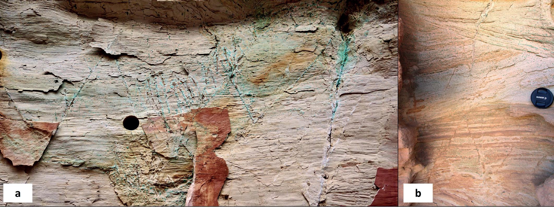
Area 2 exposes along-strike deformation of the Cashin Fault where much of the mining efforts commenced. What is left are exposed fault planes that have been mined out and some remaining brecciated fault blocks. Figure 3a shows an exposed hanging wall that was dug out leaving behind remnants of oxidized copper and iron minerals along with slickenlines indicating normal slip. Figure 3b shows a block of fault breccia speckled with azurite and malachite. Notice that in both of these figures, the mineralization is restricted to the fault and fracture planes whereas the matrix rock shows significantly less mineralization. As we continued to explore and observe the rocks surrounding the Cashin Mine, it became very apparent that identifying the faulted and fractured areas would have been incredibly significant to the success and development of this mine. This led us to think about several key structural geology concepts that could aid in future exploration and development projects focused on sediment-hosted metals including mechanical stratigraphy, fault geometries, and perturbed stress fields.
Mechanical stratigraphy
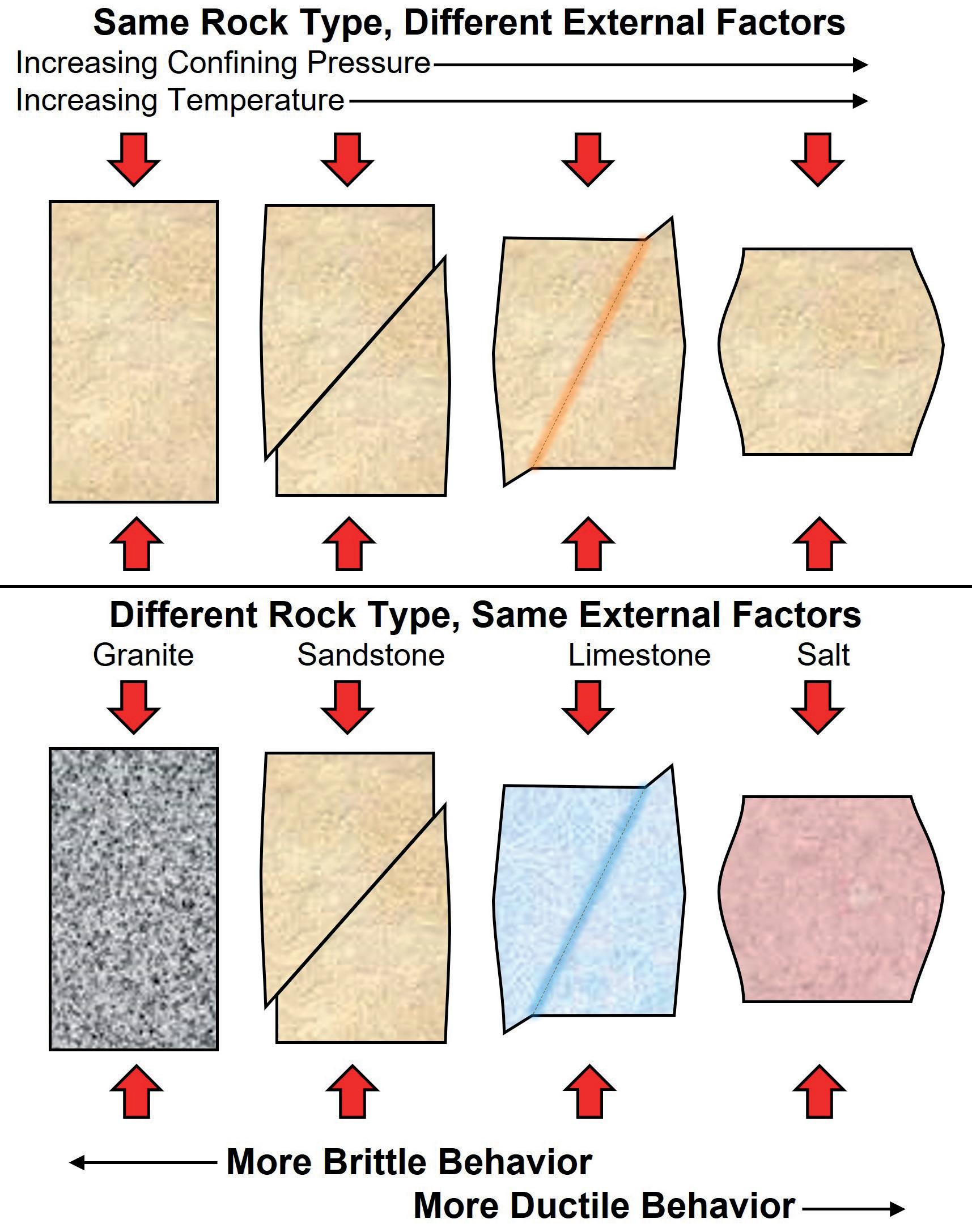
After observing such a strong structural control on deposits at Cashin, it is worthwhile to review a few structural geology concepts that may aid future exploration and development. These include mechanical stratigraphy, fault geometries, and perturbed stress fields. Mechanical stratigraphy represents the mechanical properties of the rock, the thickness of the mechanical layers, and the frictional properties at the boundaries (Ferrill et al, 2014). The terms brittle verse ductile are common language when referring to mechanical stratigraphy and can be impacted by mineralogy, depositional texture, porosity, and competence. It is also important to note that the term brittle should be regarded as a behavior and not an inherent rock property. In other words, it refers to how much the rock will deform before failing or breaking. Both internal and external factors can impact the brittleness of a rock. As an example, external factors, such as higher pore pressure, higher stress differential, and/ or a higher strain rate, can all increase brittle behavior. However, an increase in confining pressure and/or high temperature can result in more ductile behavior. One of the biggest internal factors impacting brittle behavior is the mineralogy of a rock. Generally speaking, a rock consisting of quartzite or chert would be considered very brittle, followed by dolomite, sandstone, limestone, then mudstone. However, the internal structure can also impact brittle behavior such as the grain size, grain sorting, cement type, porosity, and any pre-existing weaknesses or heterogeneity. Figure 4 illustrates some of these concepts. By understanding the mechanical

↑ Figures 5a, 5b & 5c stratigraphy of a rock column, a geologist can start to predict where they might find a greater degree of fracturing, whether the fractures are related to faulting or simply background fracturing. In regards to bed thickness, studies have show that there is a relationship between mechanical bed thickness and fracture spacing. The thinner the bed, the closer the fractures will be spaced.
Fault geometries
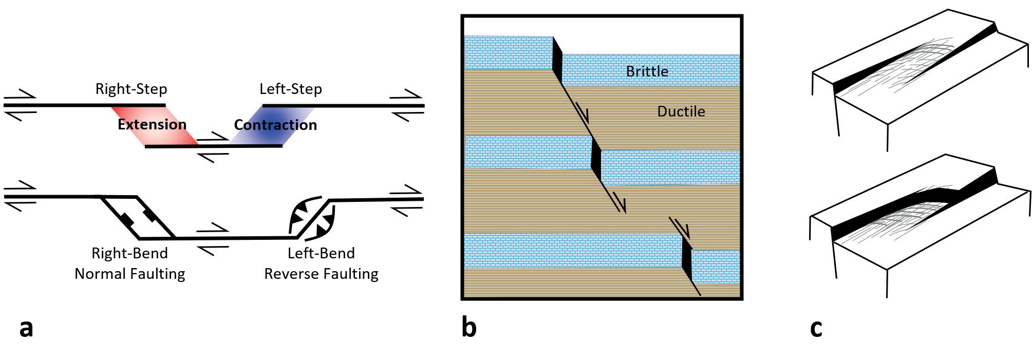
Detailed structure maps are vital to mineral exploration and one of the key factors to consider is the geometry of fault planes. Whether through field mapping, or subsurface data, mapping the fault planes can aid in finding areas of enhanced fracturing. Figure 5 illustrates how fault planes with an outer arc (outside bend) can create a zone of higher tensional strain whereas an inner arc (inside bend) can create a zone of higher compressional strain. Rocks tend to be weaker under tension (low confining stress) so the expectation would be a higher degree of fracturing in the tensional areas. Regions of extension and contraction can also develop along strike-slip faults as they step or bend along strike. A good rule of thumb is that a left-lateral fault with a left step or bend will result in extension, or a right-lateral fault with a right step or bend will result in extension. So, when the step or bend is in the same offset as the fault, right-lateral with a right step, the result is extension. If the step or bend has the opposite sense of offset the result is contraction. For example, a left-lateral strike-slip fault with a right step will result in a region of contraction, as will a right-lateral strike-slip fault with a left-step. These relationships are illustrated in Figure 6a and occur at all scales from the thin-section to large scale tectonics.

Relay ramps along normal faults are also regions where enhanced fracturing can be expected. As normal (or reverse) faults begin to initiate and grow laterally, they will interact with each other and eventually link up. Figure 6b illustrates this process for a normal fault. The region between the two faults is what is called the relay ramp and tends to become more highly fractured than the surrounding rock. Figure 6c illustrates how the mechanical stratigraphy can impact the geometry of the fault plane. The fault planes are shallower in more ductile units, and steeper in more brittle units resulting open ‘conduits’ adjacent to those brittle units as the fault begins to move. Those open conduits may become filled with minerals over a period of time making them an ideal spot to target. Although simplified, these rules of thumb on fault geometries can help with
↑ Figures 6a, 6b & 6c identifying areas of enhanced fracturing, which may very well be conduits for mineral rich fluids.
Perturbed stress field
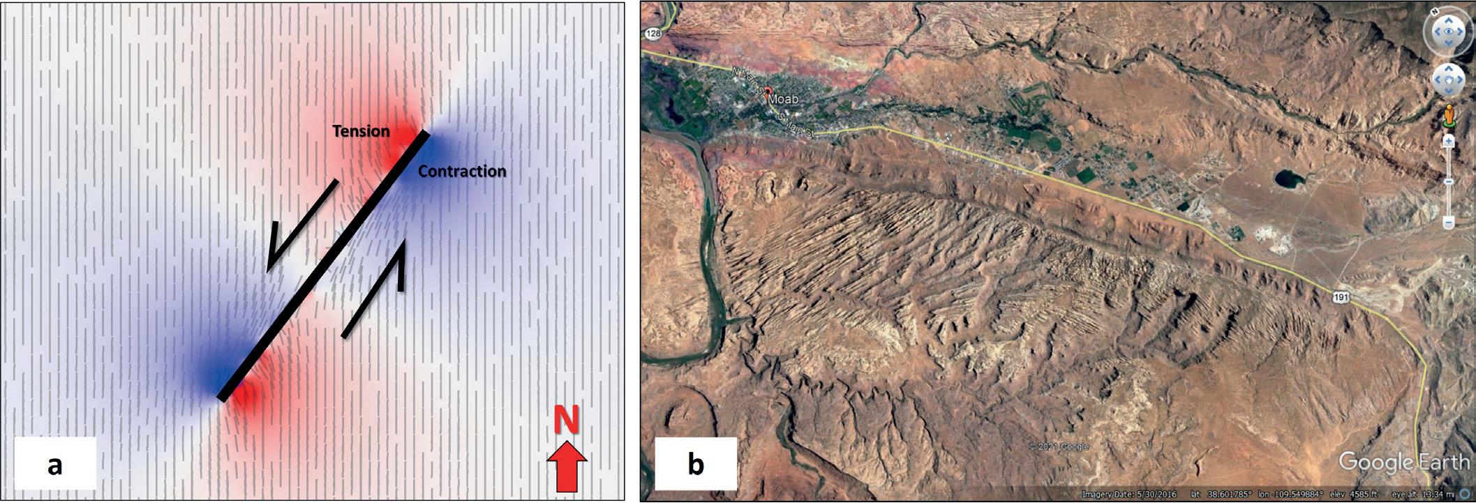
Perturbed stress fields occur when stresses deviate from regional expectations, usually due to some discontinuity such as a fault. Figure 7a shows a left-lateral strike-slip in map view. The regional orientation of the maximum horizontal stress is oriented north-south and represented by the vectors. Notice that as the vectors approach the fault they deviate from the regional north-south orientation. The fault also contains four quadrants, two extensional and two contractional. In the tensional quadrants, the vectors rotate to become perpendicular to the fault plane whereas in the contractional quadrant they become parallel. These regions where the vectors have become rotated represent the perturbed stress field. Figure 7b shows an image from Google Earth where fracture trends are becoming rotated around the Moab fault zone in Utah.
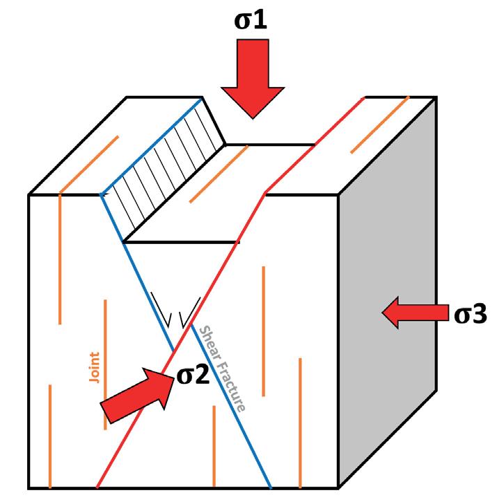
The orientation at which fractures form is dependent on the stress field at which they formed. Based on Andersonian Faulting Theory (Anderson, 1951), the general relationship between fractures/faulting and stress is shown in Figure 8. Mode I fractures, opening mode, tend to form parallel to ơ1 and ơ2 (maximum and intermediate principle stresses) and open in the direction of ơ3 (minimum principle stress). Mode II fractures (shearing mode) form close to +/-30 degrees to ơ1, parallel to ơ2, and perpendicular to ơ3. These relationships give some degree of predictability to fracture trends and orientations if the stress field is understood, whether that’s a regional stress field or a local perturbed stress field. If these fractures then become conduits for mineralized fluids, having a good understanding of the fracture orientations then becomes vital for exploration and development of a prospect.
Conclusion
These simple yet vital structural geology concepts may very well aid in predicting areas of enhanced fracturing. Just as we saw at the Cashin Mine, fractures were the primary conduits for hydrothermal fluids that carried the metals. Understanding the spatial relationships of a fault/fracture system backed by essential field work will lead to better exploration and development projects, particularly for sediment-hosted stratiform copper deposits. While geochemistry and hydrogeology led the way in historical production, structural geology may very well be king in future developments. C
References
The dynamics of faulting - E. M. Anderson, 1951
Control of mechanical stratigraphy on bed-restricted jointing and normal faulting: Eagle Ford Formation, south-central Texas - Ferrill et al., 2014
Fluvial architecture in actively deforming salt basins: Chinle Formation, Paradox Basin, Utah – Hartley and Evenstar, 2017
Fault-controlled hydrocarbon-related bleaching and sediment-hosted copper mineralization of the Jurassic Wingate Sandstone at the Cashin Mine, Montrose County – Colorado MacIntyre, 2006
Spatial variation in the sedimentary architecture of a dryland fluvial system - Priddy and Clarke, 2021


