Installation Guide
Basic Installation Guidelines for Classic® 6 and 8 Retaining Walls.


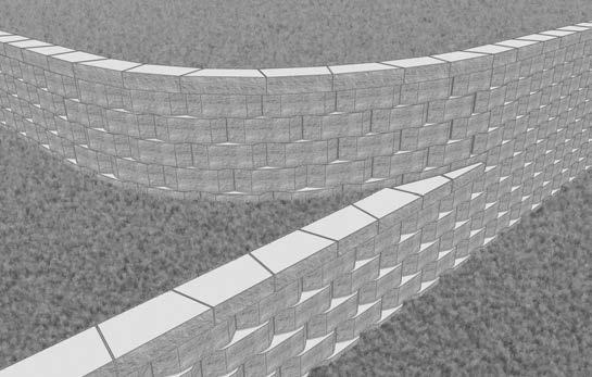
Every project is different. That’s why we offer a wide selection of options for any landscape development. From multiple fascia styles, variable set-backs, unit interchangeability, and the sharpest radius turns, Rockwood® products are designed to give you endless design flexibility.
Our versatile product range also makes it easy to match any existing style or wall type. Whether you’re adding on or starting fresh, Rockwood has an option that’s perfect for your project. So bring your imagination, you’ll be happy you did.
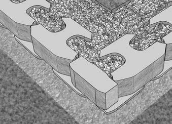
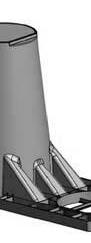
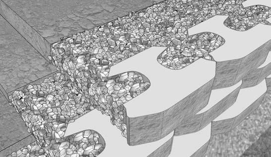
Where’s the Connection? Pins and clips sound good in theory, but many times they are left out due to clogged holes or oversight. Rockwood’s connection is built in, due to the integral Anchor Bar, ensuring proper alignment and precise set-back. Plus, vertical Stone Columns are a fundamental aspect of the Rockwood system. Filled with jagged stone, the Stone Columns unify the grid, backfill, and Rockwood units into one integrated structural design.
It’s no wonder Rockwood has the highest block to block shear strength in the industry.
“One Unit” construction is a central element of Rockwood’s superior design – no special units are required (corners, half block, etc.), no special inventories are needed, and no shortages occur on jobsites. Plus, the unique shape of Rockwood products provides more square feet per pound, reducing shipping costs and making handling easy.
Ease of installation, eliminating guesswork, and reducing labor costs are all benefits of the Rockwood system.
about quality, innovative thinking, and meticulous attention to detail. It’s about being better than you have to be and better than expected. It’s about appearance, dependability, and efficiency.
There is a significant difference in the planning and construction of retaining walls depending on their purpose. Typically walls under 4' in height are referred to as “non-critical” wall structures. Depending on the local, state and municipality requirements, walls under 4' in height may not require special review or permitting. Walls taller than 4' or any wall with a surcharge loading behind it (ie. sidewalk, driveway, building structure) should be evaluated by a qualified engineer.
Zoning
Before you plan your project, learn about the necessary zoning requirements and rules for excavating and building in your area. No matter how small your project, be sure you obtain the necessary permits before you start construction.
Know What’s Below!
Whether you are planning to do it yourself or hire a professional, smart digging means calling 811 before each job. Homeowners often make risky assumptions about whether or not they should get their utility lines marked, but every digging job requires a call – even small projects like planting trees and shrubs.
Use the following methods to estimate the amount of base material, drainage rock, and adhesive you will need for your project.
1. Base Material Needed
A typical trench is 2' wide and 14" deep to bury a full course of 8" block. Your base material must be a minimum of 6" in height.
*Add
for inconsistencies in the trench and compaction.
You need enough drainage rock to fill 1' behind the tail of the block and to fill any cores.
3. Adhesive Needed
The amount of glue required depends on type of block and construction. Use the guide below to estimate the amount of adhesive required.
Approximate length of bead by bead diameter:
Professionals depend on Super-Stik™ adhesive for its superior strength, time-tested performance and versatility. Super-Stik is the ideal solution for segmental retaining walls, pavers, stone and masonry. You can even apply it to damp surfaces!
Especially formulated for:
• Use on damp or frozen surfaces
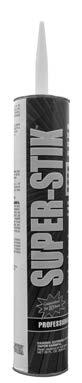
• Superior strength and stability
• Works well in extreme temperatures
• Waterproof bond
The lower profile of Classic® 6 provides a longer and smoother appearance while maintaining all the special features of the Rockwood® Classic family of products. Appealing to homeowners, contractors, and designers, Classic 6 is as flexible as it is versatile. It is capable of sharp radius turns, variable setbacks, and other endless design possibilities. Covering 3/4 square foot per block, Classic 6 makes installation efficient. It can be utilized for various wall applications ranging from the smallest raised patio wall to the most critical wall application.
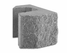
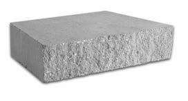
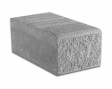
Base Block is used for the first course of a Rockwood wall. With the Anchor Bar removed, the Base Block can be easily set level so successive courses can also be level. Additionally, Base Block can be used as step treads in a stair step application or whenever a level block is needed.
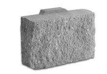
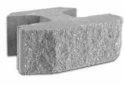
When the wall is stepped, use Half-Block to show a more gradual transition. Half-Block may also be used to abut another structure to maintain a running bond. The split faces provide a more consistent look with the wall face, making it appear more seamless and natural in appearance.
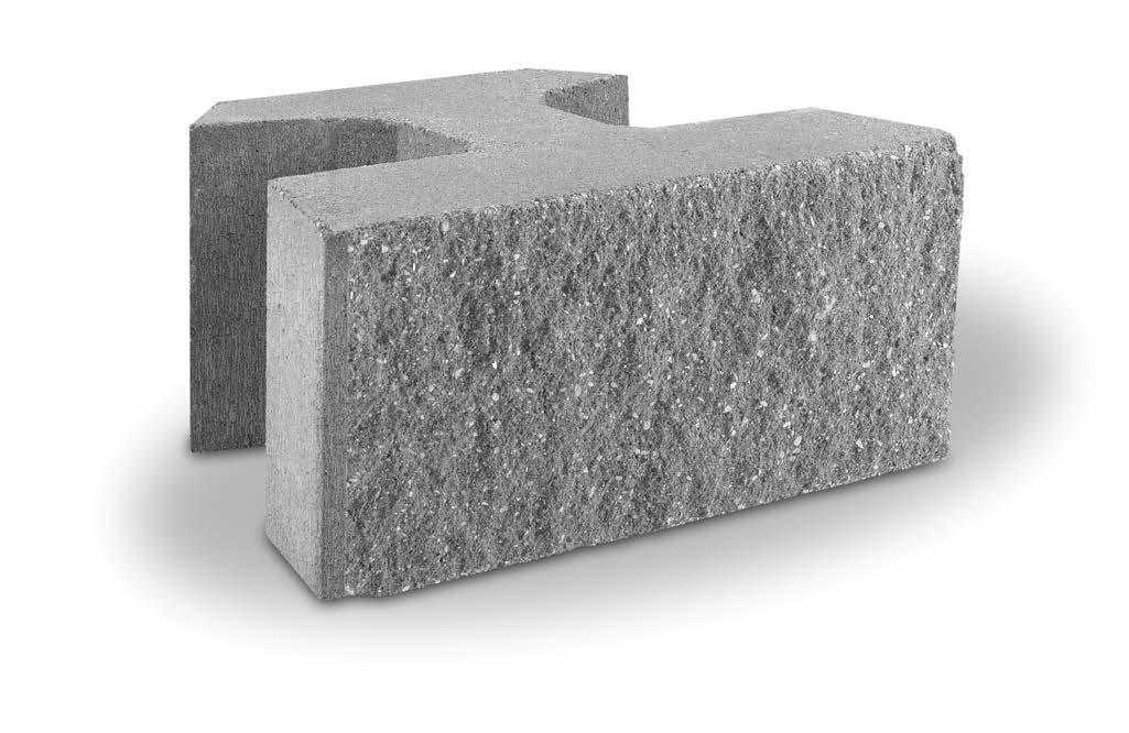
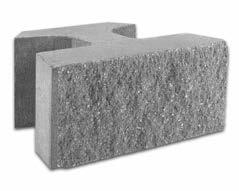
Classic® 8 is a high performance block specifically designed for virtually every retaining wall need. The award winning design is preferred by architects, builders, developers, and engineers worldwide. It is known for its ease of installation, strength, and versatility. Like Classic® 6, Classic 8 is capable of sharp radius turns, variable setbacks, and other endless design possibilities. Covering one square foot per block, Classic 8 offers greater efficiency in installation. Whether the wall is supporting a roadway or being built along the shore of a lake, Classic 8 is a versatile solution for any type of wall application.
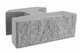
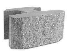
As the name implies, Corner Block can be used for an outside 90° corner. As each course is installed, a Corner Block is positioned alternatively for structural integrity and to maintain a running bond. When stepping a wall, the Corner Block may also be used as an end cap to finish the end of a course in the wall.

Please note: Unit specifications, availability, color, and fascia options vary by manufacturer. Contact your nearest Rockwood manufacturer or dealer for availability and more information.
Designed and manufactured specifically for stair step applications, the Step Tread is a convenient and functional block that can be incorporated in a retaining wall. The rough top surface provides enhanced traction.
The Universal Cap is used to finish the top course of a Rockwood wall. Its flexibility allows it to cap a straight or a curved wall application. It can also be double stacked for stepping a wall or as a step tread in a stair step application.
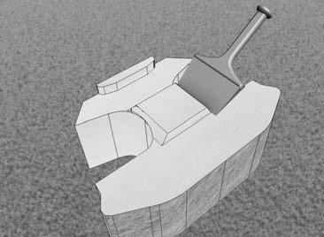
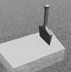
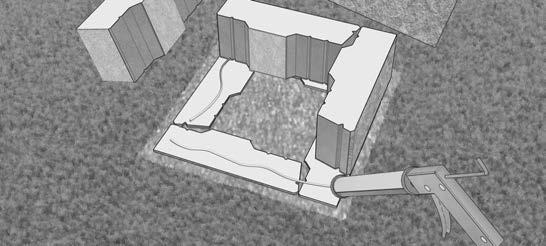
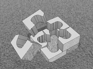
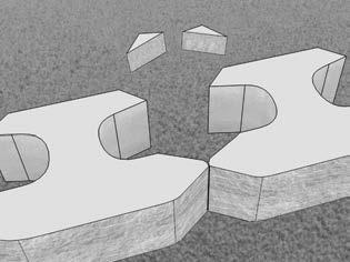
TO CREATE A BASE BLOCK, position the block so the Anchor Bar is facing up. Remove the Anchor Bar with a hammer and chisel as shown – wear protective equipment when modifying the block.
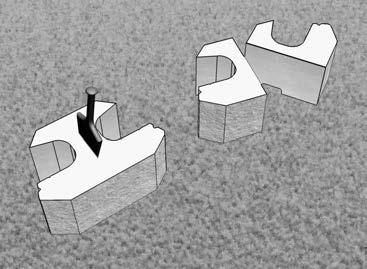
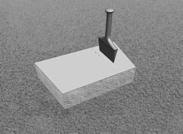
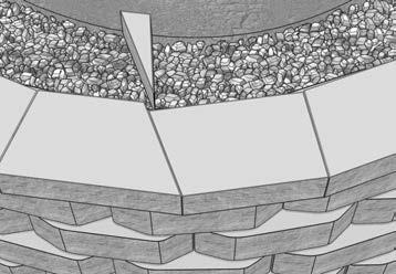
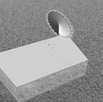
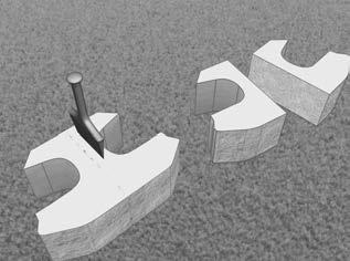
TO CREATE A HALF BLOCK, make a score line in the middle of the block, from front to back and on both sides. Split as shown. Wear protective equipment when splitting.
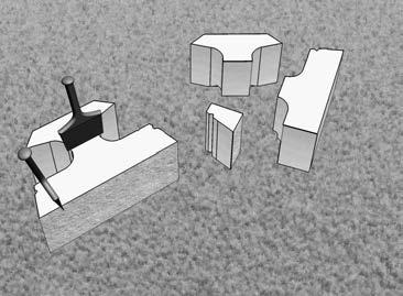
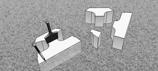
TO CREATE A CORNER BLOCK, make score lines on both splitting grooves and behind the head of the block. Split the block on both top and bottom sides, as shown. A hammer and chisel, or a hand splitter may be used to create the block. Wear protective equipment when splitting.
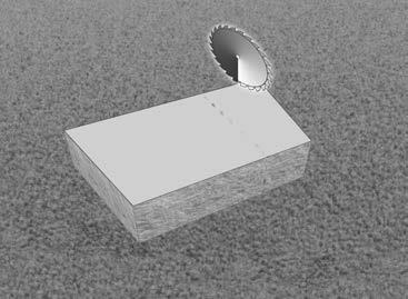
UNIVERSAL CAP can be split with a hammer and chisel for a split finish or cut with a masonry blade for finished accuracy. For a more consistent split, lightly score the Universal Cap on both sides, on a flat and smooth surface. Wear protective equipment when splitting.
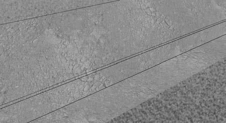
Beginning at a point of the wall’s lowest elevation, excavate a trench down the length of the wall that will accommodate at least 6" of base material and 6" of block embedment. As a rule of thumb, for every 8" to 10" of wall height, 1" of block should be buried with at least a minimum of 6" base course embedment. Step the trench up or down with respect to adjacent grade.
The width of the trench for a Classic® wall should be a minimum of 24", while the trench width for a Legend® wall should be a minimum of 34". Based on the type of application and what is retained, the depth of the leveling pad may vary. If necessary, consult with an engineer.
After excavating the native soil and prior to adding base material, remove loose material from the trench and compact.
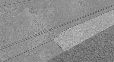
Place and compact a minimum of 6" base material to 95% Standard Proctor. Verify that the base is level with a transit or hand level. Be aware that the base material (commonly referred to as road base or base aggregate) will vary from region to region.
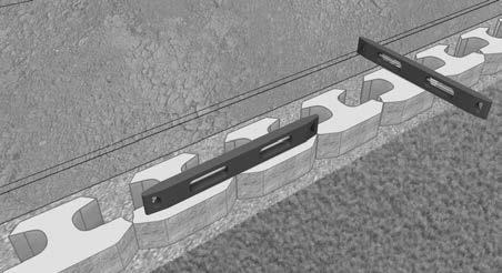
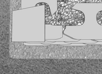
The base course will consist of base block. Use a string line behind the tail of the block for alignment on straight wall applications. All blocks should rest firmly on the pad and be centered to allow 6" of base material in front and 6" behind the Base Block. Level each block, side-to-side, front-to-back and across three full blocks with a hand level. A ded-blow hammer may be used to level and align the blocks.
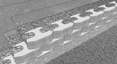
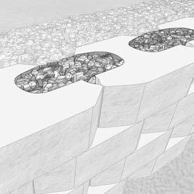
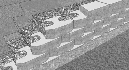
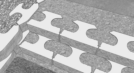
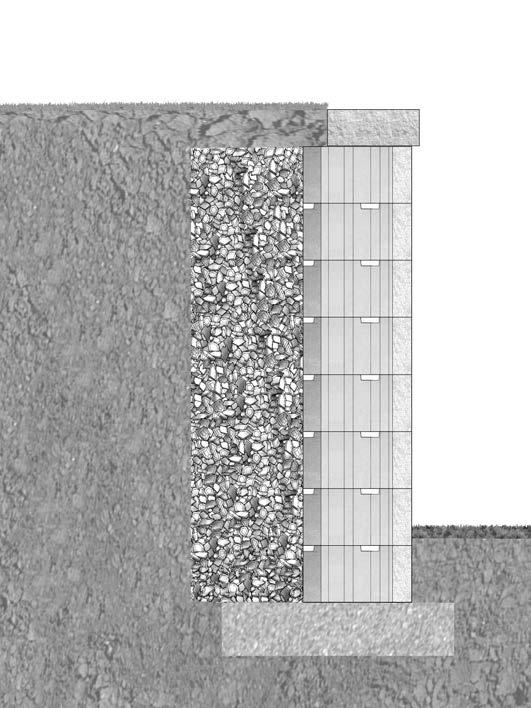
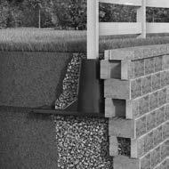
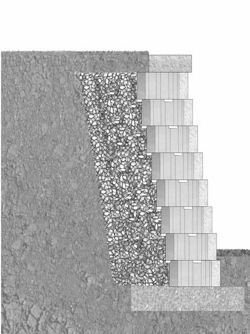
Place 3/4" to 1" clean aggregate (crushed rock) within the cores and a minimum of 12" behind the blocks. This creates a drainage zone and Stone Columns that helps to unify and maximize the performance of the wall.
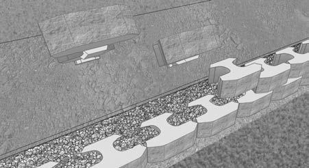
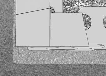
Prior to adding successive courses, the top of each block needs to be clean and free of foreign material. Center the block and pull it forward until the Anchor Bar abuts the two blocks below it. Place core and drainage fill as in Step 4. Place the backfill material behind the drainage rock in maximum of 8" lifts and compact to 95% Standard Proctor. Repeat this process for each successive course.
Large compaction and construction equipment should be kept a minimum of 3' from the back of the wall. This 3' area should be compacted with a vibrating plate compactor.
“Stone Columns” are an integral part of a Rockwood Retaining wall; adding support and stability to the wall.
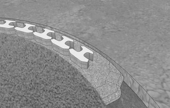
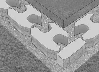
The Universal Cap has both a finished surface and palletized surface. The finished surface should be exposed on the top course to complete the wall application.
The adhesive used for securing cap units should have a high rubber content. Check with your supplier to determine which concrete adhesive is recommended if SuperStik™ adhesive is not available.
To ensure permanent placement of the upper blocks, adhesive should be used.
A Half Block or Corner Block may be used to end a course in a Rockwood application. Double stack 4" tall Universal Caps as an end cap to finish courses of 8" tall blocks.
While the installation steps presented are applicable to most basic wall designs, special consideration needs to be given to those applications in which a slope, surcharge loading, and/or less than ideal soils are present. These types of applications may require geosynthetic reinforcement or other engineering design support. Such applications include, but are not limited to:
• Wall Height
• Tiered Wall
• Driveways and Roads
• Bridges and Culverts
• Fences and Guardrails
• Water Applications
• Drainage
• Structures
Please refer to the geosynthetic reinforcement section for more information in regard to the incorporation of geosynthetic reinforcement in wall design. www.rockwoodwalls.com
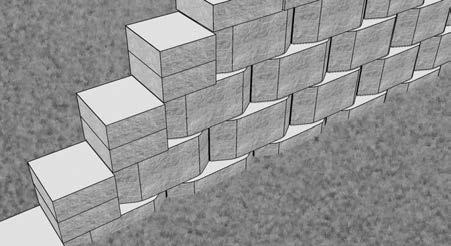
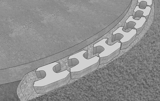
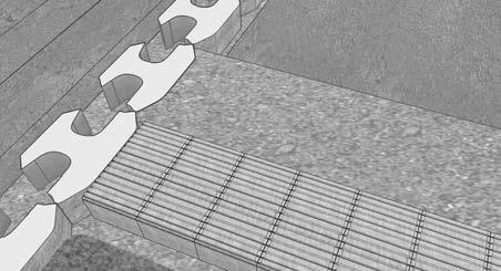
Step 1 - Base Course Preparation for a Convex or Concave Curve
Place the blocks on the leveling pad so there are no gaps between them.
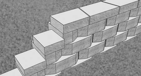
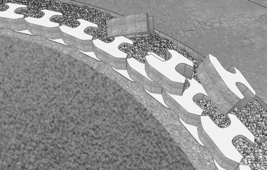
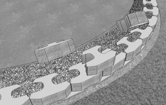
Step 2 - Successive Course Installation for a Convex or Concave Curve
When building multiple courses on a curve, begin installation by placing a block in the middle of the curve and centering it on two blocks directly below it. Build the wall from the center block outward.
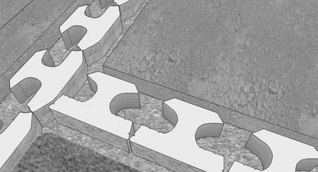
Begin an outside corner from the corner of the wall and install the blocks from the corner out when possible.
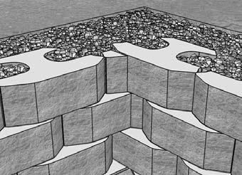
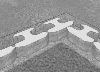
Stagger the Corner Block as each successive course is installed so it is on the opposite side of the wall corner. Length adjustments to the Corner Block may be necessary to maintain a running bond.
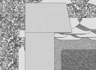
Using a hammer and chisel, score and split a Universal Cap four inches from one side. Position it on the corner with one or two inches of overhang.
Cut another Universal Cap to be placed on the adjacent corner wall so that it is flush with the other cap unit. Adhere Universal Caps with Super-Stik™.
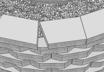
Begin an inside corner from the corner of the wall and install the blocks from the corner out when possible. Only half of a whole block installed on the corner will be exposed. This is true of each successive block that is staggered in the corner.
Gaps will develop in successive courses, which will require a “wedge” block to fill the gap. Measure the gap and cut a block to fill the gap. Adhere cut block with Super-Stik™. Depending on the height of the wall, the “wedge” block will eventually become the same size as a whole block, then the process repeats itself.
Using a hammer and chisel or a masonry saw, cut a Universal Cap so it is perpendicular to the wall face.
Cut the next Universal Cap to be flush with the corner cap. Adhere Universal Caps with SuperStik™.
The installation described below using Rockwood’s Classic® 6 and Universal Caps is for a basic stair step application. It is recommended the riser width be considered in 18" increments for this particular application. This will ensure full blocks fit the width of the stair steps without having to cut them, since each block is 18" in width. Beveled blocks may be used for this application, but straight face blocks offer a more uniform and straight finish.
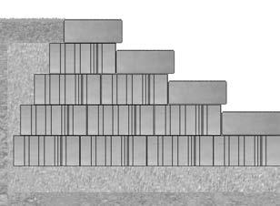
The step rise is 6". The step depth is 10". To determine the number of risers needed, divide the height of the stair by the riser height. To determine the length of the side stair walls, multiply the depth by the number of risers.
Follow the standard procedures for base course installation and place the blocks on the leveling pad so there are no gaps between them.
Excavate for a minimum of 6" of base material under all risers. Proper compaction to 95% Standard Proctor is crucial in a stair step application. Each successive riser should overlap the previous riser by 2". Fill the cores and backfill behind the wall with the base material to 95% Standard Proctor. Repeat this process for each successive riser. The side stair walls must be vertical with no setback.
When capping risers, make sure the top of the risers are swept free of any foreign material.
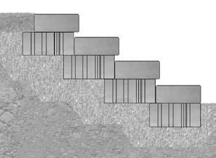
The installation described below uses Rockwood’s Step Treads and is for a basic stair step application. It is recommended the riser width be considered in 8" increments for this particular application. This will ensure full blocks fit the width of the stair steps without having to cut them, since each block is 8" in width.
The step rise is 6". The step depth may vary from 10" to 13". To determine the number of risers needed, divide the height of the stair by the riser height. To determine the length of the side stair walls, multiply the depth by the number of risers.
Follow the standard procedures for base course installation and place the blocks on the leveling pad so there are no gaps between them.
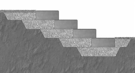
Excavate for a minimum of 6" of base material under all Step Treads. Allow for the base material to extend a minimum of 18" behind each successive course of Step Treads. Proper compaction to 95% Standard Proctor is crucial in a stair step application. Each successive Step Tread should overlap the previous riser by 2" to 5". Repeat this process for each successive riser. The side stair walls must be vertical with no setback.
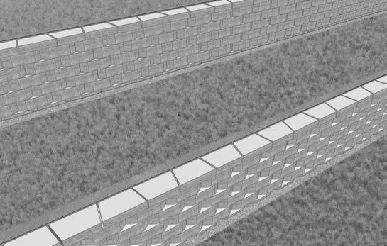
Branched walls require a minimum of one course embedment, as if each wall is independent. Tiered walls may be installed where it is desirable or aesthetically pleasing to use more than one wall. Upper walls can exert surcharge loads on lower walls. In order to design tiered walls independently, the walls must be set back a distance of at least twice the height of the lower walls. Whenever tiered walls are constructed, a qualified soils engineer should be consulted.
Your distributor may carry Corner Blocks. If you need to create corners on the job site, see instructions on page 7 on how to create Corner Blocks.
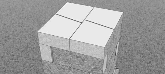
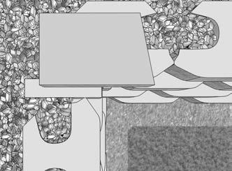
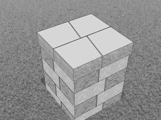
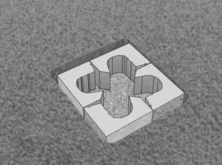
Follow the steps for a leveling pad installation, as described in basic wall installation. Lay the first four pillar blocks with the split faces exposed to create the foundation for the 20" Pillar.
Stagger the pillar blocks so a running bond is maintained. Adhere all blocks with Super-Stik™.
A 20" Pillar may be capped with Universal Caps, stone, or other prefabricated products. Adhere caps with Super-Stik™.
Rockwood’s blocks offer the unique ability to modify the facing batter of a wall. This is especially useful in stair step and egress window applications. For 6" tall Blocks, adjust setback by 3/4". For 8" tall Blocks, adjust setback by 1". The setback is determined by how much material is removed.
To adjust the setback, modify the two blocks below the successive course by splitting at the grooves on the top of each block.
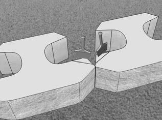
NEVER ALTER THE ANCHOR BAR! Doing so will adversely affect the performance of the wall.
Your distributor may carry Half-Blocks. If you need to create Half Blocks on the job site, be sure you have Base Block.
Follow the steps for a leveling pad installation, as described in basic wall installation. Lay the first four Half-Blocks with the split faces exposed to create the foundation for the HalfBlock Pillar.
Stagger the Half-Blocks so a running bond is maintained. Adhere all blocks with Super-Stik™.
A Half-Block Pillar may be capped with Universal Caps, stone or other prefabricated products. Adhere caps with Super-Stik™.
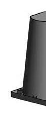
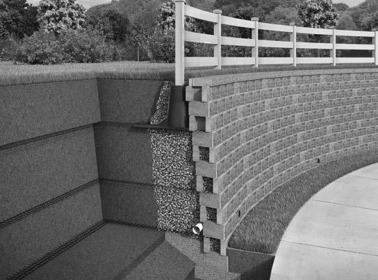
Special consideration must be taken when designing a retaining walls that includes fence or guardrail posts.

Sleeve-ItTM is a proven system that uses a traditional cantilever design to engage the overlying soil mass, thereby providing resistance to the fence load. Sleeves should be installed as the wall is constructed. In reinforced walls, geogrid will need to be cut to fit around the Sleeve-It . Consult with an engineer in regard to design and application. For complete details, visit: www.geogrid.com/sleeve-it.html

Retaining walls constructed along or around retention ponds, shorelines, and other bodies of water require special consideration. Design considerations include drainage, foundation strength, erosion or scouring at the base of the wall, freeze thaw, and hydrostatic pressure.
The diagram shown is a typical section illustrating components that may be required in a water application. It should not be used or interpreted as a design section for water applications. Consult a qualified engineer for site specific requirements in all shoreline and water applications.
Geosynthetic reinforcement is an engineered product that is typically comprised of polypropylene, polyester, or other high tensile material. Used in conjunction with segmental retaining wall blocks, it helps stabilize the soil mass behind a wall. Depending on the wall design, the length and the number of grid layers will vary.
Generally, grid strength is in the roll direction. As it is unrolled, it is in the same direction it should be installed. Biaxial grid is another option in which the strength is the same against roll direction as it is in the roll direction.
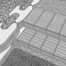
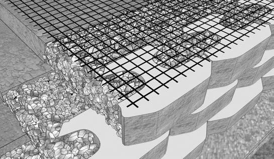
Place the grid as close to the face of the wall without exposing it after successive placement of blocks. Ensure the grid is placed with the strength direction perpendicular to the wall. Check grid manufacturer specifications for proper grid placement instructions.
Place the next course of block. Pull the grid back and stake it so it is taut and free of wrinkles.
The area behind the wall on the grid layer needs to be level with the top of the block and to 95% of the Standard Proctor (ASTM D698).
Place 3/4" to 1" clean aggregate (crushed rock) within the cores and a minimum of 12" behind the blocks. Place and compact backfill on the grid in lifts no greater than 8". When possible, it is recommended the backfill is deposited directly behind the wall and pushed to the end of the grid to ensure it remains taut and wrinkle-free.
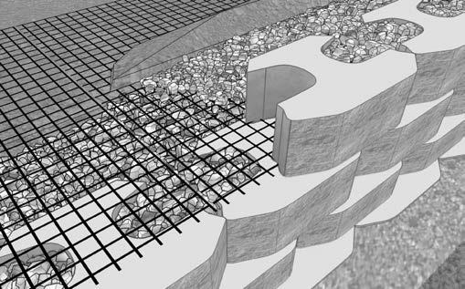
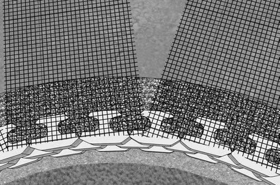
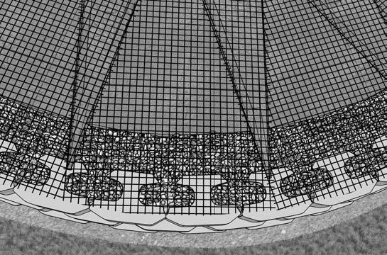
Place grid following the contour of the curve.
Overlapping layers of grid on a convex curve require a minimum of 3" of fill between them for proper anchorage. Repeat these steps for successive specified grid layers.
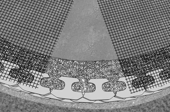
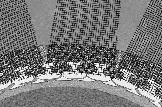
Making sure the strength direction of the grid is perpendicular to the wall face, align the cut grid sections so they follow the contour of the concave curve. Grid layers should not overlap. An engineer will specify grid lengths.
After the next course of block is placed, lay the grid to cover the area of unreinforced soil below. This will ensure 100% coverage. Repeat these steps for successive specified grid layers.
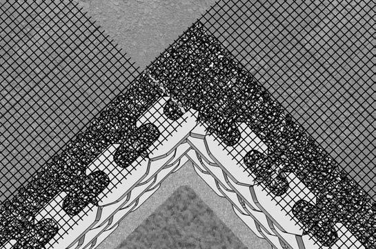
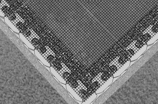
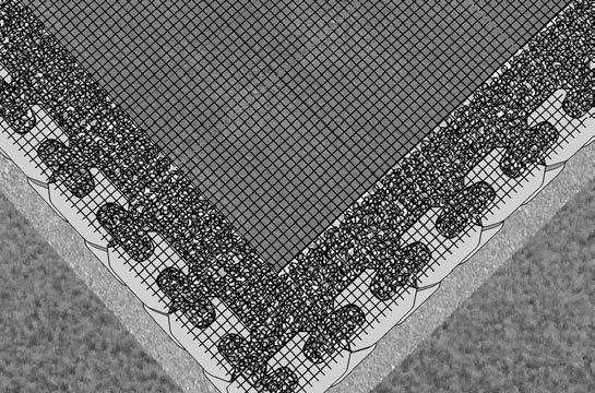
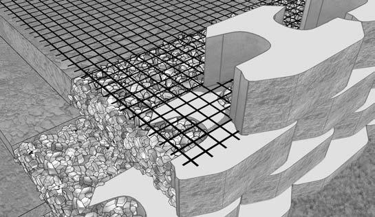
On an outside 90° corner, it is important that grid layers do not overlap at the corner. Place the first grid layer per plan at its design elevation and length.
Extend the grid past one edge of the wall by a minimum of 2'. Along the other edge, place the grid to the corner.
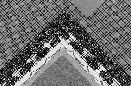
In the corner and on the next course of blocks, place a layer of grid perpendicular to the previous layer of grid. Repeat these steps for successive specified grid layers.
At the next designed grid layer, alternate the edge on which the grid is extended past the corner. Repeat these steps for successive specified grid layers.
The above design tables were determined using the following assumed soil parameters and conditions:
for all soil types.
The above design tables were determined using the following assumed soil parameters and conditions:
3' Wall (6 Courses)
4' Wall (8 Courses)
5' Wall (10 Courses)
6' Wall (12 Courses)
7' Wall (14 Courses)
8' Wall (16 Courses)
The above design tables were determined using the following assumed soil parameters and conditions: Unit weight (γ)=120pcf for all soil types.
assume a
compacted angular aggregate base (road base) leveling pad and swale directly behind wall.
design charts are for preliminary use only. A final site specific design should be evaluated and approved by a qualified professional engineer. For positive connection grid tables, consult a qualified professional engineer.
The above design tables were determined using the following assumed soil parameters and conditions:
weight (
)=120pcf for all soil types.
for preliminary use only. A final site specific design should be evaluated and approved by a qualified professional engineer. For positive connection grid tables, consult a qualified professional engineer.
The above design tables were determined using the following assumed soil parameters and conditions: Unit weight (γ)=120pcf for all soil types.
design
are for preliminary use only. A final site specific design should be evaluated and approved by a qualified professional engineer. For positive connection grid tables, consult a qualified professional engineer.
The above design tables were determined using the following assumed soil parameters and conditions: Unit weight (γ)=120pcf for all soil types.
angular aggregate base
leveling pad and swale directly behind wall.
design charts are for preliminary use only. A final site specific design should be evaluated and approved by a qualified professional engineer. For positive connection grid tables, consult a qualified professional engineer.
What is the Anchor Bar?
The Anchor Bar is a 4" x 4" x 5/8" projection on the bottom of the block that is laid against the backside of the face of the two blocks below.
What is backfill?
Backfill is the material placed behind the drainage zone that has been removed and replaced during the construction process. It needs to be compacted back to 95% Standard Proctor.
What is the base material?
The leveling material used to distribute the weight of the blocks over a wider foundation and to provide a working surface during construction. Base materials are composed of coarse-grained material ranging in size from fine sand to 1" aggregate.
What is batter?
Batter is the angle at which the face of the wall is from being vertical.
What is clay?
Clay is a fine-grained soil that typically possesses both plasticity and cohesiveness. It is considered a poor soil for construction purposes.
What is compaction?
Compaction is the densification of soils by means of mechanical action with equipment such as a plate compactor, jumping jack or hand tamper. Compaction is the most fundamental element in wall construction.
What is drain tile?
Drain tile is perforated pipe placed in the backfill and used to transport water away from the wall. Drain tiles are typically 4" perforated PVC pipe.
What is a drainage zone?
The drainage zone helps alleviate hydrostatic pressure at the back of the block. 3/4" to 1" clean fill (crushed rock) is placed a minimum of 12" directly behind the blocks.
What is an expansion joint?
An expansion joint is a space which allows for expansion as to not adversely effect an adjacent structure.
What are fines?
Fines are fine-grained soils, such as clay or silt.
What is Friction Angle?
It is an angle that describes the rate at which a soils’ strength increases under loading. The greater the friction angle of a soil, the lesser the lateral loads on a wall.
What is geosynthetic reinforcement?
Typically known as geogrid, it is a high tensile polypropylene or polyester material that helps stabilize the soil mass behind the wall. The number of grid layers and grid lengths are determined by a number of variables; including wall height, type of soil, etc.
What is filter fabric?
It is a geotextile used to filter fines from water. It is commonly placed between the topsoil and the backfill and drainage zones to eliminate the migration of soils into the drainage zone and to help prevent wall face staining.
What is grade?
Grade is considered to be ground level.
What is a gravity wall?
A gravity wall is able to resist soil pressure by relying only on its mass. This type of wall does not require geosynthetic reinforcement.
What is hydrostatic pressure?
It is the pressure exerted on the back of a wall by water in undrained or saturated soils.
What is a leveling pad?
The level surface (gravel or concrete) used to distribute the weight of the stacked blocks over a wider foundation area and to provide a working surface during construction. The leveling pad is typically constructed with granular soil to facilitate compaction.
What is retained soil?
It is the soil, excluding backfill, which is retained by the wall.
What is silt?
Silt is a fine-grained soil.
What is a Stone Column?
It is a continuous vertical column of clean fill material that is formed when the Rockwood block cores are filled. The Stone Column unifies grid and block into an integrated structural system.
What is surcharge loading?
It is a force exerted at the top of wall such as loading from a slope, roadway, parking lot, or building. Surcharge loading should be considered in the design of a wall.
What is a swale?
A ditch or canal used to divert water away from the back of the wall.
Be sure you have Rockwood’s engineers create a Prelim (Preliminary Material Quantity Take-off) before you bid commercial wall projects. Project Prelims using Rockwood products are done at no charge.
For engineering assistance, contact your regional Rockwood sales representative or call (507) 529-2871.