folio

DEEPAK AGRAWAL Port

CONTENTS 01 02 03 04 05 06 07 08 09 10 11 04 14 22 30 36 42 52 58 64 70 74 The Metropolis of Tomorrow The Section House New Atlanta Central Library Urban Complexities Design Detail, Atlanta Library Transformed, Fondation Louis Vuitton The Sexy Chair LA/G WRP Personnel Buildings Incremental Housing ‘Pay as you go’ The Courtyard House Heritage walk, Hussainabad © 2020 All rights reserved. No part of this book maybe reproduced in any form without permission of copyright owner. Deepak Agrawal deepak225@gmail.com
THE METROPOLIS OF TOMORROW
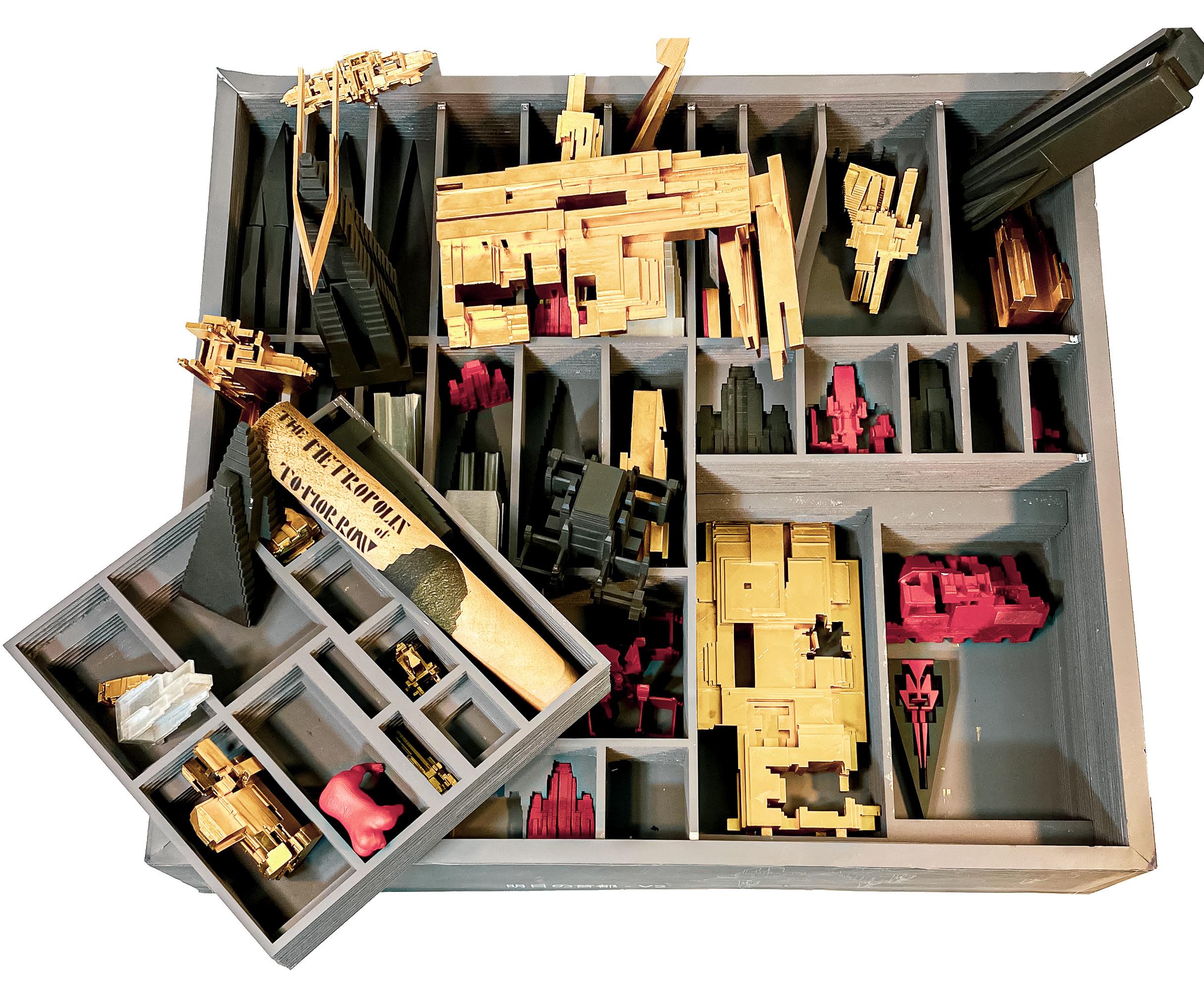
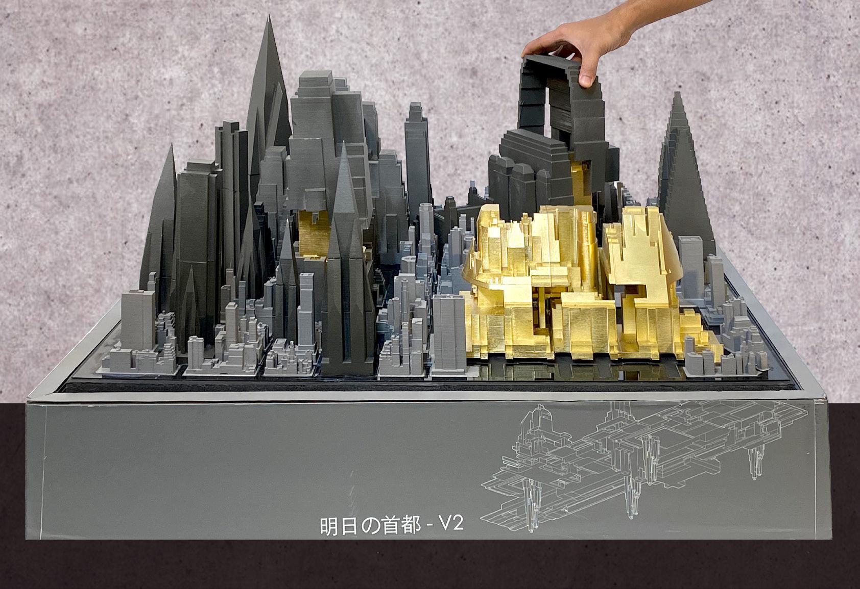
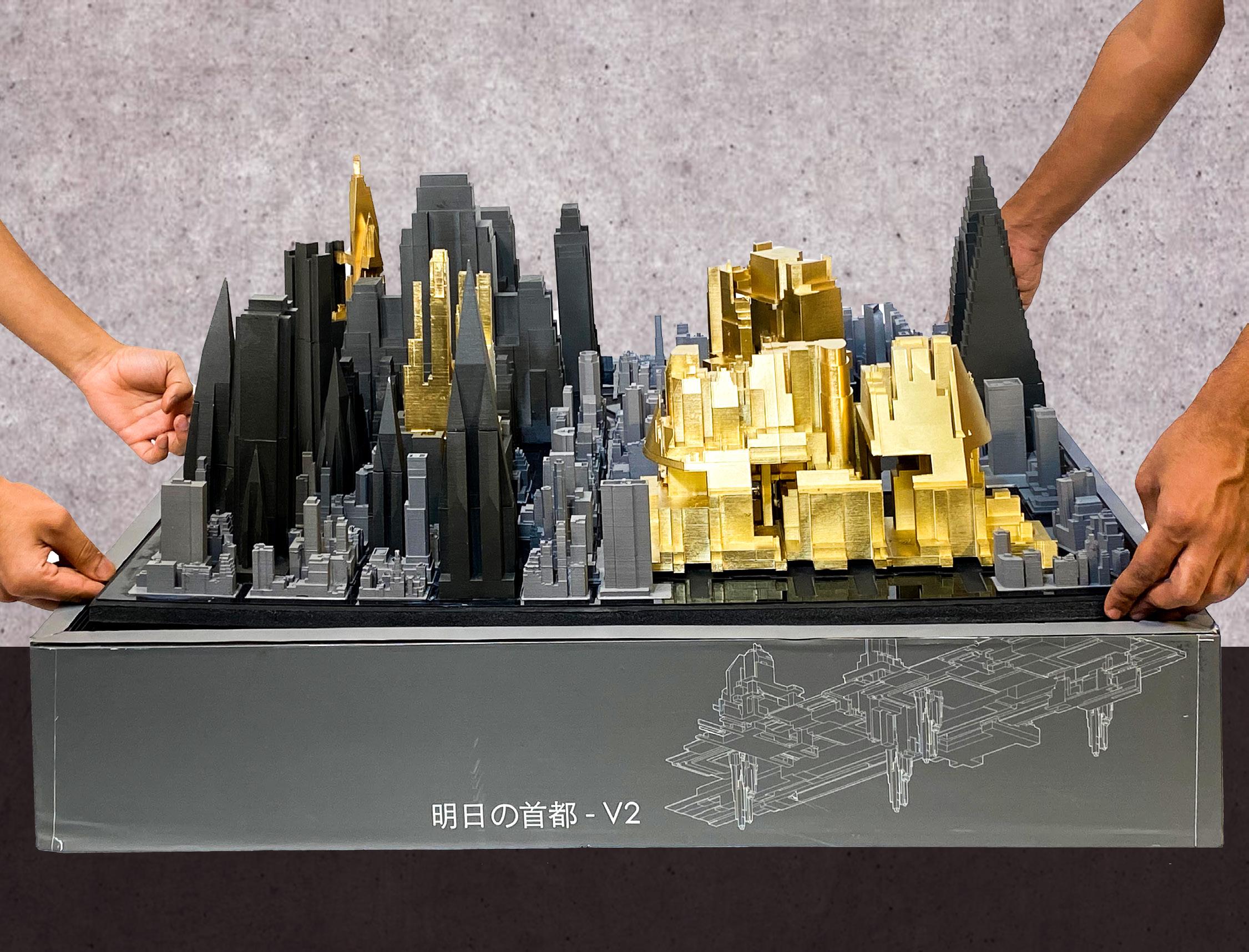
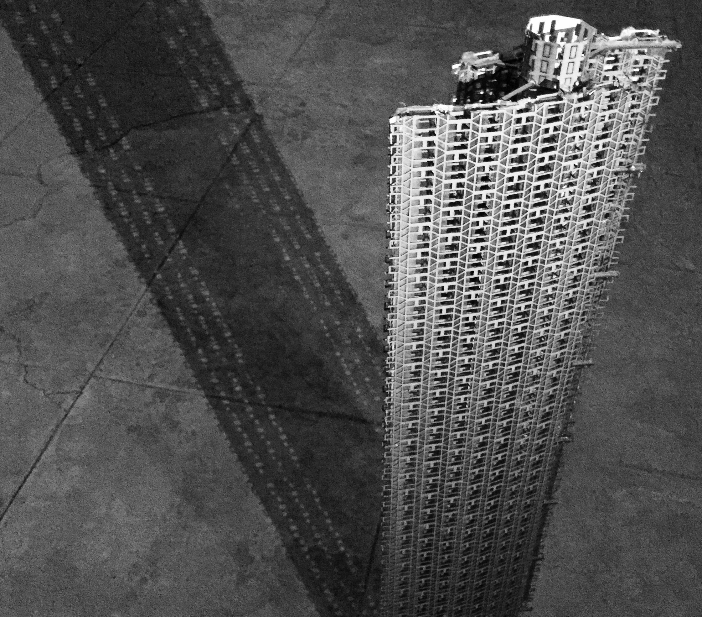
Model kits from outside architecture are a special kind of model. They have the dual quality of both -being kits pf parts that make a ‘scale’ model, but the ‘set’ is also crucial to the overall understanding of the thing.
The design project is to make a model as an end product to use it as a method for producing architecture. It focuses on the strange scale effects that are germane to models,and project these into everyday reality in a variety of ways. Strange scales, mixed resolution, toy-like qualities and strange componentry comes into play as the project develops into a real-scale building design.
4
01 5
SCI-Arc | Spring 2020 Instructor : Tom Wiscombe
DESIGN PROCESS |
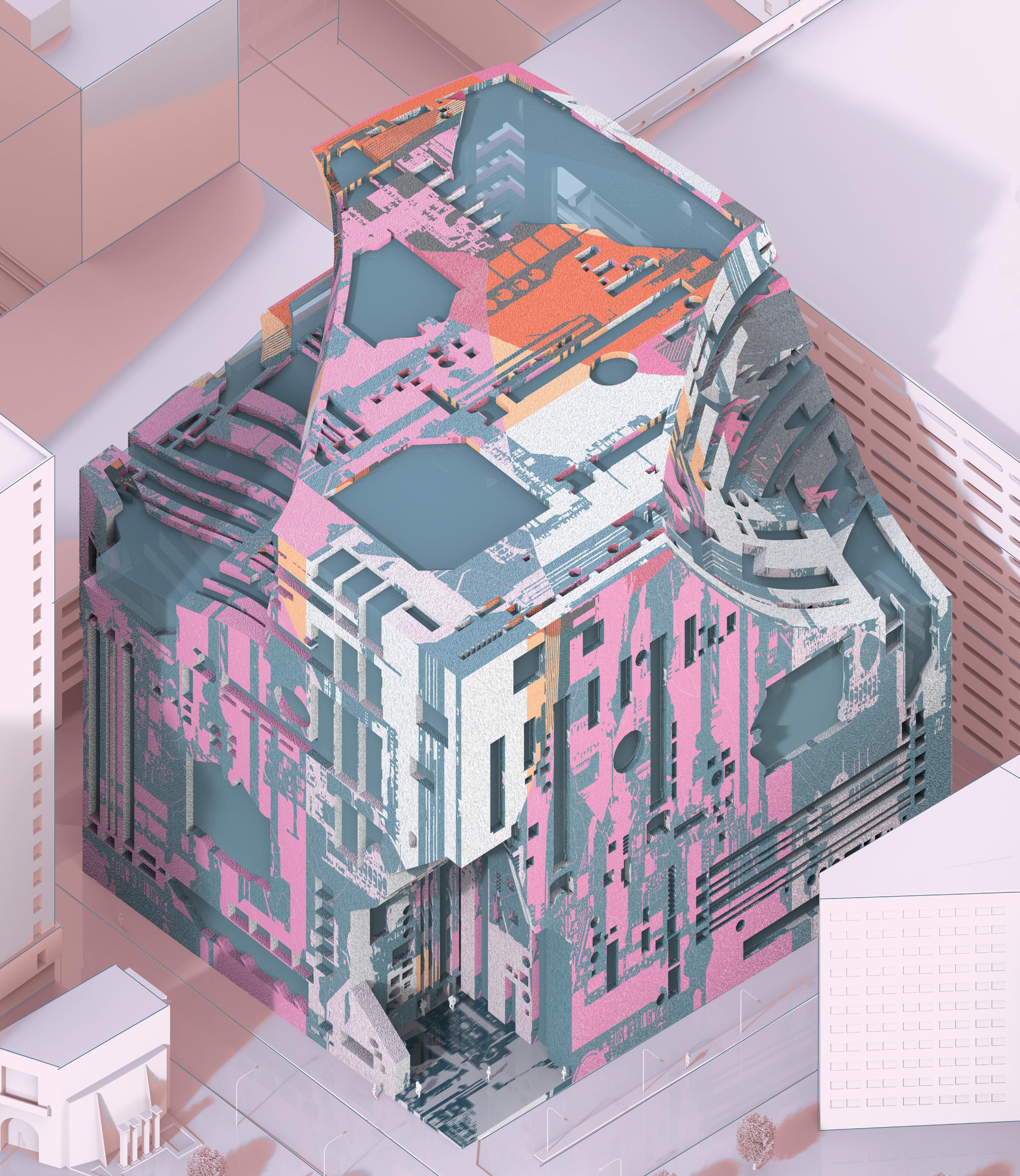
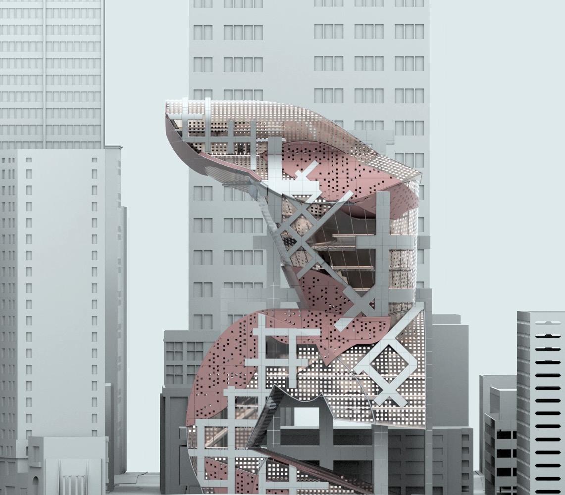
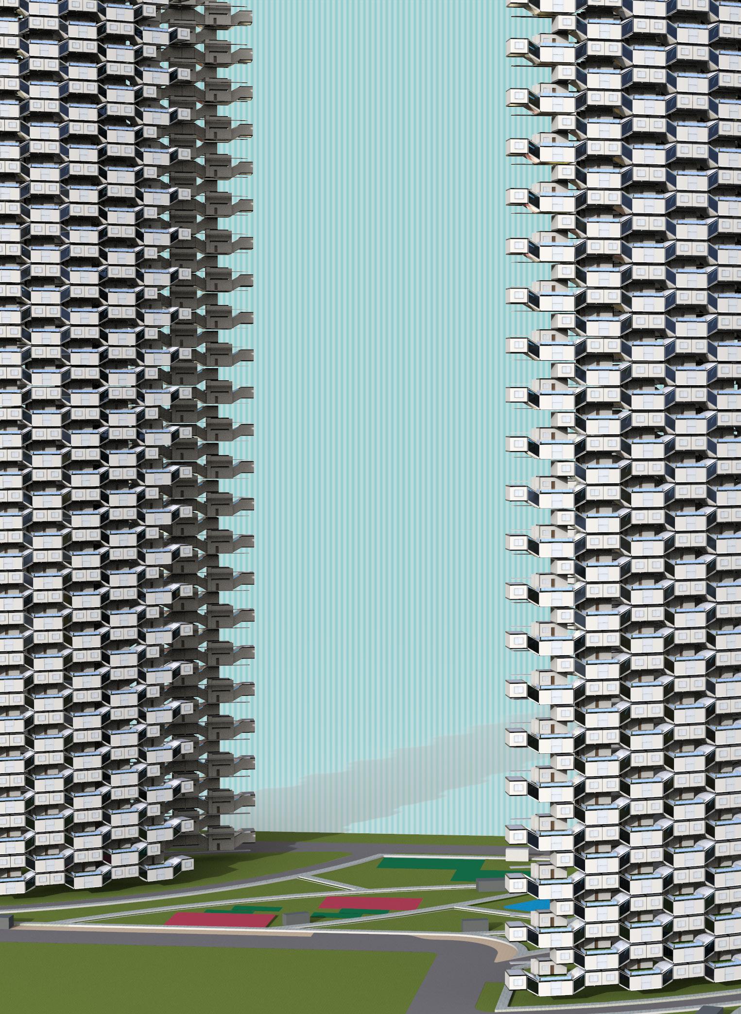
The project is inspired from Hugh Ferris’ sketches and his imagination of an ideal city of the future with skyscrapers placed well apart from each other, broad avenues and a coherent organization of building typologies.
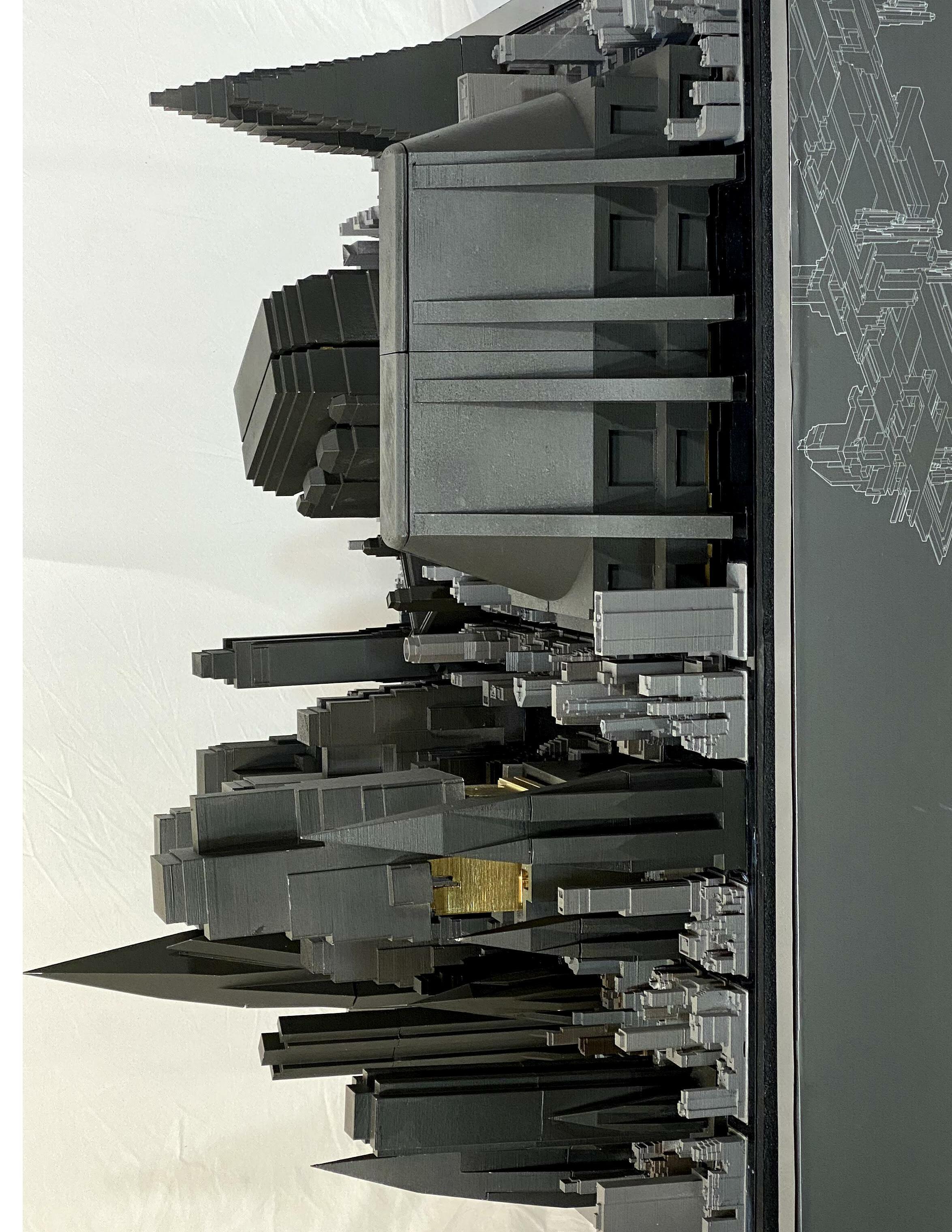
The alternate version of the mega-city is imagining Hugh Ferris’s buildings as a compressed version or a mat. The voids created make room for adding parts to form a new scheme for interiors.
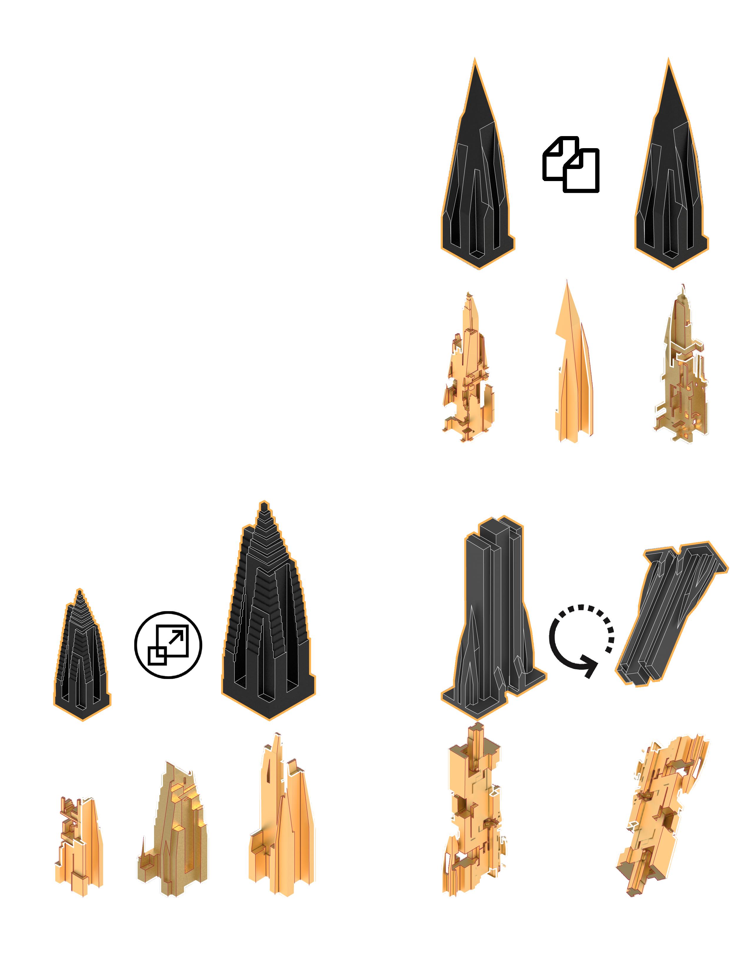
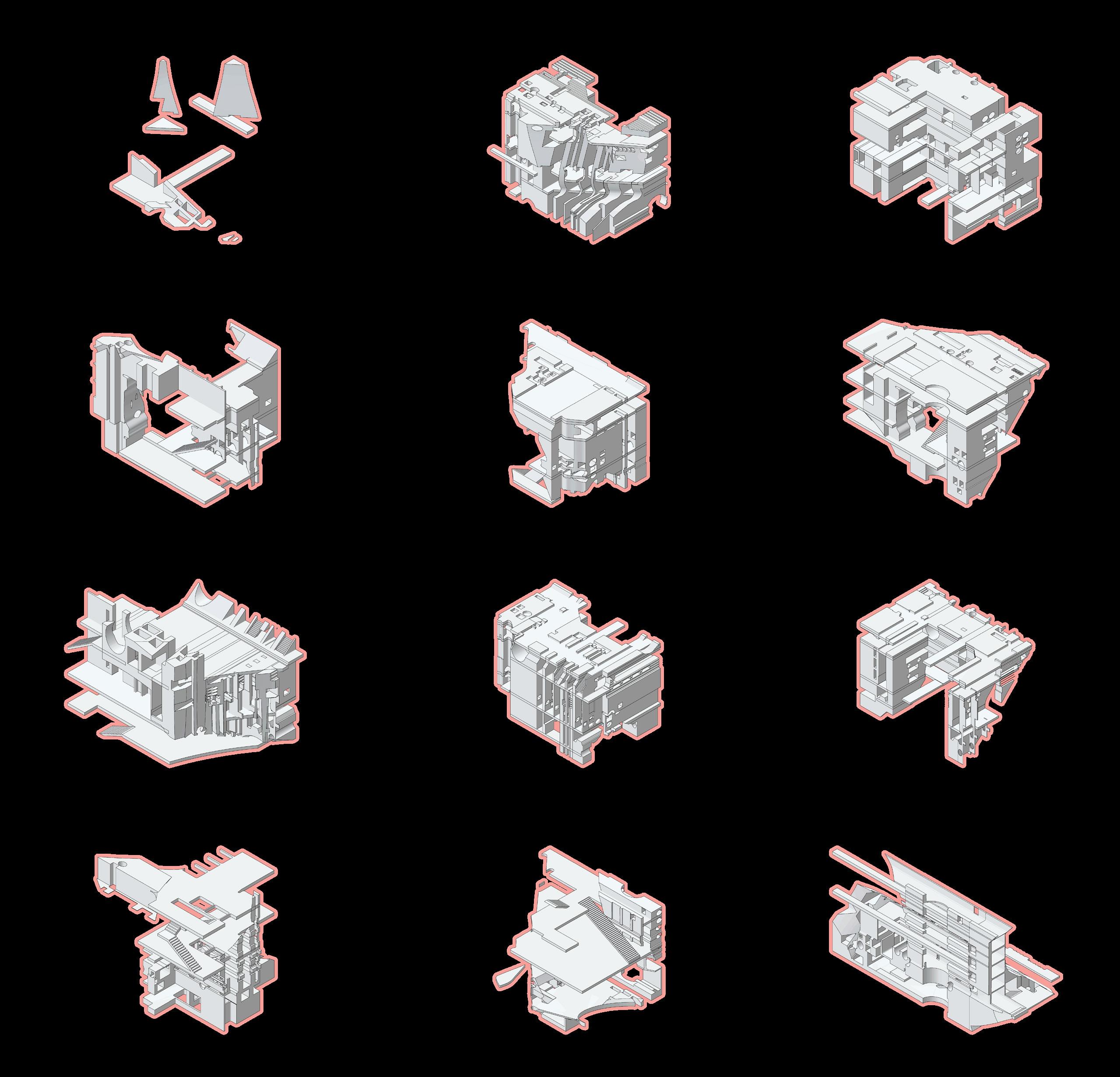
Special care is given to the orientation, scale and detail of parts in the kit, with tricks like duplication of parts, spare parts, missing parts and multiple scales to activate a ‘curated’ collection of things.
THE TOY KIT |
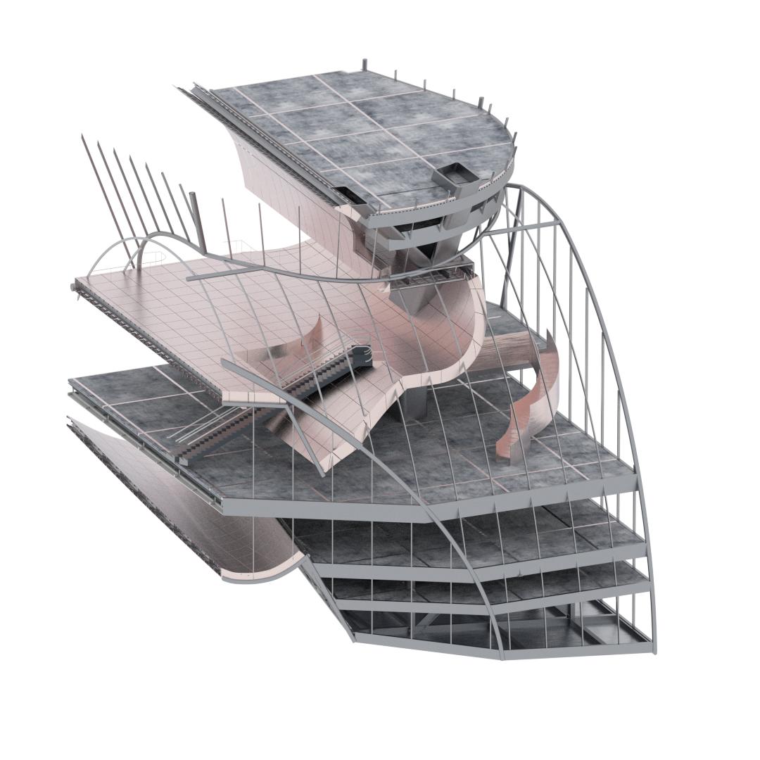
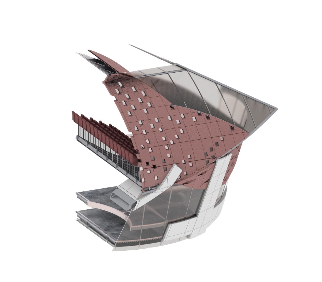
Parts of the model are designed and detailed in ways that makes them lively and alien. The kit can be seen as a hyper-object which is not built from the precedent study at all but rather suggests an alternate, unfamiliar reality.
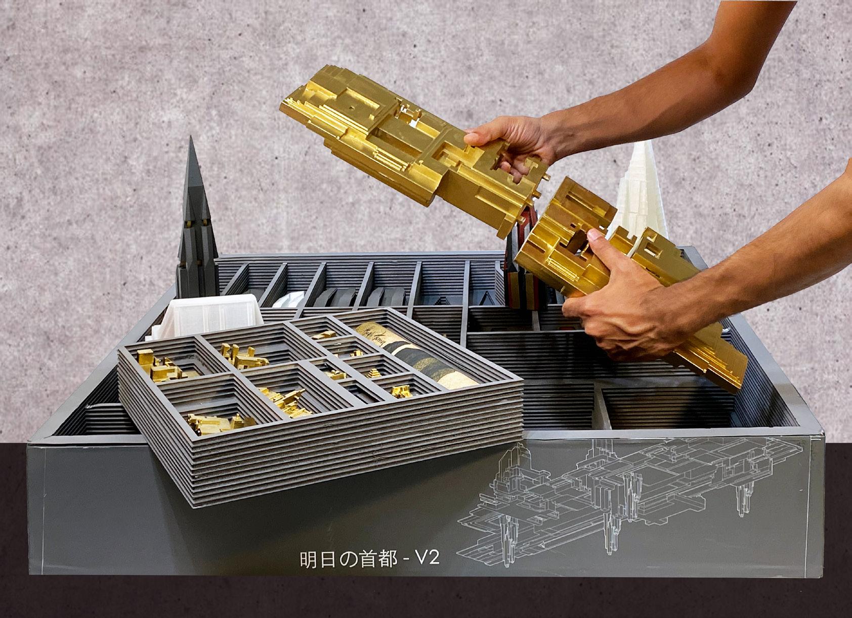
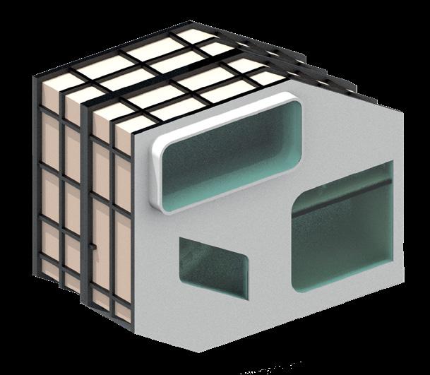
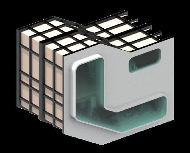
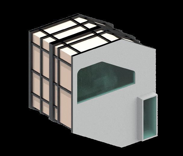
The mega-city model is generated like series of cities enclosed in box. This proposal seeks to imagine this city as a toy where the building parts click and lock to assemble or disassemble to showcase the dual characteristics of the building.
8 9
10 11 | GODZILLA DRAWING
OBM HEADQUARTERS |
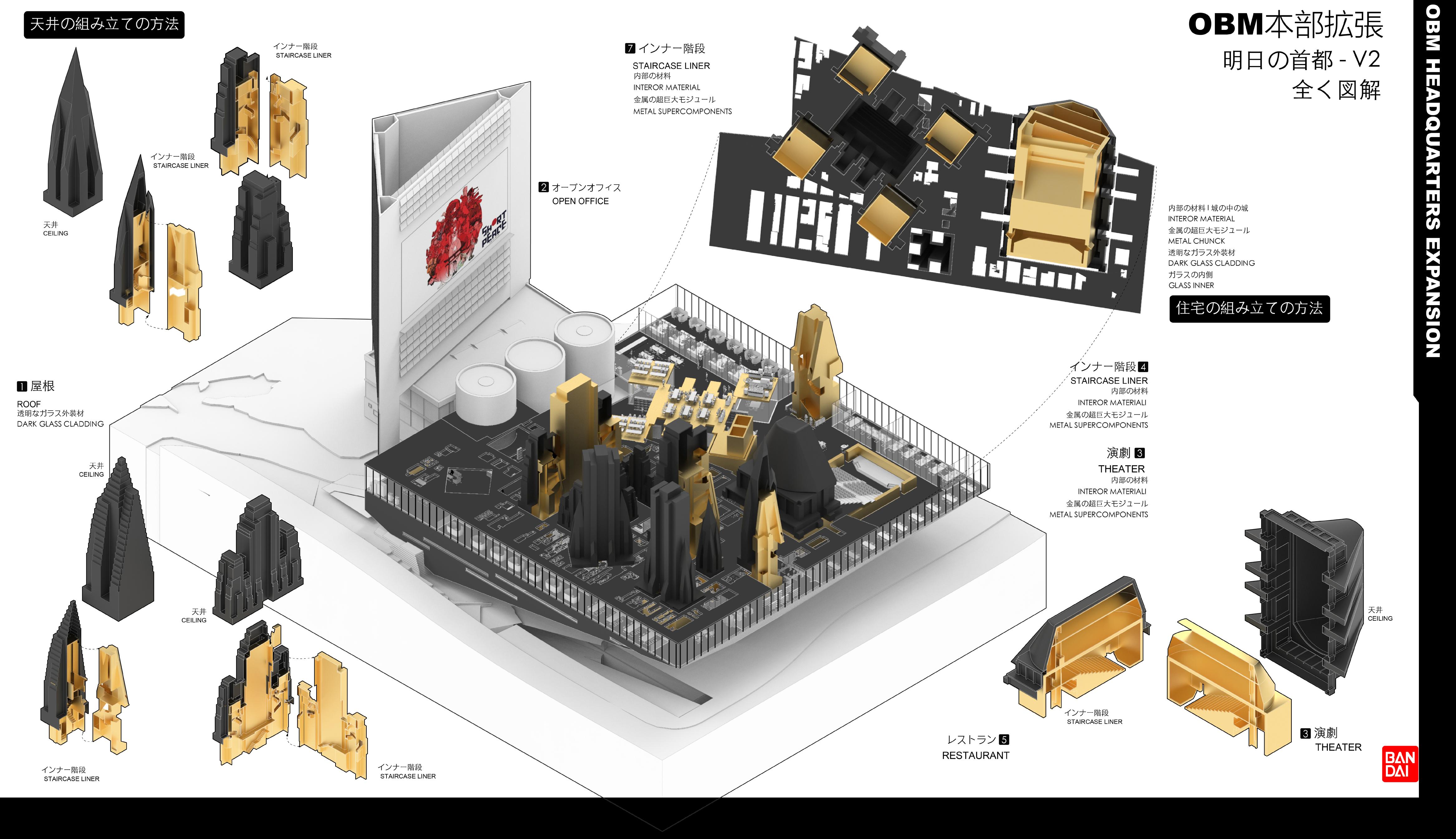
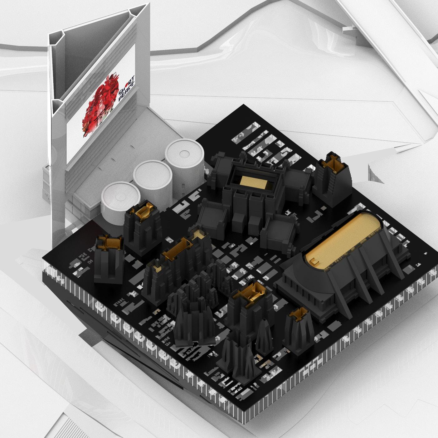
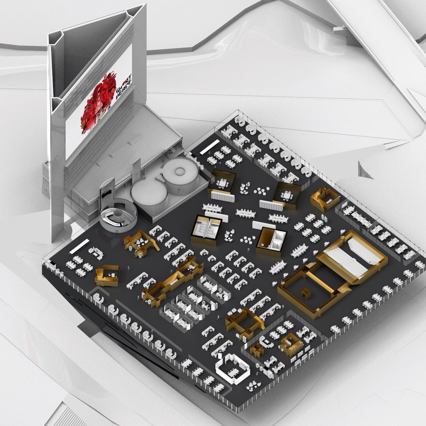
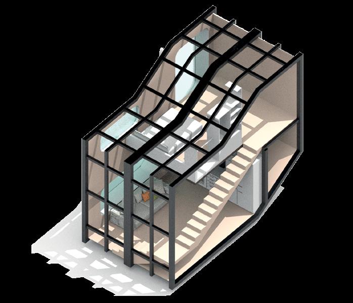
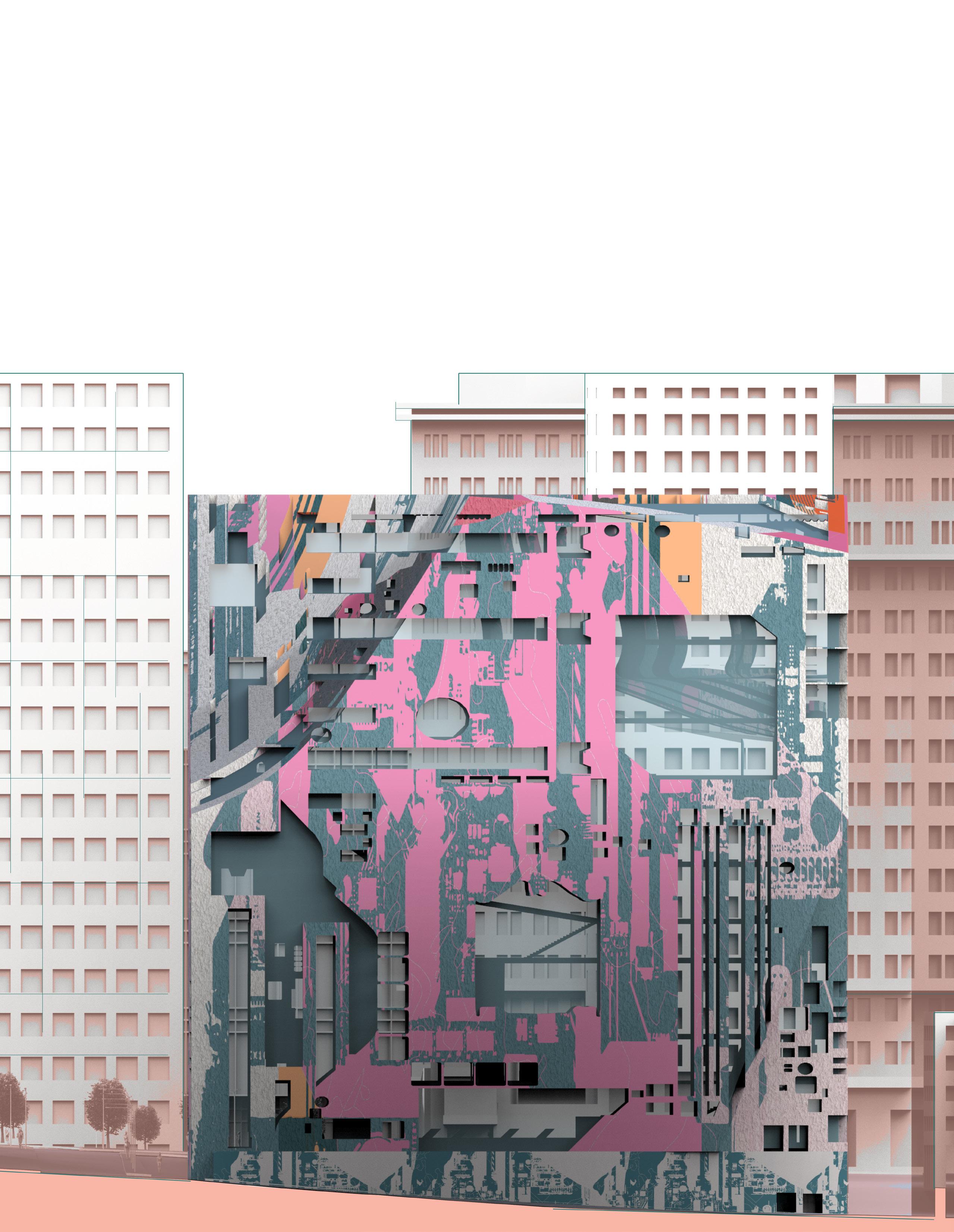
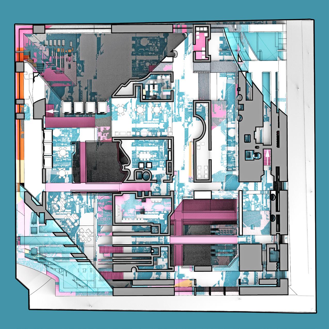
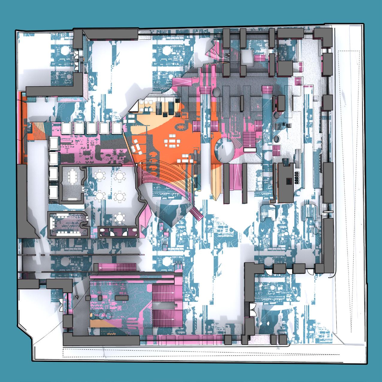
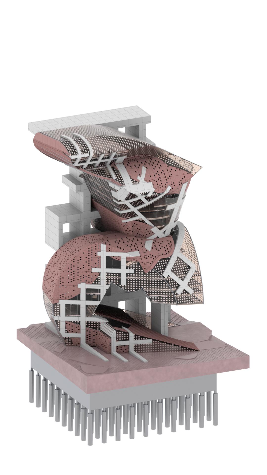
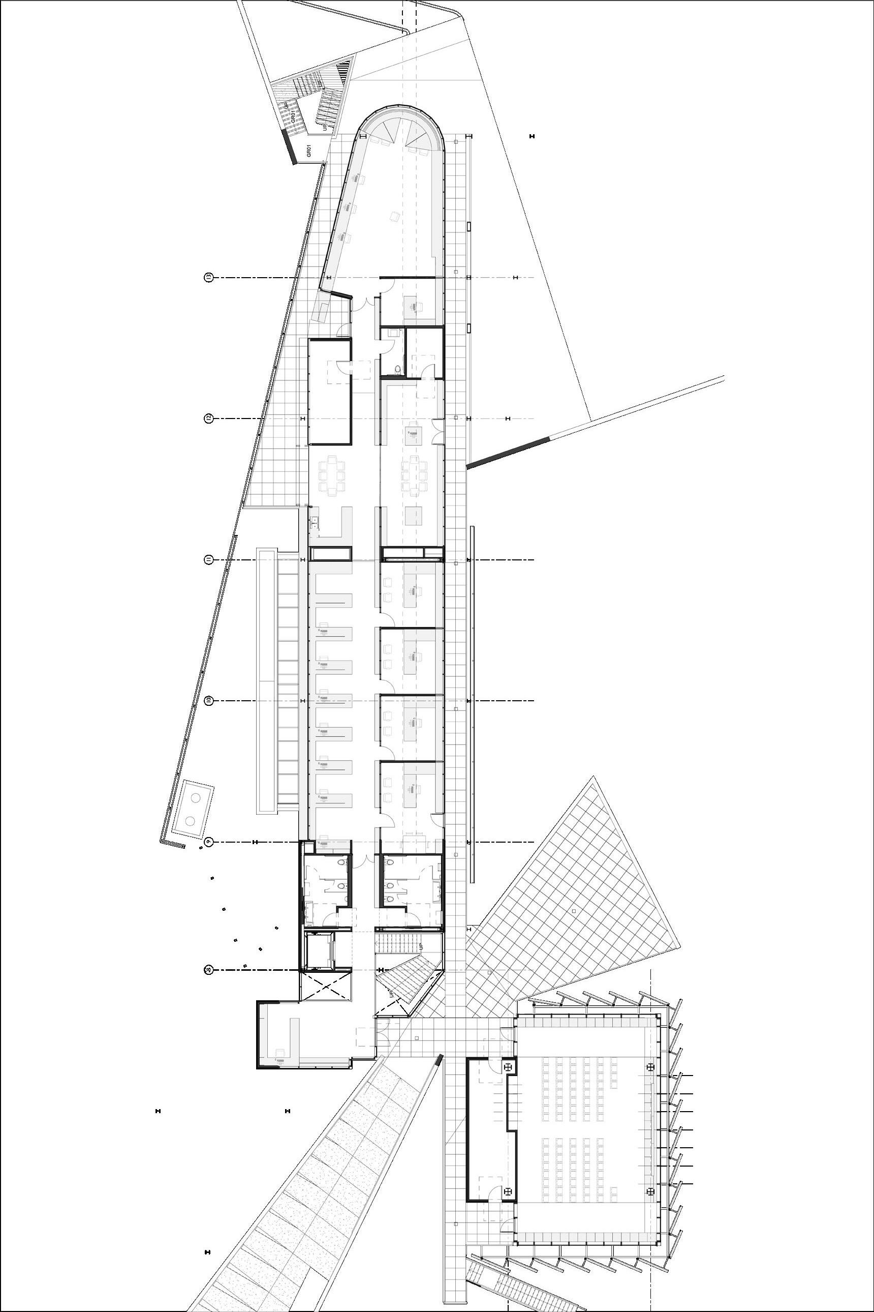
For METROPOLIS OF TOMORROW V2 OBM EXTENSION mega-city model is scaled down to form an office complex and New York skyline takes the form of the ceiling. The form of the base of OBM Headquarters is derived from the geometry of Hugh Ferris’s buildings and model kit produced earlier.
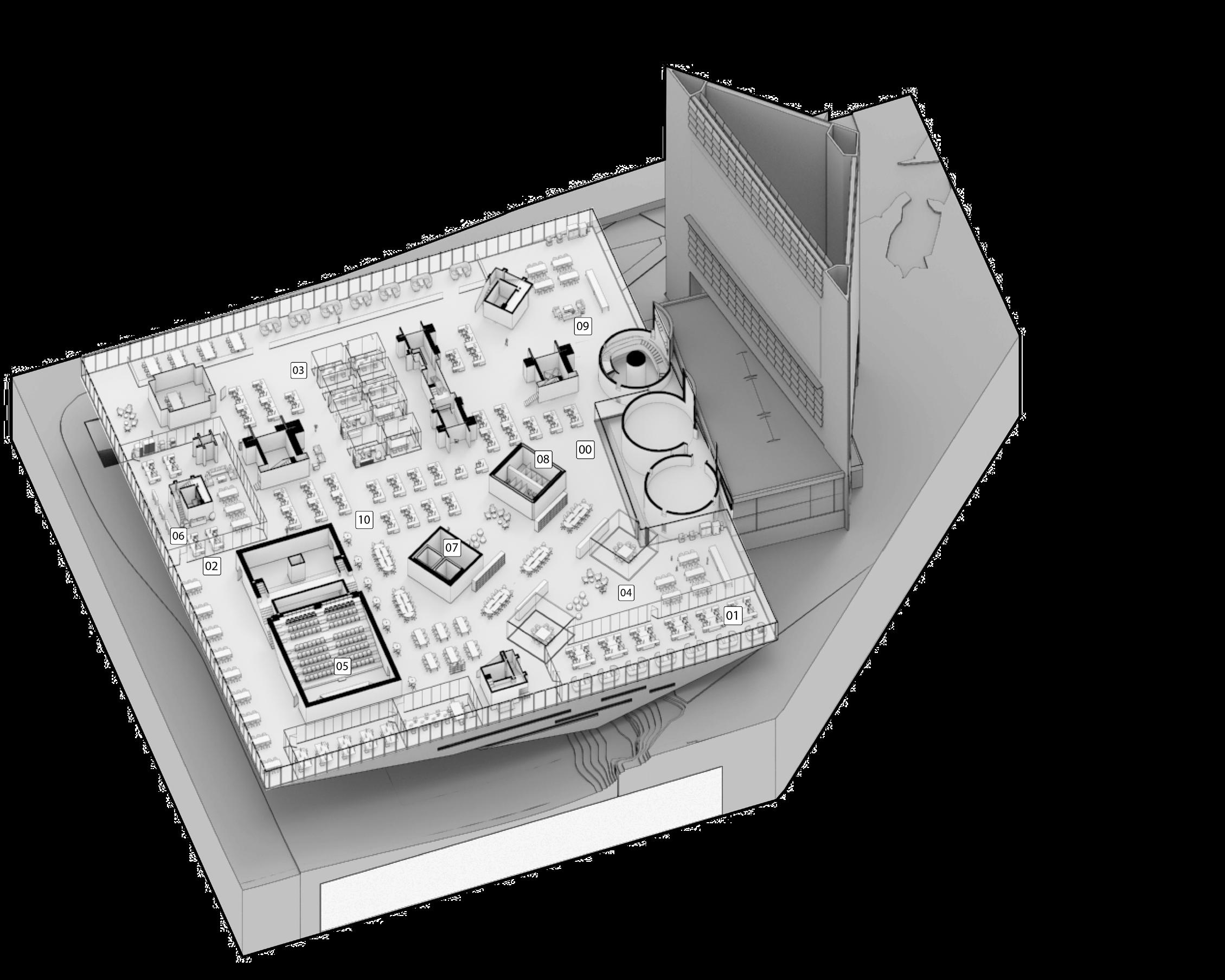
The project considers the kit models as mega-building which acts like a shell, and the interior is treated with inner liners to add a dual effect to the structure.
12 13
1. Entry
2. Open Office
3. Open Small Conference Area
4. Personal Office Space
5. Recreational Area
6. Auditorium
7. Enclosed Soundproof Zone
8. Elevator
9. Restroom
10. Coffee
11. Hot Desk
OBM headquarters showing the inner liners
Plan showing the office interiors
THE SECTION HOUSE
SCI-Arc | Fall 2018 Instructor - John Enright
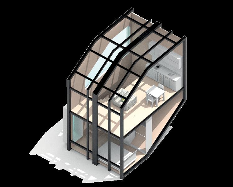
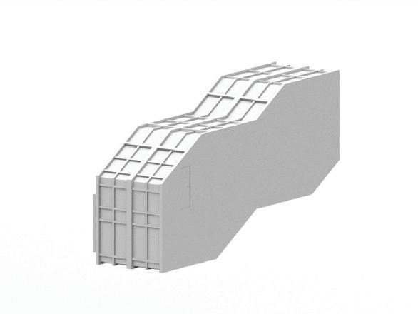
This project proposes utilizing unused land above sunken train tracks within the city of Paris to create affordable Pre-fabricated Housing that uses trains as primary delivery method of construction materials, reducing construction costs.
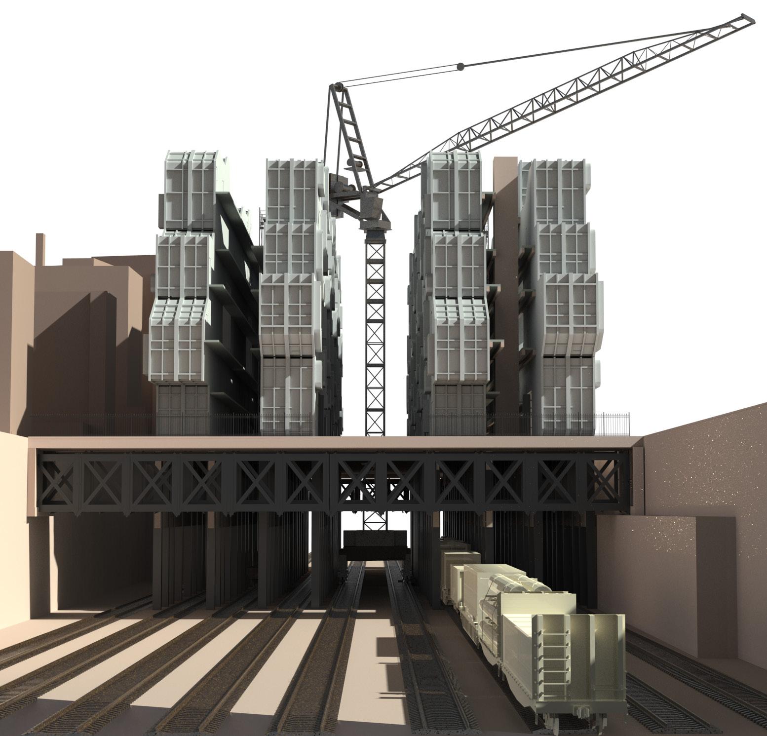
Logistics is a major concern for a city like Paris which is dense and does not have a spare space in any area, wealthy or otherwise.
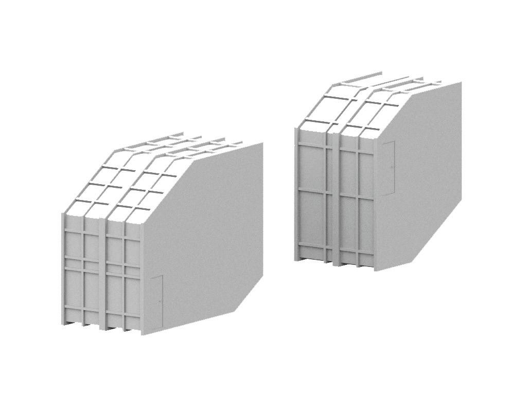
In this project, as the complete site is above railway tracks with prefabricated construction technology, all modules can be brought by trains to the location and lifted onto the site, which saves the city from being affected because of construction and keeping all the logistics away.
14
02
DESIGN PROCESS |
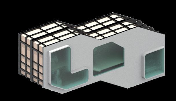
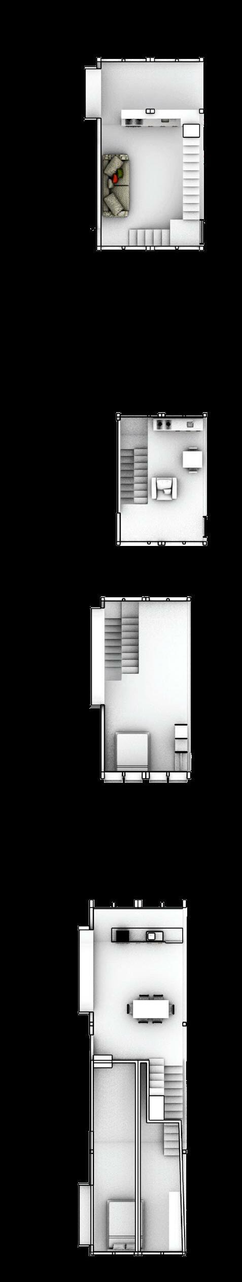
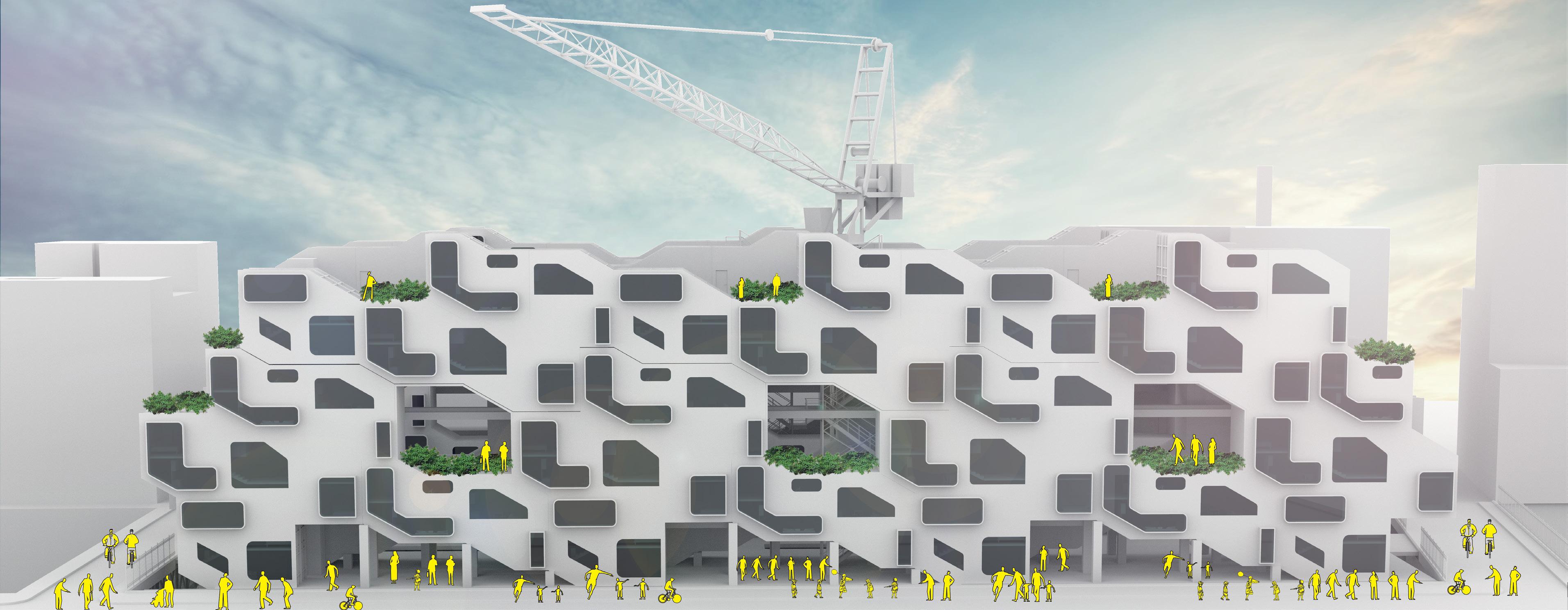
This design proposes a housing complex on land which is partially used in the city of Paris. Being above rail tracks allows for easy transportation of materials to assemble the structure. This design ideology can help in creating more A A combination of 1 – 2 Bedroom, 2 – 1 Bedroom and 1 – Studio apartment are designed as a tessellation which can be repeated linearly above the railway tracks. The voids on the ground floor are treated as commercial spaces and the voids on the upper floors are social spaces for residents.
16 17
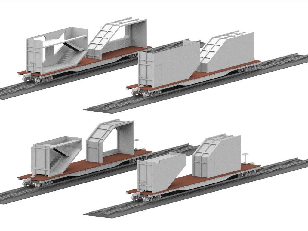
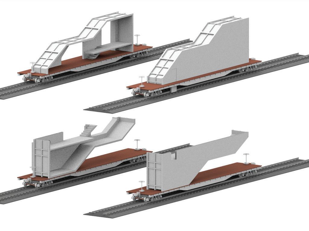
Pre-fabricated parts transported through railways and assembled on site
Studio Apartment Module
One Bed Apartment Module
One Bed Apartment Module
Two Bed Apartment Module
DESIGN |
If we see the map of Paris, it clearly contains 5 huge patches of land allocated for railways. All these train routes end right before entering the center of the city. This project controls the rising costs of housing in the sub-urban areas and allowing for affordable living.
The Section House is a prototype model placed along the “Rue de Rome” in the 17th arrondissement as an example of how the project might look in different parts of the city.
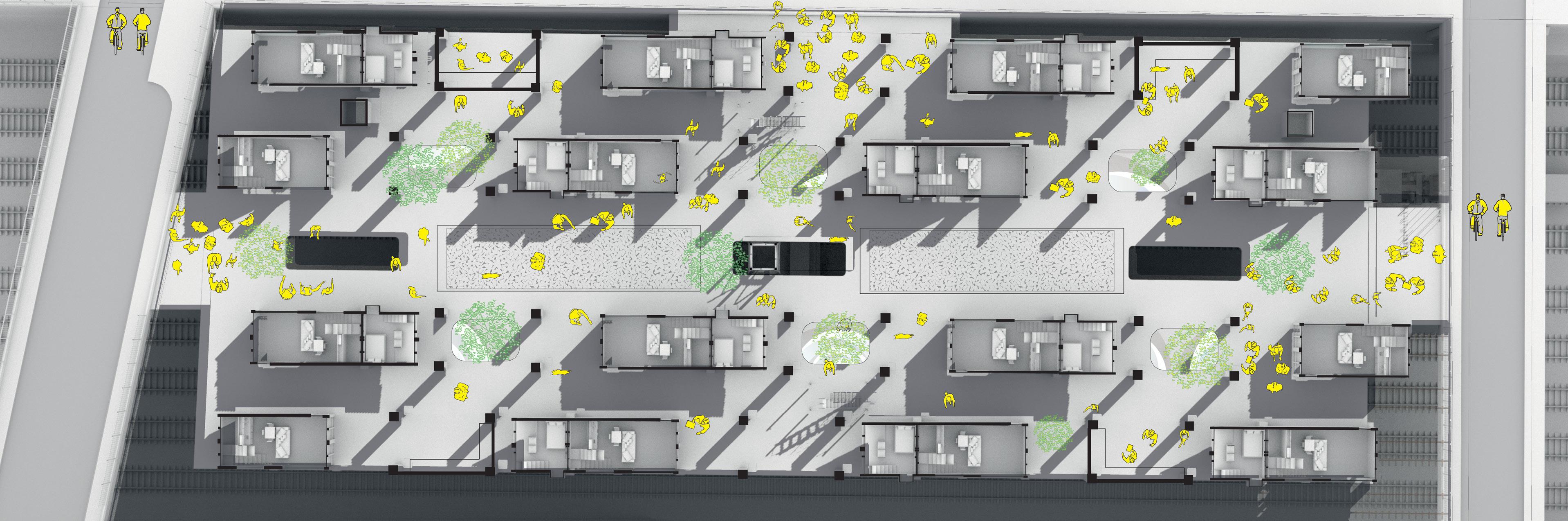
The design has 132 apartments comprising of both single and multi family dwelling units within a span of 100mtrs. With the same design process, the number of units can be extended to 12000 units with no land costs.
18 19
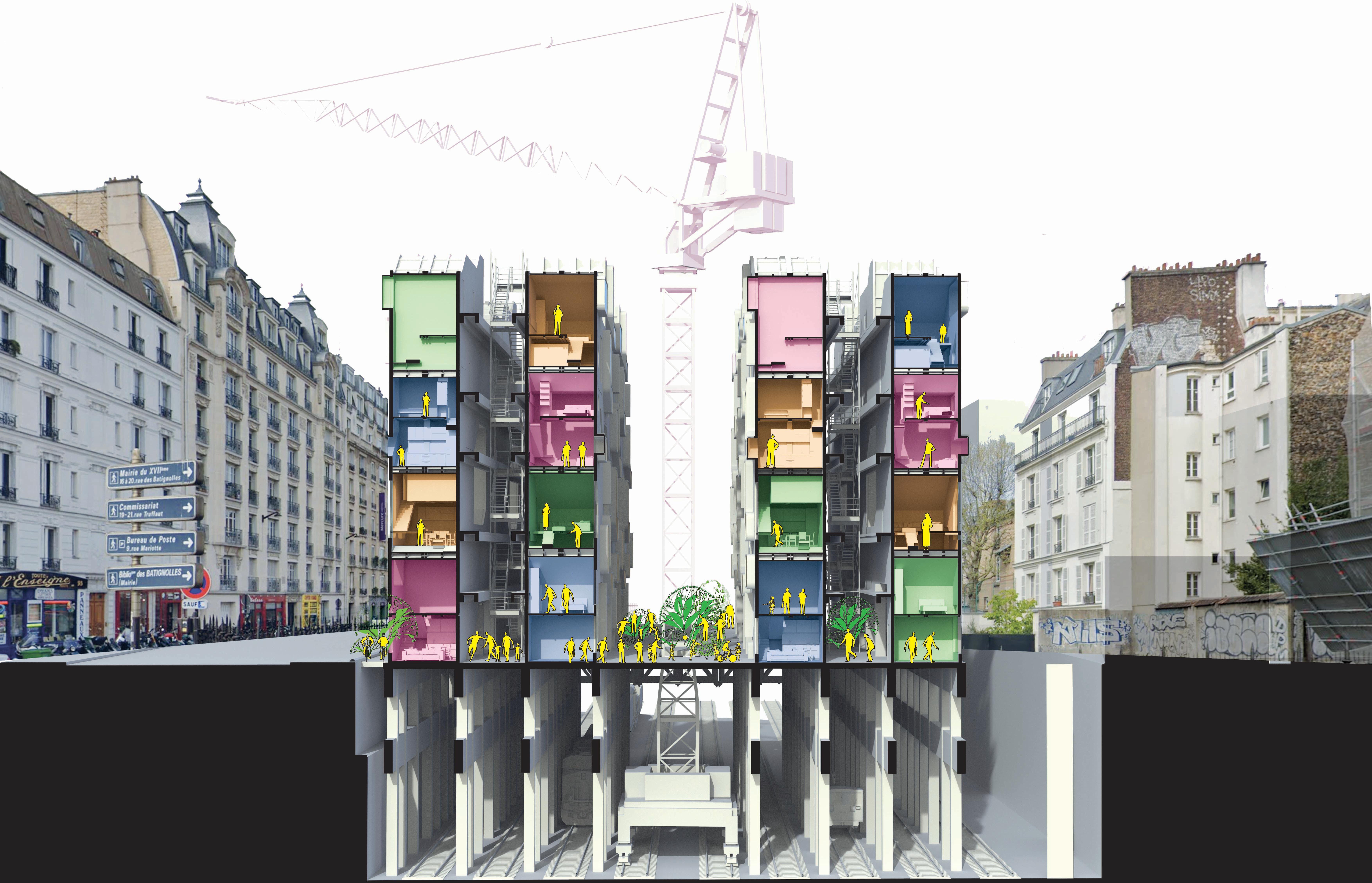
20 21 | THE SECTION
NEW ATLANTA CENTRAL LIBRARY
SCI-Arc | Spring 2019 Instructor - Jackilin Hah Bloom
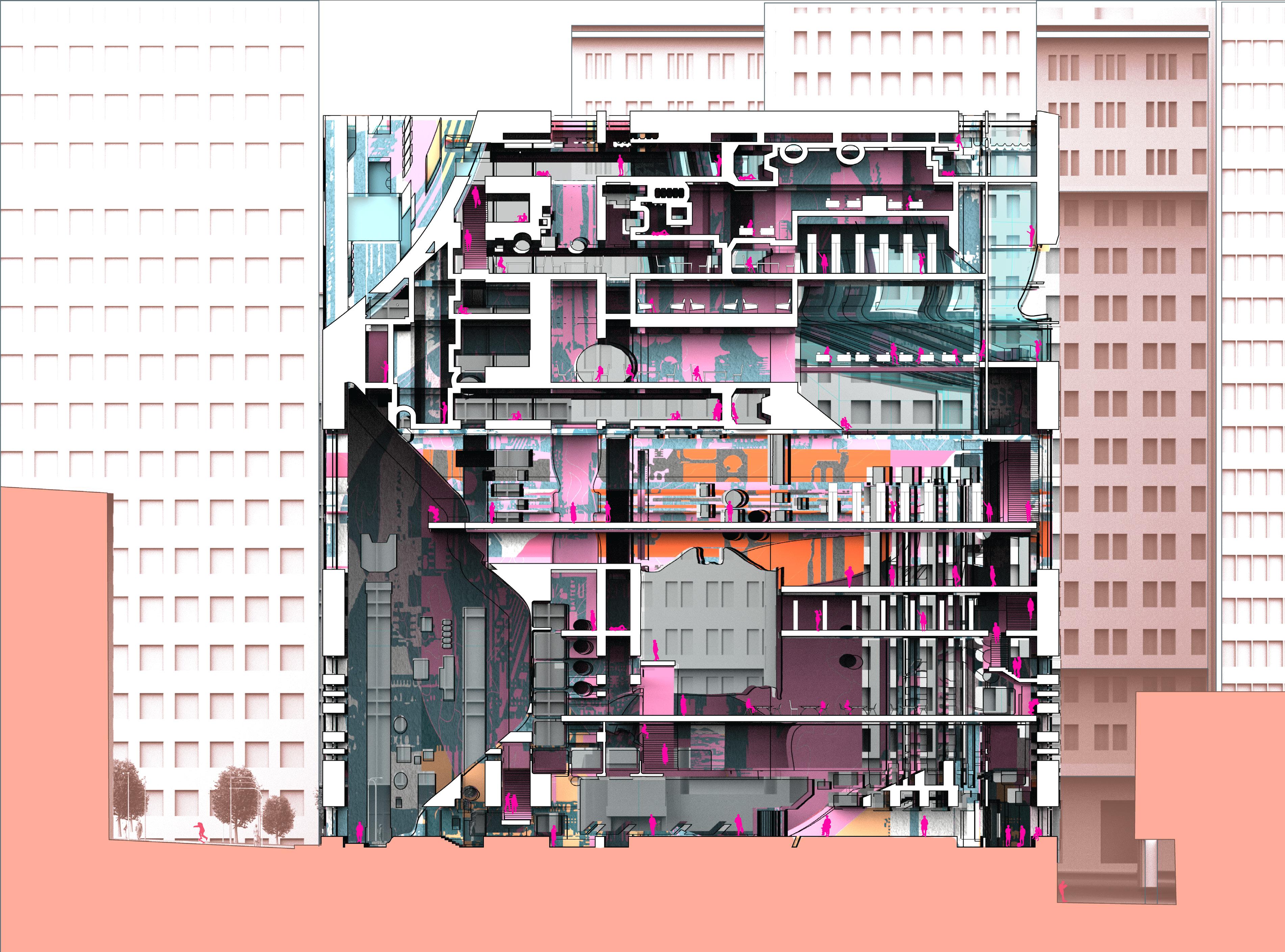
The library is a 40000 sqft structure that gives a civic presence on the street. The library features communal spaces for instruction, digital collaboration, technology support, and educational events and exhibits. For reading, flexibility is a core design principle.
Spaces are engineered for separate groups of users with different needs – each user wanting a customized reading experience for him. The library allows people to select the environment and tools that work best for them. It has large open stocks/ shelves for users who prefer to read a printed book and also a digital management and filing system for those who want to read an e-book.
22
03
24 25
| ELEVATION
DESIGN PROCESS |
ELEVATION
This library will be both; familiar and surprising, massive yet minimal. It will be a grand space with vast window looking into the landscape and the future. It will be a comfortable room with a view in which to learn and to grow, a place to answer a question, engage an idea, a place to riff on life as it is or daydream about life as it could be. The design and location of the library embraces the opportunity by creating an urban plaza and positions the vibrant, active library spaces to the community. The library will thus be a macro level project holding intellectually diverse people, knowledge and information; individual experiences in a cohesive environment.
26 27 |
PLANS |
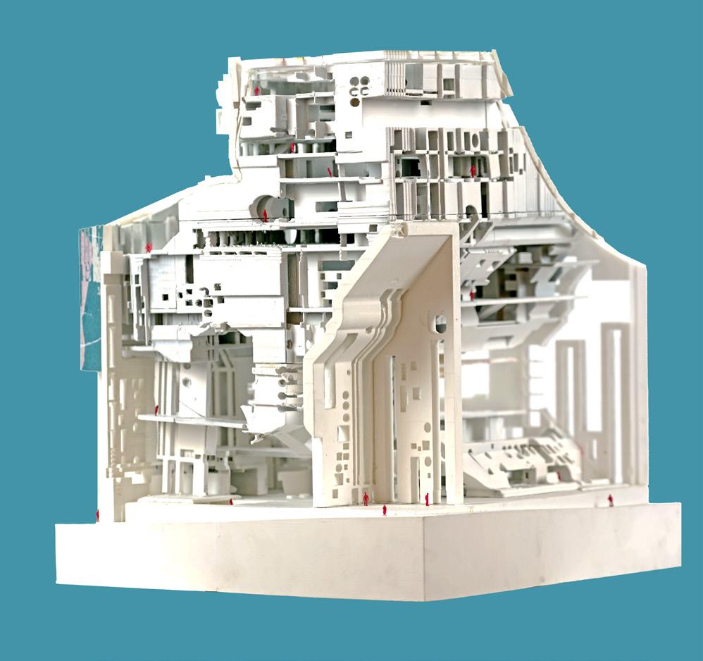
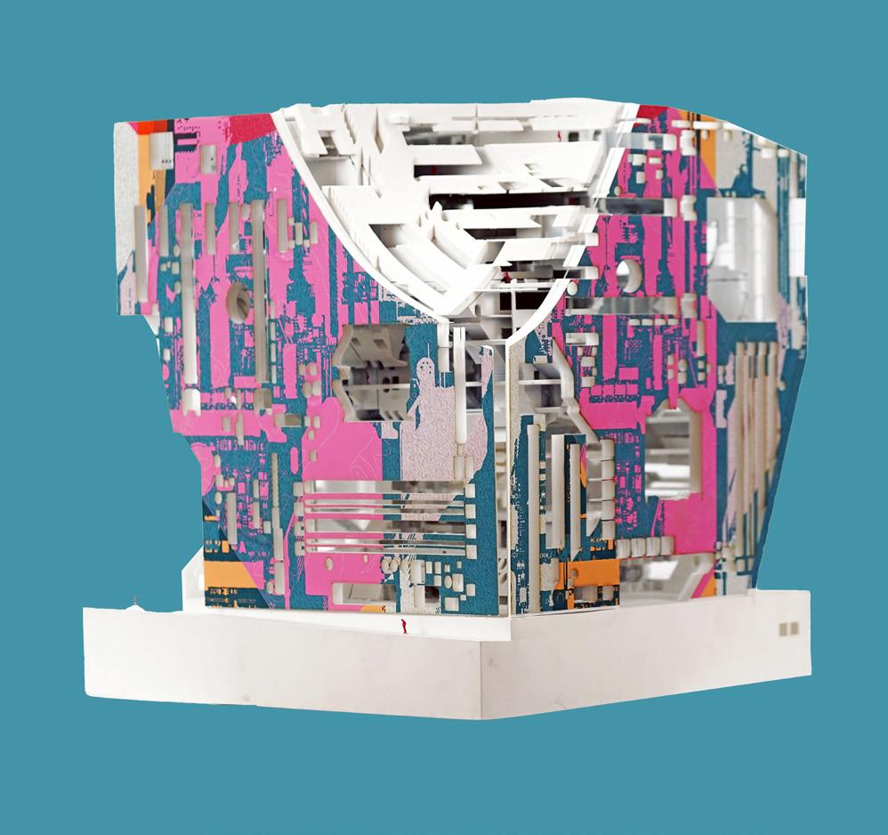
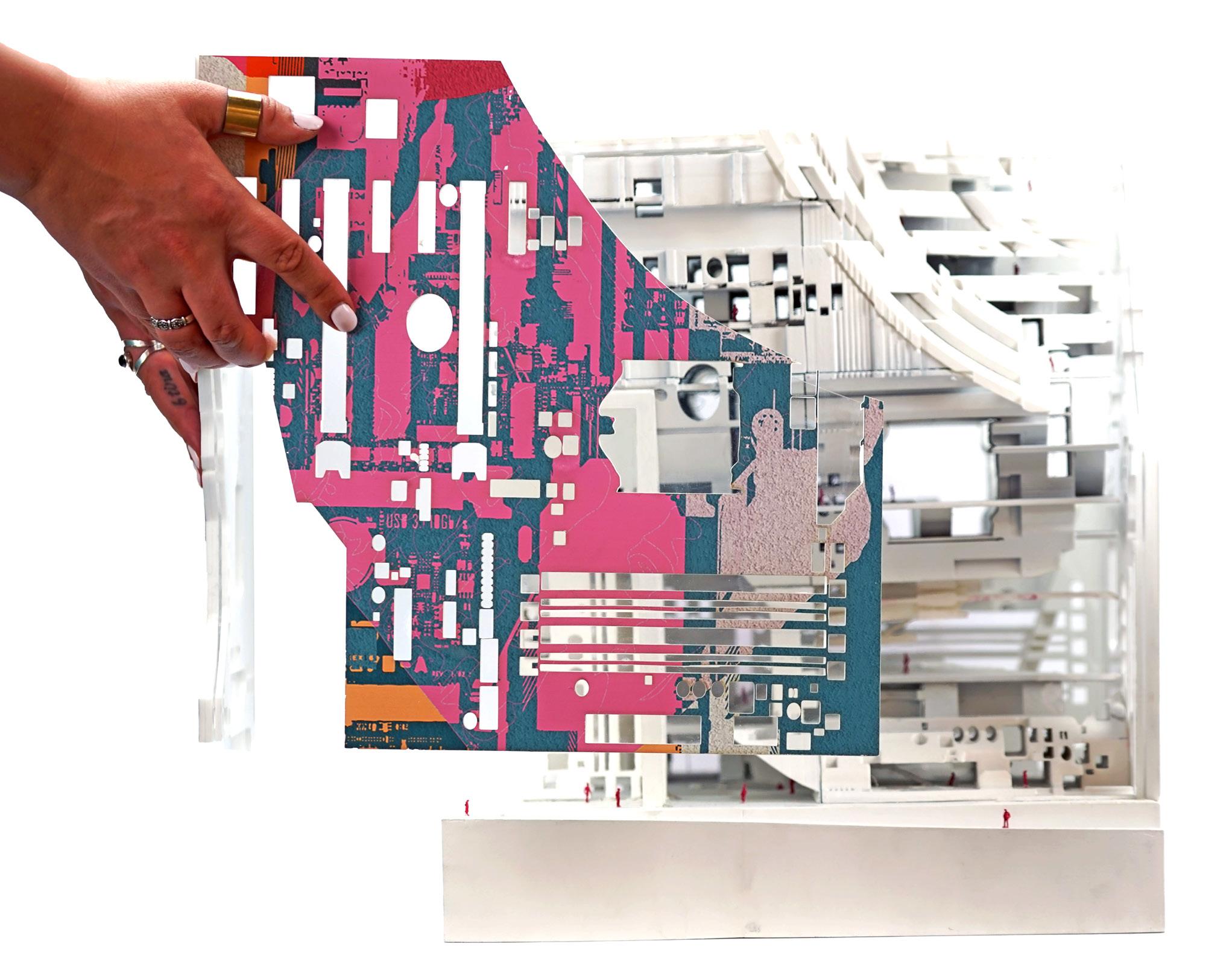
The massing of the library started by taking two different containers: a mother board being a carrier of information and a water floater being a tube of air. These two dissimilar objects were explored in unisonmotherboard replicating a digital analogous system creating interesting voids for light and scooping out major functional areas. The floater containers blend with these voids, enhancing fluidity in the structure and breaking the monotonous cubic-look of the structure.
28 29
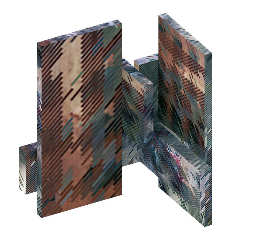
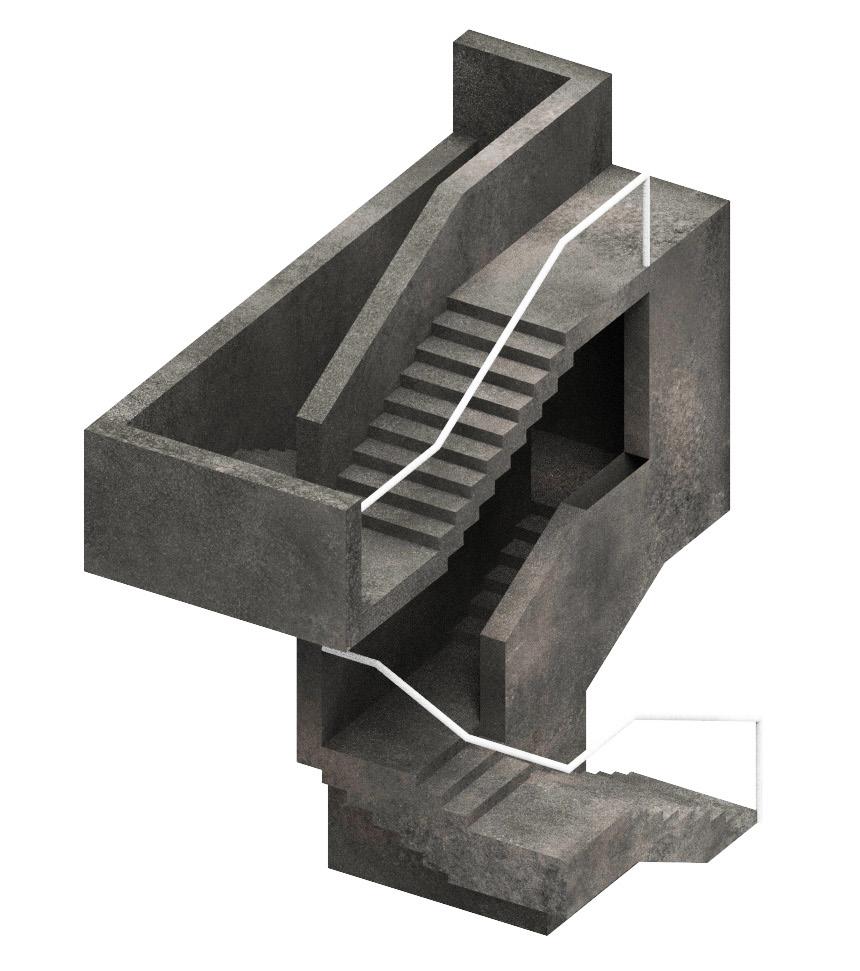
URBAN COMPLEXITIES
SCI-Arc | Fall 2018 Instructor - Casey Rehm
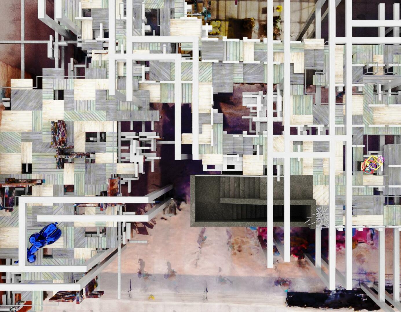
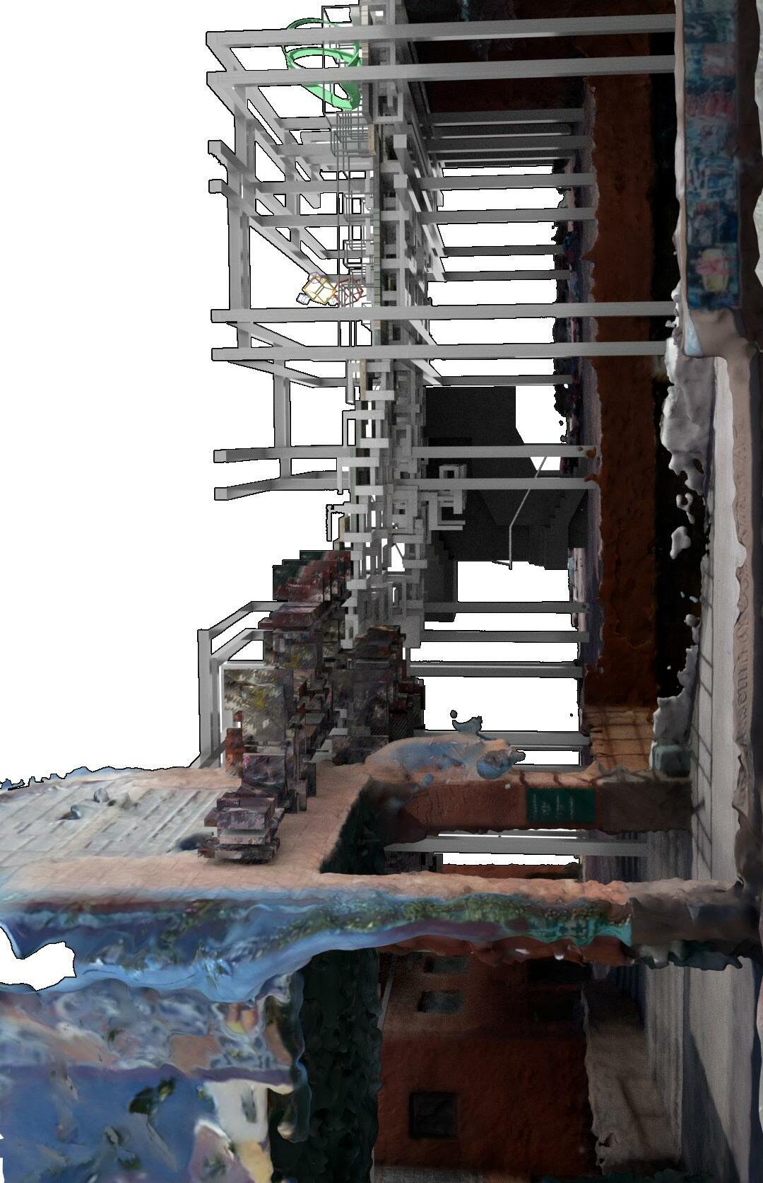
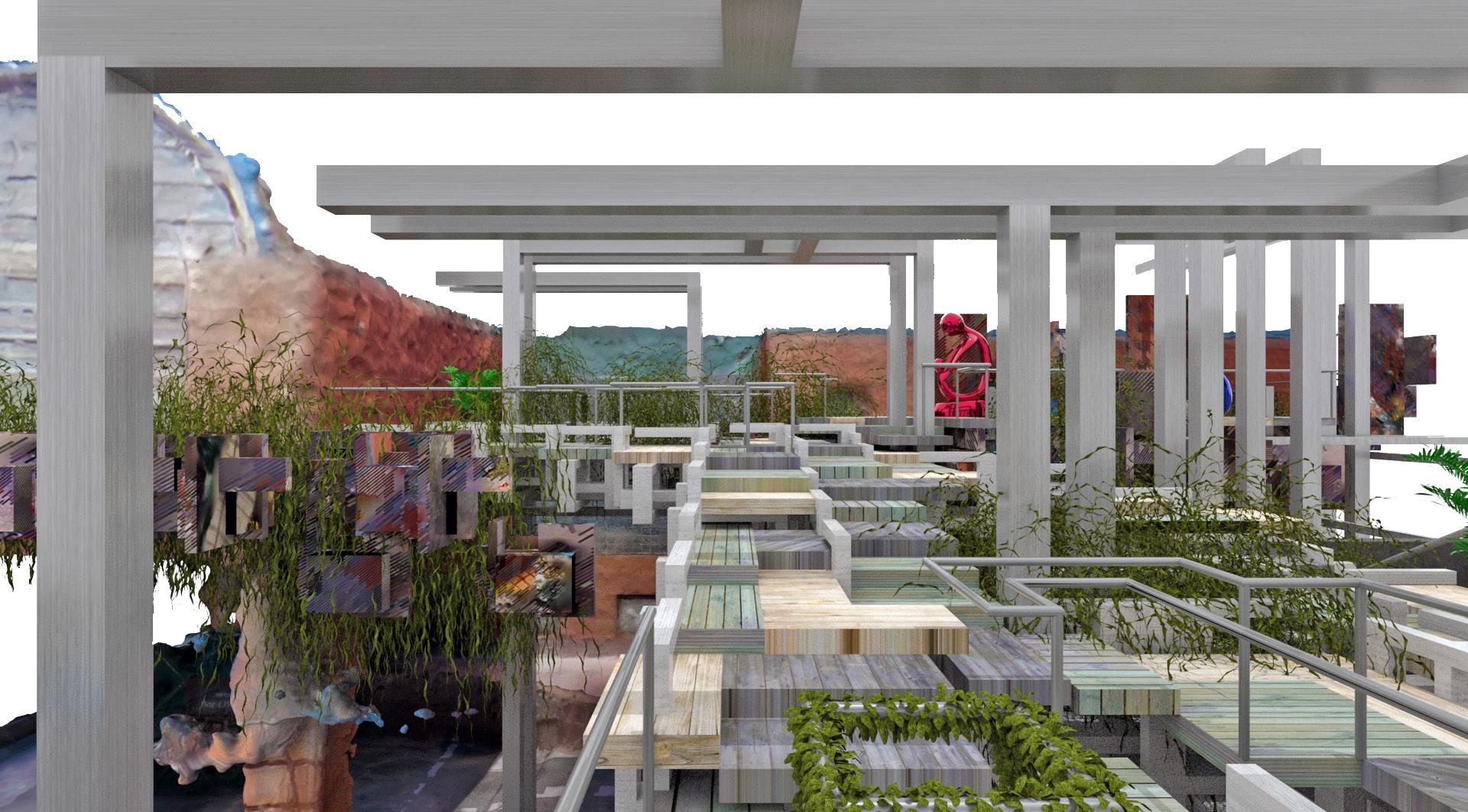
Urban Complexities, is an elevated sculptural garden as an extension to the plaza of MOCA in Downtown Los Angeles. The project aims to exemplify contemporary urban complexities through a hyperdense urbanism. The experience through this dense urban space, derives from the paradigm of traditional English sculptural gardens. The project rethinks how art is displayed in the contemporary age of social media, where the experience is just as important as the art. This gives an experience of informal engagement, allowing the viewer to see art with a complexity of backgrounds. Planes are used to isolate pieces of art, developing more engaging user paths within the urban garden.
30
04
DESIGN PROCESS |
The site is infilled with components allowing the design to have complexity within itself. The design comprises of 3 modular components which formulate an elevated platform. The components are - egress tower, structural decking, and an isolation wall. The tower acts as a conjoining element in the design where it showcases as an entry to the exhibition space. As we see the design, the components are growing towards the tower. This is achieved by developing an agent network with the tower being the attraction point, for the agents, furthermore manifesting the urban sculpture garden. This defines design as an addition to MOCA. As a transition into the next era of architecture, the design blends with the present structural ideology evolving into a network of modular components.
32
GARDEN VIEW |
DETAILED DOCUMENT
SCI-Arc | Fall 2019 Instructor - Herwig
This project investigates issues related to the implementation of design: technology, the use of materials, systems integration, and the archetypal analytical strategies of force, order and character. It reviews basic and advanced construction methods, analysis of building codes, the design of Structural and Mechanical systems, Environmental systems, Buildings service systems, the development of building materials and the integration of building components and systems. The intent of this project is to communicate complex building systems for the built environment and to demonstrate the ability to document a comprehensive architectural project.
36
05
Baumgartner
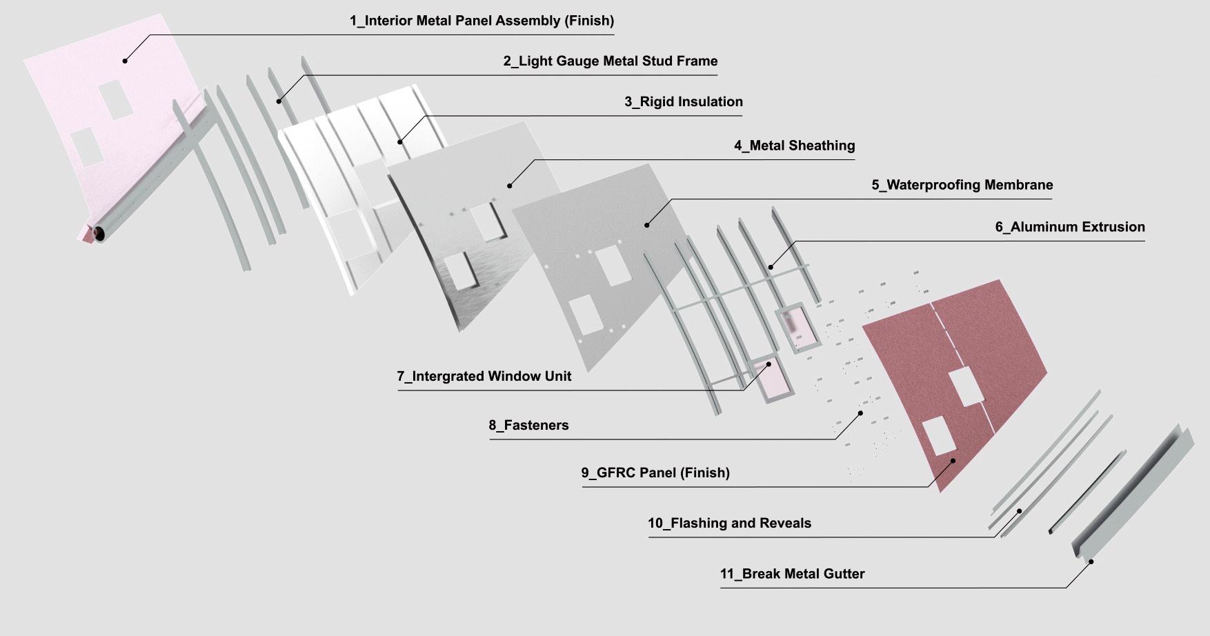
MATERIAL ANALYSIS |
GFRC Panels (Red)
AUDITORIUM CHUNK
GFRC Cladding
Low E-coated glass curtain wall
Seating Assembly (as per specs)
Low E-coated glass curtain wall
GFRC Panel (Light Grey)
Champagne Anodized Aluminum reveal
READING HALL CHUNK
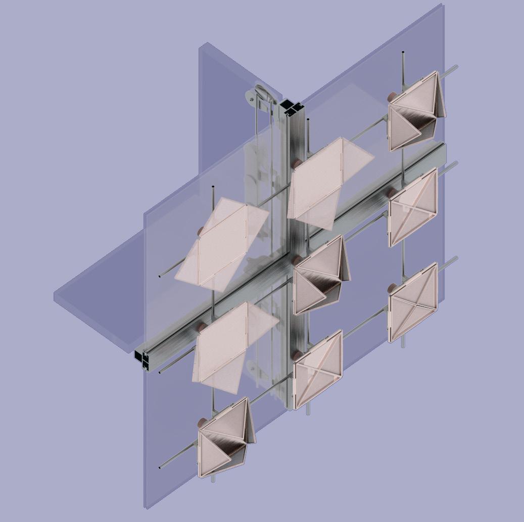
Kinetic square shading device
Colored concrete in-situ staircase
Colored concrete in-situ landscape
Aluminum framework for glass
Concrete topping slab
Converging system or Escalator
Framed guardrail with aluminum finish
38
39
PANEL ASSEMBLY |
MECHANICAL ASSEMBLY
• Horizontal glass spandrel
• Wire cable support
• Cable attachment
• Vertical structural glass spandrel
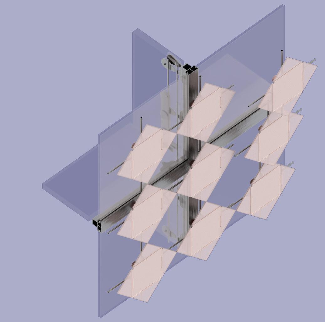
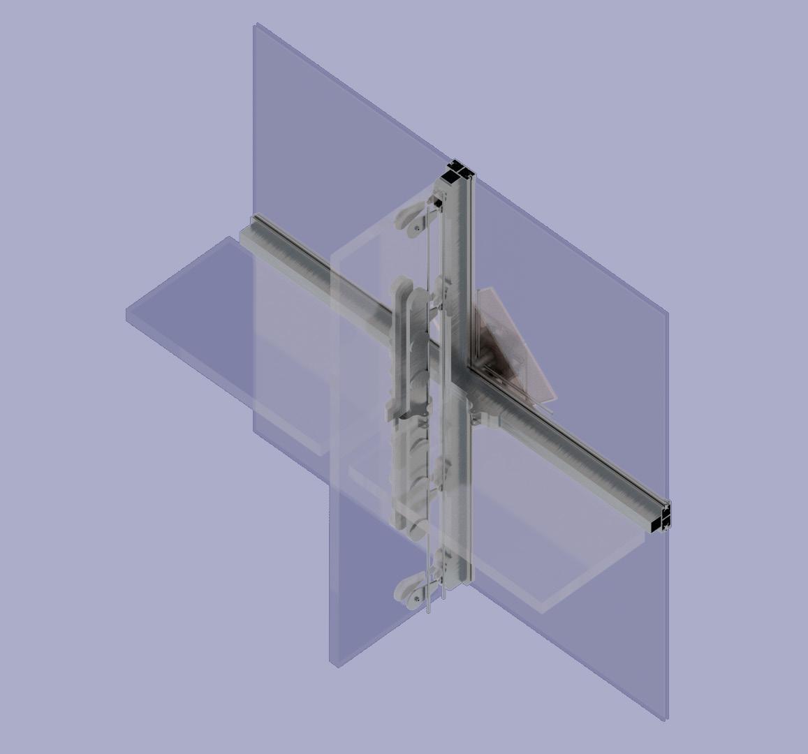
• Clevis attachment for glass spandrel
• Low E-coated glass
• Titanium extrusion
• Translucent Fabric
• Spiral Joint system
• Frame extrusion
• Stiffening rods
• Clevis attachment
• Rubber gasket
• Gear Bearing
• Metal couplings
• Pivot Barings
• Mechanical Rotar
Electronically powered Kinetic shading device attached to wire cable
• Coated aluminum sheet
• Translucent Fabric
• Spiral joint system
• Frame extrusion
• Stiffening rods
• Clevis attachment
• Rubber gasket
• Gear bearing
• Metal couplings
• Pivot barings
• Mechanic rotar
• Coated aluminum sheet
40
41
FONDATION LOUIS VUITTON
SCI-Arc | Fall 2018 Instructor - Maxi Spina and Randy Jefferson
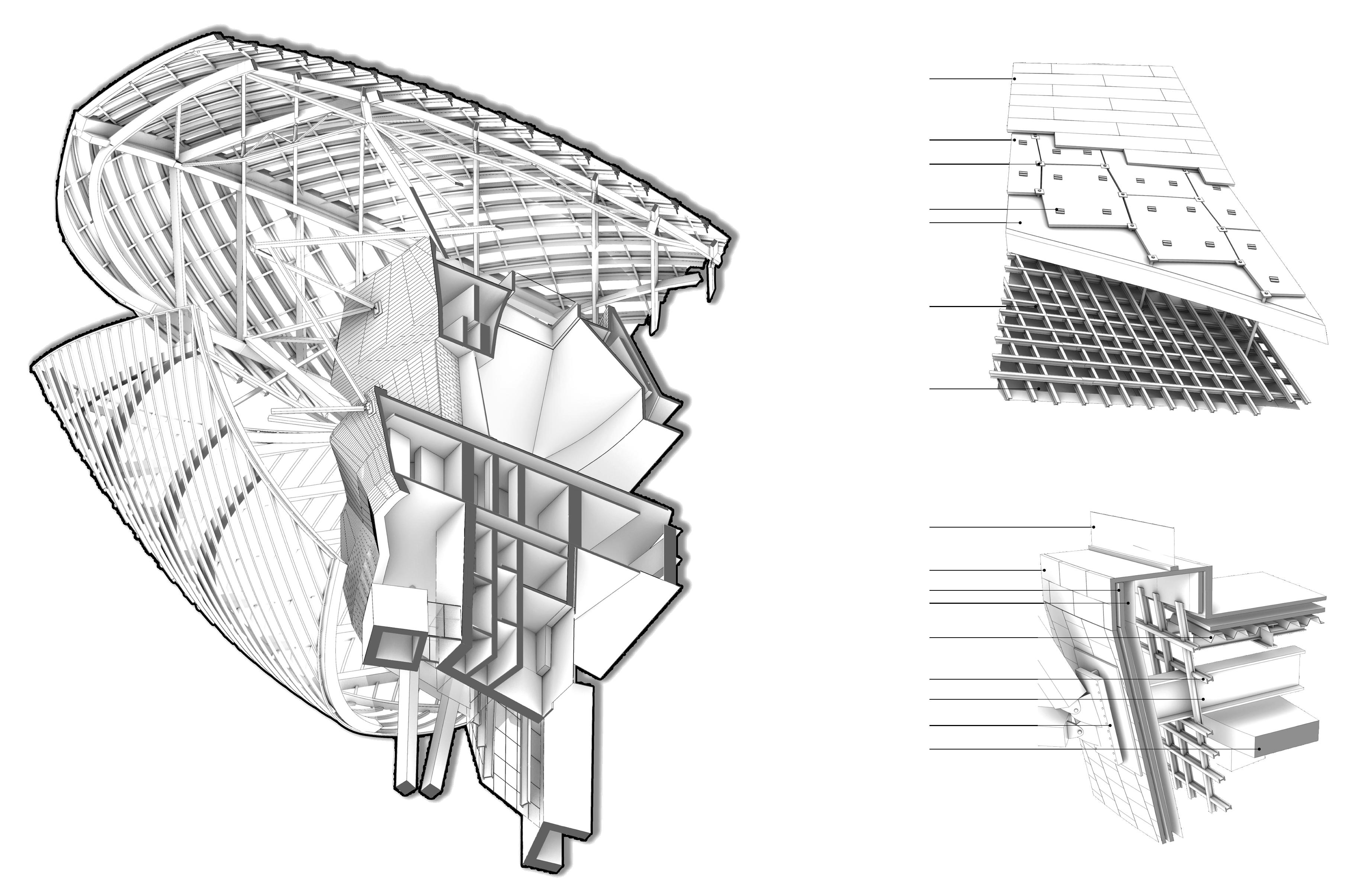
The project is a transformation of a chunk transformation of Fondation Louis Vuitton by Frank O’ Gehry.
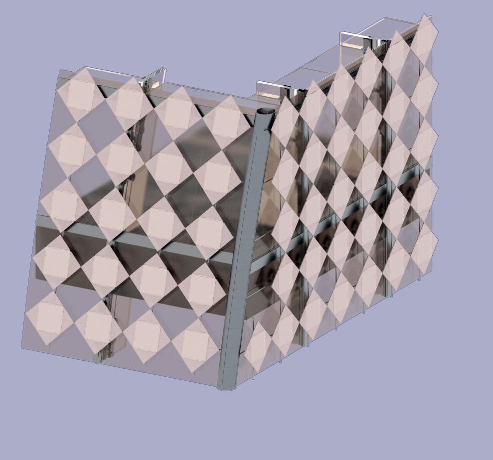
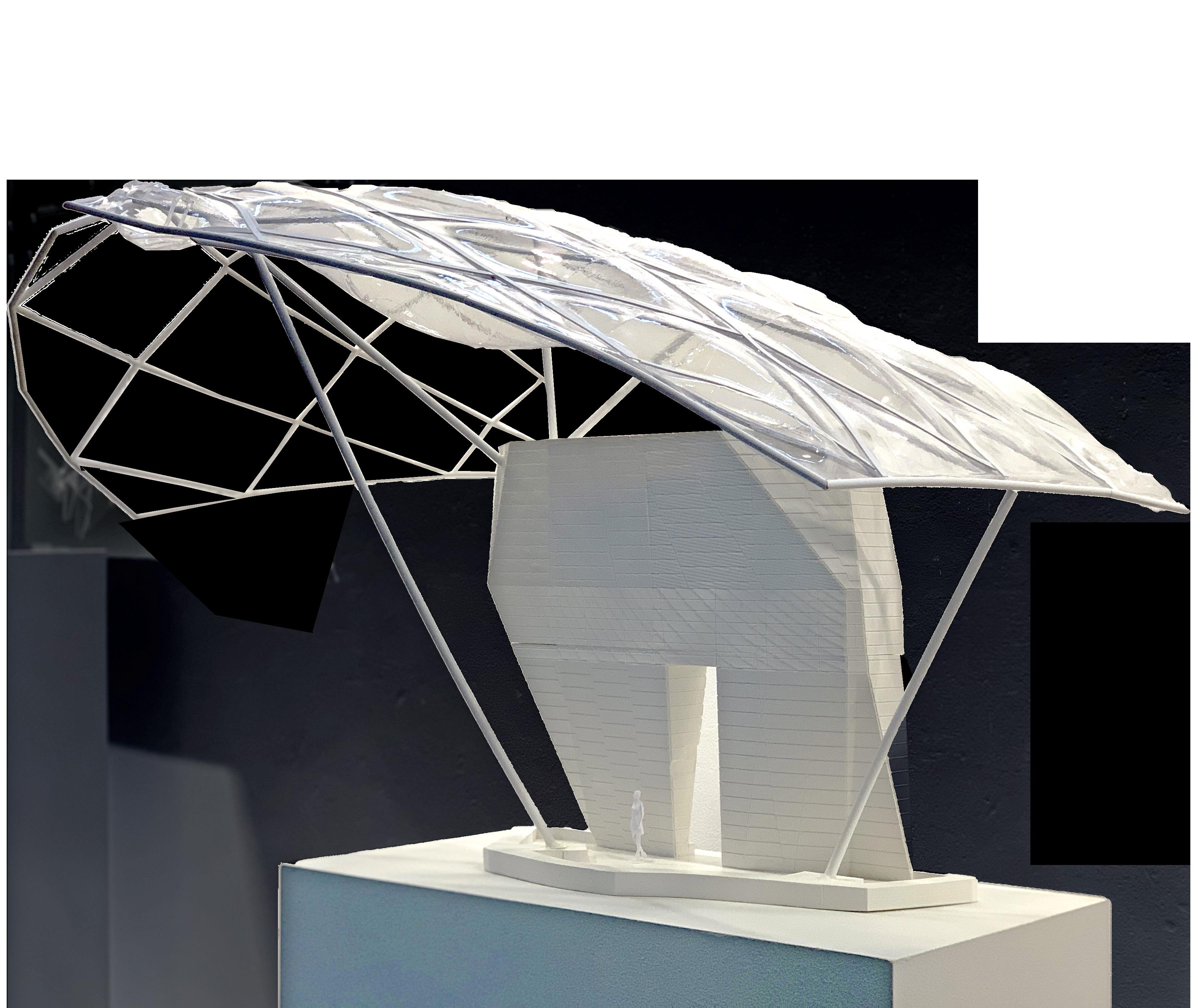
The transformation proposes replacement of existing glass sails with ETFE panels. Ethylene tetrafluoroethylene(ETFE) is a high strength plastic polymer which is design to have a strong corrosion and heat resistance. When used in pneumatic panels, ETFE becomes a great roof material. The plastic is self cleaning and recyclable, decreasing the amount of maintenance needed. The material is lightweight and can span longer distances than glass, decreasing the amount of structure needed to support the panels.
42
06
ENVELOPE ASSEMBLY
Envelope system
Aluminum mullions connect timber frame to aluminum glass mullions
Secondary system
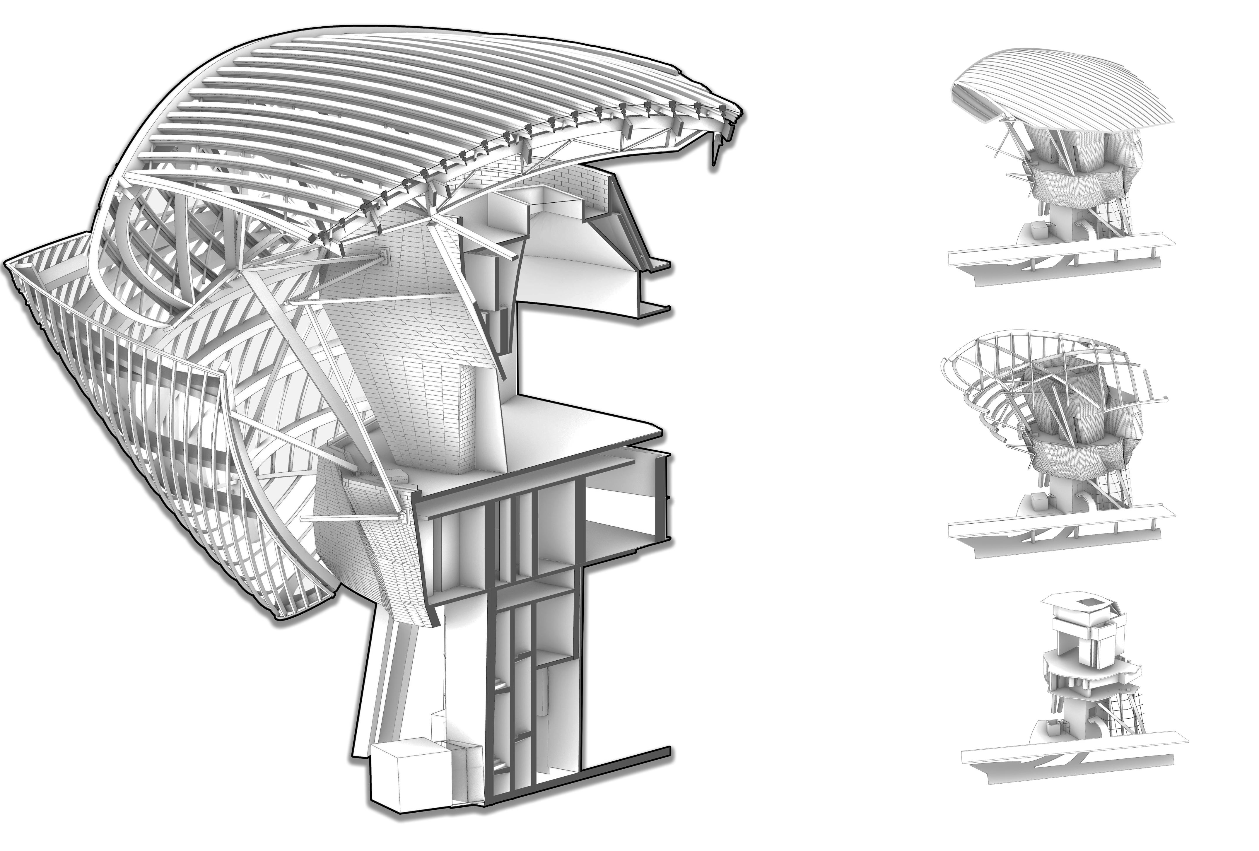
Steel beams connect from interior concrete slabs to additional steel support and timber frame
Primary system
Concrete and columns connect to underground foundation
44
45
|
Top Aluminum Mullion
Tempered Glass Glazing
Bottom Aluminum
Timber Beam Frame
Trusses
Glass - sail pull-away
Top Aluminum Mullion
6mm Tempered Glass
Sealant
1.52mm layer with 50% opacity reflective white frit
Aluminum Mullion
Timber Beam Frame Steel Joint
Steel beam
Glass - sail cross section
Design Development
Terrace
Retention Basin
47
| ENVELOPE
ARTICULATION


48
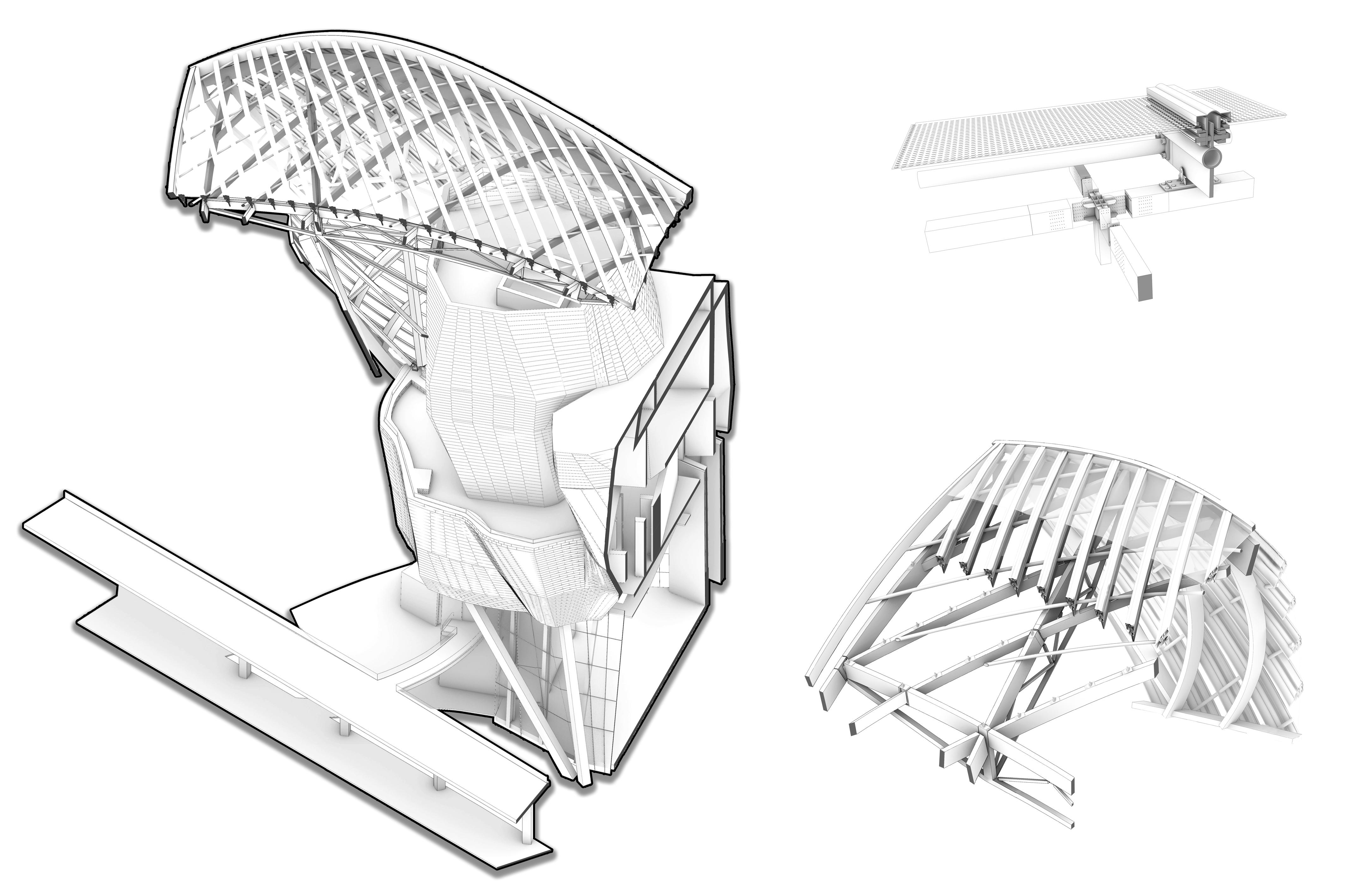
Iceberg pull-away
49 | ENVELOPE ARTICULATION
Iceberg cut-away
Slip cable
ETFE panel
Steel chair
Steel chair
Air intake value
Inflation Supply duct
Diagrid Aluminum pipe
Slip cable
Concrete foundation walls
ETFE panel
Steel chair
Aluminum mullion
ETFE aluminum mullions
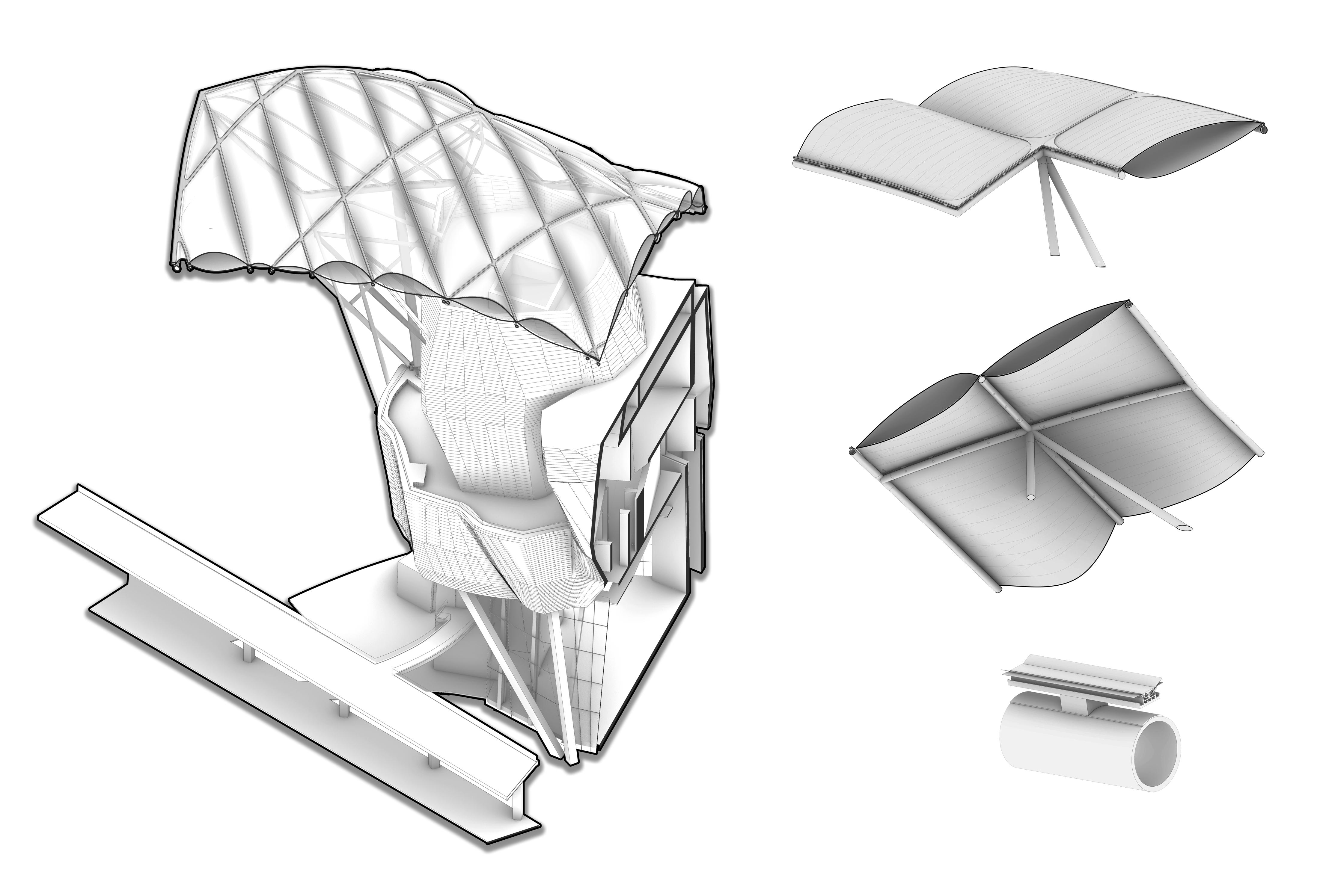
With ETFE we can decrease the thickness of the sails structure, giving Fondation Louis Vuitton a more lightweight aesthetic. The reduction in Structure allows for visitors to have a clear view Paris and the surrounding Park. The use of fabric ETFE panels relates to the Fondation Louis Vuitton and the company’s program.
50
ETFE Panels
51
Design Development
Terrace
| TRANSFORMATION
Retention Basin
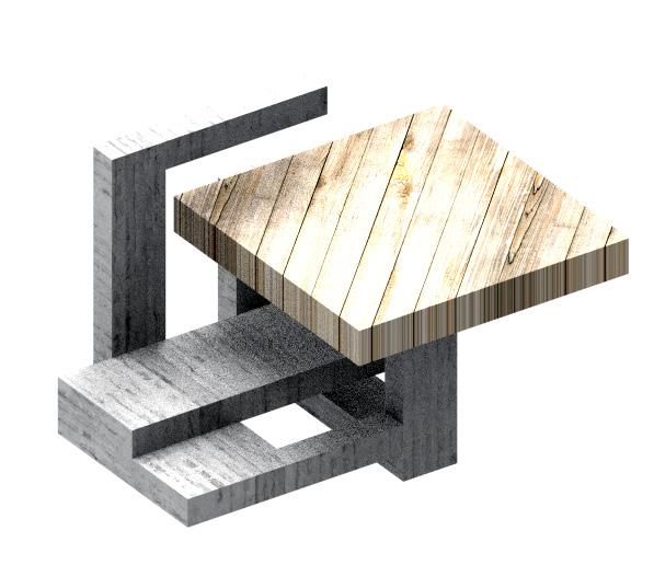
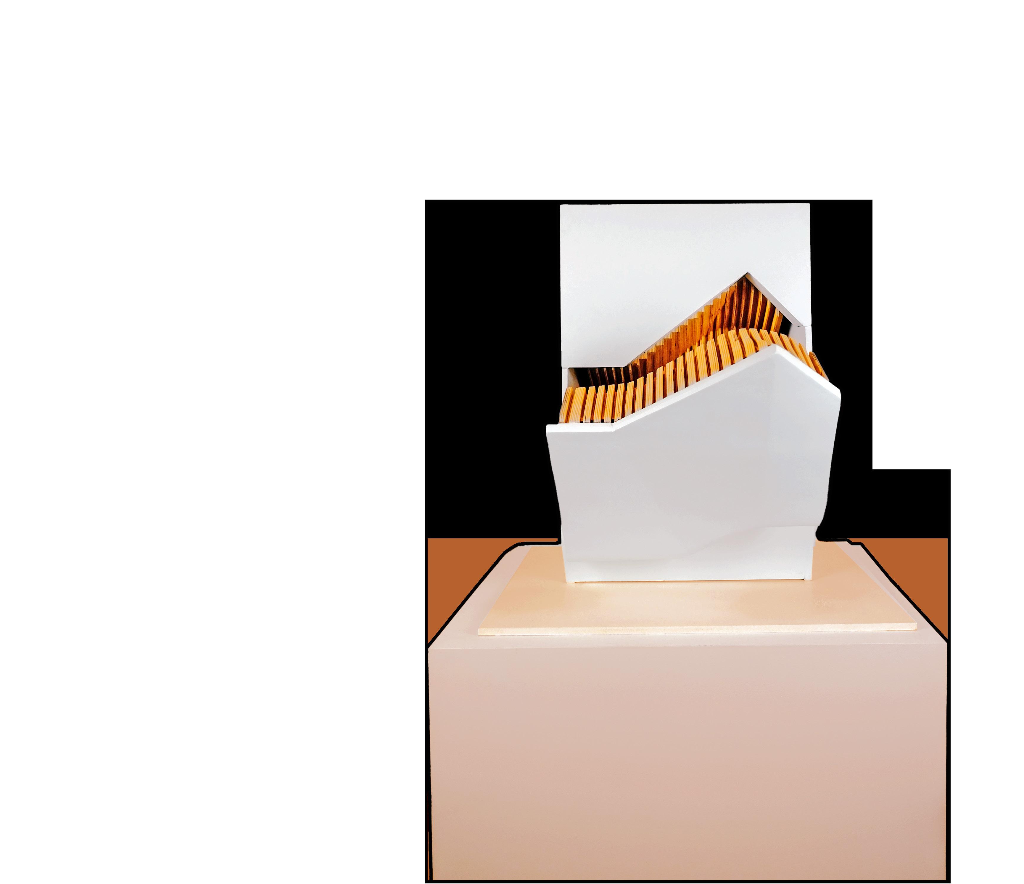
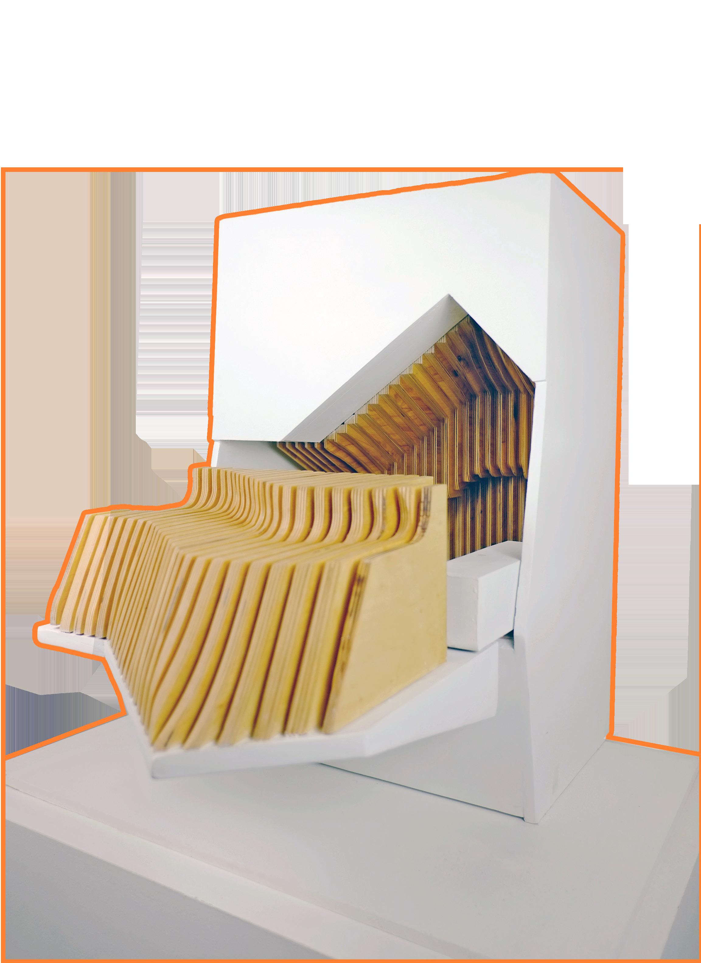
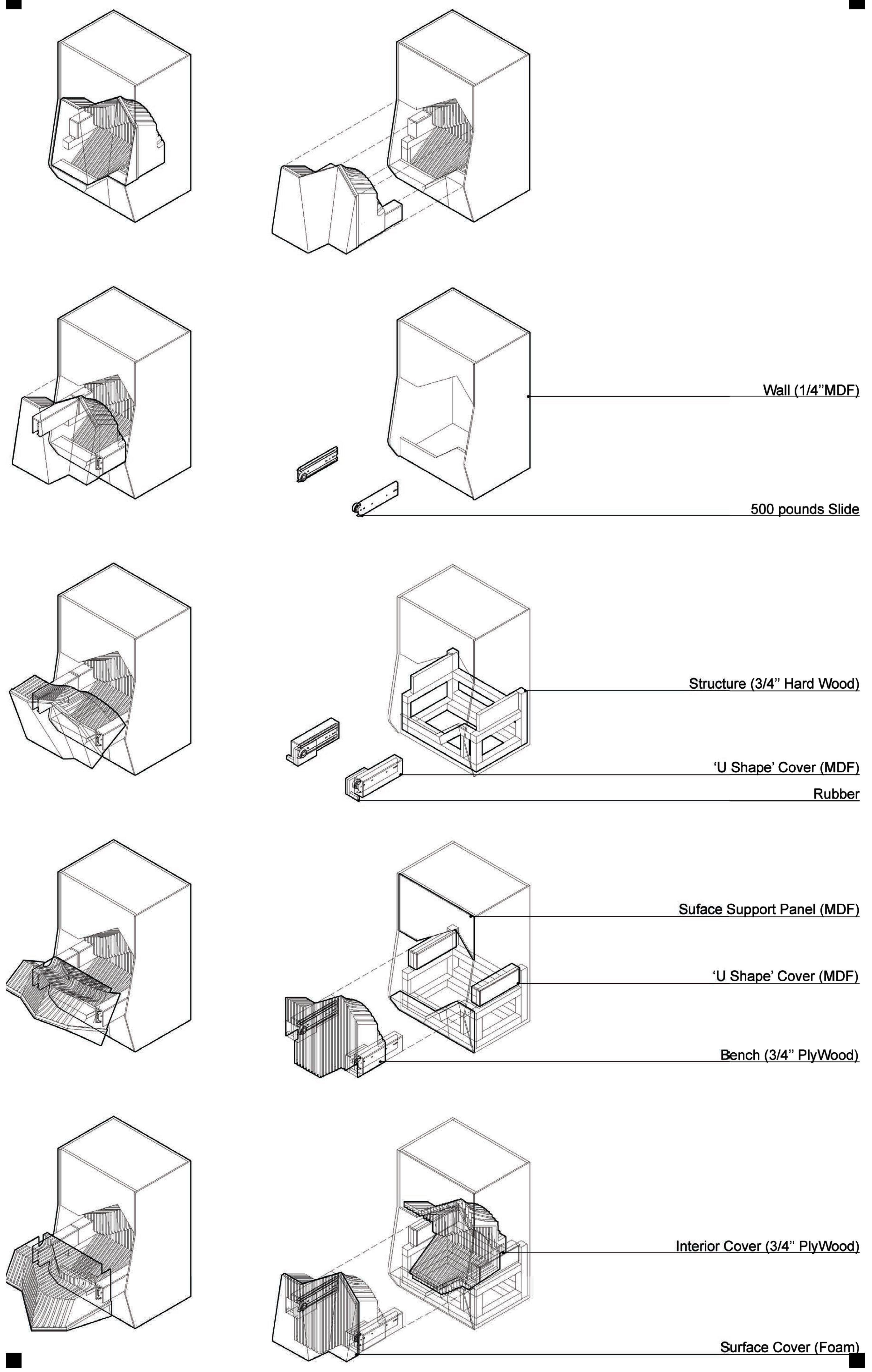
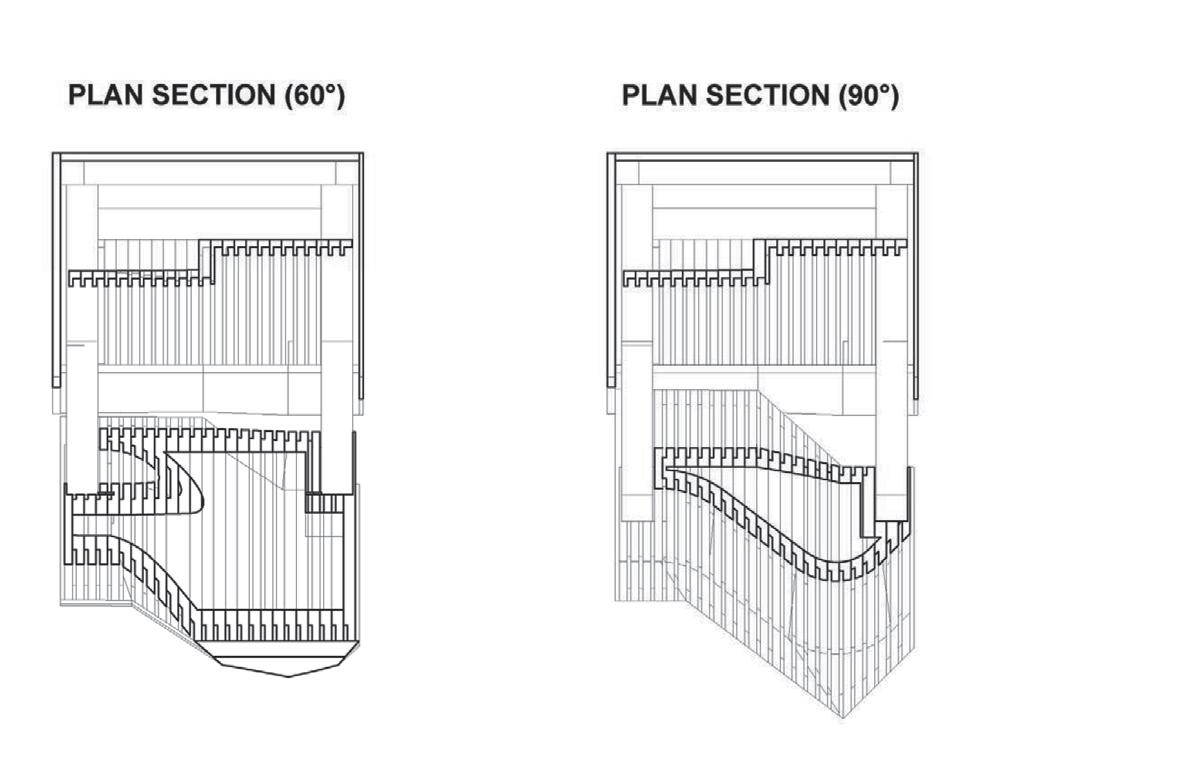
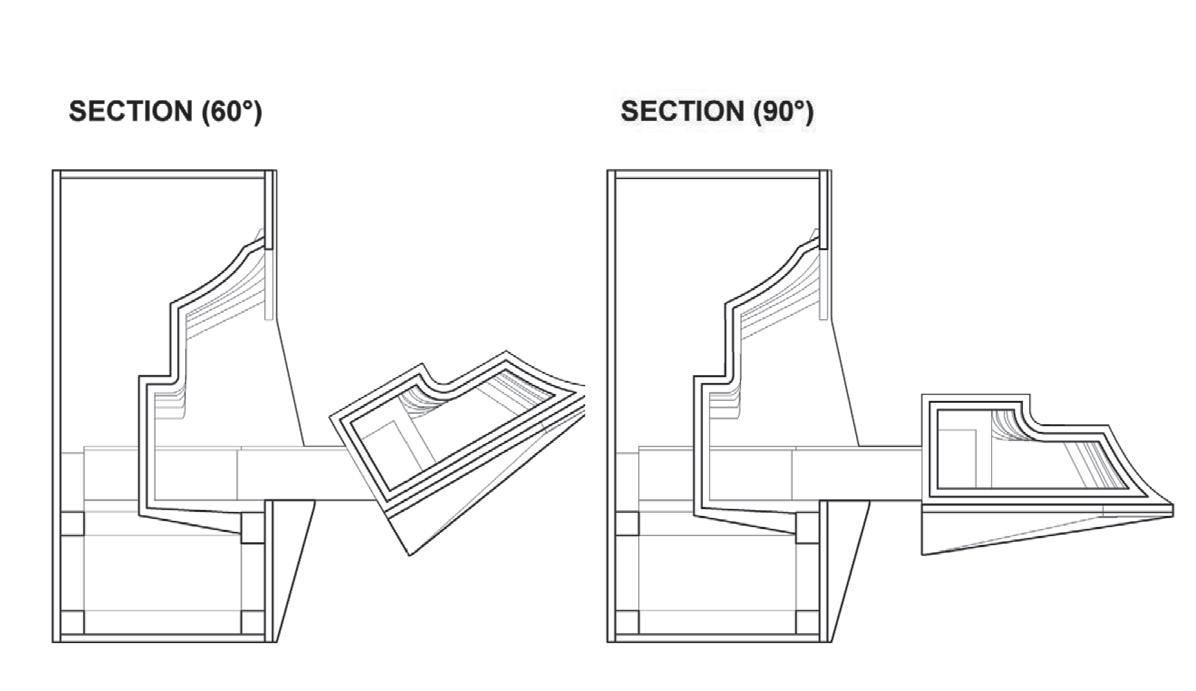
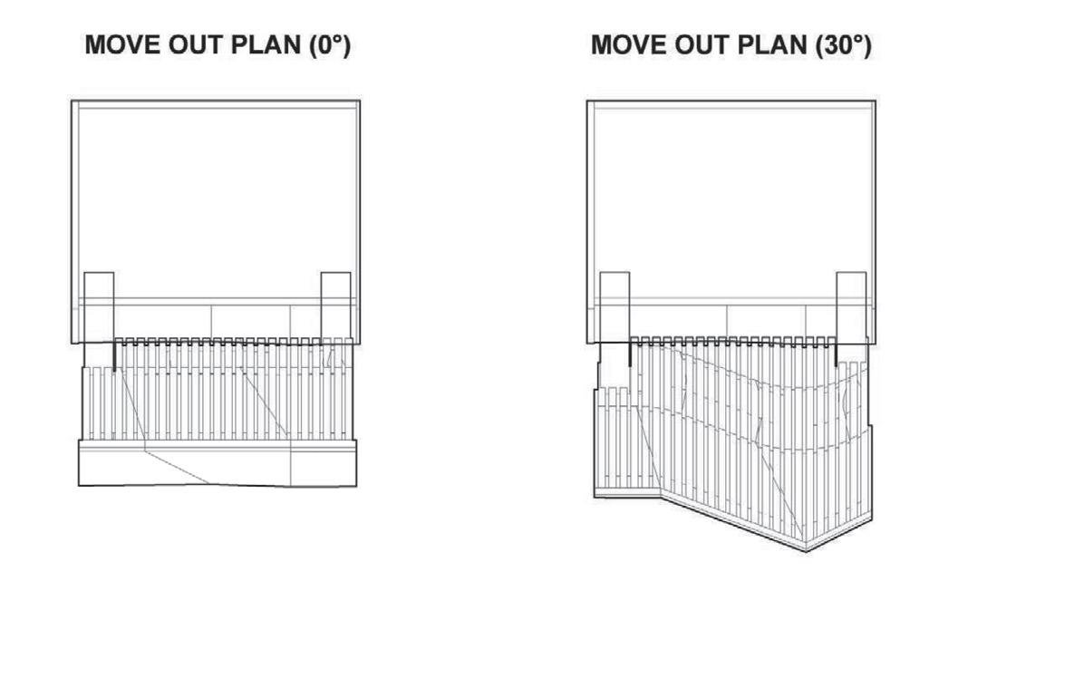
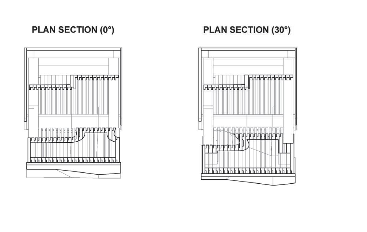
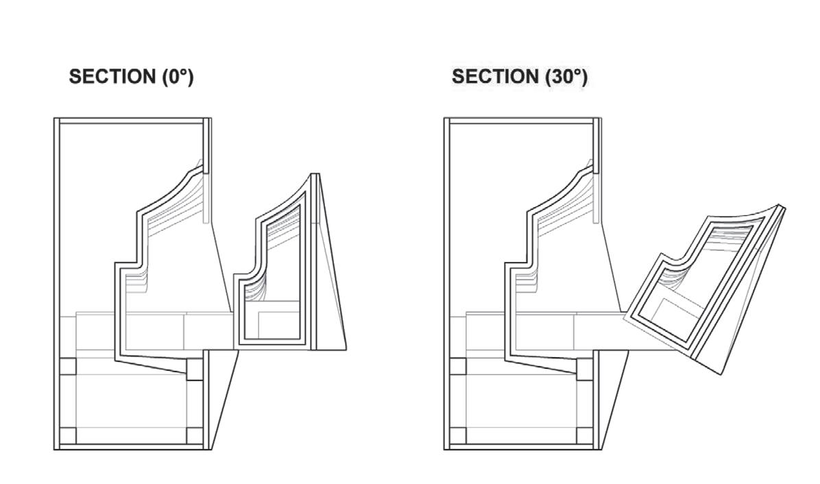
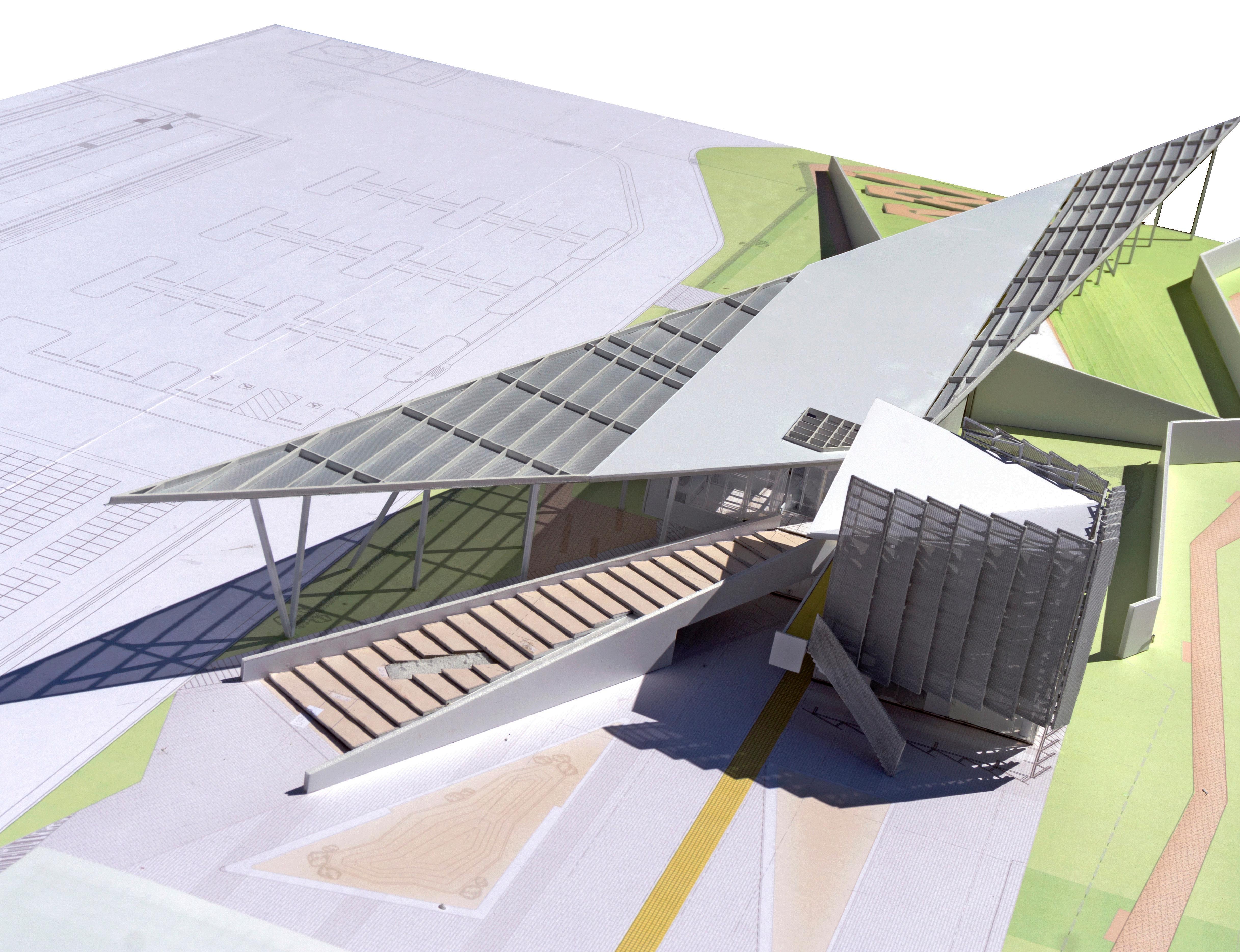
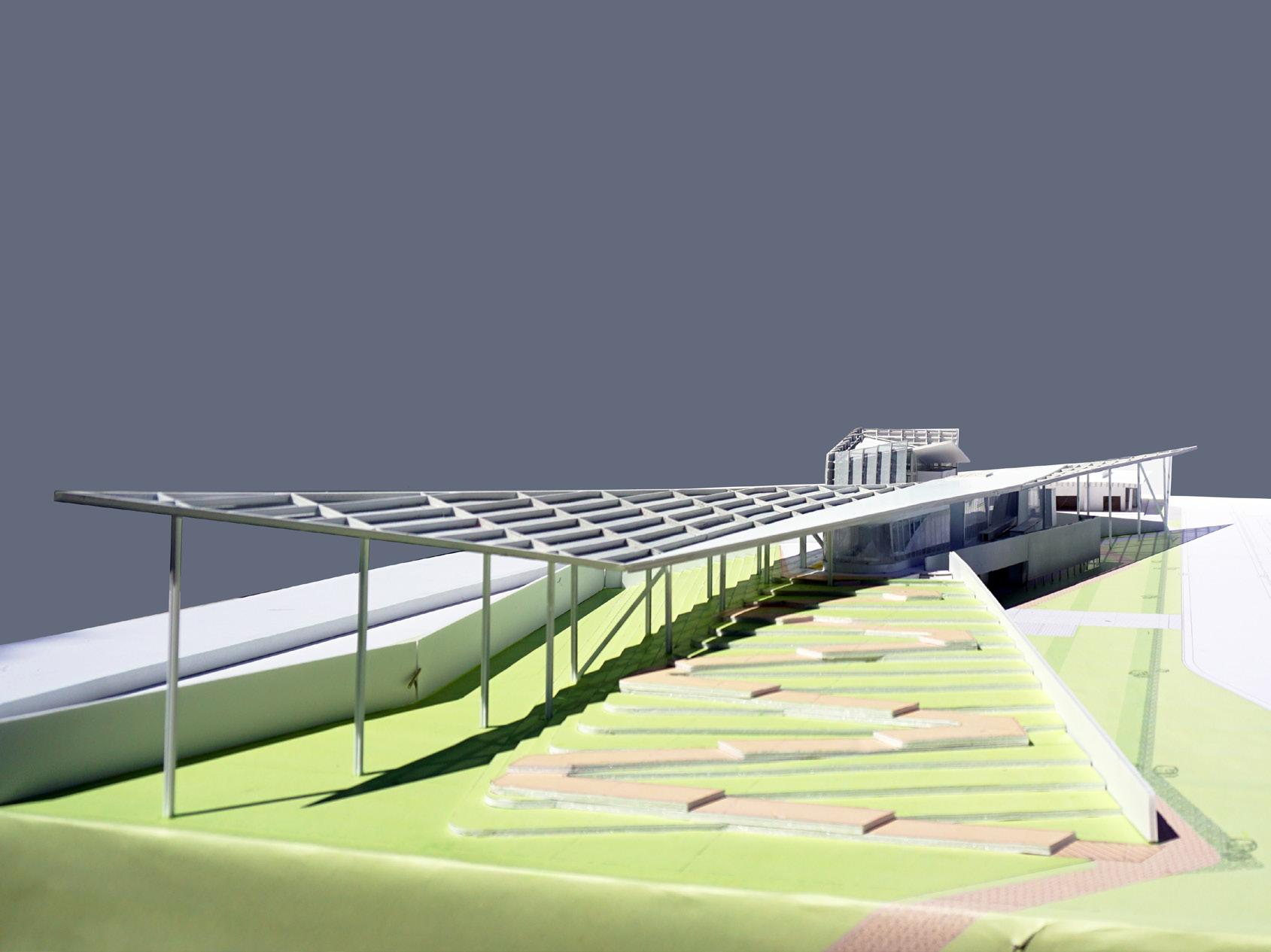
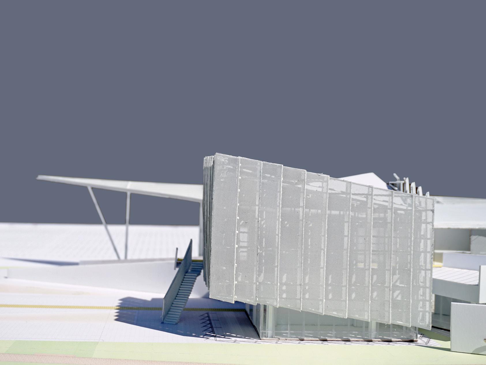
THE SEXY CHAIR
SCI-Arc | Fall 2018 Instructor - Dwayne Oyler
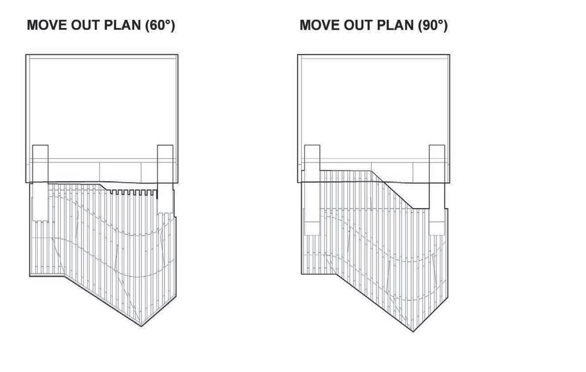
This project explore new possibilities by combining two mobile modes.
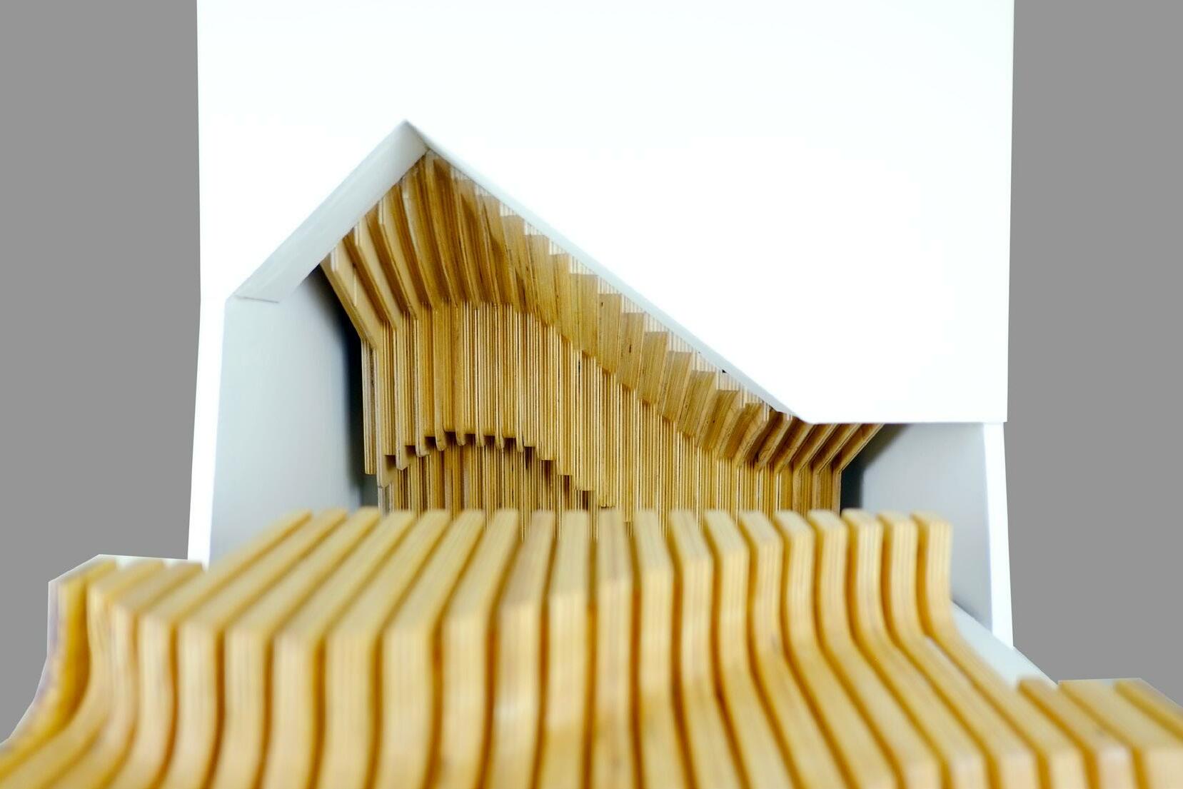
The dark wood chair is drawn slowly from the smooth white wall, and then rotated so that people can sit on its surface. The contrast surprises people and makes it interesting. This is a design from details to the whole, the appearance of the chair changes with our mobile system, which let the details generate the design rather than the details assist the design.
52
07
|
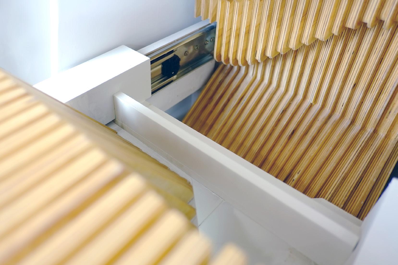
WORKING MODEL
Slide and rotate mechanisms of movable chairs are combined in this project which is embedded in the wall. Slide and ball bearing are directly connected by bolt. The design focuses on how to hide the hardware and to maintain its continuity and integrity. We cover slide with a ‘U’ Shape to make this mechanism a whole. The chair that comes off the wall are seen as part of the wall, and this can be seen in the curves of the wood that are nested within each other.
54 55
56
57 | DETAILS & DETAILS
WORKING MODEL |
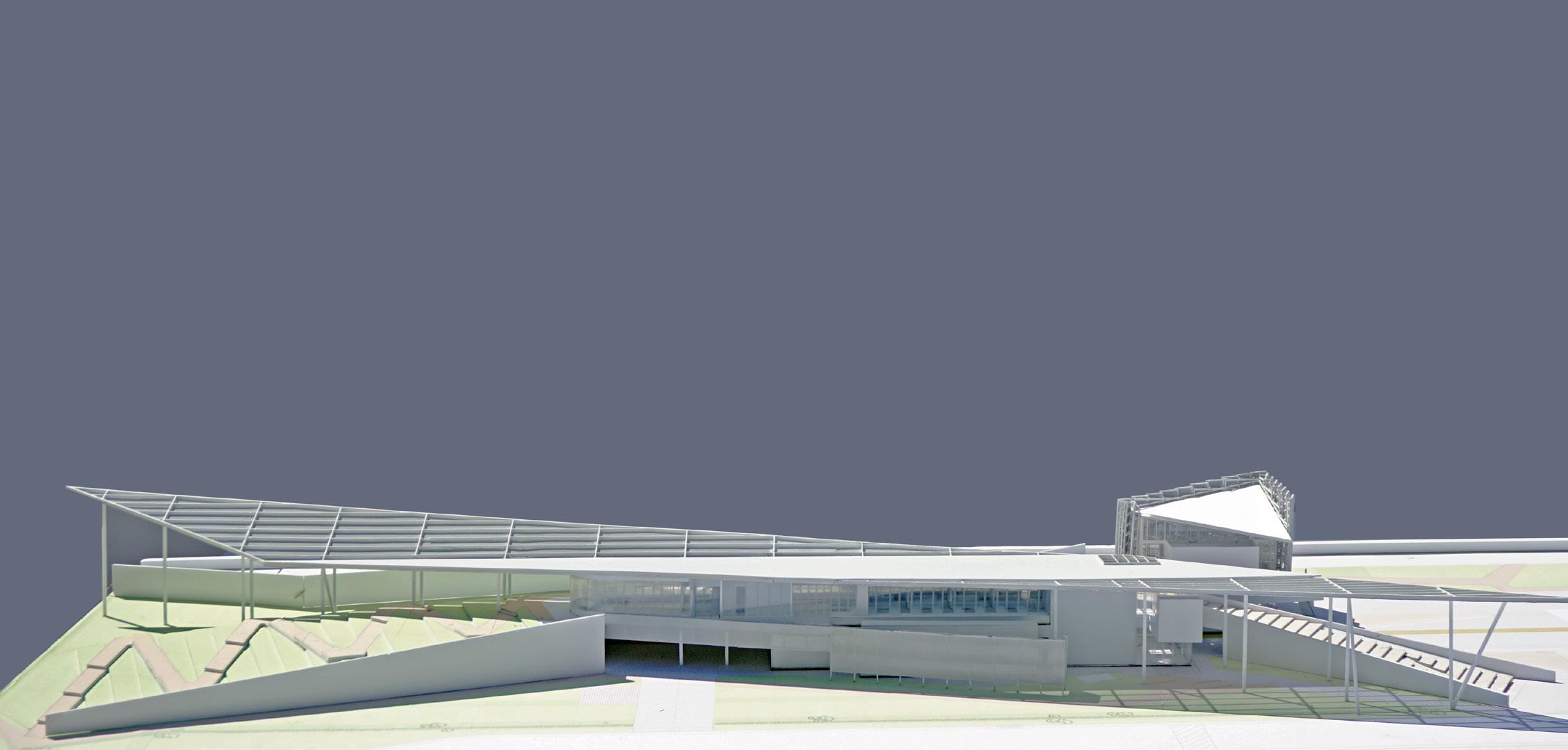
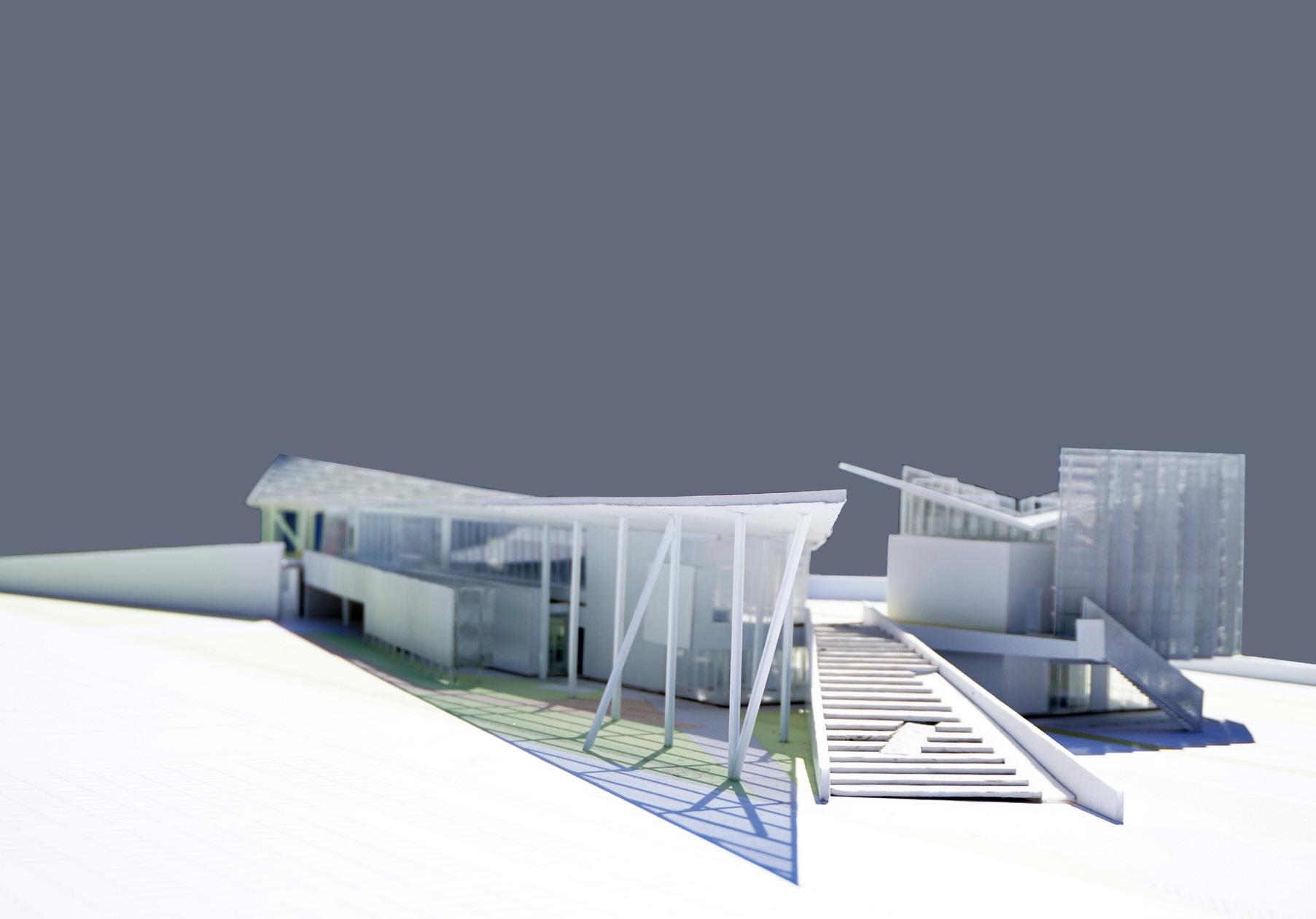
LA/G WRP PERSONNEL BUILDINGS
Internship | Lehrer Architects (Los Angeles) 2019 08 58 59
PHYSICAL MODEL |
60
61
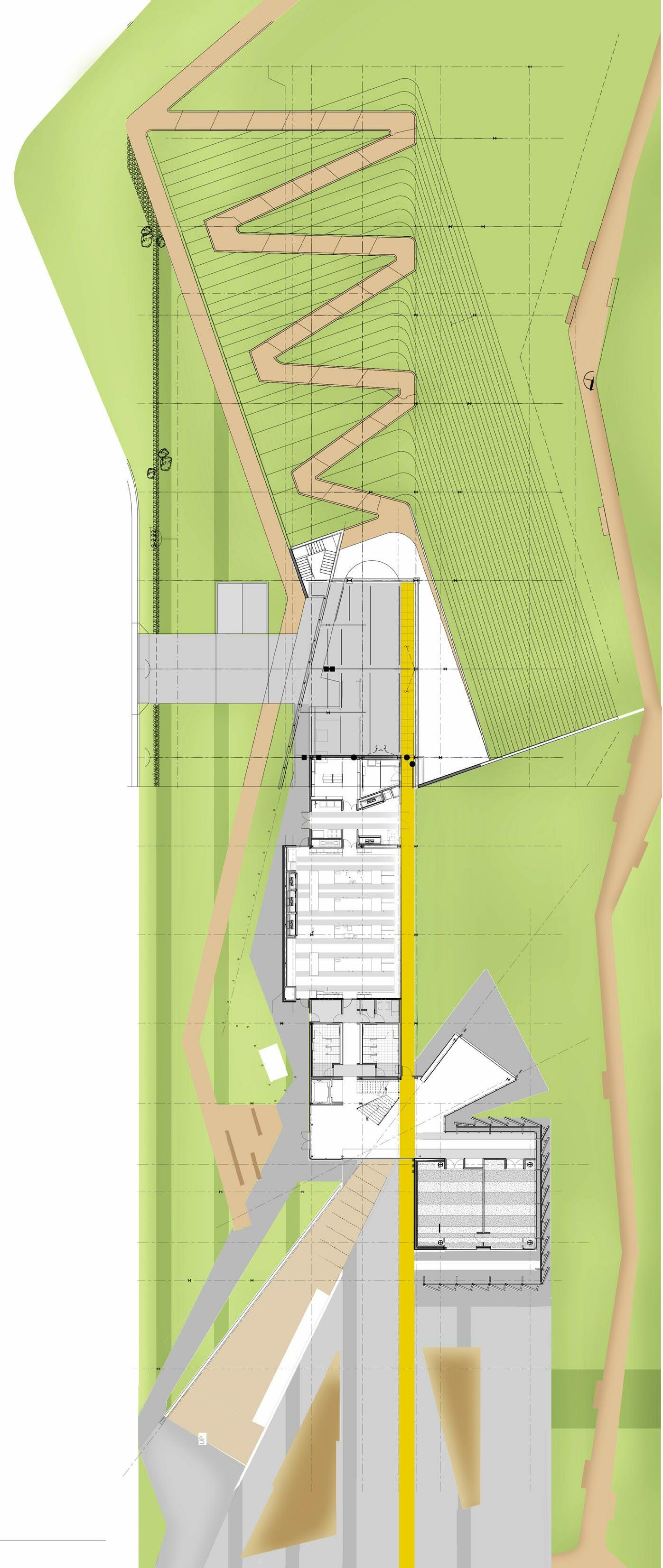
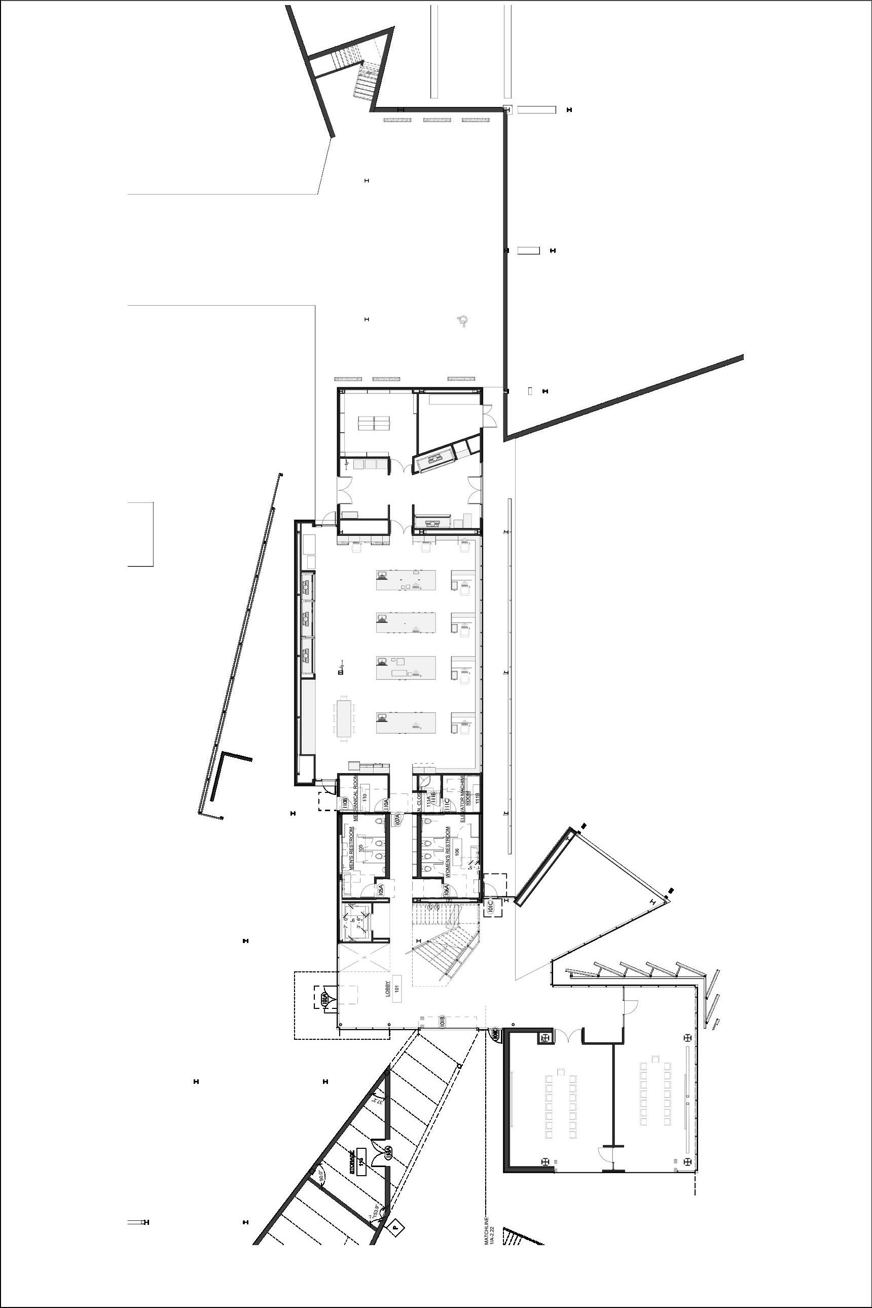
ARCHITECTURAL
| Site Plan 63 Building 2
Building 2
finish plan
DRAWINGS
Enlarged Lobby and Restroom floor plan
Floor
INCREMENTAL HOUSING
AS YOU GO’
Sushant School of Art and Architecture | Thesis 2016
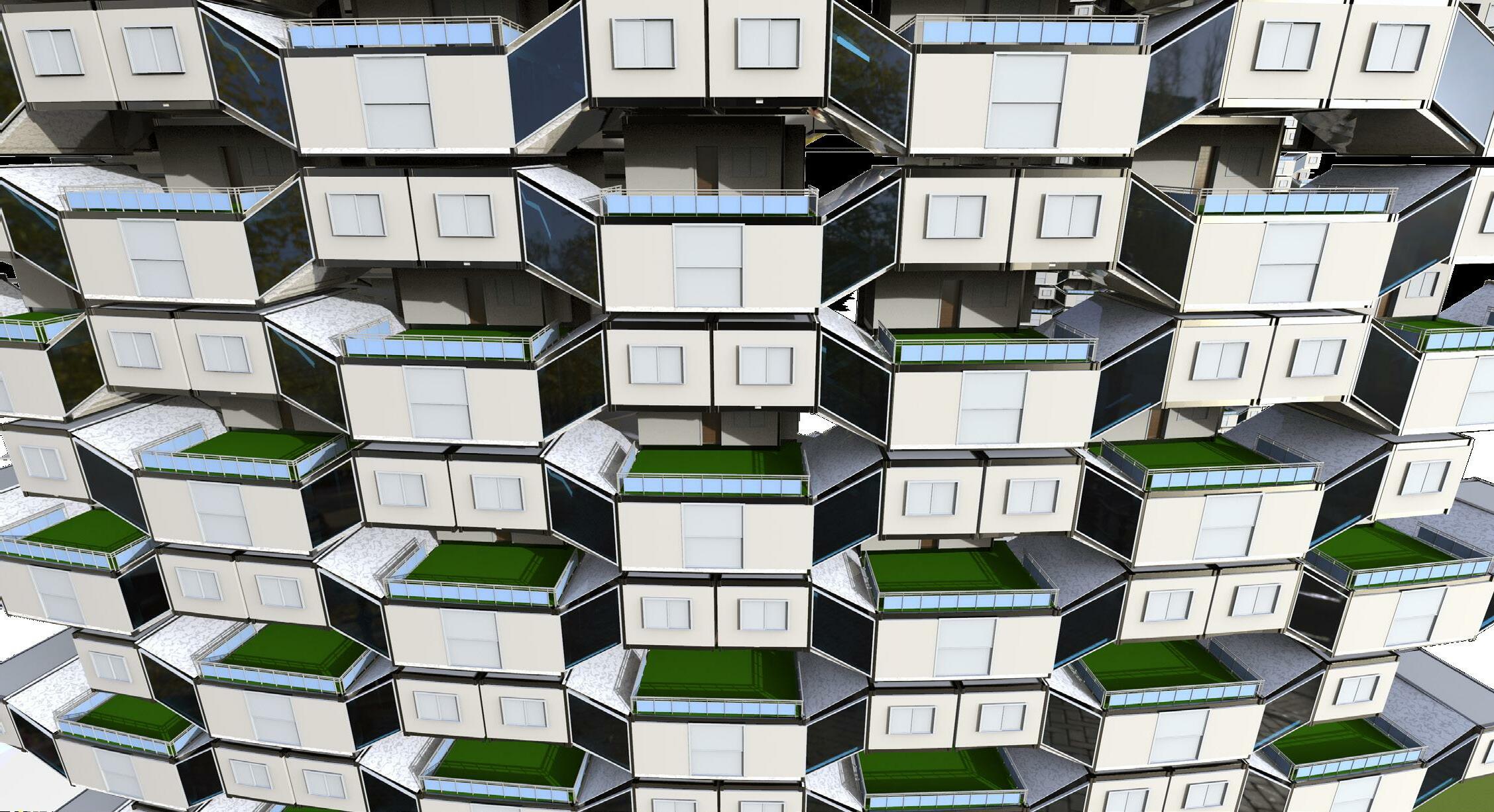
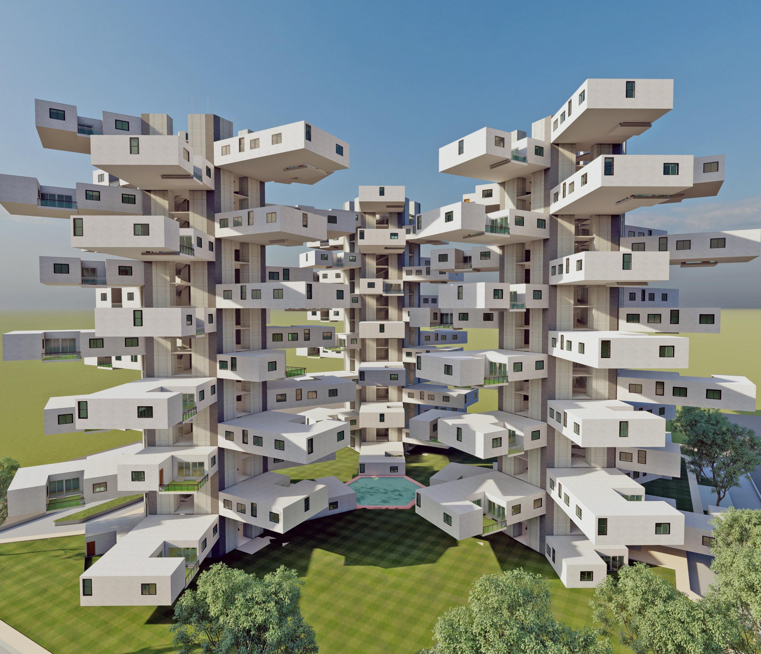
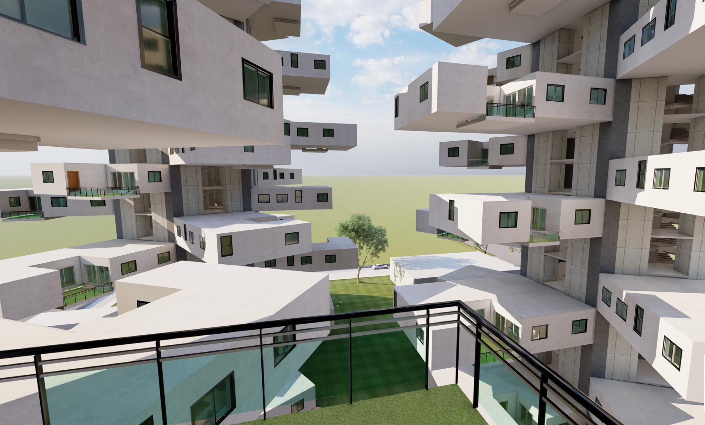
The project explores the idea of incremental housing as a solution to rapid urbanization and demands of the society. The ambition is a new alternative highrise residential typology, in which its inhabitants are given unique units and allocations in accordance to specific zoning strategy within a tower structure, thus creating a phenomenal living experience through bonding and acquiring needs by each and every single individual. It is a reinterpretation of the balance between generosity and specificity aiming at formulating an extraordinary democratic living concept. The design process is unique and could be developed as a model to tackle rapid urban growth in cities.
64
‘PAY
09
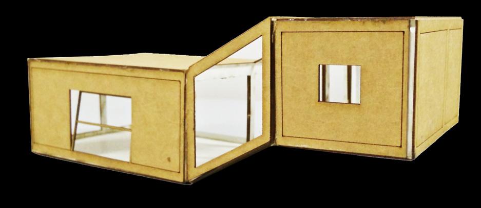
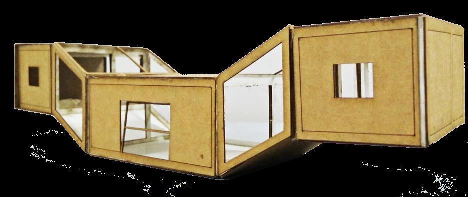
INDIVIDUAL UNIT WORKING |
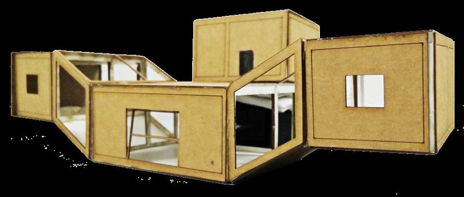
The proposal is a plug-in system where the modules when assembled create a living unit which can be moved from one place to the other. This is specially favorable for the working class population in metropolitan cities.
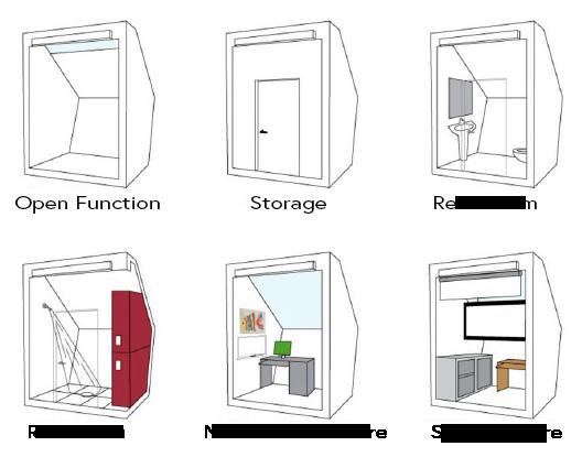
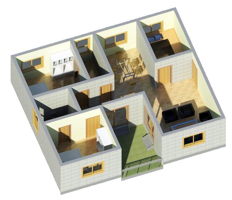
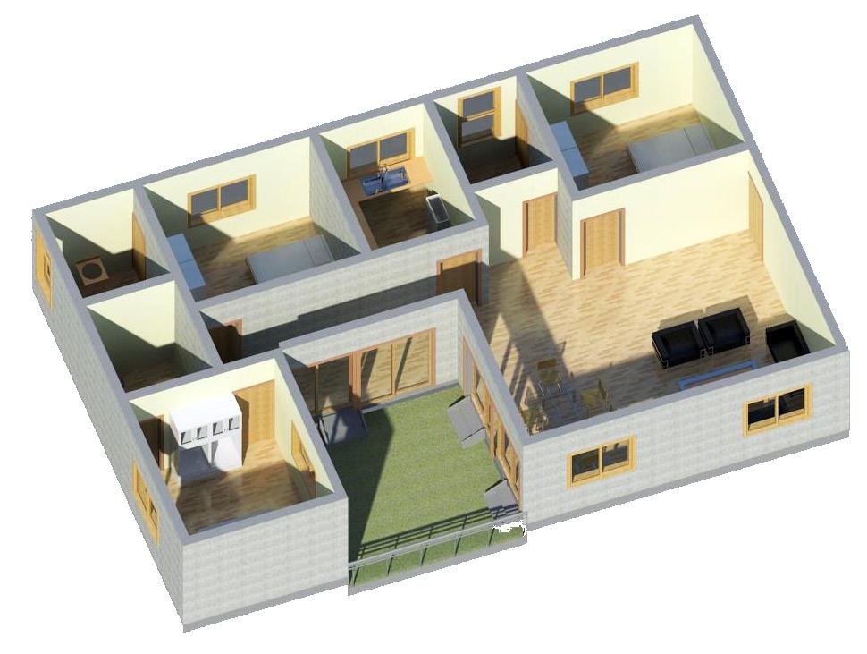
Today, the ideology of group housing is changing. In this project, an attempt is made to use the traditional courtyard system in a contemporary way. The central courtyard acts as an interactive zone/family zone.
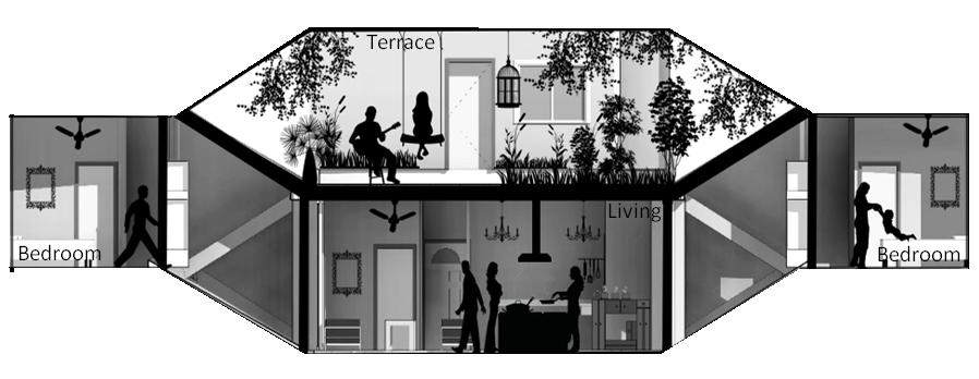
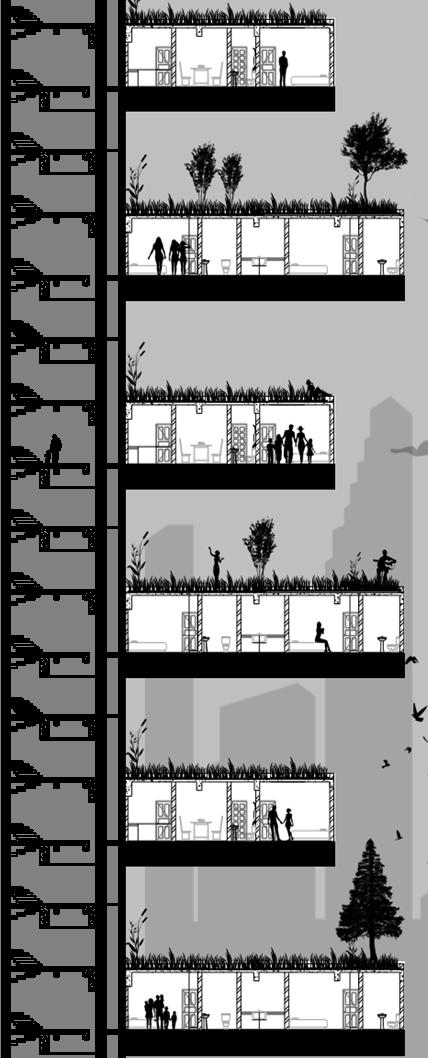
The section demonstrates the various addon modules which can be incorporated in the module as the requirements change or taste demands.
66
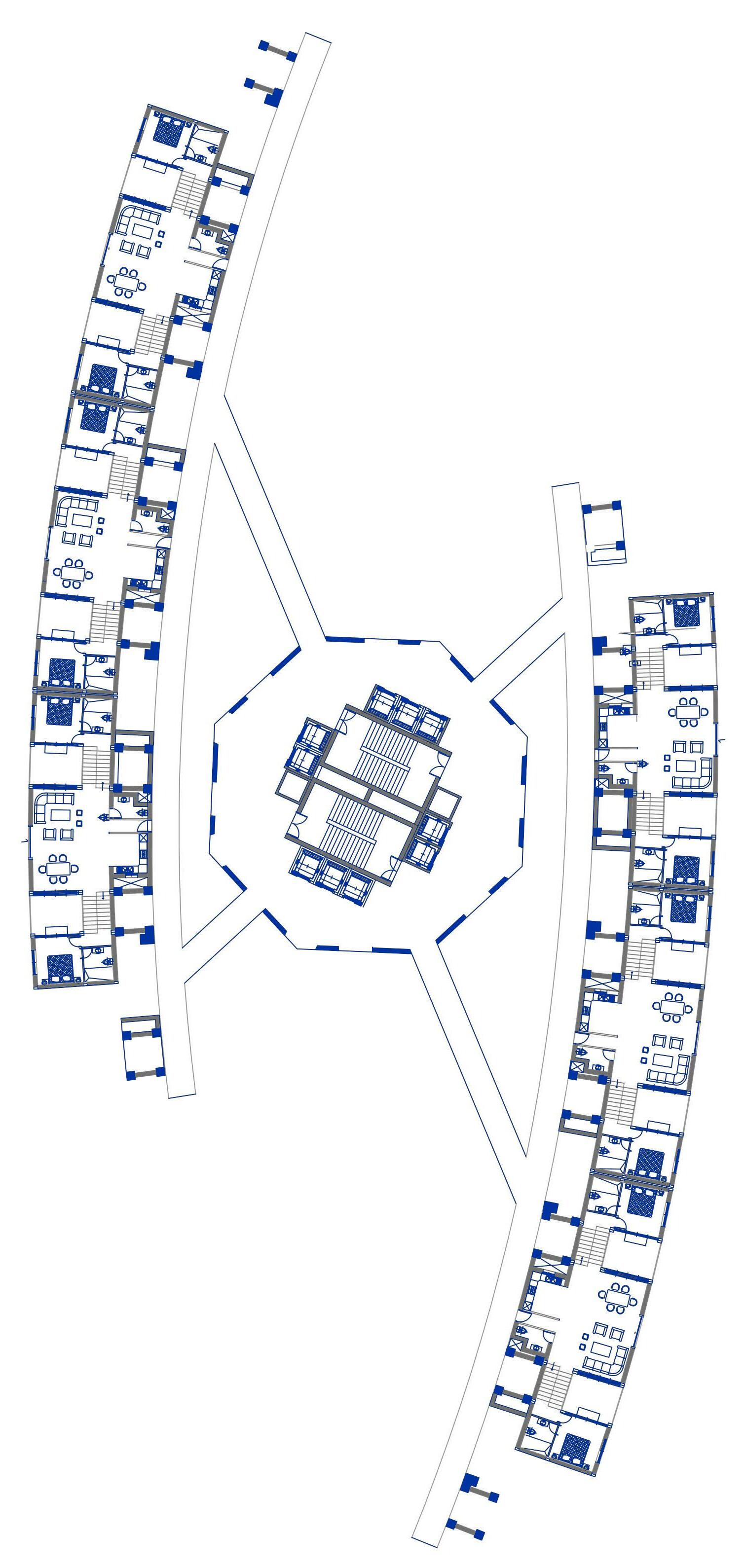
One Bedroom Apartment
Two Bedroom Apartment
Three Bedroom Apartment
Typical Floor Plan
The structure of the building is not affected by the plugging in and out of the apartments. The structure of each module of a unit is put together using rectangular hollow steel sections and other contemporary materials. Constructions cranes can be proposed as a permanent part of the building, thus adding a new room or replace parts that had worked out with a better product.
68
69 |
PLANS |
WORKING
THE COURTYARD HOUSE
Sushant School of Art and Architecture | Fall 2015
The aim is to develop a Mixed Use complex including residential, commercial and retail zones based upon the study of site on the factors of growing need for commercial spaces in nearby areas which fail to cater to the growing population needs. Each individual unit in the housing tower is unique in itself because of its placement strategies. The design is proposed such that people living in an apartment also get the comfort, luxury and feeling of a bungalow in a highly chaotic city such as New Delhi. The design aims to uplift the traditional courtyard system and contemporarise it as per modern needs and demands.
70 10
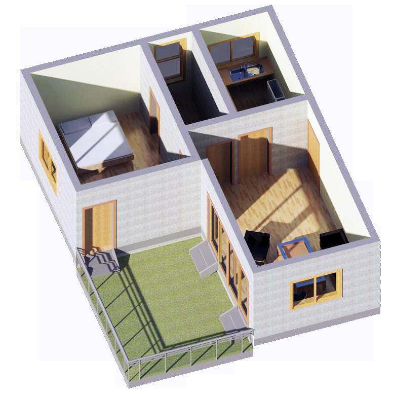
INDIVIDUAL UNIT |
The towers are designed in such a way that all circulations are centralized and each house acts like a villa. The idea is to use the traditional courtyard system in a unique way. Each apartment unit is cantilevered from the central core tower. The design of the structure allows for natural light and ventilation, with no obstructions in views
72
One Bedroom Apartment
Three Bedroom Apartment
Two Bedroom Apartment
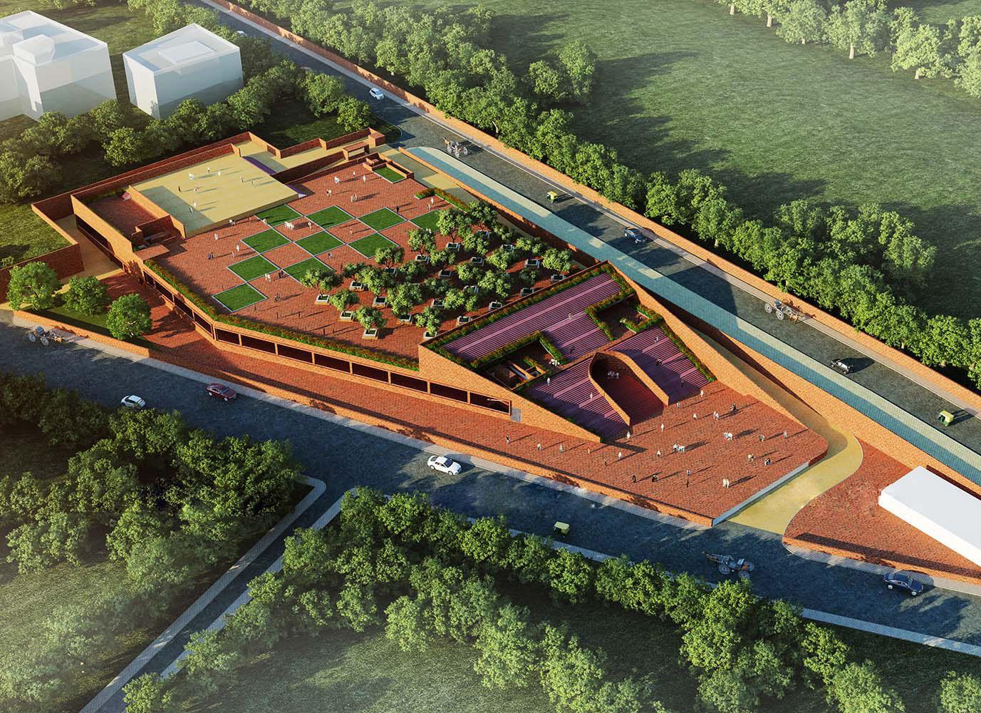
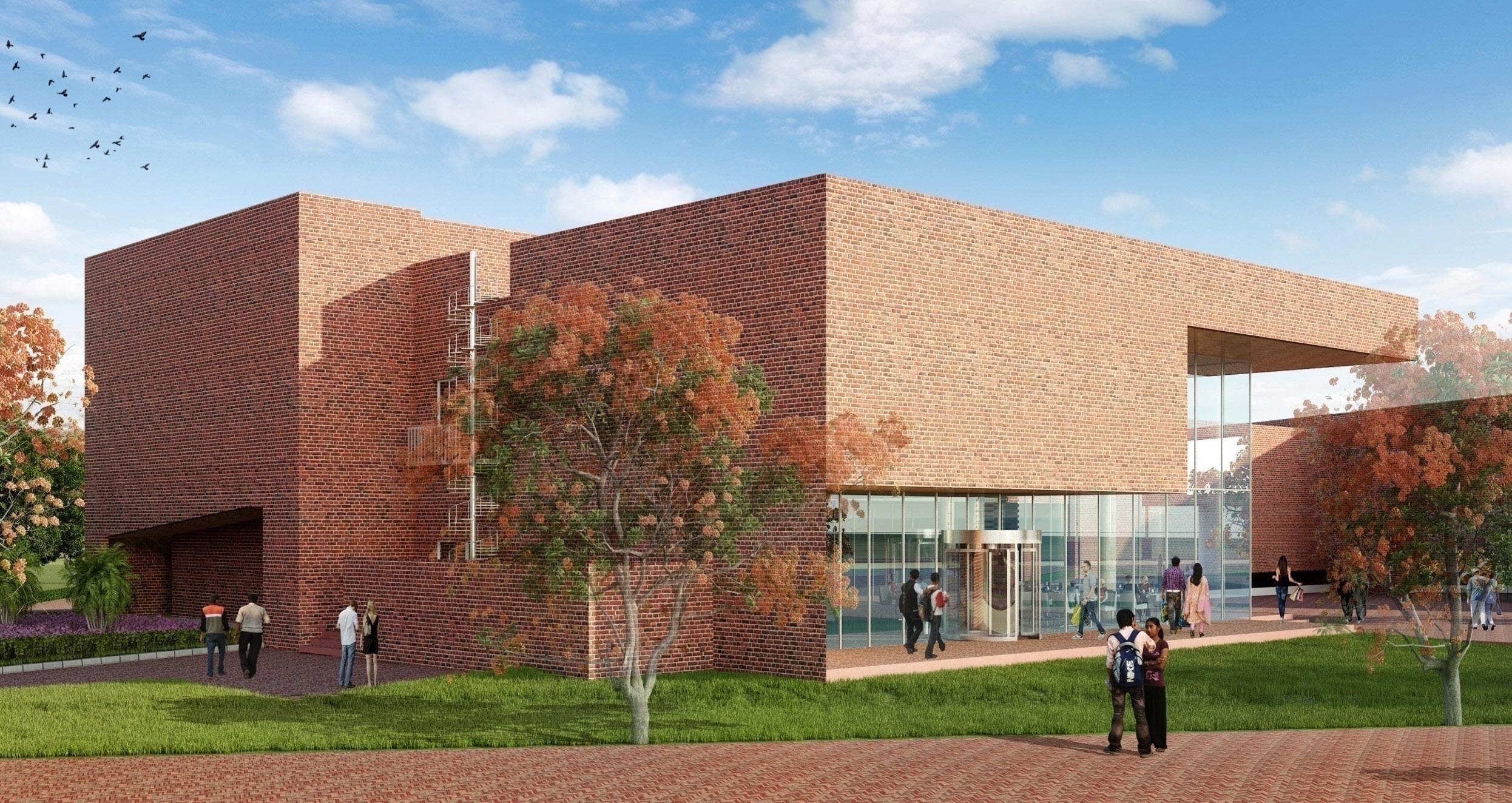
HERITAGE WALK, HUSSAINABAD
Internship at Archohm Consults, New Delhi, 2017
Heritage Walk- Hussainabad, Lucknow, India, is a heritage city that presents a multi-layered pastvestiges of which still route contemporary life . It has a specific set of challenges in its urban renewal programme.
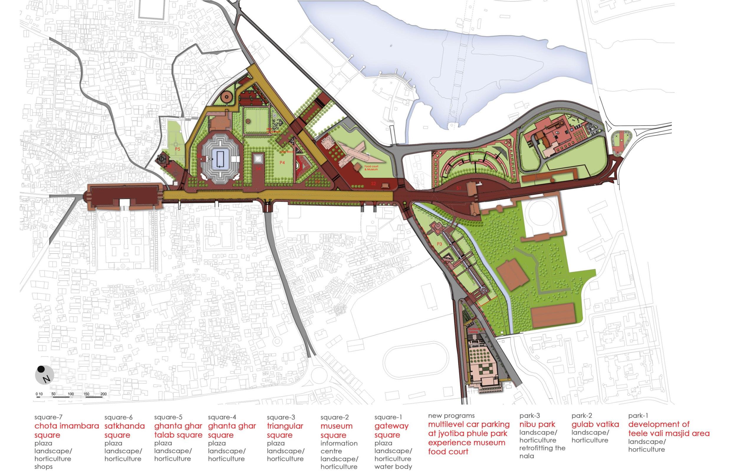
The comprehensive development has been proposed along a clear 1.3 kilometer linear stretch that has at one end-the Chota Imambara, at the other-the Bada Imambara and a series of monuments dotting the in-between.
74 10
11 75
MASTERPLAN |

76
77
Museum Building
Museum Building
FLOOR PLANS |
78 2. ALL DIMENSIONS GIVEN IN THIS DRAWING ARE IN MILLIMETERS 3. ALL DIMENSIONS TO BE VERIFIED ON SITE AND APPROVED BY SITE ENGINEER. IMMEDIATELY BE BROUGHT TO NOTICE OF THE ARCHITECT. AND ELECTRICAL DRAWINGS. THE SITE SUPERVISOR AND THE ARCHITECT. ALL REMAINING ARE RELATIVE TO THIS LEVEL. DRAWING TITLE DATE SCALE PROJECT NO. PROJECT CLIENT DRG.No. pocket-a, 30-d siddhartha extension INTEGRATED DEVELOPMENT OLD LUCKNOW (HUSSAINABAD LUCKNOW DEVELOPMENT AUTHORITY MAIN BUILDING GROUND FLOOR PLAN A-HHZ-MB-01-01 WORKING DRAWING 03-02-2017 AS/DWG AO-15-016 R.F.L. = ROAD FINISH LEVEL T.S.L. = F.F.L. = L.F.L. = LANDSCAPE LEVEL FINISH LEVEL BOTTOM OF FALSE CEILING LEVEL TOP OF FINISH LEVEL NO. DATE DESCRIPTION SCALE :1:400 - 1 GROUND FLOOR PLAN X01 Y01 X02 X03 X04 X06 X07 X08 X09 X10 X11 Y02 Y03 Y04 A01 A03 A05 A02 A04 A06 A07 A08 A10 A11 B01 B02 B03 B04 LOWERTOUPRAMPFIRST LVLFLOOR LIFT LVL +300 LVL +150 LVL +150 LVL +150 LVL +150 ROOM HVAC MASJID VIEW GALLERY UP LVL +300 X05 X12 X13 X14 3800 8000 3800 A09 4800 6000 4800 8000 6000 6000 6000 3570 16895 6605 6000 6000 2225 GUARD CONTROL 4'4131'3'-UP A00 A01' A05' A06' A10' 1755 3175 5275 UP TO (F)TOILET (M)TOILET SHOP UP TO (H)- SHAFT LOWERTOUPFIRSTLVLFLOOR 1. DO NOT SCALE THE DRAWING, FOLLOW ONLY FIGURED DIMENSIONS. 2. ALL DIMENSIONS GIVEN IN THIS DRAWING ARE IN MILLIMETERS METERS UNLESS NOTED OTHERWISE. SITE ENGINEER. 5. ALL DRAWINGS SHOULD BE READ IN CONJUNCTION WITH OTHER RELEVANT ARCHITECTURAL, STRUCTURAL, PLUMBING, MECHANICAL AND ELECTRICAL DRAWINGS. 6. THE ± REFERS TO LEVEL ESTABLISHED AT SITE IN PRESENCE ARE RELATIVE TO THIS LEVEL. NOTES DRAWING TITLE PROJECT CLIENT PLUMBING CONSULTANT CONSULTANTS STRUCTURAL CONSULTANT INTEGRATED DEVELOPMENT OLD LUCKNOW (HUSSAINABAD LUCKNOW DEVELOPMENT AUTHORITY MAIN BUILDING LOWER FIRST FLOOR PLAN A-HHZ-MB-01-02 WORKING DRAWING D.A. TK S.G AS/DWG AO-15-016 R.F.L. = ROAD FINISH LEVEL T.S.L. = T.P.L = TOP OF PARAPET LEVEL F.F.L. FIRST FLOOR FINISH LEVEL L.F.L. LANDSCAPE LEVEL TOP OF SLAB LEVEL M.F.L = MEMBER FINISH LEVEL NO. DATE DESCRIPTIONLOWER FIRST FLOOR PLAN CUTOUT (DOUBLE HEIGHT) ELECTRICAL UP DN MASJID VIEW GALLERY LEVLE+5300 DN LIFT SHAFT RAMP DN SHAFT RAMP DN RAMP DN LVL +3300 LVL +3600 X01 Y01 X02 X03 X04 X06 X07 X08 X09 X10 X11 Y02 Y03 Y04 A01 A03 A05 A02 A04 A06 A07 A08 A10 A11 B01 B02 B03 B04 X05 X12 X13 X14 10000 10000 7000 7000 7000 7000 7000 7000 7000 10000 10000 10000 10000 1665 14350 3800 8000 3800 A09 4800 6000 4800 5805 6000 6000 6000 3570 16895 6605 6000 6000 2225 4'4132'1'3'25'5A00 A01' A05' A06' A10' 5275 1755 3175 2195 3385 SHAFT SHAFT
Museum - Ground Floor Plan Museum - First Floor Plan 79 1. DO NOT SCALE THE DRAWING, FOLLOW ONLY FIGURED DIMENSIONS. METERS UNLESS NOTED OTHERWISE. SITE ENGINEER. 4. ANY DISCREPANCY OR AMBIGUITY IN THE DRAWINGS SHOULD 5. ALL DRAWINGS SHOULD BE READ IN CONJUNCTION WITH OTHER RELEVANT ARCHITECTURAL, STRUCTURAL, PLUMBING, MECHANICAL 6. THE ± REFERS TO LEVEL ESTABLISHED AT SITE IN PRESENCE ARE RELATIVE TO THIS LEVEL. NOTES PROJECT CLIENT CONSULTANT CONSULTANTS LIMRA INTEGRATED DEVELOPMENT OLD LUCKNOW (HUSSAINABAD LUCKNOW DEVELOPMENT AUTHORITY MAIN BUILDING P.F.L. = PAVEMENT FINISH LEVEL G.F.L. = TOP OF PARAPET LEVEL FIRST FLOOR FINISH LEVEL P.F.L. = PAVEMENT FINISH LEVEL TOP OF SLAB LEVEL M.F.L = MEMBER FINISH LEVEL NO. DATE DESCRIPTION LVL +7700 LVL +7900 GALLERY CAFETERIA LOBBY UP CAFETERIA UP UP SHAFT LIFT LIFT TO TERRACE LEVEL RAMP UP TO LEVEL+6900 RAMP UP RAMP UP TO LEVEL+7900 RCC WALL AS/STR. LVL +6900 X01 Y01 X02 X03 X04 X06 X07 X08 X09 X10 X11 Y02 Y03 Y04 A01 A03 A05 A02 A04 A06 A07 A08 A10 A11 B01 B02 B03 B04X05 X12 X13 X14 10000 10000 10270 3800 8000 3800 A09 4800 6000 4800 5805 6000 6000 6000 3570 16895 6605 6000 6000 2225 ELECTRICAL LVL +5400 132'1'25'5A00 A01' A05' A06' A10' 2195 3385 1755 3175 5275 DN TO GROUND FLOOR SHAFT (F)- TOILET SER. (M)CUTOUT IN SLAB CUTOUT Museum - Second Floor Plan
80 1. DO NOT SCALE THE DRAWING, FOLLOW ONLY FIGURED DIMENSIONS. 2. ALL DIMENSIONS GIVEN IN THIS DRAWING ARE IN MILLIMETERS AND METERS UNLESS NOTED OTHERWISE. 3. ALL DIMENSIONS TO BE VERIFIED ON SITE AND APPROVED BY THE SITE ENGINEER. 4. ANY DISCREPANCY OR AMBIGUITY THE DRAWINGS SHOULD IMMEDIATELY BE BROUGHT TO NOTICE OF THE ARCHITECT. 5. ALL DRAWINGS SHOULD BE READ IN CONJUNCTION WITH OTHER RELEVANT ARCHITECTURAL, STRUCTURAL, PLUMBING, MECHANICAL AND ELECTRICAL DRAWINGS. 6. THE REFERS TO LEVEL ESTABLISHED AT SITE PRESENCE OF THE SITE SUPERVISOR AND THE ARCHITECT. ALL REMAINING LEVELS ARE RELATIVE TO THIS LEVEL. NOTES DRAWING TITLE DATE SCALE PROJECT NO. CHECKED BY DESIGN BY PROJECT CLIENT DRG.No. DRAWN BY c-28c, sector-8, noida 201301 (up) 91 120 46 40 300 91 120 42 46 788 mail@archohm.com www.archohm.com ARCHITECTURE URBANISM CONSULTANT PLUMBING CONSULTANT pocket-a, 30-d siddhartha extension new delhi-110014, telefax-26344668 e-mail:- ssb_tec@yahoo.co.in &tec@bol.net.in TECHNO ENGINEERING CONSULTANTS STRUCTURAL CONSULTANT HVAC CONSULTANT INTEGRATED DEVELOPMENT OF OLD LUCKNOW (HUSSAINABAD AREA) LUCKNOW DEVELOPMENT AUTHORITY MAIN BUILDING SECTIONS A-HHZ-MB-03-01 WORKING DRAWING D.A. TK S.G 06-02-2017 AS/DWG AO-15-016 R0 NO. DATE DONE BY DESCRIPTION 300 6900 7900 GROUND LVL+300 LOWER FIRST LVL+3600 UPPER FIRST LVL+7900 LVL+6900 TOP OF TERRACE LVL+11300 1000 3400 6800 6900 800 GROUND LVL+300 LVL+6800 LVL+5300 TOP OF TERRACE LVL+11300 LVL+6900 LVL+7700 LVL +7700 LVL +5300 ROOMI GALLERY GALLERY RAMP UP TO LEVEL+6900 RAMP UP TO LEVEL+7700 LVL +6800 LVL +6900 TRUSS AS/STRUCTURE RCC. BEAM IN ELEVATION RCC. BEAM SLAB AS/STRUCTURE RCC. BEAM & SLAB AS/STRUCTURE LVL +300 X01 X02 X03 X04 X06 X07 X08 X09 X10 X11 X05 X12 X13 X14 SCALE :- 1:4001 SECTION AT- (1-1') SCALE :- 1:4002 SECTION AT- (2-2') X01 X02 X03 X04 X06 X07 X08 X09 X10 X11 X05 X12 X13 X14 RCC. BEAM SLAB AS/STRUCTURE RCC. BEAM IN ELEVATION TRUSS IN ELEVATION RAMP UP TO TERRACE LEVEL DISPLAY GALLERY STORE LVL +5300 ROOMI GALLERY LVL +3600 LVL +7700 GALLERY AV ROOM LVL +6200 LVL +6800 LVL +7900 7700 7900 14300 200 3400 GROUND LVL+300 LOWER FIRST LVL+3600 LVL+5300 LVL+6800 LVL+7700 TOP OF TERRACE LVL+11300 UPPER FIRST LVL+7900 X01 X02 X03 X04 X06 X07 X08 X09 X10 X11 X05 X12 X13 X14 5300 7900 1500 3400 GROUND LVL+300 LOWER FIRST LVL+3600 LVL+5300 LVL+6800 LVL+7700 TOP OF TERRACE LVL+11300 UPPER FIRST LVL+7900 LVL +5300 ROOMI GALLERY TRUSS IN ELEVATION RCC. BEAM SLAB AS/STRUCTURE LVL +3600 SOUVENIR SHOP RAMP UP TO LEVEL+5300 RAMP UP TO LEVEL+7900 LVL +7700 GALLERY LVL +300 LVL +300 SCALE :- 1:4003 SECTION AT- (3-3') A01 A03 A05 A02 A04 A07 A08 A10 A11 A09 MODEL DISPLAY AREA LVL +300 LVL +300 SERVICE STAIRCASE MASJID VIEW GALLERY ENTRANCE LOBBY LVL +3600 STORE 5400 LVL +5400 LVL +6900 RAMP RAMP AV ROOM KITCHEN LVL +7900 CAFETERIA SCALE 1:4004 SECTION AT- (4-4') A01 A03 A05 A02 A04 A07 A08 A10 A11 A09 SCALE 1:4004 SECTION AT- (5-5') MASJID VIEW GALLERY LVL +5400 LVL +6900 LVL +300 MODEL DISPLAY AREA LVL +300 RAMP LVL +3600 DISPLAY GALLERY LVL +3600 RAMP LVL +7900 CAFETERIA LOBBY CAFETERIA LVL +7900 300 6900 7900 1000 3400 GROUND LVL+300 LOWER FIRST LVL+3600 UPPER FIRST LVL+7900 LVL+6900 TOP OF TERRACE LVL+11300 LVL+1700 CONTROL ROOM (F)- TOILET (M)- TOILET (H)TOILET CLOAK TICKET 3000 14300 3000 14300 3000 14300 3000 PARAPET WALL LVL+14300 PARAPET WALL LVL+14300 PARAPET WALL LVL+14300 PARAPET WALL LVL+14300 PARAPET WALL LVL+14300 A05' A06' A06 A05' A06' A06
81 ELEVATION -A ELEVATION -B ELEVATION -D ELEVATION -C ELEVATION -E 6800 7900 11300 900 3400 GROUND LVL+300 LOWER FIRST LVL+3600 LVL+5300 LVL+6800 LVL+7700 TOP OF TERRACE LVL+11300 UPPER FIRST LVL+7900 6800 7900 11300 900 3400 GROUND LVL+300 LOWER FIRST LVL+3600 LVL+5300 LVL+6800 LVL+7700 TOP OF TERRACE LVL+11300 UPPER FIRST LVL+7900 6800 7900 11300 900 3400 GROUND LVL+300 LOWER FIRST LVL+3600 LVL+5300 LVL+6800 LVL+7700 TOP OF TERRACE LVL+11300 UPPER FIRST LVL+7900 300 3600 5300 7700 1700 1500 200 GROUND LVL+300 LOWER FIRST LVL+3600 LVL+5300 LVL+6800 LVL+7700 TOP OF TERRACE LVL+11300 UPPER FIRST LVL+7900 6800 11300 900 GROUND LVL+300 LOWER FIRST LVL+3600 LVL+5300 LVL+6800 LVL+7700 TOP OF TERRACE LVL+11300 UPPER FIRST LVL+7900 SCALE 1:4001 ELEVATIONS PARAPET WALL LVL+14300 PARAPET WALL LVL+14300 PARAPET WALL LVL+14300 PARAPET WALL LVL+14300 PARAPET WALL LVL+14300 | ELEVATIONS
SECTIONS |
DEEPAK AGRAWAL
deepak225@gmail.com
