6 minute read
Self-drilling Micropiles
By Matt Sotirin, P.E., and Marc Mastrantuono, P.E., Ischebeck USA
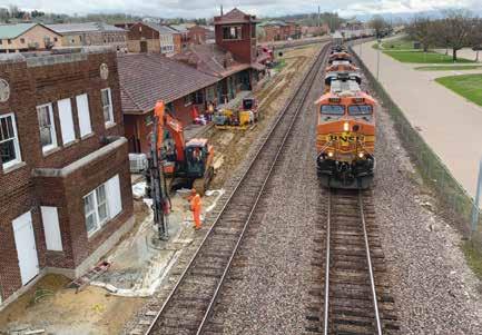
This article was originally published in DFI’s bi-monthly member magazine, Deep Foundations, Sept/Oct 2022 issue. DFI is an international technical association of firms and individuals in the deep foundations and related industries. To join DFI and receive the magazine, go to www.dfi.org. The Santa Fe train station and passenger rail platform were constructed in the downtown district of Fort Madison, Iowa, over a century ago. This landmark building and rail platform were in need of major renovations and rehabilitation in order to restore the site to a functioning railway train station. A multitude of key players from various public and private parties were involved in the design and construction of this project site.
Part of the project consisted of constructing the passenger platform. The original design included helical piles to provide foundational support for the platform. Challenges occurred during construction due to the presence of an obstruction in the form of a poured concrete slab in the immediate area where the helical piles were to be installed. The contractor worked with the engineer of record and other consulting parties to value engineer the helical pile design and utilize self-drilling micropiles as a replacement to the specified helical pile system.
HOLLOW BAR OPTION
The contractor utilized a threaded hollow bar micropile system. The hollow bar simultaneously acts as the drilling rod, grout injection tube and structural reinforcement for the micropile. These systems can be used in most soil types, including unstable soils, without the need for temporary casing. With the use of a sacrificial drill bit, the hollow bar is drilled, with additional bars being added using couplers, until the desired micropile depth is reached. A structural cement grout is then injected through the hollow bar that produces a grout body that encapsulates the structural reinforcement (hollow bar) and bonds with the surrounding soil. The pumping of the grout also further improves the surrounding soils. This provides necessary skin friction for the pile to resist both compressive and tensile forces. DESIGN The original helical pile design consisted of 80 locations spanning the length of the platform, requiring a working load capacity of 45 kip (200 kN). The general contractor encountered a concrete obstruction, at approximately five feet (1.5 metres) of depth adjacent to the rail tracks, underneath the ballast rock. The concrete slab was not shown on any of the original construction plans for the rail depot nor was it shown in the soils report. The initial solution was to core a hole through the concrete slab at each of the 80 helical pile locations. However, this solution was going to be a significant added cost to the project. The foundation contractor began looking for alternative options that would be cost-effective while still offering the performance and load carrying characteristics required by the specification.
A piece of the concrete obstruction was exposed and broken up to check for the type of reinforcement. The slab contained a wire mesh reinforcing system. This aided the scenario for a successful hollow bar micropile design, as the drill bits used are capable of drilling through wire mesh.
The next step was to determine structural capacity and geotechnical capacity of a hollow bar system to ensure proper hollow bar selection and micropile length.
Utilizing 45kip (200 kN) as the design load, the calculations for selecting a steel reinforcement yielded a 40 mm (1.6 in) outer diameter, 20 mm (0.79 in) inner diameter hollow bar, which exceeded both the working load (one time the design load) and testing load (two times the design load) requirements.
The geotechnical report indicated loose to very loose mixed soils with single digit Standard Penetration Test blows/ foot. At approximately 25 ft (7.62 m) depth, a harder layer of sandy clay was found. For the geotechnical capacity of the micropile, the first 25 ft (7.62 m) were treated as an unbonded zone that had no contribution to the pile capacity.
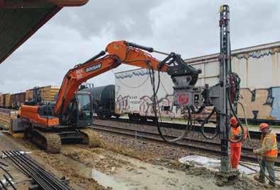
Installation work underway near active rail operations. The contractor installed 80 micropiles on the project.

Because the boring log was terminated at 31.5 ft (10.5 m), the assumption was that the soil strata below would be representative of the sandy clay material for preliminary design purposes. A pile length of 79 ft (24 m) was estimated.
The hollow bar micropiles were a direct replacement to the helical pier schedule and location. Because there was a lack of soil data below 31 ft (9.5 m), the final micropile design (pile length) would be determined from preproduction load testing to confirm a final micropile design.
LOAD TESTING Once the location, bar selection and preliminary micropile length were developed and approved, the contractor worked with the engineer of record and the hollow bar manufacturer’s technical consultant to develop a preproduction load testing program to satisfy specification requirements and determine the actual required micropile length.
The load test consisted of three preproduction piles that were installed to varying depths on site just west of the railway on the north end of the existing train depot. The purpose of the test was to verify the load requirements at the respective depths to establish a final production pile installation depth. Even though these micropiles were designed to be loaded in compression, a tension test was selected as it is a more cost-effective test procedure and helps determine the friction resistance of the pile, without the added benefit of end
bearing support. The micropiles were loaded to two times the design load of 45 kip (200 kN).
All three tests passed the criteria for the preproduction load testing program. This allowed the contractor to work with the engineer of record to reduce the pile lengths to 40 ft (12 m). The location for installing the test piles was approximately -10 ft (-3 m) in elevation from where the production piles were to be installed. To account for this additional unbonded zone, the final micropile length selected for use was 50 ft (15 m). PRODUCTION PILES After finalizing the micropile design based on load testing results, 80 50-foot (15-metre) hollow bar micropiles were installed per the micropile schedule and layout. The contractor was able to complete the installation of all 80 micropiles on time and meet the required construction schedule. By using hollow bar micropiles, the parties involved were able to provide a solution to the issues posed by the buried slab in a cost-effective manner, all while working next to an active railroad.
CONCLUSION The Santa Fe Depot Passenger Rail Platform required a unique solution to its foundational support problem. Initially the project was designed and specified with a helical pile system. After obstructive debris in the form of wire mesh reinforced concrete slab was found below grade, a hollow bar micropile system was selected as a cost-effective alternative to provide support for the rail platform.
After successful load testing and revised design considerations, 80 50-foot (15-metre) hollow bar micropiles were used along the rail line where the platform was to be installed. The contractor was able to install the system within the scope of the construction schedule and provide cost savings to the owner when compared to other solutions.
Matt Sotirin, P.E., is a geotechnical specialist at Ischebeck USA. He has extensive experience in the construction industry and works closely with consulting engineers and specialty contractors to provide geotechnical solutions for complex construction projects.
Marc Mastrantuono, P.E., is the geotechnical division manager at Ischebeck USA. He has over a decade of experience in specialty micropile design, installation, and manufacturing. He works with industry professionals to provide the best geotechnical solution and support. l

