6 minute read
Reducing the Labour Required for Emergency Preparedness
Computerized, centrally-managed emergency lighting systems lower maintenance costs and ease compliance with safety codes
In the interest of public safety, building and life safety codes for exit signs and emergency lights require that a building owner/manager conduct a functional test every month, conduct discharge tests annually and keep a log book of maintenance information. Complying with these standards using facility management personnel to cover a large building or multiple buildings can quickly add up to many hours of costly, qualified labour in order to manually inspect and test every individual unit and record the results. Thanks to new computerized emergency light monitoring systems, however, it is no longer necessary to incur the cost of labour-intensive testing. By implementing a centrally-controlled system, these tasks can be performed remotely, greatly reducing the need for labour.
EMERGENCY LIGHT MONITORING: HOW THE SYSTEM WORKS
A computerized emergency lighting system is a combination of a communication network and single point emergency light units located throughout a building or buildings. Each single point unit is an emergency lighting fixture that stands alone and includes its own rechargeable battery and charger equipment. When normal AC power fails, the unit turns on its emergency lamp until the power is restored or the battery discharges.
The monitoring system communicates using a centrallylocated server, which can be a computer or controller. The flexibility of the centralized system allows individual emergency light units to be assigned to groups that represent departments, floors or other logical divisions. The central controller can test and report on the status of all emergency lights in real time individually, in groups or system-wide. The network passes messages to and from the emergency units to instruct the units to perform a task, such as turning the light on or off, and to report back to the controller to give the unit’s status, for example, whether or not the lamp is working.
Computerized emergency lighting systems can use a variety of means to communicate, including a dedicated communication cable wired between every emergency light and wireless communication.
WIRED AND WIRELESS VERSIONS ELIMINATE INSTALLATION CONSTRAINTS
System design is entirely flexible, with both wired and wireless versions available. The wired system uses a dedicated cable network, making it ideal for areas where wireless communication is not possible. A wireless system that uses radio frequency (RF) communication and 900 MHz mesh networking technology can penetrate dense building materials, including masonry walls. With an RF system, an area controller acts as a web server, which can be set up to allow access to a remote computer.
A wireless system can greatly reduce installation costs, particularly in small sites, sites with multiple buildings or complex layouts, heritage locations, and in sites with complex IT networks where firewalls may have interfered with the cabled system. With new wireless options, installing an automated emergency lighting and exit sign monitoring system is now faster and easier than before.
SYSTEM AUTOMATION IS THE KEY TO INCREASED EFFICIENCY AND REDUCED LABOUR COSTS
With a remotely-managed computerized system, the building manager can see the real-time status of the entire emergency lighting and exit sign system, run system diagnostics,

Dust Collectors & Welding Exhaust Systems Clean Air for your School Environment

12200 - 1ST Avenue Richmond, B.C. Canada V7E 3M2 Ph: (604) 271-9222 • Fax: (604) 271-2156 Email: info@nu-techsystems.com Website: www.nu-techsystems.com
Gerald Fudge AMP NETCONNECT
Sales Engineer gfudge@tycoelectronics.com Tyco Electronics Canada Ltd. 1485 Lindsey Place Annacis Island Delta, BC CAN V3M 6V1 604-515-8949 tel 604-519-1477 fax 604-340-2605 cell www.ampnetconnect.com www.tycoelectronics.com


perform required monthly and annual functional tests, generate maintenance logs, run compliance reports and perform other system-critical functions quickly and easily, all from a central control unit. Compared to manual management, automated monitoring is more efficient, less costly and provides higher quality data that is not subject to human error.
Any unit that fails a test or exhibits a fault will be automatically added to a maintenance group so that maintenance personnel know what units require attention. Automated reports document testing and maintenance data to meet building and life safety code requirements and to efficiently plan budgets.
A centrally-controlled system is also self-monitoring. In the event of cable damage, the system can indicate the location of the fault, potentially saving hours of manual inspection time. Faults are detected in real-time and reported instantly so there is no need for personnel to initiate a search for possible problems.
REAL-TIME, RELIABLE DATA SUPPORTS EMERGENCY PREPAREDNESS
By automatically logging all tests and maintenance done on the system, the central controller eliminates the errors inherent in manual systems, which are prone to human mistakes. With real-time data always available, the centralized monitoring system provides easy, fast access to reliable current data.
The operation of emergency lighting is not impeded by or dependent on the central controller.
NOW AVAILABLE IN NORTH AMERICA
Emergency lighting monitoring systems were introduced for the first time in North America by Thomas & Betts in 2006 with the Nexus Wired and Nexus Wireless emergency lighting and exit sign management systems. Nexus systems are currently utilized in schools and in industrial buildings such as water treatment plants across North America.


Since 1983


Problem: Shrinking your carbon footprint – We’ve done our homework
Western Canada Research - British Columbia Design - Made in Vancouver
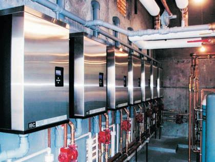
IBC BOILER
IBC BOILER
IBC
HIGH TEMPERATURE BOILER
RETURN FROM HEATING SYSTEM
SUPPLY TO HEATING SYSTEM
LOW TEMPERATURE BASE LOAD
IBC condensing boilers “step back” to deliver high efficiency when needed most.
60% of the heating season, boiler plants only need to run at 40% capacity (less than 15% capacity for 30% of the season). Part-load operation is the rule, rather than the exception.
Water temperature to your building only reach their peak 10% of the season, the rest of the year you can operate well into the condensing range of our boilers. Outstanding reductions in fuel-burn result in a smaller carbon footprint (the lower gas bill doesn’t hurt either).
BALANCE-OF-PLANT & BACKUP
IBC condensing boilers “step up” to give you some extra, high efficiency horsepower on those difficult days.
Low temperature heat pump systems like to run at low temperatures. IBC boilders can step it up a notch for the cold days, and help your system run at peak efficiency. For start-ups, recovery fromnight setback - anytime you need some extra horsepower - IBC is ready to go.
Reduce your peak load electrical consumtion, reduce the size of your heat pump system and Geothermal field, while reducing your greenhouse gas emissions.
HEAT PUMP HEAT PUMP
IBC BOILER

IBC
IBC BOILER
IBC
RETURN FROM HEATING SYSTEM
SUPPLY TO HEATING SYSTEM Visit Booth #63 to see some exciting new product developments from IBC


