18 minute read
A barrier to protect Venice from flooding A system of mobile dams isolates the lagoon from the open sea during high tide and protects the Italian city
A BARRIER TO PROTECT
VENICE FROM FLOODING
Mose is a system of mobile dams that comes into service to isolate the lagoon from the open sea during high tide and protect the Italian city.
Specially designed construction chemical products were used in building the system.
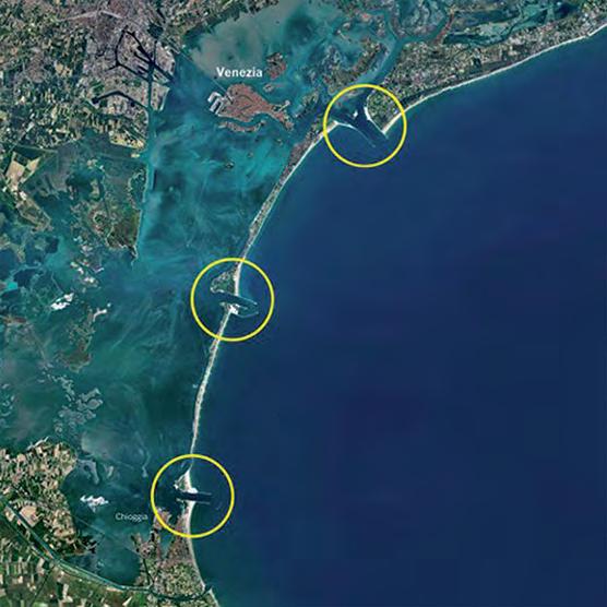
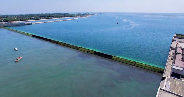
Aerial view of the lagoons and the open sea. The floodgates in the Mose system were raised on 3 October 2020. By 10:15 am, all the gates were in position and expectations were high as the system began its first real test under critical conditions. The 78 floodgates were raised and the difference in level between the sea and the lagoon rose to 40 cm. The level of the lagoon did not rise any further and Venice was not flooded. That was the first official test for a structure that has been designed to protect Venice from high tide - an event that has become all too common.
A long-awaited project
Mose (Modulo Sperimentale Elettromeccanico) or Experimental Electromechanical Module is a hydraulic structure designed to hold back water if it rises above a certain level. The structure is like an automated dam with 20 m wide barriers of various thicknesses, that use their own weight and the force of gravity to help them operate. The idea of using this kind of system was first suggested 40 years ago. Following numerous delays and public enquiries, construction work commenced 20 years ago and is scheduled to be completed by the end of 2021. The system consists of the 78 mobile steel floodgates measuring up to 29 m in height, with each one operating independently. The system is able to isolate the lagoon from the sea during high tide. Other works have also been carried out in the area, such as reinforcing stretches of coastline outside the entrances to the port to alleviate the effect of normal tides, and raising quaysides and paving in the lowest areas of the inhabited areas around the lagoon. The floodgates are housed in concrete caissons positioned on the seabed at the entrances to the three ports on the lagoon - Lido, Malamocco and Chioggia - and are designed to be raised when the sea level rises due to high tides.
The Mose system is designed to protect Venice and the lagoon from high tides of up to 3 m and from a 60 cm rise in sea-levels over the next 100 years.
Outlets to the open sea
The Mose system is made up of four barriers positioned at the three outlets to the open sea. The widest outlet - which is the one closest to Venice - is positioned at Lido and is made up of two channels, each with a different depth. There are two barriers to protect this outlet - the north barrier which is made up of 21 floodgate modules and the south barrier with 20 modules. The two barriers are connected by an artificial island where the equipment used to operate and manoeuvre the system is located. The entrance to the port of Malamocco is the deepest in the lagoon. This is the one used by ships heading to the industrial and commercial port, which is why a navigable basin has been constructed for the ships. The barrier at this entrance is made up of 19 floodgates. The entrance to the port of Chioggia is used mainly by fishing boats and pleasure craft, and a sheltered port with a double navigable basin has been constructed so that boats can enter and exit the port, even when the barrier is closed. This opening is protected by 18 floodgates.
How the Mose system works
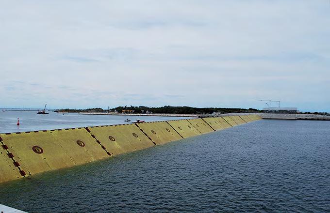
When the floodgates are in stand-by mode, they are completely invisible, full of water and sitting in caissons on the seabed. When there is high tide that could potentially flood the surrounding area, compressed air is pumped into the gates to displace the water. As the water is expelled from the floodgates, they swivel on their hinges, rise up out of the caissons and block the entrances to the lagoon. On average, the time required for the floodgates to seal off the port entrances - including the time required to manoeuvre the floodgates into position - is 4 to 5 hours. The gates only remain in this position during high tide. When the tide ebbs and the lagoon and the sea reach the same level, the floodgates fill with water and then retract into their housing. Each floodgate is made up of a hollow metal structure which is attached to the caisson housing with two hinges. Each floodgate is 20 m wide, while their height depends on the depth of the port entrance channel where they are positioned and their thickness also varies. The caissons housing the floodgates and the mechanisms used to manoeuvre the floodgates form the base of the barrier and are connected to each other by an inspection tunnel. The structure that connects the barriers to dry land is made up of large support housings which contain all the equipment and plants required to make the gates operate correctly.
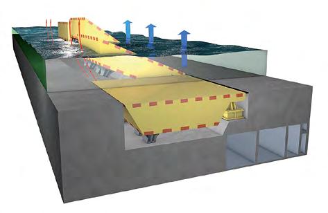
The floodgates are housed in caissons sitting on the seabed. When there is high tide, they rise up and block the sea at the entrance to the lagoon.
Mapei provides solutions for the Mose project
Italian-headquartered Mapei SpA, a world leader in the production of adhesives, sealants and chemical products for the building and construction industry, took part in the Mose project as a technical partner, with a dedicated team that regularly interfaced with design engineers, works directors and contractors. The company’s Technical Services, working in tandem with its Research & Development laboratories, proposed several high-performance products.
Grouting the joints
MAPEFILL MF 610 was specifically developed for this project and was used for grouting the joints and creating the watertight seal required, in order to connect them with matching fittings on the caissons housing the floodgates. The caisson housings were positioned, in sequence, in a trench and were connected together with a special jointing system made up of two separate elements to form a watertight seal. The first element of the system is the so-called ‘Gina ring-joint’ that keeps the external part watertight and forms a temporary watertight seal between one caisson and the next one, while they are being installed. The second element is the ‘Omega seal’ which is installed inside the Gina joint during construction of the caissons and guarantees that the entire caisson remains watertight. Rheoplastic concrete was required for this job to ensure it would maintain a high level of workability for around three hours, at high temperatures of around +35° C. The Gina collar used to house the joint was made from super-duplex stainless steel, an expensive material that left no margin for error during installation. The Gina joint was connected to the concrete caisson by pumping MAPEFILL MF 610 into formwork. This is a fibre-reinforced powdered grout made from high-strength cement, selected aggregates, special admixtures and polyacrylonitrile synthetic fibres. When mixed with water, it forms a fluid grout which does not segregate and is able to flow even into spaces with a complicated shape. The product has low capillary absorption (complying with EN 13057), is highly impermeable to water, adheres strongly to iron and concrete, and is highly resistant to mechanical stress, including dynamic stress. Thanks to its performance characteristics, MAPEFILL MF 610 fulfilled all the client’s requirements during both the qualification tests and the application phase.
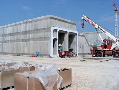
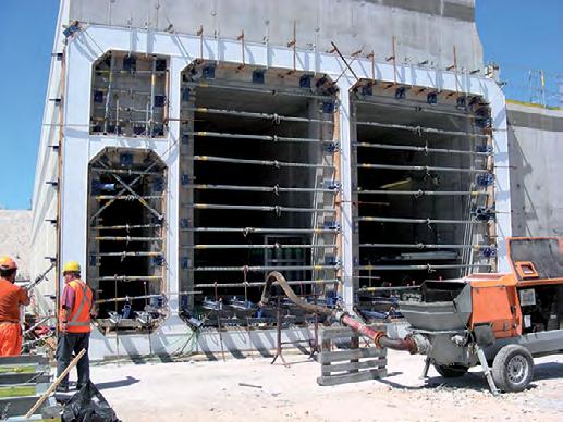
Reinforced concrete caissons being manufactured for use in the Mose project. The joint housings for the caissons were connected together with a jointing system made with MAPEFILL MF 610.
Preparing and positioning formwork on the caissons before pumping MAPEFILL MF 610.
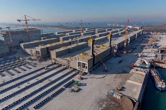
The metal floodgates are anchored to the reinforced concrete caissons with a hinge mechanism which allows the floodgates to be raised and lowered. According to Enrico Pellegrini, former Site Manager for Grandi Lavori Fincosit SpA, a great deal of design work and testing was done to identify the most appropriate products and technologies to fasten a metal component to concrete, so that the hinges could be successfully anchored to the caissons. For this application, Mapei specifically developed MAPEFILL MF, an expansive, fluid mortar for anchoring elements in position with precision. The mortar was applied by injecting it into one side of the hinge and it then flowed to saturate all the gaps and free spaces, to form a single, solid body with the caisson it was anchored to. The waterproofing system for the caissons, which were then placed on the seabed, also had to be carefully designed and thoroughly tested, in order to identify and specify products that would be long-lasting. After performing tests on site and in the lab, the external surface of the caissons was treated with MAPELASTIC FOUNDATION, a two-component, flexible cementitious mortar for waterproofing concrete surfaces subjected to both negative and positive hydraulic pressure. The product chosen for the inside of the caissons, on the other hand, was MAPELASTIC, a two-component, flexible cementitious mortar. It was applied after treating the substrates with a specially designed version of PRIMER 3296. This part of the work, as well as the challenge of anchoring the hinges, was closely followed by the Mapei Research & Development Laboratory in Milan, Italy, which carried out testing on the application of the products for the entire project.
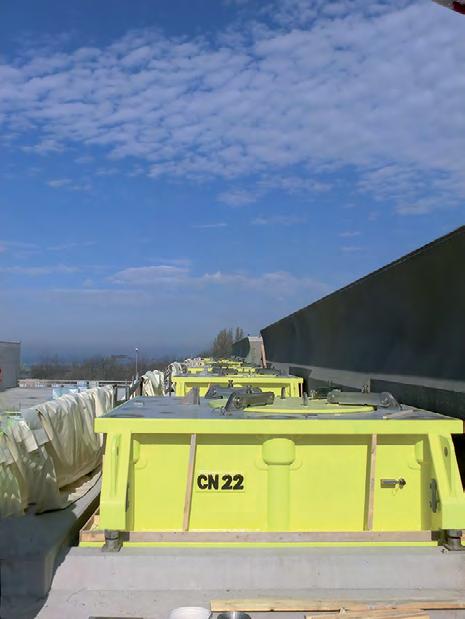
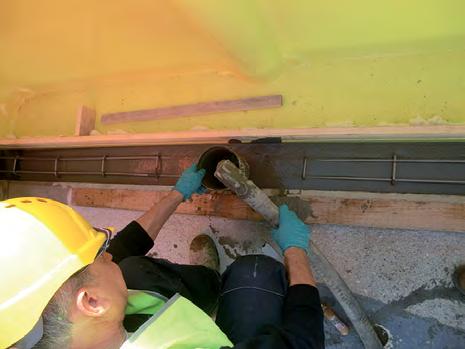
The metal floodgates are anchored to the reinforced concrete caissons with a hinge mechanism which allows them to be raised and lowered. The hinges were anchored using MAPEFILL MF, an expansive, fluid mortar especially designed for this site.
PROJECT TIMELINE
1984
A team of experts is commissioned to carry out a feasibility study for a system to protect Venice from high tides.
1992
The Mose project is presented. The objective is to build it in three years. Construction of the mobile dams gets underway only in 2003 with a target completion date of 2016.
2013
The first gate is raised in October 2013, but enquiries and legal issues lead to stoppage of work on all the open sites, until work finally recommences in 2018.
2020
On 3 October 2020, all 78 gates are raised for the first time at high tide, to prevent the sea water from entering the lagoon.
2021
Completion of the Mose project is scheduled for end-2021.
This editorial feature is based on an article from Realtà MAPEI INTERNATIONAL Issue 83
PROJECT DATA
Project
Mose (Modulo Sperimentale Elettromeccanico) or Experimental Electromechanical Module, Venice, Italy
Owner
Italian Ministry of Infrastructures and Transport - Interregional Department of Public Works for Veneto, Trentino Alto Adige and Friuli Venezia Giulia Former Magistracy for the Waters of the Province of Venice
Design
Italian Ministry of Public Works Technital
Period of construction
Ongoing from 2003
Malamocco site director
Enrico Pellegrini
Malamocco site main contractor
Grandi Lavori Fincosit SpA
Project costs
Construction cost - EUR 5.5 billion Cost of repairing damaged and deteriorated structures - EUR 700 million Cost of routine maintenance (estimated) - EUR 100 million/year
INTERVENTION BY MAPEI Period of the intervention
2007-2015
Contribution by Mapei
Supply of products for grouting the Gina joints, anchoring the hinges and waterproofing the caissons
Mapei products used
Sealing Gina joints - MAPEFILL MF 610 Anchoring the hinges - MAPEFILL MF Waterproofing caissons - PRIMER 3296, MAPELASTIC, MAPELASTIC FOUNDATION
Website for further information
www.mapei.com
Source of information in the article
Italian Ministry of Infrastructures and Transport - Interregional Department of Public Works for Veneto, Trentino Alto Adige and Friuli Venezia Giulia Former Magistracy for the Waters of the Province of Venice
SOLVING THE PROBLEM OF THE HINGES
Mr Enrico Pelligrini, former Site Manager for Grandi Lavori Fincosit SpA, the Main Contractor for the Malamocco site, elaborates on a major challenge in the project and how it was successfully addressed. Question: Mr Pellegrini, what role did you have in the Mose project?
Mr Enrico Pellegrini
Answer: From 2005 to 2015, I was the manager of the site where the precast concrete caissons were manufactured for the inlets to the ports of Lido San Nicolò and Malamocco. The site was located on a 13-hectare artificial embankment, created specifically for the project on the island of Pellestrina.
Q: Which part of the work on the Mose project proved to be the most challenging, with regard to its design and the materials to be applied?
A: The structure of the Mose barriers is made up of two main elements - the reinforced concrete caissons which anchor the barrier to the seabed and the metal floodgates which are those big, yellow boxes which we can see rising up out of the sea to stop high tides. The two elements are joined together by a highly sophisticated device - the hinge. The caissons are fixed permanently to the seabed, whereas the metal floodgates can be removed periodically to carry out scheduled maintenance work.
This means that the hinge element must allow the floodgates to be disconnected from the caissons, which is why it is made out of two parts - the female part which is fastened permanently to the caisson and the male part which is an integral part of the floodgate. To anchor the steel female part to such an enormous reinforced concrete structure (the largest caissons are as big as a three-storey apartment block) with pinpoint precision was a really challenging design and construction matter, which we managed to overcome, by applying materials of the very highest quality and by planning the application procedures down to the minutest details.
Q: What problems did you have to overcome to anchor the hinges in place?
A: It was extremely important that the female hinges integrated with the foundation structure to perfection. The difference between the two materials (reinforced concrete and steel), in terms of thermal and elastic behaviour, the difference in the design codes and construction methods applied, as well as the need to create a seal that would remain perfectly watertight at a great depth, required a very careful, in-depth study of the behaviour of the two elements when joined in one single element. Which is why MAPEFILL MF was chosen - a product that would be able to guarantee the maximum level of adhesion between the two elements, with high mechanical properties, while maintaining sufficient elasticity and the ability to be distributed into any tiny gaps in the spaces left, to connect the two elements together.
Q: Any structure immersed in water must be fully waterproof. What were the most significant characteristics of this part of the work?
A: As I mentioned previously, while the floodgates will have to be extracted so their protective waterproofing system can be replaced and maintained at regular intervals, this won’t be possible for the concrete caissons.
This made it extremely important to design one or several systems that would completely waterproof the structure. This is why, for the construction joints, three waterstop systems were provided, with the external one coated with a cementitious waterproofing membrane. In spite of all these precautions, after carrying out a thorough analysis of the costs and benefits, the contractor decided on site to integrate these safety systems even further, by treating the entire surface of the caissons, from top to bottom, with a specially designed formula of MAPELASTIC FOUNDATION mortar, which was further integrated by applying a coat of a primer specifically designed by the Mapei R&D laboratories.
Q: Because of the new materials and technologies adopted, do you think the Mose site can be considered a pilot project for other sites of this type?
A: Obviously I can only speak for the work carried out on the site I was involved with, but I would say that, more than anything else, it was the way the project was managed from a technical point of view that could be used as an example of how to set up a major works site.
One such example is the care taken in choosing the right materials, which was dictated not only by the principles of affordability, but also by means of a long series of tests and cost/benefit evaluations.
Q: You worked very closely with Mapei Technical Services and the company's R&D laboratories in Milan. How did this team-approach work exactly?
A: I was in no doubt about MAPELASTIC’s waterproofing capacity and elasticity, but I was still concerned about two factors - how strongly it would bond to the substrate and its durability. That’s why I personally wrote out a procedure which included an extensive range of tests to be performed on-site to demonstrate which would be the best technology to prepare the base, but also which was the best primer to apply in order to guarantee the highest level of adhesion for the membrane. The Mapei product performed better than those of the competitors, thanks also to the direct and prompt interest shown by the company's R&D lab which made some slight modifications which greatly improved its final performance properties. Besides, it was really comforting to be able to rely on an experiment carried out by the laboratory at the Polytechnic of Milan, which demonstrated that MAPELASTIC maintains its performance properties, even after a series of extended immersion cycles in seawater.
Also worth highlighting is how the Mapei lab followed our progress throughout the entire construction which lasted around one year, by coming to monitor and test the application of the product on a regular basis.
We found this to be very reassuring and it provided us with a further guarantee of the final quality of the work we carried out on site.
NEW CAT 657 WHEEL TRACTOR-SCRAPER
IMPROVES PRODUCTIVITY AND OPERATING EFFICIENCY
Featuring the field-proven, twin-power design to boost cycle times, the new Cat 657 Wheel Tractor-Scraper (WTS) improves productivity and operating efficiency, to deliver low-cost earthmoving. A 7% increase in fuel efficiency over the 657G WTS means more material moved per unit of fuel burned, and improved onboard payload estimating accuracy helps optimise productivity. The largest open bowl scraper in the Caterpillar line, with a rated load of 52 tons, now has a more spacious cab to boost operator comfort and efficiency in high volume earthmoving, highway construction and mining applications. The 657 features on-the-go weighing through Payload Estimator, allowing the new WTS to achieve 95% load accuracy, so operators more easily reach target load goals. When working in colder climates, the unique AutoStall feature quickly brings the transmission to operating temperature at start-up, so the 657 gets to work faster. Ground Speed Control lowers fuel consumption by allowing the operator to set the desired top speed, allowing the machine to find the gear that works best for the engine and transmission. The two-engine design includes the Cat C18 powering the tractor and Cat C15 in the scraper, both meeting stringent US EPA Tier 4 Final/EU Stage V emissions standards. Its Advanced Productivity Electronic Control System (APECS) allows the Cat 657 to better utilise engine power and torque, resulting in more material moved throughout the shift. The transmission features Electronic Clutch Pressure Control which improves shift quality and fuel efficiency. New hydraulic disc brakes improve braking performance and reduce maintenance. A cab interior 21% larger than the preceding model, the 657G, improves operator comfort and provides good visibility to the bail, cutting edge and bowl of the new 657. The air suspension comfort seat adjusts and rotates 30°, to reduce fatigue, while the new Advance Ride Management adjusts damping to match ground conditions, resulting in a smoother ride for the operator. Automatic HVAC temperature control and defroster come standard for increased operator comfort. The new power access ladder enhances operator safety when entering and exiting the cab. The new high-pressure steering system requires less steering input, which bolsters operator efficiency and productivity. Automatically engaging when the machine is in eighth gear, engine overspeed protection assists in slowing machine speed when approaching engine limits. Sequence Assist, a new option on the 657, automates many operator inputs, each cycle, to simplify machine operation. The 657 tractor includes a new hydraulic on-demand fan that increases engine fuel efficiency. The machine also has draft-arm overflow guards which prevent material accumulation between the draft arms and bowl sides. Ground-level access for fuel fill and all daily maintenance points increase service efficiency and safety to increase machine uptime. Integrated Payload Estimator and Cat Product Link technologies provide real-time payload, machine location, fuel usage and idle time information as well as diagnostic fault codes - all to significantly increase fleet management efficiency. A collective view of critical machine operating data is accessed via VisionLink, from anywhere there is an internet connection.
Who’s Who In Engineering, –––––– Outside Back Cover Singapore (3rd Edition)
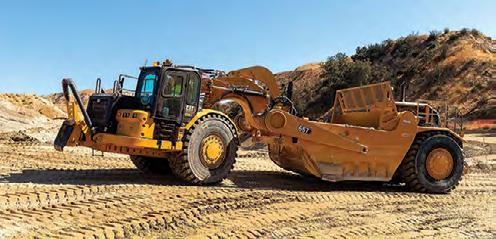
The new Cat 657 Wheel Tractor-Scraper features a twin-engine design.
ADVERTISERS’ INDEX
IES Chartered Engineer ––––––––––––– Inside Front Cover IES Membership –––––––––––––––––– Inside Back Cover


