15 minute read
Design economics of trimaran wind turbine installation cum decommissioning vessels


DESIGN ECONOMICS OF TRIMARAN
by Bob L Y Cheung, Bob Cheung Offshore Consultants
INTRODUCTION
In the article ‘Design Economics of Multi-Purpose Offshore Wind Farms’, included in the March 2021 Issue of ‘The Singapore Engineer’, published by IES [1], a cost-saving idea for the development of a multi-purpose offshore wind farm was proposed, to reduce the lifetime cost of the project. The most significant suggestion in it is to bridge-link all the wind turbines, which will result in major savings in the array cable costs including the cost of materials, installation, operation and maintenance. The bridges can also function both as array cable trays and as an offshore solar farm. Effectively, the offshore wind farm is transformed into a semi-onshore wind farm, where accessibility is greatly improved by a network of inter-connecting bridges and everyone can have easy access to each of the 100 wind turbines. The need for array cable installation vessels, crew transfer vessels and service operation vessels will almost vanish. However, there are other cost-cutting areas worthy of in-depth investigations. This article explores a different approach in relation to installation, maintenance and decommissioning of offshore wind turbines. A similar idea was published in IES Journal in 2010 [2]. To appreciate the magnitude of the cost-saving that is possible with this concept, it is more meaningful to consider a hypothetical wind farm design project, based on a simple design, that will enable developers to quantify the possible reduction in the investments. A note of caution is necessary, in that this is a simplified design, based on simple calculations and years of offshore engineering experience to support the ‘great savings possible’ argument. The design is based on API-RP-2A and the AISC Steel Construction Manual, but does not follow the IEC 61400-6, 2020 code.
DESIGN OBJECTIVES
To minimise the project cost, we should consider reducing the weight of the standard, tubular column, wind turbine tower, and making it more maintenance-, installation-, and decommissioning-friendly. This means that we should avoid the deployment of jack-up, wind turbine installation vessels, semi-submersible heavy lift barges and big helicopters. This article seeks to promote the following actions, to achieve huge savings: • Fabricate and fully assemble all the wind turbines in the yard. • Loadout all the fully-built wind turbines, in a vertical position, onto the trimaran construction vessel. In our design example, the trimaran vessel can accommodate three whole wind turbines, in one mobilisation. • Tow to site and install the turbines using the float-over method. All the foundation jackets have been pre-installed. • The trimaran vessel returns to base for a loadout of additional wind turbines and their mobilisation. Alternatively, more trimarans can be built to speed up the project schedule. • Use the same type of trimaran vessel to decommission all the wind turbines when the wind farm design-life has matured.
DESIGN BASIS
1 Water depth
115 ft (35 m) 2 Distance from shore 19 miles (30 km) 3 Turbine cut-out speed 56 mph (25 m/s) 4 100-year wind speed 100 mph (45 m/s) 5 Tower height 350 ft (107 m) 6 Tower dimension at top 30 ft x 30 ft (9 m x 9 m) 7 Blade diameter 538 ft (164 m) 8 Nacelle size 80 ft x 30 ft x 20 ft (24 m x 9 m x 6 m) 9 Nacelle & blades weight 500 tons 10 Solar panel weight 50.7 lb each (23 kg each) 11 Subsea array cable weight 39 lb/ft (58 kg/m) 12 Surface array cable weight 20 lb/ft (30 kg/m) 13 All steel to ASTM G50 50 ksi
DESIGN ASSUMPTIONS
• There are 100 turbines in the wind farm and they are all bridge-connected to provide support for the solar panels and the array cables [1]. • A deck is needed for each wind turbine to support the turbine tower during loadout and float-over operations. It will also be used for decommissioning. • The wind farm is about 19 miles (30 km) from shore and in shallow water.
DESIGN CONSIDERATIONS
Wind turbine tower
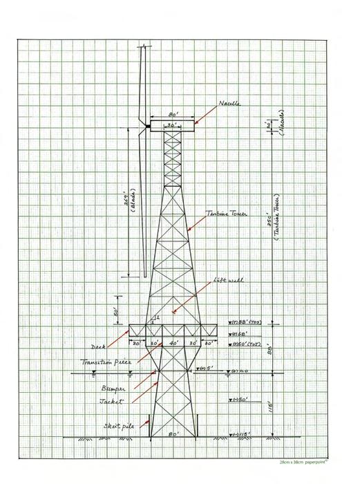
The standard supporting structure for the nacelle/ blades system is a large diameter, tubular column that houses all the power and communication cables and electrical equipment. Structurally, a tubular member is not an efficient bending element. To achieve the needed structural bending stiffness, the diameter can be more than 30 ft in a modern wind farm. However, a tubular column is easy to fabricate if a big rolling machine and advanced welding equipment are available. This is ideal for high labour-cost countries, but highly questionable for the rest of the world. For installation, a contractor will most likely use a jack-up, wind turbine installation vessel to lift the tubular turbine tower in several shorter sections. The whole process is to carry out the lifting, piece-by-piece, about 300 ft to 500 ft above water. However, it is a risky operation. Why should we use this method for wind turbine installation? We would like answers to the following questions: • Can we have a simple and less-risky installation method? • How can we replace a piece of heavy equipment inside the nacelle during major repair work? • How do we decommission the wind farm? Of course, we always have to think of ways to cut costs. Our comments would be the following. • The proposed trimaran installation cum decommissioning vessel is a better, cheaper and safer alternative. • If we were to use a jack-up installation vessel or a semi-submersible barge to reach the top opening of the nacelle, the cost could be prohibitive [1]. Hence another solution must be found. • If we were to use a jack-up vessel to remove all the 100 wind turbines, the cost could be few hundred millions of dollars, at today’s day-rates [1]. At the end of the design-life of the wind farm, the cost could increase to billions of dollars. A similar situation is already happening in the North Sea, for decommissioning all the non-producing offshore platforms. It is a multi-billion-dollar project, spanning over many years. We have to look for a different approach. We believe a turbine removal mechanism should be incorporated into the design. A workable solution is a truss type tubular tower design (Figure 1). The base dimension of this structure is 100 ft x 80 ft, which is much stiffer than a 30 ft diameter tubular column. The first mode frequency is much higher and wind excitation is a non-issue. The space inside the truss tower is big enough to accommodate a lift-well to lift heavy equipment. The lifting tools can be installed on an as-required basis, as cable jacks are readily available in the market. Since the blades are light and flexible, they may hit the truss tower during a storm. This is a simple design issue that can be taken care of by the turbine manufacturers. Based on simple calculations, without optimisation, the weight of this structure is about 330 tons and most of the tubulars are less than 0.5 inches thick, which means that welding is simple and high quality welds can be achieved using 6GR welders. There are many qualified welders in Batam, Indonesia; Johor, Malaysia; Thailand; and Singapore. We can fabricate the truss tower on the ground and roll it up in sections to form a standing tower. Assembling the nacelle and the blades on land is much easier than doing it offshore. If the fabrication rate is 80 man-hours per ton, due to more out-fitting work inside the tower, the total fabrication time needed will be 330 x 80 x 100 = 2,640,000 hours.
Supporting deck structure
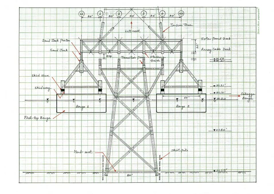
A deck of 160 ft x 100 ft (Figure 1 and Figure 2) is needed to support the turbine truss tower. It can provide many additional functions: • To receive cables coming down the nacelle and from other turbines via inter-connecting bridges, and to re-direct them to the out-going bridge. • To operate as part of the solar farm. • To provide a laying-down area for maintenance and repair work. • To act as a carrier frame for the loadout of the wind turbine using skid frames (Figure 2 and Figure 3). A loadout skid frame is shown in Figure 4. • The trimaran vessel can carry three fully assembled turbines and the corresponding decks in one mobilisation (Figure 2 and Figure 3).
• To act as a bridge above the jacket for the float-over operation (Figure 5 and Figure 6). • Using the deck and the trimaran vessel to decommission all the turbines in a reversed operation. In this case, we will use heavy jack-up equipment in place of sand jacks (Figure 5 and Figure 6). The deck weight is about 270 tons, assuming that a very limited number of deck plates and fewer secondary beams will be used. Cable trays can also be hung from the underside of the solar deck, to save deck steel, if possible. If the fabrication rate is 130 man-hours per ton, the total fabrication time needed is 270 x 130 x 100 = 3,510,000 hours.
Turbine jacket foundations
As stated under ‘Design Assumptions’, all turbine foundations are jacket structures, but they will have the following design restrictions: • The top of the jacket measures 40 ft x 60 ft (Figure 2) and the elevation is set at +50 ft. Hence, the truss turbine tower will be 370 ft above the solar deck (Figure 1). • The four-leg jacket will have two outrigger legs on either side, to receive the eight-leg deck structure (Figure 6). • The jacket legs will have a small batter angle to suit the trimaran vessel opening and the loadout skid frames, to achieve a 10 ft all-round clearance (Figure 6). • All jackets will have skirt piles (Figure 1). • Transition pieces will be field-adjusted to correct the as-installed, out-of-vertical and out-of-level conditions.
However, the jacket should have been levelled, after piling is done, using jacket levelling tools. • Small barge bumpers will be installed for the float-over operation and serve as a boat-landing, afterwards (Figure 1). • The jacket will have only mud-mats, pad-eyes, anodes and grout-lines (Figure 6), making it as light as possible. We assume the jacket and piles will be 500 tons each and the fabrication rates will be 50 man-hours and 10 manhours per ton, respectively. The total fabrication time is 500 x 50 x 100 + 500 x 10 x 100 =3,000,000 hours.
Turbine skid frames
We will use two skid frames for each turbine (Figure 4, Figure 5 and Figure 6). Each skid frame will have four skid shoes. If the total loadout weight is 2000 tons (contingency factor added), each skid shoe should be designed for 250 tons plus the induced loads when going across the bulkhead. A lot of design and construction details can be found in [3]. If we do not want to fabricate timber-supported skid shoes, we can consider using air-cushion pads [4] and [5], but they tend to burst easily due to not-too-perfect road surface preparation. One can also use multi-wheel transporters, which can be expensive.
Trimaran wind turbine installation and decommissioning vessel
In this design, we regard the trimaran vessel as the most critical piece of wind farm construction equipment and every operation must be tailor-made to suit the vessel. With it, we should be able to shed off hundreds of millions of dollars in the project. A large capacity jack-up installation vessel may cost USD 500 million to build, which explains why its day-rate must be expensive [1]. In order to install three or four turbines in one mobilisation, the new jack-up vessel must have a large open deck space to store all the nacelles, blades and turbine towers which will be cut up into many shorter sections. The jackup vessel will also need lots of space for a crane, a large boom-rest and a living quarters building to house all the construction workers. These requirements will mean a bigger hull, stronger legs, a bigger crane and more powerful jacks to jack up the new super-large and heavy jack-up vessel. A bigger jack-up vessel means higher investments. This piece of modern jack-up equipment will push up the project cost and will have a big impact on timely investment returns. We believe a trimaran vessel is an attractive alternative. The cost could be under USD 50 million or even less if we can build it with secondhand barges. The trimaran vessel is made up of three barges (Figure 3). Basically, it is a big catamaran with an added outrigger barge. The catamaran consists of two 500 ft x 80ft x 30 ft flat-top barges and the outrigger barge measures 360 ft x 80 ft x 30 ft, which will provide additional transverse stability. A big barge is necessary to provide the required reserve buoyancy. Sourcing 500 ft barges may not be easy as most of the flat-top barges in the market are less than 400 ft. However, due to the poor offshore installation business, there are 10-year-old to 20-year-old launch- and float-over-barges in the market, with each costing less than USD 10 million. They come with many useful built-in features. If we decide to build one, the cost will not be expensive as the fabrication specification is relatively simple. The barge should have ballast tanks but without the internal fast-ballast system. We can use deck-mounted pumps for the loadout operation, but not for the floatover operation. Loading out a ‘statically determinate’ structure is a simple operation. If the long-term rental rate of a small heavy transport vessel is affordable, we can incorporate it into the trimaran system to speed up the project. The outrigger barge can also provide additional deck space for the construction equipment (Figure 2 and Figure 3).
LOADOUT AND INSTALLATION AS WELL AS DECOMMISSIONING
To perform a platform float-over operation, the standard practice is to prepare a very detailed procedure and submit it to the selected certification authority for approval. One has to make sure that every offshore operation is well-covered by insurance. The procedure will need many weeks to prepare and is subject to many
Figure 2: Wind turbines on the trimaran vessel (side view).


risk assessment reviews and meetings. This is outside our scope, but we will outline all the major points to show that the trimaran float-over is a workable solution. The float-over operation for a wind turbine is less problematic than that for an offshore platform deck which has a lot more sensitive equipment and miles of internal piping runs. Any repairs offshore, even for few small piping runs, will delay the start-up operation. In general, wind turbine float-over has fewer problems. Listed below are the important items that require careful consideration: • The yard must have a long loadout bulkhead, of not less than 500 ft, to berth the trimaran vessel. The water depth at the quayside should be 20 ft or more. • The loadout weight of a fully assembled wind turbine, together with the deck and the skid frames, is assumed to be less than 2000 tons, in our example. We can use this value and the induced loads to check the strength of the structures, the soil foundation, the skid-ways, the bulkhead and the barge deck strength. • Loadout can be done using skid shoes or transporters, or by other means. • After loadout, all three turbines should be tied-down in two directions, to achieve greater stability. • Towing to site for installation, assuming all the jackets have been pre-installed by conventional, small size derrick barges. • To lower the wind turbine and the deck onto the ‘eightleg’ jacket using the four sand jacks built into the skid frames. • After float-over, welders will weld up all the connections and the trimaran vessel will move to the next location for the wind turbine installation. There will be no skidding operation offshore for safety reason. • We will need a small crane barge to assist all the remaining hook-up activities. • For decommissioning, we will use heavy jack-up equipment to jack-up the deck and the turbine. The equipment is readily available in the market.
CONCLUSION
The proposed concept is labour-intensive, which is clearly not suitable for Europe. However, for developing countries, it may not be a bad idea, due to the higher job opportunities that the proposed concept can bring. The total man-hours needed for the construction of the turbine towers (2,640,000), the supporting deck structures (3,510,000) and the turbine foundations (3,000,000) is 9,150,000, which can keep a few yards busy for many months. To justify the extra labour cost, we have to rely on the savings generated by the trimaran vessel concept, both in installation and decommissioning. After the project is done, we can sell off the trimaran vessel as three, separate, flat-top barges,

to recoup some of the investment. Net-zero is a global objective and all countries should participate in efforts to achieve it. We believe this new concept may make it easier for developing nations to take part. Of course, this is a good business opportunity if the trimaran concept is acceptable to the developers.
REFERENCES
[1] Cheung Bob L Y (2021): ‘Design Economics of Multi-Purpose Offshore Wind Farms’, The Singapore Engineer, March 2021, 22-28, IES. [2] Cheung Bob L Y (2010): ‘Catamaran Gantry Crane for Engineering-Procurement-Construction-Installation Contract’, IES Journal Part A: Civil & Structural Engineering, Vol 3, No 4, 257-266, IES. [3] Cheung L Y and Foong K G (2008): ‘Design Considerations of a Loadout Skid Frame for a 14,000 ton Upper Hull Structure’, IES Journal Part A: Civil & Structural Engineering, Vol 1, No 1, 83-95, IES. [4] Cheung L Y (1989): ‘SIA Hangar Roof at Changi Airport: Bidding, Fabrication and Installation’. Journal of the Institution of Engineers, Singapore, Vol 29, No 1, 67-81, IES. [5] Cheung Bob L Y (2017): ‘A Proposed Multi-purpose 20,000 T Floating Gantry Crane System’, The Singapore Engineer, June 2017, 30-33, IES. (More information may be obtained from bob.cheung@ rocketmail.com)
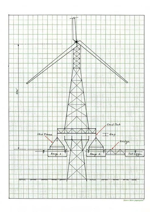
Figure 5: Float-over.