
8 minute read
Kariba Dam rehabilitation a major African concrete project


By Eamonn Ryan with technical information supplied by CHRYSO
The Kariba Dam was completed in 1959, at a time when it was the largest dam in the world, located on the Zambezi River between Zambia and Zimbabwe.
Advertisement
Designed as a double curvature concrete arch dam, the kariba dam has a height of 128m and with a crest length of 617m, for a holding capacity of 181 billion cubic meters of water.
It originally had a projected lifespan of 140 years, but unforeseen structural weaknesses, including a weak rock formation at its base were detected. It is one of the most important hydroelectric power stations in africa, but these years of wear and tear mean the dam has been in need of renovation for some time to ensure its continued functioning. Efforts have been made to modernise and improve the dam over the years and now the most significant uSd294 million renovation project is underway.
In particular, the dam’s walls have suffered from significant erosion, and there had been concerns about the potential for the walls to collapse. the project is a joint effort between Zambia and Zimbabwe, with support from international organisations such as the World bank. the project aims to modernise and improve the dam, making it safer and more reliable for years to come.
was being eroded every time spillway gates were opened, inching closer to the dam structure and would eventually lead to the collapse of the dam wall with serious challenges for the region.
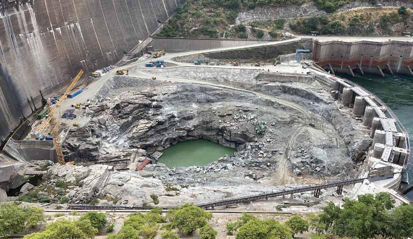
the natural river bed downstream of the dam has eroded over time as a result of the heavy spillage of flood waters, particularly in the dam’s early years, to form a deep plunge pool. The Zambezi River Authority has monitored the performance of the dam infrastructure, including the plunge pool, since its impoundment in 1958.
the unit has implemented routine interventions to slow the expected erosion of the plunge pool’s natural rock floor. this includes controlling the volume of spillage by opening fewer of the sluice gates at a time. the construction of a second power station in the late 1970s also reduced the spillage as more water was diverted for power generation than before. as a result, the natural erosion has slowed and no significant changes to the plunge pool floor have been recorded in the last 15 years.
Excavating the downstream end of the plunge pool will increase its size and reduce the pressure that the water spilling into the plunge pool exerts on its base thereby slowing the erosion of the natural rock floor.
reducing the slope of the downstream end of the plunge pool will decrease the amount of swirling and ensure the smooth flow of water out of the pool and into the river. reinforcing the wall of the plunge pool will strengthen and stabilize it.
the works on site, which follow the procurement and documentation phase of the project, include:
• site installation
• the construction of permanent and plunge pool access roads
• the construction of a coffer dam and dewatering of the plunge pool the rehabilitation works are envisaged to double the lifespan of the dam. the renovation project involves significant work on the dam’s walls to reinforce it with concrete, with the spillway gates being upgraded to improve their efficiency. In addition, the dam’s power station is being upgraded with new turbines and generators, which will increase its capacity and efficiency. the project is also focused on improving the environmental sustainability of the dam. the renovation project includes measures to improve water quality and to protect the local ecosystem. In addition, the project aims to improve the livelihoods of local communities by supporting sustainable economic development. the kariba reservoir supplies water to two underground hydropower stations with a total capacity of 1 830MW generating more than 10 035 gWh of electricity annually. The North Bank Power Station is operated by ZESCO in Zambia and has an installed capacity of 1 080 MW. The South Bank Power Station is operated by ZPC in Zimbabwe and currently has an installed capacity of 750 MW, with projects underway to increase this to 1 050 MW. progress has been made, and the project is currently on track to be completed in 2024, being currently approximately 80% complete. the project involves reshaping the plunge pool at the foot of the six decades-old dam and refurbishment of the spillway. the rock
• the excavation works and fault treatment
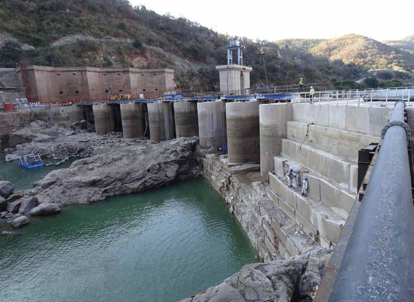
• refilling the plunge pool and the demolition of the coffer dam on completion of the works the six sluice gates in the upper part of the concrete dam wall together form the spillway through which water is released into the plunge pool to manage the reservoir water levels. over time, concrete exposed to water expands. this minimal expansion is natural and is expected. the spillway refurbishment will mitigate potential risk to the operation of the spillway and will enable the Zambezi river authority to continue to manage the water levels in the reservoir effectively and guarantee the safety of the dam for many more years. the reshaping of the plunge pool of an existing dam is a world first. funDing:
Organisation financing
Zambezi River Authority USD19.2 m africa development bank uSd75 m loan & grant
European union uSd100 m grant
Swedish government uSd20 m grant the World bank group uSd75 m loan
CO n TRACTOR s g ET CLOsER TO KEY OBJECT i VE
Contractors are getting closer to the key objective of the kariba dam rehabilitation project – to reshape the plunge pool below the dam wall and arrest any further erosion.
Concrete is a central element of this world class engineering project, and CHRYSO Southern Africa’s Zambian distributor, Mart Solutions has been one of the key suppliers of construction chemicals to main contractor razel-bec since the beginning of the project. this collaborative effort over the past several years has ensured the project’s steady progress. With the aim of stabilising the plunge pool at the foot of the 138m high dam wall, the project is using vast quantities of concrete in a range of applications.
“the ChrySo aquabeton product played a critical role as an anti-washout admixture that increases the cohesion of the concrete mix.” the total volume of concrete used – which includes the coffer dam and underwater works as well as excavation – is almost 26 500m3 at the coal face is Mart Solutions director, Martie Coulson.
“among the first challenges we faced was in the construction of piers for the temporary coffer dam, where concrete had to be poured underwater to create a foundation,” says Coulson. “difficulties in finding bedrock for piers 7, 8 and 9 –as well as for the dam’s right bank – meant that 22,000 m3 of concrete had to be placed underwater.” this arduous process – which took six months and was completed in September last year – involved pumping concrete to 25m deep, with divers handling the 125mm diameter pipe to place the concrete. adding to the complexity was the movement of water from the nearby Zimbabwe’s hydro-electric turbine outlet, which exacerbated the ‘wash’ off the concrete into the surrounding water.
“this raised the risk of the cement being washed out of the mix, leaving the aggregate behind as well as further reducing visibility for the divers,” she explains. “the ChrySo aquabeton product played a critical role as an anti-washout admixture that increases the cohesion of the concrete mix.” this allowed the placement of a concrete base for the three piers, measuring some 15m wide and 20m deep. another important aspect of the project is repairing a fault in the rock at the foot of the kariba dam wall. Stitching of the fault will include the use of 40mm anchors in the rock with ChrySo NS grout added to a concrete mix. In addition, 20mm, 25mm and 32mm anchors will be used and will be secured with a.b.e. dura.grout supplied by Mart Solutions.
“Some 7 071m3 of specialised concrete will be used for the large 90m high, 45m wide and 2.5m thick wall which will be built in front of the fault as a protective shield,” she says. “this will be fixed onto the 12m long, 40mm diameter anchors in the wall, which will in turn be secured 10m into the rock.” a combination of ChrySo omega 162 and ChrySo Fluid optima 206 will be used in conjunction with densified silica fume and fly ash in the concrete mix for the wall – to assist in preventing the temperature rise in the concrete during placement and to avoid cracking. this is important due to the high ambient temperatures of up to 40°C.
“We have been running laboratory trials for three years to ensure that the concrete mix design will meet the standards specified by the engineers for the wall to ensure that the concrete will remain below 55°C during placement,” she explains. as part of the preparation of the concrete, therefore, a chiller plant will be cooling the water and aggregate before it is added to the mix. In another aspect of the project, Mart Solutions is providing the anchors to secure the safety nets which are being installed against the risk of rockfalls in the excavation, as well as a.b.e. dura.grout for securing the anchors. this non-shrink cementitious grout quickly develops placeable consistency and remains cohesive. ChrySo Jet 30 is also being supplied for shotcreting, mixing with concrete as it is sprayed to ensure adhesion to the rock surface.
“as the coffer dam is dewatered, the contractors are able to start micro-blasting to clear rock from the plunge pool,” she says. “the walls must then be secured to prevent any rocks from falling.”
Mart Solutions has already provided the ChrySo omega 162 superplasticer for building the coffer dam piers. ranging from 250 tonnes to 700 tonnes in weight, these piers measure 5.5m tall.
“the new generation ChrySo omega 162 high range water reducing plasticiser played an important role to reduce water demand, thereby increasing the concrete’s durability,” she says. “It also improved the concrete’s cohesion and lowered its viscosity, for better homogeneity and off-shutter finish.”
ChrySo omega 162 allows concrete to exhibit extended workability characteristics, while ChrySo Fuge b – a poreblocking permeability reducer for mass concrete – was used in the coffer dam piers to prevent the penetration of water under pressure.
ChrySo obtained the following additional engineering information for Concrete trends relating to the project:
“the reinforcement of the protection wall will be made by one to three layers of hb32mm rebars placed in a mesh of 250mm spacing. the rebars of 450Mpa yield strength will be supplied straight and cut and bended on site. Each bar may be unique to match perfectly with the rock surface. t ies in hb20 will then hold the layer together.
“the protruding part of 40mm anchors bars already installed on the rock face will then have to be especially bended in place and adjusted to the final concrete surface. the constraint of these anchors would prevent the preassembling of the reinforcement which will be mostly assembled in directly in place.
“around 200t of reinforcement should be placed in this protection wall.
“the concreting of the protection wall in 1.5m layers will follow the reinforcement few steps behind for a continuous activity. Safety of all the operations will be a major concern as they will be done along an 80m height rock face.
“the reshaping of the plunge pool required the removal of around 300 000 m3 of rock at the dam’s foot. the operations done using blasting and micro blasting are closely monitored by a network of six to nine seismographs place all around the hole and vibrations limited to the surrounding structure (e.g., 9mm/s on the dam). the materials are then loaded and evacuated to the dump site at 2.5km from there. to allow these operations, the water is pumped in advance at 1m/day. this dewatering and its effect on the dam are also closely monitored by several instruments such as piezometer and inclinometer. the design of the pumping system was a challenge as the water pumper must be released 90m higher and base on a theoretical seepage of 100ℓ/s through the rock mass. the presence of the plunge pool pit in the middle of the work site is also a challenge in term of safety and work organisation. the pumps in the bottom must be regularly removed when blasting around the pit are made. the final surface excavated are then subject to a geological mapping and protection works involving shotcrete and anchors 25/32mm decided. the slopes are then covered by a safety net preventing rock fall on the people and machine working lower in the pit.
“there were no specific problems relating to the cement as such, more on getting the correct aggregates. Cement is from Lafarge Zambia now known as Chilanga Cement.” n


