Living Prototype: IAAC_ITKE_CITA_
“LIVING PROTOTYPES: Digital Fabrication with Biomaterials”
The Institute for Advanced Architecture of Catalonia in Barcelona (Earth), alongside its industry partner WASP, collaborated with CITA from the Royal Danish Academy in Copenhagen (Bioplastics) and ITKE from the University of Stuttgart (Flax Fibre) respectively.
“The digitally fabricated prototypes for building components, made with the bio-based materials earth, flax fibre and bioplastics, were developed in a European research project.
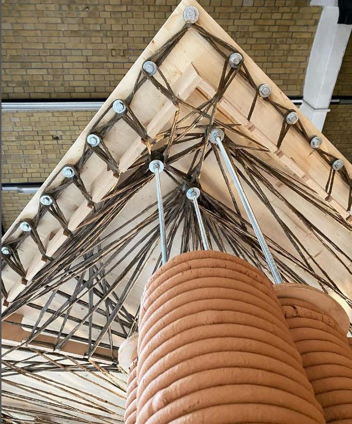
Living Prototypes’ pavilion is the product of prefabricated components in three different building materials, showcasing the future of a circular and sustainable construction. IAAC’s earthen columns were printed in Barcelona and transported to Berlin, where they were attached to ITKE Stuttgart’s flax fibre and timber slabs. CITA’s cellulose wall elements close the loop on a floor-to-ceiling 1:1 scale demonstrator on the promising future of construction with biomaterials and digital fabrication methods.
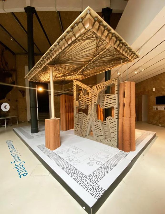
Living Prototype production
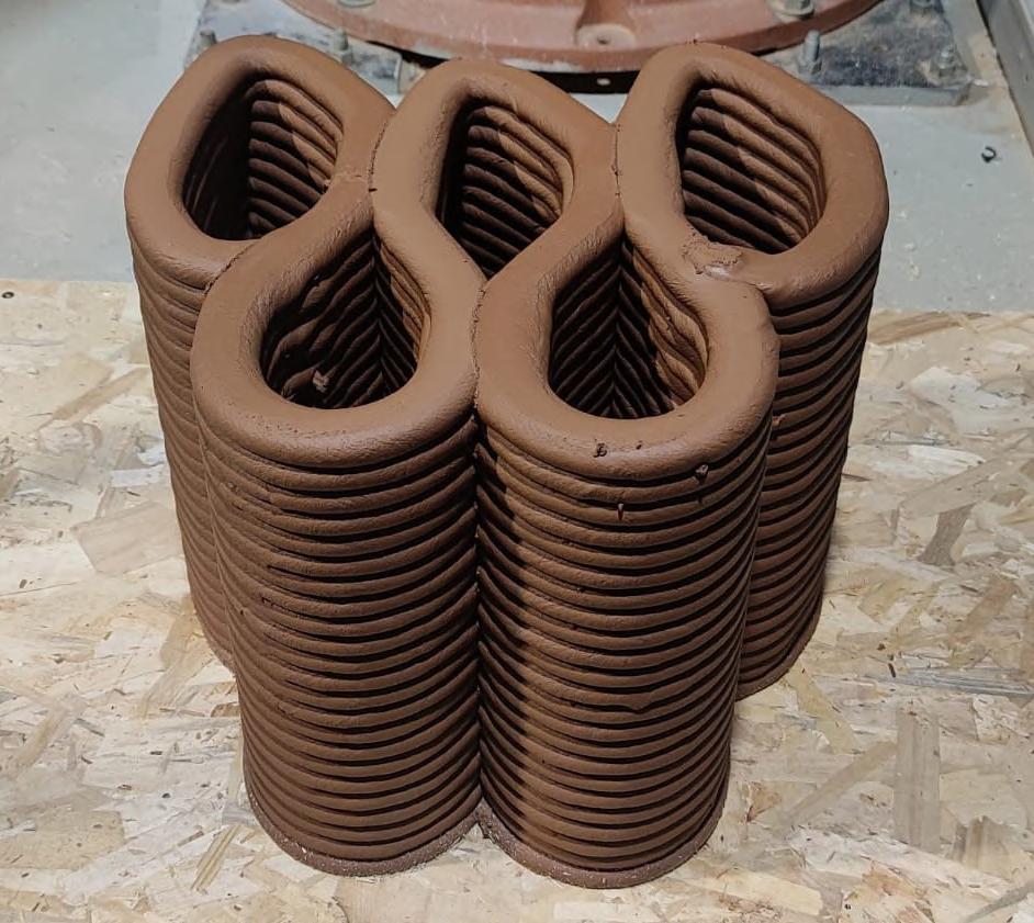
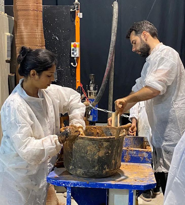
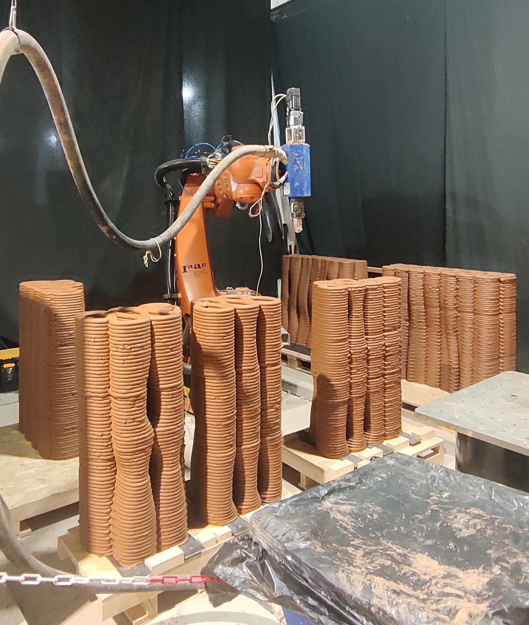 Material feeding to the pump: The earth mix was added to the pump connected to the KUKA end effector (Extruder).
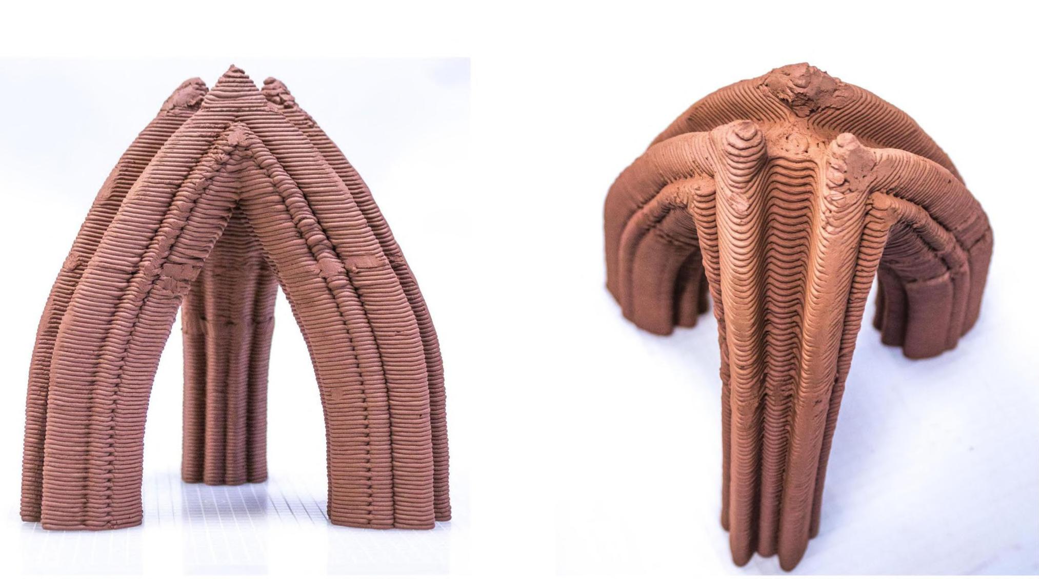
3D printed pieces of the The Living prototype
Living Prototype details
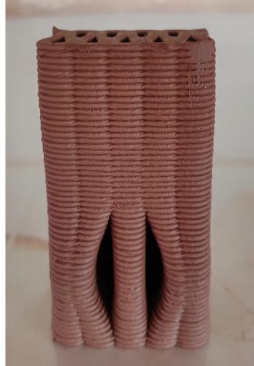

 1:10 scale Roof support anchor detail in the wall - Machine - Ender 3
1:1 scale part printed Roof support anchor detail - Machine: Kuka KR 150
Living Prototype details
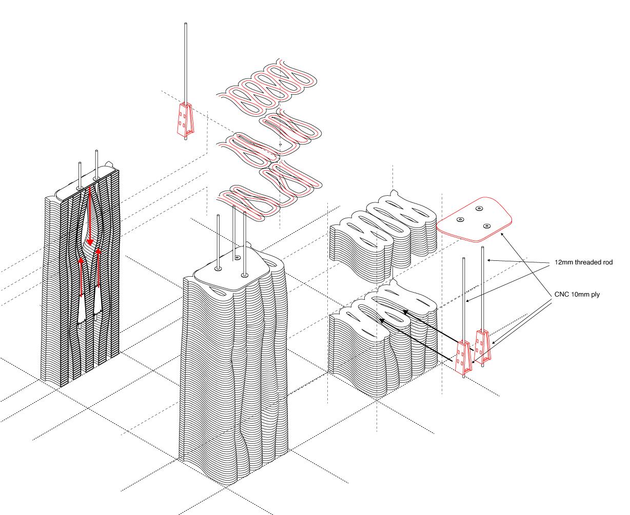
The details were designed to support the Flax fiber weaved roof panels designed by ITKE Stuttgart team.
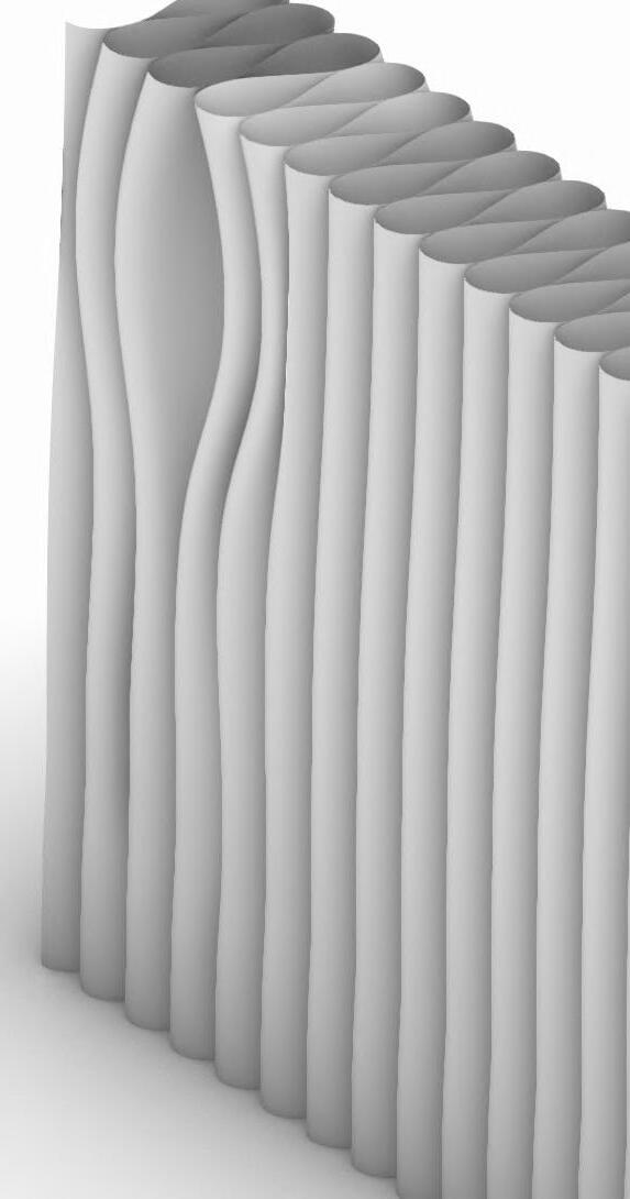
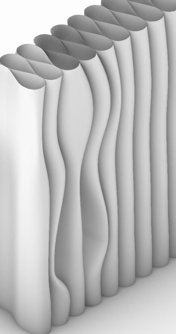
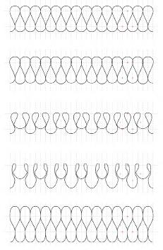
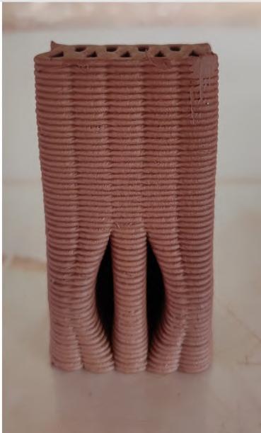
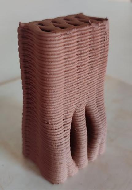


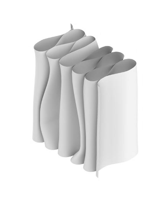
The earth wall was designed to have openings in order to insert the keys those gets locked into the opening and the roof is connected to the metals rods connecting the timber keys.
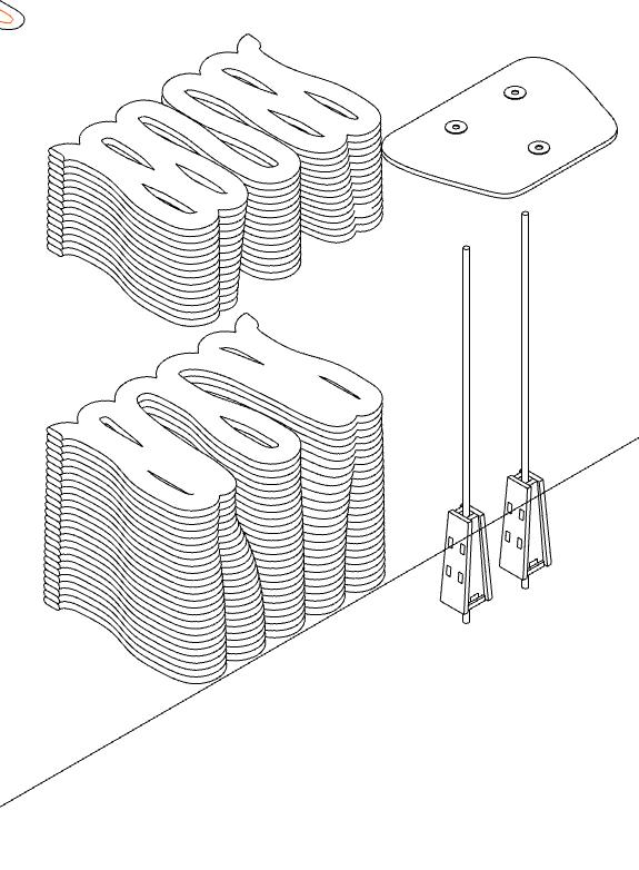
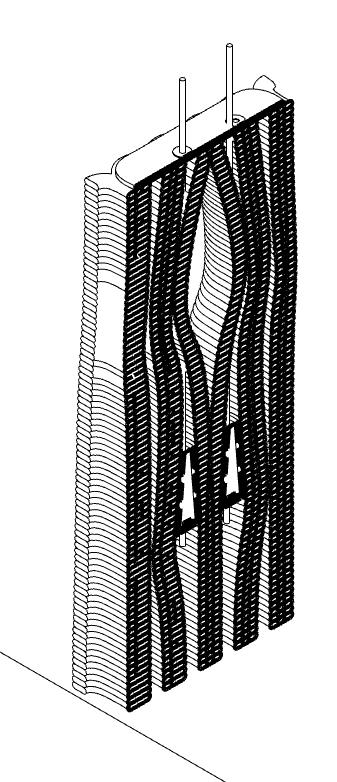 Design of the periods for roof support key
02. Earth 3D Printed Pavilion
An Earth 3D Printed Pavilion:
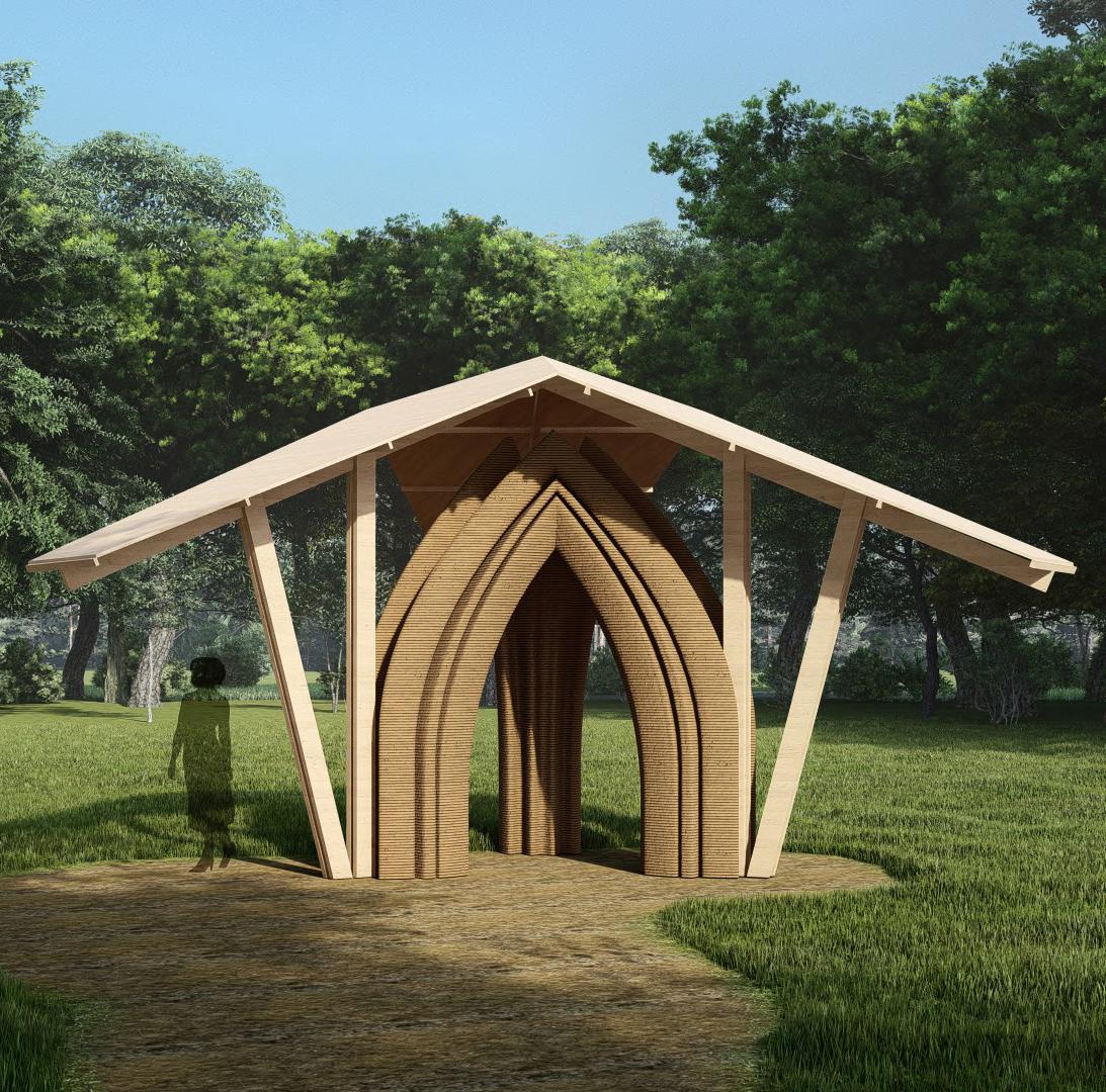
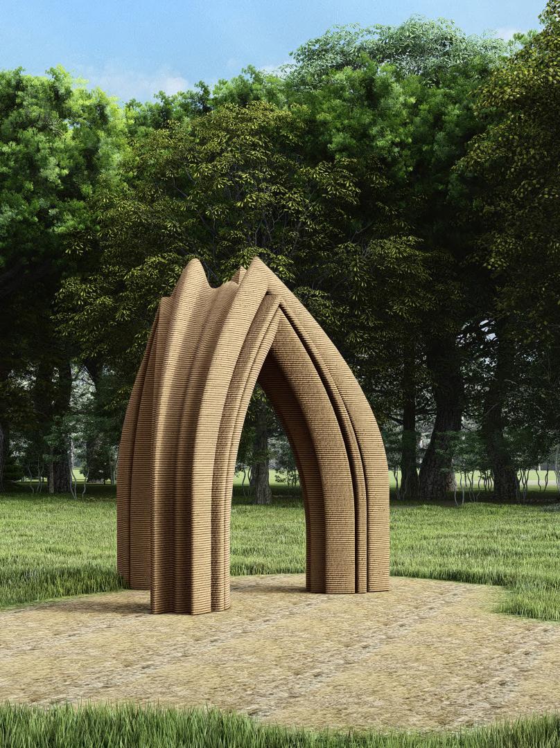
The Earth 3D printed pavilion was to be designed considering a given printing length which would ensure total printing time of 3 weeks.
The design focuses on printing the fifth facade (The overhead printing area) by using the stability through geometrical explorations.
The parameters considered to design this were,
1. Surface Area not more than 56 sq.m.
2. Printing Length - 4800 mm
3. Printing time - 15 days
4. Per day printing target of 20cm
The design process follows bottom to top approach. First step is to design a module which should have a potential to proliferate further to design the larger space.
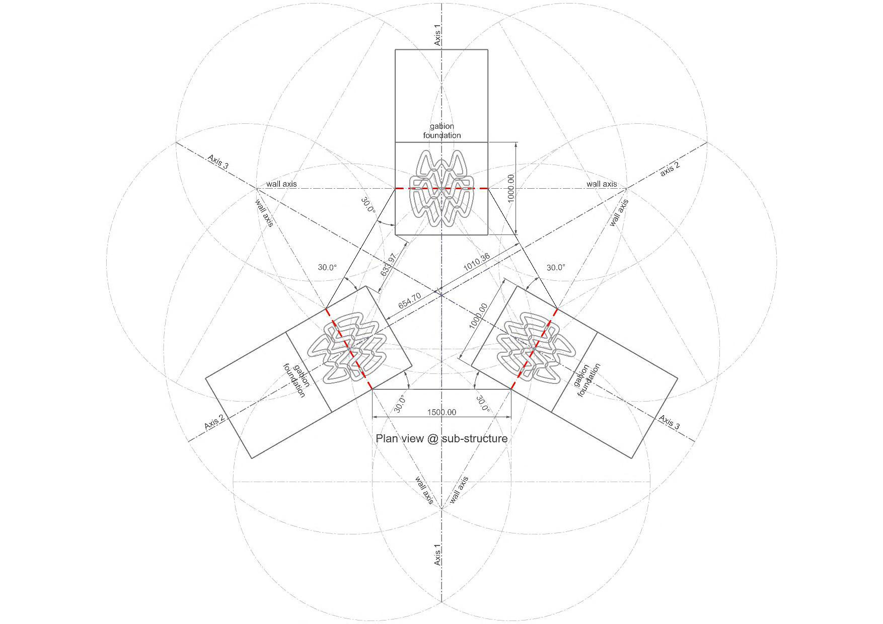
Pavilion plans
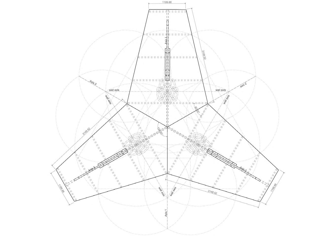

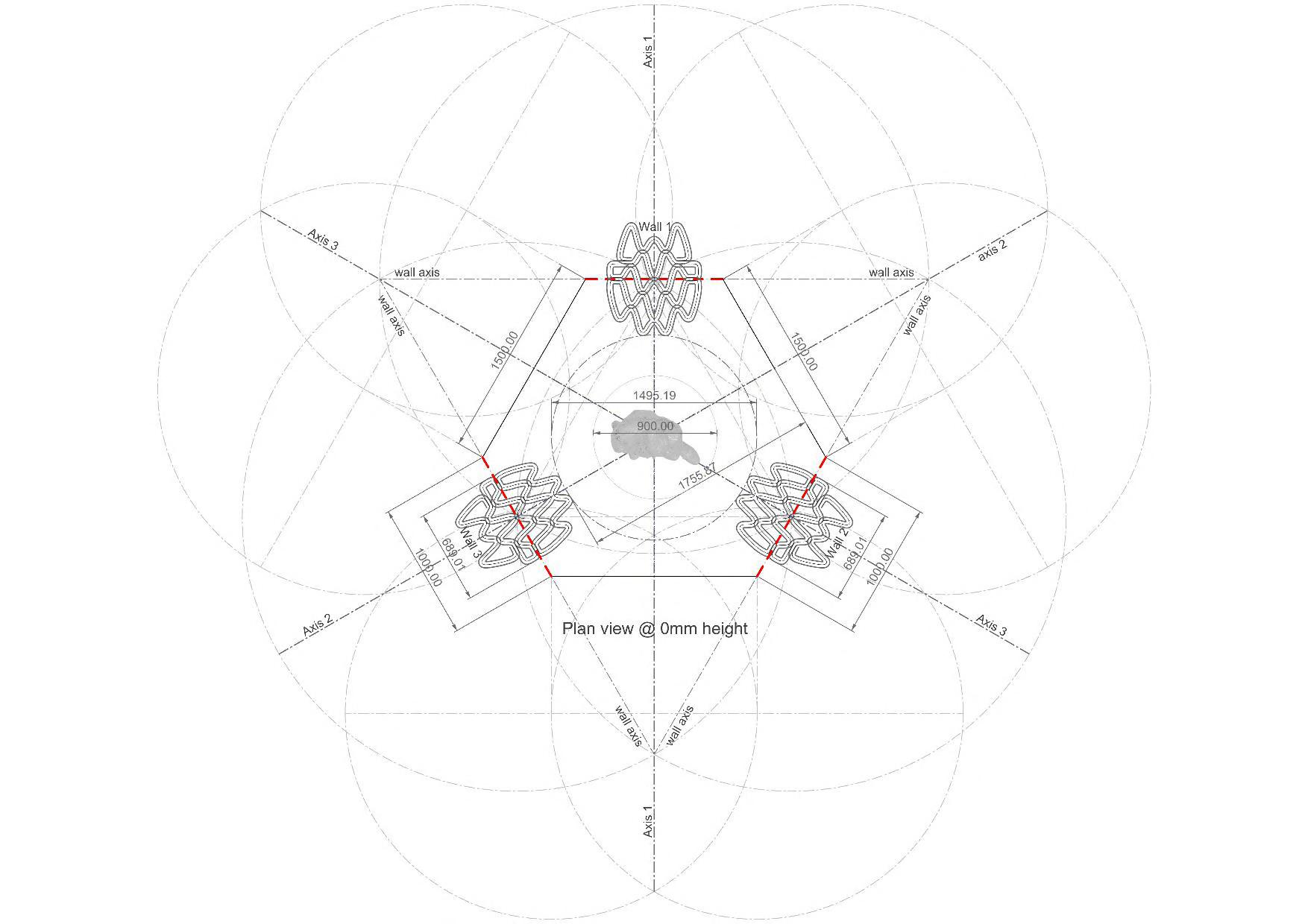
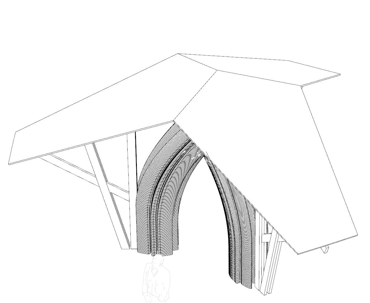
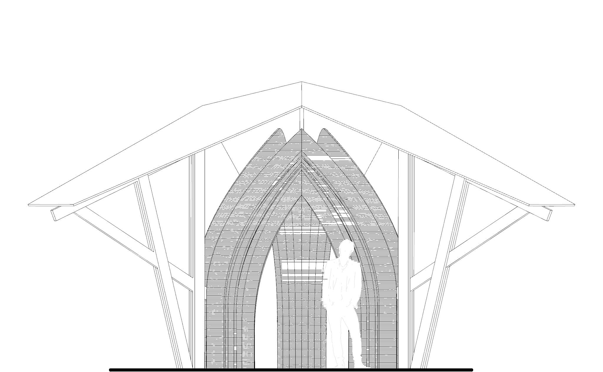
Elevation and views

Optimized fiber placement to support earth 3D printed
cantilever in wet state
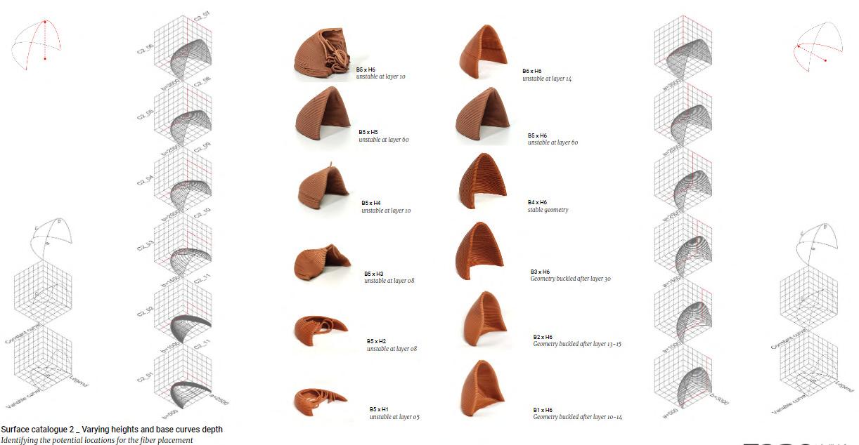
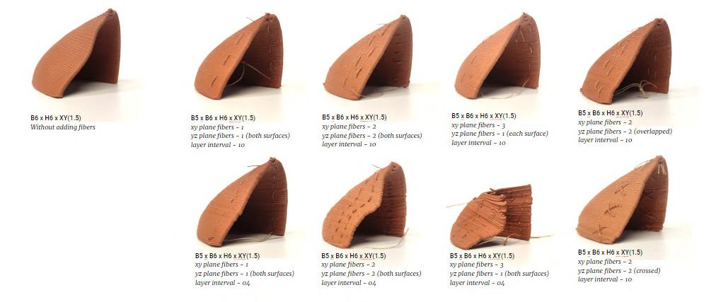
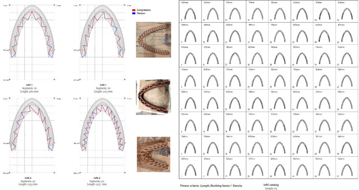
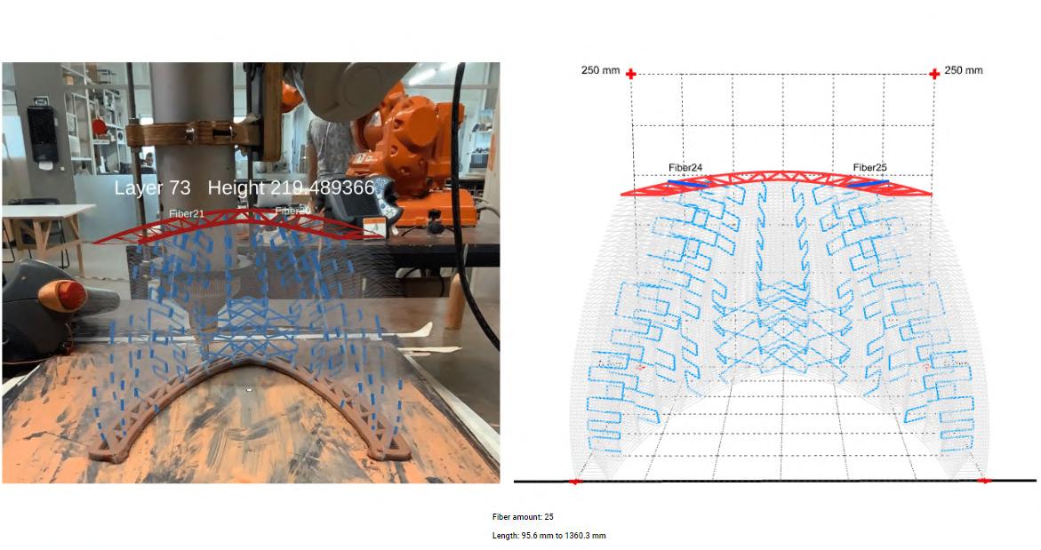
The research aims to take an advantage of the knowledge from the past and integrate with today’s technology to construct novel and complex forms. The intention is to integrate fibers during the 3d printing process to support the cantilevers in wet state as well as find the optimized method to lay the fibers. This method may include the anchor points at various levels around the structure and digital tools to locate the optimized fiber locations and orientations.
The research focuses on the design and fabrication aspect of the optimized placement of fibers, to support the earth 3d printed cantilevers through digital analysis of the geometry, to identify the orientation of the fiber placement and evaluating the most feasible method to add fibers in the wet state during 3d printing.

Additives and fibers have been a significant part of the Earthen mixes, as they provide the necessary strength, binding properties, weather resistance as well as aesthetics to the structure.


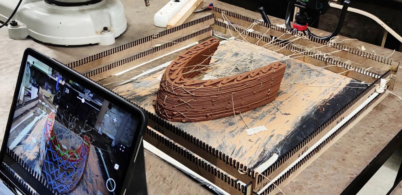

Techne: Workshop at 3DPA IAAC
In collaboration with ITKE Stuttgart.
Multistory building design with 3D Printed earth
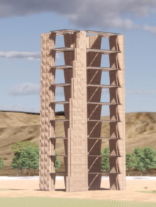
This project was developed in collaboration with the ITKE Stuttgart team. A multistory building of 10 floors was to be designed using the Cellulose panels as the intermediate floor slabs.
The challenge was to design the earth walls with anchoring the cellulose panels designed by the ITKE team. furthermore, the walls were to be placed strategically, ensuring the maximum floor plate area and the stability in the wall.
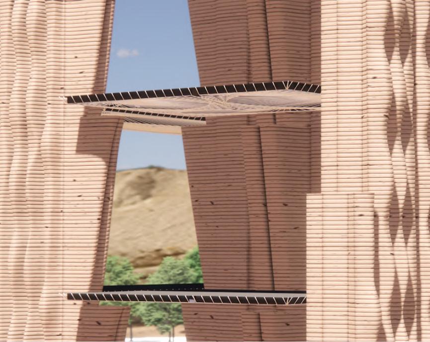
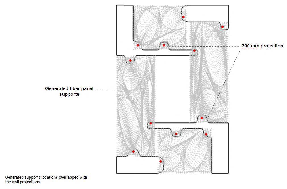

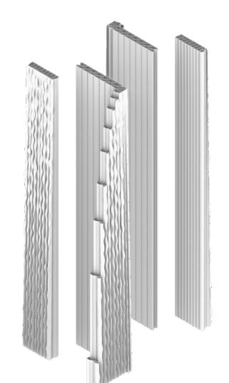
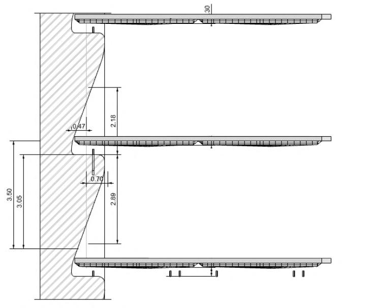 The workshop focused on proposing an Architectural proposal using the Flax fiber weaved panels designed by the ITKE Stuttgart team, as a flooring solution and design the earth walls to support the roof panels.
Proposed typical floor plan
Wall texture
Wall design for 10 floor structure
Typical details of Flax fiber weaved roof panels
Additive Manufacturing Using Lime Mortar - Research &
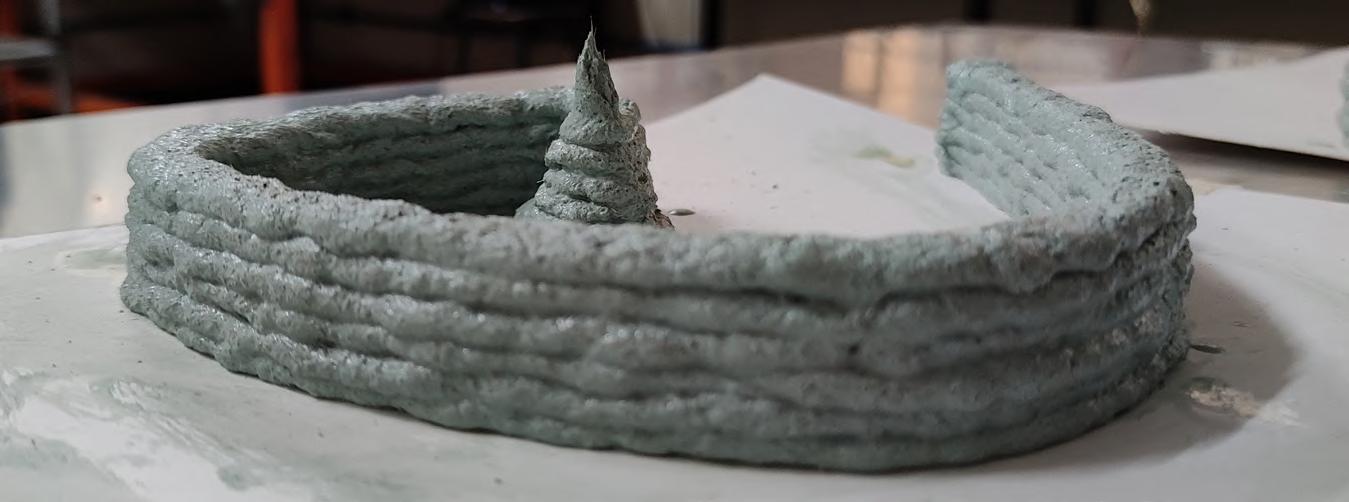
The research focuses on optimizing the lime concrete (traditional Portland cement mix) to suit the additive manufacturing method of construction. A systematic documentation of the lime concrete mixes with various proportions of the ingredients to suit the extruder shall be done to find the most optimized mix.

The use of additive manufacturing technique involves the use of robotic extruder, which speeds up the process of construction.

The use of digital tools is needed for three reasons.
1. To rethink the application method of optimized traditional lime concrete mixes in order to meet the changing demands.
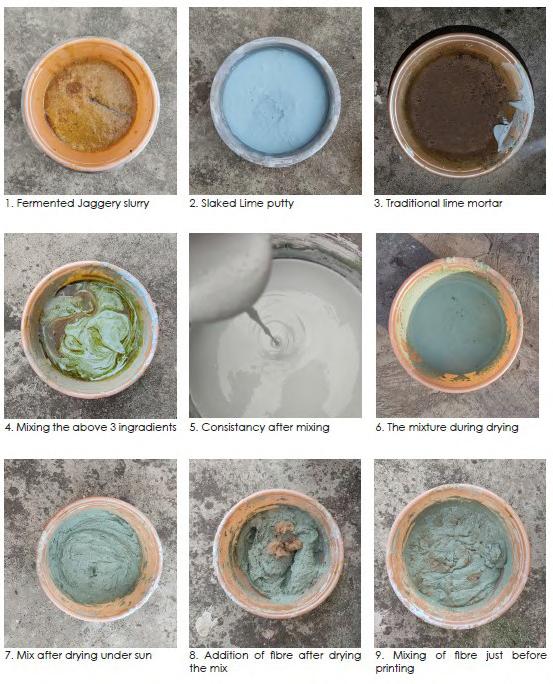
2. To fasten the application process of lime concrete.
3. To explore the possibility of using traditional lime concrete mixes as a monolithic element.
Robotic Extrusion
Mix Optimization
The consistency of the lime mortar prepared with the traditional methods is not suitable for additive manufacturing process due to its value between 25%-35%
The ideal mix for printing needs to be in the paste form which should not break during continuous layering. Also, the printed model should be able to bear self-weight and should not collapse. The mix should also be able to gain the necessary strength after curing. The next phase of this study is to test the model for its compressive strength.
Mix 9 Day 4
Slaked quick lime 200
Power quick lime -
Jaggery paste 25
Jaggery water -
Fiber 20% of the mix volume
Analog Experiment Results
1. Chakli MakerAnjali Brand nozzle size7mm
constant 1. Mix 7 = Mix 5/2 + 200 ml slaked lime
2. Mix was extruded without breaking until the pressure was changed
Variations in Atmospheric condition during successful Analog extrusions
Analog extrusion experiments:
The analog extrusion experiments were performed under the following average atmospheric conditions
Average atmospheric conditions on 14th Nov. 2021 between 8.30am - 17.30pm
Temperature: 28.75 °C
Relative Humidity: 61 %
Atmospheric Pressure :1008 mbar
Weather: Clear-Partly Sunny-Overcast The mix was prepared, dried and extruded outdoor.
Key Observations
Lime Mortar 100 <5mm 4 11am4.30 pm temp - 32 -29 deg.
Power quick lime -
Jaggery paste 25
Jaggery water -
Fiber 20% of the mix volume
Mix 9 - Samples
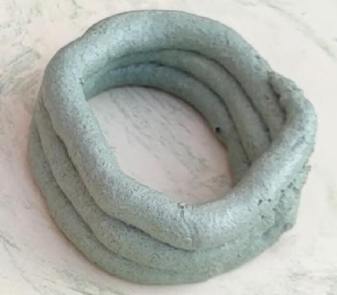
Model printed with mix 7
Nozzle size - 7mm
Small nozzle disturbed the continuity and control over laying the layers.
1. Chakli MakerAnjali Brand nozzle size7mm
Constant 1. It was difficult to extrude since the fibers were getting tangles at the nozzle frequently Slaked quick lime 400

2. stainless steel icing piping nozzle attached to the icing bag
nozzle size1cm dia.
Varying 1. The mix was extruded smoothly without breaking even after
a. changing the pressure
b. frequent back and forth motion of the icing bad during extrusion
Mix 9-14 Nov. 2021 14.30 hr.
31 °C
56 % Humidity
Atm. Pressure 1006 mbar
No water dripping was observed during extrusion
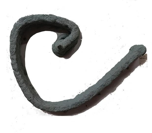
Model printed with mix 9
Nozzle size - 15mm
Bigger nozzle size ensured the continuous extrusion
As the quantity of jaggery water increases, the hardening of the mix fastens.
After addition of 5% of jaggery water, the mix dried up during the mixing process. Hence, after trying out various quantities between 1%-5%, 2.5% of jaggery water was finalized as the final quantity to be added. also, the successive layers were dried enough to take the load of the next layer
Robotic Extrusion Results
The
allowed the mix to come out of the
The
Variations in Atmospheric condition during successful robotic extrusions
Robotic extrusion experiments:
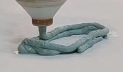
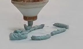
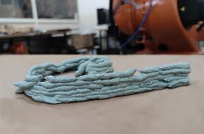
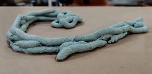
The robotic extrusion experiments were performed under the following average atmospheric conditions
Average atmospheric conditions on 3rd Dec. 2021 between 8.30am - 17.30pm
Temperature: 23 °C
The
the
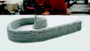
change in the geometry from curvilinear to more linear continued the mix to break after 3”-5”
Change in the pressure to 2.7 allowed the mix to be extruded in continuation without any break
Mix was extruded without any break. (Break during laying 2nd layer due to controller handling error)
Relative Humidity: 89.5 %
Atmospheric Pressure :1012.25 mbar
Weather: Fog-Overcast-Light Rain-Passing clouds
The mix was prepared, dried and extruded indoor.
Conclusion
Traditionally used lime mortar mixes are time tested and have proven their strength and durability which can sustain for centuries and more.
Mix behavior due to drastic change in atmospheric conditions:
1. Due to the presence of jaggery water, in the above weather conditions, the water couldn’t dry to its necessary ratio. Also due to the excessive humidity, the mixture absorbed moisture from the air which caused dripping throughout the printing process.
No deformations were observed after the printing was done. The picture was taken one hour after the model is printed
This research has experimented and studied the behavior of optimized lime mortar mix suitable for additive manufacturing process.
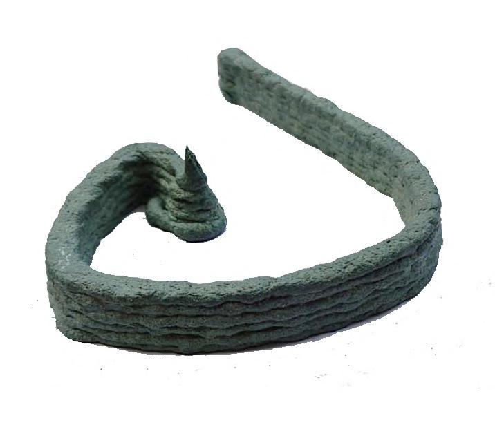

Various proportion of additives were tested to find the right mix for additive manufacturing process.
After gaining the required strength through carbonation process, the model shall be tested for its compressive strength.
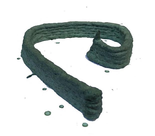
The next step of this research would be to measure the setting time of the lime mortar and increasing the carbon dioxide source without changing the properties of the mix needed for additive manufacturing process.
This shall reduce the setting time of the lime mortar enabling it to be eligible for the rapid building processes.
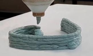
Product Development: Form work to cast the concrete
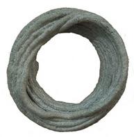
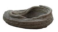
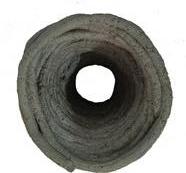
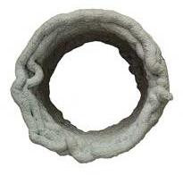
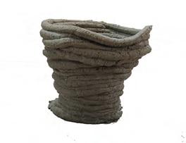
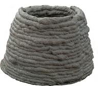
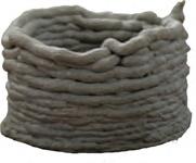
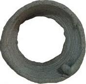
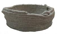
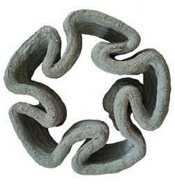
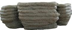
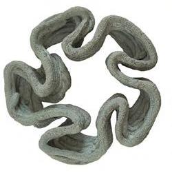
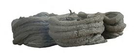
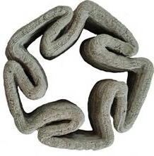
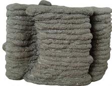
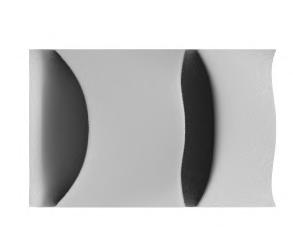
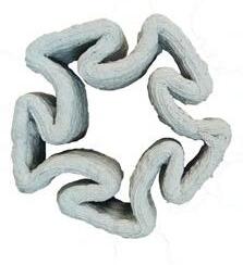

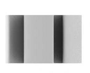
With the increasing demand for housing and infrastructure, material demand will increase exponentially. Such demands put massive load on the supply of resources. As a result, exploitation of the natural environment has been worsening the quality of environment day by day. The study focuses on making prototypes of the form-work using lime concrete. Considering the initial strength of the material, the wall sections shall be designed in such a way that the printed layers will be able to take the force exerted by the poured concrete.
WHY LIME?
Lime follows a natural cycle where with carbonation process the slaked lime turns into calcium carbonate, where the process ends and starts again to form a cycle.
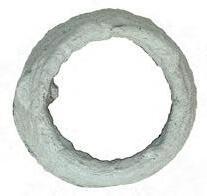
PROTOTYPE DESIGN RATIONALIZATION


PROPOSED PROTOTYPE DESIGN

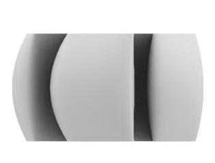
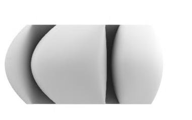
Layer thickness variation due to variation in base geometry curves
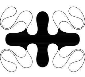
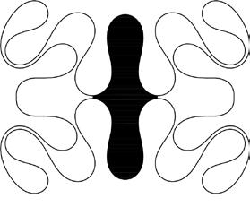

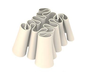
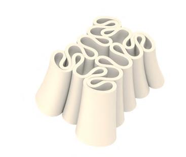
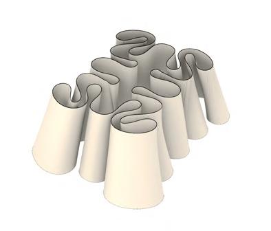
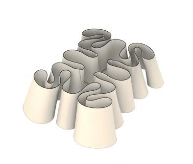
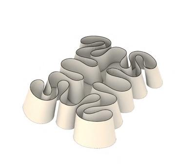
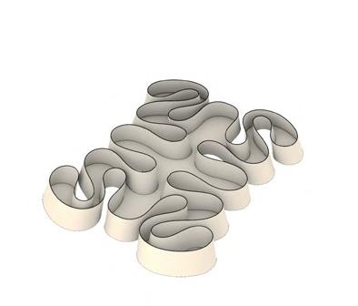
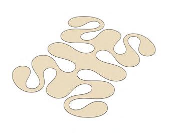
CEMENT CONCRETE CASTED IN THE DESIGNED FORM-WORK PRINTED WITH LIME CONCRETE MIX.
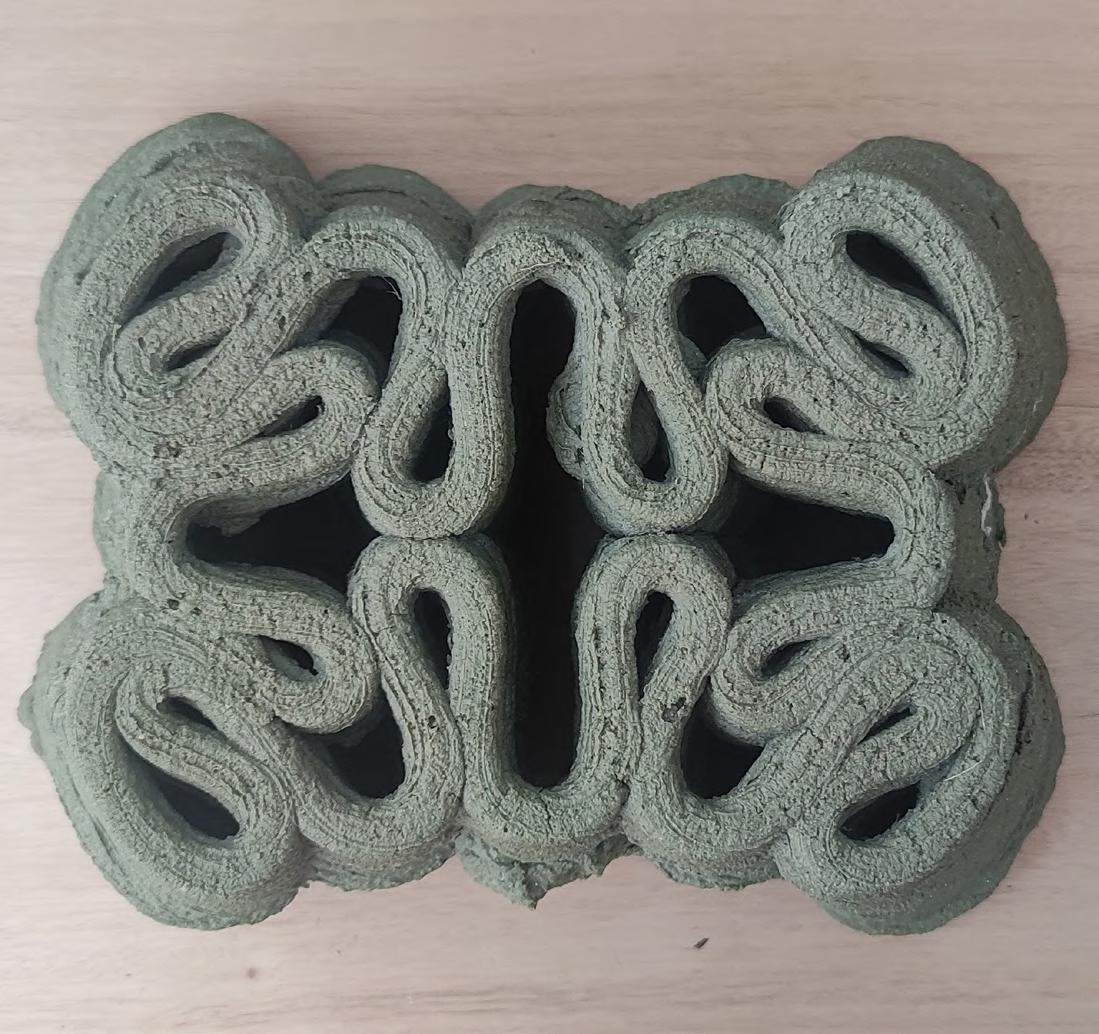

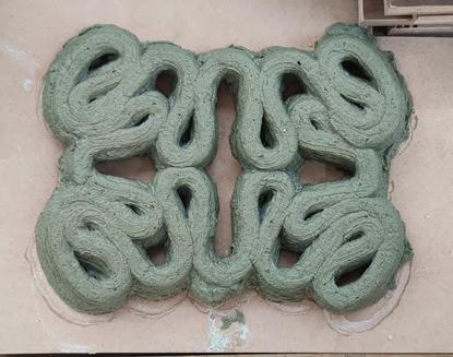
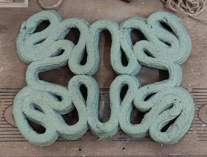

Cement Concrete casted in the Cylindrical Formwork. The 3D printed layers are loosely laid


Cement Concrete casted in the Corrugated Formwork. The 3D printed layers are well compacted
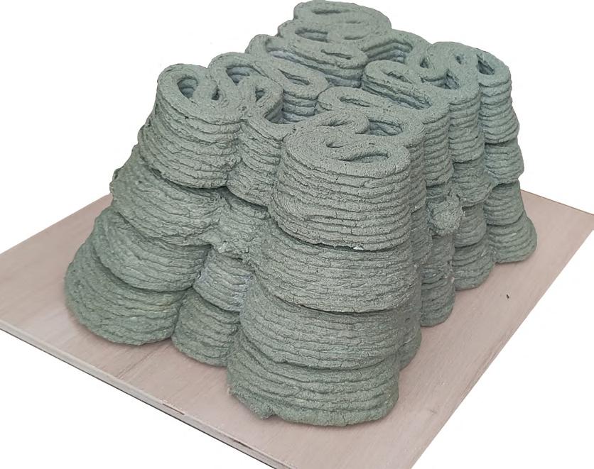

Urban Design is an expression of the needs of human beings in the form of built infrastructure at that span of time, While Serving to these needs and demands, the sensitivity towards the natural environment is being ignored. Which has eventually resulted into creating a highly polluted natural as well as built environment. This has become quite intense since a last couple of decades. The result of which is depletion of our natural resources, d degraded lifestyle and loss of biodiversity.
All these factors directly or indirectly affect the accessibility to the fresh and healthy supply of Food and Water. Rapidly growing urban areas are the first ones to get affected. Hence, it is important to rethink the design and planning strategies for the existing and upcom
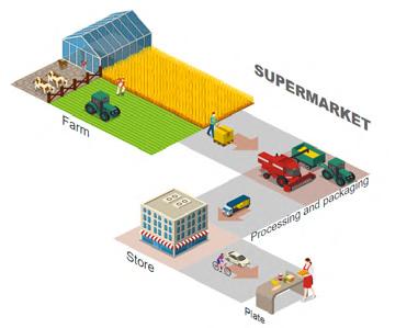
ing urban areas.
Design Parameters & Evaluation Criteria
Length of Road between Branches
Minimum - 500 m
Maximum -1000 m
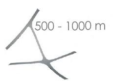
Road Network
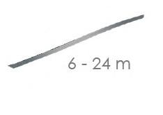
Road Width as per Length
Minimum - 6 m
Maximum - 24 m
Build-able Zones Closest from town/city core
town/city
core
Branches At the Nodes
Minimum - 2 Branches
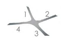
Maximum - 4 Branches
Contributions to the team: 1. Conceptualization - 90%
2. Data extraction - 20% 3. Data sorting and finalization - 90% 4. Logic Building - 100% 5. Computation - 100%
TEAM - AKSHADA ANAGALI l DNYANESHWARI METE POOJA YADGIRE
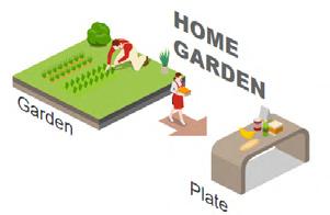
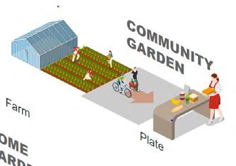
Farm To Table Concept

Distance (maximum) From Residence to Green space: 200m
Local Amenities :150 - 400m
Urban green space: 80 - 30 sq.m./person
Ratio of-built to Unbuilt: 1:4>

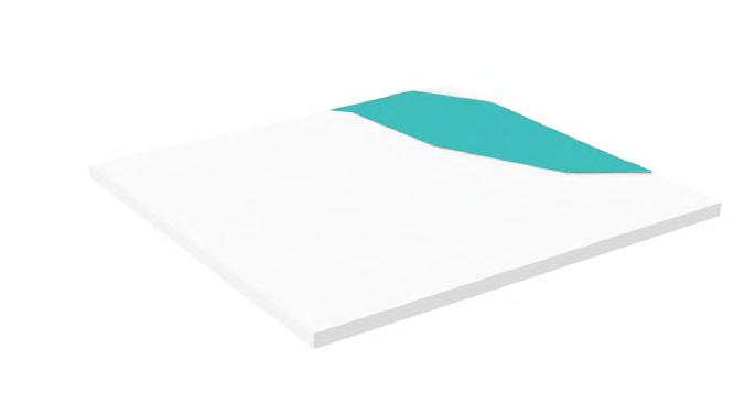
Preparing the existing landscape of various locations - Base Map for the Designed System application
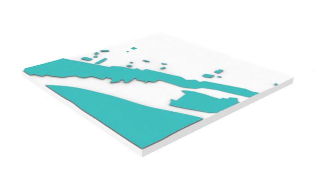
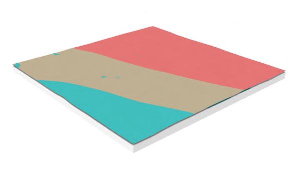 BUTWAL, NEPAL KOCHI, KERLA KUTCH, GUJARAT
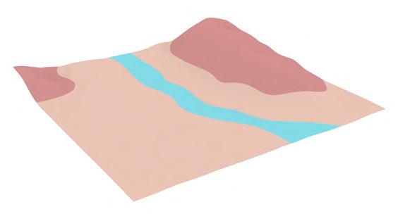
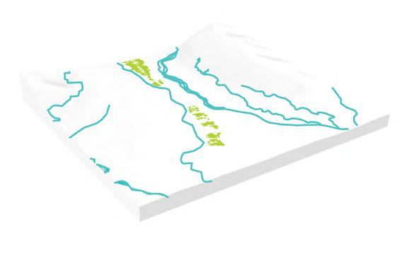
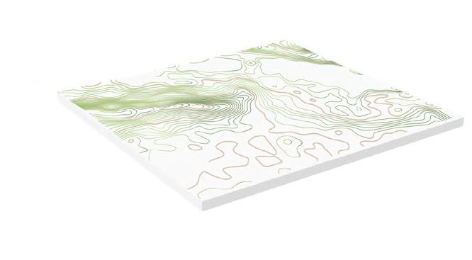
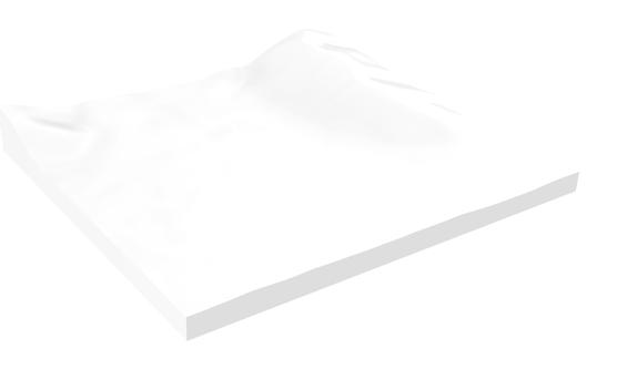
Existing Topography of the Raigad context for the process of System Design
Existing River and the Forest as part of the Natural landscape
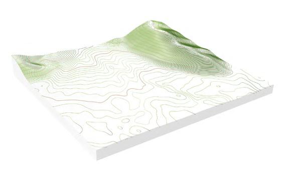
Major and Minor Contours as part of the Natural landscape
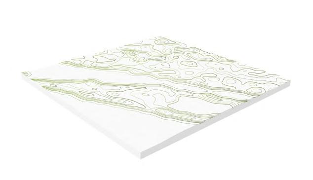
Major and Minor Contours as part of the Natural landscape

Highest Point Lowest Point


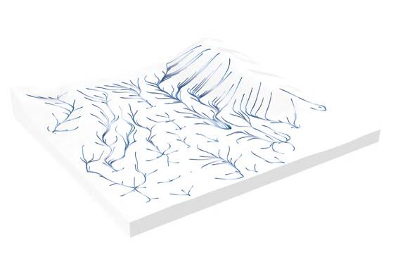
Water Flow Analysis to identify the lowest elevation areas which could be treated as the potential Rain water catchment areas to serve as Soak pits or Ponds/Lakes

Soil Texture map of the Natural Landscape
Closest Proximity of the food supply markets from the food production places and habitable spaces (Person)
Food supply markets
Habitable spaces
Existing greens
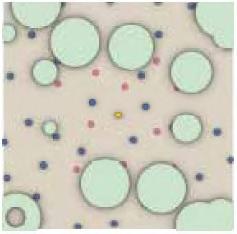
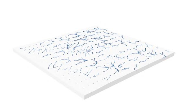
Person template Emitter Points considered for the agent based-modeling

Habitable spaces as Emitter points

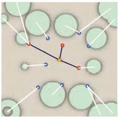
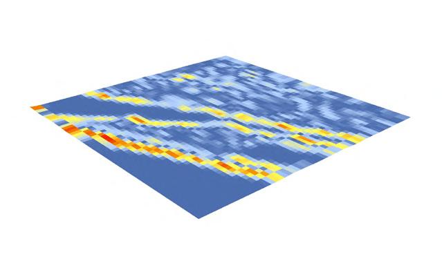

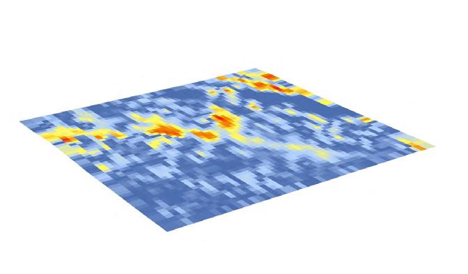
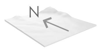
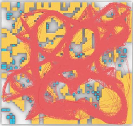
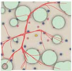
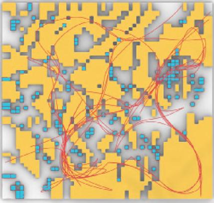
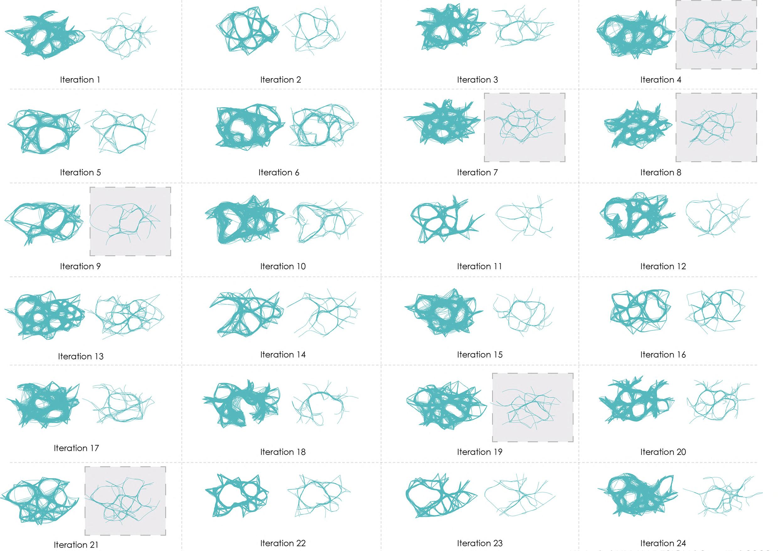
Generated Primary Road Network - Single Node
Road network
Generated Primary Road Network - Multi Nodal
Water harvesting areas
Proposed greens
Buildable areas
Road network
Simplified Road Network
System Design Application - Faridabad, India



The aim of the chosen system design is to ensure the supply of fresh food and create a carbon neutral urban cities and spaces. Also healthily accommodate the growth of the adjacent megalopolis.
To achieve the same, we chose the city at the periphery of the megalopolis so that the existing ecosystem shall pe protected, also the new proposals are designed in a way that they respect the biodiversity and help to address the current environmental and eventually health issues.
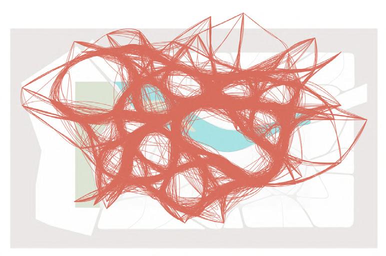
Primary Road Network iteration overlapped on the existing site natural elements

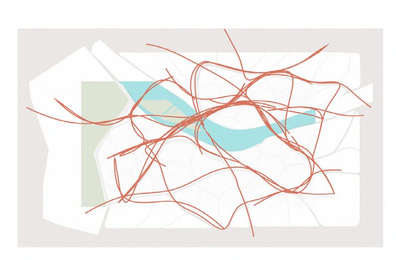

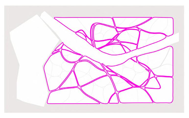
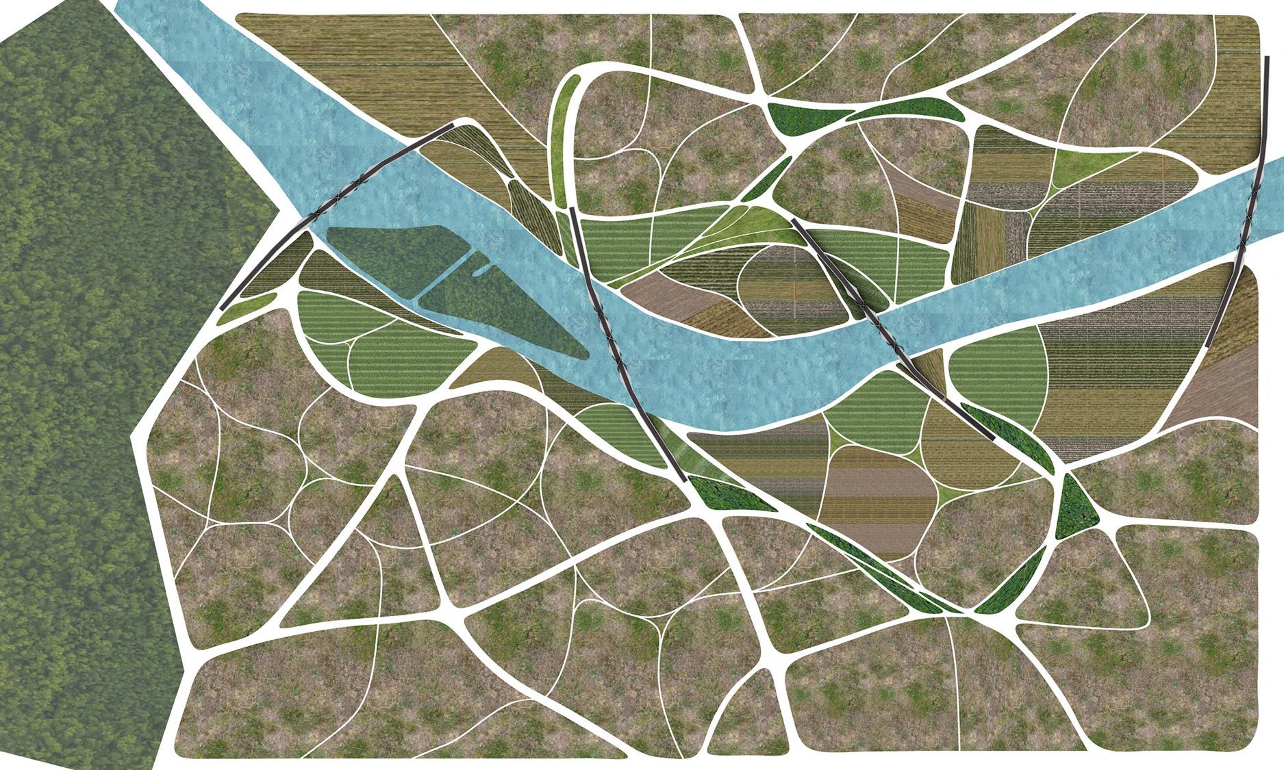
Simplified Road Network in order to get clearer land partitions
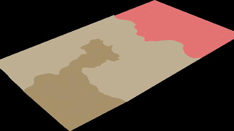
Water Flow Analysis to identify the lowest elevation areas which could be treated as the potential Rain water catchment areas to serve as Soak pits or Ponds/Lakes
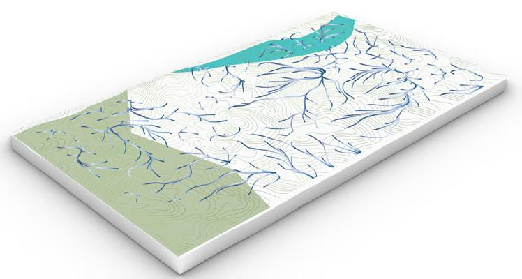
After the water flow analysis, potential areas around the lowest elevation points to be converted into the catchment areas and the land around them to be dedicated to the Major Urban Green Spaces
Generated Primary Road Network Grid
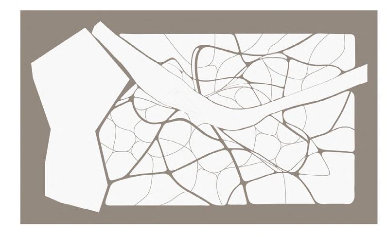

Generated Secondary Network


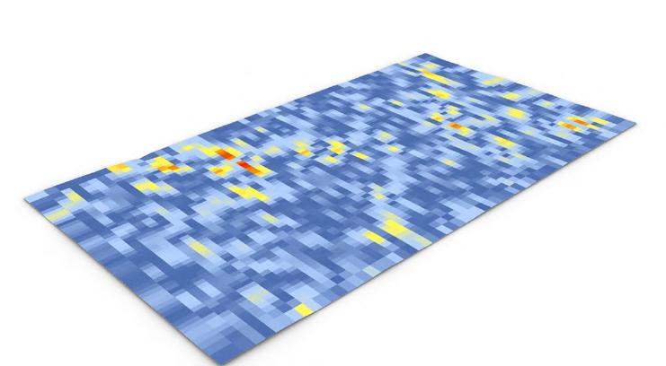
Road Network
Generated Primary and Secondary Road Network Grid

Zones
Urban greens plus habitable spaces

Farms plus residences
Food and resource forests







Natural forest
Range of zone
0.4 - 0.6 sq.km
0.2 - 0.4 sq.km > 0.2 sq.km -
Road Network Development - Primary Road Network Iterations
Selected iteration as per evaluation criteria
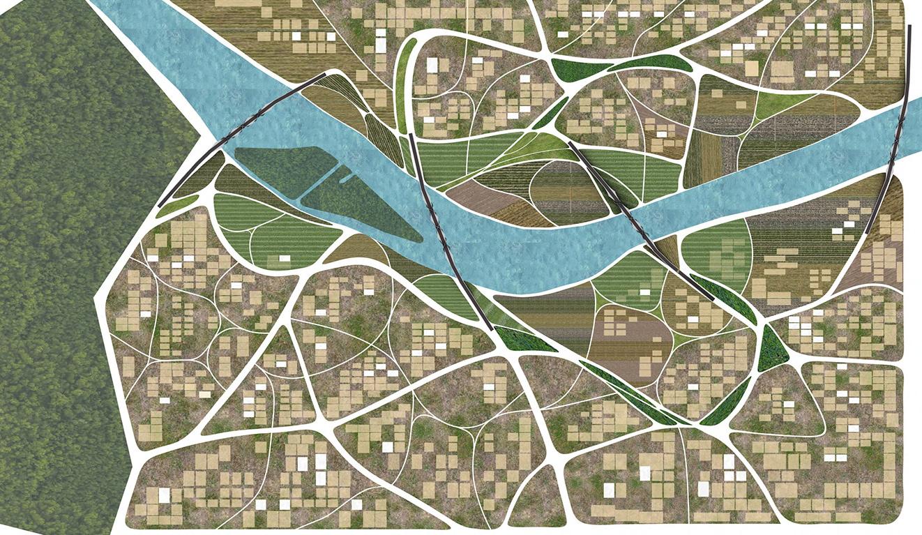
Site Plan and Views
Future Scope
Site Plan showing the proposed built spaces and Dedicated Farmlands
1. Restricting the man-made infrastructure on ground (e.g., roads, pavements, any floor plates shadowing ground etc.
2. Choosing right building materials to create suitable atmosphere for the urban farms adjacent to building facades
3. Living in harmony with the co-created condition due to increased vegetation.
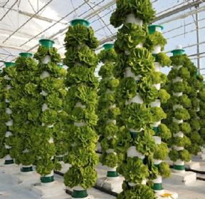
Vertical farms for sustainable food production

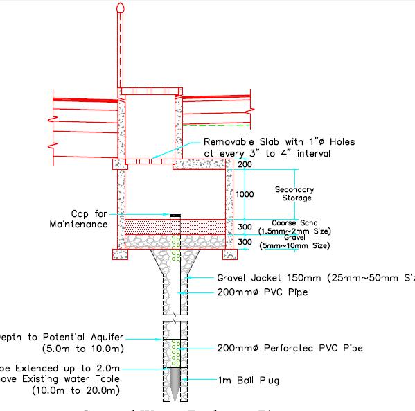
Decentralized wastewater treatment system with the vortex system as water energizer and landscape element
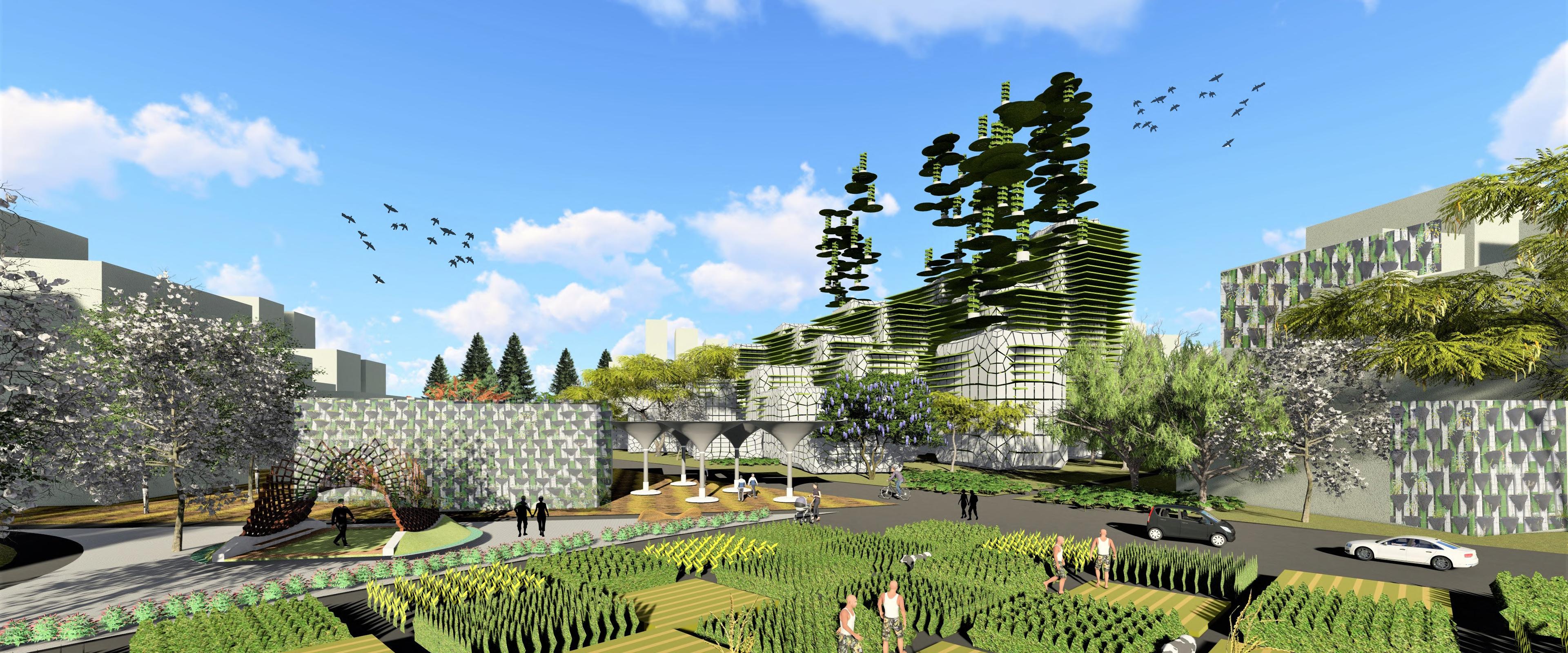
Building cluster view showing the balance between built and green spaces
4. Use of technology as farming assistant while making sure that the e-waste is being generated in controlled manner or disposed safely.
5. Inspecting the climate and weather change as we go higher
6. Identifying the challenges for farming at higher elevations and creating necessary suitable conditions
7. Management of the landfills to treat hazardous waste
8. Opportunities of the production of biofuels
Site Section and Views
Natural water resource is used for farming and habitable spaces
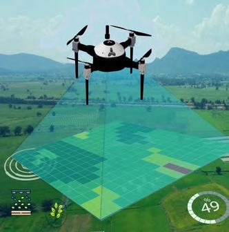
Drones to optimize agriculture operations, increase crop production, and monitor crop growth
Wind Energy on taller buildings

Vertical Farms will be essential for food production in a sustainable way


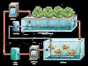
Hydroponics, aquaponics and aeroponics
Recreational Spaces near farmlands lead to more productive sales and job opportunities
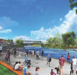
Trees can provide food, shadow and increase biodiversity also help to reduce heat island effect and pollution level.
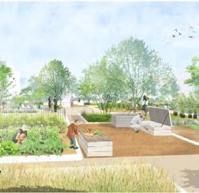
Roof Gardens can be used for food production, temperature control, Hydrological benefits, architectural enhancement, habitat for wildlife and recreational opportunities
Renewable energy production through solar Panels
Water catchment Area above ground to collect water at less ground surface
Less fuel consumption and Carbon footprint
Vegetable Gardens for food production, enhancing a sense of community between citizens of each neighborhood
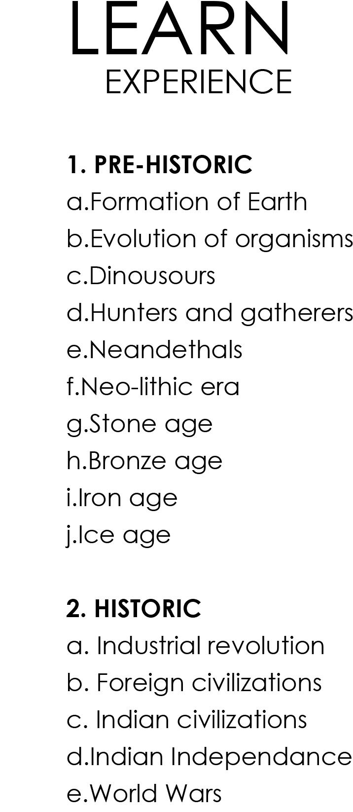
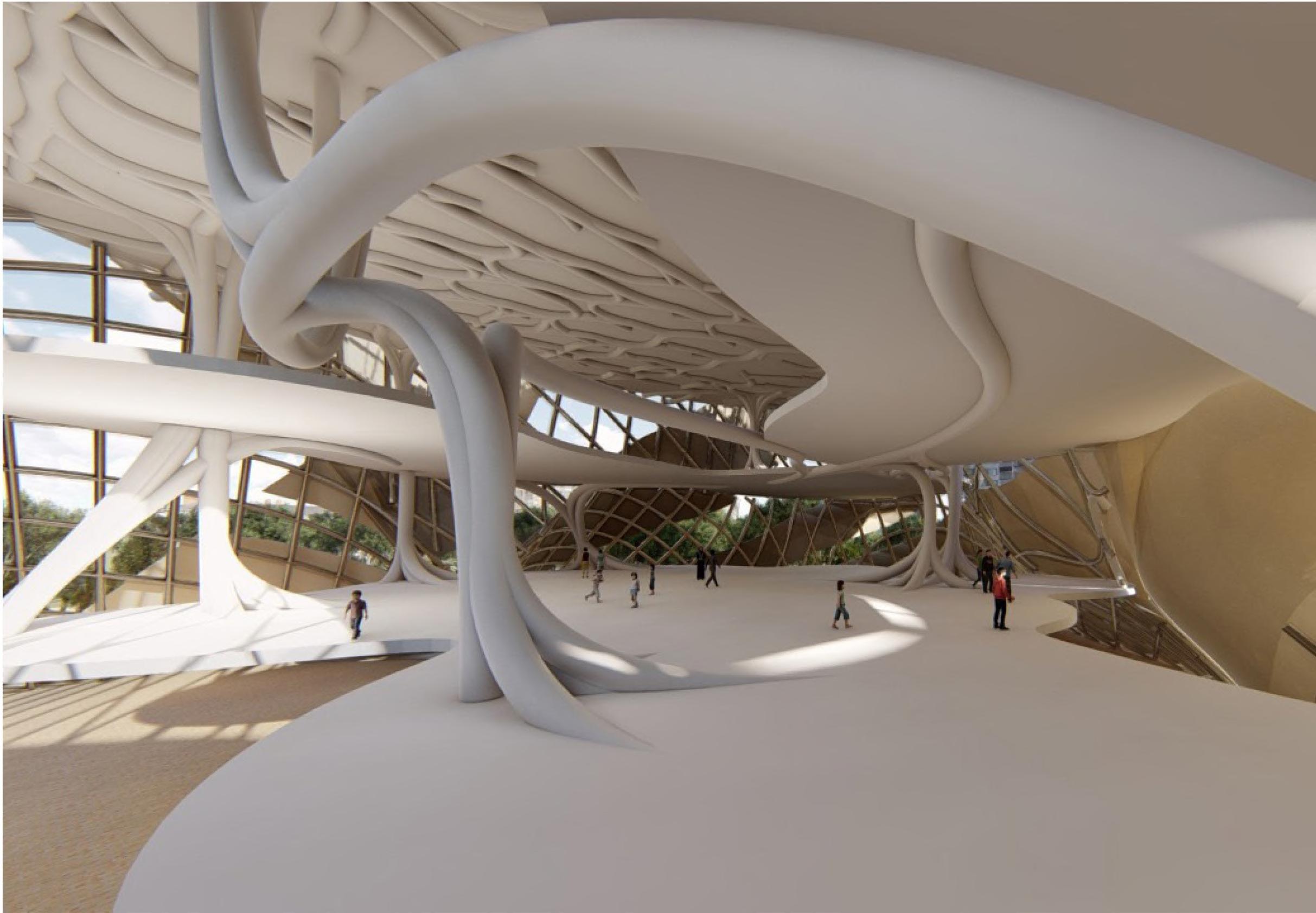
In the world of digitalization, the real-life experiences have faded. Extended reality has become an new reality. Upon this, pandemic has brought on isolation with it, which further narrows down the outer space experiences and knowledge. So, the proposed experience park comes up with these experiences which can be felt even in the indoors. This is not only meant for entertainment purpose but can also be used by students, professionals and enthusiasts to experience what they have learnt or want to learn through these experiences.
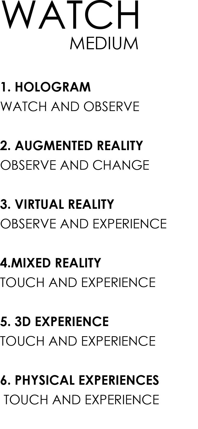
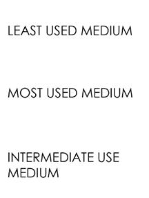
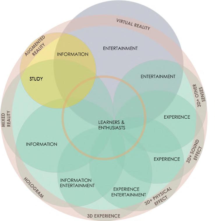
Multi-functionality has become one of the essential parameters to be considered while designing in post pandemic phase. The Experience Park is proposed with various experiences to drive learning through different mediums. Extended reality which includes AR, VR, MR and Hologram will be used to take visitors through the experiences. Dendrite systems was considered as a structural design agency to facilitate the design. The focus in the building would be experiences from Historic and Pre-Historic era which will coincide with the design agencies. Large volumes, glass facades, larger than life experiences and transition in the volumes creates an awe.
Re-thinking of the conventional experience and exhibition centers with regards to the backdrop of pandemic is an approach towards the design process.
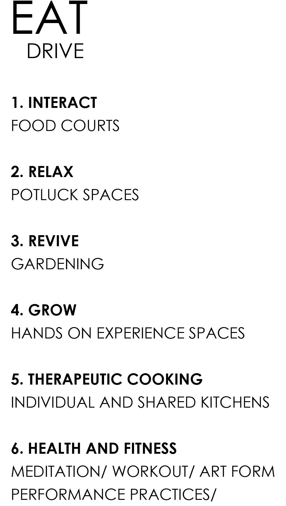
Keywords: Eat-Learn-Watch
Every team was given a set of keywords and any three words were to be selected in order to form the design brief responding to the title ‘Future Flows’
Our team selected the following three words, which upon several group discussions were converted into a design brief of Experience Park of the Future.
Contributions to the team:
1. Conceptualization - 80%
2. Data extraction - 20%
3. Data sorting and finalization - 50%
4. Logic Building - 90%
5. computation - 60%
6. System Design - 85%
7. Proposal Narrative writing - 100%
8. Rhino Modeling - 50%
9. Graphics/Diagrams - 85%

10. Rendering and editing - 5%
Design Parameters
1. Uni-directional circulation to direct crowd in one particular direction.
2. Visual connectivity of spaces.
3. Controlled environment for various experiences.
4. Trail of experiences.
5. Time travel with timeline.
6. Longer side of structure facing north.
7. Planning proximity from entrance.
8. Height of context buildings.
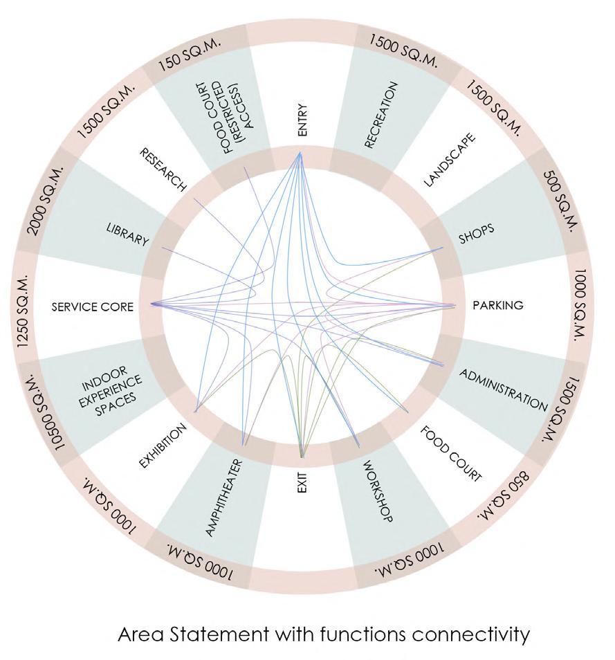
Function Connectivity and Area statement
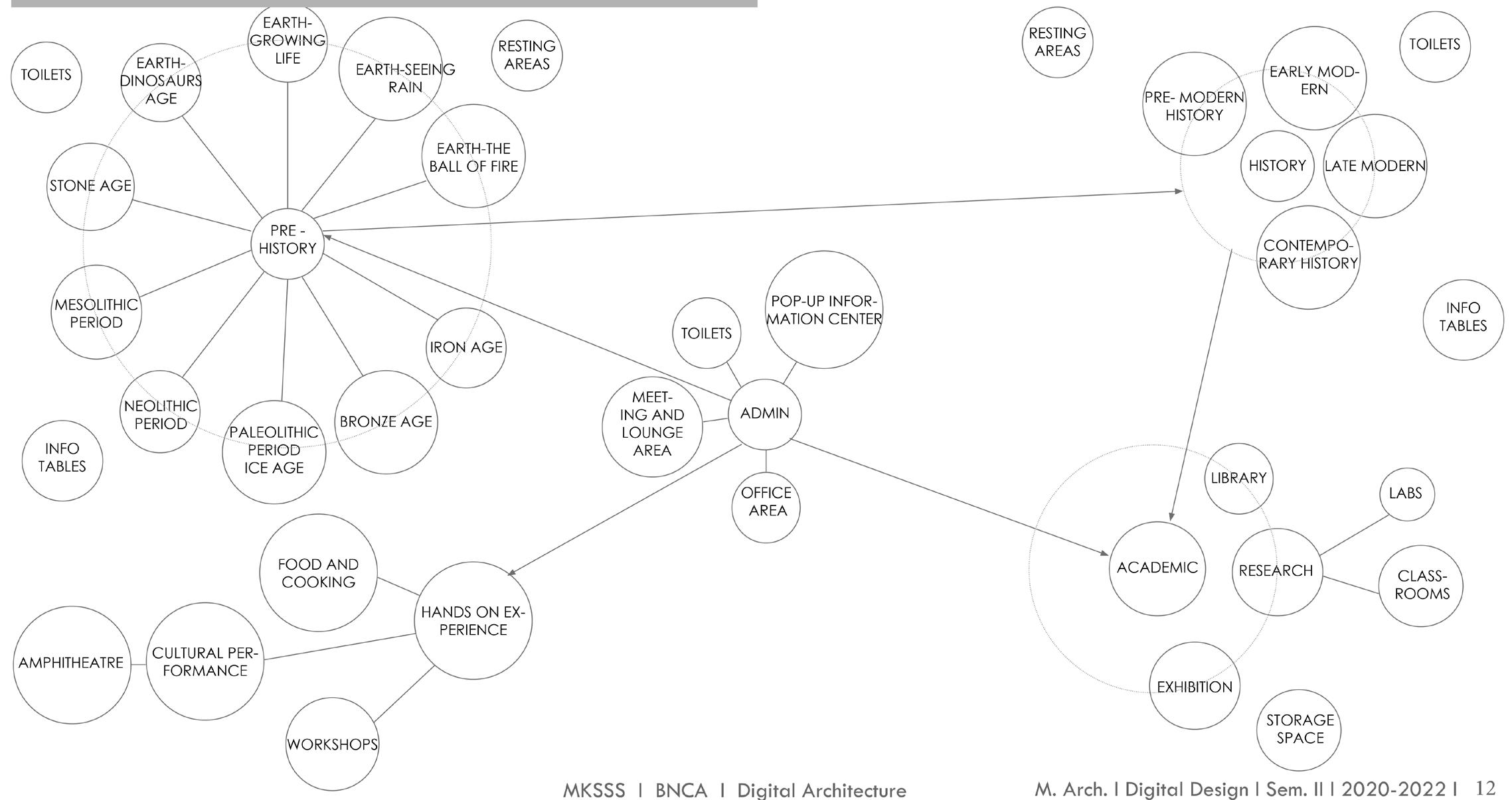
Primary Connections
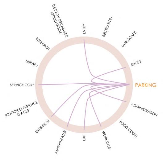
Secondary Connections

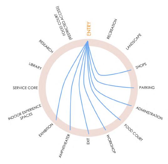
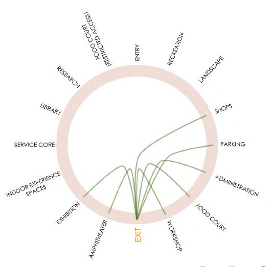
Interior Visuals - Intermediate Floor
FABRICATION -
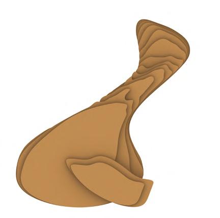
chair - Contouring technique
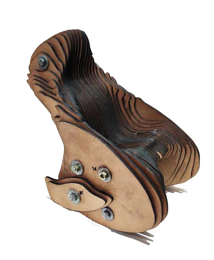
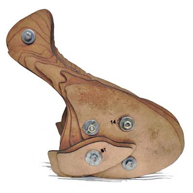
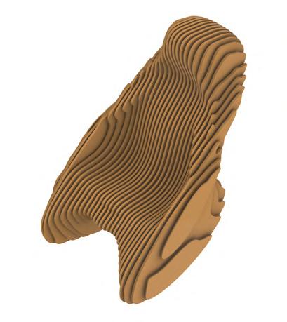
Material for Prototype (Scale 1:5)
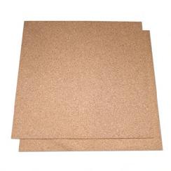
Particle board - 3.5mm thick Standard sheet size 8’x4’

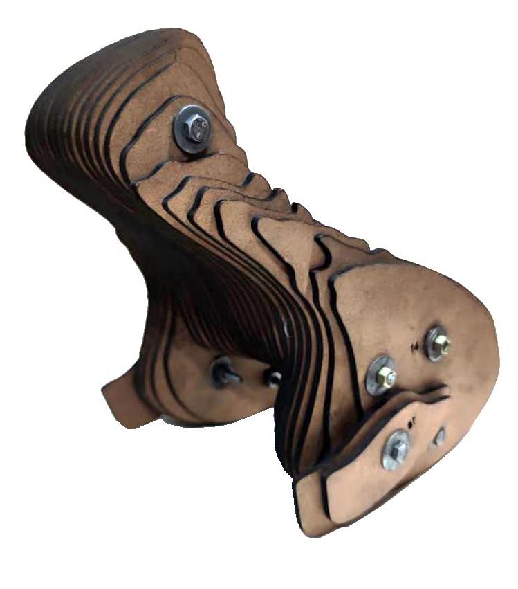
Threaded rod with Screws as connectors Metal wiser as spacers
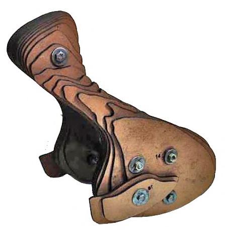
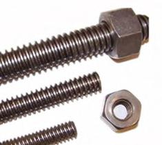
Material for the 1:1 chair
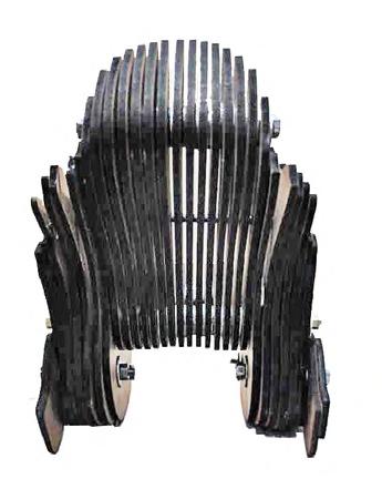
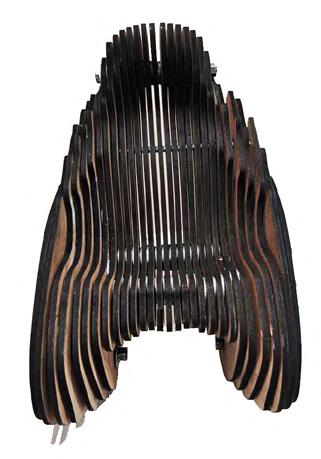
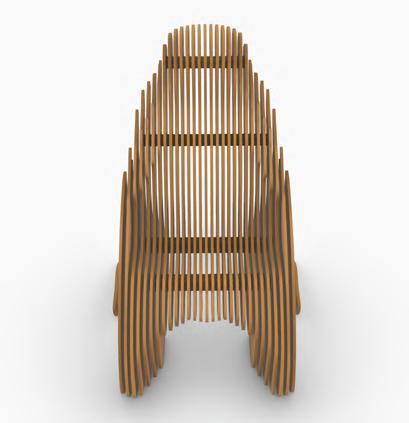
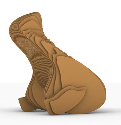

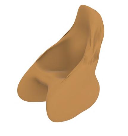
Laminated HDHMR Board. (High Density High Moisture Resistance. 12mm thick Standard sheet size 8’x4’
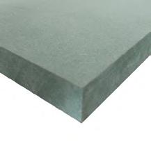
2” X 2” Cross Section Wooden Connector and 12mm pieces shall be used as spacers Duco paint : Spray painted
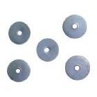
Assembled prototype at 1:5 scale
Assembled prototype showing the spaces between the pieces equal to its thickness
DIGITAL FABRICATION - ASTER - A Robotically Woven Pavilion

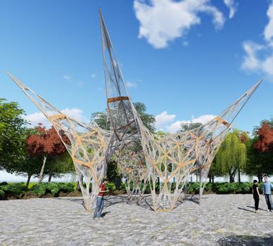
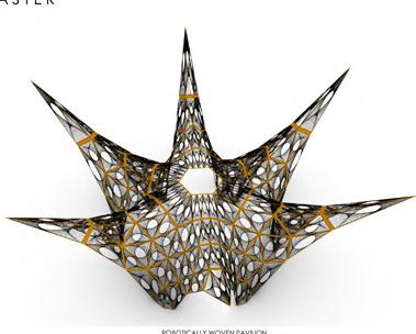
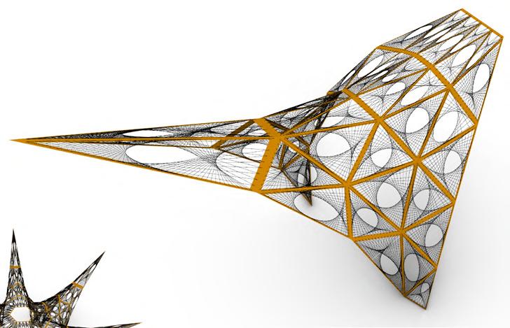
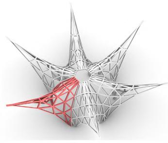

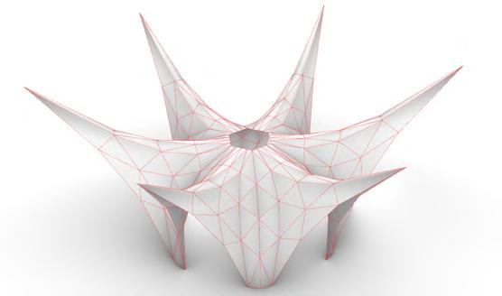
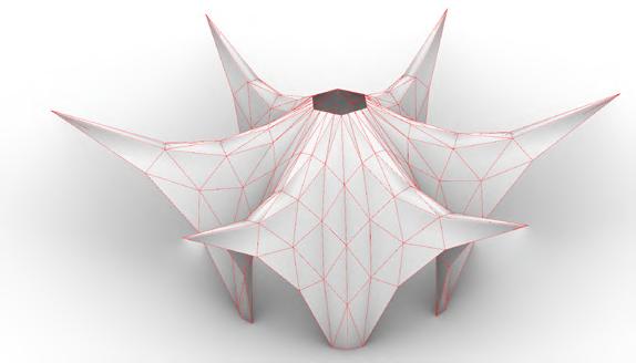
EXPERIMENT - 1 - With cloth as the main material
Draping Hanging
EXPERIMENT - 2 - Iterations
Gravity - Kangaroo Physics
In this form finding experiment, the mesh is considered as cloth & then it is hanged from various anchor points to derive the form of the structure.

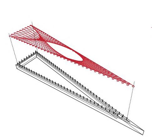
CONCLUSION
In this form finding experiment, the mesh is considered as cloth & then it is draped on objects to derive the form of the structure.
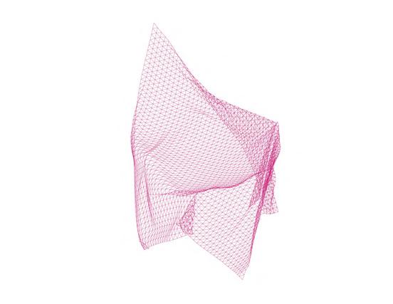
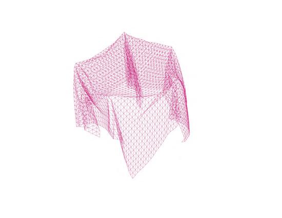
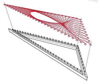
TRIANGULATED FRAMES - FINAL DESIGN

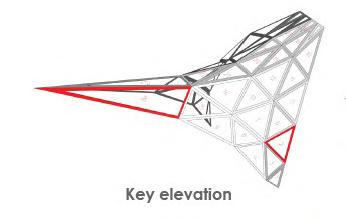
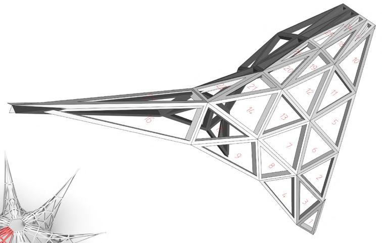
As the objective of this assignment is to design a lightweight woven pavilion, both of these experiments were not carried forward.
Iteration 1 - View
Base polygon radius - 3m

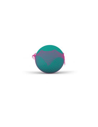
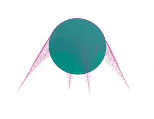
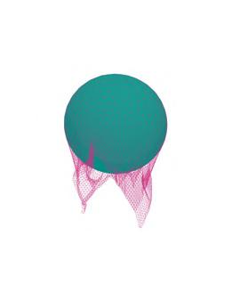
Sides - 12
Bottom anchor points - 6
Top edge anchor point - 6
Top edge anchor point offset - 4m
Top edge anchor point height - 7m
Central anchor points height - 7m
ROBOTIC WEAVING PATTERNS
Iteration 2 - View
Base polygon radius - 4m
Sides - 12
Bottom anchor points - 6
Top edge anchor point - 6
Top edge anchor point offset - 4.5m
Top edge anchor point height - 8m
Central anchor points height - 5m
Iteration 3 - View
Base polygon radius - 4m
Sides - 8
Bottom anchor points - 4
Top edge anchor point - 4
Top edge anchor point offset - 5m
Top edge anchor point height - 10m
Central anchor points height - 5m
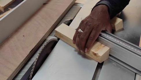
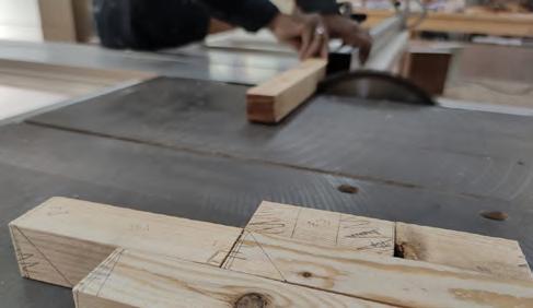
CARPENTRY WORKSHOPfabrication of frames
FABRICATION LAB - Robotic weaving
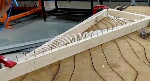
Partly weaved frame fixed to the table for weaving purpose
Fabricated Flange
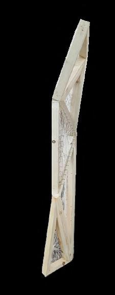
Total Frames - 48
Scale model of 1: 0.3
Frames - 1 to 21 & 24 - 2 each (Symmetrical on other side)
Fabricated Flange
Total Frames - 48
Scale model of 1: 0.3
Total Weaving thread length794 m
Pavilion View
Frames - 22, 23, 24 & 26 - single each Pavilion View
Manual fabrication of frames
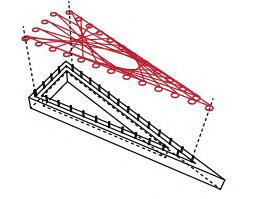
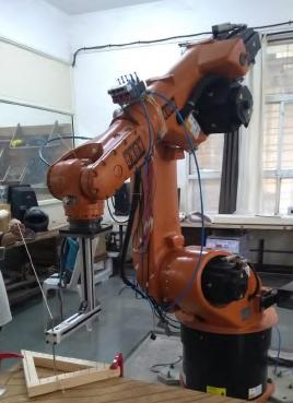
Robotic weaving in process with robotic arm & the weaving tool
Robotically weaved frames
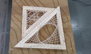
1.245 m X 1.19 m X 0.264 m
- Total number of nails - 81 (30mm c/c)
- Weaving Total Length - 47.932 m
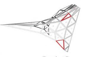
Key elevation Frame 19
Key elevation
- Sides - 0.948 m X 0.756 m X 0.328 m
- Total number of nails - 61 (30mm c/c)
- Weaving Total Length - 29.217 m
Frames with nailing done at 30mm c/c distance on the centerline of frames
Detail of Knotting around the nails - Each nail has 2 rounds of thread for knotting

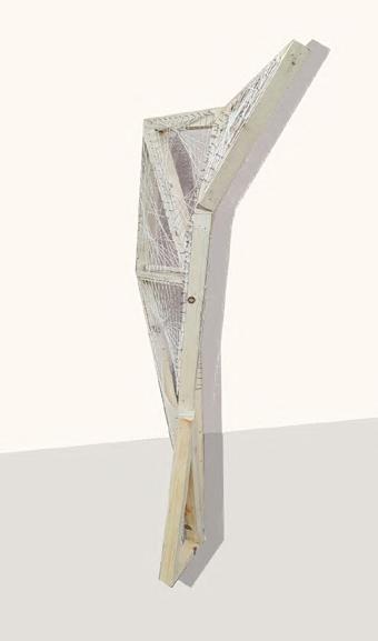
Part fabricated pavilion - 8 parts
Part pavilion model with 8 frames joined together using wedges
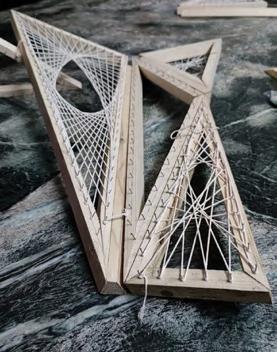
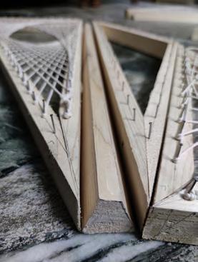
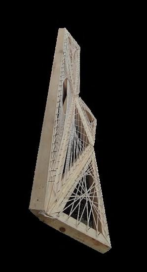

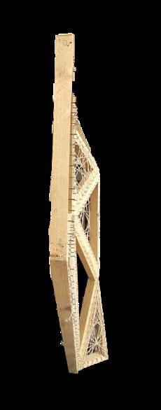

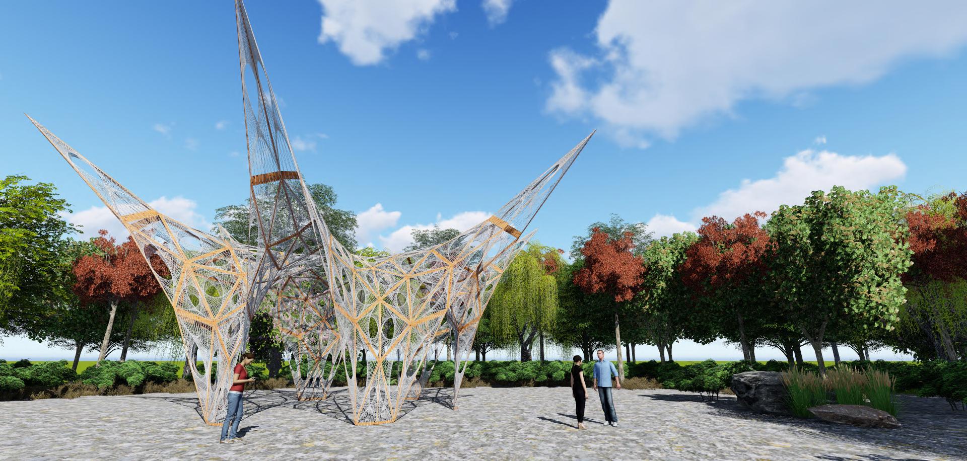
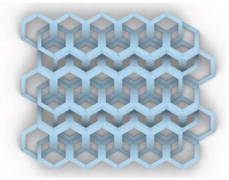
Hexagonal Grid to create the points of the undulated surface and create opening locations to create the weaved pattern
LEARNINGS & FUTURE SCOPE DESIGN
The overall pavilion form is designed as symmetric thus there were less challenges with the structural stability of the structure. Although the form is interesting, a little more exploration with asymmetrical forms could also have been done, where one could understand more about the structural stability of the form.
PANELIZATION & FABRICATION OF FRAMES
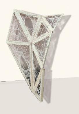
In the start, the penalization was explored with non-planner hexagonal frames. But due to fabrication challenges, like how to construct the non-planner hexagonal frames with exact precision & time limitations, later planner triangular frames were taken forward for fabrication. Thus, for future exploration, the non-planner frames can be explored & fabricated.
ROBOTIC WEAVING
For planner triangular frames weaving, the robotic weaving was quite easily resolved & the time taken for the actual weaving process was also less. For robotic weaving an observation was made that the precision in the drawings, like frame sizes & nails location is of almost importance, otherwise the weaving tool starts hitting the nails. The nail heights also need to be resolved so that the tool doesn’t get tangled in the weaved threads. For this attempt we explored one or two layers of weaving for each frame, in future more weaving layers or complex weaving patterns can be explored.
Also, for this assignment, the weaving was viewed as mostly covering or infill materials on the frames & it didn’t have any role in the structural stability or strength of the structure like it does in the case study of ICD pavilion. So, one can further work as to how the weaving can also be more of an integrated part of the pavilion in the future works.
In conclusions, there is a lot of future scope to take this project further & rework to resolve the identified problems & to work in the alternate directions mentioned above. The many lessons learned in this project can be very useful for various fabrication projects too, like the stepwise process that needs to be followed & most importantly time management.
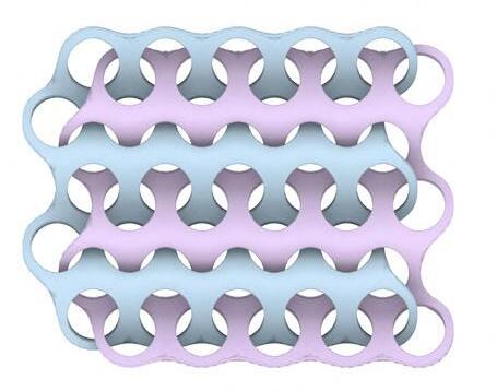
Lofted weaved surface Smoothened Mesh
Data for the weaving pattern: The angle between radial vectors from center point each hexagon cell towards the control points and X axis.
Honeycomb like structure formed at the base for support of the actual model

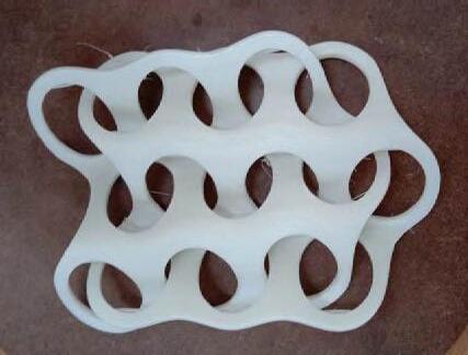
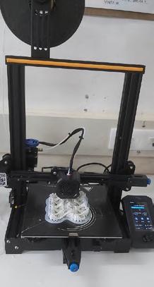
3D printing being done
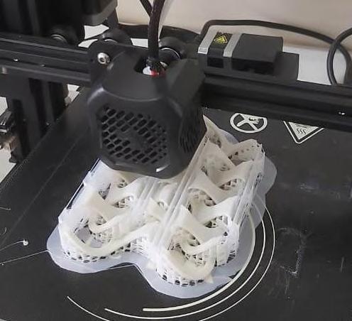
Dependign upon the angle, points are dispathced on the left and right side.
Final model
Size: 13.6 cm x 10 cm
Thickness: 2.5 mm
Printing time: 5 Hours
Final model after removing the supports
Textures
Finishing:
Before painting
1. surface to make oil-free, dust-free


2. To be painted in several thin coats
The model to be finished in Navy Blue Matte Acrylic Varnish
GUEST COTTAGE - Reciprocal Dome - Amjhira Farms
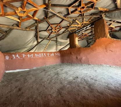
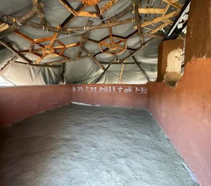
Amjhira Farms is a community nestled in the hilltop forest, surrounded by 2 villages in Sagar, M.P. India. It is an upcoming community with ecofriendly practices like organic farming, natural construction and many more. The project holders decided to build houses and communal spaces with the vernacular materials and practices with a touch of unique aesthetics.
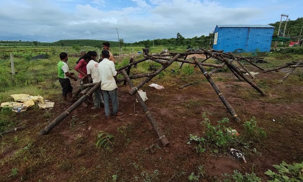
The very first experimental building being small Guest Cottage of area around 900 sq.ft. using the Earthbag Technique for the foundation and walls and the Reciprocal Frame for the Roof.
This structure is mainly planned as the first and the only shelter on the land of 70 Acres and we intend to train the local labors through this construction. Currently the building is under construction.

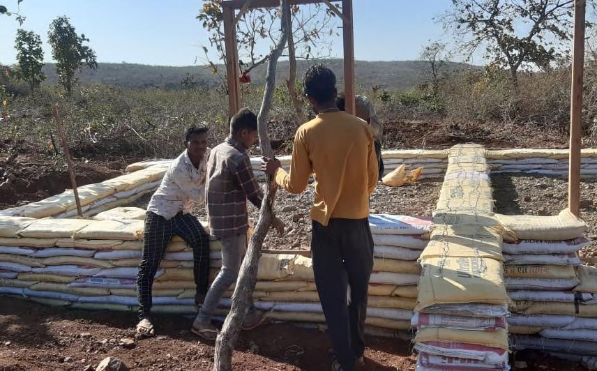
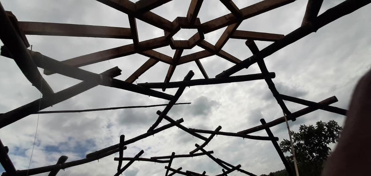
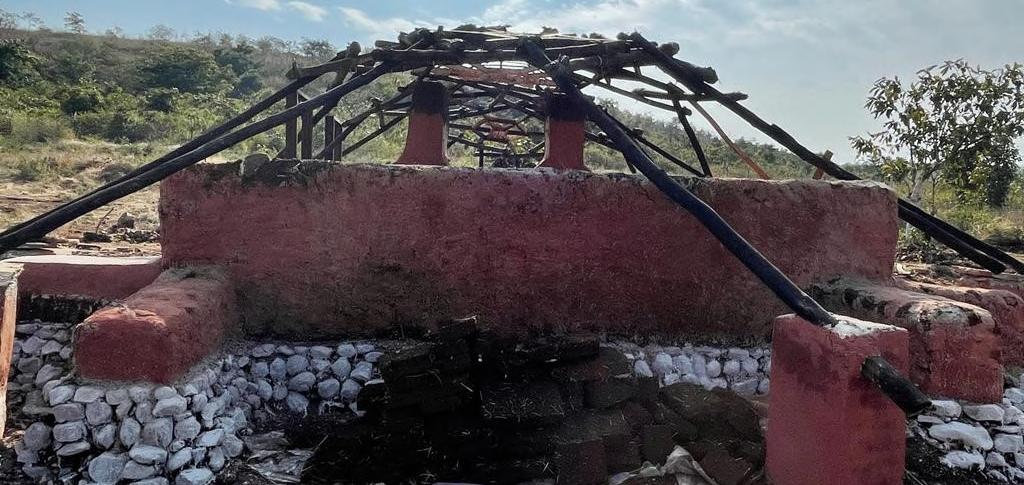
The structure is temporarily covered with canvas sheet to protect the walls from heavy wind and rains
The entire structure was planned on the site and executed immediately. The Reciprocal Frame Dome came in the plan after series of discussions with the project holders.

All the materials used except for the wood are harvested from the 70-acre land area. Locally available Eucalyptus ballis are used for the main structure.
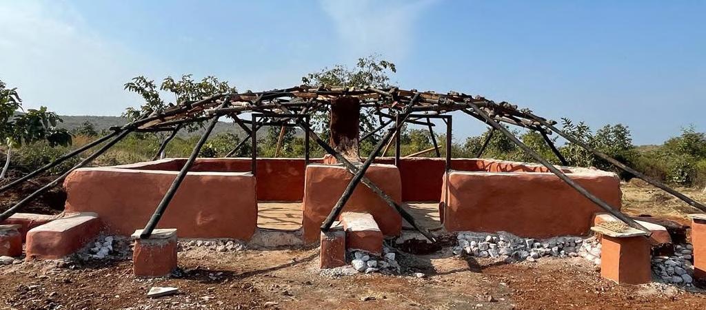
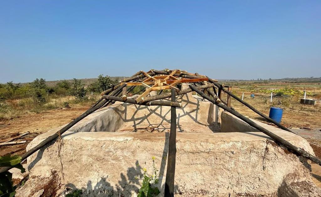
The roof will be later covered with the same canvas sheet after adding the cupola and elevated overhangs to achieve the necessary height at the corners.
FARM-HOUSE - Amjhira Farms
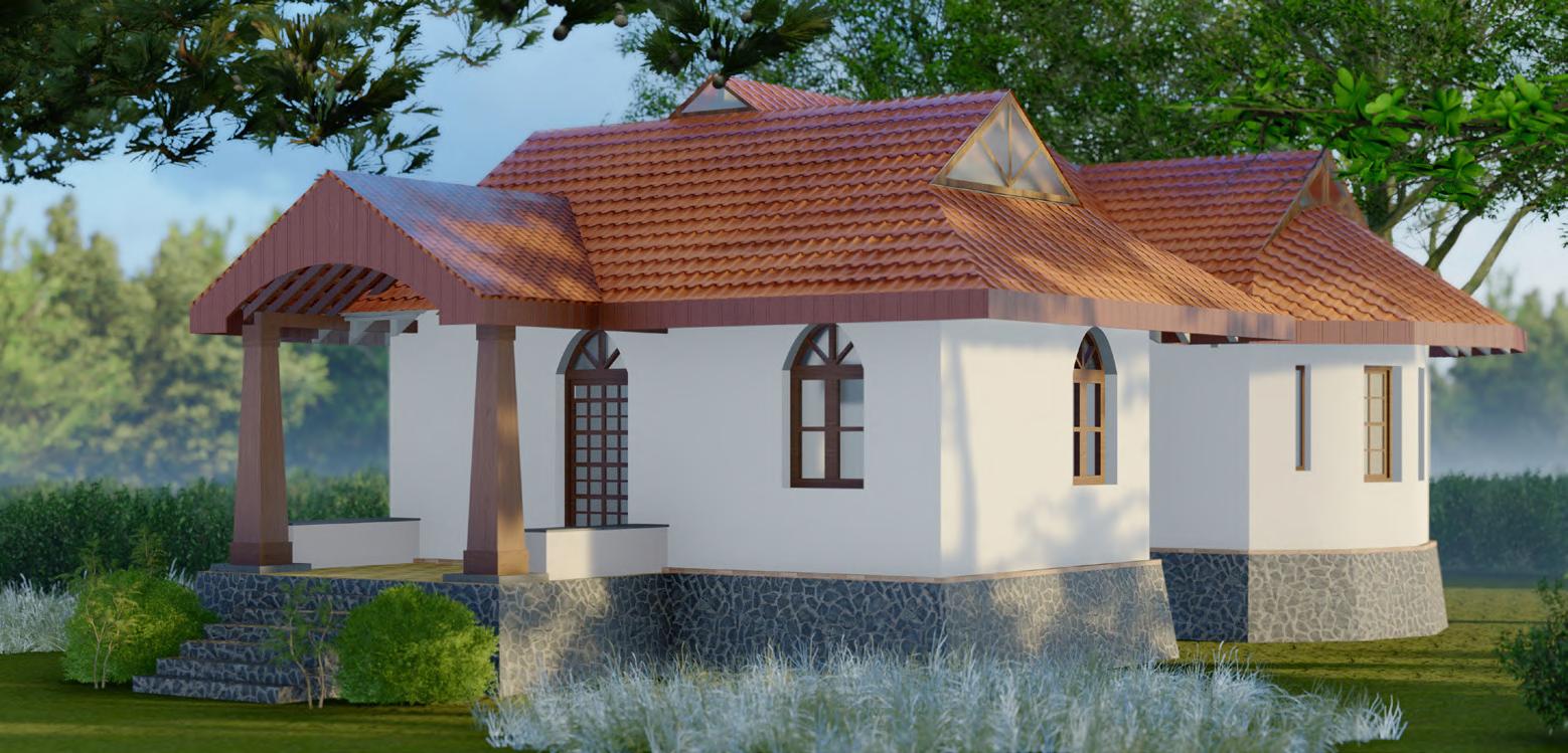
The Farmhouse is the second structure on the site of 70 acres with 15 acres of forest included in the site. Since the site is rich with natural resources, the entire house is designed with locally available materials and practiced techniques.
We also hired a water management team from renowned ‘Paani Foundation’ to tackle the current issues on site, like soil erosion and excessive water run off due to low contours in most of the site areas.

The Farmhouse is located at one acre of land, adjacent to the forest. Most of the major materials like stone and mud are harvested from the site itself. The use of Steel and cement is restricted to only plinth and roof beam level.
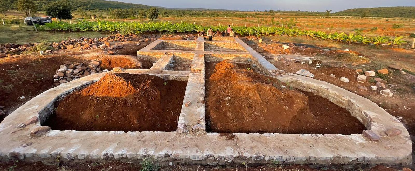
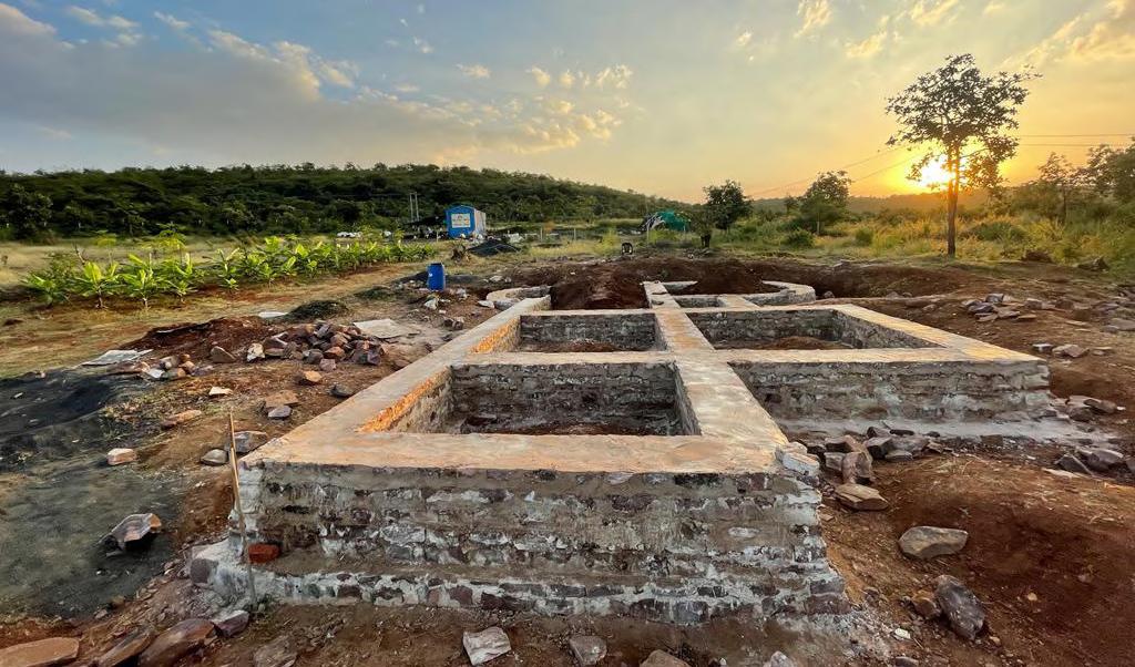
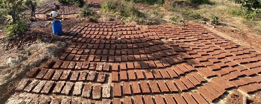
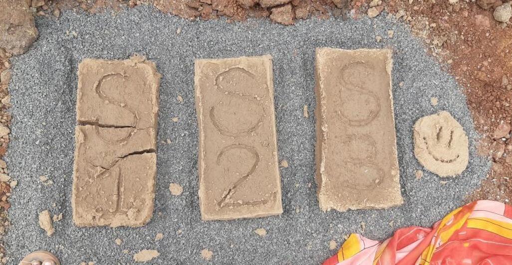
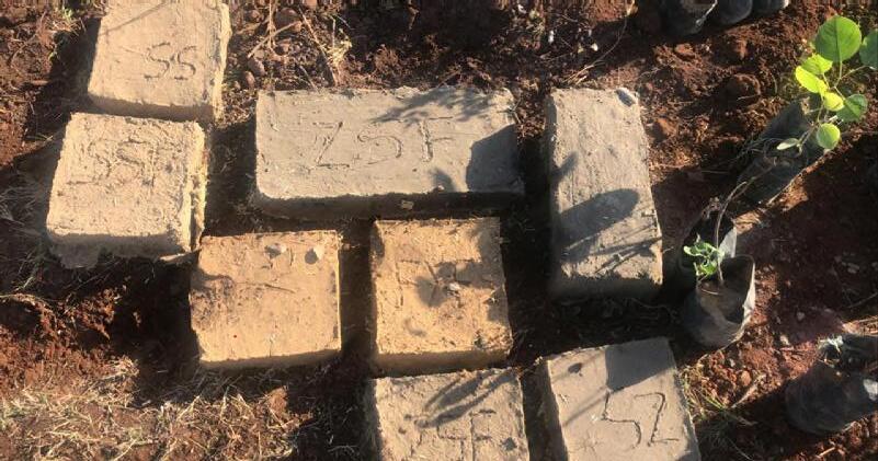
The local team of masons and helpers is being trained for the required skills. The Foundation and the plinth is constructed with the locally available stone and the walls to be built with the mud bricks are manufactured in-situ. Being a load bearing structure, the walls are 450 mm thick, hence the brick size was modified to 18”x9”x3”
Lime Preparation for mortar and plastering Other preparatory work set up
The cement mortar and plaster are replaced with traditionally prepared lime mortar. Except the limestone powder and sand, other additives were harvested from the site itself.
The pan mixer grinder needed to prepare the lime mixes was locally manufactured. The labors team was trained to handle exothermic lime and mortar preparation.
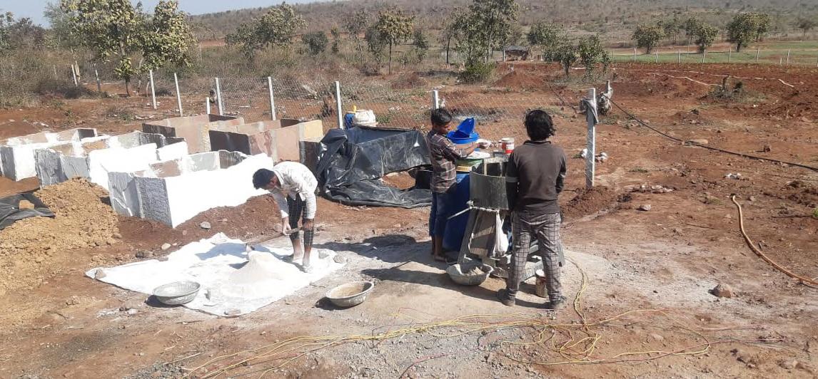
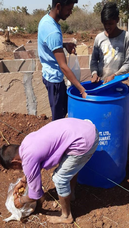
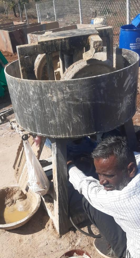
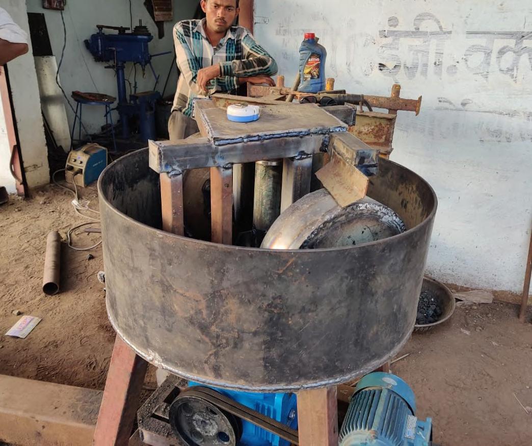
The roof beams and rafters shall be constructed with the teak wood and other members with the local wood, which will be covered by the locally available clay tiles.
The freshly made clay tiles are difficult to find in the surrounding villages as traditional tile maker have stopped the production due to the decreasing supply demands. Therefore, we decided to use the reclaimed clay tiles as roof covering.
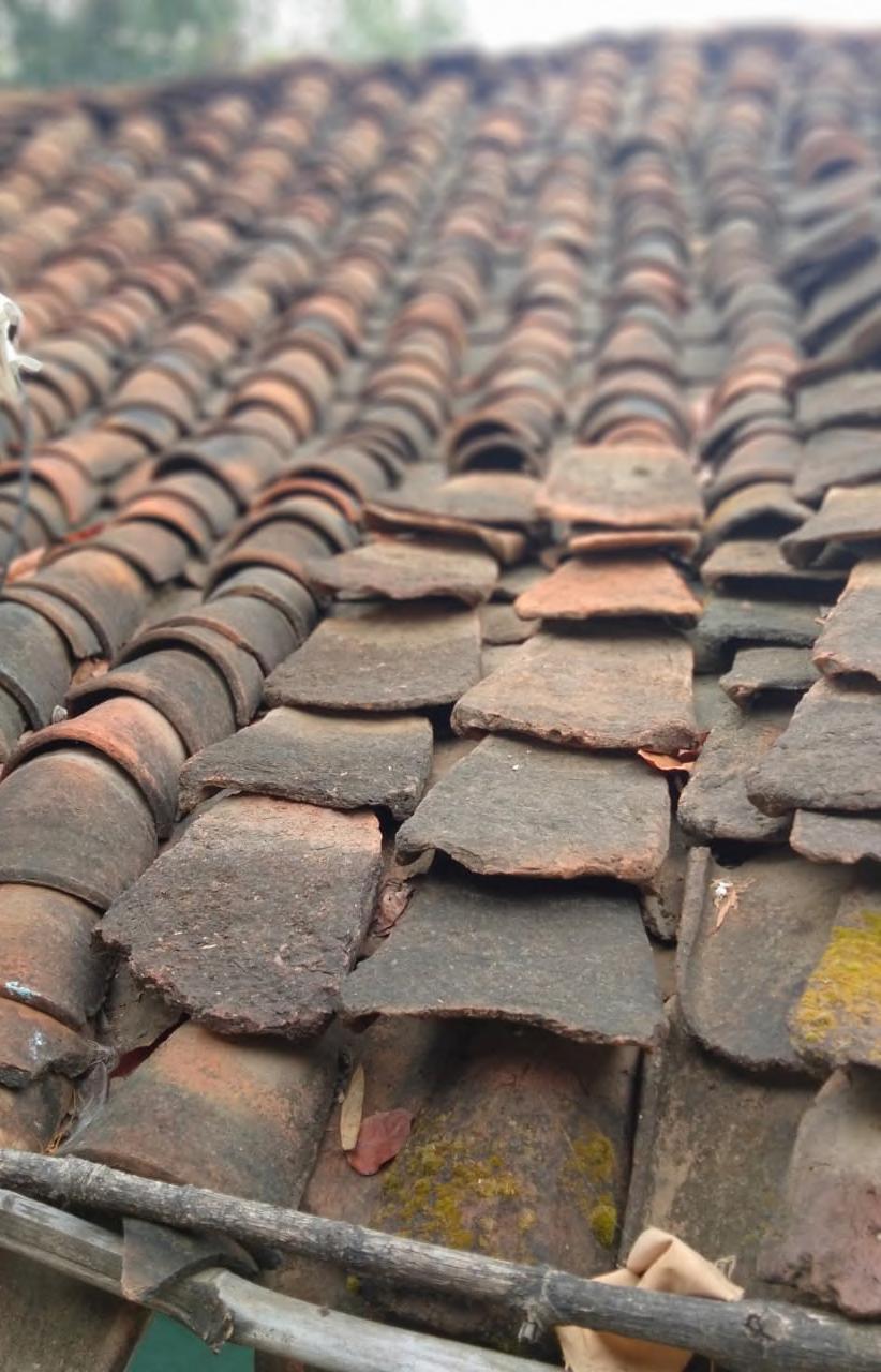
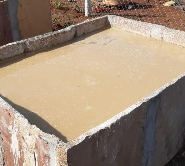
Tank filled with prepared Lime mortar for the stone masonry work for foundation and plinth.
Later, the plaster to be prepared with the same process and replaced with the mortar in the tank
The
The other additives were being prepared simultaneously. After the preparation, lime and sand was mixed in the dried form and the dry mix was added to the pan mixer along with the additives and fermented jaggery water.
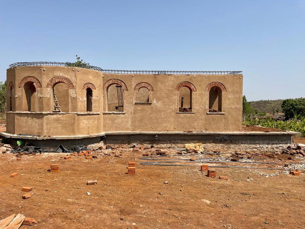
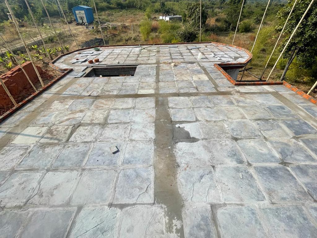
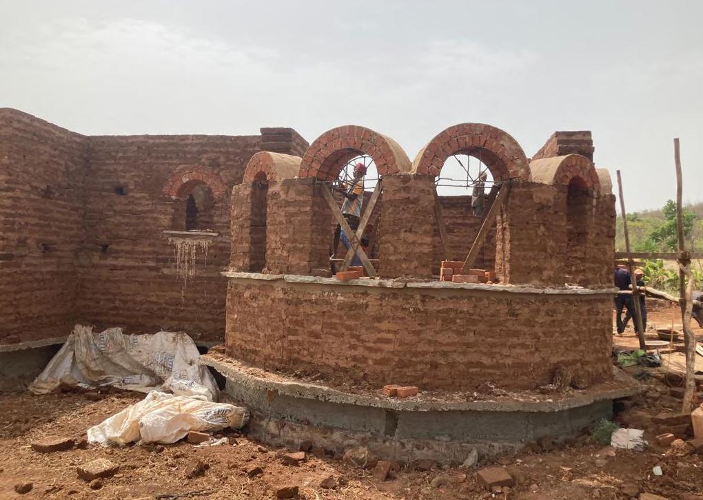
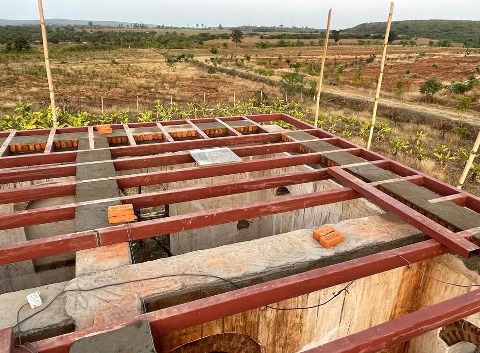 Walls an Arches construction
Kaddapa slab with lime concrete finish
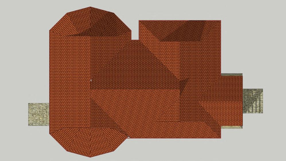
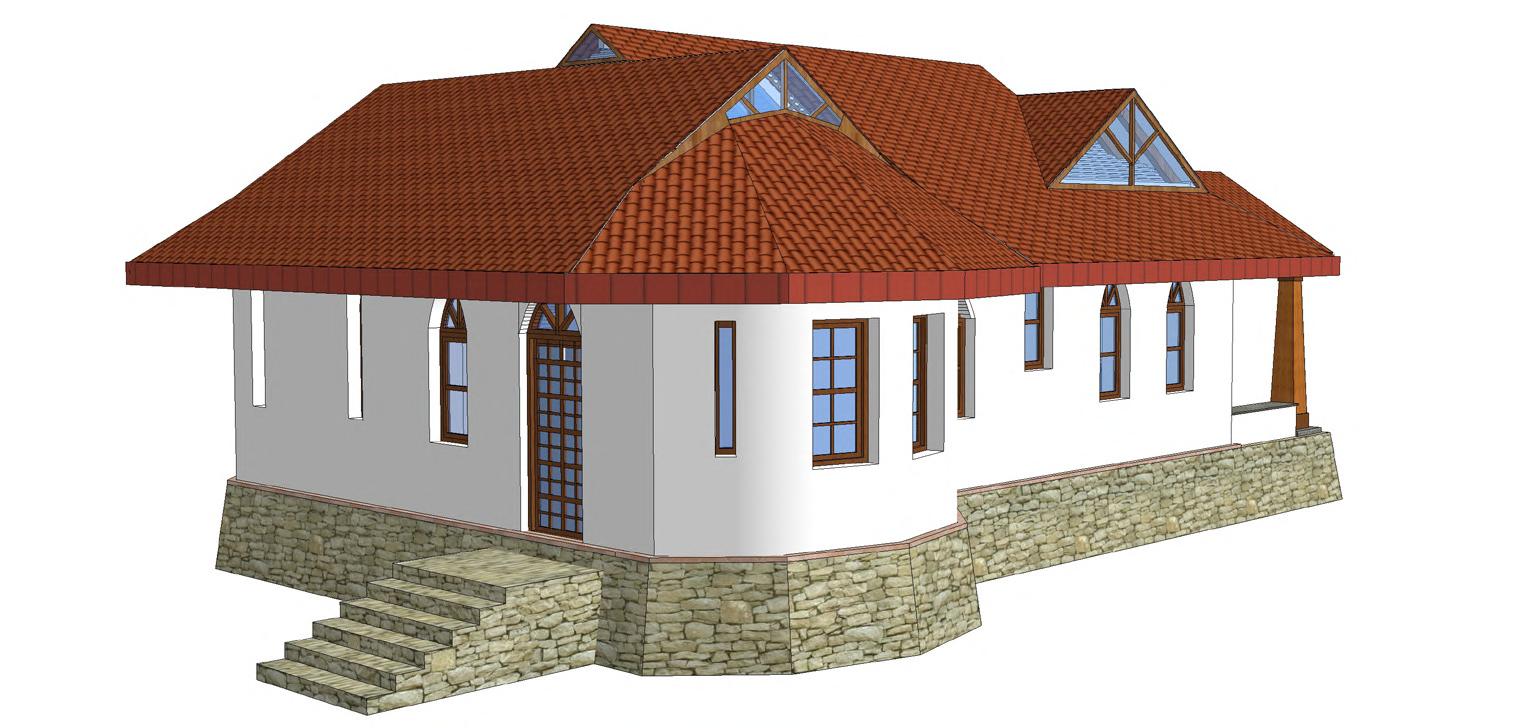
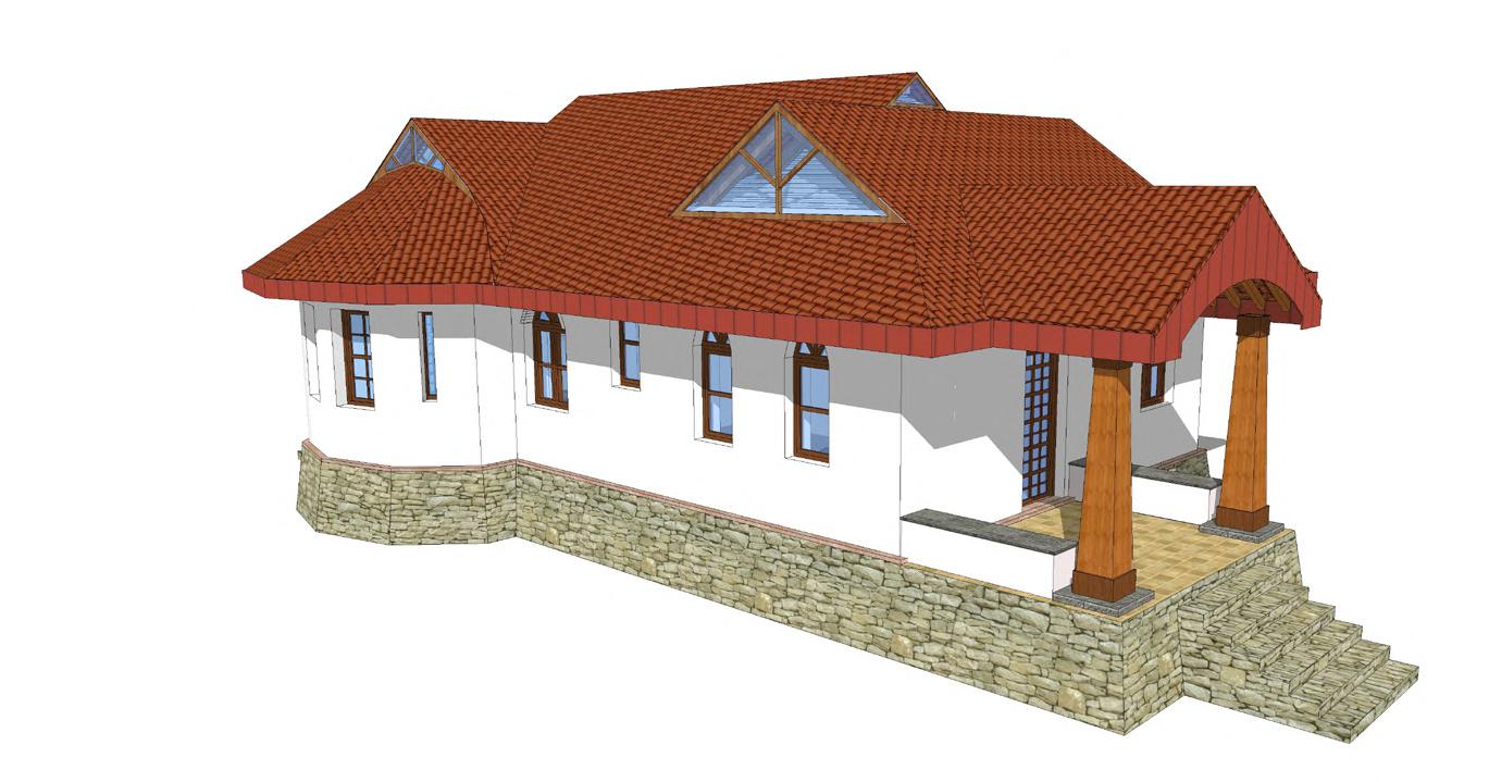
Farm House Drawings and Views (Original Design)



SACRED GROVES, AUROVILLE - Ecological Housing - Prototype Houses
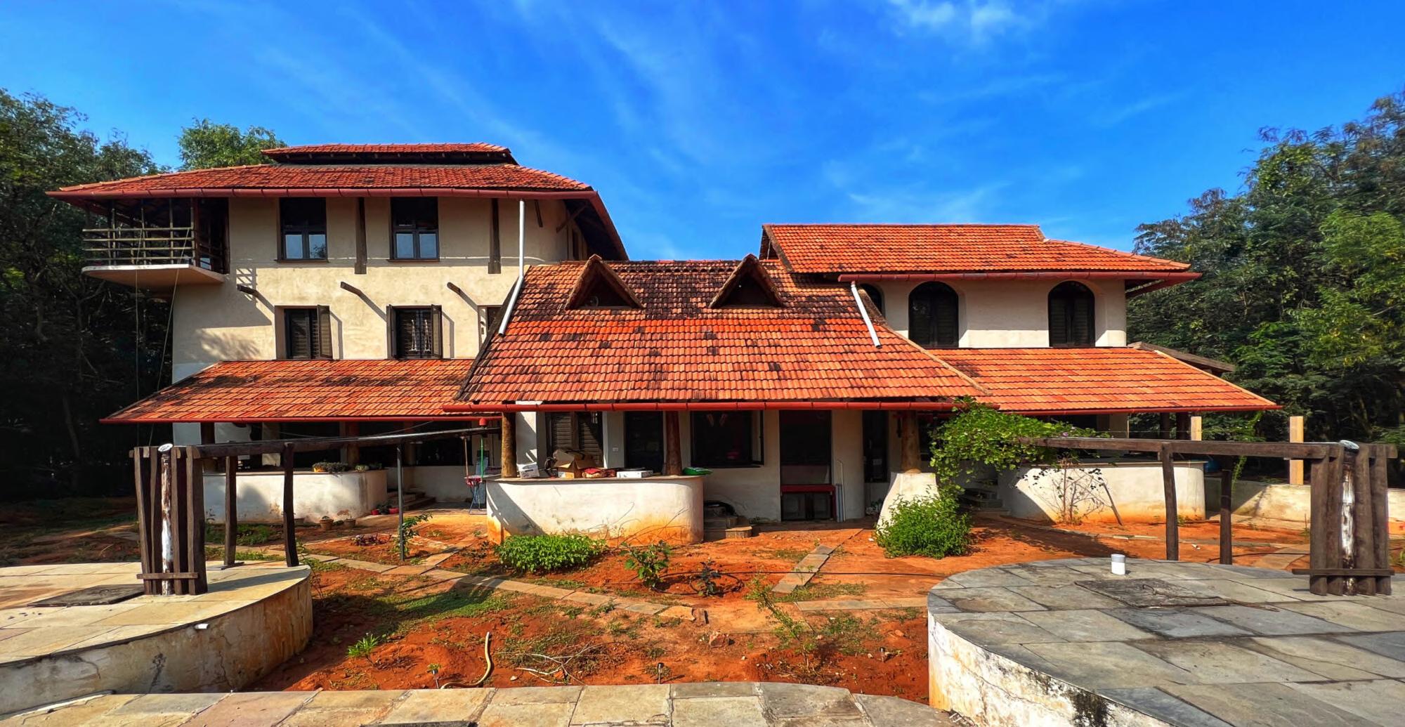
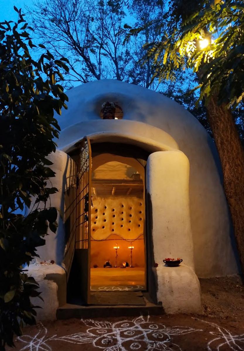
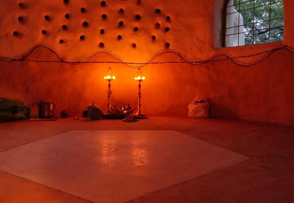
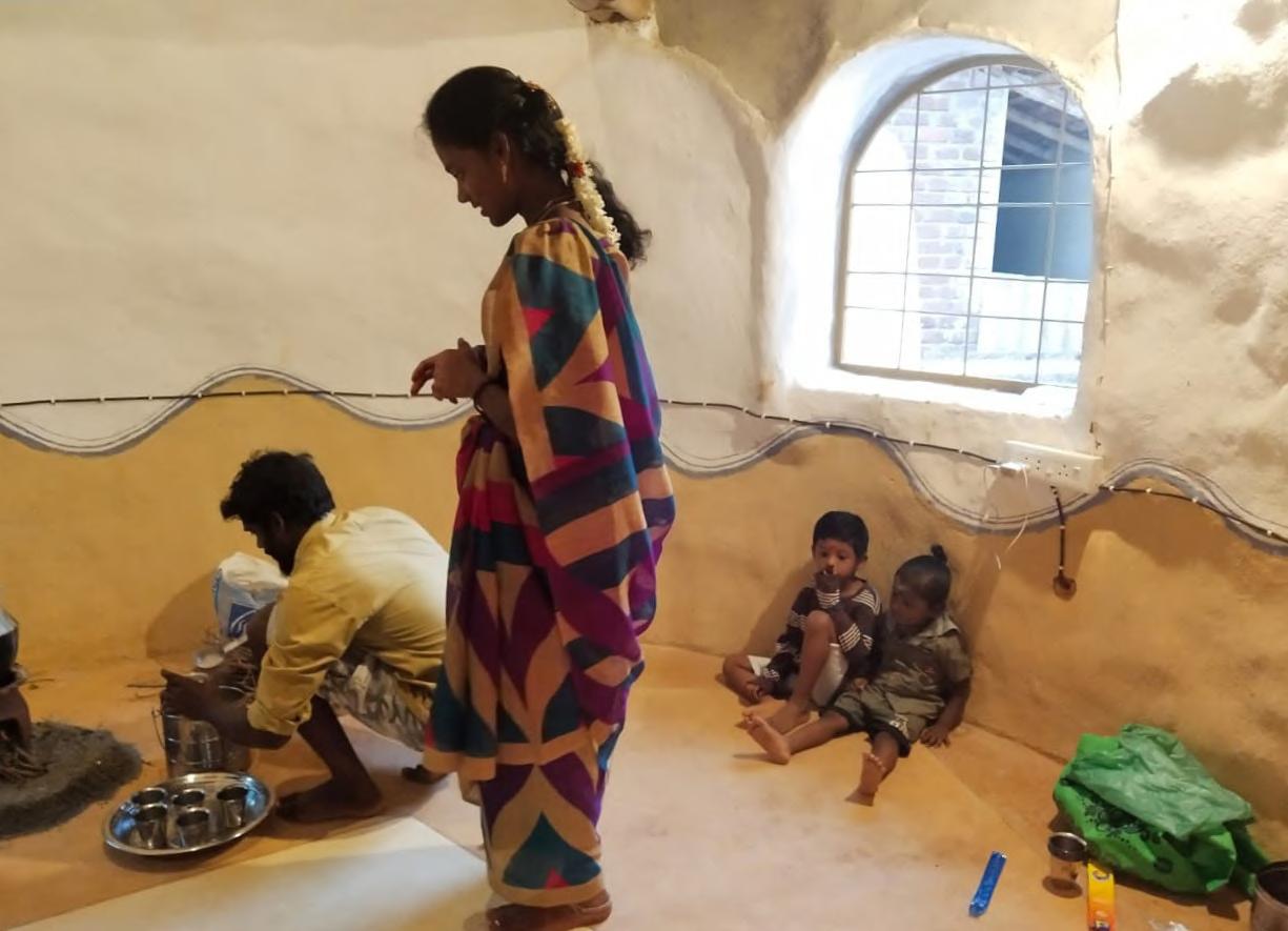
Sacred Groves in Auroville, India is an Ecological Housing Project envisions to build 108 Earth Houses for Aurovillians and newcomers. The first 3 prototype houses includes a single unit, couple unit and a family unit. The prototype was built with a major participation from the students and learners all around the world.
The construction techniques used to build these houses inherit from the traditional construction knowledge from the past. The principal Architect of the project along with the team of core team members, studied the vernacular construction techniques through conversations, documentations and experimentations. This knowledge is shared with the natural building enthusiasts through the volunteering and internship programs as well as site tours and workshops hosted by Sacred Groves Community.
The major techniques used to construct all the buildings at Sacred Groves are Cob, Adobe, Wattle and Daub, Earthbag, Limecrete and Earthcrete. The finishes techniques used are Lime plasters for exteriors, Mud Plasters for interiors and Araish Plasters for the wet areas.
Prototype Houses - Single unit - Interior

SACRED GROVES, AUROVILLE - Build Free - Volunteer House
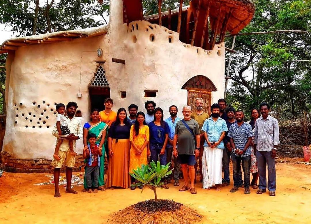
Volunteer House - Interior

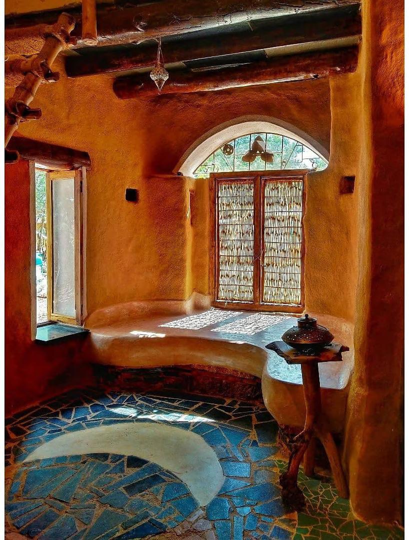
SACRED GROVES, AUROVILLE - Earthbag House
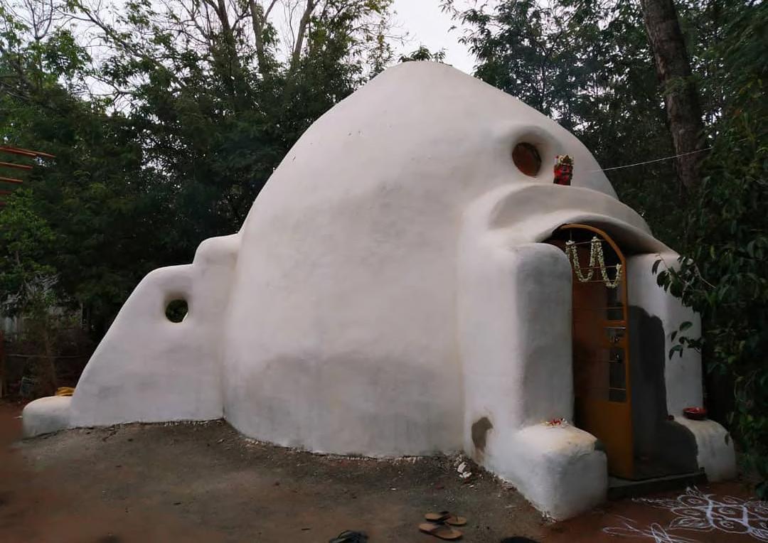
Earthbag House - Interior
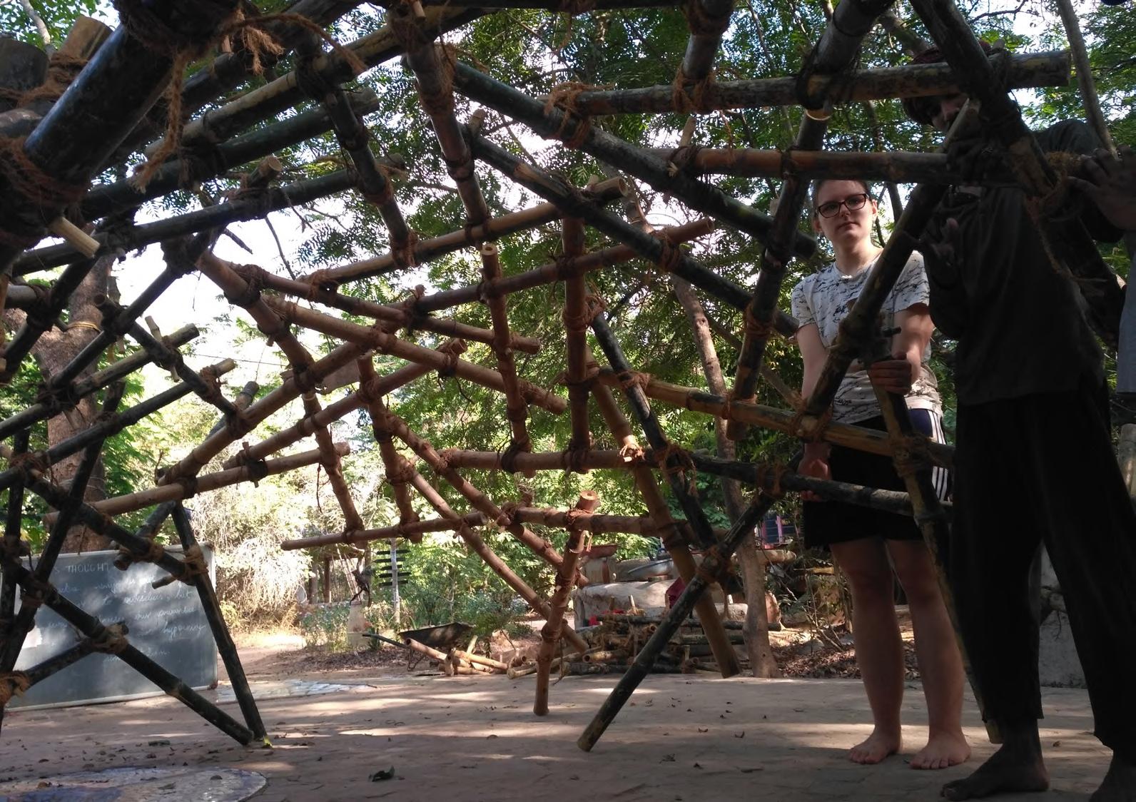
SACRED GROVES, AUROVILLE - Reciprocal Roof - Introduction to reciprocal frame structures

Reciprocal Roof
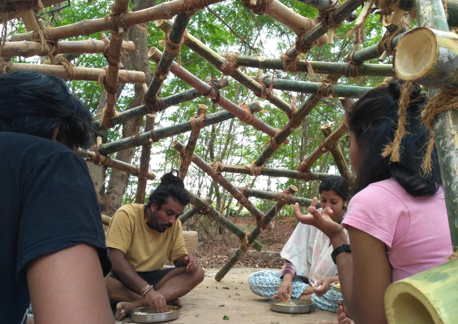

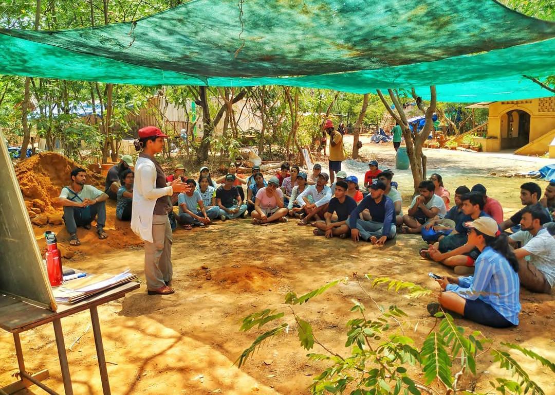
SACRED GROVES, AUROVILLE - Workshops
