No part of this publication may be reproduced or transmitted in any form or by any means, electronic or mechanical, including photocopying, recording, or any information storage and retrieval system, without permission in writing from the publisher. Details on how to seek permission, further information about the Publisher’s permissions policies and our arrangements with organizations such as the Copyright Clearance Center and the Copyright Licensing Agency, can be found at our website: www.elsevier.com/permissions
This book and the individual contributions contained in it are protected under copyright by the Publisher (other than as may be noted herein).
Notices
Knowledge and best practice in this field are constantly changing. As new research and experience broaden our understanding, changes in research methods, professional practices, or medical treatment may become necessary.
Practitioners and researchers must always rely on their own experience and knowledge in evaluating and using any information, methods, compounds, or experiments described herein. In using such information or methods they should be mindful of their own safety and the safety of others, including parties for whom they have a professional responsibility.
With respect to any drug or pharmaceutical products identified, readers are advised to check the most current information provided (i) on procedures featured or (ii) by the manufacturer of each product to be administered, to verify the recommended dose or formula, the method and duration of administration, and contraindications. It is the responsibility of practitioners, relying on their own experience and knowledge of their patients, to make diagnoses, to determine dosages and the best treatment for each individual patient, and to take all appropriate safety precautions.
To the fullest extent of the law, neither the Publisher nor the authors, contributors, or editors assume any liability for any injury and/or damage to persons or property as a matter of products liability, negligence or otherwise, or from any use or operation of any methods, products, instructions, or ideas contained in the material herein.
Previous editions copyrighted 2002, 1992, 1982 by Churchill Livingstone.
Library of Congress Cataloging-in-Publication Data
Rogers, Lee F., 1934- , author.
Imaging skeletal trauma / Lee F. Rogers, O. Clark West. -- Fourth edition. p. ; cm.
Preceded by Radiology of skeletal trauma / [edited by] Lee F. Rogers. 3rd ed. c2002.
Includes bibliographical references and index.
ISBN 978-1-4377-2779-1 (hardback : alk. paper)
I. West, O. Clark, author. II. Radiology of skeletal trauma. Preceded by (work): III. Title.
[DNLM: 1. Bone and Bones--injuries. 2. Fractures, Bone--radiography. WE 175] RD101
617.4’71044--dc23
Executive Content Strategist: Helene Caprari
Content Development Manager: Gabriela Benner
Publishing Services Manager: Anne Altepeter
Project Manager: Jennifer Nemec Moore
Design Direction: Teresa McBryan Printed in the United States of America
Last digit is the print number: 9 8 7 6 5 4 3 2 1
2014037963
To my father, the late Doctor Watson F. Rogers, of Vienna, West Virginia, a true physician; loved by his family, admired by his patients, and respected by his colleagues. Born in St. Albans, Vermont, raised in Vergennes, Vermont, and educated at the University of Vermont, he practiced medicine in Underhill, Vermont, and Vienna and Parkersburg, West Virginia.
And the memory of our medical heritage, all physicians, all Vermonters: my grandfather, Doctor Frank Matthew Rogers of St. Albans and Vergennes, Vermont; my great uncle, Doctor Daniel Lee Rogers of Bolton Landing, New York; my great uncle, Doctor Sam Rogers of Proctor, Vermont; my uncle, Doctor Samuel Rogers of Stowe, Vermont; and to all those who may have suffered as we learned.
And to my grandchildren, Dean, Garrison, Megan, Westin, John, and Morgan, in the fond hope that whatever they may become and wherever that might be, they too find something as rewarding and meaningful to do with their lives as those of us who have preceded them.
And last, to my wife, Donna B., who made this and all other of my works possible. I am most grateful for her forbearance and tolerance of my preoccupations through the four editions of this book. It is hard to imagine having completed these works without her constant love, encouragement, and support.
Lee F. Rogers
To my recently deceased uncle, Emory Guth West, MD, FACR, born in Des Moines, Iowa, and educated in Medicine and Radiology at Northwestern University in Chicago. He practiced Radiology in Mountainview, California. In my “tween” years, spending days watching him work in his office and conversing with him about “automotive medicine” – the precursor of modern trauma care – provided the spark for my career.
To my father, George Guth West, MBA, JD, born in Des Moines, Iowa, and currently resident of Henderson, Nevada. His support throughout my medical training and his encouragement to pursue a career in an unorthodox field – academic trauma imaging – have been invaluable.
To my wife, Victoria Kiechler West, and daughter, Rebecca Kathryn West, for their unwavering love and support in all my professional endeavors.
And to all radiologists who think of themselves as Emergency Radiologists or Trauma Radiologists. This book is for you – to provide the knowledge base for excellence in imaging skeletal trauma.
O. Clark West
Preface
It has been 12 years since the previous edition of this work. A lot has happened in the interim. Microprocessors have revolutionized imaging; not only the means of medical imaging but how images are viewed and reported; how these reports are recorded, transmitted, and communicated; how images are stored and retrieved; and even how one seeks information regarding the imaging characteristics of disease or searches the literature to learn of or substantiate their findings. Microprocessors have made images, reports, and the clinical, pathologic, and imaging characteristics of disease instantaneously accessible. We have achieved the potential of “real-time radiology.”
As a result of microprocessor-driven innovations in information accessibility, the nature of textbooks has changed. Because of the online availability of medical images and accurate and reliable information, the demand for and need of larger general texts has diminished while readers’ requests for shorter, portable single-topic works that might be downloaded on desktop computers, laptops, iPads, and smart phones has risen. Our work has been revised in its fourth edition to accommodate readers’ requests.
But we did not start out that way. In planning for the fourth edition of my text I was fortunate to secure the assistance of Professor O. Clark West of the University of Texas Health Science Center at Houston Medical School, an internationally recognized authority in the field of Emergency Radiology, as a partner and fellow author in this endeavor. Dr. West heads the Emergency Radiology Section of the Department of Diagnostic and Interventional Imaging, which services the active Level 1 Trauma Center of Memorial Hermann Hospital in Houston’s sprawling Texas Medical Center and has a particular interest and extensive clinical experience in the application of multidetector CT (MDCT) to trauma imaging. In view of his interest and expertise Dr. West accepted responsibility for authorship of the chapters devoted to the axial skeleton: cervical spine, thoracolumbar spine, and pelvis, and I authored eight chapters devoted to the peripheral skeleton: shoulder, elbow, wrist, hand, hip, knee, ankle, and foot.
The previous three editions of Radiology of Skeletal Trauma were two-volume texts of 1400 to 1700 pages. In preparing a manuscript for a fourth edition the publisher asked that we provide a single-volume text of approximately 300 pages. This substantial reduction presented a significant challenge. Dr. West and I hesitantly agreed to undertake the task. We gave it our all, but found the results of the required shortening produced chapters far short of our goal to provide a useful, informative, and instructional resource. The product of our labors was simply unacceptable.
However, all was not lost. While working on the revision, I became increasingly aware of the troubling thought that I had written three two-volume editions of a book containing considerable information but had never informed the reader precisely how I used this information in the assessment and interpretation of images of skeletal trauma. To this end we had decided to add what I called a “primer” at the beginning of each chapter containing the basic information needed to make an informed judgment and confident interpretation of images of skeletal trauma. We then stopped working on the revision and turned our attention to writing a primer for each anatomic area. It took three to four years to complete this undertaking. Ultimately, we came to the conclusion that the primers alone had the making of a good short text and abandoned our attempt to make a standard revision of the previous edition.
We define a primer as a small exploratory book on a subject – a collection of short informative pieces of writing that cover the basic elements. Our intent is that the information provided in this primer should enable users to confidently and accurately identify as many as 90% to 95% of fractures and dislocations that they encounter.
The Primer begins with checklists for each of the following:
5. Avoiding satisfaction of search: Now that you have seen this what else should you be looking for
6. What you do when you see nothing at all: Indications for CT and MRI
The checklists are followed by “The Primer,” a brief description with illustrative images for each separate checklist.
I personally designed the layout for the Primer in a Word document. Then I typed the manuscript, made the drawings, and downloaded the images into each primer. I used tif images in the primer documents, the same high-quality images that would be sent to the publisher for publication. This was done to show the publisher precisely how I wanted the manuscript laid out.
One day I was reading out with a resident, Dr. Ravi Shastri, now a Fellow in Neuroradiology at the University of Michigan. Ravi had seen printouts of a few of the chapters. He asked if he could download one of the primer Word documents on his iPad to show me what it would look like. I was curious. “Why not?” We copied one of the documents on his thumb drive and soon thereafter he showed me the primer document on his iPad. I was amazed. The images were dazzling. The ability to enlarge the images on the iPad was spectacular. Dr. Shastri’s demonstration on the iPad convinced me of the advantages and added value of the digital electronic presentation. I then showed the primers on my iPad to many radiologists—residents, fellows, and experienced practitioners—and all were impressed and found this format potentially useful.
Subsequently, I met with Don Scholz and Jacob Hart of Elsevier to show them several primer chapters on an iPad. They were also impressed. Ultimately Elsevier decided that the fourth edition of the text, now named Imaging of Skeletal Trauma would be published and available in both print and electronic forms. We are pleased by Elsevier’s decision to proceed in this fashion and grateful for their support.
Each chapter describes what I refer to as a “directed search” in viewing and interpreting radiographs of musculoskeletal trauma. Know specifically what you are looking for and look for it. Know what images to obtain, what injuries are likely and what they look like, what injuries are likely to be missed and why, how to avoid satisfaction of search—where else to look when you find certain injuries, and when to obtain CT and MRI.
This work would be of value to physicians in Emergency Medicine and Orthopedics as well as Diagnostic Radiologists. As written it is suitable for self-instruction or self-evaluation as well as an everyday go-to aid in the throes of reading images of musculoskeletal trauma from emergency rooms and elsewhere during the regular workday or when on call at night or weekends. This work could also form the basis of an introductory instructional course for beginners as well as a refresher course for the more experienced.
Dr. West and I could not have completed this work without the assistance of many others. My particular thanks to Michele Dalmenday for her attention to detail and exceptional secretarial support and to Duane Cookman for his assistance in acquiring the numerous images that were required from the files of the Department of Medical Imaging at the University of Arizona Medical Center in Tucson. The vast majority of the images are new; less than 10% were repeated from the third edition.
Dr. West’s principle coauthors were Susanna C. Spence for the spine chapters and Suresh K. Cheekatla for the pelvis chapter. His colleagues Naga Ramesh Chinapuvvula and Nicholas M. Beckmann contributed case material and their ideas.
The noun “primer” is recognized by many as a small book used to teach children to read such as the McGuffey Readers, so popular in elementary schools in the latter nineteenth and early twentieth centuries. McGuffey’s Readers may have been small but they produced essentially universal literacy among the American populace, no small achievement. Dr. West and I can only hope that we should be so fortunate as to achieve similar results with this primer, the elimination of “illiteracy” among those who interpret images of skeletal trauma and a noticeable improvement and greater confidence in the performance and interpretation of imaging examinations in skeletal trauma.
Read, mark, and inwardly digest. Dr. West and I are pleased to be of service.
Lee F. Rogers, MD Tucson, Arizona June 8, 2014
The primary objective in interpreting radiographs of skeletal trauma is to identify any and all skeletal injuries. However, despite the essentially universal availability and liberal use of radiographs, failure to diagnose fractures is a leading source of oversights in emergency departments and urgent care centers. Failure to recognize fractures on radiographs accounts for a significant percentage of diagnostic errors in these settings.
The interpretation of images obtained for the assessment of skeletal trauma is not intuitively obvious. Not surprisingly, experts in image interpretation recognize abnormalities more rapidly and with greater diagnostic accuracy than the novice with less knowledge and experience. An efficient and accurate approach is required and must be learned through study and practice.
Learn to do what the experts do. The expert search of images is not random. They know what they are looking for and what it should look like and where to find it. They seek out soft tissue signs that are known to point to underlying bony injury. They know the common sites of injury and look there. Experts are aware of the subtleties, know what they are likely to miss, and are mindful of the need to avoid satisfaction of search.
What are the characteristics of an efficient and effective approach to the interpretation of images of skeletal trauma?
First, obtain the proper radiographs. Insist upon proper radiographs. Standard views have been established for each anatomic part to ensure accurate assessment of potential injuries. High-quality and properly positioned images in these standard projections must be obtained to lessen the chance of errors and oversights. One view is no view. Fractures and dislocations cannot be excluded on one view alone. A minimum of two views is required to safely exclude fractures of the shaft of long bones. A minimum of three views — AP, lateral, and oblique — is required to safely exclude fractures of the ends of bone and dislocations of joints in the peripheral skeleton. Oblique views are essential. If the examination centered on joints is limited to just the AP and lateral views, 7% to 9% of fractures may be overlooked.
Second, be familiar with the sites and appearance of the common fractures and injuries. Look specifically at these sites for evidence of injury. Staring at a radiograph or other form of image in hopes you will note an abnormality is usually unproductive. In trauma the sites of injury are predictable and repetitive. Use what I term a “directed search”; develop a pattern of search to look specifically at the common sites of injury.
Third, know where to look for soft tissue signs that point to underlying bony injury. The presence of joint fluid, a visible joint effusion, in the setting of trauma is almost always a sure
CHAPTER 1 Introduction
sign of intraarticular fracture or ligamentous injury. This is particularly true of the knee and elbow and, to a lesser extent, the ankle and glenohumeral joint. Unfortunately, joint effusions in other joints are difficult to identify on radiographs. Periarticular soft tissue swelling is nonspecific but does direct your attention to the underlying bone, particularly in the ankles, fingers, and toes, but is more difficult to identify in the more proximal joints. Conversely, the absence of soft tissue swelling reduces, but does not rule out, the possibility of underlying injury.
Fourth, have knowledge of those subtle injuries that have a tendency to be overlooked or missed. Look deliberately for evidence of such injuries. A passing glance at such sites is insufficient. Most often overlooked fractures are fine, incomplete, or nondisplaced fractures at common sites, such as the femoral neck, carpal scaphoid, distal radius, or lateral malleolus, that would be readily apparent if more pronounced. Or they are fractures at less common sites of injury, blind spots, where the observer simply fails to search and observe, such as the bases of the fourth or fifth metacarpals with or without dislocations of the associated carpohamate joints.
Fifth, remain alert to the ever-present danger of satisfaction of search. Certain injuries tend to be associated with a second less-obvious injury. Having identified the first, the observer is satisfied and fails to seek the second. For example, fractures of the metatarsals and metacarpals are often multiple. Once you identify a metacarpal or metatarsal fracture, look closely at the adjacent bones for a similar though often less-obvious fracture. After identifying a fracture of the lateral or medial malleolus, look closely at the opposite malleolus and then the posterior malleolus for additional fractures.
In most cases, as above, the additional fracture is to be found on the same radiographic examination as the first. No additional images are required. However, this is not always the case.
In certain situations a second, additional examination is required. For instance, in a Maisonneuve fracture, a fracture of the ankle is associated with a fracture of the proximal fibula. The presenting injury of the ankle is commonly either a widening of the syndesmosis or an isolated fracture of the posterior malleolus, whereas the distal fibula and lateral malleolus characteristically remain intact. In this setting, having seen no fracture of the lateral malleolus or distal fibula, additional radiographs of the proximal tibia and fibula are required to disclose the accompanying fracture of the proximal shaft or neck of the fibula, the hallmark of a Maisonneuve fracture. Be aware of these associations and, having identified the first, obtain the appropriate additional radiographs, and look for the oft-associated second injury.
The ImagIng and deTecTIon of SkeleTal Trauma
This work consists of an introduction and 11 chapters centered on the primary components of the peripheral skeleton (shoulder, elbow, wrist, hand, hip, knee, ankle, and foot) and axial skeleton (cervical spine, thoracolumbar spine, and pelvis). Each chapter consists of two parts: the first, the Checklists, a series of checklists, and the second, the Primer, a short explanatory text based on the checklists.
Checklists
Checklists were devised to promote a disciplined approach to the interpretation of images obtained to assess skeletal trauma. The Checklists contain the most important characteristics and considerations employed in the interpretation of imaging in this setting.
Why checklists? According to Wikipedia, “a checklist is a type of informational job aid used to reduce failure by compensating for potential limits of human memory and attention. It helps ensure consistency and completeness in carrying out a task.”
Checklists were first devised for use in aviation initially to prevent pilot errors and subsequently as a means of addressing critical in-flight emergencies. These checklists have proven highly effective and are now the backbone of air safety.
I first heard of aviation checklists from Dr. David Levin, a renowned academician and interventional radiologist, who, prior to radiology, was an F-86 Sabre jet fighter pilot, during the Cold War with our then Russian adversaries. As a pilot he found checklists of great value and subsequently came to realize they would be helpful in medicine as well. Dr. Levin was particularly a champion of the use of checklists as an aid in the performance of interventional procedures.
The use of checklists in surgery has recently been publicized in a January 2009 article in the New England Journal of Surgery (1) and in a more recent book The Checklist Manifesto (2) by Dr. Utal Gawande, a Harvard surgeon. These reports attribute to the use of checklists both a significant reduction in surgical errors as well as an improvement in patient outcomes due to a reduction in postoperative complications.
In my view, checklists are a listing of summary statements compiled to direct the steps in the performance of a specific task. Checklists can be simple, straightforward, and are readily comprehended. Checklists can be quickly reviewed before, during, or after the performance of a specific task.
I believe, as does Dr. Levin, that there is a role for checklists in radiology, in this case, a role in the reduction of errors and oversights in the performance and interpretation of all forms of imaging obtained for the assessment of skeletal trauma.
A separate set of checklists is included for each chapter centered on the major joints in the peripheral skeleton and the individual sections of the axial skeleton. Separate checklists are required for each chapter to properly address the unique imaging features of the anatomy and traumatic injuries encountered in that anatomic area. These checklists can
serve as an immediately available resource when interpreting images of skeletal trauma.
Each chapter contains a set of six separate checklists as follows:
1. Radiographic examination
2. Common sites of injury in adults
3. Common sites of injury in children and adolescents
4. Injuries likely to be missed
5. Where else to look when you see something obvious
6. Where to look when you see nothing at all
The Checklists for the elbow provide an example.
1. Radiographic examination: a listing of the standard views that should be obtained to analyze the anatomic area in question properly. In the aggregate these views allow the visualization of essentially all fractures and dislocations in the anatomic area examined. For instance, oblique views are required at essentially every peripheral joint in the extremities because a significant percentage of certain fractures are not visible in either the anteroposterior (AP) or lateral projections.
1. Radiographic examination
AP
External oblique
Lateral
2. Common sites of injury in adults: a listing of the common fractures that includes the sites of the majority of injuries encountered in this anatomic area in adults. All such sights should be included in a search for fractures. The routine use of a structured, specific search pattern reduces the chance of diagnostic errors and oversights.
2. Common sites of injury in adults – Look here in adults.
Radial head and neck
Olecranon
Coronoid process of ulna
Distal humerus
3. Common sites of injury in children and adolescents: a listing of the common fractures that includes the sites of the majority of injuries encountered in this anatomic area in children and adolescents. All such sights should be included in a search for fractures.
3. Common sites of injury in children and adolescents –Look here in children and adolescents.
Supracondylar of the distal humerus
Salter-Harris type 4 of lateral condyle
Avulsion of the medial epicondyle
Olecranon
Radial head epiphyseal separation
4. Injuries likely to be missed: a listing of those injuries in this anatomic area that are frequently missed or overlooked and thus fail to be diagnosed.
4. Injuries likely to be missed
Monteggia fracture dislocations
Missing radial head dislocation
Fine, subtle fractures of the radial head and neck
5. Where else to look when you see something obvious: In order to prevent errors due to satisfaction of search, a listing of primary injuries encountered in this anatomic region commonly associated with secondary local or remote injuries is presented. The primary injuries are readily diagnosed, but secondary injuries may not be suspected and are easily overlooked.
5. Where else to look when you see something obvious Obvious Look for
Fx proximal ulna
Fx shaft of either radius or ulna
Fx radial head and neck
Dislocation proximal radius (Monteggia)
Fx or dislocation of the other
Fx olecranon
6. Where to look when you see nothing at all: a listing of those features and sites that should be more closely examined for evidence of an abnormality. This includes soft tissue findings that identify a joint effusion and sites of injuries that often can be subtle or obscure and overlooked
by the unwary. The indications for the use of CT and MRI are presented. In general, if you note a finding on the radiograph but are uncertain if it represents a fracture, computed tomography (CT) will clarify this problem by either disclosing or excluding the possibility of a fracture. On the other hand, if even in the face of a negative radiographic examination the clinical findings are such that the clinician remains seriously concerned about the possibility of a significant injury, then MRI is warranted in search of a radiographically imperceptible fracture or ligamentous injury.
6. Where to look when you see nothing at all
Look for joint effusion – the fat pad sign
If present intraarticular fracture likely
In adults look at
Radial head and neck for fine fracture line
Make certain you have external oblique view. Check tip of coronoid process for small avulsion.
In children check anterior humeral line to Identify subtle supracondylar fracture.
The Primer
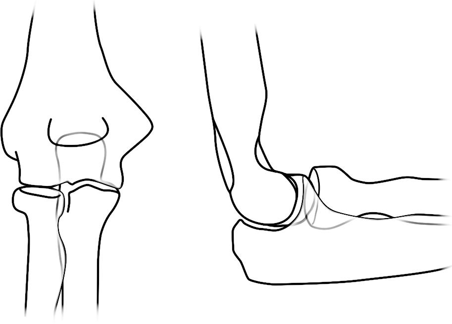
The Primer is a short, illustrated text highlighting the specific imaging features of the common fractures and dislocations related to the area under consideration. This discussion is augmented with anatomic drawings of the skeletal system as seen on radiographs (Figures 1-1A and B). They show the sites and course of the common fractures in red lines: the most common fractures in thick red lines and the less common in thin red lines.
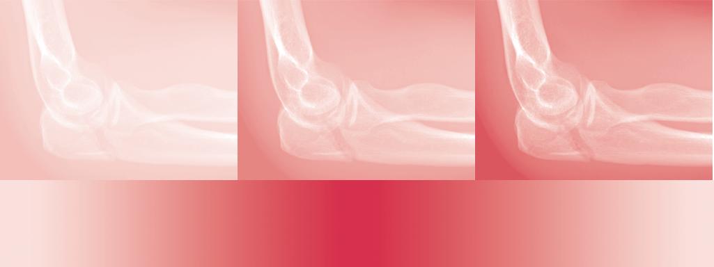
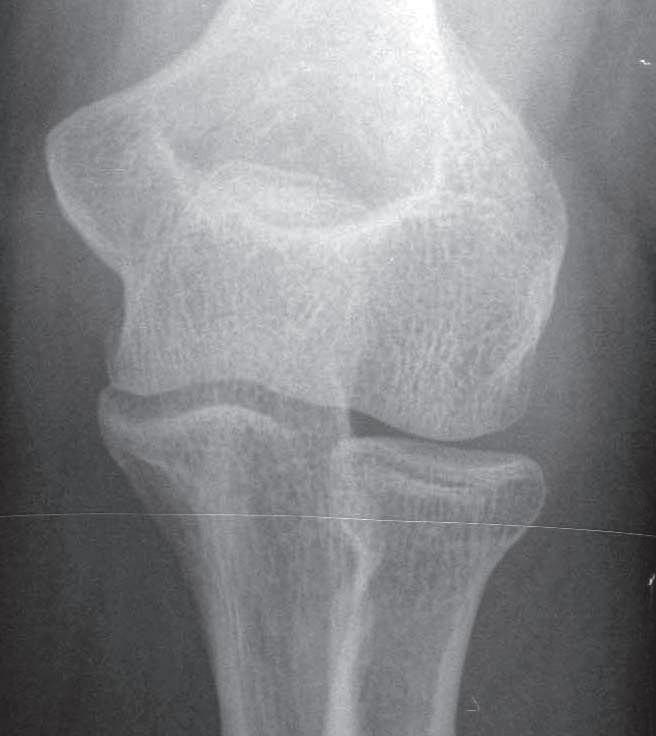
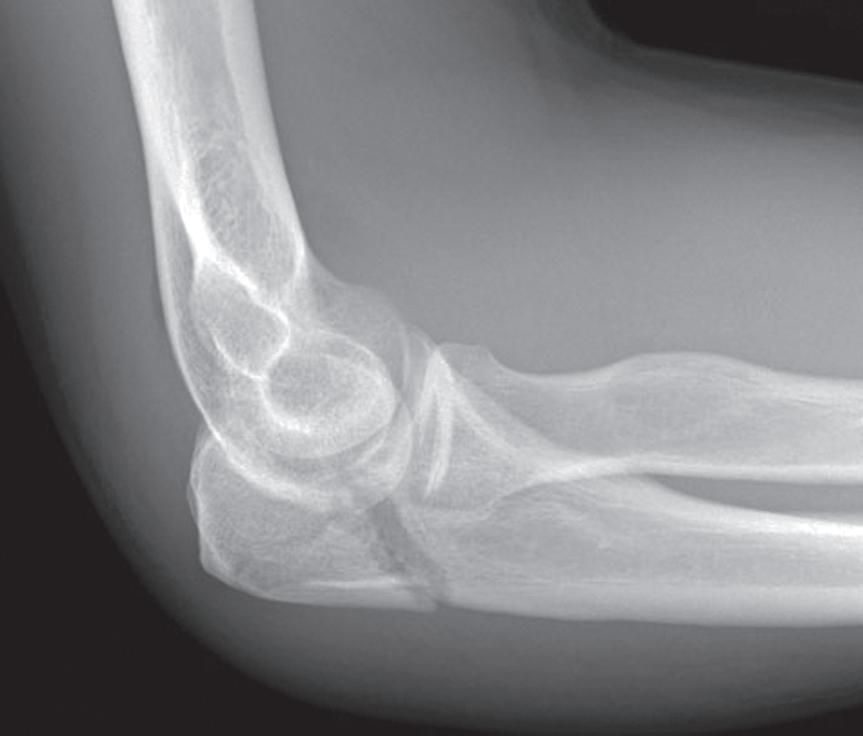
A series of select high-quality clinical radiographs, CT, and MRI images illustrates the principal findings described in the text covering each separate checklist. Fractures of the radial head (Figure 1-2A) and olecranon (Figure 1-2B) are shown. Once armed with this disciplined approach, the ability to interpret images of skeletal trauma is enhanced. One becomes more comfortable and confident in an ability to assess skeletal trauma. The end result is greater accuracy and a substantial reduction in the ever-present fear of overlooking and failing to diagnose significant injuries.
FIGURE 1-1 A, B, Anatomic drawings of the skeletal system as seen on radiographs.
FIGURE 1-2 Fractures of the radial head (A) and olecranon (B).
Suggested Readings
Checklists
1. Haynes AB, et al. A surgical safety checklist to reduce morbidity and mortality in a global population. New England Journal of Medicine 2009;360:491–499.
2. Gawande A The Checklist Manifesto. New York: Metropolitan Books, Henry Holt and Company; 2009.
3. Levin DC. Checklists: From the cockpit to the radiology department. Journal of the American College of Radiology. 2012;9:388–390.
Satisfaction of Search
4. Ashman CJ, Yu JS, Wolfman D. Satisfaction of search in osteoradiology. American Journal of Roentgenology. 2000;177:252–253.
5. Berbaum KS, El-Khoury GY, Franken Jr , et al. Missed fractures resulting from satisfaction of search effect. Emergency Radiology. 1994;1:242–249.
6. Fleck MS, Samei E, Mitroff SR. Generalized “satisfaction of search”: Adverse influences on dual-target search accuracy. J Exp Psychol Appl 2010 Mar;16(1):60–71. http://dx.doi.org/10.1037/a0018629
Missing Fractures
7. Berlin L. Defending the “Missed” radiographic diagnosis. American Journal of Roentgenology. 2001;176(2):317–322
8. Hu CH, Kundell HL, Nodine CF, et al. Searching for bone fractures: a comparison with pulmonary nodule search. Acad. Radiol. 1994;1:25–32
9. Pinto A, Brunese L. Spectrum of diagnostic errors in radiology. World J Radiol. 2010;2:377–383
10. Robinson PJ, Wilson D, Coral A, et al. Variation between experienced observers in the interpretation of accident and emergency radiographs. Br J Radiol. 1999;72:323–330.
11. Tuddenham WJ. Visual search, image organization, and reader error in roentgen diagnosis: Studies of the psycho-physiology of roentgen image perception. Radiology. 1962;78:694–704
12. Wood G, Knapp KM, et al. Visual expertise in detecting and diagnosing skeletal fractures. Skeletal Radiol. 2013;42:165–172
Shoulder CheCkliStS
1. Radiographic examination
AP external rotation
AP internal rotation
Axillary view
Y-view
Grashey (posterior oblique) view
2. Common sites of injury in adults
Fractures
Midshaft of clavicle
Avulsion of the greater tuberosity of the humerus
Surgical neck of the humerus
Dislocations
Acromioclavicular joint dislocation
Dislocation of the glenohumeral joint
Anterior dislocation
Posterior dislocation
Luxatio erecti
3. Common sites of injury in children and adolescents
Greenstick fracture midshaft of clavicle
Acromioclavicular joint dislocation
Epiphyseal separation proximal humerus
Pathologic fracture of unicameral bone cyst (UBC) of proximal humerus
4. Injuries likely to be missed
Posterior dislocation of the shoulder (glenohumeral) joint
Injuries in and about the sternoclavicular joint
Sternoclavicular dislocations
Fractures of the medial clavicle
5. Where to look when you see nothing at all
Check again for findings to suggest a posterior dislocation of the glenohumeral joint.
Is the joint space widened?
Is the humeral head fixed in internal rotation?
Look closely at the rim of the glenoid fossa, particularly the anterior rim, on the AP view.
Is the ovoid rim intact?
CHAPTER 2
The Shoulder
Look for a subtle, nondisplaced fracture of the mid-clavicle.
Need clear view of the mid-clavicle, free of the underlying ribs and scapula.
AP view with 15° of cephalic angulation may be required to disclose the fracture.
Shoulder – the Primer
1. Radiographic examination
AP external rotation
AP internal rotation
Axillary view
Y-view
Grashey (posterior oblique) view
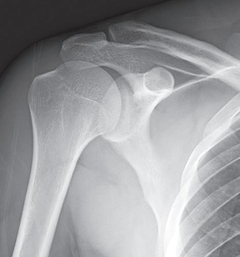
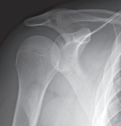
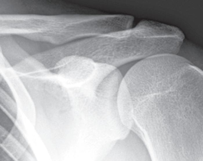
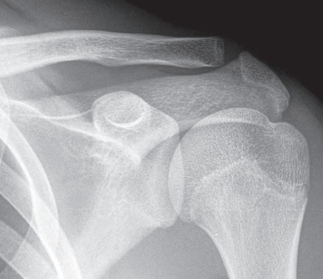
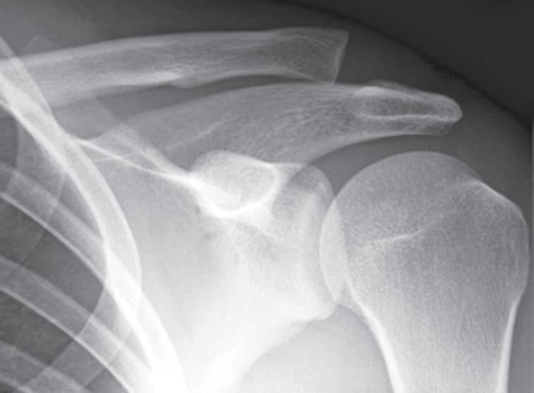
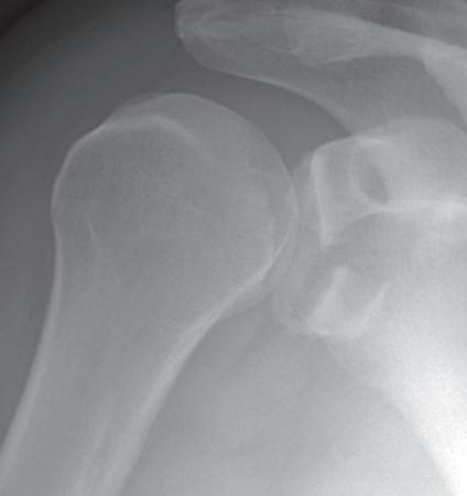
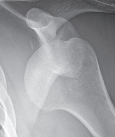
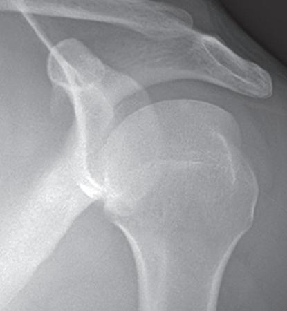
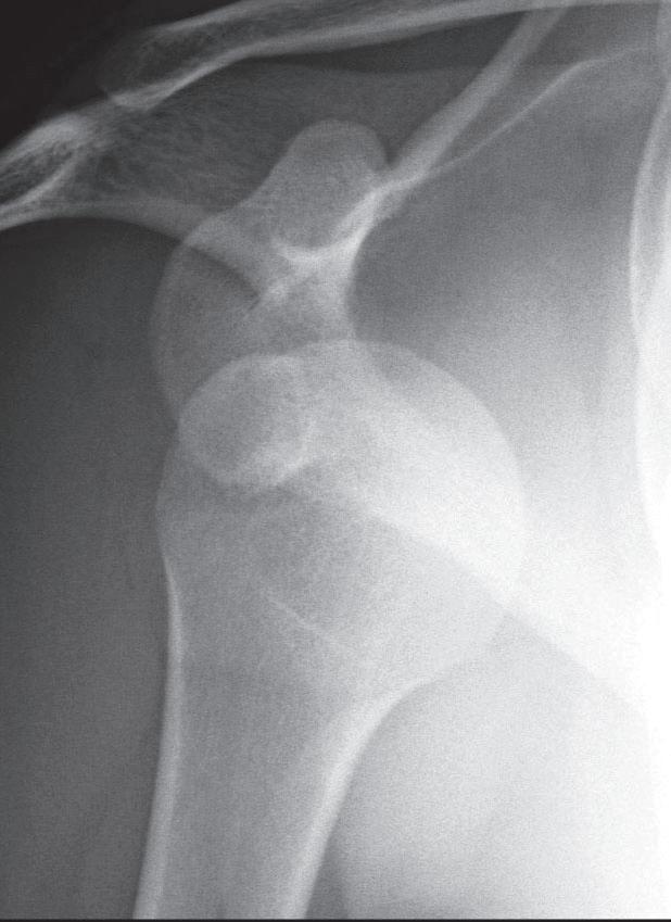
The standard radiographic examination of the traumatized shoulder should include at least three of the five standard views listed above. These have been selected because they have proven to disclose the majority of fractures and dislocations. My personal preferences are the four illustrated (Figure 2-1). Two AP views should be obtained, one with the humerus in external rotation and the second with the humerus in internal rotation (Figure 2-1A, B). The Grashey or posterior oblique view (Figure 2-1C) is a tangential view of the glenohumeral joint obtained with 35° posterior rotation of the shoulder. This view is particularly useful in disclosing fractures of the anterior glenoid rim and confirming the presence of a posterior (glenohumeral) shoulder dislocation as identified by an overlap of the humeral head and glenoid in this projection.
The axillary view (Figure 2-1D) also depicts the glenohumeral joint and margins of the glenoid to good advantage and therefore is useful in identifying glenoid rim and coracoid fractures as well as dislocations of the glenohumeral joint.
2.
Common
Fractures
sites of injury in adults
Midshaft of clavicle
Avulsion of the greater tuberosity of the humerus
Surgical neck of the humerus
Dislocations
Acromioclavicular joint dislocation
Dislocations of the glenohumeral joint
Anterior dislocation
Posterior dislocation
FIGURE 2-1 The standard radiographic examination of the traumatized shoulder. Two AP views should be obtained, one with the humerus in external rotation (A) and the second with the humerus in internal rotation (B) C, The Grashey or posterior oblique view is a tangential view of the glenohumeral joint obtained with 35° posterior rotation of the shoulder. D, The axillary view depicts the glenohumeral joint and margins of the glenoid to good advantage.
Pattern of search. Diagrams of the shoulder (Figure 2-2) pinpoint the common sites of fracture and dislocation in adults. The most common sites of fracture are identified by broad red lines. Less common sites are designated by fine red lines. Your pattern of search should include all sites.
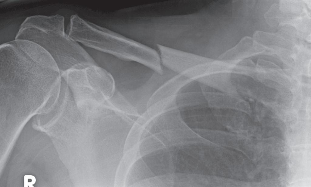
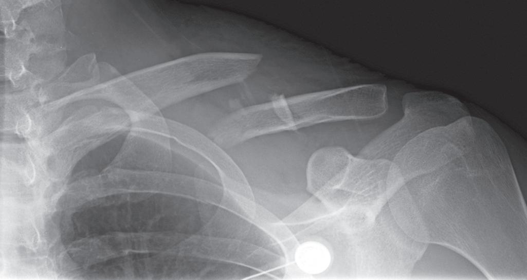
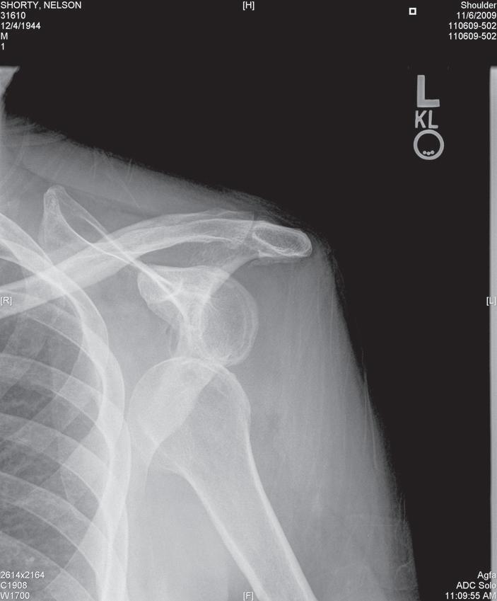
Clavicle fractures. Eighty plus percent of fractures occur in the midshaft. They may be nondisplaced (Figure 2-3A) or displaced and comminuted, commonly with elevation of the medial fragment (Figure 2-3B). Fractures of the outer third may involve the AC joint and disrupt the coracoclavicular ligament. Fractures of the medial third are uncommon.
Acromioclavicular dislocations. In the normal AC joint the inferior cortex of the outer end of the clavicle aligns with the under-surface of the acromion (Figures 2-4A). The width of the normal AC joint is 4 to 6 mm. The normal distance between the superior tip of the coracoid process and inferior surface of the adjacent clavicle is approximately 1.2 cm. Disruption of the coracoclavicular ligaments results in an increase in this distance.
Acromioclavicular dislocations vary from a simple sprain manifest by widening of the AC joint, to disruption of the
joint with slight elevation of the clavicle with intact coracoclavicular ligaments (Figure 2-4B), to complete disruption of the joint with elevation of the outer end of the clavicle and tears of the coracoclavicular ligaments increasing the coraclavicular distance (Figure 2-4C).
Acromioclavicular dislocations may require weight-bearing views to disclose the true extent or even the presence or absence of injury. Weight-bearing views are not required if the outer clavicle is elevated and the coracoclavicular distance is increased above 1.2 cm. In any other circumstance with a clinical suspicion of AC joint injury, weight-bearing views should be obtained to determine the full extent of the injury.
Rockwood classification of AC joint dislocations (Figure 2-5). Type I consists of a sprain of the ligaments about the
FIGURE 2-3 A, Undisplaced clavicle fracture. B, Displaced and comminuted clavicle fracture.
FIGURE 2-2 Diagrams of the shoulder pinpoint the common sites of fracture and dislocation in adults.
FIGURE 2-4 A, Normal acromioclavicular joint where the inferior cortex of the outer end of the clavicle aligns with the under-surface of the acromion. B, Acromioclavicular dislocation with slight elevation of the clavicle with intact coracoclavicular ligaments. C, Complete disruption of the joint with elevation of the outer end of the clavicle and tears of the coracoclavicular ligaments increasing the coracoclavicular distance.
TypeITypeII
TypeIIITypeIV
TypeVTypeVI
FIGURE 2-5 Rockwood classification of AC joint dislocations. Type I consists of a sprain of the ligaments about the joint. There is no displacement of the clavicle or widening of the joint. The radiographic findings are normal. Type II is a subluxation of the AC joint. The outer end of the clavicle is slightly elevated in relation to the acromion, and the AC joint may be widened, but the clavicular ligaments remain intact, and the coracoclavicular distance is normal. In Type III the coracoclavicular ligaments are disrupted, and the distance between the clavicle and coracoid is increased, >1.2 cm. The clavicle is elevated. Type IV is a posterior dislocation of the clavicle. The outer end of the clavicle pierces into or through the trapezius muscle. The clavicle may be elevated or, at times, depressed. Posterior displacement can be seen on the axillary or Y views. In Type V the clavicle is markedly elevated and lies subcutaneously. The clavicle is at least partially detached from its muscle attachments. Type VI is an inferior dislocation wherein the outer end of the clavicle comes to rest beneath the coracoid process posterior to the coracobrachialis tendon.
joint. There is no displacement of the clavicle or widening of the joint. The radiographic findings are normal. Type II is a subluxation of the AC joint. The outer end of the clavicle is slightly elevated in relation to the acromion, and the AC joint may be widened, but the clavicular ligaments remain intact, and the coracoclavicular distance is normal. In Type III the coracoclavicular ligaments are disrupted, and the distance between the clavicle and coracoid is increased >1.2 cm. The clavicle is elevated. Type IV is a posterior dislocation of the clavicle. The outer end of the clavicle pierces into or through the trapezius muscle. The clavicle may be elevated or, at times, depressed. Posterior displacement can be seen on the axillary or Y views. In Type V the clavicle is markedly elevated and lies subcutaneously. The clavicle is at least partially detached from its muscle attachments. Type VI is an inferior dislocation wherein the outer end of the clavicle comes to rest beneath the coracoid process posterior to the coracobrachialis tendon.
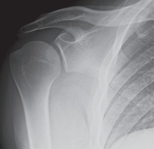
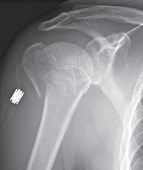
Proximal humerus fractures. Avulsions of the greater tuberosity occur either in isolation or in association with fractures of the surgical neck of the humerus (Figure 2-6A). Fractures of the surgical neck are particularly common in the elderly with or without (Figure 2-6B) associated avulsions of the greater tuberosity.
With fractures of the humeral head and/or neck, the humeral head may be displaced inferiorly giving the appearance of an
inferior dislocation of the glenohumeral joint (Figure 2-6B). The displacement is due to a large volume hemarthrosis that commonly accompanies these fractures and is not considered to be a true dislocation. It is therefore referred to as a “pseudodislocation.” As the hemarthrosis resorbs, the normal relationship of the humeral head and glenoid is restored.
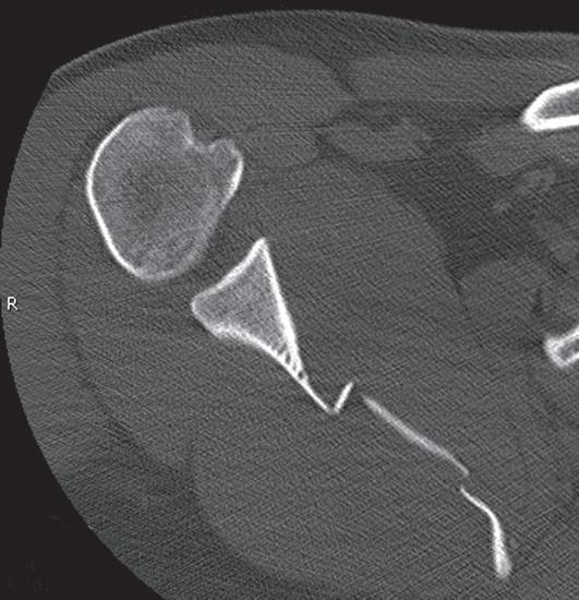
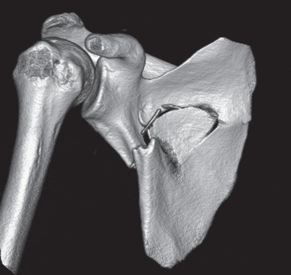
Scapular fractures. The body of the scapula is rarely injured in simple falls; most occur in motor vehicle collisions. Fractures can be identified on radiographs of the chest (Figure 2-7A) but are much more clearly depicted by CT, particularly CT of the chest (Figures 2-7B and C), which is nearly always obtained in those who have sustained high impact trauma. The full extent of scapular fractures is best disclosed by CT with 3-D reconstruction (Figures 2-7C and 2-8C).
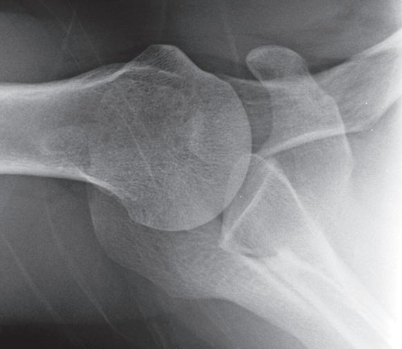
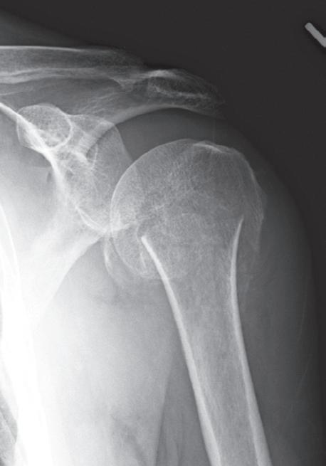
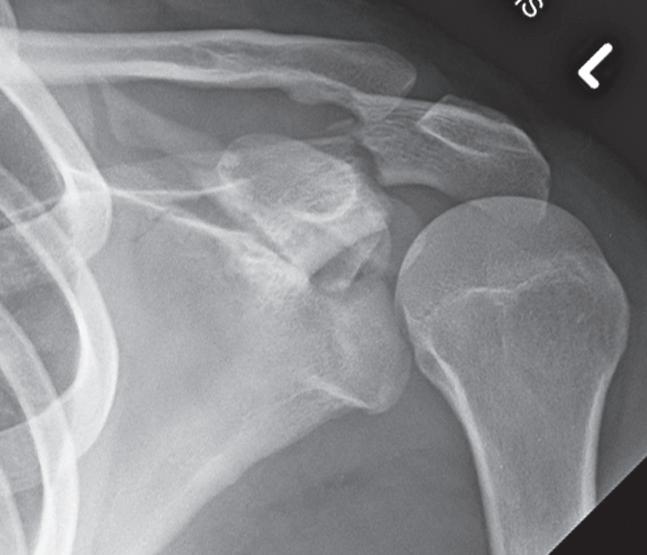
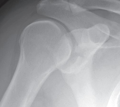
Scapular fractures involving the glenoid, acromion, and coracoid process also occur in association with glenohumeral and/or acromioclavicular dislocations (Figure 2-8). Fractures of the acromion, coracoid process, and superior border of scapula associated with a posterior dislocation of the glenohumeral joint are shown in Case 1 (Figure 2-8A). Note the humeral head is in internal rotation, and the distance between it and the anterior rim of the glenoid is widened indicating a posterior dislocation of the glenohumeral joint (Figure 2-8A).
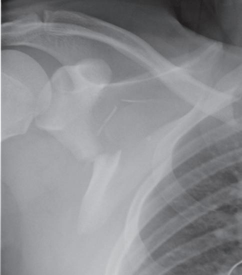
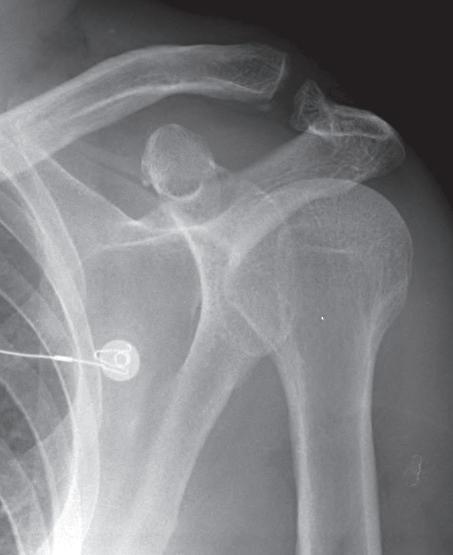
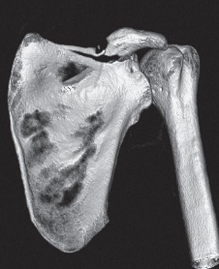
In Case 2 (Figures 2-8B and C) an acromioclavicular dislocation and fracture of the superior border of the scapula and coracoid are shown. Note AC dislocation and associated fracture of acromion. The scapular fracture is barely visible on this AP view of the shoulder (Figure 2-8B). However, this fracture of the superior border of the scapula is nicely shown by CT 3-D reconstruction (Figure 2-8C).
Fractures of the glenoid rim are created by an impact of the humeral head against the anterior inferior margin of the glenoid during a transient or complete anterior dislocation of the glenohumeral joint. The fracture fragment is displaced inferior and medial. The fracture is usually better seen on the post-reduction radiographs. Look closely at the anterior rim of the glenoid on the AP projections (Figure 2-9A). Is the ovoid rim density intact? Anterior glenoid rim fractures are best seen on the Grashey projection (Figure 2-9B) or axillary view. Obtain these views if you have not already done so. If questionable, quit fooling around; get a CT.
Fracture of the anterior inferior glenoid rim associated with an anterior dislocation of the glenohumeral joint is shown in Figures 2-9C and D. The initial AP view clearly demonstrates the subcoracoid anterior dislocation (Figure 2-9C). Note: underlying the humeral head is a small bony fragment
FIGURE 2-6 Proximal humerus fractures. A, Avulsions of the greater tuberosity occur either in isolation or in association with fractures of the surgical neck of the humerus. B, Fractures of the surgical neck are particularly common in the elderly with or without associated avulsions of the greater tuberosity.
FIGURE 2-7 Scapular fractures. A, Radiograph of the chest. B, (Axial) C, (3D reformat) CTs of the chest.
adjacent to the glenoid at the 7 o’clock position. This is an avulsion fracture of the glenoid rim. There is also a small bony fragment just interior to the medial margin of the coracoid on this view. Note that this small glenoid rim fracture is better seen on the postreduction AP view (Figure 2-9D).
Glenohumeral dislocations. Dislocations are more common in the shoulder than at other major joints. Anterior dislocations account for 95% of all glenohumeral dislocations. The humeral
head is displaced anterior, medial, and inferior, coming to rest beneath either the coracoid process (subcoracoid) (Figure 2-10A) or glenoid process (subglenoid) (Figure 2-10B).
Subcoracoid is by far the most common. Fractures of the anterior inferior rim of the glenoid are frequent and often best seen on the postreduction views (see Figure 2-9).
A characteristic impaction fracture of the humeral head may occur during an anterior dislocation as the humeral head becomes impaled on the anterior inferior margin of the glenoid
2-10 Glenohumeral dislocations are more common in the shoulder than at other major joints. Anterior dislocations account for 95% of all glenohumeral dislocations. The humeral head is displaced anterior, medial, and inferior, coming to rest beneath either the coracoid process (subcoracoid) (A) or glenoid process (subglenoid) (B).
FIGURE 2-8 A, B, C, Scapular fractures involving the glenoid, acromion, and coracoid process also occur in association with glenohumeral and/or acromioclavicular dislocations.
FIGURE 2-9 A, An anterior glenoid rim fracture on AP projection. B, Anterior glenoid rim fractures are best seen on the Grashey projection or axillary view. C, D, Fracture of the anterior inferior glenoid rim associated with an anterior dislocation of the glenohumeral joint.