Foundation and Anchor Design Guide for Metal Building Systems 1st Edition, (Ebook PDF)
Visit to download the full and correct content document: https://ebookmass.com/product/foundation-and-anchor-design-guide-for-metal-buildin g-systems-1st-edition-ebook-pdf/
More products digital (pdf, epub, mobi) instant download maybe you interests ...
Handbook for Building Construction: Administration, Materials, Design, and Safety Clifford J Schexnayder
https://ebookmass.com/product/handbook-for-building-constructionadministration-materials-design-and-safety-clifford-jschexnayder/
Solution Architecture Patterns for Enterprise: A Guide to Building Enterprise Software Systems 1st Edition
Chanaka Fernando
https://ebookmass.com/product/solution-architecture-patterns-forenterprise-a-guide-to-building-enterprise-software-systems-1stedition-chanaka-fernando/
Handbook for Building Construction: Administration, Materials, Design, and Safety 1st Edition Schexnayder
https://ebookmass.com/product/handbook-for-building-constructionadministration-materials-design-and-safety-1st-editionschexnayder/
(eBook PDF) Systems Analysis and Design, 12th Edition
https://ebookmass.com/product/ebook-pdf-systems-analysis-anddesign-12th-edition/
Feedstock Technology for Reactive Metal Injection
Molding: Process, Design, and Application 1st Edition Peng Cao
https://ebookmass.com/product/feedstock-technology-for-reactivemetal-injection-molding-process-design-and-application-1stedition-peng-cao/
Cracking the Code: Introduction to Machine Learning for Novices: Building a Foundation for Artificial Intelligence 1st Edition Sarah Parker
https://ebookmass.com/product/cracking-the-code-introduction-tomachine-learning-for-novices-building-a-foundation-forartificial-intelligence-1st-edition-sarah-parker/
Database Systems Design, Implementation, and Management 12th Edition (eTextbook) PDF
https://ebookmass.com/product/database-systems-designimplementation-and-management-12th-edition-etextbook-pdf/
Tidal Energy Systems: Design, Optimization and Control 1st Edition
https://ebookmass.com/product/tidal-energy-systems-designoptimization-and-control-1st-edition/
Complete Casting Handbook: Metal Casting Processes, Metallurgy, Techniques and Design 2nd Edition – Ebook PDF Version
https://ebookmass.com/product/complete-casting-handbook-metalcasting-processes-metallurgy-techniques-and-design-2nd-editionebook-pdf-version/
Foundation and Anchor Design Guide for Metal Building Systems
This page intentionally left blank
Foundation and Anchor Design Guide for Metal Building Systems
Alexander Newman, P.E., F.ASCE
Copyright © 2013 by The McGraw-Hill Companies. All rights reserved. Except as permitted under the United States Copyright Act of 1976, no part of this publication may be reproduced or distributed in any form or by any means, or stored in a database or retrieval system, without the prior written permission of the publisher.
ISBN: 978-0-07-176634-0
MHID: 0-07-176634-0
The material in this eBook also appears in the print version of this title: ISBN: 978-0-07-171951-3, MHID: 0-07-176635-9.
McGraw-Hill eBooks are available at special quantity discounts to use as premiums and sales promotions, or for use in corporate training programs. To contact a representative please e-mail us at bulksales@mcgraw-hill.com.
All trademarks are trademarks of their respective owners. Rather than put a trademark symbol after every occurrence of a trademarked name, we use names in an editorial fashion only, and to the benefit of the trademark owner, with no intention of infringement of the trademark. Where such designations appear in this book, they have been printed with initial caps.
Information has been obtained by McGraw-Hill from sources believed to be reliable. However, because of the possibility of human or mechanical error by our sources, McGraw-Hill, or others, McGraw-Hill does not guarantee the accuracy, adequacy, or completeness of any information and is not responsible for any errors or omissions or the results obtained from the use of such information.
Information contained in this work has been obtained by The McGraw-Hill Companies, Inc. (“McGraw-Hill”) from sources believed to be reliable. However, neither McGraw-Hill nor its authors guarantee the accuracy or completeness of any information published herein, and neither McGraw-Hill nor its authors shall be responsible for any errors, omissions, or damages arising out of use of this information. This work is published with the understanding that McGraw-Hill and its authors are supplying information but are not attempting to render engineering or other professional services. If such services are required, the assistance of an appropriate professional should be sought.
TERMS OF USE
This is a copyrighted work and The McGraw-Hill Companies, Inc. (“McGrawHill”) and its licensors reserve all rights in and to the work. Use of this work is subject to these terms. Except as permitted under the Copyright Act of 1976 and the right to store and retrieve one copy of the work, you may not decompile, disassemble, reverse engineer, reproduce, modify, create derivative works based upon, transmit, distribute, disseminate, sell, publish or sublicense the work or any part of it without McGraw-Hill’s prior consent. You may use the work for your own noncommercial and personal use; any other use of the work is strictly prohibited. Your right to use the work may be terminated if you fail to comply with these terms.
THE WORK IS PROVIDED “AS IS.” McGRAW-HILL AND ITS LICENSORS MAKE NO GUARANTEES OR WARRANTIES AS TO THE ACCURACY, ADEQUACY OR COMPLETENESS OF OR RESULTS TO BE OBTAINED FROM USING THE WORK, INCLUDING ANY INFORMATION THAT CAN BE ACCESSED THROUGH THE WORK VIA HYPERLINK OR OTHERWISE, AND EXPRESSLY DISCLAIM ANY WARRANTY, EXPRESS OR IMPLIED, INCLUDING BUT NOT LIMITED TO IMPLIED WARRANTIES OF MERCHANTABILITY OR FITNESS FOR A PARTICULAR PURPOSE. McGraw-Hill and its licensors do not warrant or guarantee that the functions contained in the work will meet your requirements or that its operation will be uninterrupted or error free. Neither McGraw-Hill nor its licensors shall be liable to you or anyone else for any inaccuracy, error or omission, regardless of cause, in the work or for any damages resulting therefrom. McGraw-Hill has no responsibility for the content of any information accessed through the work. Under no circumstances shall McGraw-Hill and/or its licensors be liable for any indirect, incidental, special, punitive, consequential or similar damages that result from the use of or inability to use the work, even if any of them has been advised of the possibility of such damages. This limitation of liability shall apply to any claim or cause whatsoever whether such claim or cause arises in contract, tort or otherwise.
About the Author
Alexander Newman, P.E., F.ASCE, is a forensic and structural consultant in Needham, Massachusetts. During more than 30 years of professional practice, he has been involved with the structural design, renovation, and failure investigation of numerous structures around the country. His areas of expertise include design and failure analysis of pre-engineered metal buildings, metal roofs, and other structures. He is one of the country’s foremost experts on metal building systems. He has served as an expert consultant for litigation involving metal building systems and other structures.
Mr. Newman’s diverse engineering and managerial experience includes positions as principal structural engineer with a large architectural and engineering firm, manager of a steel fabrication shop, and engineer with light-gage metal and precast-concrete manufacturers. Most recently, he has been a managing engineer with Exponent Failure Analysis Associates, the country’s premier construction failure and accident investigation firm.
Mr. Newman’s many publications include a number of award-winning articles that appeared in leading engineering magazines. His definitive reference book Structural Renovation of Buildings: Methods, Details, and Design Examples was published by McGraw-Hill in 2001. He is the author of another authoritative book from McGraw-Hill, Metal Building Systems: Design and Specifications, now in its Second Edition and translated into Chinese.
Mr. Newman has led numerous educational seminars around the country for design professionals, building officials, owners, and contractors. He has conducted training programs for the employees of the U.S. State Department, NASA, the U.S. Air Force, the Iraq Reconstruction Team, and many educational and professional groups. He has taught a number of courses at Northeastern University.
This page intentionally left blank
Chapter 1 Introduction to Metal Building Systems
1.1 Two Main Classes of Metal Building Systems
The purpose of this chapter is to introduce the reader to metal building systems (MBS) and to explain how they work. These structures, also known as pre-engineered metal buildings and sometimes abbreviated as PEMBs, are both designed and manufactured by their suppliers. In this book the terms metal building systems, metal buildings, preengineered buildings, and pre-engineered metal buildings are used interchangeably.
Metal buildings are extremely popular in the United States. Many, if not most, low-rise nonresidential buildings there contain pre-engineered structures. Reasons for the popularity of these systems include their cost-effectiveness, speed of construction, single-source responsibility for the superstructure, ease of maintenance, and the ability to span long distances without intermediate supports.
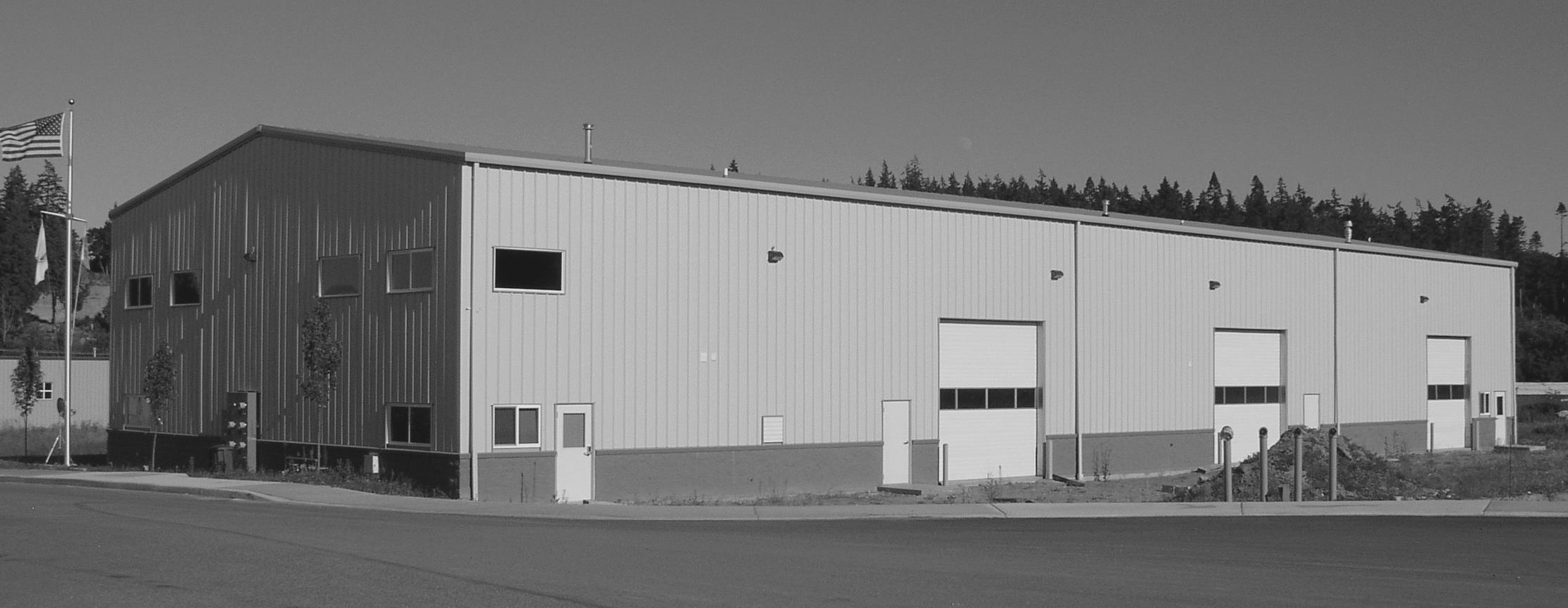
Metal building systems can be found in all types of buildings. Approximately one-third of them are used in commercial applications, such as office buildings, retail stores, and garages. Another one-third include manufacturing uses, such as factories, production plants, and material recycling facilities (see Fig. 1.1). The rest are used in community buildings (schools, churches, municipal), agricultural, and storage occupancies (Newman, 2004).
The two main classes of metal building systems are frame-and-purlin and Quonset hut–type buildings. Both are described in this chapter, but our main focus is on the former. From the foundation designers’ point of view, there is a fundamental difference between the two classes of metal buildings.
1.2 Frame-and-Purlin Buildings: Primary and Secondary Framing
As the name suggests, this class of metal building systems includes separate primary frames and secondary members. The primary frames (also called main frames) can be of various types. The foundation design is greatly influenced by the type of primary frame selected for the building. For example, some frame types tend to exert significant lateral reactions on the supports and others do not.
The primary frames carry secondary roof members called purlins and secondary wall members called girts. At the intersection of the roof and wall panels typically exists the third type of secondary member, known by the names of eave girt, eave purlin, or eave strut. The various names reflect the versatile nature of this important element that can wear three hats: a girt, a purlin, and an axially loaded structural member. Axial loading comes into play when the strut resists lateral forces as part of the cross-bracing assembly in the wall.
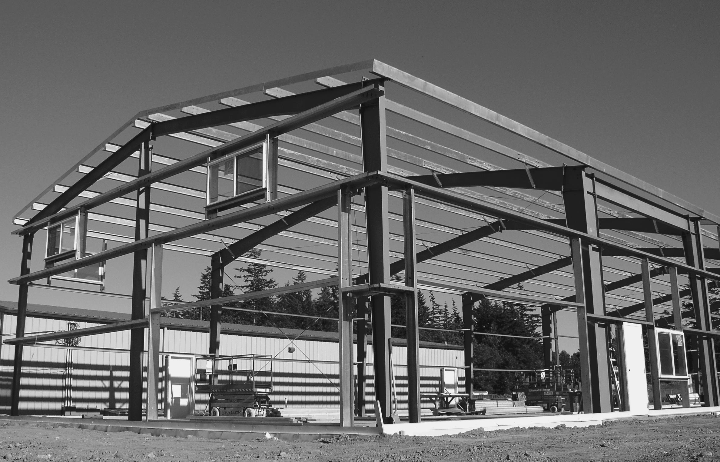
The secondary members support metal panels or other roof and wall cladding. In pre-engineered buildings, endwalls are at the ends of the building parallel to the primary frames, while sidewalls are perpendicular to the frames. The typical components of the frame-and-purlin system are shown in Fig. 1.2.
Figure 1.2 Typical components of the frame-and-purlin system.
Girt
Bracing
Roof system
Roof purlin
Eave strut
Endwall frame
Rigid frame
Frame width Clear span
Rigid frame column
Bay spacing
Eave height
Figure 1.1 Metal building system used in an industrial facility.
The Metal Building Manufacturers Association (MBMA) is the trade group that includes most major manufacturers of pre-engineered metal buildings. Metal Building System Manual (MBMA, 2006) provides a wealth of information related to the design, fabrication, and procurement of frame-and-purlin pre-engineered metal buildings.
1.2.1 Primary Frames: Usage and Terminology
Primary frames are the backbone of the frame-and-purlin metal building system. The available primary frame systems vary significantly in their design assumptions, structural behavior, column configuration, and, perhaps most important for the reader, in the magnitude of the horizontal column reactions exerted on the foundations. Some of the considerations involved in the selection of the primary frames include:
• Width, length, and height of the building
• Acceptability of tapered columns
• Slope of the roof
• Clear-span requirements
• Wall and roof materials
Each frame consists of a rafter and at least two columns. The joint between an exterior column and the rafter is called the knee . A clear span is the distance between the inside faces of the frame columns. Each of the primary frame types has an optimum range of clear spans. The clear span can be measured between the frame knees, as shown in Fig. 1.2, but it can also be measured between the inside faces of the columns at the base.
A similar term, frame width, refers to the distance between the outside faces of the wall girts, a plane that is called the sidewall structural line. Looking at Fig. 1.2, please also note that for a single-story building the clear height is the distance between the floor and the lowest point of the frame at the roof level. Also, the eave height is the distance between the bottom of the column base plate and the top of the eave strut.
The rafter is usually spliced, with the dimensions of the individual segments finetuned for the applied bending moments and shears at those locations. The variability of the frame cross-section tends to complicate the analysis but saves metal by improving the framing efficiency. The splices are typically made at the peak, at the knees, and at the intermediate locations determined by the manufacturer’s preferences.
Certain types of frames, such as a single-span rigid frame, can resist lateral (wind and seismic) forces acting in the direction parallel to the frames. Others require separate vertical and horizontal lateral-force-resisting elements in addition to the frames, as discussed in Sec. 1.3.
1.2.2 Single-Span Rigid Frames
The single-span rigid frame system is perhaps the most familiar and versatile type of primary framing used in pre-engineered buildings. These frames can be found in a wide variety of applications, from warehouses to churches. The frame profile is tapered to approximate the shape of the frame’s moment diagram. A single-span rigid frame can be of either two- or three-hinge design. An example of two-hinge rigid frame can be found in Fig. 1.2; a three-hinge frame design is shown in Fig. 1.3a
Figure 1.3 Common types of primary frames used in metal building systems and the gravity-load reactions they generate: (a) Single-span rigid frame; (b) multiple-span rigid frame; (c) tapered beam; (d) truss.
The knee is typically the deepest point of the tapered frame profile, making this system appropriate for the buildings where the clear height at the exterior walls is not critical. In this type of construction, the tallest equipment can be placed near the middle of the span or between the frames.
The single-span rigid frame provides a significant column-free area and the maximum flexibility for the user. The most economical frame width for this system lies between 60 and 120 ft, although frames over 200 ft wide have been produced. The most common range of the eave heights is from 10 to 24 ft.
The degree of rafter slope depends on the type of the roof used in the building. The low-slope frames, with a pitch from ¼:12 to 1:12, are appropriate for waterproof (hydrostatic) metal and nonmetal roofs. The medium-slope frame profile has a pitch of about 2:12, which works well with “waterproof” metal roofs in the regions where heavy snow accumulation is common. And finally, the high-profile frames, with a pitch of 3:12 or 4:12, are used with steep-slope (hydrokinetic) roofing systems. The different types of metal roofing are discussed in Newman (2004) and in Roofing Systems Design Manual (MBMA, 2000).
A single-span rigid frame typically exerts significant horizontal reactions on the foundations under gravity loading. The smaller the eave height, the larger these horizontal reactions tend to become.
1.2.3 Multiple-Span Rigid Frames
When the frame width of the building exceeds the limitations of the single-span rigid frame system, intermediate columns can be added. The resulting system is called the
multiple-span rigid frame, also known as continuous-beam, post-and-beam, and modular frame (Fig. 1.3b). Multiple-span rigid frames can be more economical than their singlespan siblings, even within the theoretical range of the optimum efficiency of the latter. However, the added columns obviously diminish the building’s flexibility of use, a factor that might outweigh any potential cost savings. Accordingly, multiple-span rigid frames are best used in buildings with relatively static layout, such as factories with mature processes, large warehouses, and resource-recovery facilities.
Even with the multiple-span rigid frame system, the overall building width is constrained by the limitations imposed by thermal movement considerations. A very long frame without external restraints to movement will tend to expand and contract so much with the seasonal changes in temperature that the building’s dimensional stability might become compromised. Alternatively, if the combination of the secondary framing, metal cladding, and bracing restrains the temperature-induced movements of the frame, thermal stresses might build up significantly. As a practical matter, expansion joints are usually needed when the building width exceeds about 300 ft.
Exterior columns in this system are usually tapered, and interior columns are straight, made of either pipe or W shapes. Interior columns are often assumed to have pinned connections to the rafters, and their horizontal reactions on the foundations are typically negligible. By contrast, the horizontal reactions at the bases of the exterior columns under gravity loading could be significant.
Unlike single-span rigid frames, multiple-span rigid frames can be adversely affected by the differential settlements of their supports. As we discuss in Chap. 2, some amount of foundation settlement is often unavoidable. When the interior frame columns settle at a rate different from that of the exterior columns, the continuous frame might become overstressed. Vulnerability to differential settlement is one of the few disadvantages of this otherwise very economical structural system.
1.2.4 Tapered Beam
The tapered beam, sometimes called a wedge beam, is similar to a conventional built-up plate girder, with two important differences. One, as the name suggests, is the tapered profile of the rafter. The second difference has to do with the manner in which the tapered beam is connected to the column, as discussed next.
In the most common version, the top surface of the beam is tapered, and the bottom surface is horizontal. This design solution allows the top of the roof to slope for drainage. A less common design has both flanges tapered, analogous to a scissors truss. A splice is typically made at the midspan of the beam. The columns in this system are usually of the straight profile. The tapered-beam system works best with a low-slope roof profile, as the rafter becomes too deep in steep-slope applications.
The tapered-beam system can be economical for relatively small frame widths— between 30 and 60 ft. Beyond 60 ft, single-span rigid frames typically become more cost-effective. The eave height in this system usually does not exceed 20 ft. Tapered beams are well suited for small office buildings and other commercial applications, particularly where ceilings are desired.
The tapered beam is typically connected to the column by bolted end plates. Some manufacturers consider this a semirigid (partially restrained) connection—rigid enough to resist lateral loads but flexible enough to allow for a simple-span beam behavior under gravity loading. The idea of the “wind” connections of this kind has been popular in the past, but today such simplistic assumptions are out of favor. Contemporary AISC Specification (2005) recognizes this type of attachment as “partially restrained (PR)
moment connection.” These are treated as moment connections, but with an understanding that the rotation between the connected members is not negligible as in fully restrained moment connections. According to the Specification, the design of a PR connection must consider its force-deformation response characteristics, properly documented by prior research, analysis, or testing.
From a practical standpoint, the end-plate connection behavior depends on the design details. For example, the AISC Manual (2005) includes the design provisions for extended end-plate fully restrained moment connections and provides further references to the AISC Design Guides. But the manual also recognizes, and provides the design tables for, shear (simple-span) end-plate connections, where the moment resistance is neglected. To qualify for this assumption, the end-plate length must be less than the depth of the beam to which it is attached.
It follows that a rafter and two columns joined by the full-depth or extended endplate connections should probably be treated as a PR rigid frame, similar to the singlespan rigid frame examined previously. Under this assumption the columns are designed for the fixity moments at the knees.
What is the importance of this discussion for the foundation designer? The actual behavior of the tapered-beam system affects the magnitude of the column reactions. The moment-frame behavior produces horizontal reactions at the column bases from gravity loading, while a simple-span beam behavior does not.
As the question marks shown in Fig. 1.3c imply, depending on which details are used, the horizontal reactions may or may not be present in the tapered-beam system. Despite the common manufacturer’s assumptions to the contrary, only a tapered beam with true “shear” end-plate connections will not generate horizontal reactions. As just explained, that would be a tapered beam with the partial-depth end plates. A tapered beam with the full-depth end-plate connections probably will generate horizontal reactions. The foundation engineers should be aware of these design nuances.
1.2.5 Trusses
All the primary framing systems previously described—single- and multiple-span rigid frames and tapered beams—have solid webs. Similar primary-frame systems can be produced with trusslike webs. The open webs allow for a passage of pipes and conduits that otherwise would have to run underneath the frames. As a result, the clear height and volume of the building could both decrease, which in turn could reduce its heating and cooling costs. Among the disadvantages of the open-web solution is the increased labor required to assemble the framing. To use their advantages, trusses are best specified in the occupancies that require a lot of piping and conduits, such as in manufacturing and distribution facilities.
In conventional (non-pre-engineered) buildings, open-web steel joists are often used in combination with joist girders. In this approach the whole floor and roof structure can be framed with trusslike elements. Some pre-engineered metal building manufacturers offer proprietary primary and secondary truss framing as a complete system as well.
The foundation reactions exerted by the truss-type frames are similar to those of the corresponding frames with solid webs, and the previous discussion applies here as well. For the trusses that function akin to the tapered-beam frames, the rafter-to-column connections should be evaluated as described previously for the tapered-beam system. Depending on the connection design, horizontal reactions on the foundations under
gravity loading may or may not exist, as shown by the question marks in Fig. 1.3d. When the truss system is not designed for the moment-frame action (as in simply supported joist girders), gravity loading generates only the vertical reactions. To ensure stability under lateral loads, buildings with truss-type framing typically require separate vertical lateral-force-resisting elements, such as braced frames or shear walls.
1.2.6 Other Primary Framing Systems
The previous discussion describes the most common primary framing systems, but there are a few others:
• Single-slope rigid frames. These primary frames are sometimes selected for shopping malls and similar applications that require roof drainage to be diverted to the back of the building. In terms of structural function and foundation reactions, they behave similarly to single- and multiple-span double-slope gable frames discussed previously.
• Lean-to frames. These frames typically consist of one single-slope rafter and one column, with the other column being that of another building frame that supports the lean-to structure. Because lean-to frames require another primary frame system for stability, their foundations should be designed in concert with those of the “parent” building. Lean-to framing is occasionally used in the additions to existing pre-engineered buildings—often an unwise course of action, for several reasons. One of them is the fact that an extra load is being placed on the existing column and its foundation, both of which might become overstressed as a result. It is certainly possible to strengthen the foundations for the increased loading, but a much more economical and straightforward solution is generally to frame the addition structure as an independent system with its own foundations.
• Proprietary systems. There are a few truly unique primary framing systems, where the framing consists of proprietary members (see Newman, 2004). The foundations for these systems are best designed only after the system’s behavior and the loads applied to the supports are thoroughly understood by the foundation designer.
1.2.7 Endwall and Sidewall Framing
The typical endwall and sidewall framing consists of vertical and horizontal secondary members. The horizontal members are girts, which laterally brace the metal siding or other wall materials. The vertical members are girt supports. In single-story buildings they span from the foundation to the roof. Girts are usually made of cold-formed C or Z sections.
In sidewalls, girts generally span horizontally between the primary frame columns, and no vertical secondary members are required. There are exceptions, of course, such as when open-end steel joists are used in the roof. In that case the so-called wind columns can reduce the horizontal girt span. Wind columns carry little vertical loading: Their chief role is to reduce the span of the girts they support.
In endwalls, vertical secondary members are generally needed, unless the building is so narrow (less than 25 to 30 ft), that the single-span girts can cover its whole width. The vertical secondary members used for girt support are made of either cold-formed
or hot-rolled channels or I sections. In addition to providing lateral support for the wall girts, they might carry some vertical loads as well. The typical spacing of the endwall posts is about 20 ft, controlled by the flexural capacities of the girts. Endwalls can include wall bracing.
There are two types of the endwall framing: expandable and nonexpandable. Expandable endwall framing includes a regular interior frame supported by the foundations designed for the interior-frame loading. Horizontal and vertical secondary members are placed within or outside of the frame to support the wall siding or other wall materials that enclose the building (Fig. 1.4). These secondary members primarily resist their tributary lateral forces applied perpendicular to the wall. When needed, the secondary members can be removed and the building expanded by placing additional primary frames parallel to the existing. The former endwall primary frame then becomes an interior frame in the expanded building.
Nonexpandable endwall framing contains no primary frames and consists solely of horizontal and vertical secondary members supporting single-span roof beams spanning between them. The roof beams support purlins at the top of the wall. As with expandable endwalls, these horizontal and vertical secondary members primarily resist lateral loads applied perpendicular to the plane of the endwall. The vertical members also support the tributary gravity loads carried to them by the roof beams. The foundation reactions from the endwall posts thus depend on whether the endwall is expandable or not.
For both endwalls and sidewalls, girts can be positioned relative to the columns or other vertical supports in three possible ways (insets): bypass, flush, and semiflush. As the name suggests, a bypass girt is placed wholly outside of the column’s outer flange (Fig. 1.5). A flush girt is framed so that its outside flange is approximately even with the column’s
Figure 1.4 Expandable endwall framing.