Preface
Intended Use and Level
Electrical Wiring—Industrial is intended for use in industrial wiring courses at two-year community and technical colleges . The text walks the reader step-by-step through an industrial building, providing the basics on installing industrial wiring systems An accompanying set of plans at the back of the book shows students how the concepts learned in each chapter are applied to an actual industrial building This pairing of theory and application helps students understand and meet requirements set forth by the National Electrical Code® (NEC®) .
Subject and Approach
The sixteenth edition of Electrical Wiring—Industrial is based on the 2017 NEC. The NEC is the basic standard for the layout and construction of electrical systems . To gain the greatest benefit from this text, the learner must use the NEC on a continuing basis .
In addition to the NEC, the instructor should provide the learner with applicable state and local wiring regulations as they may affect the industrial installation .
In addition to the accurate interpretation of the requirements of the NEC, the successful completion of any wiring installation requires the electrician to have a thorough understanding of basic electrical principles, a knowledge of the tools and materials used in installations, familiarity with commonly installed equipment and the specific wiring requirements of the equipment, the ability to interpret electrical construction drawings, and a constant awareness of safe wiring practices
Electrical Wiring—Industrial builds upon the knowledge and experience gained from working with the other texts in the Delmar Cengage Learning electrical wiring series and related titles . The basic skills developed through previous applications are now directed to industrial installations . The industrial electrician is responsible for the installation of electrical service, power, lighting, and special systems in new construction; the changeover from old systems to new in established industrial buildings; the provision of additional electrical capacity to meet the growth requirements of an industrial building; and periodic maintenance and repair of the various systems and components in the building
Features
An introduction to plans and sitework is the topic of the first chapter in the book, providing explanations of identifying symbols and interpreting the plans in order to help orient the student to the industrial job site . Examples are integrated into the text and take the student step by step through problems, to illustrate how to derive solutions using newly introduced mathematical formulas and calculations Industrial building drawings are included in the back of the book, offering students the opportunity to apply the concepts that they have learned in each chapter as they step through the wiring process . Review questions at the end of each chapter allow students to test what they have learned and to target any sections that require further review
New to this Edition
• Updated to the 2017 National Electrical Code
• Extended coverage of motor installation
• Extended coverage of service entrances
• Additional information concerning transformers
• Instruction on selecting conductors for equipment
• Additional information concerning motor control symbols
To access additional course materials including MindTap, please visit www .cengagebrain .com . At the CengageBrain .com home page, search for the ISBN of your title (from the back cover of your book) using the search box at the top of the page This will take you to the product page where these resources can be found
This edition of Electrical Wiring—Industrial was completed after all normal steps of revising the NEC NFPA 70 were taken and before the actual issuance and publication of the 2017 edition of the NEC . These steps include the following:
• The National Fire Protection Association (NFPA) solicits proposals for the 2017 NEC
• Interested parties submit proposals to the NFPA
• Proposals are sent to Code-Making Panels (CMPs)
• CMPs and the Technical Correlating Committee review proposals .
• Report on Proposals document is published .
• Interested parties submit comments on the proposals to the NFPA .
• CMPs and Technical Correlating Committee review comments .
• Report on comments document is published .
• Review of all Proposals and Comments is conducted at the NFPA Annual Meeting .
• New motions are permitted to be made at the NFPA Annual Meeting
• Finally, the Standard Council meets to review actions made at the NFPA Annual Meeting and to authorize publication of the NEC .
Every effort has been made to be technically correct, but there is the possibility of typographical errors or appeals made to the NFPA board of directors after the normal review process that could result in reversal of previous decisions by the CMPs .
If changes in the NEC do occur after the printing of this book, these changes will be incorporated in the next printing
The NFPA has a standard procedure to introduce changes between Code cycles after the actual NEC is printed . These are called Tentative Interim Amendments, or TIAs . TIAs and corrected typographical errors can be downloaded from the NFPA website, http://www nfpa org, to make your copy of the Code current
Supplements
The Instructor Companion Website contains an Instructor Guide in PDF format with answers to all review questions included in the book . Two sets of PowerPoint presentations are available as well: as chapter presentations and a series of topical presentations To round out your resource package, we have included an Image Gallery, and Cengage Learning Testing Powered by Cognero Cengage Learning Testing Powered by Cognero is a flexible, online system that allows you to:
• author, edit, and manage test bank content from multiple Cengage Learning solutions
• create multiple test versions in an instant
• deliver tests from your LMS, your classroom, or wherever you want .
To access the Instructor Companion Website from SSO Front Door:
1 . Go to http://login .cengage .com and log in using the Instructor e-mail address and password .
2 . Enter author, title, or ISBN in the Add a title to your bookshelf search box, and click Search .
3 . Click Add to My Bookshelf to add Instructor Resources
4 At the product page, click the Instructor Companion site link
New Users
If you’re new to Cengage .com and do not have a password, contact your sales representative .
Mindtap® Electricity for Electrical Wiring—Industrial
MindTap® is more than an eBook, a homework solution, a resource center, a course delivery
platform, or a Learning Management System . MindTap is a new personal learning experience that combines all your digital assets—readings, multimedia, activities, and assessments—into a singular learning path to improve student outcomes
MindTap Electricity for Electrical Wiring— Industrial has been specially designed for the 16th edition to provide interactive learning activities, study tools, and assessments ready to integrate with your learning management system .
To access additional course material, including MindTap, please visit www .CengageBrain .com . At the CengageBrain com home page, search for the ISBN (from the back cover of the book), using the search box at the top of the page This will take you to the product page where the resources can be found .
About the Author
Stephen L . Herman has been both a teacher of industrial electricity and an industrial electrician for many years . He received his formal education at Catawba Valley Technical College in Hickory, North Carolina After working as an industrial electrician for several years, he became the Electrical Installation and Maintenance instructor at Randolph Technical College in Asheboro, North Carolina . After nine years, he returned to industry as an electrician . Mr . Herman later became the lead Electrical Technology instructor at Lee College in Baytown, Texas After serving 20 years at Lee College, he retired from teaching and now lives with his wife in Pittsburg, Texas Mr Herman has received the Halliburton Education Foundation’s award for excellence in teaching . He has been a guest speaker at professional organizations and has three times been a judge for the national motor control competition at Skills USA .
Chapter 1
plans and Sitework
Objectives
After studying this chapter, the student should be able to
• read site plans to determine the location of the specific items.
• select materials for electrical sitework.
• identify underground wiring methods.
• perform International System of Units (SI) to English and English to SI conversions.
• calculate metric measurements.
• make measurements using a set of plans and a scale.
Construction Plans
An electrician who has previously wired a residence or a commercial building is familiar with electrical floor plans and symbols. Although the electrical plans and symbols are basically similar for an industrial building project, additional emphasis is often placed on the sitework. The electrician must continually coordinate and work with the general foreman who is employed by the general contractor.
After the contract for the project is awarded, the electrical contractor must inspect the site plans to determine the approximate location of the industrial building on the site, as well as the locations of underground wiring, raceways, and manholes. The contractor then moves a trailer to the site and locates it so that it will require a minimal amount of relocation during construction. This trailer is used to store materials and tools during the construction of the building.
Building Location
The building location is given on the site plan by referring to existing points such as the centerline of a street. If the electrical contractor and the crew arrive on the site before the general contractor arrives, they are not required to “stake out” (locate) the building. However, they should be able to determine its approximate location. A site plan, such as the one given on Sheet Z-1 of the industrial building plans included in this text, shows the property lines and the centerlines of the street from which the electrician can locate the building and other site improvements.
Explanation of Plan Symbols
Contour Lines
Contour lines are given on the site plan to indicate the existing and the new grading levels. If the required underground electrical work is to be installed before the grading is complete, trenches must be provided with enough depth to ensure that the installations have the proper cover
after the final grading. The responsibility of who does the ditch-work (general contractor or electrician) is usually agreed upon before the contract is awarded.
Figure 1-1 gives the standard symbols used on construction site plans for contour lines and other features.
Benchmark
The benchmark (BM), as given on the site plan, is the reference point from which all elevations are located. The benchmark elevation is established by the surveyor responsible for the preliminary survey of the industrial site. This BM elevation is related to a city datum or to the mean sea level value for the site. The elevation is usually given in feet and tenths of a foot. For example, an elevation of 123.4 ft is read as “one hundred twenty-three and four-tenths feet.” Table 1-1 is used in making conversions from tenths of a foot to inches.
Elevations
The electrician must give careful attention to the elevations of the proposed building. These details are shown on Sheet Z-1 of the enclosed plans for the industrial building. These drawings provide valuable information concerning the building construction. Measurements on the elevations may be a plus or a minus reference to the BM elevation as given on the site plan.
Invert Elevation
When an invert elevation (INV) is given, this quantity indicates the level of the lower edge of the inside of a conduit entering the manhole (this conduit is usually the lower one in an installation). Refer ahead to Figure 1-19.
Measuring Building Plans
It is sometimes necessary to determine lengths and dimensions from a set of building plans. Building plans are drawn to a specific scale, and can therefore
Standard format symbols
Benchmark — Number — Elevation
Test boring — Number
Existing spot elevation to change
Existing spot elevation to remain
New spot elevation
Existing spot elevation
New spot elevation
Existing contour to change
Existing contour to remain
New contour
Existing contour
New contour
Existing contour to change
Final contour or proposed contour
Fire hydrant
Manhole (Number — Rim elevation)
Manhole — Rim elev. — Inv. elev.
Catch basin (Rim elevation)
Curb
Other symbols and indications
Standard format symbols
Light standard
Existing tree to remain
Existing tree to be removed
Water main (size)
Telephone line (underground)
Power line (underground)
Gas main (size)
Fuel oil line (size)
Sanitar y sewer (size)
Stor m sewer (size)
Combined sewer (size)
Drain tile (size)
Fence
1-1 Site plan symbols.
Other symbols and indications
FIGURE
Table
0.1
0.3 ft 3.6 in. 35⁄8 in.
0.4 ft 4.8 in. 413⁄16 in.
0.5
0.6 ft
be used to determine distances by measurement. Electrical contractors must sometimes use building plans to estimate the cost of materials such as conduit, wire, and fittings in order to bid on a job. To estimate lengths with a common ruler can be extremely difficult and inaccurate. The composite site plan shown on page Z1 of the plans provided in the text indicates a scale of 1" = 50'. Using a common ruler
to measure distances requires determining the length represented by each mark on the ruler. If the ruler is divided into 12 inches and each inch is divided into 16 parts, each 1/16 inch mark would represent a distance of 3.125 feet or 31/8 feet (50'/16).
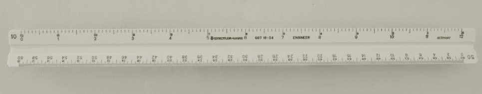
A device called a scale is generally used to make measurements of building plans. Scales physically look like a ruler, but are marked differently. There are two basic types of scales: architect and engineer. Architect scales use common fractions to determine lengths. House plans are generally drawn to a scale of 1/4" = 1', or 1/8" = 1'. This is the same as saying that the scale is 1" = 4', but commercial and industrial buildings are generally too large to be drawn to this scale. If a building is 500 feet in length it would require a minimum of 125 inches to draw the building at a scale of 1" = 4'. For this reason, plans for commercial and industrial building are draw to a much larger scale. An engineer scale would be used when working with a plan of this type. The engineer scale contains scales that work with factors of 10, such as 1" = 10', 1" = 30', and up to 1" = 60'. Scales are generally triangular shaped to permit six different scales on one measuring device, Figure 1-2.
FIGURE 1-2
Reading the Scale
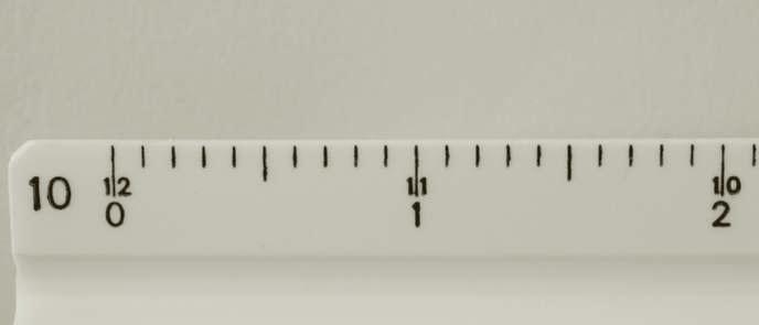
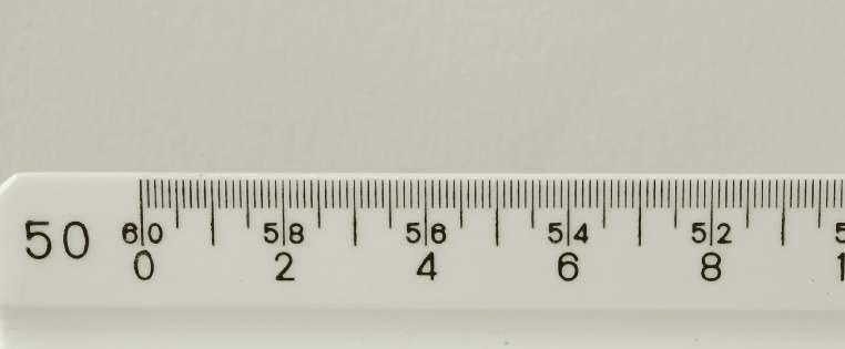
Reading a scale may seem difficult until you understand a few basic principles. A portion of the 1" = 10' scale is shown in Figure 1-3. The scale is divided into 12 one-inch segments like a common ruler, but there are 10 marks between each of the 1 inch divisions. To better understand how to use this scale, mentally add a zero after the numbers shown. The number 1 becomes 10 and the number 2 becomes 20. Since this scale is designed to represent a scale of 1" = 10', the first inch mark would represent 10 feet. There are 10 hash marks between 0 and 1. Each hash mark, therefore, represents a distance of 1 foot. A larger hash mark midway between the inch marks is added for convenience. There are also 10 hash marks between the 1 and 2. Adding a mental zero after the 2 would indicate that it represents a distance of 20 feet. The first hash mark after the 1-inch mark or 10 feet mark would indicate a distance of 11 feet.
Above the 0 is a smaller number 12, and above the 1 is a smaller number 11, and above the 2 is a smaller number 10. These smaller numbers permit the scale to be read from the opposite end. Like the larger numbers, mentally add a zero to each. This scale represents a scale of 1" = 10'. Since it contains a total of 12 inches, it can measure a total length of 120 feet.
Because the composite site plan is drawn to a scale of 1" = 50', the 1" = 50' scale will be discussed next. Like the previous example, to better understand how to use this scale, mentally add a zero after each number. The 2 becomes 20 and the 4 becomes 40. At a length of 1 linear inch the scale represents a distance of 50 feet, Figure 1-4. The scale is divided by larger and smaller hash marks. The space between each of the larger hash marks represents a distance of 10 feet. There are 10 smaller hash marks between each of the larger. Each of the small hash marks represents a distance of 1 foot.
FIGURE 1-3
The 1" = 10' scale.
FIGURE 1-4
The 1" = 50' scale.
The smaller numbers show above the larger numbers permits the scale to be read from the opposite end. The number above the 0 is 60. By mentally adding a zero, 60 becomes 600. This scale can measure a total distance of 600 feet.
Sitework
There may be requirements for several different types of electrical systems to be installed on the site apart from the building itself. The electrician should review the plans and specifications carefully to be aware of all requirements. It is then the responsibility of the electrical contractor/electrician to ensure that these requirements are met and that installations are made at the most advantageous time and in a fashion that will not conflict with sitework being carried out by other trades.
Testing the Site for Grounding Requirements
When determining the site for a building, one of the most important considerations is the system ground. Proper grounding helps protect against transient currents, electrical noise, and lightning strikes. Several methods can be used to test the electrical grounding system. The effectiveness of the grounding system greatly depends on the resistivity of the earth at the location of the system ground. The resistivity of the earth varies greatly throughout the world and even within small areas. Many factors affect the earth’s resistivity such as soil type (clay, shell, sand, etc.), moisture content, electrolyte content (acids, salts, etc.), and temperature.
In theory, the system ground is considered to have a resistance of zero because it is connected to system grounds everywhere, via the neutral conductor, Figure 1-5. In actual practice, however, the
Ser vice panel
Neutral conductors
Neutral bus
Grounding rod
FIGURE 1-5
current carrying capacity of the grounding system can vary greatly from one area to another.
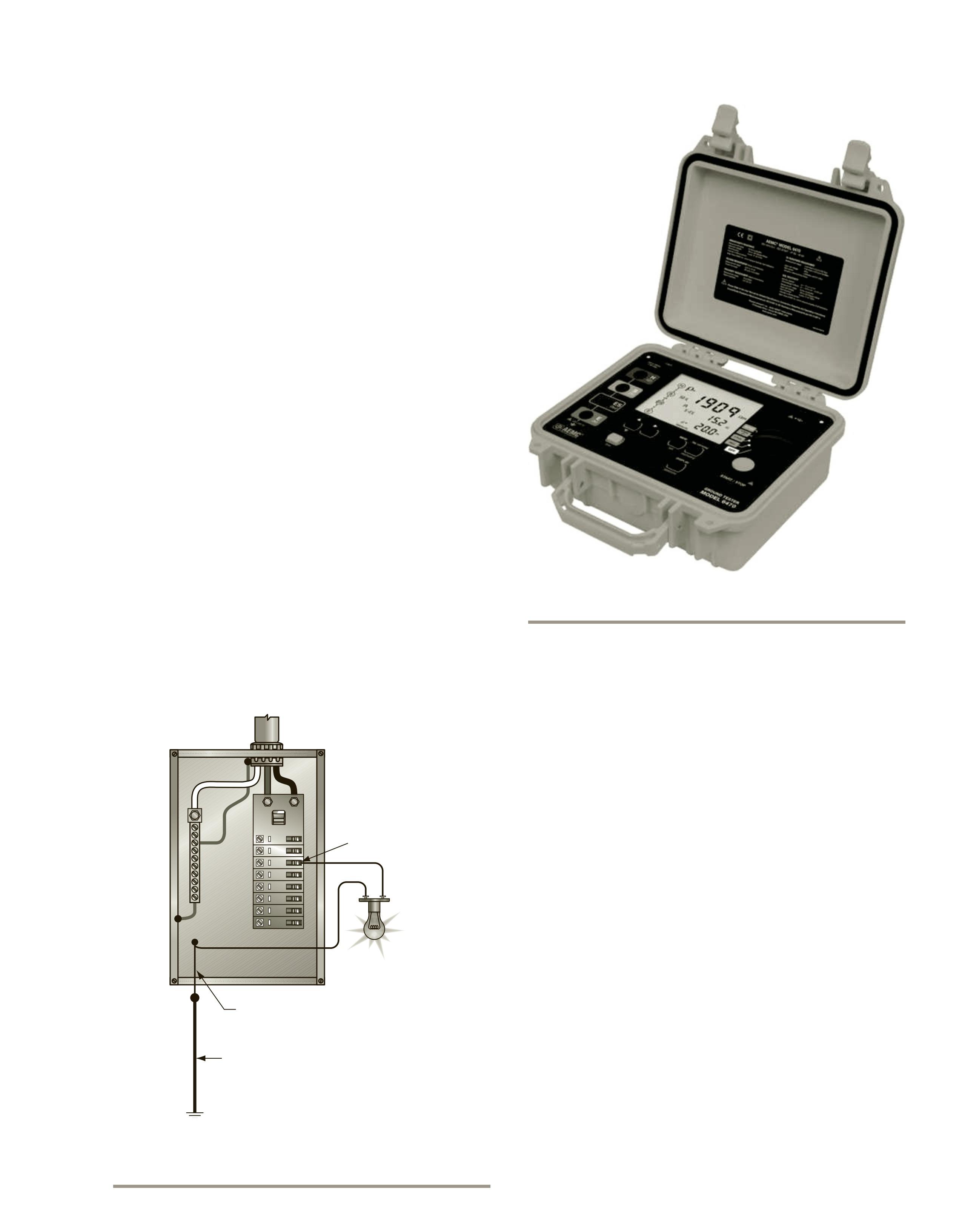
Testing
There are different methods for determining the resistivity of the grounding system. An old method used by electricians for many years is to connect a 100-watt lamp between the ungrounded (hot) conductor and the grounding conductor, Figure 1-6. To perform this test, the grounding conductor must be disconnected from the neutral bus in the panel. The brightness of the lamp gives an indication of the effectiveness of the grounding system. Although this test indicates whether the grounding system works, it does not indicate the actual resistance of the system. To measure the actual resistance of the grounding system requires the use of special equipment such as a ground resistance tester, Figure 1-7. There are three main tests used to measure ground resistance: the Wenner four-point test, the three-point fall-of-potential test, and the clamp-on ground resistance test.
The Wenner Four-Point Method
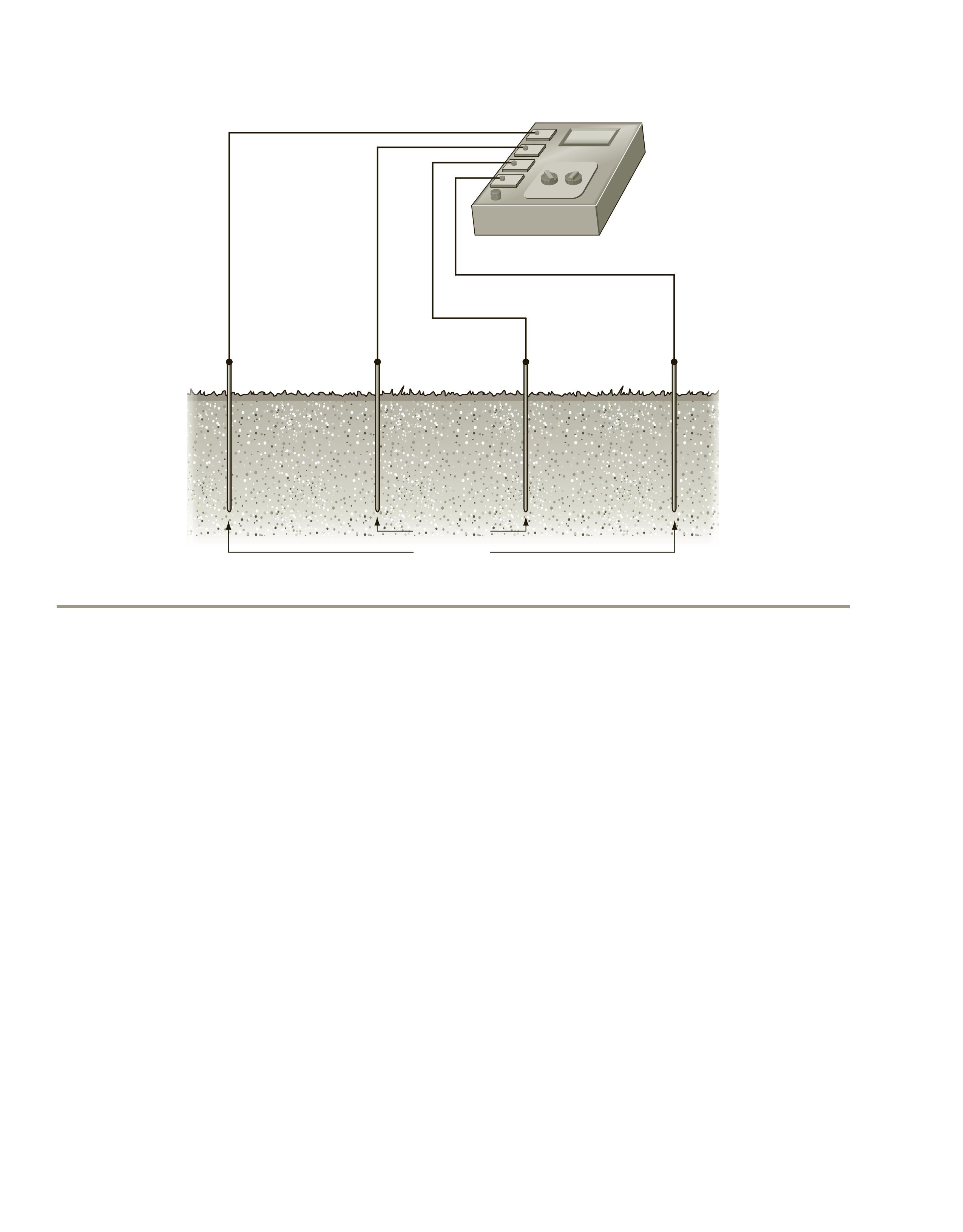
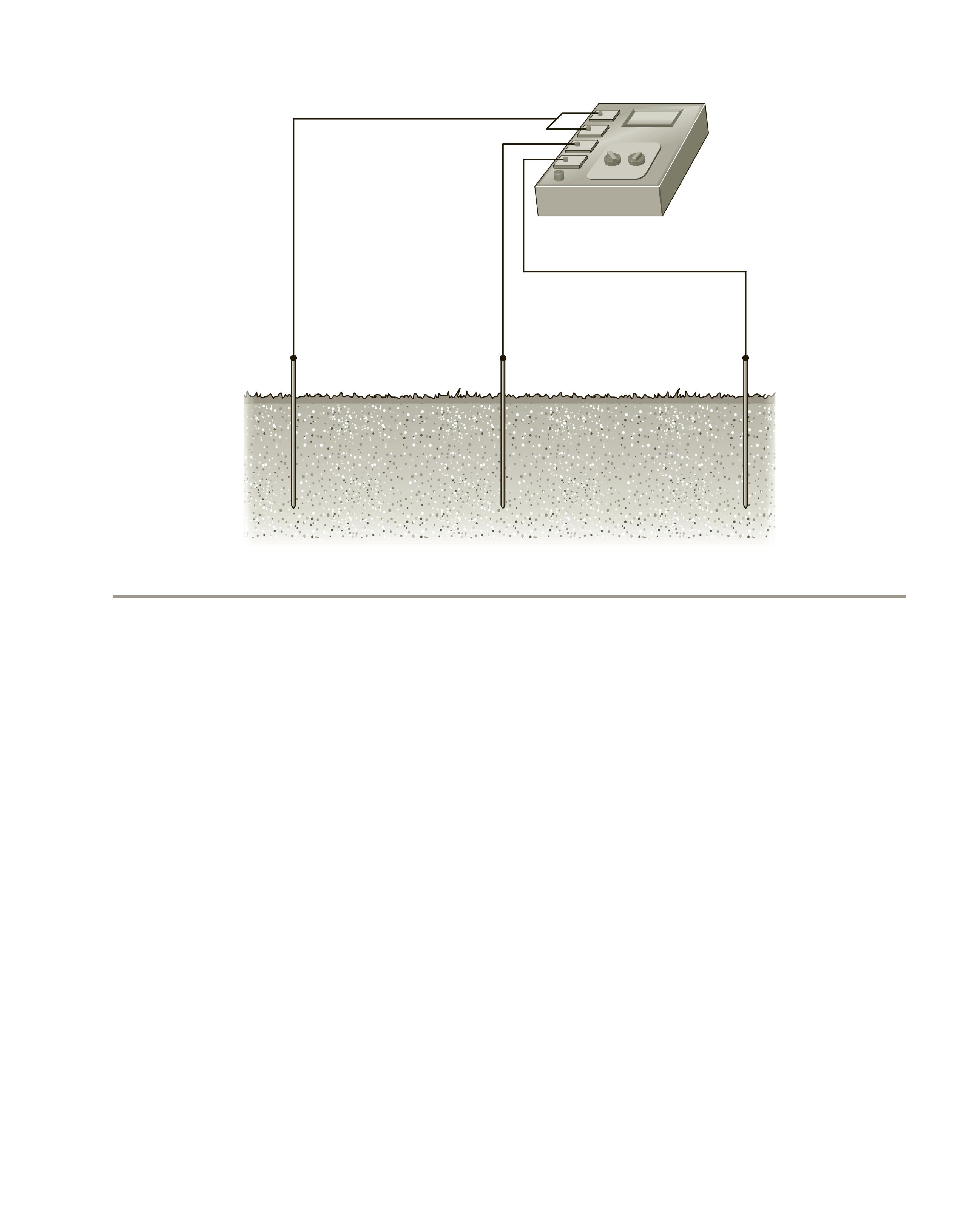
The Wenner four-point test is generally performed before building construction begins. This method
measures the ground resistance over a wide area. The results are used in designing the grounding system to ensure that it performs properly. This test requires the use of a 4-pole ground resistance meter, four metal rods, and conductors. The four rods are driven into the ground in a straight line, with equal space between each rod, Figure 1-8. To perform this test, the ground resistance tester produces a known amount of current between rods C1 and C2, producing a voltage drop across rods P1 and P2. The amount of voltage drop is proportional to the amount of current and ground resistance. Readings are generally taken with probes C1 and C2 spaced 5, 10, 15, 20, 30, 40, 60, 80, and 100 feet apart. If possible, it is recommended to perform the test with the probes spaced 150 feet apart.
The calculated soil resistance is the average of the soil resistance from the surface to a depth equal to the space between the probes. If the probes are set 30 feet apart, for example, each probe will provide an average resistance measurement from the surface to a depth of 30 feet. The tests should not only be made with the probes spaced different distances apart but also with the probes in different directions from a central point. If the site is large enough, it is generally recommended
FIGURE 1-6 A 100-watt lamp is used to test the grounding system.
FIGURE 1-7 Ground resistance tester. Courtesy
to perform the test along at least two sides, generally from one corner to the other. It should be noted that underground structures such as metal water pipes can influence the readings. The best results will be obtained by gathering as much data as possible.
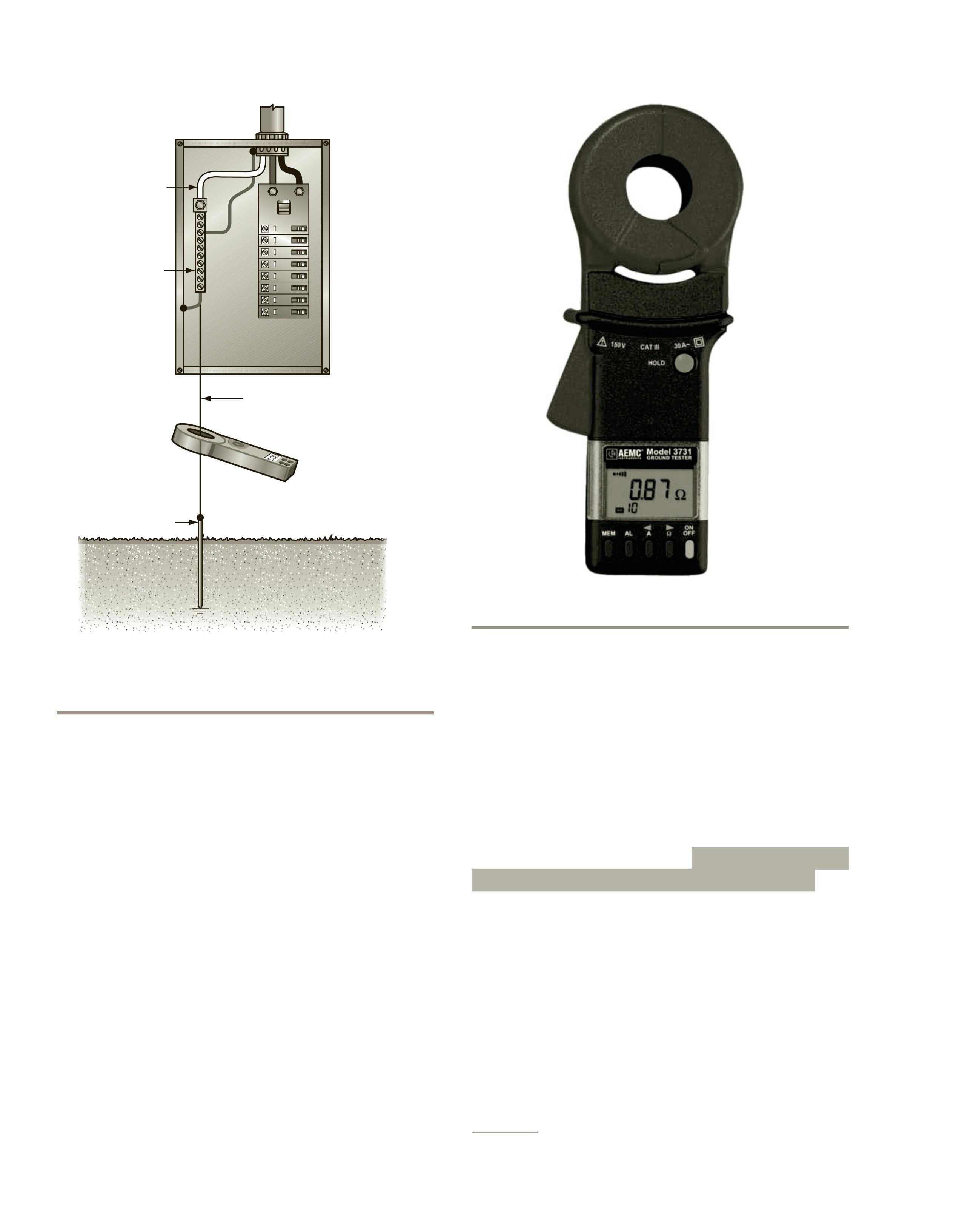
Three-Point Fall-of-Potential Test
The fall-of-potential test requires the use of a ground resistance meter. It is performed after the installation of the grounding system and should be done annually to ensure the quality of the grounding system. Annual testing provides protection against the degradation of the system before damage to equipment and performance problems occur.
In the three-point fall-of-potential test, the three points of ground contact are
1. the system ground (grounding rod) (point A);
2. a current probe placed some distance from the grounding rod (point B); and
3. a voltage probe that is inserted at various distances between the grounding rod and the current probe (C). The voltage probe is placed in a straight line between the grounding rod and the current probe.
Ideally, the current probe (B) should be placed at a distance that is at least 10 times the length of the grounding rod (A), Figure 1-9. If the grounding rod is 8 feet in length, the current probe should be placed at least 80 feet from the grounding rod.
To perform this test, the grounding rod must be disconnected (electrically isolated) from the neutral bus in the service panel. Failure to do so will completely invalidate the test. The meter provides a known amount of current that flows from the current probe and back to the meter through the system grounding rod. The resistance of the earth causes a voltage drop that is measured between the current probe and the voltage probe. The amount of voltage drop is proportional to the amount of current flow and the ground resistance.
FIGURE 1-8 The Wenner four-point test.
FIGURE 1-9 The three-point fall-of-potential test.
Resistance readings should be taken at several locations by moving the voltage probe a distance equal to 10% of the distance between the system grounding rod and the current probe. If performed properly, the three-point ground resistance test is the most accurate method of determining ground resistance.
The Clamp-On Ground Resistance Test
The clamp-on ground resistance test requires the use of a special clamp-on ground resistance meter. This test has several advantages over the three-point fall-of-potential test.
1. The service grounding system does not have to be disconnected and isolated from the neutral bus.
2. There are no probes that have to be driven into the ground or long connecting conductors.
3. The neutral conductor supplied by the utility company ties innumerable grounds together in parallel. The clamp-on ground tester measures the effective resistance of the entire grounding system.
4. Because this test is performed by a clamp-on meter, there are no connections that have to be broken or reconnected, resulting in a safer procedure, Figure 1-10.
The clamp-on ground resistance tester, Figure 1-11, contains two transformers. One transformer induces a small fixed voltage at approximately 2 kHz on the grounding conductor. If a path exists, the voltage will result in a current flow. The path is provided by the grounding system under test, the utility neutral, and the utility grounding system. The second transformer inside the meter senses the amount of current at the unique frequency provided by the first transformer. The amount of current is proportional to the induced voltage and the resistance of the grounding system. The
meter uses the two known electrical quantities to calculate the resistance of the grounding system.
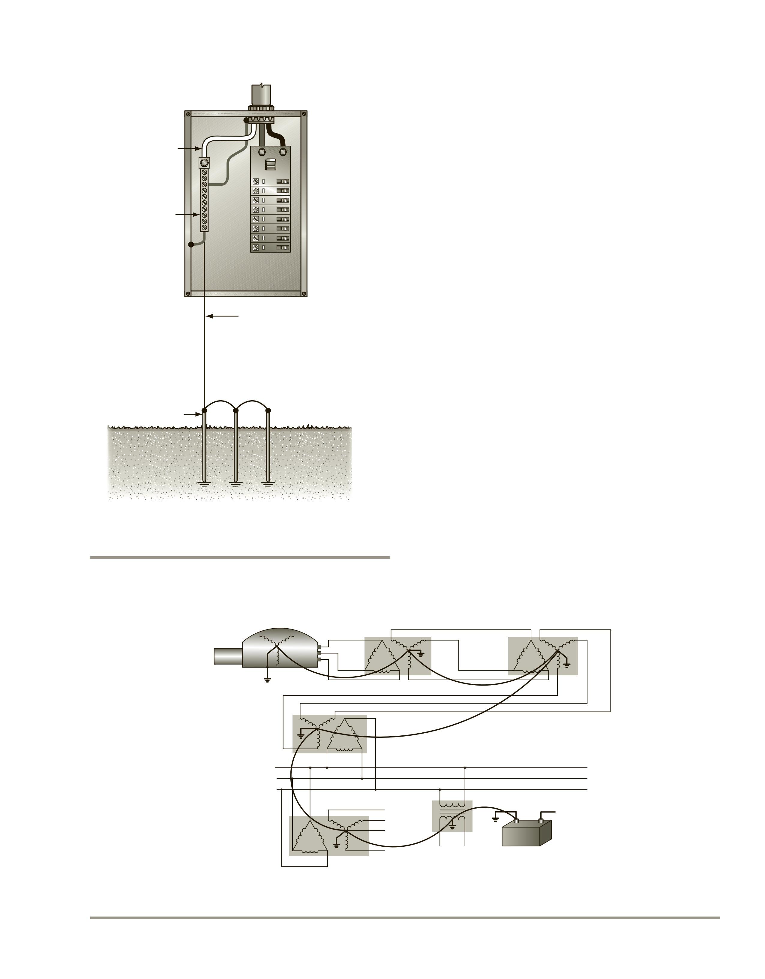
The information gathered from these tests is used to help determine the best grounding method for the electrical installation. In some cases it may be necessary to employ multiple ground rods connected together, Figure 1-12, or other types of grounding electrodes as discussed in NEC 250.50, 250.52, and 250.53.
Grounding and Bonding Considerations
Many technicians and electricians pay little attention to grounding and know only the basic requirements specified by the National Electrical Code. However, grounding is one of the most important parts of any electrical installation. Proper grounding protects circuits and equipment from destruction and
personnel from injury. Grounding is generally thought of as connecting a system to earth via a grounding electrode, as shown in Figure 1-10. In reality, grounding is connecting a circuit to a common point of reference. Almost all grounded systems are connected to earth, which is a common point of reference, but the earth generally does not provide the low-impedance path necessary to protect against ground-fault currents. NEC 250.4(A)(5) states, The earth shall not be considered an effective ground-fault current path.*
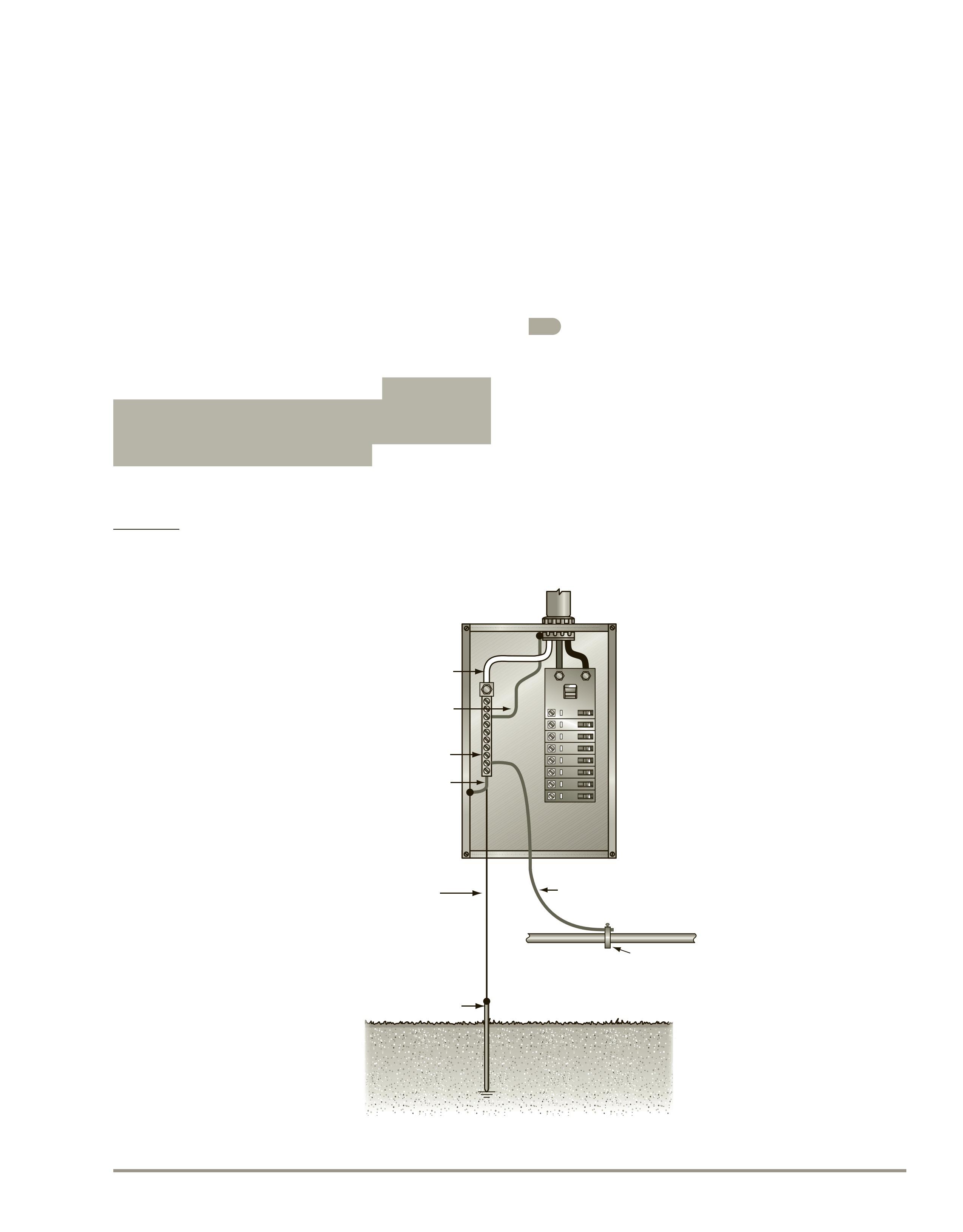
Grounding not only provides a low-impedance path for fault currents, but it also provides a common point of reference for different electrical systems and voltages, Figure 1-13. A low-impedance path exists from the alternator supplying power to the last device connected to the circuit. The alternator has an output of 13.8 kV, which is stepped up to 138 kV for transmission. The voltage is stepped back down to 13.8 kV at a unit substation. The plant substation steps the voltage down to 480 volts to feed the
*Source: NFPA 70-2017
Clamp-on ground tester
Grounding electrode conductor
Grounding rod
Utilit y neutral conductor
Neutral bus
FIGURE 1-10 The clamp-on ground resistance test.
FIGURE 1-11 Ground resistance tester.
Courtesy of AEMC ® Instruments
plant bus system. Other 3-phase and single-phase transformers are powered by the plant bus. A battery backup system is used by an uninterruptable power supply. All of these different power systems and voltages are connected together via grounding conductors. Grounding is also used to protect against lightning, static electricity, and the influence of high frequency. It should be noted, however, that the grounding requirements listed in the National Electrical Code are intended for direct current and 60-hertz AC systems. These requirements may not provide an effective ground for high frequency. Alternating current systems are subject to skin effect, which is the tendency of electrons to move toward the surface of a conductor, Figure 1-14.
The higher the frequency, the greater the skin effect. At a frequency of 10 MHz, a 6 AWG copper conductor may exhibit a resistance of several thousand ohms. High-frequency circuits must be grounded with a conductor that contains a large surface area, such as braided cable or wide copper tape.
Safety
Besides providing a common point of connection for different systems and voltages, grounding plays a large part in the safety of equipment and personal.
FIGURE
Grounding electrode conductor
Grounding rod
Utility neutral conductor Neutral bus
FIGURE 1-12 It is sometimes necessary to connect multiple grounding electrodes together.
When the grounding system is properly installed and maintained, it provides a low-impedance path to ground. A common saying among people in the electrical trades is that current follows the path of least resistance. There is some truth to that idea, but it is not the whole truth. Current will behave in the manner dictated by Ohm’s law. Assume that a 3-phase, 480-volt motor is protected by a 30-ampere circuit breaker. Also assume that the stator windings have an impedance of 20 ohms. If the stator windings are connected in wye, Figure 1-15, each winding will have an applied voltage of 277 volts (480/1.732).
The phase current will be 13.85 A (277/20). Because the stator windings are connected in wye, the line current will be the same as the phase current. Now assume that one of the phase windings develops a shorted winding to ground. If only part of the winding is shorted, the motor may still operate with an increase of current on two of the lines, and the current may not be sufficient to cause the circuit breaker to open, Figure 1-16.
If the case of the motor is not grounded, there is no complete circuit for current flow, which causes the case of the motor to exhibit a voltage of approximately 277 volts to ground. Anyone touching the motor is in danger of electrocution. The resistance of the human body can vary from as low as 500 ohms to as high as 600,000 ohms. Assume that a person touching the motor has a resistance of 1000 ohms to ground. That would produce a current flow of approximately 277 mA, which is about three times the amount necessary to cause death.
If the motor is properly grounded, Figure 1-17, the grounding conductor will provide a very lowimpedance path to ground. The low-impedance
FIGURE 1-14 Alternating current causes electrons to move toward the surface of the conductor. This action is called skin effect.
FIGURE 1-15 A 3-phase motor is connected to 480 volts.
FIGURE 1-16 One-stator windings develop a short to the case of the motor.
Grounding conductor
FIGURE 1-17 A grounding conductor provides a low-impedance path to ground.
grounding conductor forces the motor case to exist at ground potential, and the shock hazard is eliminated. Also, the current path to ground will very likely cause enough current flow for the circuit breaker to open. It should be noted that grounding conductors should be installed in the same conduit as circuit conductors; otherwise, the impedance of the grounding conductor may increase due to inductance.
Bonding
Bonding is used to connect the metal parts of equipment or building structure to the grounding system. The NEC states that Bonding shall be provided where necessary to ensure electrical continuity and the capacity to conduct safely any fault current likely to be imposed.* Article 250 of the NEC lists the requirements and specifications for the bonding of equipment. Bonding jumpers
*Source:
are lengths of wire used to connect the equipment to the grounding system. Some examples of where bonding jumpers are required are around impaired connections such as reducing washers or oversized, concentric, or eccentric knockouts. Metallic boxes, raceways, cable trays, cable sheath, armored cable, metal water pipes, and exposed parts of metal buildings are also required to be bonded, Figure 1-18.
Interpreting the Site Plan
Notations that do not normally appear on a site plan have been added to plan Z1 of the plans located in the back of the text. These notations are aids used to locate specific spots on the plan. The notations are identified by an asterisk followed by a number such as *1, *2, and so on.
Refer to the Composite Site Plan. Note the benchmark located in the southeast quadrant of the plan. This is the point at which the surveyor began
FIGURE 1-18 Bond jumpers are used to connect electrical parts to ground.
NFPA 70-2017
measuring the elevations seen on the plan. Notice that some of the elevation lines have crossing hash marks. The hash marks indicate that that section of the elevation is to be changed. Locate the contour lines for 748 and 749. Parts of these lines have crossing hash marks and parts do not. Only the sections denoted with hash marks are to be changed.
The new elevations are shown with dark heavy lines. These dark heavy lines are shown to connect at some point with the existing contour lines. The elevation of the connecting contour line indicates what the new elevation is intended to be. At position *1, located in the upper southwest quadrant, a heavy dark line connects with the 749 elevation line. The area indicated by the new contour line is to be 749. Locate the new contour line connecting with the 749 contour line at *2. Trace this line to the point where it intersects with the layout of the building. Notice that the entire building is positioned in an area marked by these two new contour lines. This indicates that the building site is to be changed to a uniform 749 ft in preparation for pouring the concrete slab.
The site plan indicates that the industrial building has an elevation of 751.5 ft. This is the elevation of the poured concrete slab. The difference in elevation between the finished slab height and finished ground elevation is the thickness of the concrete slab. In this example the concrete slab will be poured to a thickness of 30 in.
New spot elevations are used to indicate an elevation different from that marked by the plot plan. For example, locate the new contour line at *3. This new contour line connects to the 747 contour line. Now locate the new spot elevation at position *4. The arrow points to the curb inlet drain. The curb inlet drain is located in an area that is indicated to be 747 ft. The new spot elevation, however, shows that the curb inlet drain is to be 0.3 ft (90 mm) lower than the surrounding area.
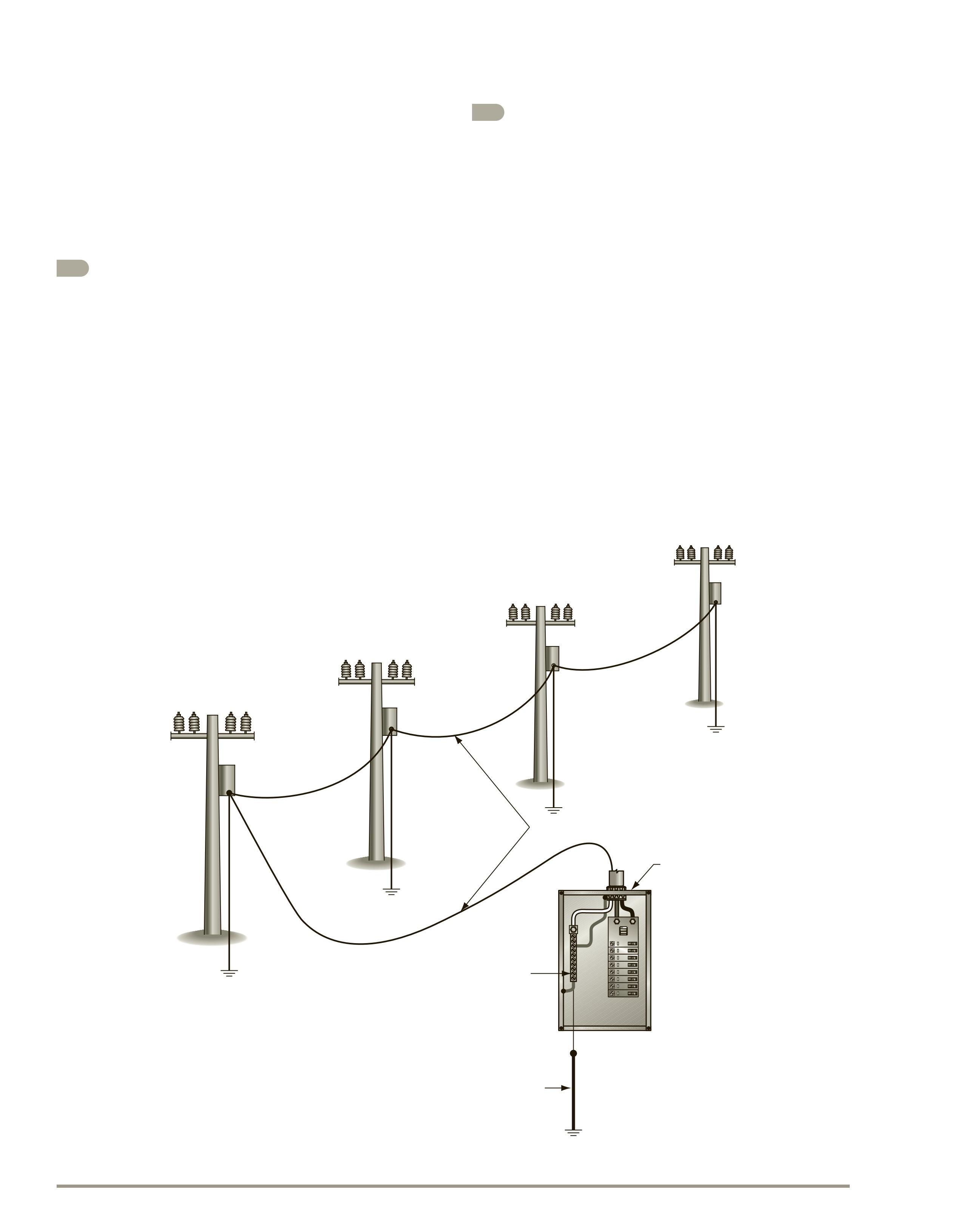
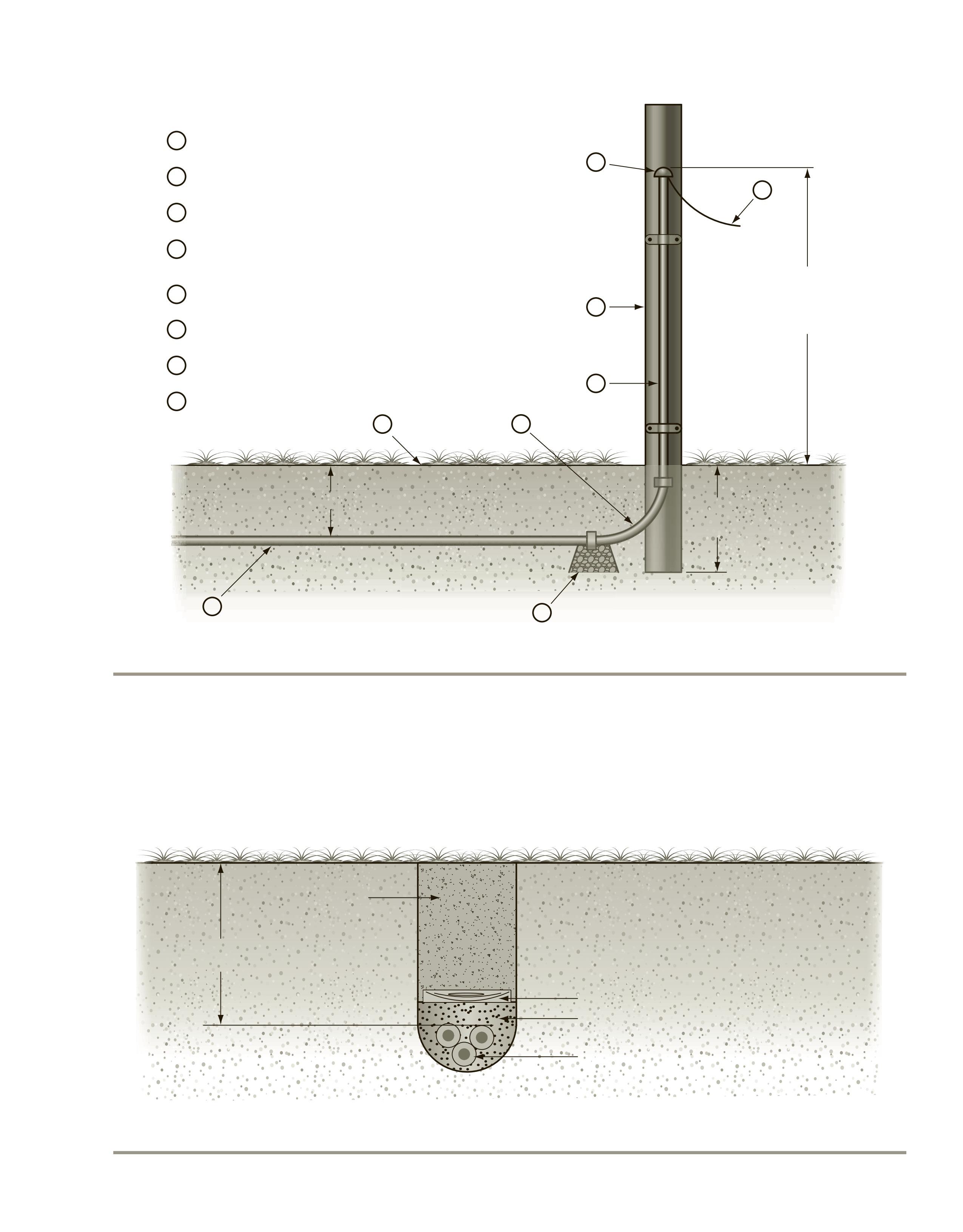
Telephone Service
Telephone service is provided by conduit that runs from the telephone pole. The conduit runs underground at a minimum depth of 18 in. (450 mm) and then is run up the telephone pole for a distance of 8 ft (2.5 m), Figure 1-19. A temporary standard pole cap is installed to protect the equipment from water
until the cables are pulled in. The telephone company later removes this cap and extends the conduit up the pole to the point of connection. The conduit is then sealed with a special telephone fitting or with a compound known as gunk. A long sweep conduit elbow or quarter bend is installed at the base of the pole. At the lowest point of this fitting, a small V-groove is cut or a 3⁄8 in. (9.5 mm) hole is drilled for moisture drainage. This drainage hole is known as a weep hole. A small dry well is then constructed below the weep hole and is filled with rocks. A pull wire (fish wire) is installed in the raceway from the pole to the junction box at the point where it enters the building. In general, 12-gauge galvanized wire is used as the fish wire, but a nylon string will do as well.
Direct Burial Wiring
The electrician may have a choice of several methods of installing underground wiring. The selection of the method to be used depends on the type of materials available and whether provisions are to be made for replacing the conductors. If direct burial cable is used, Figure 1-20, care must be taken to protect the cable from damage. For example, the cable can be installed in the ground to a greater depth than that at which normal digging takes place. Added protection is obtained by placing a treated board over the cable to provide a shield against digging and probing near the cable. The cable should also be surrounded by a layer of sand to prevent any abrasion of the cable by sharp stones and other objects in the soil.
Underground Raceways
Although underground raceways are more expensive to install, they provide many advantages that direct burial installations do not, such as permitting the removal of the original conductors and/or the installation of new conductors with higher current or voltage ratings. Underground raceways are available in a number of different materials, including rigid metal conduit and rigid nonmetallic conduit. Rigid metal conduit can be installed directly in the soil if (300.5 and 300.6 of the National Electrical Code [NEC]):
• ferrous conduits (iron or steel) do not rely solely on enamel for corrosion protection;
Treated pole
Pole cap
Fish wire
Trade size 2 rigid metal conduit, inter mediate metal conduit, or schedule 80 pvc [NEC 300.5(D)(4)]
Long sweep ell
Dr y well
Underground raceway Grade
Minimum 8 ft (2.5 m) above finished grade [NEC 300.5(D)(1)]
1-19 Telephone service installation.
• the conduit is made of a material judged suitable for the condition; and
• the conduit is not placed in an excavation that contains large rocks, paving materials, cinders,
large or sharply angular substances, or corrosive material.
Special precautions should be taken when using nonferrous conduit (aluminum) to prevent the conduit
Treated running board 6 in. (150 mm) of sand
Cable approved for direct burial
1-20 An installation of direct burial cable.
FIGURE
FIGURE
from contacting sodium chloride (salt) mixtures. Concrete mixes often use such mixtures to lower the freezing temperature of the green concrete. The chemical reaction between the aluminum and the salt may cause the concrete to fracture or spall (chip or fragment). When protection is desired or required for the type of raceway used, concrete is poured around the conduit, as shown in Figure 1-21, with at least 2 in. (50 mm) of cover in compliance with NEC Table 300.5.
The use of rigid polyvinyl chloride conduit type PVC is covered in NEC Article 352. These conduits may be used:
• concealed in walls, floors, and ceilings;
• under cinder fill;
• in locations subject to severe corrosive conditions;
• in dry and damp locations;
• exposed where not subject to physical damage; and
• underground.
If the electrical system to be installed operates at a potential higher than 600 volts, the nonmetallic
conduit must be encased in not less than 2 in. (50 mm) of concrete.
NEC Article 344 gives the installation requirements for rigid metal conduit and NEC Article 352 covers rigid polyvinyl chloride conduit type PVC. The minimum requirements for the installation of conduit and cables underground are given in NEC Table 300.5. The general installation requirements are as follows.
For direct burial cables:
• the minimum burial depth is 24 in. (600 mm);
• where necessary, additional protection is to be provided, such as sand, running boards, or sleeves;
• a residential exception permits cable burial to a depth of only 12 in. (300 mm) with GFCI protection; NEC Table 300.5, column 4.
For rigid polyvinyl chloride conduit type PVC:
• the minimum burial depth is 18 in. (450 mm);
• a 12 in. (300 mm) burial depth is permitted if a 2 in. (50 mm) concrete cover is provided over conduit;
6 in. (150 mm) minimum for rigid metal conduit (RMC) 18 in. (450 mm) minimum for other raceways 12 in. (300 mm) with concrete encasement
Concrete encasements are required for certain types of raceways Plastic support permits concrete to flow under and around raceway
Earth
Fill
FIGURE 1-21 Concrete encasement of raceways.
• a 24 in. (600 mm) burial depth is required in areas subjected to heavy vehicular traffic. For rigid conduit:
• the minimum burial depth is 6 in. (150 mm);
• a 24 in. (600 mm) burial depth is required in areas subjected to heavy vehicular traffic.
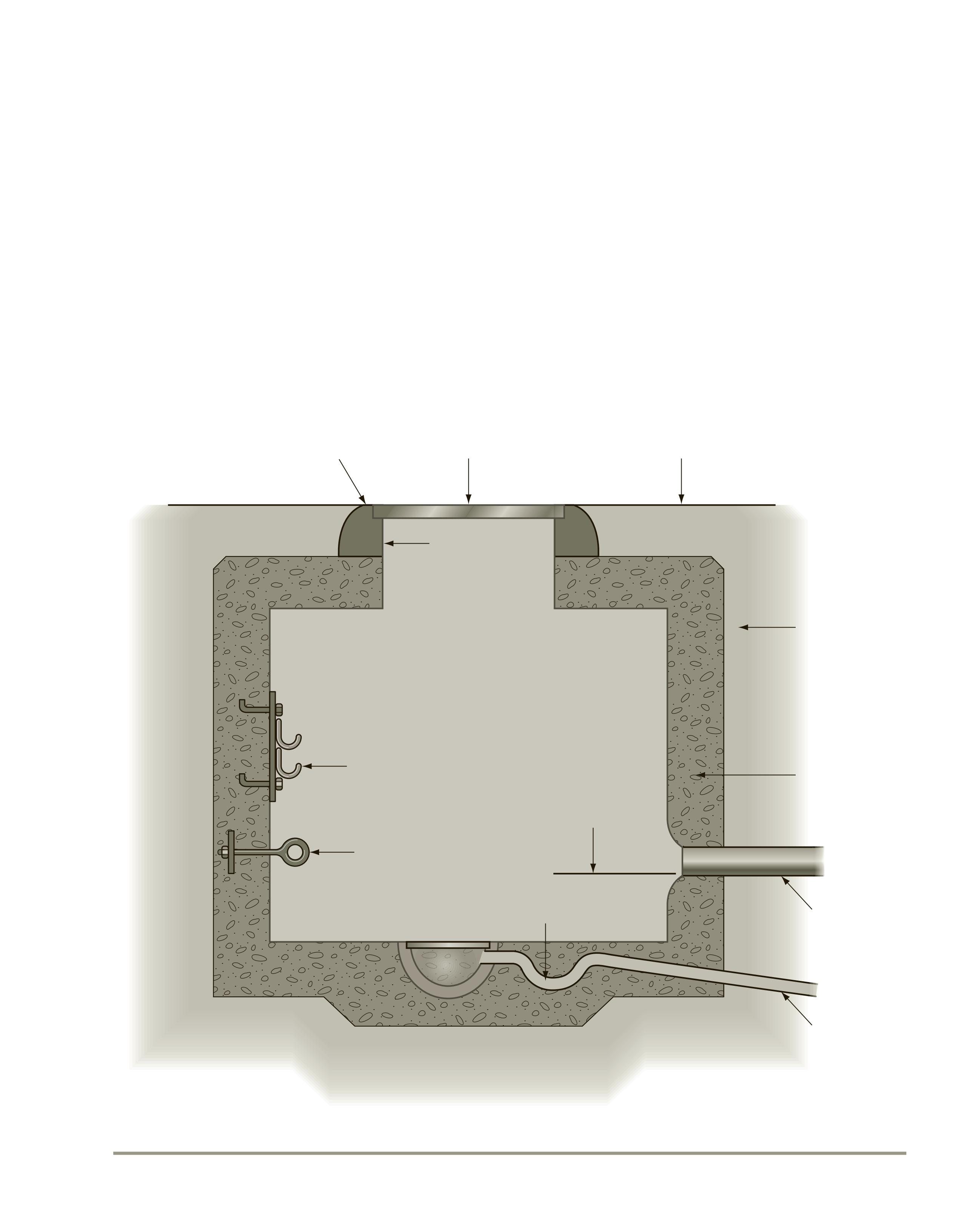
Manholes
Underground raceways terminate in underground manholes similar to the one shown in Figure 1-22. These manholes vary in size depending on the num-
ber and size of raceways and conductors that are to be installed. The drain is an important part of the installation because it removes moisture and allows the manhole to remain relatively dry. If a storm sewer is not available for drainage, the installation of a dry well is an alternate choice.
Lighting Standards
Most types of area lighting standards require the installation of a concrete base, Figure 1-23. The manufacturer of the lighting standard should provide a template for the placement of the anchor bolts. If
Manhole rim Manhole coverGrade elevation
Backfill
May be concrete or brick
Conduit
Drain
Trap
Invert elevation
Pulling ring
Cable rack
Manhole head
SEE NEC ARTICLE 110 PART V FIGURE 1-22 Typical manhole.
the manufacturer fails to provide a template for the placement of anchor bolts, the electrician should supply the general contractor with the template. The conduit installed in the base should be supplied with bushings on the ends to protect the cables. It is important that proper grounding be achieved at each lighting standard. A grounding conductor shall be installed with the supply conductors as the earth cannot be the sole grounding path; see 250.54. This section also permits the installation of supplementary grounding electrodes as shown in Figure 1-23. It is mandatory that all conductive parts, including the grounding electrode, base, bolts, and conduits, be bonded together to achieve comprehensive grounding. See 250.2, 250.134, and 250.54
Metrics (SI) and the NEC
The United States is the last major country in the world not using the metric system as the primary system. We have been very comfortable using English or U.S. customary values, but this is changing. Manufacturers are now showing both English
and metric dimensions in their catalogs. Plans and specifications for governmental new construction and renovation projects have been using SI metric measurements since January 1, 1994. You may not feel comfortable with the metric system, but metric measurements are here to stay. You might just as well get familiar with the metric system.
Some common measurements of length in the English system are shown with their SI metric equivalents in Table 1-2.
The NEC and other National Fire Protection Association (NFPA) Standards are becoming international standards. All measurements in the 2014 NEC are shown with SI metric values first, followed by the inch-pound or English value in parentheses—for example, 600 mm (24 in.). The NEC often refers to English units of measure as inch-pound because they are standard units of measurement in the English system.
In Electrical Wiring—Industrial , ease in understanding is of utmost importance. Therefore, English values are shown first, followed by SI metric values in parentheses—for example, 24 in. (600 mm).
conductor
5/8 in. x 8 ft copper
FIGURE 1-23 Typical concrete base for area lighting standard.
Table 1-2
and metric comparisons.
A soft metric conversion is when the dimensions of a product already designed and manufactured to the English system have their dimensions converted to SI metric dimensions. The product does not change in size.
A hard metric measurement is where a product has been redesigned to standard SI metric dimensions. No conversion from English measurement units is involved. A hard conversion is where an existing product is redesigned into a new size.
In the 2014 edition of the NEC, existing English dimensions did not change. SI metric conversions were made, then rounded off. Please note that when comparing calculations made by both English and metric systems, slight differences will occur as a result of the rounding off of values. These differences are not significant, and calculations for both systems are therefore valid. Where rounding off would create a safety hazard, the metric conversions are mathematically identical. For example, if a dimension is required to be 6 ft, it is shown in the NEC as 1.8 m (6 ft). Note that the 6 ft remains the same, and the metric value of 1.83 m has been rounded off to 1.8 m. This edition of Electrical Wiring—Industrial reflects these rounded-off changes. In this text, the English measurement is shown first—for example, 6 ft (1.8 m).
Trade Sizes
Trade sizes of raceways or conduit refer to the inside diameter of the conduit. A section of ½-in. conduit, for example, would have an inside diameter of ½ in. It is interesting to note that these measurements are not correct.
Raceway sizes have always been an approximation. For example, there has never been a 1⁄2 in. raceway! Measurements taken from the NEC for a few types of raceways are shown in Table 1-3.
Table 1-3
Trade size of raceways vs. actual inside diameter.
Table 1-4
This table shows the metric designator for raceways through trade size 3.
You can readily see that the cross-sectional areas, critical when determining conductor fill, are different. It makes sense to refer to conduit, raceway, and tubing sizes as trade sizes. The NEC in 90.9(C)(1) states that where the actual measured size of a product is not the same as the nominal size, trade size designators shall be used rather than dimensions. Trade practices shall be followed in all cases.* This edition of Electrical Wiring—Industrial uses the term trade size when referring to conduits, raceways, and tubing. For example, instead of 1⁄2 in. electrical metal tubing (EMT), it is referred to as trade size 1⁄2 EMT.
The NEC also uses the term metric designator . A 1⁄ 2 in. EMT is shown as metric designator 16 ( 1⁄ 2 ) . A 1 in. EMT is shown as metric designator 27 (1) . The numbers 16 and 27 are the metric designator values. The ( 1⁄ 2) and (1) are the trade sizes. The metric designator is the raceways’ inside diameter—in rounded-off millimeters (mm). Table 1-4 shows some of the more common sizes of conduit, raceways, and tubing. A complete table is found in the NEC, Table 300.1(C) . Because of possible confusion, this text uses only the term trade size when referring to conduit and raceway sizes.
Table 1-5
This table compares the trade size of a knockout with the actual measurement of the knockout.
*Source: NFPA 70-2017
Conduit knockouts in boxes do not measure up to what we call them. Table 1-5 shows trade size knockouts and their actual measurements.
Outlet boxes and device boxes use their nominal measurement as their trade size. For example, a 4 in. 4 in. 11⁄2 in. does not have an internal cubicinch area of 4 in. 4 in. 11⁄2 in. 5 24 cubic inches. Table 314.16(A) shows this size box as having an area of 21 in.3 This table shows trade sizes in two columns—millimeters and inches.
Table 1-6 provides the detailed dimensions of some typical sizes of outlet and device boxes in both metric and English units.
In practice, a square outlet box is referred to as 4 3 4 3 11⁄2-inch square box, 40 3 40 3 11⁄20 square box, or trade size 4 3 4 3 11⁄2 square box. Similarly, a single-gang device box might be referred to as a 3 3 2 3 3-inch device box, a 30 3 20 3 30-deep device box, or a trade size 3 3 2 3 3 device box. The box type should always follow the trade size numbers. Trade sizes for construction material will not change. A 2 3 4 is really a name, not an actual dimension. A 2 3 4 stud will still be referred to as a 2 3 4 stud. This is its trade size.
In this text, measurements directly related to the NEC are given in both inch-pound and metric units. In many instances, only the inch-pound units are shown. This is particularly true for the examples of raceway calculations, box fill calculations, and load calculations for square foot areas, and on the plans (drawings). To show both English and metric measurements on a plan would certainly be confusing and would really clutter up the plans, making them difficult to read.
Because the NEC rounded off most SI metric conversion values, a calculation using SI metric units results in a different answer when compared
NEC® TablE 1-6
Table 314.16(A) Metal Boxes
*Where no volume allowances are required by 314.16(B)(2) through (B)(5).
Reprinted with permission from NFPA 70®, National Electrical Code®, Copyright © 2016, National Fire Protection Association, Quincy, MA. This reprinted material is not the complete and official position of the NFPA on the referenced subject, which is represented only by the standard in its entirety.
with the same calculation done using English units of measure. For example, load calculations for a residence are based on 3 volt-amperes per square foot or 33 volt-amperes per square meter.
For a 40 ft 3 50 ft dwelling:
3 VA 40 ft 50 ft 6000 volt-amperes
In SI metric units of measure, using the roundedoff values in the NEC:
The difference is small, but nevertheless, there is a difference.
To show calculations in both units throughout this text would be very difficult to understand and would take up too much space. Calculations in either SI metric units or English units are in compliance with 90.9(D). NEC 90.9(C)(3) states that where industrial practice is to express units in inch-pound units, the inclusion of SI units shall not be required. It is interesting to note that the examples in Chapter 9 of the NEC use inch-pound units, not metrics.
Guide to Metric Usage
The metric system is a base-10 or decimal system in that values can be easily multiplied or divided by 10 or powers of 10. The metric system as we know it today is known as the International System of Units (SI) derived from the French term le Système International d’Unités.
In the United States, it is the practice to use a period as the decimal marker and a comma to separate a string of numbers into groups of three for easier reading. In many countries, the comma has been used in lieu of the decimal marker, and spaces are left to separate a string of numbers into groups of three. The SI system, taking something from both, uses the period as the decimal marker and the space to separate a string of numbers into groups of three, starting from the decimal point and counting in either direction. For example, 12345.789 99. An exception to this is when there are four numbers on either side of the decimal point. In this case, the third and fourth numbers from the decimal point are not separated. For example, 2015.1415.
In the metric system, the units increase or decrease in multiples of 10,100,1000, and so on. For instance, one megawatt (1,000,000 watts) is 1000 times greater than one kilowatt (1000 watts).
By assigning a name to a measurement, such as a watt, the name becomes the unit. Adding a prefix
to the unit, such as kilo-, forms the new name kilowatt, meaning 1000 watts. Refer to Table 1-7 for prefixes used in the numerical systems.
Certain prefixes shown in Table 1-7 have a preference in usage. These prefixes are mega-, kilo-, the unit itself, centi-, milli-, micro-, and nano-. Consider that the basic metric unit is a meter (one). Therefore, a kilometer is 1000 meters, a centimeter is 0.01 meter, and a millimeter is 0.001 meter.
The advantage of the SI metric system is that recognizing the meaning of the proper prefix lessens the possibility of confusion.
In this text, when writing numbers, the names are often spelled in full, but when used in calculations, they are abbreviated. For example: m for meter, mm for millimeter, in. for inch, and ft for foot. It is interesting to note that the abbreviation for inch is followed by a period (12 in.), but the abbreviation for foot is not followed by a period (6 ft). Why? Because ft. is the abbreviation for fort.
Summary
As time passes, there is no doubt that metrics will be commonly used in this country. In the meantime, we need to take it slow and easy. The transition will take time. Table 1-8 shows useful conversion factors for converting English units to metric units.
system prefixes.
Table 1-7