Piping Engineering Karan Sotoodeh
Visit to download the full and correct content document: https://ebookmass.com/product/piping-engineering-karan-sotoodeh/
More products digital (pdf, epub, mobi) instant download maybe you interests ...
Cryogenic Valves for Liquefied Natural Gas Plants Karan Sotoodeh
https://ebookmass.com/product/cryogenic-valves-for-liquefiednatural-gas-plants-karan-sotoodeh/
Industrial Valves: Calculations for Design, Manufacturing, Operation, and Safety Decisions Karan Sotoodeh
https://ebookmass.com/product/industrial-valves-calculations-fordesign-manufacturing-operation-and-safety-decisions-karansotoodeh/
Subsea Valves and Actuators for the Oil and Gas Industry Karan Sotoodeh
https://ebookmass.com/product/subsea-valves-and-actuators-forthe-oil-and-gas-industry-karan-sotoodeh/
Case Studies of Material Corrosion Prevention for Oil and Gas Valves Karan Sotoodeh
https://ebookmass.com/product/case-studies-of-material-corrosionprevention-for-oil-and-gas-valves-karan-sotoodeh/
Case Studies of Material Corrosion Prevention for Oil and Gas Valves 1st Edition Karan Sotoodeh
https://ebookmass.com/product/case-studies-of-material-corrosionprevention-for-oil-and-gas-valves-1st-edition-karan-sotoodeh/
Estimator’s Piping Man-Hour Manual (Estimator’s ManHour Library) – Ebook PDF Version
https://ebookmass.com/product/estimators-piping-man-hour-manualestimators-man-hour-library-ebook-pdf-version/
Engineering Hydrology Rajesh Srivastava
https://ebookmass.com/product/engineering-hydrology-rajeshsrivastava/
Engineering Mathematics I T. Veerarajan
https://ebookmass.com/product/engineering-mathematics-i-tveerarajan/
Engineering Fundamentals: An Introduction to Engineering, SI Edition Saeed Moaveni
https://ebookmass.com/product/engineering-fundamentals-anintroduction-to-engineering-si-edition-saeed-moaveni/
Piping Engineering
Piping Engineering
Preventing Fugitive Emission in the Oil and Gas Industry
Karan Sotoodeh Hovik
Norway
This edition first published 2023 © 2023 John Wiley & Sons, Inc.
All rights reserved. No part of this publication may be reproduced, stored in a retrieval system, or transmitted, in any form or by any means, electronic, mechanical, photocopying, recording or otherwise, except as permitted by law. Advice on how to obtain permission to reuse material from this title is available at http://www.wiley.com/go/permissions.
The right of Karan Sotoodeh to be identified as the author of this work has been asserted in accordance with law.
Registered Offices
John Wiley & Sons, Inc., 111 River Street, Hoboken, NJ 07030, USA
John Wiley & Sons Ltd, The Atrium, Southern Gate, Chichester, West Sussex, PO19 8SQ, UK
Editorial Office
111 River Street, Hoboken, NJ 07030, USA
For details of our global editorial offices, customer services, and more information about Wiley products visit us at www.wiley.com.
Wiley also publishes its books in a variety of electronic formats and by print-on-demand. Some content that appears in standard print versions of this book may not be available in other formats.
Limit of Liability/Disclaimer of Warranty
In view of ongoing research, equipment modifications, changes in governmental regulations, and the constant flow of information relating to the use of experimental reagents, equipment, and devices, the reader is urged to review and evaluate the information provided in the package insert or instructions for each chemical, piece of equipment, reagent, or device for, among other things, any changes in the instructions or indication of usage and for added warnings and precautions. While the publisher and authors have used their best efforts in preparing this work, they make no representations or warranties with respect to the accuracy or completeness of the contents of this work and specifically disclaim all warranties, including without limitation any implied warranties of merchantability or fitness for a particular purpose. No warranty may be created or extended by sales representatives, written sales materials or promotional statements for this work. The fact that an organization, website, or product is referred to in this work as a citation and/or potential source of further information does not mean that the publisher and authors endorse the information or services the organization, website, or product may provide or recommendations it may make. This work is sold with the understanding that the publisher is not engaged in rendering professional services. The advice and strategies contained herein may not be suitable for your situation. You should consult with a specialist where appropriate. Further, readers should be aware that websites listed in this work may have changed or disappeared between when this work was written and when it is read. Neither the publisher nor authors shall be liable for any loss of profit or any other commercial damages, including but not limited to special, incidental, consequential, or other damages.
A catalogue record for this book is available from the Library of Congress
Hardback ISBN: 9781119852032; ePub ISBN: 9781119852056; ePDF ISBN: 9781119852049; oBook ISBN: 9781119852063
Cover image: © Shazrul Edwan/Shutterstock
Cover design by Wiley
Set in 9.5/12.5pt STIXTwoText by Integra Software Services Pvt. Ltd, Pondicherry, India
Contents
Author Biography ix
1 An Introduction to Fugitive Emission, Piping Engineering, and LDAR 1
1.1 Introduction to Fugitive Emission 1
1.2 Introduction to Piping Engineering 5
1.3 Causes of Piping Failure and Leakage 8
1.4 Leak Detection and Repair (LDAR) 13
1.4.1 Composite Repair 14
1.4.2 Mechanical Clamp Repair 14
1.4.3 Welded Leak Box Repair 15
1.4.4 External Weld Overlay 16
1.4.5 Sleeve Repair 17
1.5 Questions and Answers 18 Further Readings 21
2 Piping Pressure Design to Prevent Leakage and Emission 23
2.1 Introduction to Piping Design 23
2.2 Piping and Pipeline Wall Thickness Calculation 23
2.2.1 Piping Wall Thickness Calculation as per ASME B31.3 23
2.2.2 Pipeline Wall Thickness Calculation 32
2.3 Pipe Fittings Wall Thickness/Pressure Rating 51
2.4 Flange Pressure Rating and Thickness Selection 59
2.5 Questions and Answers 70 Further Readings 84
3 Piping Stress Analysis to Prevent Operational Failure 87
3.1 Introduction to Piping Stress Analysis 87
3.2 Principal Piping Stresses 87
3.3 Sustained Loads 96
3.4 Occasional Loads 106
3.4.1 Earthquake and Blast Load 106
3.4.2 Wind Load 109
3.5 Displacement Stress 111
3.5.1 Stress Intensification Factor (SIF) 127
3.6 Piping Reaction Forces 133
3.6.1 Pressure Safety/Relief Valve Reaction Force 133
3.6.2 Slug Flow Reaction Force 138
3.6.3 Water Hammering Load Calculation 143
3.7 Conclusion 145
3.8 Questions and Answers 146
Further Readings 153
4 Piping Flange Joints 155
4.1 Introduction 155
4.2 Flanges 157
4.2.1 Flange Standards 157
4.2.2 Flange Types 162
4.2.3 Flange Faces 175
4.2.4 Flange Surface (Face) Finish 184
4.2.5 Flange Identification 185
4.2.6 Flange Installation 185
4.3 Gaskets 190
4.3.1 Nonmetallic Flat Gaskets 191
4.3.2 Semimetallic Gaskets 192
4.3.3 Metallic Gaskets 196
4.4 Bolting (Bolts and Nuts) 197
4.4.1 Bolt Tightening 204
4.5 Mechanical Joints (Hubs and Clamps) 210
4.6 Compact Flanges 212
4.7 Questions and Answers 216 Appendix A 220
Further Readings 223
5 Piping Flange Joint Calculations 227
5.1 Introduction 227
5.2 Bolt Length Determination and Calculation 228
5.2.1 Long Bolt Length Calculation for Wafer Body Valves 236
5.2.2 Long Bolt Length Calculation for Flanges with Line Blanks 239
5.3 Flange Leakage Analysis 245
5.3.1 Bolting Characteristics 247
5.3.2 Gasket Behavior 253
5.3.3 Combination of Bolt Loads and Gasket Reaction 254
5.3.4 Flange Loading 262
5.3.5 Pressure Equivalent Method 269
5.4 Questions and Answers 270 Appendix A 275
Further Readings 277
6 Piping Material Selection and Corrosion Prevention 279
6.1 Introduction 279
6.2 Onshore Pipeline 281
6.2.1 Onshore Pipeline Material Selection 281
6.2.2 External Corrosion 282
6.2.3 Pipeline External Corrosion Protection 284
6.2.4
Pipeline Internal Corrosion Types and Mitigation 287
6.3 Onshore Piping 301
6.3.1 Onshore Piping Material Selection 301
6.3.2 Onshore Piping Corrosion Types 315
6.4 Offshore Piping 317
6.4.1 Offshore Piping Material Selection 317
6.4.2 Offshore Piping Corrosion Study 320
6.5 Questions and Answers 322 Further Readings 327
7 Piping Component Selection and Identification 329
7.1 Introduction and Overview 329
7.2 Pipe 329
7.3 Pipe Fittings 331
7.3.1 Fittings for Piping Route Change 331
7.3.2 Fittings for Pipe Size Change 336
7.3.3 Fittings for Branching 341
7.3.4 Fittings for Pipe Termination or Blinding 352
7.4 Questions and Answers 356 Further Readings 361
8 Piping Fabrication, Inspection, and Testing 363
8.1 Introduction and Overview 363
8.2 Fabrication, Assembly, and Erection 363
8.2.1 Welding 367
8.3 Inspection 378
8.3.1 Introduction 378
8.3.2 Welding Inspection 379
8.4 Piping Pressure Test 385
8.4.1 Test Media 386
8.4.2 Test Preparation 387
8.4.3 Test Implementation 387
8.5 Questions and Answers 389 Further Readings 393
Index 395
Author Biography
Karan Sotoodeh, an Iranian author and engineer, previously worked for Baker Hughes as a senior/lead valve and actuator engineer in the subsea oil and gas industry. He earned a doctor of philosophy in safety and reliability in mechanical engineering from the University of Stavanger in 2021. Karan Sotoodeh has nearly 16 years of experience in the oil and gas industry, mainly with valves, piping, actuators, and material engineering. He has written eight books about piping, valves, actuators, corrosion, and material selection and more than 30 papers in peer-reviewed journals. He has also been selected in international conferences in USA, Germany, and China to lecture on valves, actuators, and piping. Karan Sotoodeh has worked with many valve suppliers in Europe in countries such as UK, Italy, France, Germany, and Norway. He loves traveling, running, swimming, and spending time in nature.
1
An Introduction to Fugitive Emission, Piping Engineering, and LDAR
1.1 Introduction to Fugitive Emission
Fugitive emission is defined as the unintentional and undesirable emission, leakage, or discharge of gases or vapors from pressure-containing equipment or facilities, and from components inside industrial plants, such as valves, piping flanges, pumps, storage tanks, compressors, etc. Fugitive emission is also known as leak or leakage. The term “fugitive” is used because these emissions are not taken into account and calculated during the design of the equipment and components.
Volatile organic compounds (VOCs) and hazardous air pollutants (HAPs) are considered the main fugitive emission compounds. HAPs, also referred to as toxic air pollutants, are those that can cause serious health problems such as cancer. The Environmental Protection Agency (EPA) has detected 187 types of HAPs, such as lead, ozone, nitrogen dioxide, etc. VOCs are organic compounds or chemicals that have high vapor pressure at ordinary room temperature and low water stability. Many VOCs are synthetic chemicals used in industry. VOCs are typically emitted as gasses from solids or liquids. Methane CH 4 () is a kind of VOC. VOCs and HAPs are categorized as gases and compounds that are harmful to the atmosphere. The leakage of oxygen or nitrogen from piping and valves is not considered a fugitive emission, since oxygen and nitrogen already exist in the atmosphere and do not cause any environment pollution.
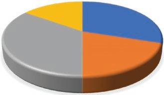
Fugitive emission typically occurs in different industries such as oil and gas, chemical, automotive, etc., as per Figure 1.1. The concentration of this book is on fugitive emission from oil, gas, and chemical plants, such as refineries and petrochemical plants, which are responsible for almost half of total fugitive emission. In addition to fugitive emission associated with vapors and gases, any other type of emission, such as liquid hydrocarbon (oil), hydraulic oil, etc., that is harmful to the environment is addressed in this book.
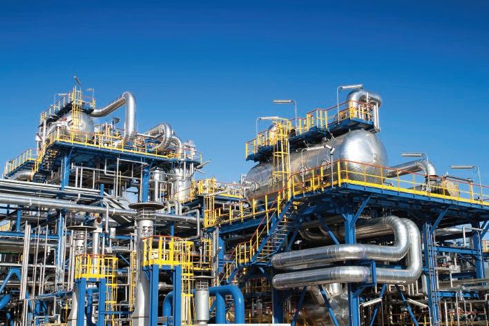
Figure 1.2 illustrates an oil and gas refinery, including piping, structures, and facilities—and fugitive emission. All of the piping and connections, such as flanges, could be points of leakage and emission to the environment. A flange is a ring-shaped, bulk piping component that is used to join two pieces of pipe together or connect piping to equipment in general. Flanges are typically welded to the connected pipe, but may also be threaded. Two flanges are connected with bolting (bolts and nuts), and a gasket is
Piping Engineering: Preventing Fugitive Emission in the Oil and Gas Industry, First Edition. Karan Sotoodeh.
© 2023 John Wiley & Sons, Inc. Published 2023 by John Wiley & Sons, Inc.
placed between them for sealing. Chapters 4 and 5 provide comprehensive information about flange joints, and present calculations for leakage analysis and prevention.
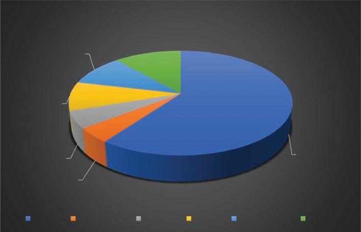
The EPA is an independent, executive agency of the US federal government involved in environmental protection issues. The main aims of the EPA are to protect human and environment health, improve the quality of the air and water, prevent pollution, promote energy usage efficiency, etc. In 1995, the EPA performed research to evaluate the contribution of each component or facility in oil and gas refineries to fugitive emission. The result of this research is provided in the chart illustrated in Figure 1.3. Industrial valves make up 60% of fugitive emission to the environment; thus, they are known as the most critical components when it comes to fugitive emission in the oil and gas industry. Fugitive emission from valves is discussed and reviewed by the author in a separate book named Prevention of Valve Fugitive Emissions in Oil and Gas Industry. Flanges as an important piping connection are responsible for 5.3% of the fugitive emission into the environment. Yet leakage from piping is not limited to flange connections; internal fluid can be leaked from each piping component such as the pipe
A: Chemical 30%
B. Oil and Gas 20%
C. Automative 35%
D. Others 15%
Figure 1.1 Fugitive emission percentage from different industry sectors.
Figure 1.2 Fugitive emission from a refinery. (Courtesy: Shutterstock).
itself, and fittings and pipe joints such as threads and welds. Pipe fittings are defined as piping components that are used to change the size, direction, or routing of the piping, to make a branch from the piping or to blind the end of a pipe. The main aim of this book is to provide solutions in connection to the design and selection, manufacturing, fabrication, installation, inspection, and testing of piping components and their connections to prevent leakage and fugitive emission.
The important fact about connectors, such as flanges, that are used for piping connections is that the average number of flange connectors is higher than that of other sources of emission such as pumps, valves, drains or open-end lines, compressors, and pressure relief valves. Table 1.1 compares the range and average quantities of fugitive-emission–producing components and equipment in a typical refinery or petrochemical plant.
The negative impact and consequences of fugitive emission are significant, and include environmental pollution and damage and loss of production, and fines are levied on companies that produce a high amount of fugitive emission. In 2003, Chevron had to
Table 1.1 Equipment and component quantities in a typical refinery or chemical plant as per EPA.
A: Valves, 60.0%
B. Relief valves, 4.5%
C. Flanges, 5.3%
D. Drains, 8.9%
E: Compressors, 9.8%
F. Pumps, 11.5%
A: Valves B. Relief valves C. Flanges D. Drains E: Compressors F. Pumps
Figure 1.3 Fugitive emission from different components in oil and gas refineries.
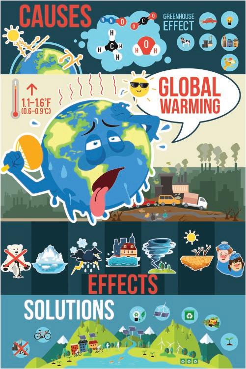
pay 3.5 million USD for fugitive emissions from its refineries. It is important to bear in mind that regulatory agencies are growing less and less tolerant of fugitive emissions. The greenhouse effect and global warming are well known as negative impacts of fugitive emission on the environment. Global warming is the gradual heating of the earth’s surface, oceans, and atmosphere caused by air pollutants such as methane and carbon dioxide and the greenhouse effect. The greenhouse effect is a natural process that warms the earth’s surface. When the sun’s energy reaches the earth’s atmosphere, some of it is reflected back to space and the rest is absorbed and re-radiated by greenhouse gases. Global warming has many negative impacts on the environment, such as melting the glaciers, increasing the incidence of draught, fire, hurricanes and rain storms, causing the rise of seawater, etc. These consequences are illustrated in Figure 1.4.
In summary, fugitive emission is a hazardous phenomenon that leads to atmospheric pollution and economic loss for oil and gas plants. End users, engineers, and managers of oil and gas plants have many reasons to implement fugitive emission reduction; these include ensuring the safety of the people who work in the plants and those who live nearby; avoiding fines by complying with the rules and regulations,
Figure 1.4 Effects of global warming. (Courtesy: Shutterstock).
including those that are strict about air pollution; optimizing the plant’s energy production and maximizing the plant’s safety and reliability.
1.2 Introduction to Piping Engineering
Piping engineering is a specialized discipline of mechanical engineering that involves the design and analysis of piping and the layout of piping and equipment in refineries, petrochemical plants, and other production units in the oil and gas industry. Piping or a piping system is defined as an assembly of piping components, such as pipes, fitting, and valves, used to transport and distribute process fluid between different locations. A pipe is a hollow cylinder usually with a circular cross-section used to convey substances that can flow, such as liquids, gases, powders, and solids. In fact, pipes and piping systems are like veins and arteries in oil and gas plants that transport the fluid. Piping is exposed to a combination of the pressure, temperature, load, and flow of the fluid. Additionally, piping systems are subject to corrosion and erosion, mainly due to internal erosive and corrosive fluid service, and external corrosion in the offshore environment. Some fluid services are toxic, like those that contain a considerable amount of hydrogen sulfide HS 2 () . Leakage of hydrogen sulfide, even in relatively low concentrations such as 100 parts per million (ppm), can kill a human. All of the above-mentioned parameters and concerns call for proper piping design and selection, fabrication and assembly, and inspection and testing to prevent leakage and ensure trouble-free operation for the long design life of a plant.
The function of piping engineering is to apply the knowledge and techniques of material and mechanical engineering, such as stress analysis, and the skills of piping layout in order to convert the process documents, such as a piping & instrument diagram (P&ID) and process flow diagram (PFD), into piping drawings and data from which the piping components can then be purchased, assembled, and tested. In short, piping engineering activities in oil and gas projects are divided into piping layout/design engineering, piping stress and analysis engineering, and piping material engineering. The main tasks involved in piping layout/design engineering are to generate a plot plan and equipment layout and a three-dimensional (3D) model of the piping and equipment. The main tasks of piping stress analysis are to define the piping stress design basis and philosophy, perform piping stress calculations, and produce an analysis report. The main tasks involved in piping material engineering are to define the piping material in cooperation with the process department, perform a corrosion study, prepare the piping specifications, define the required piping components for the purchasing department by preparing material take-off and material requisition, and produce data sheets for special piping components. Special piping components are those components that are not defined in any piping engineering standard, e.g., strainers installed before pumps or compressors to collect the particles in the fluid.
A PFD is a diagram commonly used in the oil and gas industry. It is generated by the process department to show the main process, including the main piping and equipment. A PFD shows the process of the oil, gas, and water treatment in oil field developments. PFDs in refineries and petrochemical plants illustrate how the feed fluid service that enters the plant is converted to the final product. Figure 1.5 illustrates a PFD showing the gas input to a compressor station and a knockout drum installed after the compressor to separate the liquids from the compressed gas generated in the compressor.
A P&ID is a diagram that show the process, including the interconnection of process equipment and the instrumentation used to control the process. P&IDs are more detailed compared to PFDs.
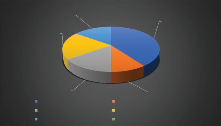
Piping engineering, procurement, and construction are common activities in a typical oil and gas plant. Piping engineering, including detail design, accounts for 25% of total engineering personnel hours to design the whole plant, as per Figure 1.6.
Figure 1.5 Pressure flow diagram (PFD) sample.
Figure 1.6 Typical engineering design personnel man-hours.
As an example, the cost of purchasing piping components, including pipe, fitting, flanges, bolts, gaskets, etc., is around 15% of the overall material cost. As shown in Figure 1.7, the cost of piping components in oil and gas projects is second only to the cost of major equipment.
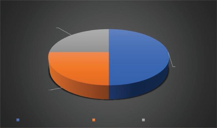
The labor cost of piping construction is the highest compared to the installation of other components such as instruments, electrical components, and mechanical facilities. Refer to Figure 1.8; piping field labor cost makes up 40% of the total construction cost of the plant.
E: Structure, building and foundation,
A: Piping
C. Electrical
E: Structure, building and foundation
B. Instruments
D. Major Equipment
Figure 1.7 Typical costs of equipment and components percentages.
E: Structure, building and foundation, 15.0%
A: Piping
C. Electrical
E: Structure, building and foundation
Figure 1.8 Typical field labor cost percentages.
B. Instruments
D. Major Equipment
A: Piping, 40.0%
B. Instruments, 10.0%
C. Electrical,15.0%
D. Major Equipment, 20.0%
15.0%
A: Piping, 40.0%
B. Instruments, 10.0%
C. Electrical, 15.0%
D. Major Equipment, 20.0%
1.3 Causes of Piping Failure and Leakage
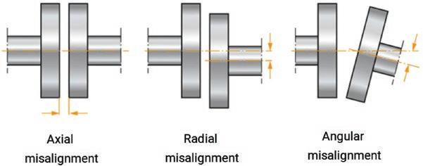
Piping is jointed together through different approaches, such as threaded, welded, and flange connections. A flange is a component used for connecting pipes, valves, pumps, and other equipment together to form a piping system. It provides easy access for cleaning, inspection, or modification of the piping. Flanges are usually welded or screwed to the pipe. Flanged joints are made by bolting two flanges together with a gasket between them to provide a seal. A variety of factors could result in piping system failure and leakage, such as poor material selection; material corrosion; improper piping component design and selection; poor machining or corrosion of the flange face; poor gasket selection; and poor fabrication, installation, and alignment of components such as the flange during installation (see Figures 1.9 and 1.10).
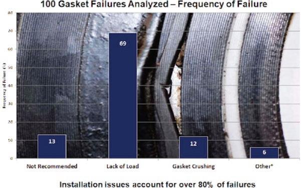
A study found that 80% of gasket failures in piping systems are associated with installation issues, such as gasket misalignment and lack of applied loads on the gasket from the bolting on the flange connections (see Figure 1.11). In fact, three parameters are required to maintain gasket sealing successfully: the first is resilience, such that the gasket sits on and fills the space between the flange mating surfaces and their irregularities. The second is sufficient toughness to resist loads such as blowout and extrusion. The last important factor is sufficient force from the bolting and flange
Figure 1.9 Types of flange misalignment.
Figure 1.10 Flange misalignment close to a pump. (Courtesy: Shutterstock).
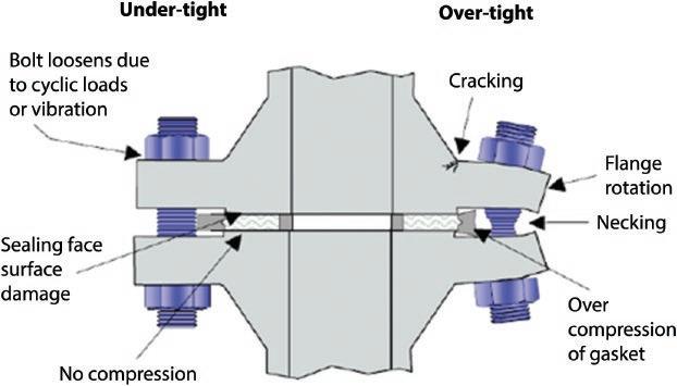
1.3 Causes of Piping Failure and Leakage 9 joints to deform the gasket in order to provide sealing. Lack of bolt load causes insufficient flange pressure to compress the gasket and provide effective sealing, while excessive bolt and flange load can damage the flange and crush the gasket. As indicated in Figure 1.11, 69% of gasket failures are caused by lack of load and 12% are caused by gasket crushing, which can occur due to high bolt torque on the flange connection. Figure 1.12 illustrates a flange connection whose gasket failed to seal due to excessive bolt torque or force application on the right (labeled over-tight) and insufficient bolt torque implementation on the left (labeled under-tight).
Figure 1.13 illustrates leakage or emission from the area between two mating flanges. The leakage illustrated in the figure could be attributed to different factors, such as corrosion of the flange or the presence of dirt and particles between the two mating flange faces. A flange face is defined as the area that holds the gasket.
Figure 1.11 Gasket failures due to insufficient bolt load and improper installation. (Courtesy: GPT).
Figure 1.12 Gasket sealing failure due to improper bolt torque application (over-tight on the right and under-tight on the left).
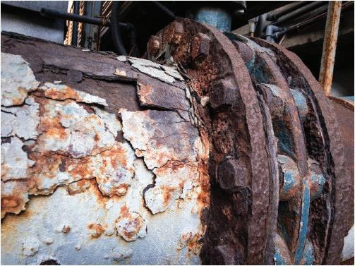
Additionally, lack of stress analysis and piping flexibility can result in excessive loads on the piping system, leakage from flanges, fatigue failure, damage to the piping and connected equipment, and operational problems. Figure 1.14 illustrates a disconnection of two flange joints from each other due to vibration and axial stresses. Corrosion is well known as the main cause of pipeline leakage in the oil and gas industry. Dents and gouges in the piping system are other reasons for piping and pipeline failures and leakage. A dent in piping and pipelines is defined as an inward, permanent, plastic deformation of the pipe wall that causes a distortion in the pipe cross-section (see Figure 1.15). A dent causes local stress and strain concentration as well as local reduction in piping diameter. A dent results in reduction of pipe strength against static and cycling loads, which could lead to bursting and leakage. Dents can be created by dropped objects, stresses and loads on the piping, poor manufacturing, accidents during shipping and installation of the piping components, etc.
Figure 1.13 Corrosion of flange and leakage. (Courtesy: Shutterstock).
Figure 1.14 Flange joint disconnection due to vibration and stress. (Courtesy: Shutterstock).
Dent in piping
Gouges in piping
1.3 Causes of Piping Failure and Leakage 11
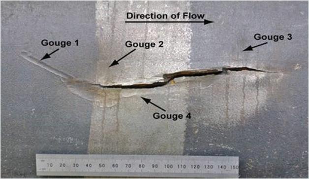
Figure 1.17 Stress cracking of a pipe in the vicinity of four gouges. (Courtesy: Transportation Safety Board of Canada).
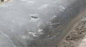
Gouges are defined as defects on the pipe wall where the thickness is locally reduced. Gouges are created when metal is removed from the pipe wall through mechanical means. Figure 1.16 illustrates gouges on the piping created during installation. The sharp edges of a gouge increase the stress concentration in the piping and can threaten piping integrity. Reduction in piping wall thickness lowers the pressure containment capacity of the pipe and could put the pipe at the risk of cracking and corrosion. Figure 1.17 illustrates stress cracking in the vicinity of four gouges on a pipe.
Different defects on the piping system could result in pipeline failure and leakage due to busting or rupture. Bursting or rupture of a pipe due to stress or corrosion, or a
Figure 1.15 Dent in piping.
Figure 1.16 Gouges in piping.
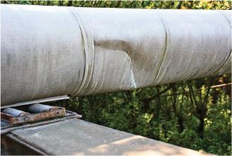
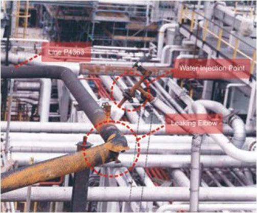
combination of both, is defined as a condition in which the pipe breaks open. Figure 1.18 illustrates a burst piping elbow in a refinery that failed due to erosion corrosion. Further investigations revealed that the leakage occurred from an elbow used to change the direction of the piping. The thickness of the elbow had been reduced from 7 or 8 mm to 0.3 mm due to erosion corrosion. Rupture of a pipe is a very severe type of pipe failure that results in significant emission and leakage to the environment. The hazards for the environment and for the people who are working onsite resulting from a burst or ruptured pipe are much greater than from piping leakage.
In conclusion, causes of piping leakage and emission are related to different aspects of material selection and corrosion analysis, piping component design and selection, manufacturing, transportation, fabrication, installation, and operation. Figure 1.19 shows the different factors that can cause piping failure, leakage, and emission. These can be summarized as poor piping component design; poor material selection and corrosion study; poor piping component selection; manufacturing issues; transportation, fabrication, and installation problems; and failures during operation. Piping failures due to loads and vibration are mainly categorized as problems during operation.
International and national codes and standards, American Society of Mechanical Engineers (ASME) and Norwegian petroleum standards (NORSOK), as well as piping handbooks and existing piping literature are used in this book to address the points that cause leakage from piping and piping components (excluding industrial valves) and to propose solutions to prevent leakage from piping systems.
Referring to the causes of piping failure and leakage illustrated in Figure 1.19, each chapter of this book is dedicated to solutions for preventing piping failure due to each cause. Chapter 2 focuses on design aspects of piping and piping components, such as wall thickness calculation and selection, as well as flange and fitting pressure class or rating determination. Chapter 3 addresses piping stress analysis due to different loads; such analysis is performed to mitigate piping failure due to loads during operation. Chapters 4 and 5 are dedicated to piping flange components, including gaskets and
Figure 1.18 Burst elbow in a piping system in a refinery. (Courtesy: Shutterstock).
Figure 1.19 Causes of piping failure and emission (leakage).
bolting; flange joint integrity; and leakage analysis. In addition, the application and usage of mechanical joints and compact flanges are discussed in Chapter 4. Mechanical joints and compact flanges, like standard flanges, are used to connect piping together with the possibility of dismantling the piping for maintenance or repair. But mechanical joints and compact flanges are more compact and lighter than standard flanges and have other additional benefits. Some calculations related to flanges, such as bolt length and loads and flange leakage analysis, are included in Chapter 5. Chapter 6 addresses piping material selection and corrosion prevention in different sectors of the oil and gas industry, such as offshore, refineries, petrochemical plants, etc. Poor piping component selection is another reason for piping failure. Thus, some tips for the selection of piping components based on piping codes and standards as well as industrial practices are provided in Chapter 7. Fabrication and installation of piping components as well as inspection and testing are discussed in detail in Chapter 8.
1.4 Leak Detection and Repair (LDAR)
LDAR programs are required by many standards and regulations. The main benefit of LDAR implementation is that it reduces emission from plants significantly. The EPA estimates that leakage rate can be reduced by 63% through the successful implementation of an LDAR program. LDAR is a work practice designed to identify leaks from possible leakage points, including piping and connections, and to repair them in order to reduce emission. Best practice for LDAR includes five steps: The first step is to identify the components that are at risk of leakage. All possible leakage points, such as flanges, should be selected and an identification number allocated to each one. The Transpor
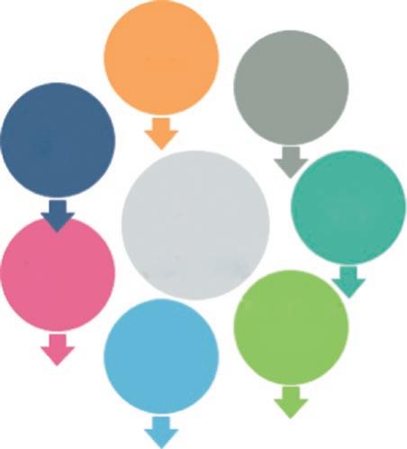
next step is to select the definition of leak. The lowest level of leak, such as 500 parts per million (ppm), is recommended. The third step is to monitor the components to detect possible defects and leaks. The proposal is to use EPA method 21 and an automatic data logging approach in order to save time and improve accuracy. The fourth step is to repair the components. Tightening or adjusting the bolts on the flanges could be a repair action. Different repair techniques for piping systems, mainly pipelines, are mentioned in this section. The last step is to keep a record and a data base of the components that are repaired. All of these essential LDAR steps are summarized in the flow chart illustrated in Figure 1.20.
Repairs could be undertaken by modifying or replacing the leaking components with leak-free components. ASME PCC-2 is one of the standards that addresses the repair of piping and pressure vessels. Different types of piping and pipeline defects may result in the need for maintenance and repair; these include corrosion and cracks, dents, welding defects, manufacturing defects, and gouges. Different techniques for repairing corroded or damaged piping to prevent leakage are discussed briefly below.
1.4.1 Composite Repair
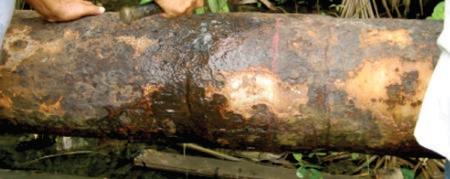
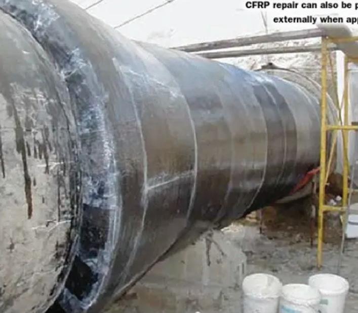
Composite overwrap repair is a method of piping rehabilitation. It is a popular choice of repair for piping and pipeline leakage due to corrosion, denting, cracking, and other causes listed in ASME PCC-2. The main objective of composite overwrap is to reinforce the corroded wall of the piping. The use of a nonmetallic composite repair system for piping, pipeline, and pressure vessel equipment is fully explained in Article 401, part 4 of the ASME PCC-2 standard. Figure 1.21 illustrates a corroded pipe; repairing such a pipe by wrapping it with composites is illustrated in Figure 1.22. The materials used in composite wrapping repair include but are not limited to glass, aramid, and carbon fiber reinforcement in a thermoset polymer such as polyester, polyurethane, phenolic, epoxy, etc. The composite strip is wrapped around the pipe by hand several times. It is important that the workers are well-trained and skillful in wrapping the composite around the pipe. The personnel should be aware of the hazards associated with wrapping composite around a degraded, pressurecontaining pipe.
Identifying Components
Leak Definition
Monitoring Components
Repairing Components
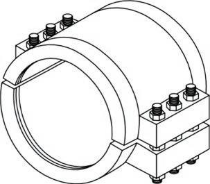
1.4.2 Mechanical Clamp Repair
Recordkeeping
Figure 1.20 LDAR steps and flow chart as per EPA.
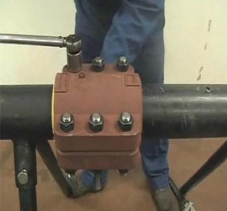
A mechanical clamp consists of two split fitting clamps that are bolted together (see Figure 1.23). The mechanical clamps are installed on the leaked or damaged part of the piping to seal and/or reinforce the area. The surface of the pipe where the clamp is installed should be cleaned properly and be free from dirt and other contaminations. The clamp could be welded to the piping after installation. Figure 1.24 illustrates the installation of a clamp on
1.21 Corroded piping.
some damaged piping and flanges. A vent and drain plugs could be placed on the repair clamp to release the leaked fluid from the pipe through the clamp during assembly and before tightening the clamp bolts on the piping.
1.4.3 Welded Leak Box Repair
Welded leak box repair consists of placing a pipe jacket with end pieces around the damaged or leaking section and seal welding it to the pipe. Seal welding is performed on two joints to provide some tightness against leakage. Figure 1.25 illustrates a welded leak box; as its name indicates, it is welded around a pipe like a jacket.
Figure
Figure 1.22 Composite wrapping around a pipeline as a means of repair.
Two half clamps
1.4.4 External Weld Overlay
The main concept of external weld overlay, as illustrated in Figure 1.26, is to deposit weld reinforcement on the surface of a pipe. Several considerations should be taken for the welding task, such as the compatibility of the welding filler with the base material, the number of welding passes and the application of a post-weld heat
Bolt and nut
Figure 1.23 Mechanical clamp for piping repair.
Figure 1.24 Clamp installation on piping for repair.
Figure 1.25 Welded leak box welded around a pipe.
1.4 Leak Detection and Repair (LDAR) 17
treatment (PWHT) or other treatment to reduce the residual stress. PWHT is a method in which the welding joint is heated to a specific temperature and held at that temperature for a certain amount of time in order to release the residual stresses accrued during the welding. It should be noted that PWHT is not always required as per piping code requirement. As an example, typically PWHT is not applied on austenitic stainless steels since this type of stainless steel can be corroded in high temperature. More information about austenitic stainless steels and the intergranular stress cracking corrosion of them at high temperature is provided in Chapter 6. As an example, if some part of a pipe has a flaw or defect that reduces the pipe wall thickness at that area, welding an external overlay plate on the defective area of the pipe can compensate for the insufficient thickness of the pipe and PWHT could be applied after welding the overlay plate to relief the residual stress of the welding.
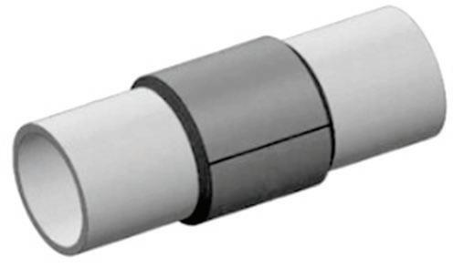
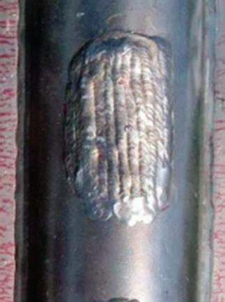
1.4.5 Sleeve Repair
A sleeve is a hollow, cylindrical tube placed around a damaged, corroded, or degraded pipe as a means of repair and to prevent leakage from the pipe. Full encirclement steel reinforcing sleeves for piping is explained in Article 206 of ASME PCC-2. The welding of the sleeve is performed along two longitudinal seams. Figure 1.27 illustrates a sleeve welded around a damaged pipe. One longitudinal weld is shown in the figure; the other longitudinal weld is located on the other side of the figure, which is not visible.
Figure 1.26 External weld overlay.
Longitudinal weld
Fillet weld
Repair sleeve
Pipe
Figure 1.27 Type B sleeve for pipe repair.
Two ends of the sleeve are fillet welded to the pipe, which is known as a Type B sleeve. A Type A sleeve is another type of pipe repair sleeve without any circumferential weld (fillet weld) to the carrier pipe. Buttweld is a type of welding in which the whole cross-section areas of the pipe are welded together. Fillet weld is a type of welding between two joints when they are perpendicular or at an angle to each other.
1.5 Questions and Answers
1 Which sentences are correct regarding fugitive emission from piping components?
A Piping joints, such as flanges, are responsible for the highest percentage of fugitive emission from refineries.
B Leakage of methane from a flange connection can contribute to the greenhouse effect and global warming.
C Leak detection and repair (LDAR) is a good strategy for reducing fugitive emission.
D Fugitive emission does not have any financial consequences for the companies responsible.
Answer: The highest percentage of fugitive emission comes from valves. In facts, 60% of fugitive emission in refineries comes from valves, while just 5.3% of fugitive emission comes from piping joints (flanges). Thus, the highest percentage of fugitive emission is not associated with flanges and piping joints, so option A is not correct. Option B is correct, because the leakage of methane from a flange or any other component does contribute to the greenhouse effect and global warming. Option C is correct, since LDAR is a good approach and strategy for reducing fugitive emission. Option D is not correct, since fugitive emission from refineries, chemical plants, and other production units does result in fines for these companies.
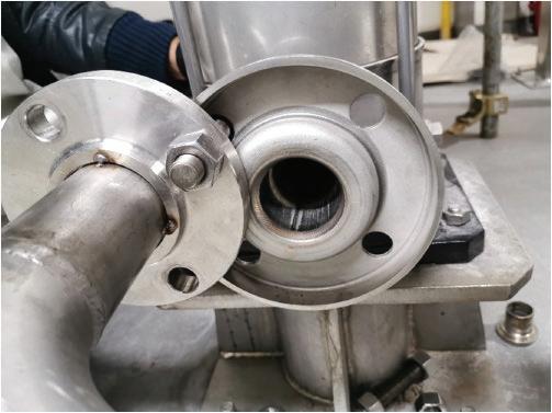
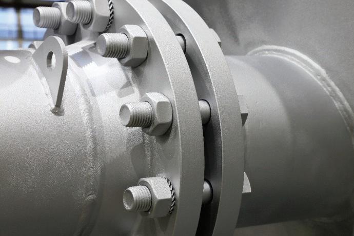
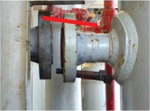
2 Which piping problem is illustrated in Figure 1.28, and at what stage in the lifecycle of the piping can this problem occur?
A Bolting removal from flanges during installation
B Flange face damage during installation
C Flange misalignment during either installation or operation
D Piping ovality during manufacturing
Answer: The problem is misalignment of the flange. The misalignment could happen either during installation or operation. To align the flange, the bolts and nuts should be removed from the flange before aligning the two flanges together. Thus, option C is correct. The face of the flange where the gasket sits is not visible in the figure, so option B is not correct. The misalignment of the flange could occur during operation due to the effect of loads and vibration. Piping out of roundness or ovality is not a problem in this case, so option D is not correct. Out of roundness or ovality is a piping problem that can occur during manufacturing.
Figure 1.28 Flange alignment process. (Courtesy: Shutterstock).
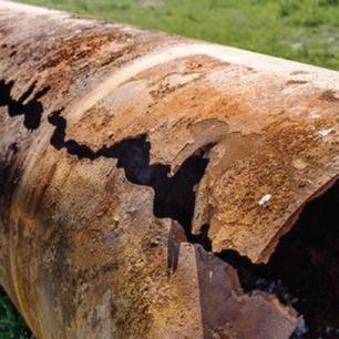
Figure 1.29 Piping failure. (Courtesy: Shutterstock).
3 What is the cause of most pipeline failures? What type of piping failure is illustrated in Figure 1.29?
A Erosion is the main cause of pipeline failure; the figure shows a corrosion failure.
B Stress and loads are the main causes of pipeline failure; the figure shows an erosion failure.
C Soil and sunlight are the main causes of pipeline failure; the figure shows an erosion failure.
D Corrosion is the main cause of pipeline failure; the figure shows a corrosion failure.
Answer: The main cause of pipeline failure is corrosion; the figure illustrates a corrosion failure in the piping. Thus, option D is the correct answer.