
Electrical and Mechanical Fault Diagnosis in Wind Energy Conversion Systems Monia Ben Khader Bouzid
Visit to download the full and correct content document: https://ebookmass.com/product/electrical-and-mechanical-fault-diagnosis-in-wind-ene rgy-conversion-systems-monia-ben-khader-bouzid/

More products digital (pdf, epub, mobi) instant download maybe you interests ...

Mechatronics: Electronic Control Systems in Mechanical and Electrical Engineering 7th Edition William Bolton
https://ebookmass.com/product/mechatronics-electronic-controlsystems-in-mechanical-and-electrical-engineering-7th-editionwilliam-bolton/

Mechanical and Electrical Systems in Architecture, Engineering and Construction 5th Edition – Ebook PDF Version
https://ebookmass.com/product/mechanical-and-electrical-systemsin-architecture-engineering-and-construction-5th-edition-ebookpdf-version/

Electrical Systems 2: From Diagnosis to Prognosis
Hubert Razik
https://ebookmass.com/product/electrical-systems-2-fromdiagnosis-to-prognosis-hubert-razik/

Thermal, mechanical, and hybrid chemical energy storage systems Klaus Brun (Editor)
https://ebookmass.com/product/thermal-mechanical-and-hybridchemical-energy-storage-systems-klaus-brun-editor/

Electrical Systems 1 From Diagnosis to Prognosis Hubert Razik
https://ebookmass.com/product/electrical-systems-1-fromdiagnosis-to-prognosis-hubert-razik/

Nanostructured, Functional, and Flexible Materials for Energy Conversion and Storage Systems 1st Edition Alagarsamy Pandikumar
https://ebookmass.com/product/nanostructured-functional-andflexible-materials-for-energy-conversion-and-storage-systems-1stedition-alagarsamy-pandikumar/

Mechanical and Electrical Equipment for Buildings 12th Edition, (Ebook PDF)
https://ebookmass.com/product/mechanical-and-electricalequipment-for-buildings-12th-edition-ebook-pdf/

Innovative Energy Conversion from Biomass Waste Arif Darmawan
https://ebookmass.com/product/innovative-energy-conversion-frombiomass-waste-arif-darmawan/

Data-Driven and Model-Based Methods for Fault Detection and Diagnosis Majdi Mansouri
https://ebookmass.com/product/data-driven-and-model-basedmethods-for-fault-detection-and-diagnosis-majdi-mansouri/

Electrical and Mechanical Fault Diagnosis in Wind Energy Conversion Systems
Edited by
First published 2023 in Great Britain and the United States by ISTE Ltd and John Wiley & Sons, Inc.
Apart from any fair dealing for the purposes of research or private study, or criticism or review, as permitted under the Copyright, Designs and Patents Act 1988, this publication may only be reproduced, stored or transmitted, in any form or by any means, with the prior permission in writing of the publishers, or in the case of reprographic reproduction in accordance with the terms and licenses issued by the CLA. Enquiries concerning reproduction outside these terms should be sent to the publishers at the undermentioned address:
ISTE Ltd
John Wiley & Sons, Inc. 27-37 St George’s Road 111 River Street London SW19 4EU Hoboken, NJ 07030 UK USA
www.iste.co.uk
www.wiley.com
© ISTE Ltd 2023
The rights of Monia Ben Khader Bouzid and Gérard Champenois to be identified as the authors of this work have been asserted by them in accordance with the Copyright, Designs and Patents Act 1988.
Any opinions, findings, and conclusions or recommendations expressed in this material are those of the author(s), contributor(s) or editor(s) and do not necessarily reflect the views of ISTE Group.
Library of Congress Control Number: 2023938459
British Library Cataloguing-in-Publication Data
A CIP record for this book is available from the British Library
ISBN 978-1-78630-931-0
BEN KHADER BOUZID and Gérard CHAMPENOIS
Chapter 1. Accurate Electrical Fault Detection in the Permanent Magnet Synchronous Generator and in the Diode Bridge Rectifier of a Wind Energy Conversion System ..................................
Monia BEN KHADER BOUZID and Gérard CHAMPENOIS
1.1. Introduction ....................................
1.2. Description of the system under study and the used fault detection method ...................................
1.3. Fundamental notions of the symmetrical components
1.4. Development of the analytical expressions of the NSV in the case of the different considered faults ................ ...
1.4.1. Analytical expression of V2 in the case of simultaneous faults ... 7
1.4.2. Analytical expression of V2 in the case of ITSCF in the PMSG .. 12
1.4.3. Analytical expression of V2 in the case of OCDF in the rectifier .. 14
1.5. Analytical study of the indicators of the different faults .........
1.5.1. Analytical study in the case of ITSCF ..................
1.5.2. Analytical study in the case of OCDF in the rectifier .. .......
1.5.3. Analytical study in the case of SF ....................
1.6. Experimental validation of the proposed fault indicators . ........ 25
1.6.1. Description of the tests process ......................
1.6.2. Experimental results in the case of healthy operation .. ....... 26
1.6.3. Experimental results in the case of ITSCF in the PMSG .. .....
1.6.4. Experimental results in the case of an OCDF fault in the rectifier . 29
1.6.5. Experimental results in the case of SF in the system considered .. 31
Chapter 2.
and Diagnosis of Faults in Multiphase
and Pedro GONÇALVES
2.1.
2.2.
2.3.
2.5.
2.5.1.
2.5.2.
2.5.3.
2.5.4.
2.6.
2.6.3.
2.6.4.
2.6.5.
2.6.6.
2.7.
2.8.
Chapter 3.
3.3.
3.4.
3.4.1.
3.4.2.
3.4.3.
3.6.
3.7.
Chapter 4. Control of a Wind Distributed Generator for Auxiliary Services Under Grid Faults
Youssef KRAIEM and Dhaker ABBES
4.1.
4.2.
4.3.
4.3.1.
4.4.
4.4.1.
4.4.2.
4.4.3.
4.4.4.
4.5.
4.5.2.
4.6.
4.6.1.
4.6.2.
4.7.
4.8.
Chapter 5. Fault-Tolerant Control of
5.1.
5.2.
5.3.
5.3.1.
5.3.2.
5.3.3. Proposed RFFTC stability and robustness analysis .......... 170
5.3.4. WES with DFIG application ....................... 171
5.3.5. Simulations and results .......................... 174
5.4. RFSFTC of WES with DFIG subject to sensor and actuator faults ... 178
5.4.1. TS fuzzy plant model with actuator faults, sensor faults and parameter uncertainties ............................ 179
5.4.2. Proposed RFSFTC algorithm based on FPIEO and FDOS ..... 180
5.4.3. Derivation of the stability and robustness conditions .. ....... 181
5.4.4. WES with DFIG application and simulations and results .. .... 183
5.5. RDFFTC of hybrid wind-diesel storage system subject to actuator and sensor faults .............................. 186
5.5.1. Fuzzy observer scheme for the uncertain system with sensor and actuator faults ............................. 187
5.5.2. Proposed RDFFTC, reference model and stability analysis ..... 188
5.5.3. HWDSS application and simulations and results .......... . 191
5.6. Conclusion ....................................
5.7. References ....................................
Introduction
Wind energy plays a vital role in meeting the Paris Agreement’s goal of 1.5°C global warming and to accelerate the energy transition. In fact, wind energy is a renewable and sustainable source of energy, which does not contribute to greenhouse gas emissions, making it an important tool in combating climate change. As the cost continues to decrease significantly and technology improves, wind energy is becoming more competitive with other sources of energy an increasingly important part of the global energy mix.
According to the Global Wind Energy Council (GWEC), the cumulative capacity of wind power installed worldwide reached 841 GW at the end of 2022. The growth of wind power capacity installation is expected to continue in the coming years as more countries implement policies and invest in renewable energy to reduce their carbon footprint and combat climate change.
A wind energy conversion system is an important technology for generating clean renewable energy and reducing our dependence on fossil fuels. The operating mode of this system consists on capturing the power of the wind and converts it into usable electrical energy. The system typically consists of several key components, including wind turbines composed of blades that capture the kinetic energy of the wind and convert it into rotational motion, the generator that converts the rotational motion of the rotor blades into electrical energy, the power electronic system including inverters, rectifiers and other components that convert the AC power
Introduction written by Monia BEN KHADER BOUZID and Gérard CHAMPENOIS
x Electrical and Mechanical Fault Diagnosis in Wind Energy Conversion Systems
produced by the generator into a form that can be used by the grid or stored in batteries and the control system responsible for regulating the speed and direction of the rotor blades to optimize the efficiency of the wind turbine.
However, wind energy conversion systems are subject to various types of faults which can impact their reliability and efficiency. These faults can be electrical or mechanical faults. Electrical faults can occur in generators, transformers, power converters and cables. These faults can result in reduced power output, increased maintenance requirements and potentially dangerous situations such as electrical arcing. Mechanical faults can occur in blades, bearings and gears. These faults can result in increased vibration, noise and wear and can ultimately lead to component failure if not addressed.
Therefore, fault detection in wind energy conversion systems is of great important to ensure their reliability, safety and efficiency. Regular maintenance and monitoring can also help to detect them before they lead to downtime or major repairs. Additionally, advanced control and monitoring systems can help to optimize the performance of wind energy conversion systems and reduce the risk of faults occurring.
Thus, this book is an opportunity for readers to deepen their understanding of the theories and concepts related to the topic of electrical and mechanical fault detection and diagnosis in the different components of a wind energy conversion system, as well as to gain insight into the practical applications and the results achieved in the field. To this end, many researchers from the scientific community have contributed to this book in order to share their research results. This book is organized into an Introduction and five chapters.
Chapter 1, AccurateElectricalFaultDetectioninthePermanentMagnet
SynchronousGeneratorandintheDiodeBridgeRectifierofaWindEnergy ConversionSystem, written by Monia Ben Khader Bouzid and Gérard Champenois, proposes an efficient symmetrical component-based method, able to detect, locate and discriminate between an inter-turns short-circuit fault in the permanent magnet synchronous generator and an open-circuit diode fault in the diode rectifier of a small-scale wind conversion energy system. The first part of this chapter will be dedicated to an original analytical study of the negative sequence voltage under the different considered faults, where novel expressions of the negative sequence voltage
are developed. Afterward, as a second part, an analytical study of the different proposed indicators of faults will be presented to investigate the behavior of the proposed indicators under the different faulty modes. Then, the third part of this chapter will be focused on the experimental validation of the behavior of the proposed indicators of fault and the novel developed expressions of the negative sequence voltage. Finally, a detailed description of the proposed method will be introduced in the fourth part of this chapter.
Chapter 2, ControlandDiagnosisofFaultsinMultiphasePermanent MagnetSynchronousGeneratorsforHigh-PowerWindTurbines, written by Sérgio Cruz and Pedro Gonçalves, presents a general overview of the existing control systems and diagnostic methods available for diagnosing faults in multiphase PMSM drives applied in wind energy conversion systems. After a general overview of the modelling of multiphase PMSM machines, the most common control algorithms of multiphase PMSM drives are presented, including field oriented control, direct torque control and model predictive control (MPC). Special emphasis is given to MPC algorithms due to their increasing popularity and adequacy in the control of this category of drives. Following this, recent diagnostic methods are presented to detect different types of machine and converter faults, including inter-turn short-circuits, high-resistance connections, open-phase faults in the machine and in the power switches, permanent magnet faults, mechanical faults and sensor faults.
Chapter 3, GearboxFaultsMonitoringUsingInductionMachine ElectricalSignals, written by Khmais Bacha and Walid Touti, first presents the theoretical basis of the AM-FM effect of gear faults on the driven machine stator current using the machine current signal analysis technique (MCSA). Then, the MCSA is compared to various recent methods such as the extended Park vector approach (EPVA) and the discrete cosine/discrete sine transform used for the gear fault diagnosis purpose. Based on the experimental results, these methods are investigated in terms of fault sensitivity to frequency levels.
Chapter 4, ControlofaWindDistributedGeneratorforAuxiliary ServicesUnderGridFaults, written by Youssef Kraiem and Dhaker Abbes, presents an intelligent control strategy based on fuzzy logic technology for a renewable distributed generator (RDG) integrated into power electrical system in order to keep the frequency and the voltage of the power grid in an allowable range, while ensuring the continuity of the power supply in the
Mechanical
event of a grid fault. The RDG comprises a wind system, as a principal source and a hybrid storage system consisting of battery (BT) and supercapacitors (SC). RDG is associated with loads and a fluctuating power grid. The structure of the proposed control strategy is mainly composed of a fuzzy logic supervisor, a fuzzy detector of the standalone operation mode and an adaptive fuzzy droop control. The fuzzy supervisor is developed to manage the power flows between different sources by choosing the optimal operating mode, while ensuring the stability of the power grid and the continuous supply of loads by maintaining the state of charge of the BT and SC in acceptable levels to improve their lifespans. The fuzzy islanding detector is used to detect the standalone mode in the event of power grid failure. The adaptive fuzzy droop control allows for controlling active and reactive powers exchanged with the power grid, ensuring its stability by maintaining frequency and voltage within optimal margins.
Chapter 5, Fault-TolerantControlofSensorsandActuatorsAppliedto WindEnergySystems, written by Elkhatib Kamal and Abdel Aitouche, proposes an observer-based actuator or sensor detection scheme for TS (Takagi-Sugeno) type fuzzy systems subject to sensor faults, parametric uncertainties and actuator faults. The detection system provides residuals for detecting and isolating sensor faults that may affect a TS model. The fuzzy TS model is adopted for fuzzy modeling of the uncertain nonlinear system and establishing fuzzy state observers. Sufficient conditions are established for robust stabilization in the sense of Lyapunov stability for the fuzzy system. The sufficient conditions are formulated in the form of linear matrix inequality (LMI). The effectiveness of the proposed controller design method is finally demonstrated on a DFIG-based wind turbine to illustrate the effectiveness of the proposed method.
Accurate Electrical Fault Detection in the Permanent Magnet Synchronous Generator and in the Diode Bridge Rectifier of a Wind Energy Conversion System
1.1. Introduction
Nowadays, it is a necessity to combat climate change by reducing the emission of greenhouse gases, notably carbon dioxide and methane. Reducing emissions requires essentially generating electricity from renewable energy sources non-emitting carbon. Wind energy is one of the most worldwide used renewable energy, and it is the fastest-growing energy source among the new power generation sources. Wind energy is already rapidly developing into a mainstream power source in many countries of the world, with over 841 GW of installed capacity worldwide (GWEC 2022). This has driven the rapid development and the high-capacity installation of wind energy conversion systems everywhere in the world, onshore and offshore. However, as any system, a wind energy conversion system may be subjected to various types of faults that may negatively affect the continuity of the electrical production and the reliability of such systems. Thus, the implementation of a
Chapter written by Monia BEN KHADER BOUZID and Gérard CHAMPENOIS
For a color version of all figures in this chapter, see www.iste.co.uk/benkhaderbouzid/fault.zip.
monitoring and diagnosis system based on efficient fault detection and diagnosis methods is of great importance to ensure the safety and reliability of a wind energy conversion system.
As the generator and its associated converters are the main electrical components in the energy conversion process of a wind turbine system (Bahloul et al. 2023), this chapter is focused on the detection of the inter-turn short-circuit fault (ITSCF) in the stator windings of the permanent magnet synchronous generator (PMSG) and the open-circuit diode fault (OCDF) in the three-phase diode rectifier connected to the PMSG. Each type of fault can occur separately or two may occur simultaneously. In the case of a simultaneous fault, it is very difficult to discriminate between the two faults. To this end, this chapter proposes an efficient method based essentially on the symmetrical components to detect, locate and discriminate between an ITSCF and an OCDF in a small-scale, variable-speed wind energy conversion system.
This chapter will be organized as follows. The description of the system under study and the principle of the used method is given in section 1.2. The fundamental notions of the symmetrical components are presented in section 1.3 to facilitate the understanding of the presented work. In section 1.4, an original analytical study of the negative sequence voltage (NSV) under the different considered faults is elaborated where new expressions of the NSV under the different considered faults are developed. In section 1.5, the behaviors of the proposed fault indicators are studied analytically. These proposed fault indicators are experimentally validated in section 1.6. The description of the principle of the proposed method using the different fault indicators to detect, discriminate and locate the different considered faults is presented in section 1.7. Finally, a conclusion is drawn in section 1.8.
1.2. Description of the system under study and the used fault detection method
A wind energy conversion system is a cost-effective way to generate clean electricity and protect the environment. This system typically consists of large blades that capture the kinetic energy of the wind and convert it into mechanical power. This mechanical power spins then the generator shaft, which produces electricity. Wind energy conversion systems can be
conceived on a small or large scale, onshore or offshore, with fixed or variable speeds and connected or not to the main grid.
In any wind energy conversion system, the key component responsible for the conversion of wind energy to electrical energy is the generator. The typically-used wind turbine generators are a doubly-fed induction generator (DFIG), wound rotor synchronous generator (WRSG), squirrel-cage induction generator (SCIG) and permanent-magnet synchronous generator (PMSG) (Liang et al. 2022). In the last decade, due to its several advantages, the PMSG has gained significant popularity and is becoming widely used in wind energy conversion systems (Yuan et al. 2021). As it has been reported in Gliga et al. (2008), the PMSG faults represent 14.7% of all faults in a WTS, and they account for 24.42% of the downtime.
On the other hand, the wind turbine generator is interfaced with the utility grid via power electronic converters used to transfer and control the wind power into the electric grid. Typically, wind turbine converters include diode rectifier-based converter topology, two-level back-to-back converter topology, three-level neutral-point-clamped back-to-back converter topology and modular multilevel converter topology (Yang et al. 2016). It has been reported in Liang et al. (2022) that the fault of power semiconductor devices is one of the main causes responsible for converter faults. Typical faults of power semiconductor devices can be divided into short-circuit (SC) faults and open-circuit (OC) faults. The OC faults are the most common
Based on these considerations, this work is interested in the PMSG-based wind turbine structure. However, according to this structure, there are two configurations: PMSG with back-to-back voltage source converters and PMSG with diode rectifiers and boost converters. This chapter is focused on the configuration of the PMSG connected to a diode rectifier-based converter, since this configuration is widely used to interface direct-drive wind conversion energy systems, due to its simplicity and its low cost (Yang et al. 2016). Figure 1.1 shows the block diagram of a small-scale wind conversion system based on a PMSG connected to a diode rectifier. This system is composed of a wind turbine (three blades), a PMSG, a three-phase diode bridge rectifier, a boost chopper and a DC bus. However, the system under study is limited only to the PMSG and the three-phase diode rectifier highlighted in yellow in Figure 1.1.


1.1. Small-scale, PMSG variable speed wind energy conversion system
To ensure the reliability and increase the safety of the system under study, this work is aimed at finding an efficient method capable of detecting, locating and discriminating between two electrical faults, which are an interturn short-circuit fault (ITSCF) in the stator of the PMSG and an OCDF in the three-phase diode bridge rectifier. This interest is justified by the fact that the ITSCF is the most frequent fault in the machine (Qiao and Lu 2015), and it is a critical and harmful one when detected in the PMSG. It shapes more than one-third of the total faults in the PMSG (Sayed et al. 2021). However, the OCDF in a diode rectifier, although it may not seriously stop the operation of the wind turbine system, can result in overstressing the other healthy diodes and cause the failure of other diodes (Huang et al. 2021).
The proposed fault detection and diagnosis method are based on the monitoring of different relevant indicators of faults extracted basically from the symmetrical components of voltages and currents. It consists first of monitoring the magnitude of the PMSG NSV V2 to detect any fault in the considered system. Afterward, the mean values of the line currents are used to discriminate between an ITSCF and OCDF since a fault can occur in the PMSG or the rectifier. Furthermore, in the case of an ITSCF or/and an OCDF, the location of the PMSG faulty phase or/and the rectifier’s faulty arm is ensured by the monitoring of the phase angle φV2 of the NSV and the phase angle φI2 of the negative sequence current (NSC), respectively. The potential features of these indicators to detect, discriminate and locate the considered faults will be demonstrated in the next sections through an
original deep and thorough analytical study of the NSV under the different faults where novel NSV expressions will be developed and presented taking into account the encroachment effect of the current and the placement of the different turns in the slots of the PMSG stator. The behavior of the NSV and the NSC as well as the exactness of the proposed novel expressions will be validated for each fault. However, before investigating the analytical behavior of the NSV under ITSCF and OCDF, let us give first, a brief description of the symmetrical component principle.
1.3. Fundamental notions of the symmetrical components
In a balanced three-phase electrical system composed of a balanced three-phase voltage source connected to a balanced three-phase load, a balanced set of three-phase currents is drawn. In this case, the three-phase voltages are with equal amplitude and 120° spacing. Similarly, the three currents also have equal amplitudes and 120° spacing, but with a phase shift with respect to the voltage due to the lagging or leading loads as illustrated in Figure 1.2.
However, in an unbalanced system, the above principle is no longer true. To simplify the investigation of an unbalanced three-phase system, in 1918 (Furfari et al. 2002), Charles Fortescue suggested that any three-unbalanced phasors can be expressed as the sum of three sets of balanced phasors. Thus, as Fortescue states, an unbalanced three-phase voltage or current system can be decomposed into three symmetrical sets of balanced voltages or currents.
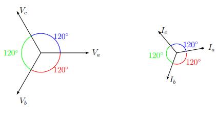
Figure 1.2. A balanced system of three voltages and currents
Figure 1.3 illustrates graphically the decomposition of an unbalanced three-phase voltage (Figure 1.3(a)) into three balanced voltages sequences
(Figure 1.3(b)), which V1 is called the positive sequence component. It is called positive since it has the same order of phases as in the original set, that is, a → b → c clockwise. V2 , on the other hand, is referred to as the negative sequence component since it has a flipped order of phases, that is, a → c → b. The last component V0 is called the zero sequence component and it consists of three phasors of the same phase shift, that is, a non-rotating set. Similarly, an unbalanced three-phase current system can be decomposed into a positive sequence component I1 , a negative sequence component I2 and a zero sequence component I0 .
Mathematically, the expressions of the three symmetrical components can be obtained using Fortescue’s matrix F:
Thus, by applying Fortescue’s matrix to an unbalance of three-phase voltages 123 (V,V,V) and currents 123 (I,I,I) , the expressions of the positive, negative, and zero sequences of voltage and current are given by [1.2] and [1.3], respectively.
Positive sequence voltage Negative sequence voltage Zero sequence voltage b)
Figure 1.3. Three-phase unbalanced system: (a) unbalanced voltages; (b) their graphical decomposition into three symmetrical components: positive, negative and zero sequences
1.4. Development of the analytical expressions of the NSV in the case of the different considered faults
The objective of this novel original analytical study is to develop analytical expressions of the NSV in the three cases of fault, the ITSCF in the machine named machine fault (MF), the OCDF in one arm of the diode full-bridge rectifier named rectifier fault (RF) and the two faults simultaneously named simultaneous faults (SF).
1.4.1. Analytical expression of V2 in the case of simultaneous faults
To develop the expressions of the NSV in presence of SF, we consider the equivalent electrical circuit illustrated in Figure 1.4. In this circuit, the
faulty PMSG presents an ITSCF of Nsa shorted turns in phase “a” as an example of ITSCF. This faulty machine is connected to a three-phase diode rectifier with an OCDF modeled by an unbalanced load composed of three unbalanced impedances (Bouzid and Champenois 2017).
The three unbalanced currents flowing in the circuit are denoted () abc I,I,I . The ITSCF is quantified by the factor “xa” which is a relative number equal to the ratio between Nsa and the total number Nt of turns in the healthy phase, as expressed by [1.4].
xa = Nsa/Nt
Figure 1.4. The equivalent electrical circuit of the faulty PMSG with an ITSCF in phase “a”“ connected to an unbalanced load
In general case, for any ITSCF in the phase “i” (i = a, b or c),
xi = Nsi/Nt
According to Figure 1.4, the expressions of the three electromotive forces (EMF) abc (E,E,E) and the impedance m Z of the healthy PMSG are given by [1.6] and [1.7], respectively.
with:
–Rm: phase resistance of the PMSG;
–Lm: self-inductance of the PMSG phase;
–Lc = Lm·(3/2-ft/2): cyclic inductance of the PMSG phase; [1.8]
– ꞷ = 2.π.f: pulsation of the system;
–f: frequency of the PMSG;
–ft: leakage flux ratio between phases.
By applying Kirchhoff’s voltage law to the equivalent circuit of Figure 1.4, the voltage equations VaN VbN VcN , between the neutral point N and the terminals “a”, “b” and “c” of the machine, can be written as follows: 2 2 (1)(1)j[(1) ()]()j..[() ] aNaaaaamaamaba1b ca1ca2a1daaamdaaamdaa ba2bca2ca1a2a
mcmca2cdaaa1cabcb R.I..[LIM.(II)M.IM.I] cNc VEj=−−ω++++ [1.11] With (())() 22 aaaaamamaamM1221=M=1x.L.x.L=x.1x.L
(1)(()) (1)(1).
abacbacatam tam M1111=M=M=M=f/2.1x.L =f/2.xL [1.13] ()()() 22 abacbacatamtam M2222=M=M=M=1f/2.x.L=1f/2.x.L [1.14]
ababbabaacaccaca tmaa t 12121212 M+M=M+M=M+M=M+M =1f/2.L.1x+x =1f/m .L
Electrical and Mechanical Fault Diagnosis in Wind Energy Conversion Systems ()[()] ()2
(1)2 Mbccbtm =M=f/.L [1.16]
The expressions of aNV , bNV , cNV can be reformulated according to [1.17] and [1.18].
V=Ex.R.I.ω.I.x.LR.I ω.L.If/2.I+I
j[(1)()]
aNaamdadamma matbc
j(1)2
bNbdaamtmb mbtca
j[(12()]
j(1)
cNcdaamtmc mctab V=E+..I.x.L.f/2R.I ..L.If/2.I+I ω−− −ω−−
j[(1)()]
Since b ca III +=− , cab III +=− and abc III +=−
aNaamdadaamma mat V=Ex.R.I..I.x.LR.I ..L.I.f/ −−ω− −ω−
j(3/22)
j(1)2 j(3/22)
bNbdaamtmb mbt V=E+..I.x.L.f/R.I ..L.If/ ω−− −ω−
j(1)2 j(322)
cNcdaamtmc mct V=E+..I.x.L.f/R.I ..L.I./f/ ω−− −ω−
Applying the complex Fortescue’s transformer of [1.1] to the voltages aNV , bNV , cNV , the expressions of the symmetrical components of these voltages are obtained according to [1.2]. Thus, the expression of the NSV
2aV generated by an ITSCF in phase “a” and an OCDF in the diode rectifier simultaneously is given by [1.23]:
2aaNbNcN V(Va.Va.V)/3 =++
The substituting of [1.20]–[1.22] in [1.23] yields:
mtabc .V=E+a.E+a.Ex.R.I..I.x.L +..I.x.L.1f/.a+aR.I+a.I+a.I ω L.f/I+a.I+a.I −−ω ω−−
with
I2a is the total NSC which is the superposition of the NSC 2a-ITSCF I generated by the ITSCF and the NSC 2-OCDF I generated by the OCDF.
Using [1.25] and [1.26], [1.24] becomes:
3j()/2(11) j33j...(). 2 2aamdadaamt amdam2amt2a .V=x.R.I..I.x.L.1f.a+a+ ..x.L.I.R.I. ω L3/2f/2I −+ω−− −ω−−− [1.28]
Since 10 a+2a+ = :
3j..j.(1)2 33j(3/22). 2aamdaamdadaamt m2amt2a .V=x.R.I.x.LI.I.x.L.f/ .R.I...L.f/I −−ω−ω− −−ω− [1.29]
3(j.()).3(j()). 2aammtdammt2a .V=x.R+.L.3/2f/2I.R+..L.3/2f/2I −ω−−ω− [1.30] (13)(.)(.) 2aamdam2a V=.x.ZIZI [1.31]
1.4.2. Analytical expression of V2 in the case of ITSCF in the PMSG
In this case, the considered equivalent electrical circuit is the circuit of Figure 1.4, where the unbalanced load is replaced by three balanced loads ( L Z ) modeling the healthy diode full-bridge rectifier. Thus, with no OCDF, the NSC 2 I-OCDF is null, and according to [1.27], the total NSC
2a2 IIa-ITSCF = . The NSC in the case of ITSCF is caused only by the NSV
2a-ITSCFV generated by the unbalance of the three voltages ( aNV , bNV , cNV ) due to the ITSCF. The expression of 2a I is then:
2a2a-ITSCF2a-ITSCFL
Substitution [1.32] in [1.31] yields: (13)(.)(.)
As ZL is higher than the machine impedance Zm, [1.33] can be approximated by:
The expressions of the magnitude V2a-ITSCF and the phase angle V2aITSCFϕ of the NSV 2a-ITSCFV are set by [1.35] and [1.36], respectively.
We can note here that 2a-ITSCFV and V2aITSCFϕ are insensitive to the load conditions and this is for any ITSCF in any phase “i” ( i = a, b or c). However, 2a-ITSCFV depends on the importance of the fault, the magnitude of the faulty current and the frequency, while V2aITSCFϕ depends only on the ratio Lc.ω/Rm which depends on the frequency and the phase angle of the faulty current.
With the same approach, the analytical expressions 2b-ITSCFV in the case of ITSCF in phase “b” and 2c-ITSCFV in the case of ITSCF in phase “c” are defined by [1.37] and [1.40], respectively.
In the general case, for an ITSCF in phase “i”, the expressions of V2i-ITSCF and φV2i-ITSCF are given by [1.43] and [1.44], respectively.
The faulty current Idi ( i = a, b, or c) is in phase with the corresponding faulty phase voltage iV ( VViii =∠ϕ ) since it flows in a pure resistance. As a result, Ii di ϕ = ϕ and the expression Idi will be as follows:
Accordingly, [1.44] can be reformulated as follows:
V2iITSCFZmi 180 ϕ = ϕ −°+ ϕ [1.46]
Thus, for an ITSCF in phase “i”, the phase angle V2iITSCF ϕ of the NSV is as follows:
V2aITSCFZm
V2bITSCFZm
V2cITSCFZm
1.4.3. Analytical expression of V2 in the case of OCDF in the rectifier
In this case of fault, the considered equivalent electrical circuit is the one of Figure 1.4, where the faulty machine is replaced by the healthy PMSG. Thus, with the absence of an ITSCF the faulty current da I = 0 and according to [1.27], 2a I will be equal to 2a-OCDF I ( 2a2a-OCDFII = ). Therefore, according to [1.31], we obtain:
The magnitude 2a-OCDFV and the phase angle V2aOCDFϕ of the NSV are then:
In the general case, for an OCDF in the arm “i”, i = a, b or c, the expressions of 2i-OCDFV and V2iOCDFϕ are as follows:
1.5. Analytical study of the indicators of the different faults
After developing the expression of the NSV in the previous section, we study here the behavior of the different indicators of faults that are the amplitude V2 and the phase angle φV2 of the NSV, the phase angle φI2 of the NSC and the average currents a
under different operating conditions to point out their potential features useful to detect, discriminate and locate the different faults.
Therefore, to elaborate an analytical study, it is necessary first to calculate the values of these different indicators under different operating conditions. The different variables are calculated using the parameters of the real machine used in the experiment. These parameters are represented in Table 1.1. The leakage flux ft is considered here as 30% of the total flux of the machine ft = 30%.
Table 1.1. Parameters of the used experimental machine
1.5.1. Analytical study in the case of ITSCF
The magnitude V2i-ITSCF and the phase angle φV2i-ITSCF of the NSV for an ITSCF in phase “i” are calculated analytically under different operating conditions using [1.43] and [1.44]. Note that to obtain correct values of φV2-ITSCF, it is necessary to take into account the physical distribution of the different turns housed in the different slots. As shown in Figure 1.5, which illustrates the mechanical distribution of the windings of a pair pole over a quarter of the used machine, coil a1 of the winding “a” is ahead of a mechanical angle of 10° and the coil a3 is behind of –10° in respect to the whole coil “a” under a pole pair.
Axis of 5 turns of a2 or 15 turns (a1+a2+a3)
Axis of 5 turns of a3 Axis of 5 turns of a1
Phase b
Phase c -10° +10
Figure 1.5. Mechanical distribution of the stator PMSG windings for a pair of poles over a quarter of the machine
As the machine has four pairs of poles, the electrical phase shift of the EMF of coil a1 will be 40° ahead of the total EMF of phase “a”, which is the sum of coils “a1”, “a2” and “a3”. The EMF of coil “a3” will have a phase shift of 40° with respect to the total EMF of phase “a”.
Thence, in all this work, it is necessary to add +40° to the voltage angle of 5 turns (a1), 20° to 10 turns (a2+a3) and 0° to 15 turns (a1+a2+a3), and the real phase angle will be φV2r instead φV2:
φV2ar-ITSCF = φV2a-ITSCF + 40° for 5 turns (a1)