OPERATIONAL AMPLIFIERS AND LINEAR INTEGRATED CIRCUITS
K. Lal Kishore
Registrar
JNTU, Hyderabad
Contents
Foreword
Preface
1. Operational Amplifiers Basics
1.1 Introduction
1.2 Operational Amplifiers
1.3 Classification of Operational Amplifiers
1.4 Symbol
1.4.1 Package
1.4.2 Identification Code
1.4.3 Temperature Ranges
1.4.4 Nomenclature
1.4.5 Power Supply Connections
1.4.6 Op-amp
1.4.7 Difference Amplifier
1.5 Operational Amplifier Parameters
1.5.1 Input Offset Voltage (VIO)
1.5.2 Input Offset Current (IIO)
1.5.4 Output Bias Current (IB)
1.5.5 Input Resistance (RI)
1.5.6 Input Capacitance (CI)
1.5.7 Input Offset Voltage Drift
1.5.8 Input Offset Current Drift
1.5.9 Common Mode Rejection Ratio [CMRR]
1.5.10 Power Supply Rejection Ratio (PSRR)
1.5.11 Slew Rate (SR)
1.5.12 Gain BW Product
1.5.13 Offset Voltage Adjustment
1.6 Frequency Roll off
1.6.1 Octave
1.6.2 Decade
1.7 Operational Amplifier in Open Loop Configuration
1.8 Operational Amplifier Going to Saturation
1.9 Virtual Ground
1.10 Op-amp A Direct Coupled High Gain Amplifier
1.11 Inverting Amplifier
1.11.1 Ideal Case
1.11.2 Input Impedance
1.11.3 Non-ideal Case
1.11.4 Output Impedance
1.11.5 Ideal Case: Non-Inverting Amplifier
1.11.6 Input Impedance
1.11.7 Non-ideal Case: Input Impedance
1.11.8 Output Impedance
1.12 Basic Linear Circuits Using Operational Amplifiers
1.12.1 Adder Circuit
1.12.2 Buffer Circuit
1.12.3 General Analysis of Op-amp Circuits
1.13 Ideal Operational Amplifier as a Subtractor
1.14 Ideal Operational Amplifier as an Integrator
1.15 Ideal Operational Amplifier as a Differentiator
1.16 Operational Amplifier Design Techniques
1.16.1 Biasing Method
1.16.2 Improved Version of Current Mirror Circuit
1.16.3 Active Loads
1.16.4 Level Shifting
1.16.5 Output Stage
1.17 Measurement of Operational Amplifier Parameters
1.17.1 Measurement of Offset Voltage and Current
1.17.2 Measurement of CMRR
1.17.3 Measurement of Open Loop Input and Output Impedances
1.18 Measurement of Power Supply Rejection Ratio (PSRR)
1.19 Measurement of Slew Rate
1.20 Measurement of Open Loop Gain
1.21 Frequency Response
Summary
SolvedExamples
Essay-TypeQuestions
Objective-TypeQuestions
Problems
Self-assessmentquestions
UnsolvedProblems
2. Op-amp Applications
2.1 Op-amp Circuits
2.2 Op-amp for Voltage and Current Measurements
2.3 Measurement of DC Voltage
2.4 Measurement of DC Current
2.5 AC Measurement
2.6 Operational Amplifier Reference Voltage Source
2.7 Operational Amplifier Half-wave Rectifier (HWR) Circuit
2.8 Operational Amplifier Full-wave Rectifier
2.9 Linear Rectifier
2.10 Logarithmic Amplifier
2.11 Antilogarithmic Amplifier
2.12 Log Multipliers
2.13 Schmitt Trigger
2.13.1 Speed Up Capacitor
2.13.2 Negative Feedback in Schmitt Trigger
2.14 Logarithmic Voltmeters
2.14.1 Principle
2.15 Texas Instruments TL441C IC
2.16 Offset Voltage Compensating Design
2.17 Operational Amplifier Clipper Circuits
2.18 Operational Amplifier Function Generator
2.18.1 Schmitt Trigger
2.18.2 Rectangular-to-Triangular Waveform Conversion
2.19 Differential Voltage to Current Converter or Constant Current Source with Grounded Lead
2.20 Constant High Current Source, Grounded Lead Circuit
2.21 Instrumentation Amplifiers: Op-amp Applications
2.22 Analysis
2.23 Sample and Hold Circuit
2.24 Terminology
2.24.1 Acquisition Time
2.24.2 Aperture Time
2.24.3 Holding Time
2.25 Constant Amplitude Phase Shifter
2.26 Voltage Series Feedback
2.27 Voltage Shut Feedback
2.28 Zero Crossing Detectors (Comparators)
2.28.1 Non Inverting Zero-Crossing Detector
2.28.2 Inverting Zero Crossing Detector
2.28.3 Level Detector Circuits
2.28.4 Inverting Positive Level Detector
2.28.5 Negative Level Detector (Non inverting)
2.28.6 Negative Level Detector (Inverting)
2.29 Op-amp Schmitt Trigger Circuit
2.30 Astable Multivibrator Using Op-amp
2.31 Op-amp Monostable Multivibrator
2.31.1 Op-amp Monostable Multivibrator Circuit
2.32 IC Monostable Multivibrator
2.33 Bistable Multivibrator with Op-amps
2.34 Gyrator
2.35 IC Waveform Generator: 8038
2.36 V/I Converter
2.37 Bridge Amplifiers
2.38 Resistance Bridge
2.39 Dead Zone with Positive Output
2.40 Signal Polarity Separator
2.41 Charge Amplifier
Summary
Fillin the Blanks
Essay-typeQuestions
UnsolvedProblems
3. Active Filters and Oscillators
3.1 Classification of Filters
3.2 Active Filters
3.2.1 Types of Active Filter Circuits
3.2.2 Advantages of Active Filter Circuits
3.2.3 Disadvantages of Active Filter Circuits
3.3 Passive Filters
3.3.1 Advantages of Passive Filter Circuits
3.3.2 Disadvantages of Passive Filter Circuits
3.4 Low Pass Network (Passive Filter Circuit)
3.5 High Pass Network (Passive Filter Circuit)
3.6 Notch Filter (Band Reject filter)
3.7 Band Pass Filter (BPF)
3.8 Low Pass Filter (LPF)
3.8.1 First Order Active Low Pass Filter (LPF)
3.9 High Pass Filter
3.9.1 First Order High Pass Active Filter
3.9.2 Second Order Low Pass Filter
3.9.3 Fourth Order Active Low Pass Filter
3.9.4 First Order Low Pass Filter Circuit
3.10 Sallen and Key Circuit
3.10.1 Second Order Low Pass Active Filter
3.10.2 Third Order Low Pass Active Filter
3.11 General Expression for Second Order High Pass Filter
3.11.1 Second Order High Pass Active Filters (Sallen and Key Circuits)
3.12 Band Reject Filter (BRF)
3.12.1 Band Reject Filters (BRF)
3.13 Active Resonant Band Pass Filter
3.14 Electrothermal (ETC) Filters: (ETH Filters) or ElectroThermal Resistance and Capacitance Filters
3.14.1 First Order High Pass Filter
3.14.2 Second Order High Pass Filter
3.15 Classification of Filters Based on Characteristics
3.15 Butterworth Filters
3.16 Chebyshev Filters
3.17 Bessel Filters
3.18 Elliptic Filters
3.19 All Pass Filters
3.20 Resonant BPF Circuit with R3 and C1 Interchanged
3.21 Operational Amplifier Oscillator Circuits
3.21.1 RC Phase Shift Oscillator
3.22 Window Detector or Discriminator
3.23 Op-amp Wien Bridge Oscillator
3.24 Switched Capacitor
3.24.1 Switched Capacitor Integrator
3.24.2 Stray Insensitive Integrator
3.24.3 First Order Switched Capacitor Filter
3.24.4 Second Switched Capacitor Filter
3.25 Analog Switches
3.25.1 Multiplexers
3.25.2 Multiplexer with MOSFET Switches
3.25.3 Multiplexer with JFET Switches
3.25.4 Multi-tiered Multiplexing
3.26 Line Drivers
3.26.1 Line Driving Amplifier
3.26.2 Line Drivers and Receivers
3.26.3 Multiplexer Circuit Principle
3.26.4 Analog Switches
Summary
Essay-typeQuestions
Fillin the Blanks
UnsolvedProblems
4. Timer and Phase Locked Loop ICs
4.1 NE 555 Timer
4.1.1 NE 555 as Astable Multivibratior
4.1.2 NE 555 Astable with 50% Duty Cycle
4.1.3 NE 555 as Monostable Multivibrator
4.1.4 Specifications of NE 555
4.1.5 NE 555 Monostable Multi Applications
4.1.6 Pulse Stretcher
4.1.7 Pin Configuration Functions of 555
4.2 Phase Locked Loop (PLL)
4.2.1 Applications
4.2.2 PLL Building Blocks
4.2.3 VCO Characteristics
4.2.4 Block Diagram of PLL
4.2.5 VCO Applications
4.2.6 Mechanical Analogy
4.2.7 Frequency Shift Keying
4.2.8 PLL Terminology
4.2.9 VCO Conversion Gain (K0)
4.2.10 AM Receiver Using PLL
4.2.11 NE/SE 565 PLL Block Diagram
4.2.12 Specifications of 565 PLL IC
4.2.13 Measurement of Capture and Lock Range
Summary
Essay-typeQuestions
Fillin the Blanks
UnsolvedProblems
5. Digital to Analog Converters (DACs) and Analog to Digital Converters (ADCs)
5.1 Introduction
5.2 D/A Converter
5.2.1 Weighted Resistor Network
5.2.2 R-2R Ladder Network
5.3 DAC with Memory
5.4 D/A Converter Specifications
5.5 A/D Converters
5.5.1 D/A Multiplexing
5.5.2 A/D Multiplexing
5.5.3 MOSFET as a Switch
5.6 Ramp Conversion: Counter Ramp Conversion Technique of ADC
5.7 Binary-coded Resistance Network for Successive Apporoximation Type A/D Conversion
5.8 Simultaneous A/D Converters (Flash Type)
5.8.1 Advantage
5.8.2 Disadvantages
5.9 General Description of One Class of A/D Converter
5.9.1 Limitations
5.10 Staircase Ramp DVM
5.11 Voltage to Time Conversion
5.12 Successive Approximation Type A/D Converter
5.13 Successive Approximation A/D Converter
5.14 Digital Voltmeter (DVM) Types
5.14.1 Specifications of DVMs (Typical Values)
5.15 Non-integrating Type DVMs
5.15.1 Potentiometric Type
5.15.2 Servo Type DVM
5.16 Ramp Type DVM
5.17 Integrating Type Digital Voltmeter
5.18 V/T Conversion
5.18.1 Single Slope V/T Conversion
5.18.2 Limitations
5.19 V/T Converters for A/D Conversion
5.19.1 Disadvantages
5.20 V/F Converter
5.20.1 Advantages
5.21 Dual Slope Integrating Type DVM
5.21.1 Advantage
5.21.2 Disadvantages
5.22 Specifications of A/D Converters
5.23 Automatic Polarity Indication for DVMs (Digital Voltmeters)
5.23.1 Auto Ranging
5.23.2 Typical Case
5.24 A/D Converter Terminology
5.25 Comparison of A/D Converters
5.25.1 Advantages of V/F Converter (Integrating Type)
5.25.2 Disadvantages
5.25.3 Voltage to Time Converter
5.25.4 Simultaneous A/D Converter
5.26 Commercial A/D Converters
5.27 Series Mode Rejection
5.28 Simultaneous A/D Conversion Using Tunnel Diodes
5.29 V/F Conversion: (Integrating Type ADC)
5.30 S/H Amplifiers in A/D Converters
Summary
Essay-typeQuestions
Fillin the Blanks
UnsolvedProblems
6. Voltage Regulators
6.1 Introduction
6.2 Voltage Regulators
6.2.1 Zener Voltage Regulator
6.2.2 Shunt Regulator Circuit
6.3 Unregulated Power Supply
6.3.1 Stabilisation
6.3.2 Series Voltage Regulation
6.3.3 Series Voltage Regulation Circuit
6.4 Voltage Regulators Terminology
6.5 Protection Circuits for Voltage Regulator ICs
6.5.1 Short Circuit Protection
6.5.2 Over Voltage Protection
6.6 IC 723 Voltage Regulator
6.7 Three-terminal Regulators
6.8 7900 Series
6.9 Protection Circuits
6.10 Simple Limiting Circuit
6.11 Foldback Limiting
6.12 Specifications of Voltage Regulator Circuits
6.13 DC to DC Conversion
6.14 Switching Regulators
6.15 Classification
6.16 Step-down (Buck) Switching Regulator
Summary
Essay-typeQuestions
Fillin the Blanks
UnsolvedProblems
Appendix A
Appendix B
Appendix C
Appendix D
Bibliography
To mywife,Gayatri and daughters,KalpanaandPratyusha
Foreword
I consider it a privilege to write the foreword for this book by Prof. K. Lal Kishore. Since the author has taught this subject for many years, it is apt that such a book be authored by him.
The Jawaharlal Nehru Technological University has often revised their curriculum to maintain currency with the requirements of the industry. Also, the practical aspects of the subject have been increasingly incorporated into the curriculum. This book is an essential text as it fulfils both, theoretical and practical, requirements equally.
K. RAJAGOPAL VICE-CHANCELLOR JNTU HYDERABAD
Preface
The fag end of the 20th century saw a technology revolution, after which integrated circuits have come to play an important role in various industries. Although digital circuits are used widely, the role of analog circuits and linear integrated circuits (ICs) is no less important. These topics, therefore, need to be addressed from a student’s point of view and their applications explained in more detail. In the light of these developments, I felt the need for a textbook on operational amplifiers and linear integrated circuits. Through this book, I have tried to fill the gap in this area and familiarize the students with their design and application. This book covers operational amplifiers, their applications, other linear integrated circuits like 555 timer, voltage regulator ICs, phase locked loop ICs, waveform generator ICs etc. Importance is given to the explanation of concepts and the working of circuits, so that teachers find it easy to explain the finer points and students are able to understand the same easily. Wherever possible, due importance is given to practical aspects connected with ICs. The book also contains a good number of solved problems. To enable students to prepare for competitive examinations, objective type questions are also given with answers. This textbook meets the requirements of the curriculum of the Indian universities and can also be useful for students of M.Sc. (Electronics), B.Sc. (Electronics), AMIETE, AMIE (Electronics), diploma courses in electronics and many such courses. While writing this book, I have referred to a number of textbooks written on this subject by both Indian and foreign authors. I am
grateful to all the authors and publishers of those books. Though every care has been taken to minimize mistakes, the book may have some errors and omissions. Suggestions on this aspect are welcome. I am thankful to my family members, my wife Gayatri, and daughters, Kalpana and Pratyusha, for the patience they have shown when I was busy with my book.
K. LAL KISHORE
Chapter 1 Operational Amplifiers—Basics
Objectives:
Inthischapter…
Basic and practical considerations of operational amplifiers as well as definitions, and measurement of operational amplifiers are explained. Definitions of various parameters, their typical values and units are discussed. They should also get familiar with the internal block schematic and derivations of expressions for different applications of operational amplifiers.
1.1 INTRODUCTION
The concept of an Integrated Circuit (IC) was laid in 1958 by Jack St. Clair Kilby of Texas Instruments. The circuit combined basic elements in a single piece of germanium. The device was held together by glue, with gold wires providing interconnections. The first planar (flat) transistor was made by Swiss Physicist Jean Hoemi of Fairchild Semiconductors. This technology became the basis for the present Integrated Circuits where silicon is the semiconductor material used.
In 1959, Robert Noyce of Fairchild constructed an IC, on a thin slice of silicon. This model made mass production of ICs easier.
Integrated circuits are so called because various components of an electronic circuit such as Bipolar Junction Transistors (BJTs), MOSFETS, resistors, capacitors and so on are integrated or combined together on a single silicon wafer. ICs are also referred to as chips since their actual size is very small.
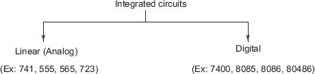
Largely, based on the application and output response, ICs are classified as (1) Linear Integrated Circuits (Linear ICs), and (2) Digital Integrated Circuits (Digital ICs).
Linear ICs accept analog inputs and deliver analog outputs. Examples of linear ICs are given below.
1. Operational Amplifiers (op-amp) 741
2. Timer IC 555
3. Phase Locked Loop IC 565
4. Voltage Regulator IC 723
5. Waveform Generator ICs (8038)
Digital ICs accept input in two discrete voltage levels, viz., logic 0 (zero) or logic 1 (+ 5 V). The output is also discrete in two specific voltage levels only. Due to this, noise immunity is better in digital circuits, compared to analog circuits. The noise signal is analog in nature and it also gets processed along with input in analog ICs and (linear ICs), unlike in digital ICs. Examples of digital ICs are given below.
1. Logic Gates 7400, 7404
2. Multiplexers
3. Microprocessor: 8085, 8086, 80486
Classification of ICs is as shown in Fig. 1.1.
1.2 OPERATIONAL AMPLIFIERS
The credit of desiging internal circuit using vacuum tubes goes to George Philbrick. This was in 1948. Originally, operational amplifiers were meant for analog computers to perform mathematical operations like integration, summation, inversion, and so on. The internal circuit is a differential amplifier and cascaded stages and hence the name, operational amplifier. These are also abbreviated as op-amp and popularly called by that name. The op-amp internal circuit design was further improved by replacing some BJTs with Junction Field Effect Transistors (JFETs).
JFETs at the input stage of the op-amp draw very little current. The input can be varied between supply limits because the supply voltage will not fall as very less current is drawn. MOS transistors in the output circuit will also allow voltage to swing closer to supply limits. As both BJTs and JFETs are used, these are called as BiFET op-amps, LF 356, CA 3130 are of this type. With the development of technology, two op-amps sharing the same Vcc have also been fabricated. These are known as Dual op-amp ICs. Similarly four opamps in the same package of pins have also been fabricated. These are called Quad op-amps: LM 358 is a Dual op-amp, and LM 324 is a Quad op-amp.
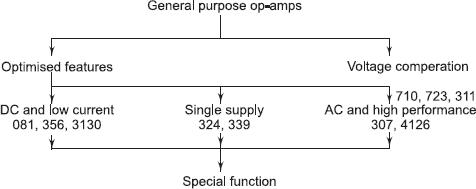
1.3 CLASSIFICATION OF OPERATIONAL AMPLIFIERS
Based on their application and features, op-amps are classified as shown in Fig. 1.2.
Fig. 1.2 Classification of ICs Based on Features
Some of the special function op-amps are:
1. Video/Audio ICs
2. Instrumentation applications
3. Sonar send/receive modules
4. Communication ICs
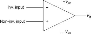
1.4 SYMBOL
The symbol for operational amplifiers is shown in Fig. 1.3.
The internal circuit of an op-amp consists of a differential amplifier to get high Common Mode Rejection Ratio (CMRR) and reduce the effect of noise. Output stage is designed to deliver output power and provide impedance matching.
Fig. 1.3 Symbol for Operational Amplifier
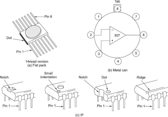
1.4.1 Package
Op-amps are available in three commonly used packages—TO-5 (Metal can), Dual-in-Line Package (DIP), and ceramic flat package. These are shown in Fig. 1.4.
Fig. 1.4 IC Packages Used for Operational Amplifiers
The package of the IC is denoted by a code as follows.
D: Plastic Dual-in-Line Package
J: Ceramic
N, P: Plastic; Dual-in-Line, for insertion into sockets