booksbooks


booksbooks
Practical
and Projects with Arduino, ESP32, and RP2040


Josef Bernhardt


●
Josef Bernhardt
● This is an Elektor Publication. Elektor is the media brand of Elektor International Media B.V. PO Box 11, NL-6114-ZG Susteren, The Netherlands Phone: +31 46 4389444
● All rights reserved. No part of this book may be reproduced in any material form, including photocopying, or storing in any medium by electronic means and whether or not transiently or incidentally to some other use of this publication, without the written permission of the copyright holder except in accordance with the provisions of the Copyright Designs and Patents Act 1988 or under the terms of a licence issued by the Copyright Licencing Agency Ltd., 90 Tottenham Court Road, London, England W1P 9HE. Applications for the copyright holder's permission to reproduce any part of the publication should be addressed to the publishers.
● Declaration
The author and publisher have made every effort to ensure the accuracy of the information contained in this book. They do not assume, or hereby disclaim, any liability to any party for any loss or damage caused by errors or omissions in this book, whether such errors or omissions result from negligence, accident, or any other cause.
● ISBN 978-3-89576-660-2 Print
ISBN 978-3-89576-661-9 eBook
● © Copyright 2025 Elektor International Media www.elektor.com
Editor: Ferdinand te Walvaart
Prepress Production: D-Vision, Julian van den Berg
Printers: Ipskamp, Enschede, The Netherlands
Elektor is the world's leading source of essential technical information and electronics products for pro engineers, electronics designers, and the companies seeking to engage them. Each day, our international team develops and delivers high-quality content - via a variety of media channels (including magazines, video, digital media, and social media) in several languages - relating to electronics design and DIY electronics. www.elektormagazine.com
This book is written for students and electronics enthusiasts interested in practical applications of control engineering. The aim of this book is to teach the fundamentals of control engineering, with a special focus on Fuzzy Logic control systems, and to illustrate these concepts through various practical examples.
In particular, the basics of sensors and linearization are presented in an easily understandable manner, providing a solid foundation for acquiring sensor data. Furthermore, we offer detailed information and examples on controlling different actuators, demonstrating how you can build your own projects.
The book is supplemented with numerous examples and describes real-world applications of control engineering, all implemented on the Arduino platform. This approach allows readers to gain hands-on experience and apply what they have learned directly in practice.
In addition to covering the basics of the Arduino Uno, we also delve into the use of the powerful ESP32 to give you a comprehensive insight into the world of microcontrollers. You will be guided step-by-step through applications for temperature control using Fuzzy Logic, and learn how to control motors, both in terms of speed and position.
The book concludes with chapters on sliding mode controllers, the basics of neural networks, and controllers for grid feed-in, all complemented with practical examples.
We hope this book not only provides enjoyment while reading but also assists you in successfully implementing your own projects. We wish you much fun and success with this book and your future projects!
Finally, we would like to thank everyone who supported us, repeatedly checked details, read the manuscript, provided feedback, allowed us to quote their comments, and helped with editing, proofreading, and design.
Josef Bernhardt
Arduino is an open-source platform for electronics projects that combines hardware and software. It is user-friendly and suitable for both beginners and experienced developers. There is a wide variety of Arduino boards, sensors, and components to choose from.
The name Arduino originates from a bar in the town of Ivrea, Italy, where in 2005, students Massimo Banzi, David Cuartielles, Tom Igoe, Gianluca Martino, and David Mellis conceived the idea of developing a programmable board for prototyping. Arduino was quickly released as an open-source platform, which led to the founding of the Arduino company in 2009. The company supports the production and distribution of the boards and continually develops new products.
With Arduino boards, projects can be realized in various fields, such as robotics and industrial control systems. For programming the hardware platform, the Arduino IDE is used, which allows users to write, test, and upload programs.
The IDE is based on C/C++ and makes it easier for beginners to get started by offering numerous libraries and example codes. Arduino provides endless possibilities for creativity and innovation.
In this book on control engineering, the focus is mainly on the Arduino UNO, Arduino Nano, and the ESP32 from Espressif. The Raspberry RP2040 is also of great interest for more complex projects.
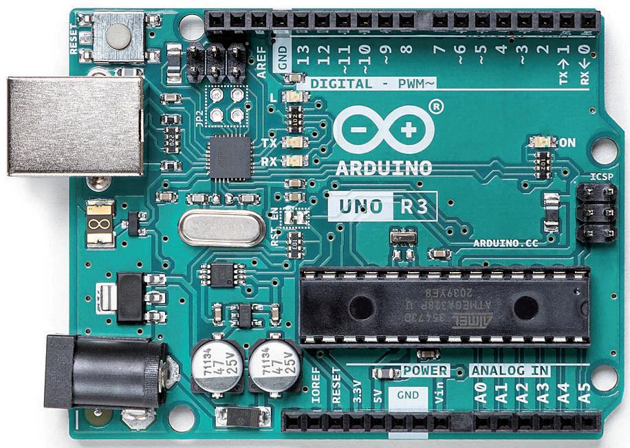
The Arduino UNO is one of the most popular Arduino boards and is based on the ATmega328P microcontroller. It offers numerous digital and analog pins, as well as features like analog/ digital converters, PWM outputs, and serial communication. The UNO is easy to use and has a large developer community, making it ideal for control engineering. Programming is done via the Arduino IDE using C code. With the UNO, we can control sensors, heaters, motors, LEDs, and other components, and build high-quality controllers. Its functionality can be extended with expansion boards, such as displays, network connections, or wireless communication. The UNO is widely used in educational and hobby projects, as well as in professional applications for prototyping and rapid development.
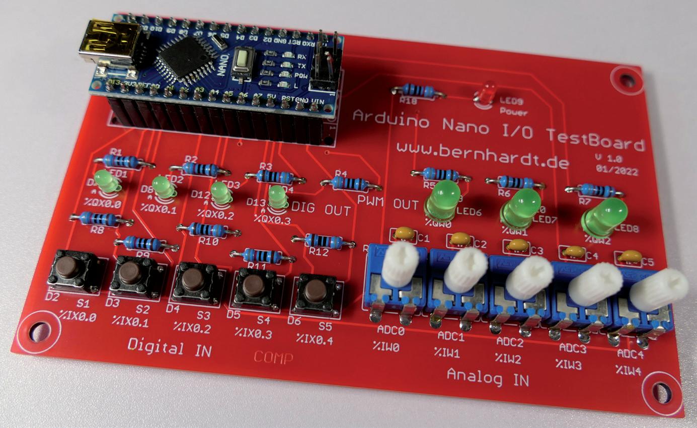
The Arduino Nano is highly suitable for electronics projects due to its compact form factor and is also based on the ATmega328P microcontroller. It offers similar features to the Arduino UNO but in a smaller size, making it ideal for space-constrained projects. The Nano has 14 digital I/O pins, 8 analog inputs, and supports serial communication as well as PWM outputs. Due to its small size and flexibility, the Arduino Nano is often used in portable and space-critical applications.

Features and Specifications of the CPU
• Microcontroller: Atmel / Microchip ATmega328P
• Operating Voltage: 5 Volts
• Input Voltage (recommended): 7-12 Volts
• Digital I/O Pins: 14 (6 of which support PWM)
• Analog Input Pins: 6 with 10-bit resolution
• Flash Memory: 32 KB (0.5 KB reserved for the bootloader)
• SRAM: 2 KB
• EEPROM: 1 KB
• Clock Frequency: 16 MHz
D2
D3
D4
D5
D6
D7
D8
D9
D10
D11
D12
D 13
ADC0
ADC1
ADC2
ADC3
ADC4
Button S1
Button S2
Button S3
Button S4
Button S5
LED 1
LED 2
Description
Digital Input active High
Digital Input active High
Digital Input active High
Digital Input active High
Digital Input active High
Digital Output
Digital Output
LED 6 PWM Output
LED 7 PWM Output
LED 8 PWM Output
LED 3
LED 4
Poti R13
Poti R14
Poti R15
Poti R16
Poti R17
Digital Output
Digital Output
Analog Input
Analog Input
Analog Input
Analog Input
Analog Input
Table 1.1: Pin Assignment Arduino Nano test board.
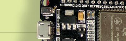
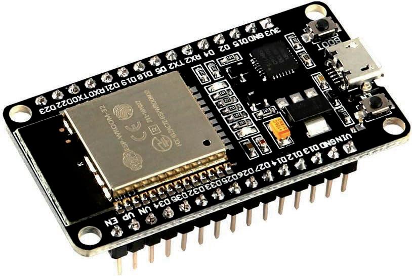
The ESP32 from Espressif is a powerful development board based on the ESP32 microcontroller. It features integrated Wi-Fi and Bluetooth, making it ideal for IoT applications. Programming is also done through the Arduino IDE, which can be downloaded from the official Arduino website [LINK1]. After installing the ESP32 board support, we can program the ESP32 using C++ code and access its hardware. The ESP32 has numerous GPIO pins for connecting sensors and actuators, and it can function as both a server and a client in Wi-Fi networks. Additionally, it allows communication with other devices via Bluetooth.
Due to its versatility, the ESP32 is suitable for projects in smart home, robotics, and control engineering. It is also beginner-friendly and benefits from a large developer community and numerous online resources that help with getting started. With the ESP32, we can collect sensor data and display it over Wi-Fi or on a TFT display, as well as control actuators.
Technical Specifications of the ESP32 Microcontroller:
• Processor: Dual-Core Tensilica LX6 with up to 240 Mhz
• Memory:
- RAM: 520 KB SRAM
- ROM: 448 KB
- Flash Memory: Varies by model, typically 4 MB
• Features:
- Wi-Fi: 802.11 b/g/n
- Bluetooth: v4.2 BR/EDR and BLE
• GPIO Pins: 34 pins, versatile for various peripherals
• Communication Interfaces:
- UART: 3 interfaces
- SPI: 4 interfaces
- I2C: 2 interfaces
- I2S: 2 interfaces
- PWM: Up to 16 channels
- DAC: 2 channels
- ADC: Up to 18 channels, 12-bit resolution
• Additional Features:
- Touch Sensors: Up to 10 capacitive touch inputs
- RTC (Real-Time Clock)
- Hardware Acceleration for Encryption: AES, SHA-2, RSA, ECC
• Power Management:
- Various power-saving modes (Light Sleep, Deep Sleep)
- Operating Voltage: 2.2 V – 3.6 V
• Operating Temperature: -40°C to +85°C
• Peripherals:
- Hall Sensor
- Temperature Sensor
• Connectivity: USB, external power supply via battery or rechargeable battery
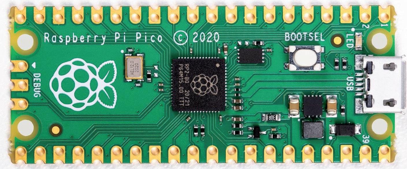
1.4 Raspberry RP2040 controller
The RP2040 is a powerful microcontroller developed by the Raspberry Pi Foundation. It is an affordable microcontroller based on a dual-core architecture, specifically designed for embedded applications. It stands out for its high performance, flexibility, and energy efficiency.
The CPU features a range of functions, including GPIO pins, UART, SPI, and I²C interfaces, as well as a variety of peripheral modules. It also supports programming via USB and includes an integrated USB bootloader, enabling programming and operation without the need for external programming devices.
Features and Specifications:
• Microcontroller: Dual-Core ARM Cortex-M0+ (up to 133 MHz)
• Operating Voltage: 3.3 Volts
• Digital I/O Pins: 30 (26 of which are PWM-capable)
• Analog Input Pins: 4
• Flash Memory: 2 MB (QSPI)
• SRAM: 264 KB
• EEPROM: Not available
• Clock Speed: Up to 133 MHz
The RP2040 is supported by a dedicated developer community that provides a variety of resources, including documentation, tutorials, forums, and example projects. These resources make project development easier and encourage the exchange of knowledge and experiences within the community.
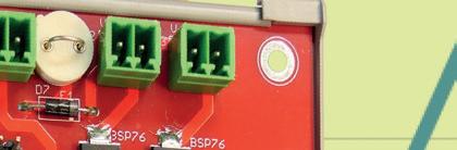
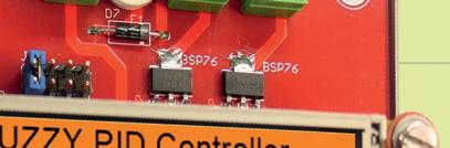
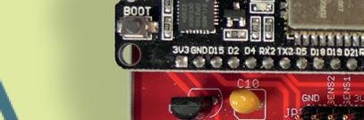
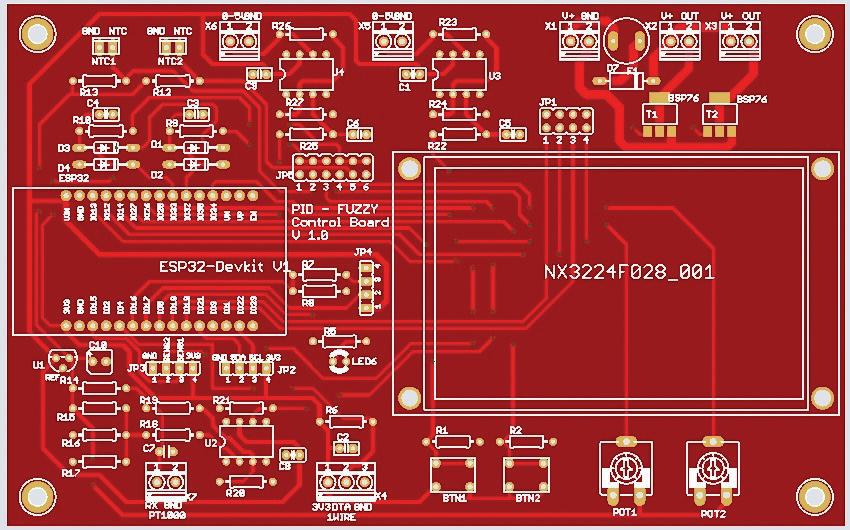
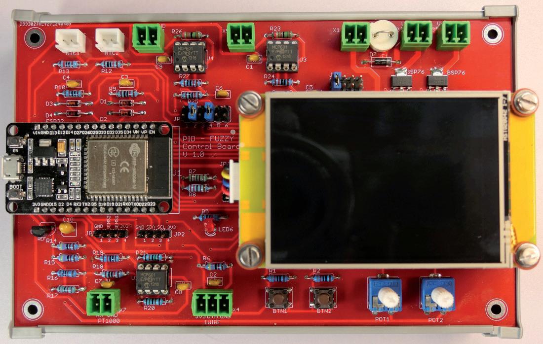
For the program examples in this book, we use a test board specifically designed for control engineering. The "ESP32 Fuzzy PID Controller" board is a versatile platform for precise control and regulation applications. With a wide range of interfaces, it allows seamless integration into numerous applications.
Additional practical applications, such as using it as a PLC or Modbus TCP I/O module, as well as protocols like MQTT or web applications with WebSockets, are always possible.
Input Interfaces:
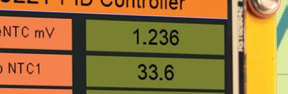
• 2 x NTC 10K: These interfaces enable precise temperature change measurements using NTC temperature sensors.
• 1 x PT1000: The PT1000 interface allows for accurate temperature readings using PT1000 temperature sensors.
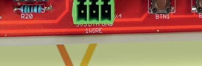
• 1 x OneWire for DS18B20 or DHT11 / DHT22: This flexible interface supports the use of DS18B20 temperature sensors or DHT11/DHT22 humidity sensors for reliable environmental monitoring.
• 2 x Buttons: Two buttons provide an easy user interface for controlling and configuring the system.
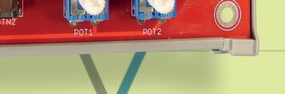
• 2x Potentiometers: Two potentiometers allow manual adjustment of parameters or thresholds for fine-tuned control.
• 2 x Sense Lines for Motor Speed and Position Monitoring: These interfaces allow for precise measurement of motor speed and position for accurate control.
Output Interfaces:
• 2x 24V 1A for Motor or Relays, optionally also for PWM: These outputs offer flexibility for controlling motors or relays, optionally via PWM signals for precise power control.
• 2 x Analog Outputs 0 to 5 Volts: Two analog outputs enable the generation of voltage signals in the range of 0 to 5 volts for driving external devices.
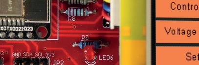
• 1 x 4-pin I2C Connection for Expansion: The I2C interface allows easy integration of expansion modules for additional functions or interfaces.
• 1 x UART2 TTL for Nextion Display NX3224F028 (2.8 inches): The Nextion display provides a clear, user-friendly interface for displaying data and, with touch functionality, allows interaction with the system.
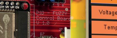
With its powerful ESP32 chip and a wide range of interfaces, the ESP32 Fuzzy PID Controller Board offers a robust and flexible solution for a variety of applications, from temperature control to position monitoring. A complete layout and schematic diagrams can be found in the appendix.
Pin Assignment of the ESP32 from the Test Board:
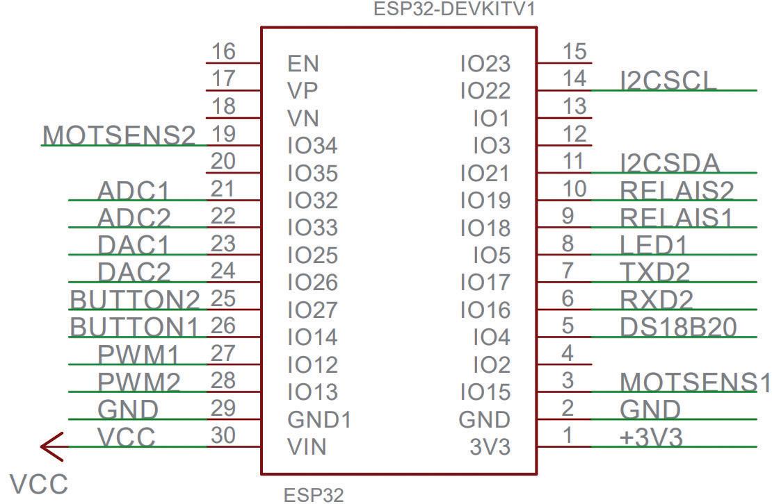
BUTTON2 25 IO27 Button 2 Input MOTSENS1 3
Motor Sensor 1 Input MOTSENS2 19
Motor Sensor 2 Input
I2CSDA 11 IO21 I2C Data
I2CSCL 14
RXD2 6
I2C Clock
UART RX Input TXD2 7
UART TX Output DS18B20 5
Activation for relays 2
Table 1.2: Pin assignment for the GPIO ESP32 module
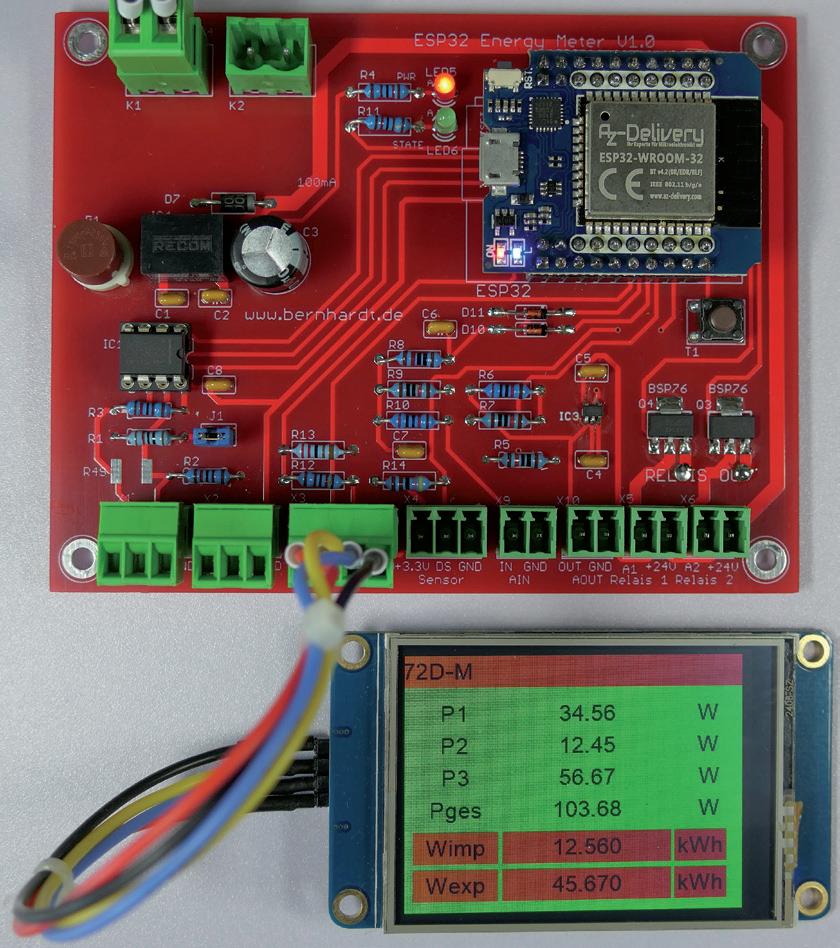
1.6 ESP32 Modbus RTU controller board
This board is also suitable for capturing measurement values such as current, voltage, and power, and is known as the ESP32BoardModbusRTUControl board. Schematic, diagrams and layouts are included in the appendix.
The ESP32 board is designed to read energy meters such as the Shelly 3EM via Wi-Fi, as well as the Eastron SDM series (compatible with Controlin) and KBR multimess 96 via RS485 (Modbus RTU). A functioning Wi-Fi connection is required for operation. The data from the meters is displayed on the built-in screen and sent to a server every second in JSON format via HTTP, where it is stored. XML format is also possible. The controller software was developed using the Arduino IDE. Possible protocols include HTTP POST and GET, MQTT, REST, Modbus TCP Server, and other TCP/IP protocols.
The board also allows for the control of inverters to achieve zero injection using the power data.
Technical Specifications:
• CPU: ESP32 by Tensilica
• Power Supply: 12-24 Volts DC
• Interfaces:
- RS485
- Wi-Fi 2.4 GHz and Bluetooth
- UART RX TX for 5V Nextion Display 2.4-inch NX3224T024
• Outputs:
- 2 x 24V DC outputs for relays or contactors
• Inputs/Outputs:
- 1 x 10V analog input (expandable to 0-20V or 0-50V)
- 1 x 10V analog output (or 0-5V)
- 1 x OneWire for DS18B20 temperature sensor
Information on the Software of the ESP32 Module:
The module automatically connects to the Wi-Fi network after power-on, using the SSID and password that are stored in the program. If no Wi-Fi network is available, an access point must be installed.
Listing: ESP32_SDM_EnergyMeter.ino
// Wlan Parameter
char* ssid = "FRITZ!Box 7590 RI";
char* password = "52x6165x80538x77x967";
You then have the option of either reading the Shelly 3EM via WLAN or the Eastron SDM or Controlin meter via Modbus RTU.
Here is an example of querying the Shelly 3EM every second:
// Shelly 3 em
String serverName1 = "http://192.168.178.40/emeter/0"; /// Answer from Shelly {"power":15.32,"pf":0.25,"current":0.27,"voltage":226.96,"is_ valid":true,"total":2.0,"total_returned":0.0}
String serverName2 = "http://192.168.178.40/emeter/1"; // Answer from Shelly {"power":49.16,"pf":0.78,"current":0.27,"voltage":225.98,"is_ valid":true,"total":5.9,"total_returned":0.0}
String serverName3 = "http://192.168.178.40/emeter/2"; /// Answer from Shelly {"power":11.56,"pf":0.40,"current":0.13,"voltage":227.10,"is_ valid":true,"total":2.0,"total_returned":0.0}
The data is converted from JSON format to float values, and the total performance is calculated.
The current timestamp is then queried from a time server and the data is sent to the Firebase or Postgre SQL Server.
An RS485 energy meter is connected via the UART1 and the following library:
https://github.com/reaper7/SDM_Energy_Meter
// Nextion Display
#define RXD2 16
#define TXD2 17
// RS485 Modbus RTU
#define RXD1 19
#define TXD1 18
#define REDE1 26
// Init RS485 Modbus RTU
SDM sdm(Serial1, SDM_UART_BAUD, REDE1, SERIAL_8N1, RXD1, TXD1);
The following Modbus registers are read out:
PowerArr[0] = sdm.readVal(SDM_PHASE_1_VOLTAGE);
PowerArr[1] = sdm.readVal(SDM_PHASE_1_CURRENT);
PowerArr[2] = sdm.readVal(SDM_PHASE_1_POWER);
PowerArr[3] = sdm.readVal(SDM_FREQUENCY);
PowerArr[4] = sdm.readVal(SDM_IMPORT_ACTIVE_ENERGY);
PowerArr[5] = sdm.readVal(SDM_EXPORT_ACTIVE_ENERGY);
For Modbus RTU meters from other manufacturers, the registers must be adapted and tests carried out.
The appendix also contains circuit diagrams and layouts for an Arduino Nano board and an Arduino Mega board with four digital and four analogue lines.
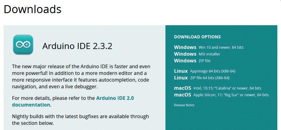
1.7 Programming the Arduino boards
A development environment is available for programming the boards, which can be downloaded for free from the Arduino website.
The software is available for Windows, Linux, and macOS.
The website address is: https://www.arduino.cc/en/software
After installing the IDE, missing boards such as the ESP32 can be installed through the Board Manager settings. A list of installable Arduino boards can be found here:
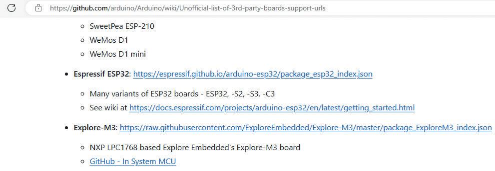
Figure 1.11: ESP32 Github website
Unofficial list of 3rd party boards support urls · arduino/Arduino Wiki · GitHub
1. Open the Arduino IDE 2.3.2 on your computer.
2. Go to 'Tools' > 'Board' > 'Board Manager'.
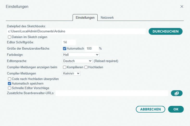
1.12: Settings in the Arduino IDE
3. Enter 'ESP32' in the search bar at the top right of the board manager and press Enter.
4. A list of available ESP32 boards should appear. Select the ESP32 board you want to use (e.g., 'ESP32 Dev Module').
5. Click on the Install button next to the ESP32 board to install the board support.
6. Wait until the installation is complete. This will take a few minutes.
7. Once the installation is complete, you can select the ESP32 board from the list of available boards under 'Tools' > 'Board'.
After the ESP32 board is successfully installed, you can use it like any other board in the Arduino IDE and write and upload programs for the ESP32.
1.8 The Nextion graphic display
To display the measurement data in the examples, we use a 2.8 inch graphic display NX3224F028_001 from Nextion. The big advantage over other displays, such as those with an IL9341 graphics chip, is the control with the UART via the RX/TX lines and, above all, the simple programming.
A free development environment for the PC is available from Nextion for programming the display. This can be used to design the user interface for the display on the PC. Many graphic elements such as buttons, text boxes, labels etc. are available.
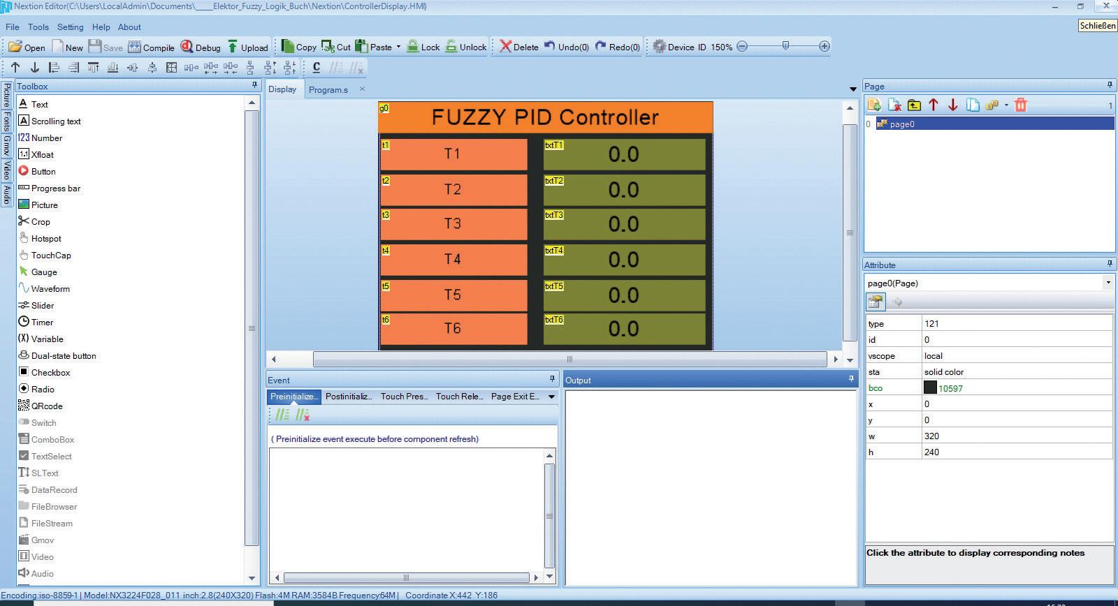
Also included in the IDE is a debug function and an option to transfer the TFT file to the display. A simple USB-UART module can be used for this (upload).
A second option is to save the generated TFT file to a micro-SD card. This menu item can be found under 'File' 'TFT file output.' The SD card is then inserted into the SD slot of the display and voltage is applied. The program is now transferred from the display to the microcontroller. The card is then removed again. This saves you having to plug and unplug the display when it is mounted on the ESP32 board.
The ControllerDisplay.HMI and ControllerDisplay.tft files are stored in the 'Nextion' directory.
You can find lots more information and tutorials on the Nextion website.
1.9 Test software for the ESP32 board
This program is for initializing the hardware. The timer is initialized to 10 ms using the Ticker.h library. Then the two UART for the USB connection to the PC and UART2 for the Nextion display. In the timer the variable counter10ms is increased, if the value 100 is reached it sets a flag oneSecond which is queried in the loop(). This provides an exact time cycle for the output of the second counter. The program can be used as a 'basic framework' for further programs.
Listing 1: Arduino_UART2_NextionDisplay.ino
//---------------------------------------------------------------------
//
// Arduino Testsoftware
// ==================== //
// Testprogramm for Arduino ESP32 PID Fuzzy Control Board
// 10ms Timer Interrupt Function
// Init UART2 for Nextion Display
// Display seconds on Display NX3224F028_001
//
// Date: 28/04/2024
// Author: Josef Bernhardt
// Hardware: Arduino (ESPRESSIF) ESP32
//
// File: Arduino_UART2_NextionDisplay.ino
//---------------------------------------------------------------------
#include <Arduino.h>
#include <Ticker.h>
int LED_BUILTIN = 2;
// ESP32 UART 2 Pins
#define RXD2 16
#define TXD2 17
// I2C Pins
#define I2CSCL 22
#define I2cSDA 21
// ESP32 ADC Pins
#define ADC1 32
#define ADC2 33
// Motor Sensor Pins
#define MOTSENS1 15
#define MOTSENS2 34
// Buttons
#define BTN1 14
#define BTN2 27
// Relay and Mosfet (BSP76) Pins
#define RELAIS1 18
#define RELAIS2 19
// LED1
#define LED1 5
// PWM1 and PWM2 Pins
#define PWM1 12
#define PWM2 13
// DAC Outputs 0..5V
#define DAC1 25
#define DAC2 26
// One Wire
#define DS18B20 4
In this code, a `ticker` object called `timer` is used to call a timer function every 10 milliseconds. A counter (`counter10ms`) is incremented by 1 with each call, and when this counter reaches the value 100, which corresponds to one second, it is reset. The variable `OneSecond` is set to `true` to indicate that one second has elapsed. The second counter (`CounterSeconds`) is used in loop() to call the output every second. OneSecond is set to false for the next run.
// Define 10ms Period const unsigned long timerInterval = 10;
// Ticker-Objekt for the Timer-Funktion Ticker timer;
// Counter int counter10ms=0;
// When 1 second is elapsed bool OneSecond = false;
// Counter for seconds int CounterSeconds = 0;
// Timer-Funktion
// Called every 10 ms void timerCallback()
{ // Inc 10ms Counter counter10ms++;
// If one Second if(counter10ms==100) { counter10ms = 0;
// One Second OneSecond = true; } }
This function sends data to a Nextion display to update the text of a textbox. It uses the serial interface `Serial2` to send a command that selects the textbox (`textbox`) and inserts the new text (`float`). The text is enclosed in quotes and the command is terminated with three terminating bytes (`0xFF`) to mark the end of the command. This enables the Nextion display to show the text correctly.
// Sends Data to Nextion Display in a textbox void Nextion_Send_Text_to_Textbox(char *textbox,String sfloat)
{
Serial2.write(textbox);
Serial2.write(".txt=\"");
Serial2.print(sfloat);
Serial2.write("\"");
Serial2.write(0xFF);
Serial2.write(0xFF);
Serial2.write(0xFF);
}
// Initializing the hardware void setup()
{
// Init USB UART
Serial.begin(115200); // Nextion Display // TFTSerial.begin(9600);
Serial2.begin(9600, SERIAL_8N1, RXD2, TXD2);
// Init Hardware
pinMode(LED_BUILTIN, OUTPUT); pinMode(LED1, OUTPUT); pinMode(RELAIS1, OUTPUT); pinMode(RELAIS2, OUTPUT); pinMode(BTN1, INPUT); pinMode(BTN2, INPUT);
// Clear Textboxes
Nextion_Send_Text_to_Textbox("t1","Counter"); Nextion_Send_Text_to_Textbox("t2"," "); Nextion_Send_Text_to_Textbox("t3"," "); Nextion_Send_Text_to_Textbox("t4"," "); Nextion_Send_Text_to_Textbox("t5"," "); Nextion_Send_Text_to_Textbox("t6"," ");
Nextion_Send_Text_to_Textbox("txtT2"," ");
Nextion_Send_Text_to_Textbox("txtT3"," "); Nextion_Send_Text_to_Textbox("txtT4"," ");
Nextion_Send_Text_to_Textbox("txtT5"," ");
Nextion_Send_Text_to_Textbox("txtT6"," ");
// Init Timer with 10ms timer.attach_ms(timerInterval, timerCallback); }
The `loop()` function checks whether a second has elapsed based on the `OneSecond` variable. If this is the case, `OneSecond` is reset to `false` and the `CounterSeconds` counter is incremented by one. The new value of `CounterSeconds` is sent to the serial monitor via the serial interface and sent to a text box on the Nextion display. In addition, the status of two LEDs is switched: the internal LED and another LED (`LED1`). The code thus ensures regular updates and visual feedback via the LEDs.
void loop()
{
// Check if one second has passed if (OneSecond) {
// Reset the boolean variable OneSecond
OneSecond = false; CounterSeconds++;
// Sends variable to USB UART and Seriell Monitor
Serial.print("Timer: ");
Serial.println(CounterSeconds);
// Sends variable to display
Nextion_Send_Text_to_Textbox("txtT1",String(CounterSeconds));
// Switching LED
digitalWrite(LED_BUILTIN,!digitalRead(LED_BUILTIN));
digitalWrite(LED1,!digitalRead(LED1));
}
// Additional code for the main loop }
1.10 Program example with the ESP32
In the next program, the buttons are queried. The button on BTN1 is queried and debounced with the function read_btn1(). In the timer function, which is called every 10 ms, the pushbutton at BTN2 is read. If BTN2 is at low level three times in succession, i.e., 30 ms, the key_press variable is set to True. The key press is queried with the get_key() function. When the information is pressed, the values of the state variables state1 or state2 are changed to save the current state and then switch the RELAIS1 and RELAIS2 outputs. Press once to switch on, press again to switch off. These functions will be used later to set the setpoint of controllers.
Immerse yourself in the fascinating world of control engineering with Arduino and ESP32! This book o ers you a practical introduction to classic and modern control methods, including PID controllers, fuzzy logic, and sliding-mode controllers.
In the first part, you will learn the basics of the popular Arduino controllers, such as the Arduino UNO and the ESP32, as well as the integration of sensors for temperature and pH measurement (NTC, PT100, PT1000, and pH sensor). You will learn how to use these sensors in various projects and how to visualize data on a Nextion TFT display.
The course continues with an introduction to actuators such as MOSFET switches, H-bridges, and solid-state relays, which are used to control motors and actuators. You will learn to analyze and model controlled systems, including PT1 and PT2 control.
The book focuses on the implementation of fuzzy and PID controllers for controlling temperature and DC motors. Both the Arduino UNO and the ESP32 are used. The sliding-mode controller is also introduced.
In the second-to-last chapter, you will explore the basics of neural networks and learn how machine learning can be used on an Arduino.
In the last chapter, there is a practical example of a fuzzy controller for feeding electricity into the household grid.

Josef Bernhardt discovered his passion for electronics at a young age. He took his first steps in programming in the 1980s with the Apple II and the IBM PC. With over 30 years of experience in electronics development at the University of Regensburg, Josef Bernhardt is an expert in his field. There, he worked in both electronics and software development. Through his involvement in his own SMD production, he successfully realizes electronics projects for customers. His passion for electronics and programming, as well as his constant interest in new technologies, have accompanied him since his youth and have characterized his entire life.
This book is the perfect choice for engineers, students, and electronics engineers who want to expand their projects with innovative control techniques. Elektor International Media www.elektor.com