Construction and Sustainability Design Studio- Fall 2020
Polytechnic University of Milan
Professors: Elena Lucchi, Matteo Scaltritti
Wellness Bridge
Ambulatory Surgery Facility
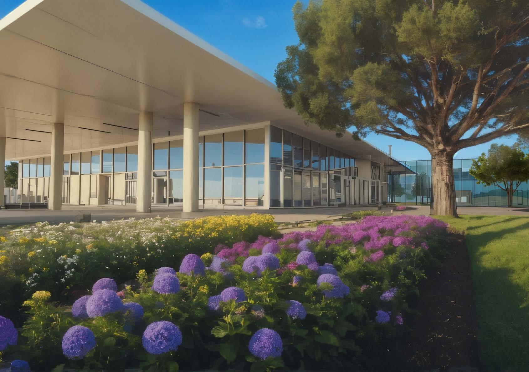
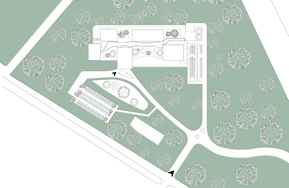
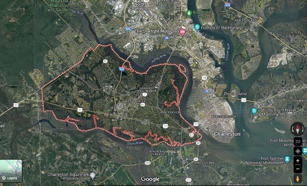
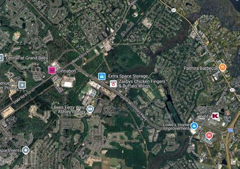
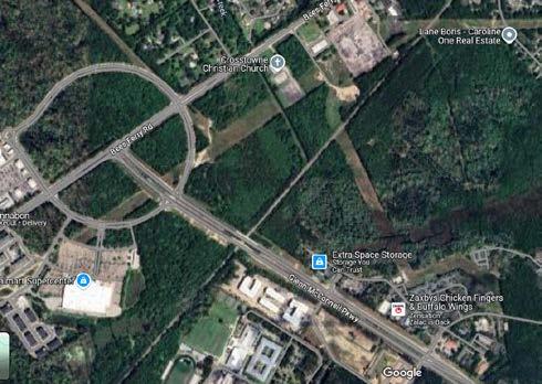
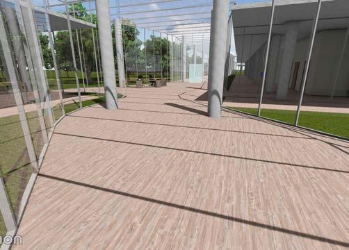
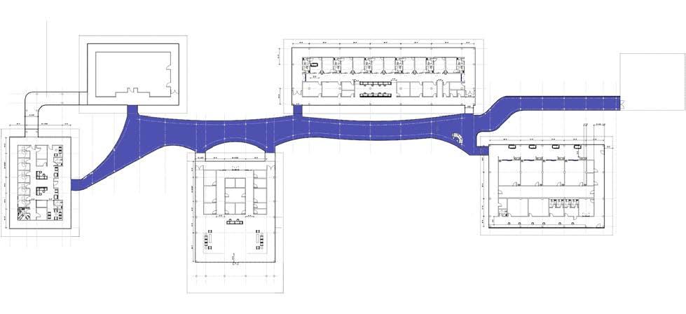
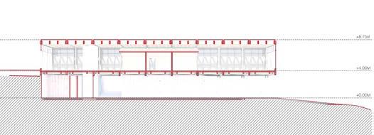
Positioned on the outskirts of Charleston, the site takes advantage of an undeveloped wooded area near suburban neighborhoods and shopping centers. This location was selected for its convenient accessibility to a dense population while also providing a serene greenfield environment. The open and secluded setting fosters a retreat-like atmosphere. A patient-centric approach prioritizes comfort and experience by incorporating views of surrounding greenery. Outdoor community spaces provide opportunities for relaxation and interaction. Strategic scalability is achieved by planning for future expansion, ensuring the facility can adapt and grow with increasing demand. This goal is achieved by designing separate buildings for each department, connected through a glass corridor belt that enhances accessibility.
PUBLICPARKING
MAINENTRANCE
VIEW OF THE SITE
Departments Connections
The design approach leverages the surrounding greenery by separating each department into its own building, enhancing natural light and views through interior glass corridors within each structure. A connecting glass corridor belt unites all departments, serving as both a functional pathway and a striking architectural feature of the facility.
3D VIEW OF CONNECTION
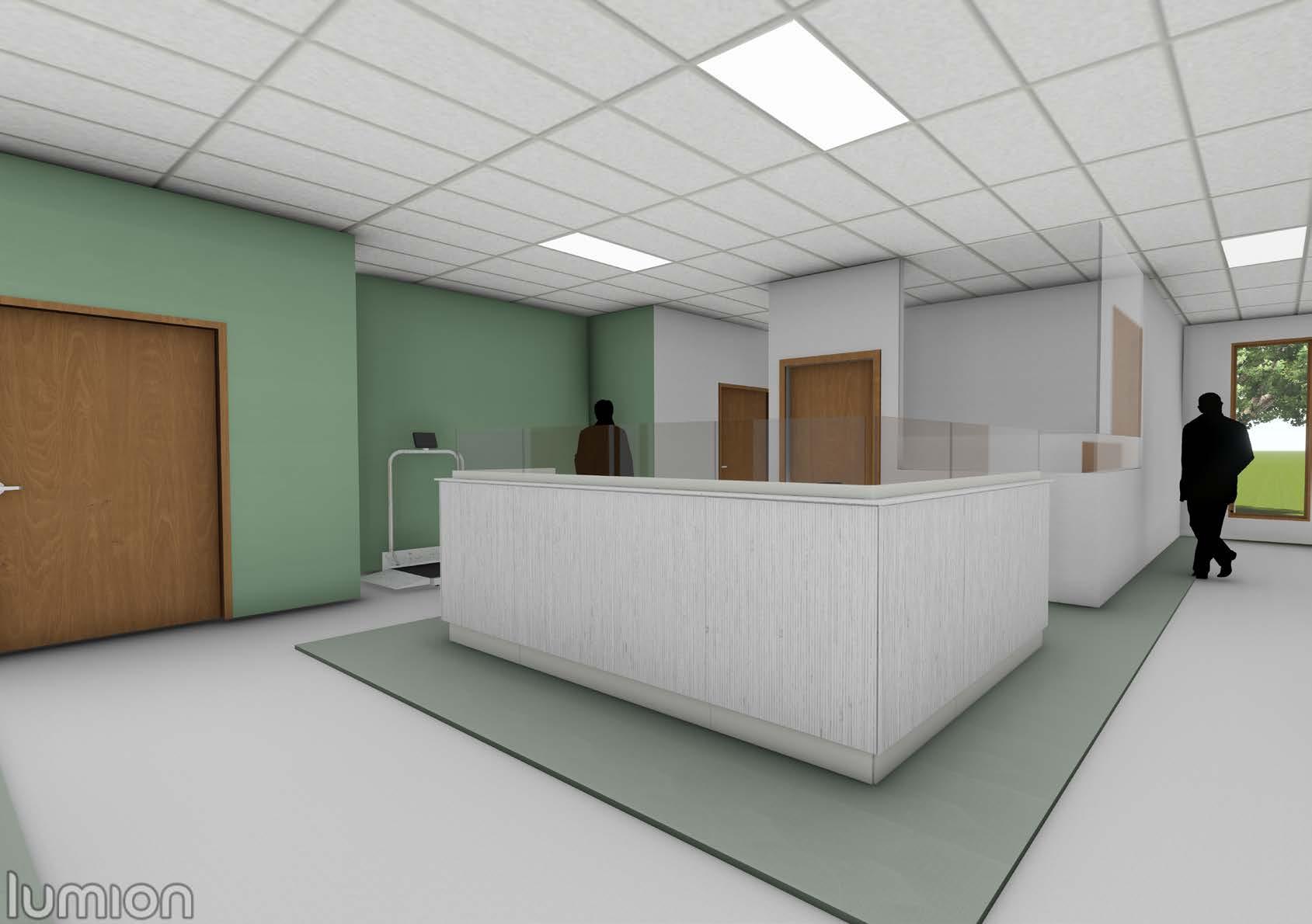
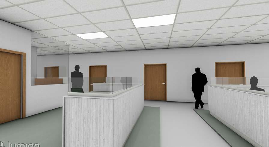
3D VIEW OF NURSE STATION IN PREP/PACU
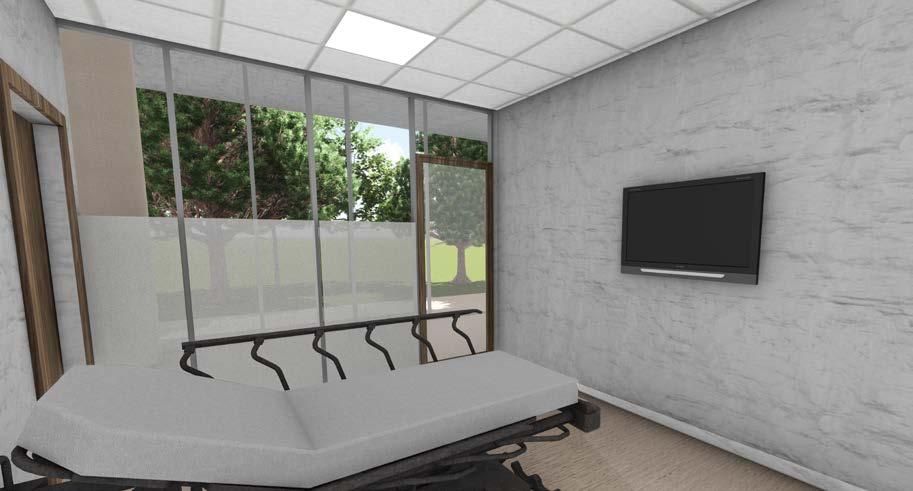
Pre-operative & Post-anesthesia Care Unit
The Prep-Pacu includes 10 patient rooms, each with a private bathroom and observation Windows. The rooms are mirrored and arranged in the most efficient layout for this configuration, with supporting spaces positioned parallel to the patient rooms. The nurse station is centrally located, positioned parallel to the patient rooms to facilitate effective monitoring.
3D VIEW OF PATIENT ROOM IN PREOP/PACU
Surgical Suite
The OR suite consists of four rooms arranged linearly, providing direct access to a central sterile core located between the OR rooms and the supporting areas. The Prep/PACU area and the OR suite, though separate, are connected by a glass corridor, with a control desk strategically located within this space. The OR rooms follow identical furniture arrangements.
SURGICAL SUITE LAYOUT
AXONOMETRIC VIEW
OPERATING ROOM LAYOUT
Healing Horizons
Individual Project
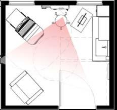
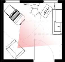
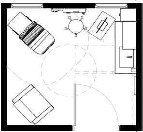
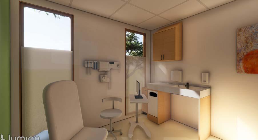
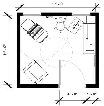
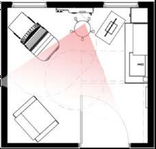
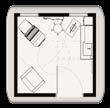
The design process for exam pods begins with FGI requirements for an exam room as an initiative cell. It focuses on two key aspects: ensuring patient privacy and optimizing caregiver workflow. Privacy zoning and strategic placement of elements like the caregiver’s seat, exam table, and sink are central to this process, fostering efficient and private patient care.
Care-Giver Working Zone
Arrangment of
Dynamics between Patient, Caregiver, and Visitor.
Diagnostic Equipment, Sink and Exam Table Patient & Consultation Zone
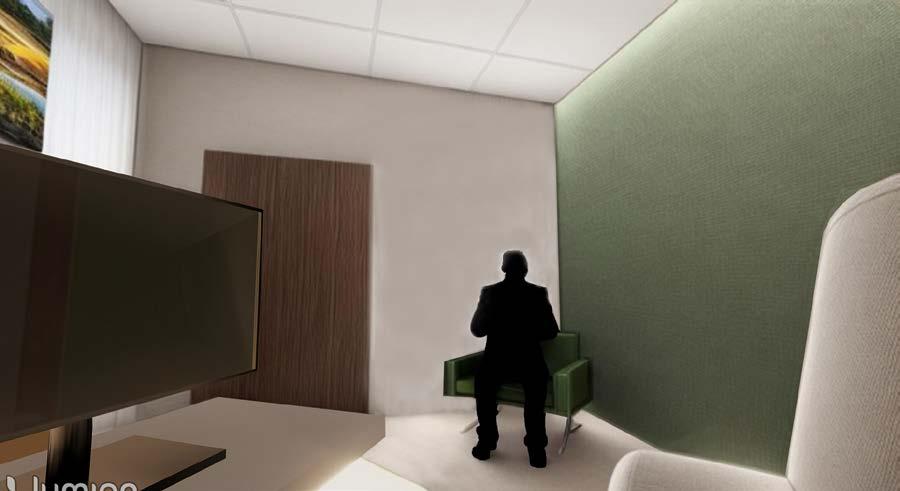
3D VIEW FROM VISITOR SIDE
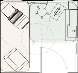
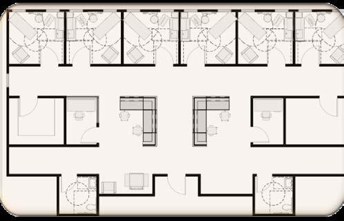
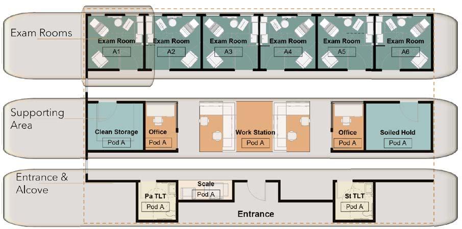
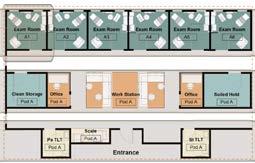
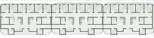
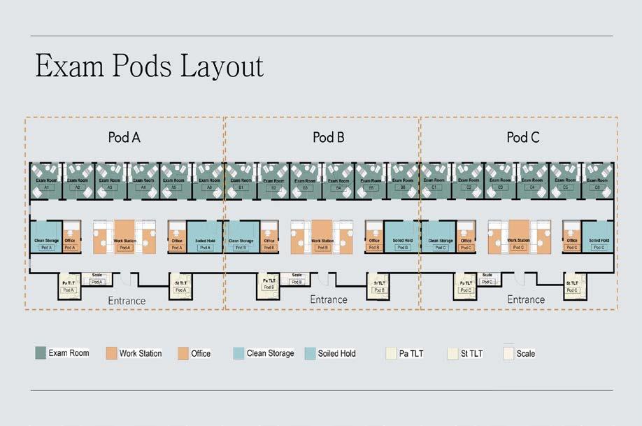
The design process for the exam pod follows a linear layout, incorporating six exam rooms in a sequential fashion. Adjacent to these rooms are parallel lines housing supporting areas and the entrance. Placing the caregiver station at the center grants equal and optimal control over all exam rooms, ensuring seamless management and supervision within the pod’s layout.
EXAM POD LAYOUT
3D VIEW FROM VISITOR SIDE
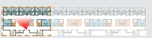
The design process for the exam pods is crafted to enable each pod control over two adjoining exam rooms, fostering efficient use of space. Shared soiled and clean storage areas facilitate collaboration between two agent pods. Emphasizing proximity, every element within the plan is strategically placed for convenience. The entrance, distinguished by a specific color and equipped with a scale, serves as a clear navigational aid for patients, minimizing confusion and offering location awareness.
EXAM PODS LAYOUT
EXAM PODS LAYOUT
VIEW FROM ENTRANCE
Beyond the Border
Group Members: Elaheh Malek Zadeh, Marcelina Piskozub, Kevin Sheldon
Contribution: Original Concept Creator- Developed Project’s Visual Presentations
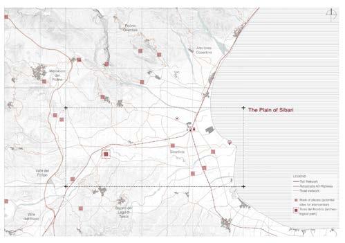
A view for Sibarian territory
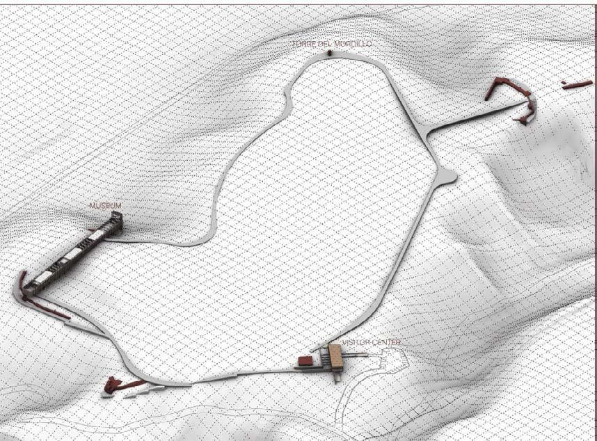
Torre del Mordillo - The Mordillo tower, built around the 11th century by the Normans was probably used as a viewing point, gives its name to a vast archaeological area from the Bronze Age (17th century BC) up to the Hellenistic Age. The site features numerous archaeological findings, including ruined walls and foundations of historic settlements.
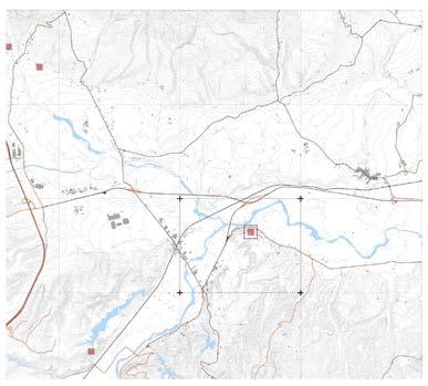
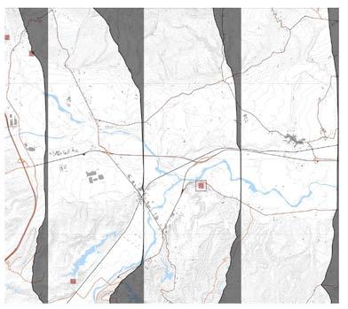
Geographical context of Torre Mordillo
Geographical context of Torre Mordillo
Geographical context of Torre Mordillo
VIEW OF THE SITE
MODEL
The Path:
Creating a Connection Between Boundaries
of the Plateau of Torre del Mordillo
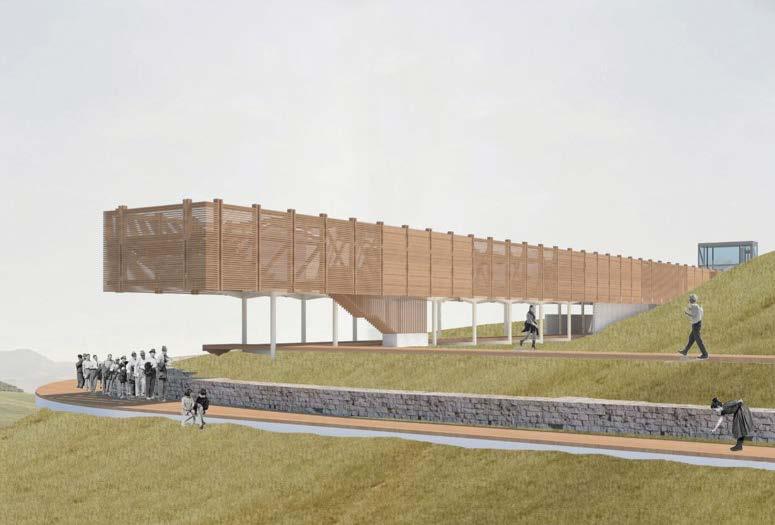
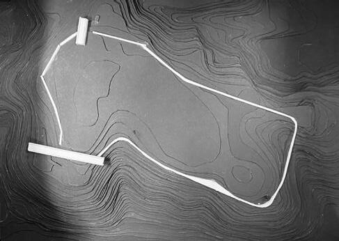
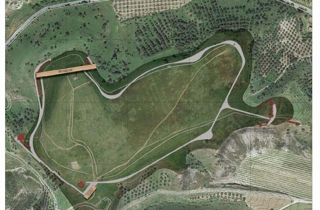
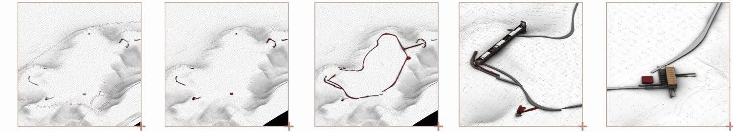
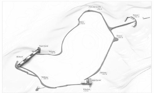
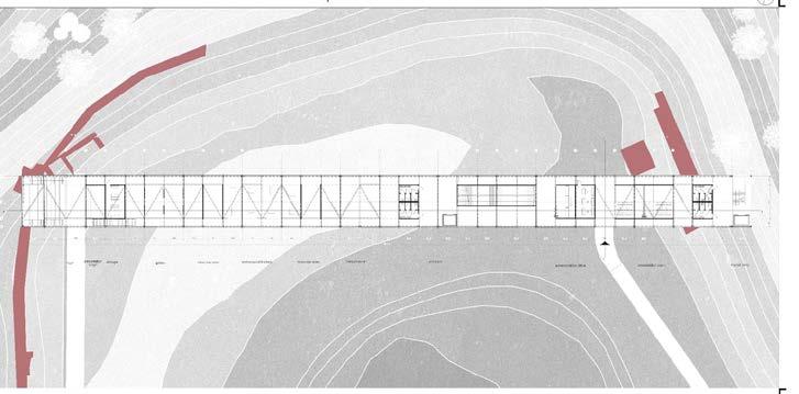
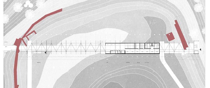
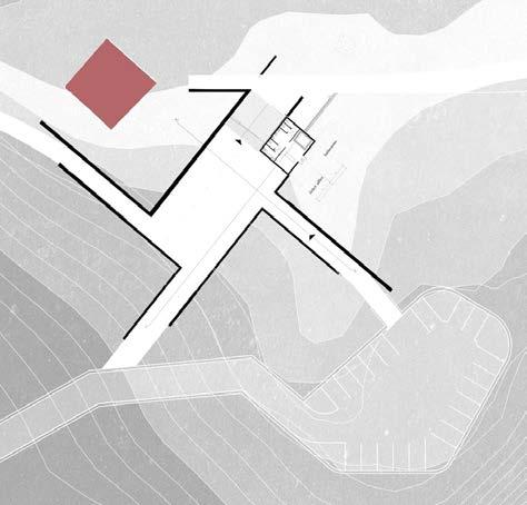
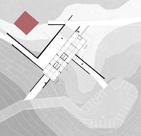
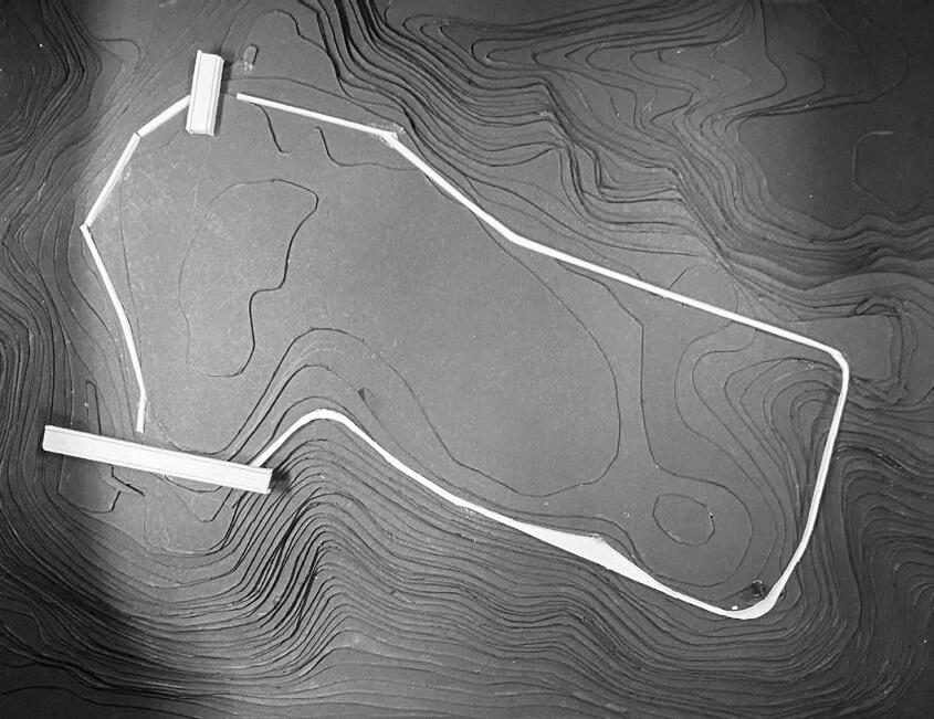
The idea of our project is about connection. The chosen plot is plateau with Torre del Mordillo on the boundary. The place has a touristic potential, due to its location near the pilgrim track, and bike roads. The project is setting boundaries on plateau of Torre del Mordillo. By doing that, we make a border of the site and the exterior of the area. Border emphasise the boundary and make a connection between diffrent parts of plot. Border is highlighted by a pathway that creates way to have a possibility to enjoy the walk and views from plateau. On the road, there are several “stop points’ with different functions, e.g. museum and entrance to the plateau.
ACCESSIBILITY
RUINS
PASSAGE LOOP
The park of Torre Mordillo stands on a hill overlooking plain of Sibari about 1 km from the confluence of the Esaro and Coscile rivers. It is accessible only by private transport or by foot through an existing motorway leading to the entrance of the site.
There are many archeological findings from the site and also ruin walls and foundations of historic settlements. These ruins are pre-dominantely found on the periphery of the site.
Walkable passage follows the landscape and moves along the archeological park connecting the ruins and creating vantage points on top of the hill. The passage forms a border to the site making a clear difference between the inside and out.
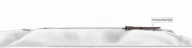
Along the path running around the park, a museum space is introduced as a new intervention space to store and display the findings from the site. Museum volume creates a visual certainty in the context which becomes monumental to the site.
The building acts as portal to the site and it houses a shop, ticket office and toilet facilities. Primary function is to provide ticketing, information, and orientation for the archeological site and about the exhibits in the Museum.
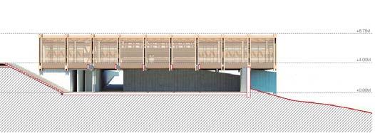
SOUTH WEST AXONOMETRIC VIEW OF THE SITE
MUSEUM
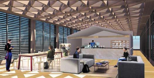
VISITOR CENTER
The Museum
A museum area is added as a new intervention space along the path around the park to house and showcase the site’s discoveries. A visual certainty that becomes monumental to the location is produced by museum volume in the surrounding setting.
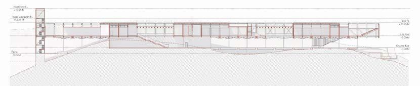
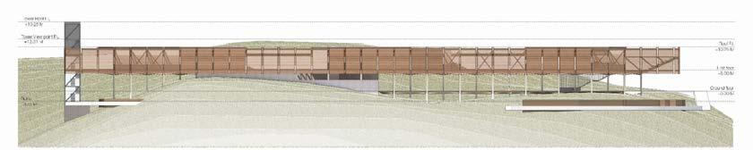
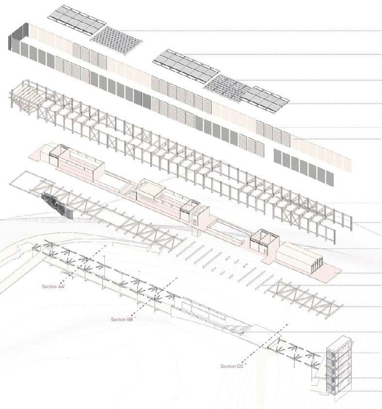
The Museum Structure
A mixed material approach used in the construction of the museum building included concrete foundtion for steel columns, steel baseplate fixed to concrete foundation, and wooden deck flooring.
Secondary roof beams
Wooden shingles fixed on purlins
Steel gutter fixed in between skylight and wooden shingles
Glass skylight fixed on roof with L channels
Triangulad grid CLT wood framework open to sky
Skylight fixed on roof with alumnium chanels
Triangular roof with fixed glazing over it
Wood shingles fixed on top of timber purlines with waterproofing sheet below
Fixed timber louvres
Opaque timber facade
Cross laminated timber column and beam framework
plank facade 150*50
deck flooring
panelled enclosed spaces
deck flooring
Concrete beam support from retaining walls
Cross laminated timber beams
Retailing walls for the sunken part of the building double vertical timber members
Steel webb capital to support the timber framework
300mm Dia steel columns
and glass tower block for vertical
The structure serves as the site’s entrance. The visitor center plays a critical role in welcoming and orienting visitors to the historical site. It has a store, a ticket office, and restrooms. Ticketing, information, and orientation regarding the archeological site and the museum’s displays are the main functions. Visitors can purchase admission tickets, obtain maps and brochures, and receive guidance.
NORTH WEST ELEVATION
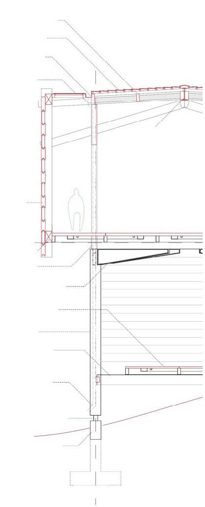
Toughened glass fixed on wooden framed work with spider leg hinges
Triangular grid cross laminated timber fixed with metal brackets supports the glass roof
Aluminum glazing inside with openable shutters
Fixed horizontal timber louvers on the facade to shade the interior
First level of the building with functions-lift, cafe, store, service toilet Timber wood flooring Lift core
Concrete beam support
Domun 12*12
Site ruins Cross laminated timber framed structure integerated shear wall and beams
Concrete retaining walls 200mm thick
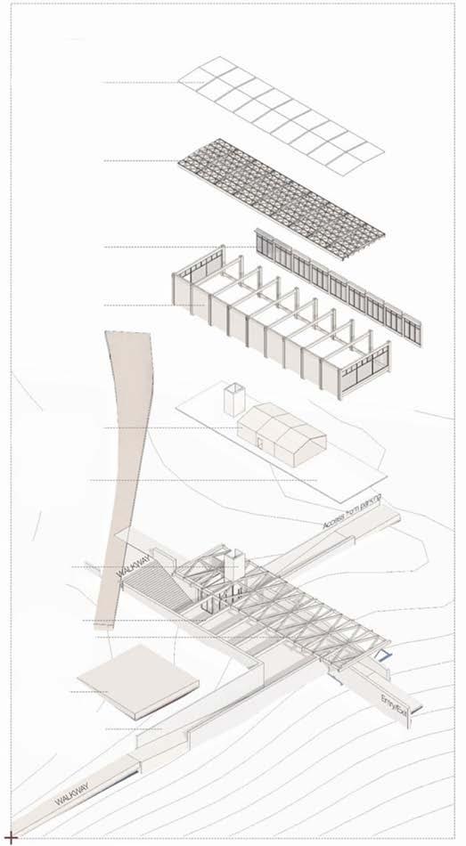
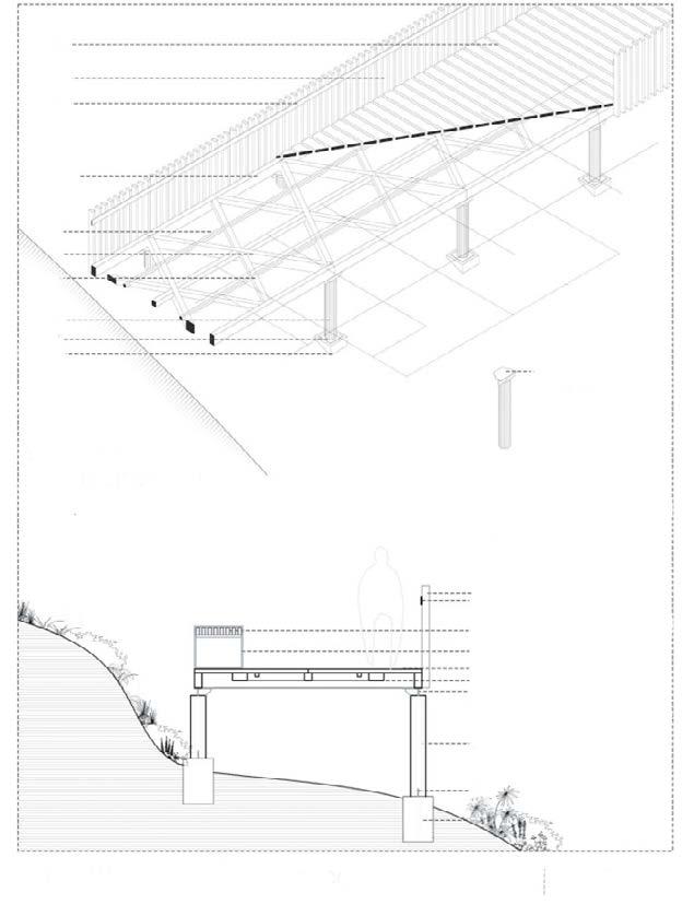
Walkway Passage
1. Steel flat 5mm thick 100mm wide
2.Vertical Timber Guardrail 50*100mm
3.Timber floor deck 100*25mm thick
4.CLT wooden beam 300*100mm thick
5. Tertiary Timber joist to support floor
6. Primary timber beam 100*300mm
7.Secondary timber beam 100*100mm
8. Steel columns 200mm Dia
WALKWAY AXNOMETRIC VIEW
9.Steel baseplate 250*250
10. Concrete foundation
11.Timber seating
12. Baseplate for beams
Rise Up
Contribution: Evaluated and Visualized Active Data- Developed Drawings
Group Members: Elaheh Malek Zadeh, Emmanouela Aligizaki, Krzystof Lichocikdon, Fran Jalsovec, Basel Rihani
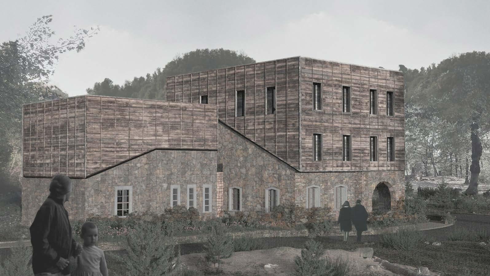
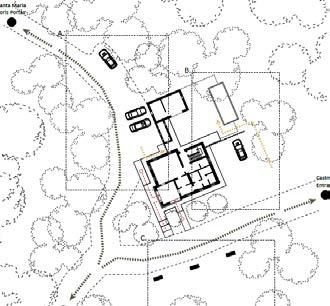
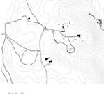
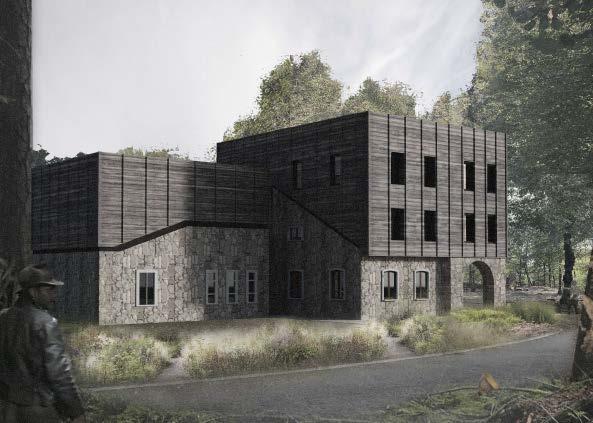
Castelseprio Archaeological Park
The Archaeological Park of Castelseprio town is situated in the province of Varese. It’s historical importance is such that the site is part of UNESCO world Heritage. The design involves renovating an existing building on site for administrative purposes.
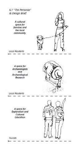
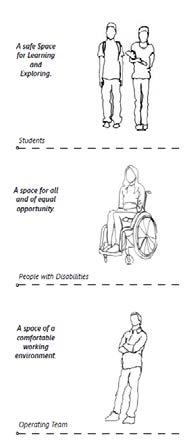
PERSONAS & DESIGN BRIEF
HISTORICAL BUILDINGS
LOCAL RESIDENTS
LOCAL RESIDENTS STUDENTS
PEOPLE WITH DISABALITIES
TOURISTS OPERATING TEAM
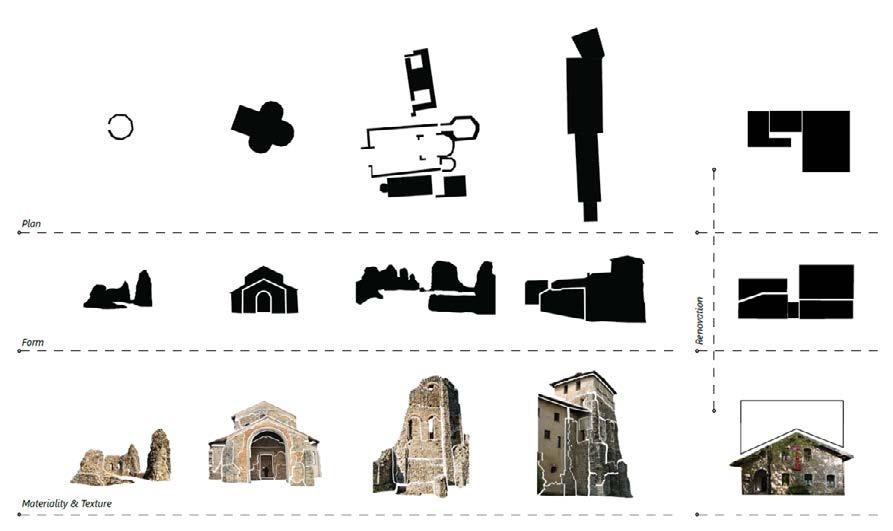
MATERIALITY & TEXTURE
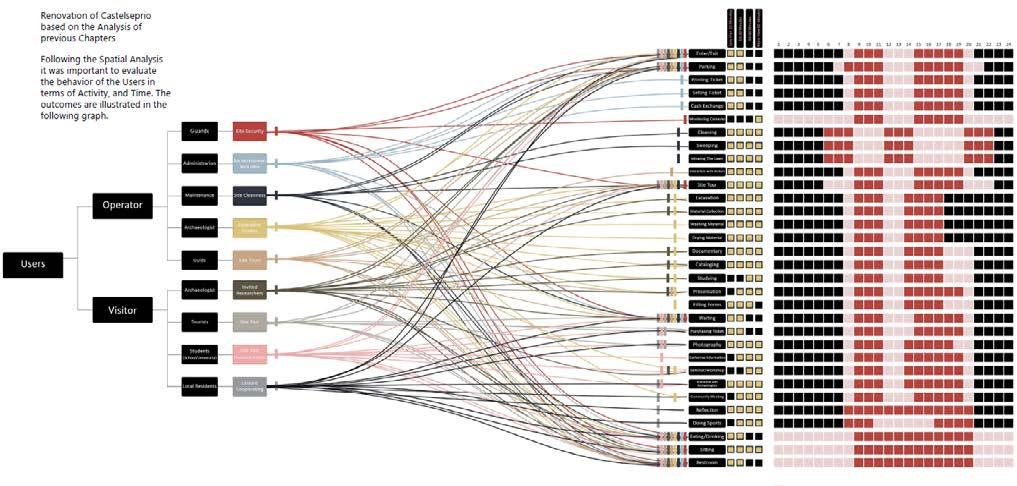
BEHAVIOR OF USERS WITH RESPECT TO ACTIVITIES AND TIME
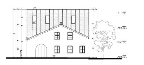
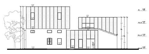
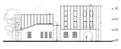
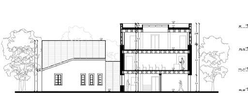
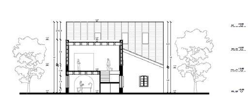
Existing Building
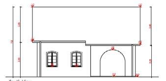
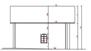
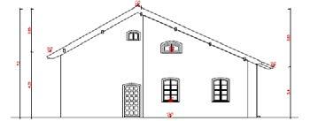
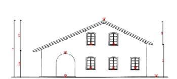
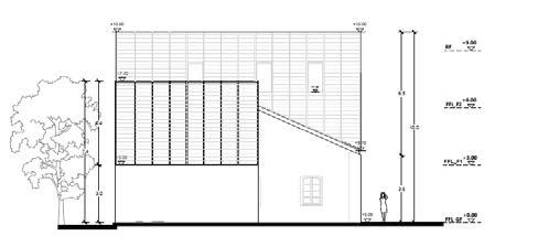
SOUTH ELEVATION
SCALE 1:100
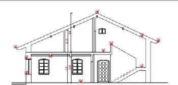
NORTH ELEVATION
SCALE 1:100
WEST ELEVATION
SCALE 1:100
EAST ELEVATION
SCALE 1:100
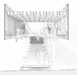
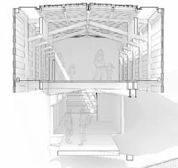
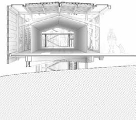
SECTION
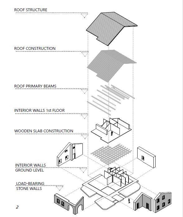
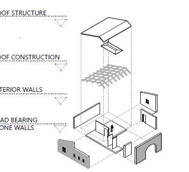
ROOF STRUCTURE
ROOF CONSTRUCTION
SCALE 1:100
ROOF PRIMARY BEAMS
INTERIOR WALLS 1ST FLOOR
WOODEN SLAB CONSTRUCTION
INTERIOR WALLS GROUND LEVEL
LOAD BEARING STONE WALL
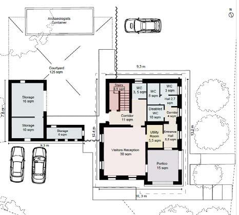
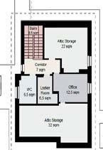
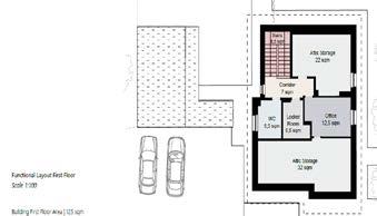
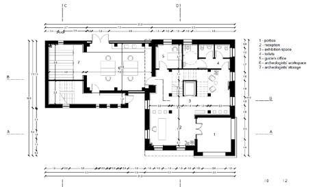
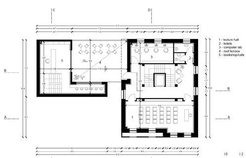
FUNCTIONAL LAYOUT
SCALE 1:100
ROOF STRUCTURE
ROOF CONSTRUCTION
INTERIOR WALLS
LOAD BEARING STONE WALL
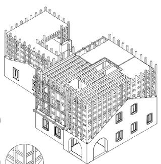
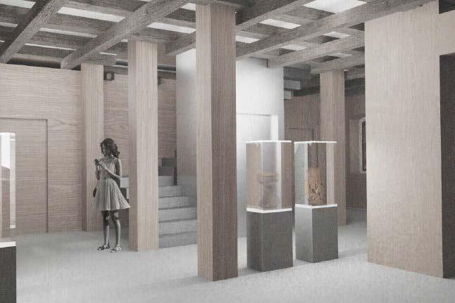
EXPLODED AXONOMETRIC OF MAIN BUILDING EXPLODED AXONOMETRIC OF STORAGE