ApplicationofElectricalEngineeringinMiningIndustry
2019Edition

This book is intended to provide a systematic approach to electrical engineering based on Australian Standards and NSW Work Health and Safety Legislations.
Australia is one of the largest producers and exporters of coal in the world, and coal mining plays an important role in Australian economy. Thanks to the application of electrical engineering, modern coal mines and coal processing plants in Australia enjoy high level of automation, efficiency and reliability to be competitive in production.
Meanwhile, electrical equipment and installations in mining industry are strictly regulated by legislations and it is critical that electrical risks can be managed by implementing effective controls, such as maintaining fit for purpose equipment, appointing competent personnel, and following safe work procedures.
Australian Standards and NSW Work Health and Safety Legislations are the key documentations for compliance, and electrical engineers are expected to develop sound practical skills and management skills to apply these documentations into practice. There is no such thing as good luck in mining industry, as good luck only comes from managing with persistent efforts.
In this book, balance is kept between breadth and depth of engineering theories. Case studies and electrical diagrams are provided to facilitate understanding. Much contents such as industry examples, safety requirements and decision makings may not be covered in university curriculum. Overall, this book aims to assist graduate engineers to bridge the gap between tertiary study and industrial practice, as well as assist developing career path to engineering managers.
Electrical Engineering in Practice
November 8, 2019 Newcastle, Australia
Part I Australian/New Zealand Standards 1
Chapter 1 “AS/NZS 3000: 2018 Electrical Installations (Wiring Rules) 2
Chapter 2 AS/NZS 3007: 2013 Electrical Equipment in Mines and Quarries – Surface Installations 15
Chapter 3 AS 2067: 2016 Substations and High Voltage Installations Exceeding 1 kV a.c. 30
Chapter 4 AS/NZS 2081: 2011 Electrical Protection Devices for Mines and Quarries 53
Chapter 5 AS/NZS 3010: 2017 Electrical Installations – Generating Sets 67
Chapter 6 AS/NZS 4871 Series Electrical Equipment for Mines and Quarries 79
Chapter 7 AS 61508 Series Functional Safety of E/E/PE Safety Related Systems 84
Chapter 8 AS 1674.2: 2007 Safety in Welding and Allied Processes (Part 2 – Electrical) 97
Chapter 9 AS/NZS 60079 Series Explosive Atmospheres 108
Chapter 10 AS/NZS 2290.1: 2014 Electrical Equipment for Coal Mines (Part 1 – For Hazardous Areas) 120
Chapter 11 AS/NZS 3800: 2012 Electrical Equipment for Explosive Atmospheres – Repair and Overhaul 123
Part II Work Health and Safety Legislations 128
Chapter 12 Legislation Compliance Requirements 129
Appendix Index 156
Topic 1.1 Methods of Electrical Protection 2
Topic 1.2 Protection by Automatic Disconnection of Supply 3
Topic 1.3 Overcurrent Protection Devices 5
There are two ways that allow an installation to be certified as compliant: AS 3000 Part 1 Compliance, or AS 3000 Part 2 Compliance.
As is described in AS 3000: 2018 Preface, Part 1 provides uniform essential elements that constitute the minimum regulatory requirements for a safe electrical installation; Part 2 provides installation practices that are deemed to comply with the essential safety requirements of Part 1.
Topic 1.1 Methods of Electrical Protection
Topic 1.4 Risk Associated with Arc Flash 10
Topic 1.5 Electrical Commissioning and Approval to Energise Form 12
Clause 1.5.1 Protection against dangers and damage The requirements of this Standard are intended to ensure the safety of persons, livestock, and property against dangers and damage that may arise in the reasonable use of electrical installations.
In electrical installations, the three major types of risk are listed below:
(1) Shock current: Shock current arising from direct / indirect contact.
(2) Excessive temperatures: Excessive temperatures likely to cause burns, fires and other injurious effects.
(3) Explosive atmospheres: Equipment installed in areas where explosive gases or dusts may be present shall provide protection against the ignition of such gases or dusts.
Clause 1.4.38 Direct contact Contact with a conductor or conductive part that is live in normal service.
Clause 1.4.39 Indirect contact Contact with a conductive part that is not normally live but has become live under fault conditions (because of insulation failure or some other cause).
Clause 1.5.4 Basic protection (protection against direct contact)
Methods of protection:
(1) Insulation material, (2) Barriers or enclosures, (3) Obstacles
(4) Placing out of reach
Methods of protection:
(1) Automatically disconnect the supply on the occurrence of a fault likely to cause a current flow through a body in contact with exposed conductive parts, where the value of that current is equal to or greater than the shock current, in accordance with Clause 1.5.5.3
(2) Prevent a fault current from passing through a body by the use of Class II equipment or equivalent insulation, in accordance with Clause 1.5.5.4
(3) Prevent a fault current from passing through a body by electrical separation of the system, in accordance with Clause 1.5.5.5. (Isolated supply)
NOTE: Clause 7.4 provides further guidance on electrical separation.
(4) Limit the fault current that can pass through a body to a value lower than the shock current.
NOTE: The most commonly used method of protection is automatic disconnection of supply.
AS 3000: 2018 Appendix B4 defines the principle of protection by automatic disconnection of supply
The principle of protection by automatic disconnection of supply is intended to prevent a person being subjected to a dangerous touch voltage for a time sufficient to cause organic damage, in the event of an insulation fault.
In order to meet this requirement, in the event of such a fault the circuit protective device must interrupt the resulting fault current sufficiently quickly to prevent the touch voltage persisting long enough to be dangerous.
This method of protection relies on the combination of two conditions: (a) The provision of a conducting path, designated the ‘earth fault-loop’, to provide for circulation of the fault current; and (b) The interruption of the fault current within a max time by an appropriate protective device. This maximum time depends on parameters, such as the highest touch voltage, the probability of a fault, and the probability of a person touching equipment during a fault.
AS/NZS 60479 defines two components that permit the establishment of a relationship between the prospective touch voltage and its duration, that does not usually result in harmful physiological effects on any person subjected to that touch voltage. These two components are: (a) The effect on the human body of electrical currents of various magnitudes and durations flowing through the body; and (b) the electrical impedance of the human body as a function of touch voltage.
Using the available information (as described in IEC/TR 61200-413), the required relationship between prospective touch voltage and disconnection time was derived shown in Figure 1.1.
Figure 1.1 Maximum Duration of Prospective 50Hz Touch Voltage (Copied from AS 3000: 2018 Appendix B)
These curves demonstrate that for normal conditions, A touch voltage of 50V may be sustained by a person indefinitely, and A touch voltage of 100V may not be sustained and must be disconnect.

As 230/400V is the most popular supply voltage, there is a requirement for maximum disconnection time for 230/400V supply voltage.
Clause 1.5.5.3 Protection by automatic disconnection of supply (d) Disconnection times
The maximum disconnection time for 230/400V supply voltage shall not exceed the following:
(i) 0.4 second for final sub-circuits that supply (A) socket-outlets having rated currents not exceeding 63 A; or (B) hand-held Class I equipment; or (C) portable equipment intended for manual movement during use.
(ii) 5 seconds for other circuits including submains and final sub-circuits supplying fixed or stationary equipment.
NOTE: Maximum disconnection times will vary for other voltages and installation conditions. Appendix B provides further guidance regarding disconnection times.
Reasons for 0.4-second disconnection time are explained in Clause B4.3.
A study was made of the influence of the variations in the different parameters on the value of the prospective touch voltage and the corresponding disconnection time.
The prospective touch voltage ���� for a circuit is defined by: ���� = �������� 1+��
Where ���� is the nominal r.m.s. voltage to earth; �� is the proportion of the supply voltage available at the reference point during operation of protective device; �� is the ratio of the cross-sectional area of the phase conductor compared to the cross-sectional area of the protective earthing conductor in the circuit.
Depending on the circuit considered, the factor �� may vary from 0.6 (e.g. a circuit very far from the source) and 1.0 (e.g a circuit supplied directly from the source). In the event of fault, in average approximately 20% of voltage drop is in upstream, and 80% voltage drop in final sub-circuit. It is assumed that phase conductor and the protective earth conductor are of the same size, i.e. half of voltage drop in phase conductor, and half in earth conductor.
As a result, using a mean value of 0.8 for the factor �� and a ratio �� of 1, the prospective touch voltage ���� for a circuit is given by: ���� = �������� 1+�� = 0.8×230×1 1+1 =92��
It can be checked in Figure 1.2 that, when 92V is applied to human body, the maximum duration is above 0.4 second and under 0.5 second for human touch. Thus, 0.4 sec is selected to be the automatic disconnection time.
Figure 1.2 Maximum Duration of Prospective 50Hz Touch Voltage of 92 volts (Copied from AS 3000: 2018 Appendix B)

Reasons for 5-second disconnection time are also explained in Clause B4.3.
Clause B4.3 Disconnection times
(1) Faults in such circuits are less likely;
(2) There is less likehood of persons being in contact with equipment supplied by such circuits during a fault;
(3) Equipment supplied by these circuits is usually not gripped and therefore be released easily if a fault occurs;
(4) Touch voltages are not expected to exceed the values in accordance with Figure 1.1 for the time/touch-voltage relationship.
The tripping characteristics of a circuit breaker can be represented by time-current curve. The curve shows the amount of time required for a circuit breaker to trip at a given overcurrent level.
The upper-left portion of the curve displays the thermal response of the circuit breaker. On low-fault current levels, thermal tripping occurs when a bimetal conductor in the breaker responds to heat associated with the overcurrent. The bimetal conductor deflects, de-latching the mechanism and mechanically causing the circuit breaker to trip and open the circuit. The larger the overload, the faster the breaker will operate to clear the circuit.
The lower right portion of the curve displays the magnetic tripping response of the circuit breaker. This takes place when overcurrents of sufficient magnitude operate an integral magnetic armature which de-latches the mechanism. Magnetic tripping occurs with no intentional time delay.
Electronic trip circuit breakers are characterized by their adjustability. By adjusting the settings of the available trip unit functions, different tripping characteristics can be achieved. Figure 1.3 shows various discrete segments of the trip curve that can be adjusted on a circuit breaker.
Figure 1.3 Typical time-current curve of circuit breaker and fuse
Long-time delay typically protects equipment in the event of overload; Short-time pickup and short-time delay are typically for motor starting, or transformer inrush conditions; Instantaneous pickup is to protect equipment during phase-to-earth fault or phaseto-phase fault.

Useful Resources: Schneider Electric Data Bulletin No. 0600DB0105 - Characteristic Trip Curves and Coordination
https://www.se.com/us/en/download/document/0600DB0105/
AS 3000 Clause B3.1 defines protection against overcurrent:
The term ‘overcurrent’ includes both overload current and short-circuit current.
The dangner to the system from overload currents is that the temperature of conductors and their insulation will rise to levels at which the effectiveness of the insulation and its expected service life will be reduced.
Short-circuit currents may be up to several thousand times normal current and will cause overheating and mechanical stresses of conductors and associated connections.
Clause 2.5.1 requires active conductors to be protected by one or more protective devices in the event of overload or short-circuit.
The protection of cable by circuit breakers and fuse is shown in Figure 1.4. The conductor is deemed to be protected if its damage curve is to the right of the time/current curve of the protective device.

According to AS 3000 Clause 2.5.3.1, the operating characteristics of a device protecting a conductor against overload shall satisfy the following two conditions:
For circuit breakers: ���� ≤ ���� ≤���� ��2 ≤ 1.45×����
For fuses: ���� ≤ ���� ≤0.9���� ��2 ≤ 1.6×���� Where ����
The current for which the circuit is designed (e.g. maximum demand) ���� The nominal current of the protective device ���� The continuous current-carrying capacity of the conductor ��2 The current ensuring effective operation of the protective device and may be taken as equal to either: (a) the operating current in conventional time for circuit breakers (1.45����); or (b) the fusing current in conventional time for fuses (1.6���� for fuses in accordance with the AS 60269 series).
Note:
To prevent cable damage, circuit breaker must trip within 1 hour when subject to 145% overload setting, while High Rupturing Capacity (HRC) fuses must trip within 1 hour when subject to 160% of overload settings. Thus, 1.6 × HRC fuse size = 1.45 × cable rating, and HRC fuse size = 0.9 × cable rating.
Figure 1.4 Protection of cable by circuit breakers and fuse
According to AS 3000 lause 2.5.3.1, protection devices shall be provided to limit, as far as practicable, the harmful effects of a switchboard internal arcing fault (short-circuit current) by automatic disconnection. The arcing fault current between phases or between phase and earth, is deemed to be in the range of 30% to 60% of the prospective short-circuit current.
Protection shall be initiated, when less than 30% of the three-phase prospective fault level is picked up.
The general damage limit is given by: �� = ����×���� ���� 15 Where �� Clearing time in seconds ���� 30% of the prospective fault current ���� Current rating of the switchboard ���� 250 constant, based on acceptable volume damage. For example, for an 800A-rated main switchboard with a prospective fault current of 16.67kA, ���� =16.67×30%=5���� �� = ����×���� ���� 15 = 250×800 (5000)15 =0.566������
The protective device settings must be set to clear an arcing fault of 5kA in less than 0.566 seconds.
Miniature circuit breakers (MCBs) are electromechanical devices which protect an electric circuit from an overcurrent. Mean tripping currents for Type B, C and D miniature circuit breakers are defined in Clause B4.5, and current curves are shown in Figure 1.5. Note that the curve type is “C curve”.
Figure 1.5 Mean tripping currents of Type B, C and D circuit breakers
Type B: 4 × rated current; Type C: 7.5 × rated current; Type D: 12.5 × rated current.
Type B MCB trips between 3 and 5 times full load current. They are mainly used in residential or light commercial applications where connected loads are primarily lighting fixtures, domestic appliances with mainly resistive elements. The surge current levels in such cases are relatively low.
Type C MCB trips between 5 and 10 times full load current. This is used in commercial or industrial type of applications where there could be chances of higher values of short circuit currents in the circuit. The connected loads are mainly inductive in nature (e.g. induction motors) or fluorescent lighting.
Type D MCB trips between 10 and 20 times full load current. These MCBs are use in specialty industrial/commercial uses where current inrush can be very high. Examples include transformers or large winding motors etc.

AS 3000 Clause 2.5.7.2 Coordination of Protective Device describes circuit breaker curves and fuse curves with discrimination requirements.
(iii) For ratings of ��2 < 250A, Discrimination should be provided between overload curves, and is recommended up to the instantaneous setting ���� or short-time pickup ������ of ��1, but need not apply above the arcing fault current ��������.
Discrimination is deemed to be achieved if ��1 ≥ 1.5 ×��2, e.g. ��1 MCB marked C63 with ��2 MCB marked C40 (time-current curves are both C curves).


As is shown in Figure 1.6, discrimination is achieved when Protection Device 1 remains intact while Protection Device 2 clears a fault on the load side. Thus supply is maintained to Protection Device 3 and the remainder of the electrical installation.
As shown in Figure 1.7, two circuit breakers, connected such that ��2 is the downstream device and ��1 the upstream device, shall be selected as follows:
(i) For ratings of ��2 ≥ 800A, Discrimination shall be provided between overload curves and instantaneous settings, but need not apply above the arcing fault current ��������.
(ii) For ratings of ��2 ≥ 250A up to < 800A, Discrimination shall be provided between overload curves, and is recommended up to the instantaneous setting ���� or short-time pickup ������ of ��1, but need not apply above the arcing fault current ��������
Discrimination is deemed to be achieved if the overload setting of ��1 ≥ 1.5 ×��2, e.g. ��1 1000A with ��2 630A.
Figure 1.7 Circuit breaker curves with discrimination requirements (Figure derived from AS 3000: 2018 Section 2)
Note that the following terms are used: �������� Prospective short-circuit current; �������� Deemed maximum acing fault current (30% ~ 60% ��������); ���� Instantaneous setting; ������ Short delay setting; 0.01s The limit of the fuse time-current.
As is shown in Figure 1.8, two fuses connected such that ��2 is the downstream device and ��1 is the upstream device shall be selected such that the characteristics of the device provide discrimination (selectivity) on overload.
Discrimination between HRC fuses is deemed to be achieved –
(i) For overload when ��1 ≥ 1.6 ×��2, e.g. 16A with 10A
(ii) For short-circuit when ��1 ≥ 2 ×��2, e.g. 20A with 10A
Note: Overload curves are those for times > 0.01s. Short circuit data is based on the total ��2�� of ��2 ≤ pre-arcing ��2�� of ��1.
As is shown in Figure 1.9, a fuse and a circuit breaker connected such that ��2 is the downstream device and ��1 is the upstream device shall be selected such that the characteristics of the devices provide discrimination between the overload curve and the instantaneous setting or short delay setting (������) of ��2 and the timecurrent curve of ��1.


Figure 1.8 Fuse curves with discrimination requirements (Figure derived from AS 3000: 2018 Section 2)
Figure 1.9 Fuse and circuit breaker curves with discrimination requirements (Figure derived from AS 3000: 2018 Section 2)
In 2019 Energy Safe Victoria provided a guideline on arc flash hazard management. It explains the causes of arc flash as below:
Arc flash incidents occur when low impedance electrical connections are inadvertently made across phases, phase to neutral or from phase to earth. These connections can occur by accidental contact across terminals from tools or equipment, a breakdown in insulation or from a build-up of contaminates such as carbon or dust. Most arc flash incidents occur when high risk activities, such as operating or racking of circuit breakers are being carried out, however arc flash incidents can occur at any time.
This guideline provides controls for arc flash hazards shown in Table 1.1.
Table 1.1 Hierarchy of controls for arc flash hazards (derived from guideline)
Eliminate Eliminate the exposure of personnel to arc flash hazards by only interacting with de-energised and isolated equipment.
Substitute
Substitute manual operating systems for automated operating systems.
Isolate personnel from the hazard by installing physical separation from energised equipment or conductors.
Engineering controls
Fixed circuit breakers over rackable breakers for new installation/upgrades
Insulated bus bars
Installation design consideration for isolation/maintenance tasks Replacement of fuses which provide faster clearance times
Label all switch rooms, plant and relevant locations to identify incident energy levels and the appropriate actions / precautions that need to be taken
Demarcation of arc boundaries
Make arc flash registers and diagrams available for workers
Establish effective policy and procedure that reduces exposure, including training and inductions
Implement of an incident energy and PPE category system as detailed in IEEE 1584 and ENA NENS 09 – 2014 or equivalent published standards.
PPE is the least effective control and should not be relied upon unless combined with other controls. PPE does not prevent injury but may reduce severity.
To select the appropriate PPE for an electrical arc flash hazard environment, the following steps need to be undertaken.
Switchboards can be constructed to contain the energy associated with an arc event.
Limit incident energy with reduced fault current and/or reduced fault clearance times by adjusting circuit breaker settings.
(1) Understand the hazard.
(2) Identify assets or asset groups with arc flash/fault hazard potential.
(3) Quantify the hazard – calculate the incident energy in each relevant location.
(4) Assess the risk – using your organisation risk management framework.
System modifications:
Arc flash detection and suppression system
Remote racking devices
Upgrade switchboard form type
Upgrade/modify boards to allow for racking with the door closed
(5) Reduce the risk, so far as is reasonably practicable, using the hierarchy of controls.
(6) Select the appropriate PPE if a residual risk of injury is present
Arc fault category, incident energy and PPE requirements are shown in Table 1.2. PPE manufacturer can be consulted for the correct arc flash category.
Table 1.2 Arc flash category and PPE requirement chart
Arc flash Category Incident Energy PPE requirements
Long-sleeve shirt
0 0-4 cal/cm2
Long pants Hard hat
Safety glasses
Arc-rated long-sleeve shirt
Arc-rated pants or coverall
Arc-rated face shield with hard hat
Your Electrical Engineering Control Plan shall take the following into account to manage the risks to health and safety from electricity at your coal mine.
WHS (Mines) Regulation 2014 Schedule 2, Clause (3) (b) Identifies: The rating and design of plant for the prospective electrical fault level, electrical load, operating frequency, operating voltages and arc fault control.
As a newly appointed electrical engineering manager you become aware that the aging electrical infrastructure within your mine has not been assessed or appropriate controls implemented to deal with arc flash control.
a) Formulate an action plan to manage this risk at the operation in relation to arc flash control.
1 4-8 cal/cm2
Safety glasses
Leather & voltage rated gloves
Leather work boots
Arc-rated long-sleeve shirt
Arc-rated pants or coverall
Arc flash suit hood with hard hat
Action plan to manage arc flash risk is listed in Table 1.3.
Table 1.3 Arc fault control action plan
2 8-25 cal/cm2
Safety glasses
Leather & voltage rated gloves
Leather work boots
Arc-rated long-sleeve jacket
Arc-rated pants
3 25-40 cal/cm2
Arc-rated face hood with hard hat
Leather & voltage rated gloves
Leather work boots
Arc-rated long-sleeve jacket
Arc-rated pants
4 >40 cal/cm2
Arc-rated face hood with hard hat
Leather & voltage rated gloves
Leather work boots
Issue Action By who Due date Switching procedures expose electricians to risk Procedures to be updated for remote switching Electrical Engineer 2 weeks
Electricians not aware of correct switching procedure Training for correct switching procedure Trainer Assessor 2 weeks
Load flow study and arc flash study out of date
Aging switchgears and equipment
Remote switching not available in some areas
Guideline on arc flash hazard management from Energy Safe Victoria: https://esv.vic.gov.au/wpcontent/uploads/2019/10/Arc_flash_hazard_guideline_Oct19.pdf
Poor maintenance of switchgears
Complete load flow study and arc flash study, assign arc flash category, review fault level and protection settings.
Electrical Engineer 4 weeks
Complete an audit for switchgears and review their conditions Electrical Engineer 4 weeks
Implement remote switching such as remote control panel, pendant and/or SCADA Electrical Engineer 6 weeks
Update inspection sheets Electrical Engineer 2 weeks Keep regular maintenance and testing of switching gears Electrical Supervisor 2 weeks
PPE not suitable Ensure PPE with suitable arc flash ratings Electrical Supervisor 4 weeks
b) You need to draft a memo to your Mine Manager in relation to these risks and the requirement for capital expenditure for arc flash control at your mine. What would be your key elements in the memo?
Problems: Aging equipment arc fault control not meeting legislation requirement or Australian Standards.
Risk assessment needs to be conducted for existing arc flash ratings. Risks to be controlled associated with arc-fault: electric shock, electric burn, ignition of gas/dust, fire.
Short term solutions:
(1) Complete a fault level and arc flash study for all electrical equipment on site, evaluate fault level, arc flash level, and the required protection settings. Label arc flash category, provide PPE with suitable arc flash ratings.
(2) Develop procedures for remote switching (pendant, remote panel, SCADA)
(3) Training for electricians for correct switching procedure.
Long term solutions:
(1) Complete an audit for switchgears and review their conditions. Investigate reducing arc fault levels by faster switchgear, arc-resistant switchgears or HRC fuses.
(2) Implement remote switching devices for switchgears.
(3) Routine maintenance of switch gears, check for dust build-up, overheating of insulation etc.
Outcome: the likelihood and consequence of arc flash are reduced, and significantly improved safety for personnel.
Note: Arc flash incident energy is proportional to fault clearance time. As a result, proper selection of short-circuit protective devices that quickly clear arcing faults is a powerful mitigation strategy.
1.4.3
You are the electrical engineering manager at a mine and you have received a Safety Alert describing an incident where an electrician received an electric shock and an electrical burn to his hand whilst carrying out routine maintenance in a withdrawable 415V 37kW pump cell in a motor control centre (MCC). The MCC has a design fault rating of 65kA and the modelled maximum fault level of the installation is 25kA.
a) List three design features you may find on the 37kW pump MCC cell to prevent contact with live conductors.
Door interlock, enclosure, IP2X form rating, insulation
b) List the design features you may find on the 37kW pump cell to eliminate or mitigate arcing faults.
Arc resistant enclosure, segregated compartment, arc blast duct, protection device, remote switching
c) List three administrative controls you would expect to see in place to manage the risks associated with this type of incident.
Competency of workers, correct work procedure, remote switching, arc flash category signage, and provision of suitable PPE
d) The following warning is provided in the manufacturer’s Installation manual:
ATTENTION: De-energize, lock out, and tag out all sources of power to the MCC when you install or remove MCC units. If MCC units are installed or removed with power applied to the main power bus, follow established electrical safety work practices.
List two key conditions you would include in a procedure for the withdrawal of an MCC unit with the main power bus energised.
(1) Ensure offload;
(2) Confirm arc fault category, and use suitable PPE that suitable for that category; However, if arc fault category is labelled “Dangerous” (above Category 4), then the bus shall be de-energised.
Note: It is common that the 415V incomer circuit breaker (e.g. Terasaki Tempower 2 AR440S) has “Dangerous” arc flash level. If remote racking is unavailable and have to manually racking 415V incomer circuit breaker, the upstream transformer shall be de-energised by opening upstream high voltage circuit breaker.
The requirements of commissioning are listed in AS 3000 Section 8 Verification.
Typical site electrical commissioning plan should include:
(1) Require a Certificate of Compliance
(2) Verify circuits as per drawings
(3) Test all safety functions
(4) Test as per original equipment manufacturer (OEM)'s recommendations
(5) Guarding as necessary during commissioning
(6) Site notification about energization
Visual inspection and testing (includes functional tests and measuring) are two major activities that you must undertake to ensure a compliant installation. Details of visual inspection are listed in clause 8.2; Details of testing are listed in clause 8.3.
Mandatory tests are listed in Clause 8.3.3:
The following tests shall be carried out on low voltage installations:
(a) Continuity of the earthing system (main earthing conductor, protective earthing conductors and bonding conductors), in accordance with Clause 8.3.5.
(b) Insulation resistance, in accordance with Clause 8.3.6.
(c) Polarity, in accordance with Clause 8.3.7.
(d) Correct circuit connections, in accordance with Clause 8.3.8.
(e) Verification of impedance required for automatic disconnection of supply (earth fault-loop impedance), in accordance with Clause 8.3.9.
(f) Operation of RCDs, in accordance with Clause 8.3.10.
Note: High voltage installations may require additional test in AS 2067.
Note that for testing, multimeter of Category III and Category IV shall be used on a mine site.
Handbook HB 187 – 2006 Guide to Selecting a Safe Multimeter defines the categories for multimeters, shown in Table 1.4.
Table 1.4 Multimeter categories (copied from HB 187 – 2006)
CAT I – very low energy circuits e.g. Vehicles, battery-powered circuit (not connected to 240V)
CAT II – low energy circuits e.g. Domestic use (up to 5 kA fault currents)
CAT III – medium energy circuits e.g. Industrial + commercial use (up to 25 kA fault currents)
CAT IV– high energy circuits e.g. Industrial + commercial use (above 25 kA fault currents)
To test the continuity of earthing system for a single-phase pump installation supplied 100 metres from the motor control centre (MCC), the below steps can be followed: (1) Complete isolation at MCC. (2) At the motor, install a bridge between phase conductor and earth conductor. Measure resistance: ����ℎ������ +����������ℎ =�� (3) At the motor, remove the bridge between phase conductor and earth conductor. Install a bridge between phase conductor and neutral conductor. Measure resistance: ����ℎ������ +���������������� =�� (4) Calculate earth conductor resistance: ����ℎ������ =���������������� = �� 2 ����������ℎ =�� �� 2
Approval to Energise Form shall be completed and approved by electrical engineering manager before energizing above extra-low voltage for electrical equipment and electrical installations.
This form should include: (1) Verification of basic information Person responsible for work Contract company name Equipment number and name As-built drawings Equipment description (2) Energisation checklist Confirm construction/energisation commissioning have been completed Completed commissioning test and inspections sheets are provided Confirm outstanding or defect Items detailed in construction punch list Confirm controls in place for punch list items to allow energisation to continue
Drawings marked-up to ‘As built’ status Confirm Protection Settings correct and recorded Introduction to site paperwork attached Any defects and remedial actions shall be noted in comments.
One the form completed, it shall be signed off by electrical tradesperson, electrical supervisor and electrical engineering manager.
Figure 1.10 Earth continuity test technique for motors

Contents
Topic 2.1 TN, TT and IT Earthing Systems 15
Topic 2.2 Specific Power Supplies 18
Topic 2.3 Design and Protection Requirements 21
Topic 2.4 Overhead Power Lines 22
There are mainly three types of earthing systems: TN, TT and IT earthing system. As is described in AS 3007 Appendix A, the codes used in the description of the systems have the following meaning:
(a)
The relationship of the earthable point of the power system to earth, as follows: T = direct electrical connection (minimum practical impedance) to earth. I = no connection (all live parts isolated from earth) or connected to earth through an impedance (resistor or reactor) or equivalent circuit.
The relationship of the exposed conductive parts of the electrical installation to earth, as follows:
Topic 2.5 Reclaim Tunnel 24
Topic 2.6 Cable Management 26
T = direct electrical connection (minimum practical impedance) to earth, independently of any connection to the earthable point of the power system. N = direct electrical connection (minimum practical impedance) to the earthable point of the power system.
Details of earthing systems are discussed from section 2.1.1 to 2.1.3.
Power systems having the earthable point directly connected to earth, the exposed conductive parts of the installation being connected by protective conductors to the earthable point of the power system.
Figure 2.1 TN earthing system with separate neutral and protective conductors
Figure 2.3 TN earthing system with neutral and protective functions combined in a single conductor throughout the system
In TN systems, the earthable point (in three-phase systems commonly the neutral point of the power system) and exposed conductive parts are interconnected by a protective conductor. In the case of a short-circuit from a phase conductor to the protective conductor or exposed conductive parts, the resultant fault current initiates, through a protective device, disconnection of the supply to the defective equipment.


To ensure that, in case of a fault (to exposed conductive parts or to earth), the potential of the protective conductor and of the exposed conductive parts connected to it differs as little as possible from the earth potential, the protective conductor should be connected to a number of earthing points distributed so as to obtain the lowest practical earthing impedance.
Figure 2.2 TN earthing system with neutral and protective functions combined in a single conductor in a part of the system
Clause A2 (b) TT system
Power systems having the earthable point directly connected to earth, the exposed conductive parts of the installation being connected to earth electrodes which are electrically independent of the earth electrodes of the power system.
Clause A2 (c) IT system
Power systems having the earthable point not connected to earth, or connected to earth through deliberately inserted impedance (resistor or reactor), the exposed conductive parts of the installation being connected to earth electrodes which may be the same as those used for the earthing resistor or reactor.
Figure 2.5 Power system IT with independent earth electrodes
Clause A4.1 General
Figure 2.4 TT earthing system
In TT systems, the earthable point (neutral point) is directly connected to an earth electrode with no impedance (other than the impedance of the protective conductor) being inserted between the earthable point and the earth electrode.


The exposed conductive parts are connected, either individually, in groups, or as a whole, to one or several earth electrodes independent of the earth electrode of the earthable point.
Figure 2.6 Power system IT with common earth electrode

In IT systems, the earthable point of the power system is either isolated from earth or earthed through an impedance, and the exposed conductive parts are connected to one or several earth electrodes either individually, in groups or as a whole.
Benefits of IT earthing system is also in Clause A5.1: Impedance earthed IT systems may(a) significantly reduce the earth potential rise with a consequent reduction in touch and step voltages and transfer potentials; (b) in conjunction with sensitive earth leakage protection, significantly reduce the damage sustained by electrical equipment under earth fault conditions; (c) reduce the likelihood of an earth fault propagating into a multi-phase arc flash/blast event. This reduction is because the destruction and melting of copper is generally insignificant with the low earth fault current and therefore propagation into a multiphase fault is highly unlikely; and (d) significantly reduce the arc flash and incident energy under earth fault conditions (by a number of orders of magnitude) compared to solidly earthed systems.

AS 3007 provides requirement for inspecting earth fault current limiting devices:
Clause 3.5 Earth fault protection on impedance earthed IT systems
Earth fault current limiting devices should be inspected annually
Following the activation of a backup earth fault protection scheme, the earth fault current limiting device shall be inspected unless an NER integrity monitor is fitted.
Relocatable buildings are usually pre-wired based on TN earth system and arrive on site in a ready to connect state. When they are connected to mine site power supplies, risks shall be identified and controlled.
Clause 8.5.1 says, where relocatable buildings designed for use on a TN system are to be connected to an IT system, the neutral for the relocatable building shall not be derived from the neutral point of the IT system.
Risks of above are listed in Clause A5.6 Neutral conductor in IT systems.
Loads should not be supplied from the neutral of an IT system. If a single-phase load has to be connected to these systems then it has to be done via an isolation transformer. This ensures that an earth fault on the neutral will not bypass the NER.
The issue is that the touch potential of the neutral is no longer the same as the earth system. Under certain fault conditions, the following issues arise:
(a) The prospective touch voltage may increase.
(b) An earth fault on the neutral will bypass NER, resulting in an unrestricted earth fault.
(c) The backup earth fault protection may not see the fault as it is bypassed.
(d) The earth fault detection relay may not be suitable for use in a system with an unlimited earth fault and therefore may not register the earth fault, even if not bypassed.
Figure 2.8 Designated earth fault loop in IT system, and earth fault is limited by NER


As is described in Clause 8.5.1, to overcome the above issues, an isolation transformer shall be installed between the IT supply and the relocatable building. The isolation transformer options are as follows:
(a) 415/240V 3 phase IT connected isolation transformer (delta-star connection). This increases the protection against electric shock, as the phase-to-earth voltage is now 139V.
If this option is selected, the special requirements identified in Clause 8.5.2 shall be implemented with regard to the switches and outlets installed in the relocatable building (double-pole switches are required).
Figure 2.9 Earth fault-loop in IT system with neutral to earth fault, and NER is bypassed during phase to earth fault (Neutral conductor shall NOT exist in IT system)

Figure 2.10 Three phases IT connected isolation transformer, and power outlet requires double-pole switch
Three phases IT connected isolation transformer secondary side: phase-phase voltage: 240�� phase-earth voltage: 240/√3=139��

(b) 415/240V 2 phases IT (via centre tap on the 240V winding) connected isolation transformer. This increases the protection against electric shock, as the phase-to-earth voltage is now 120V.
If this option is selected, the special requirements identified in Clause 8.5.2 shall be implemented with regard to the switches and outlets installed in the relocatable building (double-pole switches are required).
(c) 415/240V 2 phases TN (one phase of the 240V winding is earthed) connected isolation transformer (double-pole switches are NOT required).
Figure 2.11 Two phases IT (via centre tap on the 240V winding) connected isolation transformer, and power outlet requires double-pole switch
Two phases IT (via centre tap on the 240V winding) connected isolation transformer secondary side: phase-phase voltage: 240�� phase-earth voltage: 120��
Figure 2.12 Two phases TN (one phase of the 240V winding is earthed) connected isolation transformer, and power outlet does not have to use double-pole switch


Two phases TN (one phase of the 240V winding is earthed) connected isolation transformer secondary side: phase-phase voltage: 240�� phase-earth voltage: 240��
Clause 8.5.2 specifies the requirement for Isolation Switches: If the 240 V supply is an IT system all conductors shall be considered as active and shall be switched in accordance with AS 3000. This includes isolation switches for air conditioners, hot water services, lighting services, etc., i.e. double-pole switches are required.
1. What is a ‘closed operating area’ and list two examples.
Clause 1.3.2 Closed electrical operating area
An area dedicated for the operation of electrical installations and equipment to which access is intended to be restricted to skilled or instructed persons or to lay personnel under the direct supervision of skilled or instructed persons.
(1) Examples of such locations include substations, enclosed switchgear and distribution installations, transformer enclosures, enclosed switchgear bays or cubicles, distribution installations in sheet metal housings or in other closed installations.
(2) Typically access to closed areas is only by the use of a key or tool to open a door or remove a protective barrier, and where that access is clearly marked by appropriate warning signs.
4. What consideration shall be given to fault levels of electrical circuit?
Clause 3.1.2 System fault levels
Consideration shall be given to the fault levels of electrical circuits to ensure the electrical equipment and cabling are rated for the system fault level.
(1) Any protection study undertaken should take into consideration the effects of minimum and maximum possible fault levels.
(2) Overcurrent protection arrangements should take into consideration the reduction of risk from arc flash and blast by ensuring short-circuit faults are detected at the minimum practicable current and the fault cleared in the quickest possible time.
(3) Use impedance earthed IT systems and the potential advantages in reducing arc flash risks.
(4) The use of arc-detection devices or other specialist arc flash protection devices may reduce the impact of an arc flash event.
2. What is the specific requirement for removal of power in a closed electrical operating area?
Clause 2.5 Removal of power in a closed electrical operating area
Emergency shutdown facilities shall be provided to enable power to be removed from a closed electrical operating area without the need to enter that operating area, e.g. an emergency stop located external or remote to a switch room.
3. What design provisions are to be included for the prevention of arc flash/blast protection injury?
Clause 2.8.5 Arc flash/blast protection
Positioning of operating handles
Explosion vents
Integrity and guarding of windows
Considerations should be given to the used of remote switching.
For remote operation of equipment or plant, such as a circuit breaker operated by a pendant, the safety of the control shall be taken in to account and shall be rated in accordance with a functional safety analysis.
5. What is the general rule for protection of electrical equipment and live conductors when it comes to protection against overloads and faults?
Clause 3.2
Electrical equipment and live conductors shall be protected by one or more devices for automatic interruption of the supply in the event of overcurrent due to overload and short-circuits except as identified in Clause 3.3. Protection against overload and against short-circuits shall be coordinated in accordance with Clause 3.4.
6. Name the places that overloads should NOT be installed.
Clause 3.3 Overload protective devices should not be installed in conductors supplying electrical equipment where the unexpected opening of the circuit could cause a danger greater than not opening the circuit. Such cases may include but not be limited to the following:
(a) Excitation circuits for d.c. and a.c. (synchronous) motors.
(b) Supply circuits of lifting magnets.
(c) Current transformer secondary circuits.
(d) Fire service pumps and certain drainage pump installations.
(e) Elevators (lifts).
(f) Hoists.
(g) Special hydraulic pumps.
(h) Excavator main drives.
(i) Certain conveyors.
(j) Certain braking circuits.
(k) Emergency lighting and signalling.
(l) Certain drainage pump installations.
7. What is the requirement for miniature circuit breakers inside low voltage distribution boards?
Clause 2.10.2
For low voltage distribution boards containing miniature circuit-breakers, where two or more circuit-breakers are mounted in the same row, the operating mechanism of each shall cause the circuit to open when the operating means are orientated in one general direction.
Where multiple horizontal rows of circuit-breakers are contained within a switchboard, each row of circuit-breakers shall operate in the one general direction, and shall have additional labelling to clearly indicate the ON/OFF position.
2.4.1
Over Head Lines (OHL) are installed in open-cut mines to supply transportable substations. OHL Corridors and Work near OHLs require certain criteria set in relation to the minimum distances so that direct contact or flashover is prevented under normal operating or foreseeable abnormal circumstances.
General requirements for OHLs is listed in Clause 7.1:
(1) OHLs at mines shall be designed to function properly and minimize the risk of direct contact.
(2) OHLs shall be designed and installed so as to ensure adequate mechanical strength, clearances and current carrying capacity.
(3) Clearances may need to be increased above the published values where operations associated with mining and transport take place near the OHLs.
(4) Earthing conductors shall be installed above the OHLs along their length to protect the OHLs from lightning strikes.
(5) Signs should be installed at appropriate places to warn the presence of OHLs. The signs shall state the voltage and the maximum height of any mobile plant that can travel under OHLs.
8. What are the specific requirements for isolating equipment and machinery for electrical isolation?
Clause 4.2
Isolating facilities by means of which all power to the machinery can be isolated for the purpose of carrying out electrical work shall be provided. The isolating facilities shall be capable of being locked in the isolated position. The isolating facilities shall be either in a separate compartment or remote from the machinery to isolate the supply cable
Before constructing OHLs, environmental team and mine planning team shall be consulted, and the below issues should be considered:
(1) Assess the impact to environment and heritage, do not access if mining approval is not issued for that area;
(2) Assess strata stability
(3) Consider interaction with mining activities, mobile plant, drill and blast;
(4) Ground Disturbance Permit to be completed and approved.
Obtain service plan from surveyors to identify the services, and propose routes; Surveyors to update service plan before backfilling.
9 What needs to be maintained over the full life cycle of electrical equipment as far as information requirements?
Clause 2.13.8 Information requirements Safety file (or verification dossier)
Minimum clearance shall be kept between overhead lines and mobile plants or structures. Minimum clearance is provided in Table 2.1.
Table 2.1 Minimum clearance for the movement of vehicles and machinery under and in the vicinity of OHLs (Copied from AS3007:2013 Table 7.1)
Nominal voltages (phase to phase) kV, r.m.s
Minimum clearance (mm)
≤1.1 1000
>1.1 ≤33 2300
>33 ≤66 2500 >66 ≤110 3000 >110 ≤220 4000
Notes: The minimum clearances specified take into account the fact that the system voltage may vary by up to 10% from the nominal voltage; Allowance should be made for the possible sag and swing of the OHL.
When working near live OHLs, “No-Go Zones” of OHLs are shown in Figure 2.14 and Figure 2.15.
Figure 2.15 Overhead power lines on poles / on towers (nominal voltage > 33kV) (Copyright AS 3007:2013)
Figure 2.14 Overhead power lines on poles / on towers (nominal maximum voltage 33kV) (Copyright AS 3007:2013)


You have recently commenced work at a mine as the electrical engineering manager and have identified that there are a large number of different power lines that cross the lease. While driving around the site, you note two large exploration drills working in what appears to be close proximity to a 33kV overhead lines.
a) How would you manage this scenario in the first instance?
Stop working party and conduct safety observation (check competency of workers, check JSA, check if work procedure is followed); Check clearance and assess if safety observer is required; Notify supervisor if procedure is not followed. Note that when workers say they see the OHLs does not guarantee that they follow the correct procedure.
b) What systems would you expect to be in place at the site to manage work near overhead lines?
Electrical Engineering Control Plan (n) requires procedure to work near OHLs; Risk assessment for working near OHLs; Training of personnel to work near OHLs.
c) On reviewing these systems, you consider there are omissions and deficiencies. How would you go about remedying this given that the mine is happily operating under the current system?
Consultation with operators, OCE, mine manager, planners, etc.; Discuss the identified risks, and propose solution; Risk assessment;
Change management - seek for approval, develop action plans to make changes; Communication to relevant parties; Review changes are effective
d) How do you convince a reluctant coal operator to change the existing system?
Consultation and communication, emphasis key risks such as electric shock, explosion, fire etc.
e) What would be your last resort response if there was no commitment to change?
Write a formal letter to mine manager on your proposal.
You are the electrical engineering manager at a coal mine that is undergoing a modification of a reclaim tunnel. The tunnel has two valve entries fitted with hydraulic gates and a power pack adjacent to the gates. The power pack is installed in the coal valve chamber which is 3 metres above the conveyor belt and out of the ventilation flow. You have been asked by the mine operator to provide your electrical requirements to the project manager for the tunnel upgrade.
1. What are the requirements you would specify to be carried out as part of the design stages?
(1) Classification of hazardous area;
(2) Select electrical equipment for use in areas identified as hazardous;
(3) Functional safety assessment for safety critical systems;
(4) Ventilation design, air flow rate, it is preferred that air flow and coal flow are in the same direction;
(5) Gas monitoring and electricity tripping mechanism base on gas level;
(6) Control of people entering the reclaim tunnel;
(7) Design at least two exits to escape from tunnel;
(8) Fire detection and firefighting system;
(9) Consider flooding and water pump design.
Also refer to MDG 28 Safety requirements for coal stockpiles and reclaim tunnels Clause 4.2.5 Electricity
A hazardous area classification assessment shall be undertaken in accordance with the requirements of AS 60079.10.1 (gases) and AS 60079.10.2 (dust);
Electrical equipment for use in areas identified as hazardous shall be selected in accordance with the requirements of AS 60079.14 Part 14: Electrical installations design, selection and erection;
Where electrical safeguards are provided for electrical and nonelectrical hazards, the safeguards shall have a probability of failure appropriate to the degree of risk posed by the hazard. Functional safety assessments in accordance with recognised safety standards shall be undertaken on safety critical systems associated with the reclaim tunnel.
The IP rating for all electrical equipment should be at least IP55 (AS 60529).
2. What specific monitoring equipment would be required to be installed within the tunnel, and what trip mechanism would you implement? What explosion protection group classification would you consider acceptable for use?
CH4 and CO monitoring shall be installed, CO2 and O2 monitoring are recommended to be installed. Gas monitors should be located next to each coal valve, downstream of the ventilation.
Clause 12.2.1 Explosive atmospheres
The trip mechanism shall isolate the power supply to all non-explosion-protected equipment within the tunnel when CH4 ≥ 0.25%. The trip mechanism shall isolate the power supply to equipment with an EPL of Mb or Gb when CH4 ≥ 1.25%.
Gas monitoring system and fire detection system with protection level Ex ia would be acceptable to use; Other equipment with protection level Ex ib would be acceptable to use.
Table 2.2 Intrinsically safe equipment - level of protection (table derived from AS 60079.11:2011 clause 5.2 - 5.4)
Level of Protection Zone of use Fault count Gas level
EX ia Zone 0, 1 and 2 Safe with 2 countable faults Up to 2%
EX ib Zone 1 and 2 Safe with 1 countable faults Up to 1.25%
EX ic Zone 2 Safe with no countable faults (safe in normal operation)
3. Define the controls you would want implemented to manage the control of people entering the reclaim tunnel and any specific requirements with entry.
Entry lights: Green – OK to enter; Red – Do not enter Signage: Contact control room before entry Self-rescuer shall be carried all the time
Only a certain number of people can be in the tunnel at the same time. For example, only 4 self-rescuers are provided at tunnel entrance to allow maximum of 4 people to enter tunnel.
4. If there is a fire in reclaim tunnel, what electrical shutdown systems would you want implemented? Give details of any specific timing or risks you envisage if this was to occur.
(1) Close and shut down coal valves immediately;
(2) Conveyor to be shut down after the coal is clear from the tunnel; (3) Gas monitoring system and fire-fighting system should not be shutdown.
Refer to Clause 12.2.3 Reclaim or transfer tunnel shutdown: Consideration should be given to the shutdown of the conveyor when fire or flammable gases are detected. It may be necessary to run the conveyor clear of coal before bringing it to a stop.
5. Describe how you would approach the use of portable tools and appliances being supplied with a portable welder / generator on your site in a reclaim tunnel for repairs to be conducted?
(1) A hot work permit system shall be implemented;
(2) A risk assessment shall be completed;
(3) Welding operator must be appointed, and a competent safety observer is required, an emergency response plan is prepared and tested;
(4) Eliminate hazardous area by ventilation, additional ventilation fan may be required to purge generator exhaust and welding fumes; Ensure welding environment is cool and dry;
(5) Welder/generator is fit for purpose, VRD is fitted for welding circuit, and welding circuit is fully insulated from other circuits;
(6) Earth return clamp is connected close to workpiece.
The below Australian Standards relates to reeling and trailing cables:
AS 3007:2013 Electrical equipment in mines and quarries - Surface installations and associated processing plant
AS 1802:2003 Electric cables - Reeling and trailing - For underground coal mining
AS 2802:2000 Electric cables - Reeling and trailing - For mining and general use (other than underground coal mining)
AS 1972:2006 Electric cables - Underground coal mines - Other than reeling and trailing
AS 1747:2003 Reeling, trailing and feeder cables used for mining - Repair, testing and fitting of accessories
With regard to handling and moving of cables, Section 6 of AS 3007 identifies several issues to be considered in relation to formulating a cable management plan.
The following should be taken into consideration:
(a) Protection of cables.
(b) Maximum tensions to be applied to trailing cables.
(c) Minimum bending radii for trailing cables.
(d) Trailing cable roadways.
(e) Anchoring of trailing cables.
(f) Storage of trailing cables.
(g) Transporting of trailing cables.
(h) Snigging of trailing cables.
(i) Cable tower and high wall gantries.
(j) Manual handling of trailing cables.
(k) Additional protection requirements for trailing cables.
Other considerations:
(1) Select cable type by Australian Standards (AS 3008, AS 1802, AS 2802);
(2) Size cable according to Australian Standards (AS 3008);
(3) Handle and storage;
(4) Installation;
(5) Commissioning and testing - assess risk associated with testing, train people;
(6) Routine inspections, maintenance and repairs (AS 1747).
Reeling and trailing cable are exposed to tough environment at coal mines and typical source of damage are listed as below:
Machinery driving over cables including dozers, shovel, graders, vehicles; Machinery striking on cables, e.g. grader blades, trucks striking cables with tray lifted as they cross cable towers; Falling rocks from bucket; Excessive mechanical strain, excessive length of cable attempted to be pulled in one drag, cables get caught on objects such as rocks and tear; Exceeding minimum bending radius; Wear to plugs and cable from being towed; Water ingress into plugs.
Clause 4.9.5 provides requirements for cable reel interlock limit:
Cable reels shall be fitted with a protective device to stop the machinery travel. The protective devices shall operate in the event that (a) the cable exceeds the maximum safe limit of cable on the reel (over fill limit); (b) the quantity of cable falls below the minimum safe limit (run out limit); or (c) the cable reel is in contact with the ground and the cable will be damaged if the cable reel continues to rotate (jacking limit).
The above mentioned devices shall (i) automatically bring the machinery safely to a stop and apply the brakes; and (ii) be part of a control circuit so arranged that resetting of the device does not automatically restart the machinery.
The above requirements do NOT apply to machinery within a defined boundary, e.g. track- mounted stackers and reclaimers.
For cables installed external to an electrical enclosure on mobile machinery, Clause 4.6.2 provides the following requirements:
The following requirements apply to all cables installed external to an electrical enclosure on mobile machinery:
(a) They shall be arranged clear of moving parts.
(b) They shall be protected from hot surfaces that may adversely affect the insulation of cables.
(c) They shall be arranged so as to prevent excessive bending or twisting.
(d) They shall be clamped in place to prevent undue movement.
(e) They shall be protected from mechanical damage by being correctly positioned within the body of the machinery.
(f) They shall be impervious to or be protected from ultraviolet degradation.
(g) They shall be protected from hydraulic lines and abrasions.
(h) They shall be of the same temperature rating or higher as the environment in which they are installed.
AS 2802 specifies two classes of reeling and trailing cables on surface, as follows:
(a) Class 1 Cables, rated 3.3/3.3 kV and above, having high grade insulation and sheath materials which permit applications with reduced insulation radial thickness.
(b) Class 2 Cables, rated 1.1/1.1 kV and above, designed for application of insulation and sheath materials with greater radial thickness insulation than equivalent rated Class 1 cables.
The below shows cross sectional diagram of type 441 cable and type 409 cable and critical design features of the cables internal cores, insulation and screening:


Figure 2.17 Type 409 Cable (Copyright AS 2082:2000)
The primary engineering reasons for this particular design and layout of the cable construction are listed below:
(1) Trefoil design: symmetrical to prevent eddy current
(2) Pilot: for earth continuity protection, and located in centre to prevent induced current.
Refer to WHS (Mines) Regulation 2014 Clause 32 Electrical Safety (g): Arrangements are in place so that mobile electrical plant fed by a flexible reeling or trailing cable:
(i) is not connected to power if there is an earth fault in the cable, and (ii) has its power interrupted automatically if the continuity of the connection to earth is interrupted
(3) Cradle separator & composite screen: enhanced insulation between phases. Refer to WHS (Mines) Regulation 2014 Clause 32 Electrical Safety (l): The electricity supply to all electrical plant at an underground mine, and all mobile plant fed via flexible reeling or trailing cables in any other mine site, is designed so that:
(i) the magnitude of earth fault currents to the plant is limited (in order to control step and touch potentials), and (ii) so far as is reasonably practicable, the most likely type of electrical fault is a low energy earth fault (in order to minimise the amount of energy released).
Figure 2.16 Type 441 Cable (Copyright AS 2082:2000)
AS 1802 Clause 4 Voltage designation / AS 2802 Clause 4 Voltage designation
Due to common usage in the mining industry, cables in this Standard have voltages designated using ‘phase voltage’/‘phase voltage’. However, although the cables specified for use with a.c. in this Standard are suitable in non-effectively earthed systems they are not intended for continuous operation with one phase earthed. The voltage designation takes into consideration that the system voltage may vary up to 9.1 % from the rated voltage.
1.1kV/1.1kV Type 245.1 cable is designed to withstand phase to earth voltage up to 1.1kV.
In normal condition, phase to phase voltage is 1100V: ������ =������ =������ =1100�� Phase to earth voltage is 635V: ������ =������ =������ = 1100 √3 =635��
In the event of phase to earth fault on Phase A, then ���� =����������ℎ Phase to earth voltage: ������ =������ =1100��, ������ =������ =1100��

It can be seen that ������ and ������ will be 1100V until earth leakage trip, thus cable is designed to withstand phase to earth voltage up to 1100V to prevent any insulation failure.
According to AS 1747, eight pre-repair tests need to be carried out on every mining cable when sent to a licenced repair workshop.
AS 1747 Clause 5.3.2 Surface mining cables
(1) Plug/tail inspection; (2) Continuity and phase rotation; (3) Insulation resistance; (4) High voltage proof; (5) Insulation resistance (re-test) (6) Symmetrical load; (7) Partial Break; (8) Integrity of outer sheath (spark test)
In undertaking cable repairs on cables in accordance with AS 1747, a few cable tests are introduced below.
(1) Symmetrical load test Purpose: Confirm no circulating current in earth conductor, so that each phase of cable is not damaged.
This test determines the integrity of symmetry of symmetrically constructed cables, it also provides a guide to the integrity of the power and earth conductor plug terminations.
The test load current applied to the cable shall be the rated current for the cable and accessories under test. The induced current in the combined earth conductor shall not exceed 1mA/A applied to the power conductors.
Circuits for symmetrical load test is shown in AS 1747:2003 Figure H1
(2) Partial break test
Purpose: Flash-overs are generated at the weak points in a cable, and these faulty points will be located.
AS 1747 clause 5.9 Partial break test (NOT for testing partial discharge)
Figure 2.18 Type 245.1 cable in normal condition (left) and phase to earth fault condition (right)
A partial break test shall be carried out on all conductors of reeling and trailing cables, including earth screens, but excluding armour. For other cables, the partial
break test may be applied. Such a test shall be capable of detecting a 10% failure of strands at any one point in any conductor. It may be impractical to carry out this test on surface mining cables with an overall diameter greater than 95 mm.
AS 1747 clause 1.3.29 Spark Test
Purpose: This method used to detect ‘pinholes’ and the like in the outer sheath.
AS 1747 clause 5.10.3 Spark test (surface mining cables)
It may be impractical to spark test surface mining cables with an overall diameter greater than 95 mm. These cables should have a visual inspection carried out at every opportunity during repair visits. All faults must be clearly marked when identified and repaired prior to the cable being returned to service.
AS 1747 Appendix H4 Spark test unit for testing the integrity of sheath
The sensitivity requirements of the spark testing apparatus shall be such that the electrodes will operate when an artificial fault device is connected between electrode and earth.
All phase conductors and earth conductors are connected, electrode is connected to cable sheath, and will spark if pinhole is detected.
(a) Each power conductor and the remaining conductors (phase to phase)
(b) Each power conductor and all earth conductors connected together, screens, armour, semi-conductive components and the like, in parallel or individually, as appropriate.
The test shall be carried out with direct current not exceeding the rated voltage of the cable, and the test voltage shall be applied for sufficient time to enable the reading on the test instrument to become steady.
As is specified in AS 1747 clause 5.6.4, for any 100m length of cable, the measurements shall have the following minimum value given in Table 2.3.
Table 2.3 Minimum insulation resistance values (Copyright AS 1747:2003 Table 5.6)
Voltage rating of cable
Power conductors
≤1.1/1.1���� >1.1/1.1����,≤3.3/3.3���� >3.3/3.3����,≤6.6/6.6���� >6.6/6.6����
Pilot and insulated earth conductors
Insulation resistance MΩ
50 500 1000 5000 5
Hipot test is likely to detect a partial discharge problem in a cable. Partial discharge (PD) is local dielectric breakdowns of a small portion of a solid or liquid electrical insulation that is subjected to high voltage stress. PD can be the result of internal weak spots in power cables, such as voids, cracks or particles. It is also caused by damage to joints and terminations.
Clause 5.6 Insulation resistance test
Clause 5.6.2 Testing of power conductors
The insulation test shall be measured between the following components:
Note: During the evaluation of insulation resistance measurements for a given length of cable, care should be taken to observe the inverse proportional relationship between insulation resistance and cable length, e.g. is a cable measures 5MΩ for 100m, it will measure only 1MΩ for 500m.
The insulation resistance shall be measured between the following components: (a) Each power conductor and each pilot conductor (b) The pilot conductors and all earth conductors connected together, screens, semi-conductive components and the like, connected in parallel or individually, as appropriate.
The test shall be carried out with direct current. The test voltage shall be between 500V and 1000V and shall be applied for sufficient time to enable the reading on the test instrument to become steady.
Chapter 3 AS 2067: 2016 Substations and high voltage installations exceeding 1 kV a.c.
Contents
Topic 3.1 Substation Single Line Diagrams 30
Topic 3.1 Substation Single Line Diagrams
Australian Standards that apply to substations and high voltage installations are listed below:
AS 2067 Substations and HV installations exceeding 1kV a.c. AS 1768 Lightning Protection
Topic 3.2 High Voltage Safety Management Plan 35
Topic 3.3 Earthing System and Lightning Protection 35
Topic 3.4 Load Flow and Fault Level Study 39
Topic 3.5 Voltage Regulation 40
Topic 3.6 Commissioning of High Voltage Installations 42
Topic 3.7 Restoration of Power Procedure 43
Topic 3.8 High Voltage Mobile Plant 46
Topic 3.9 Calculation with the Per-Unit System 47
Topic 3.10 Power Factor Correction 51
AS 3007 Electrical equipment in mines and quarries - Surface installations AS 2081 Electrical protection devices for mines and quarries
AS 7000 Overhead line design
AS 62271 High-voltage Switchgear and control gear
AS 61439 Low-voltage switchgear and control gear assemblies
AS 60076 Power Transformers
AS 60255 Measuring relays and protective equipment (series)
AS 1931 HV Test Techniques
Figure 3.1 shows single line diagram of a 66/11kV substation, which is typical for electricity supply to underground mines and coal handling and preparation plant.
Photos of the 66/11kV substation are shown from Figure 3.2 to Figure 3.4.
Figure 3.5 shows single line diagram of a typical 33/22/6.9kV transportable substation for mobile plant, which feeds 22kV draglines, 6.6kV draglines and/or 6.6kV shovels.
Photos of the 33/22/6.9kV transportable substation are shown from Figure 3.6 to Figure 3.8.
Figure 3.1 Typical 66/11kV substation with protection devices

Figure 3.2 shows a 66kV Air Break Switch (ABS) with earth switch, and a 66kV Circuit Breaker. Note that the ABS shall not be switched with load, otherwise will cause serious consequence such as arcing, explosion or fire. After opening the ABS, test dead must be completed at the load side of ABS, and then earth switch can be closed.
Figure 3.3 shows a 66kV circuit breaker and the 66kV aerial conductors supply a 66/11kV power transformer. The transformer supplies the downstream 11kV switchboards via underground cables.


Figure 3.4 shows the 11kV switchboard located in switch room. The switchboard contains the 11kV Bus and 11kV Circuit Breakers. The 11kV Circuit Breakers feed the downstream 11kV/415V distribution transformers, and 11kV capacitor banks for power factor correction.

Figure 3.5 Typical 33/22/6.9kV transportable substation with protection devices


You are the electrical engineering manager at a mine that reticulates high voltage to transportable transformer substations at various locations. Detail your scope for developing High Voltage Safety Management Plan for your mine.
Scope:
(1) Competence of personnel that will conduct high voltage work.
Appointed high voltage worker competencies:
High voltage switching training, refresher yearly, Appointed low voltage worker, high voltage safety rules, high voltage induction
(2) Work practices and procedures.
High voltage safety rules
High voltage access permit
Switching procedure, remote switching
Removal and restoration of power procedure
Work near overhead line procedure
High voltage trailing and reeling cable management
(3) Fit for purpose of switchgear and safety equipment
Plant safety file
High voltage maintenance program
Load flow and arc flash study
Electrical protection
Lightning protection, Earthing system audit, Protection setting sheet
High voltage testing instrument
3.3.1 Fundamental requirements and objectives
AS 2067 explains the fundamental requirements for earthing systems:
(1) Safety of people
(2) Protection of equipment
(3) Support operational security
Clause 8.2.2 Safety of people
Under all reasonably foreseeable conditions the earthing system shall not impose on any person or group of people on unreasonable risk.
Clause 8.2.3 Protection of equipment
Equipment protection will typically include the following functional requirements: (a) The earthing system, its components and bonding conductors shall be capable of distributing and discharging the fault current without exceeding thermal and mechanical design limits based on backup protection operating time.
(b) The earthing system shall maintain its integrity for the expected installation lifetime with due allowance for corrosion and mechanical constraints.
(c) The earthing system performance shall avoid damage to equipment due to excessive potential rise, potential difference within the earthing system and due to excessive currents flowing in auxiliary paths not intended for carrying a portion of the fault current.
(d) The earthing system performance shall contribute to ensuring electromagnetic compatibility (EMC) among electrical and electronic apparatus of the HV system in accordance with IEC/TR 61000-5-2.
Clause 8.2.4 Support operational security
(a) Maintain a voltage reference for control, protection and communication systems
(b) Providing or assisting to provide electrical noise immunity for conductive and inductive hazards
AS 3007 states the objectives for earthing systems:
AS 3007 Appendix F Earthing
Clause F1.2 Objectives
The objectives of earthing of electrical installations are (a) to provide a sufficiently secure low impedance path to allow circuit protection to operate when required to clear faults resulting from an insulation failure to earth; (b) to limit touch voltages, transfer potentials and step voltages to a level that is not dangerous (this is often termed ‘protection against indirect contact’); (c) to provide overvoltage protection and voltage stabilization; and (d) to provide dissipation of electrostatic charge.
NSW DPI Technical Reference EES005 Electrical Protection and Earthing also referred AS 3007 Appendix F, as it states that earthing of electrical installations has two basic requirements: To provide a sufficiently secure low impedance path to allow circuit protection to operate when required to clear faults resulting from an insulation failure to earth; To limit touch voltages, transfer potentials and step voltages to a level that is not dangerous.
The earthing design process is discussed in Clause 8.4.
Clause 8.4.2
The following design process (Figure 3.9) is a high level view of the recommended process for earthing system design. It is structured to provide flexibility, and lead designers to make informed decisions, to identify hazards, meet appropriate risk levels and facilitate ongoing compliance. In this way risks may be managed in a cost effective, practical, supportable manner that is clearly documented and implemented.
Typical 66/11kV substation earth grid layout is shown in Figure 3.10.
Figure 3.9 Earthing design process (Copied from AS 2067: 2016 Section 8)

Figure 3.10 Typical 66/11kV substation earth grid layout


How would you want the earth system dealt with after construction and before placing into service?
All new or modified earthing systems shall be commissioned to validate the adequacy of the design, relevant design inputs, and installation. The plan for commissioning shall consider closely the key performance criteria identified in the hazard identification and mitigation analysis phases.
Earthing system testing normally consists of the following six core activities. In some instances, not all activities are required:
(a) Visual inspection.
(b) Continuity testing.
(c) Earth resistivity testing.
(d) Earth potential rise (EPR) measurement.
(e) Current distribution measurement.
(f) Transfer, touch and step voltage testing.
AS 2067 Appendix H provides guidance on the application of testing methods.
Owners or users of electrical installations shall establish and operate systems that provide for the storage of information relating to the design and commissioning of the earthing installation, along with the collection and storage of data relating to maintenance activities undertaken, for the life of the installation.
Documentation shall include, but not be limited to the following:
(a) Details of the earthing installation with sufficient information to enable repair or restoration activities to be effectively undertaken during the life of the installation (e.g. earthing system layout drawings).
(b) All assumptions and the justifications for those assumptions.
(c) Design calculations and decisions.
(d) Commissioning data.
(e) Monitoring and maintenance requirements
AS 1768 is the main Australian Standard for lightning protection. The major hazards of lightning on a mine site are listed below: Unplanned blast initiation; Receiving electric shock or burns from a nearly lightning strike; Being hit by fallen structures that may become damaged / dislodged during storm; Being electrocuted or receiving burns from fallen power lines; Heavy mobile truck receives a direct lightning strike may cause a secondary threat such as tyre pyrolysis damage.
Lightning management plan for a mine site should include the below items:
(1) An assessment for all structures across site (based on AS 1768)
(2) Assess how risk is controlled for metal work entering underground mines.
(3) Assess effectiveness of all shielding & earth systems forming part of the lightning protection scheme.
(4) Examine all high risk areas, e.g. explosives magazines, fuel farm, flammable goods storage, gas drainage plant.
(5) Ensure equipment has lightning arrestor protection as required and equipment is adequately rated.
(6) Ensure an early warning system is in place, and define the triggered action response plan (TARP) based on the distance of lightning.
(7) Train all site personnel about lightning risks and lightning TARP.
You are the electrical engineering manager at a mine and you have been informed that the mine is two weeks away from commissioning a new surface substation providing electrical power to critical infrastructure including workshop, fuel farm, compressors and pumps etc.
The network supplier has nominated two fault levels at the point of supply. They have defined these as normal supply and alternate supply. This is due to the two possible configurations of the network distribution to allow emergency supply in case of network faults or maintenance events.
The alternate supply has a lower fault level than the normal supply and does not provide a stable incoming supply as it can fluctuate between 0.85 to 1.1 per unit.
The alternate supply is only in place for short periods typically 8-10 hours during planned maintenance windows and emergency repairs.
a) What is meant by the term “declared fault level” and where does this fit into the overall site fault level and protection study?
Declared fault level is provided by network supplier, that is, the available fault energy at point of connection - it will be used as an input data in fault level study. The higher incoming fault level, the higher downstream fault level.
d) What concerns would you have with the incoming fluctuating supply voltage? And what engineering controls could you introduce to manage the fluctuating supply voltage?
Concerns:
Unable to start large motors when voltage is low; Protection device not function correctly; Damage to equipment, e.g. over-voltage, under-voltage, overheating
Engineering controls:
Voltage regulation relay, 66/11kV transformer tap changers
Voltage boost control before starting large motors, draglines. Power factor correction
e) What documentation would you review to verify the surface substation design addresses the varying fault level and fluctuating supply voltage?
Design technical specification, fault level /arc flash study, protection setting sheet, operating agreement
b) What should be considered in managing two different declared fault levels at the point of connection?
A review needs to be conducted for protection settings and fault level, ensure protection functions safely as designed.
c) Explain how you would manage the two different declared fault levels. Protection settings to be set based on lower fault level (alternate supply);
Notify control room and relevant work parties before changing supply; Monitor incoming supply and change transformer tap settings if required; Ensure safety systems working with alternative supply, e.g. fire pumps, monitoring, communications; Ensure sensitive systems isolated when fed from alternative supply.
f) How would you set up the control system for your protection devices in your high voltage substation?
Discrimination / grading of protection
Interlock: 66kV CB to be closed before closing 11kV CB Protection settings based on one (1) transformer operation.
Note: Power Tools for Windows (PTW) software is the most popular software to conduct load flow, fault level and arc flash study.
As the Electrical Engineering Manager at a coal mine you are required to develop an Electrical Engineering Management Plan for your operation. A fundamental foundation of this plan will be your “Fault and Load Flow Studies”. The data from these studies will dictate your electrical engineering mine design with Voltage Regulation being heavily considered into this area.
a) Explain in your own terms “Voltage Regulation”.
Voltage Regulation (VR) is the percentage of voltage change between load and no load conditions.
c) Identify four areas which could be changed to improve your voltage performance (these can be short term or long term).
Short term solutions:
(1) Increase voltage by changing transformer tap settings.
(2) Use automatic voltage regulator (AVR) at surface 66/11kV substation.
(3) Minimize cable length from substation to longwall substation
Long term solutions:
(1) Use voltage boost control at surface 66/11kV substation – voltage can be increased before dragline starts.
(2) Install power factor correction units (capacitor banks) at 11kV side. If synchronous motors (e.g. on electric draglines) are available, they can also be used to improve power quality and reduce current flowing in the cable.
Note that be below methods are NOT feasible or achievable:
Where ������ is the voltage when no load is connected (open circuit), and ���� is the voltage under load conditions.
b) Your Longwall has just completed a move to a new area on the mine site. The new area is approximately 5 km further from the surface supply point in the mine. The 11kV supply for this new longwall position has been extended through from the previous area. Commissioning of the 3.3kV new longwall face has commenced and you are experiencing Voltage Regulation issues. The Voltage Regulation is occurring when the AFC is running and the operators attempt to start the shearer. Explain the effects that poor voltage regulation creates in this situation.
When motor starts, it typically draws up to 6 - 12 times of its rated current, so there is substantial voltage drop in the cable. As a result, the motor easily suffers from under-voltage trip, or instantaneous current trip.
Note that �� =����, if supply voltage �� is low, then �� needs to be large and causing more voltage drop in cable.
When load is very light (or not connected), there is small voltage drop in the cable, and the output voltage will be higher than full load condition.
(1) Construct a new 66/11kV substation on surface above the longwall area. Run 11kV cable through the borehole to minimize the cable distance.
(2) Install VSD (or soft starter) for long wall equipment (AFC, shearer, etc.) to minimize the start current.
At surface 66/11kV substation, the voltage regulation relay is used to examine the 11kV bus voltage. If the voltage is above or below the acceptable voltage range, tap setting will be changed for the 66/11kV transformer.
For example, at the Reyrolle® Microtapp voltage regulation relay (Figure 3.11), the bus voltage is shown on the left (10.9kV), and the tap position is shown on the right (09).
The voltage regulator is used to change the tap settings for 66/11kV transformer. The Maschinenfabrik Reinhausen voltage regulator (Figure 3.12 and Figure 3.13) can be put in Local Mode so that tap settings can be manually changed, or in Remote Mode so that tap settings can be controlled and changed by voltage regulation relay.


Prior to initially energising the substation, commissioning to be carried out:
The following tests/verification shall be carried out:
(A) Minimum clearance between live parts, and between live parts and earth;
(B) Minimum heights and protective barrier clearances
(C) Visual inspection and functional tests of electrical equipment
(D) Functional test, verification of settings and circuitry and programming, operation of protective, monitoring, measuring and control devices.
(E) Markings, safety signs and safety devices.
(F) Fire systems operational
(G) Emergency exits
(H) Earthing system
The following tests may also be carried out:
(1) Verification of characteristics of the equipment (including rated values) for the given operating conditions.
(2) Power – frequency test for switchgear.
(3) Voltage test for cables.
Additional inspections and tests may also be carried out; Insulation resistance test of cables and switchgears; Continuity of earth grid and earth bonds; Emergency stop checks
Lightning protection in place, Drainage in good condition
Restricted access (fence, gates) and signage at HV substation
Requirement for commissioning underground high voltage mining equipment is listed in HB 242 – 2007 High voltage mining equipment for use underground:
Section 11 – Commissioning Procedures
(a) Verification of design specification and factory acceptance testing.
(b) Reference to manufacturer’s training and operation manuals.
(c) Check if system design capacities such as fault levels and intended load flow analysis.
(d) Compliance to installation standards.
(e) Check if integration to existing systems with regard to protection setttings and grading.
(f) Ergonomic and functionality considerations to operate the equipment
(g) Failure mode and effects analysis
(h) Operational risk assessment, relevant to the intended environment
(i) Development of commissioning sheets with identified hazards.
(j) Use of low power on control circuits prior to main line power to prove logic and protection systems.
(k) Pre-operational servicing procedures including insulation and earth-continuity testing.
(l) Communication of commissioning activities
(m) Communication of the introduction of HV equipment/system
(n) Records of data collected during the commissioning
Downstream loads, network operator, mine manager etc. to be consulted prior to energising the new substation.
Documentation to be produced prior to energising the new substation:
Commissioning test sheets; Form - Approval to energise.
3.7.1 Restoration of power to transportable substations supplying trailing cables - After trip from Earth fault, inverse overcurrent, earth continuity
(1) Determine the cause of power failure by: Contacting relevant personnel (OCE, supervisor, operators) to ensure that nothing usual has occurred or is occurring in the mine or declared plant, and Checking with the machine operator what was happening at time of trip, and Conducting a visual inspection of the trailing cable from substation to the machine. If fault cannot be located by visual inspection, then an internal examination of the plugs, switchgear, trailing cable boxes, where fitted and termination points, will be required.
(2) If problem is found, then repair and restore supply.
(3) If no problem is found, then contacting relevant personnel (OCE, supervisor, operators) your actions and ask to clear the reticulation area to avoid exposing personnel to danger.
(4) Re-energise and observe if any further trips.
(5) if any further trips occur, then carry out appropriate testing on equipment to locate fault, using approved procedures and record the results.
Use minimum: 5kV test for 6.6kV systems, and 10kV test for 22kV systems.
(6) Once fault is located, repair and re-energise.
(7) Complete shift report and detail actions taken.
3.7.2 Restoration of power to transportable substations supplying trailing cables - After trip from Instantaneous overcurrent
(1) Investigate the cause of power failure by: Contacting relevant persons (OCE, supervisor, operators) to ensure that nothing usual has occurred or is occurring in the mine or declared plant, and Checking with the machine operator what was happening at time of trip, and
(2) Conducting a visual inspection of the trailing cable from substation to the machine. If fault cannot be located by visual inspection, then an internal examination of the plugs, switchgear, trailing cable boxes, where fitted and termination points, will be required.
(3) Do not attempt any reclose until the cause of the trip is located.
(4) Carry out appropriate testing on equipment to locate fault, using approved procedures and record the results.
Use minimum: 5kV test for 6.6kV systems, and 10kV test for 22kV systems.
(5) Where no fault is located, the Mine Electrical Engineer or equivalent responsible person shall be contacted for further advice.
(6) Complete shift report and detail actions taken.
(1) Determine the cause of power failure by: Contacting relevant personnel (OCE, supervisor, operators) to ensure that nothing usual has occurred or is occurring in the mine or declared plant, and Driving along the line looking for fallen trees, branches, blown fuses, birds, birds nest etc., also pay attention to lightning arrestors on substations, and Checking the status of the protection, including an flag positions on the lowtension side of the substations.
(2) If problem is found, then repair and restore supply.
(3) If no problem is found, then contacting relevant personnel (OCE, supervisor, operators) your actions and ask to clear the reticulation area to avoid exposing personnel to danger.
(4) Re-energise and observe if any further trips.
(5) If any further trips occur, then carry out a second visual examination of the affected system. Spur lines or feeders may need to be isolated.
(6) Reclose the supply to the affected area with isolation points open.
(7) If the supply remains ‘ON’, then it will be necessary to again isolate the supply and close individual Air Break Switches or Isolation Devices one at a time to locate the fault. Follow this procedure until the supply trips ‘OFF’.
(8) Once the fault has been identified, isolate and tag out that spur and restore supply to the rest of the unaffected area where possible.
(9) Arrange to repair fault once located.
(10) Complete shift report and detail actions taken.
3.7.4 Restoration of power to high voltage overhead aerials - After trip from Instantaneous
(1) Determine the cause of power failure by: Contacting relevant personnel (OCE, supervisor, operators) to ensure that nothing usual has occurred or is occurring in the mine or declared plant, and Driving along the line looking for fallen trees, branches, blown fuses, birds, birds nest etc., also pay attention to lightning arrestors on substations, and Checking the status of the protection, including an flag positions on the lowtension side of the substations; Check oil and winding temperature, transformer differential protection, Buchholz relay, overpressure switch where accessible or practical.
(2) If problem is found, then repair and restore supply.
(3) If no problem is found, do not attempt any recloses until a thorough investigation has been conducted to determine the cause of the fault. Where no fault is located, the Mine Electrical Engineer or equivalent responsible person shall be contacted for further advice.
(4) Complete shift report and detail actions taken.
The mine operator has advised that the site will be relocating its tailings dam to a new location with a larger capacity 415V pump to enable more water to be returned to the adjacent coal preparation plant. There is no nearby substation, so a power supply needs to be constructed to the new site from approximately 2km away.
a) Provide an electrical drawing showing what you envisage the reticulation of the new power supply would look like and with a road crossing to contend with along the way to the pump site? Provide details of any assumptions you have made in your drawing.
Height indicators shall be installed before overhead line crossing.
b) Describe what commissioning tests you would want done on the 2km length of the new power supply prior to initial introduction of the supply?
Check overhead line clearance; Conduct insulation resistance test, earth continuity test, phase continuity test; Check phase rotation; Check protection settings for 11kV circuit breakers and 415V circuit breaker.
c) Describe the process you would put in place for personnel to follow in the event that the HV circuit breaker feeding the installation had tripped on earth fault?
(1) Check circuit breaker protection settings. Drive along the overhead line and visually inspect any signs of earth fault.
(2) Contact personnel to stand clear from OHLs. Reclose 11kV circuit breaker.
(3) If 11kV CB trips again, isolate the 11kV CB and investigate fault. Note that earth leakage trip at transformer low voltage side (e.g. motor cable) does not transfer to the high voltage side, due to transformer’s delta-star connection. Thus, insulation resistance test at low voltage side is not required.
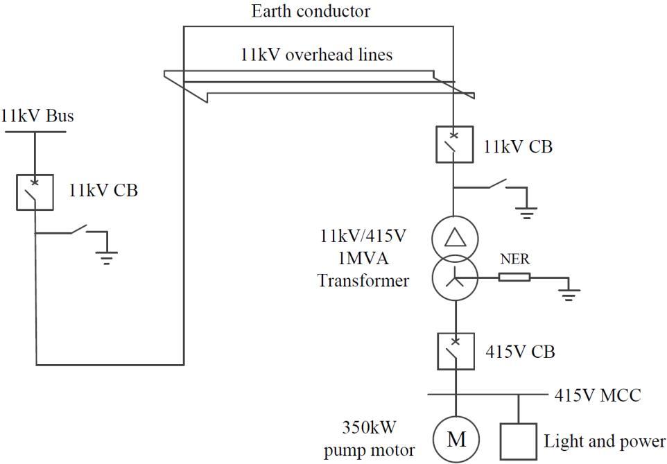
d) What would your process describe in the event that the high voltage circuit tripped again during re-closure?
Open and isolate 11kv circuit breakers. Investigate fault for the overhead lines. If there is no fault on overhead lines, then isolate the 11kV/415V transformer, inspect transformer protection relays and transformer 11kV terminations.
e) What differences would you have in your process in c) above, if this installation initially tripped on instantaneous overcurrent?
Do not re-close circuit breaker until fault is found or thorough investigation had been completed.
Mobile plant that will travel under the 11kV overhead lines: Dump truck, drill, excavator graders, etc. Equipment highest point is 9m (that is, truck with tray lifted) Line height needs to be at least 9 + 2.3 = 11.3m (refer to AS 3007 Table 7.1)
Open and isolate 11kV circuit breakers, investigate fault for the overhead lines. If there is no fault on overhead lines, then isolate the 11kV/415V transformer, inspect transformer protection relays and transformer 11kV terminations.
The following questions relate to a 6.6kV electric shovel installation supplied via trailing cable from a mobile substation.
a) Provide a single line drawing for the installation showing all protection devices from the substation to the shovel on board transformer. Detailing any assumptions made.
Refer to Figure 3.5 Typical 33/22/6.9kV mobile plant transportable substation with protection devices
b) What commissioning tests would you want performed on the installation prior to placing into service?
AS 3000 section 8 verification, AS2067 section 9 inspection and testing
Visual inspection: clearance between live parts, between live parts and earth. Functional test: verify operation of protective, monitoring and control, safety related devices, fire suppression system
Testing: cable earth continuity test, insulation resistance test, polarity check, operation of protection relays
c) Write an isolation procedure to allow access to the slip rings of the shovel.
At 66/22/6.6kV substation:
(1) Remotely open 6.6kV outlet circuit breaker, place permit lock.
(2) Close earth switch at outlet circuit breaker, place permit lock.
At 6.6kV shovel main disconnect switch: (3) Open main disconnect isolator, place permit lock.
(4) Close earth switch, place permit lock.
At shovel generator changeover circuit breaker: (5) Open generator changeover circuit breaker, place permit lock.
At upper brake and lower air isolation valve: (6) Isolate by turning “upper brake & low air” isolation valve to “ON” position. Test all air has been bled from the brake and lower air system.
At 6.6kV slip ring: (7) Test de-energised. Apply working earths.
You are the electrical engineering manager at a coal mine that has dragline. You are at home when you are called on the phone through the night. The supervisor says to you that the draglines power supply had tripped. When it was re-energised the electrician noticed that the main 22kV SF6 withdrawable circuit breaker was making a crackling noise.
a) What would your instruction be?
Talk to electrician for sequence of events. Develop high voltage access permit, open and rack out circuit breaker. Check SF6 gas level and leakage. Check for sign of arc or overheating.
b) What could be the possible causes of the crackling noise? Arcing in SF6, due to SF6 low pressure or insulation failure; Arcing, corona or partial discharge between phases.
c) The site has decided that the circuit breaker requires replacement, though no circuit breaker carriage is available. What would the electrician need to check on the new circuit breaker to ensure it was suitable? The model number, circuit breaker testing certificate. Visual inspection and conduct testing for defects. Check SF6 level. Check mechanical interlocks working.
d) You are unable to confirm that the new circuit breaker has had any recent commissioning tests. Detail the minimum tests and parameters that you would have conducted and the results you would expect before allowing the circuit breaker to be used.
Insulation resistance test at 10kV: >100G٠Contact resistance test at 10A: <100��٠Earth switch continuity at 10A: <1000��٠Operational check. After installation, check polarity. CT secondary injection test for relays.
e) The new circuit breaker has been commissioned and is in place. Detail any further actions that may need to be completed and the expected results, to ensure the circuit breaker is able to be energised without failing?
Check there is no earth fault in dragline cable; Check circuit breaker protection settings; After closing the circuit breaker, check for noise. Record in trip register.
When dragline / shovel need to move to new location (from a few hundred meters to a few kilometres away), walking on generator provides flexibility as it saves handling trailing cables or frequent connection of trailing cables.

Four high voltage cable permits should be developed:
Before walk on generator:
HV cable permit #1 for disconnecting cable from substation at original location; HV cable permit #2: for connecting cable to generator.
After walk on generator: HV cable permit #3 for disconnecting cable from generator; HV cable permit #4 for connecting cable to substation at new location.
The following represents a number of typical electrical engineering scenarios that are encountered in a typical coal operation.
1. Determine the full load current on the primary side of the transformer when a 250kW DOL pump motor is installed. The transformer supplying the installation is a 1.5MVA 11kV/415V with an impedance of 5%. Make any necessary assumptions in the calculation.
Assume that the power factor of the motor is 0.8.
Motor full load KVA: �� = �� ���������������������� = 250/0.8 = 313������
Motor full load current: ������������ = �� √3�� = 313000 √3∗415=435.45��������
Current at transformer primary side: �������� =435.45× 415 11000 = 16.43��������
2. Calculate the short circuit current of a 1.5MVA 11kV/415V transformer which is connected DY11 with an impedance of 5.5%?
When shovel comes across cable towers, cables shall be taken off from the tower. A trench can be dug and cables from the tower can drop in trench to prevent damage.
Before energising electric shovel at substation at new location, the 6.6kV outlet protection settings shall be checked so that they align with protection setting sheet.
Select 1.5MVA as base, Fault level: ����= ���������� |������������| = 1.5������ 0.055��.��. =27.27������
Short circuit current: ������������ = ���� √3�� = 27.27������ √3∗11���� =1431.30��
3. You have three 3000kVA transformers with impedances of 5%, 6%, and 7 % respectively. What would be the resultant fault level on the secondary bus when connected in parallel to a 66kV supply with a declared fault level of 375MVA?
Select 3000kVA as base, System impedance: �������� = 3������ 375������=��0.008 ��.��.
Per unit value for each transformer: ������1 =��0.05��.��. ������2 =��0.06��.��. ������3 =��0.07��.��. 1 ������ = 1 ������1 + 1 ������2 + 1 ������3 = 1 ��0.05+ 1 ��0.06 + 1 ��0.07 = 1 ��0.01963 ������ =��0.01963 ��.��. ������������ =�������� +������ =��0.02763��.��. |������������|=0.02763��.��. Fault level: ����= ���������� |������������| = 3������ 0.02763��.��. =108.6������
4. What CT ratio would you expect to be installed for a transformer primary installation that is rated at 4MVA 11kV with 5% impedance? (2 marks)
Transformer primary side full load current: ������������ = �� √3�� = 4������ √3∗11���� =209.95��������
CT ratio 1:300 would be OK (allows range up to 300A).
5. A 66/11kV transformer has a 20A Neutral Earth Resistor (NER) fitted (resistor only type rated for a duty of 10s), what would you expect the total resistance of this unit to be?
NER is connected between the transformer 11kV side start point and earth. �� = �� √3�� = 11���� √3∗20��=317.54Ω
6. You are in the process of designing a new power supply to three buildings on your site. The supply will be 11kV to a 1MVA (11kV/415V) transformer with an impedance of 6%. The design has considered additional loads from this transformer in the future with only one building being constructed now and two more in future years.
a) Determine what the maximum possible fault level at the 11kV transformer would be.
Select 1 MVA as base, Fault level: ����= ���������� |������������| = 1������ 0.06��.��. =16.67������
b) What would be the short circuit current on the secondary side of the transformer?
Short circuit current on the secondary side of the transformer: ������������ = ���� √3�� = 16.67������ √3∗415�� =23191.40��
c) The 415V secondary supply will be via a 80m 240mm² PVC cable from the building. Given that voltage drop (����) for this cable is 0.210 mV/A∙m, calculate the expected voltage drop over this length of run.
Assume the load of transformer is 25%. Full load current of the transformer: ������ = �� √3�� = 1������ √3∗415�� =1391.20��
Voltage drop: ���� =���� ∗������ ∗�� =0.00021∗345∗80=5.8�� (1.4% of 415V)
d) What in this installation would you consider to dictate the circuit breaker rating on the secondary side of the transformer for the building supply?
Short circuit protection settings: Short circuit settings ≤ 50% of short circuit current, i.e. ≤ 11595.7A
Overcurrent protection settings: This depends on the maximum load level of the building, typically 120% of full load current is set for overcurrent protection.
Earth leakage settings: Coordination should be considered for low level and high level earth leakage relays settings.
7. A substation has parallel transformer installation with two transformers 20MVA 66/11kV with 5% impedance. A bus tie is installed on the transformer secondary side, and load is supplied from the bus via a cable that that is 800m in length and has an impedance of 0.39 + j0.1Ω per km. The declared fault level on the line side of the transformers is 375MVA.
a) Draw the typical mining substation circuit described above using Australian Standard symbols. Show all the necessary hardware and protection devices you would require on this substation. Provide any assumptions made.
Figure 3.16 Single line diagram of the substation

b) Calculate the fault level and fault current at the end of the cable (i.e. at the load side of the 415V incomer) when the bus tie is open. Use a base of 5MVA for your calculation.
When bus tie is open: System impedance: ������������ = 5������ 375������=��0.0133
Transformer impedance: ���������� = 5������ 20������∗��5%=��0.0125
11kV Cable: �������������������� = (11����)2 5������ =24.2Ω ���������������� = (0.39+��0.1)∗0.8 24.2 =0.0129+��0.0033
Total per unit impedance: ���������������� =������������ +���������� +���������������� =0.0129+��0.0291 |����������������|=0.0318��.��.
Fault level: ����= ���������� |����������������| = 5������ 0.0318��.��. =157������
Fault current: ������������ = ���� √3�� = 157������ √3∗11���� =8240��
c) Calculate the fault level and fault current at the end of the cable (or at the load side of the 415V incomer) when the bus tie is closed. Use a base of 5MVA for your calculation.
When bus tie is closed: Transformer impedance becomes half (in parallel): ���������� = 5������ 2∗20������∗��5%=��0.00625
Total per unit impedance: ���������������� =������������ +���������� +���������������� =0.0129+��0.02285 |����������������|=0.0262
Fault level: ����= ���������� |����������������| = 5������ 0.0262��.��. =191������
Fault current: ������������ = ���� √3�� = 191������ √3∗11����=10016��
d) Under normal operating conditions, in what position would you want to see the bus tie? Explain the reasons why.
Under normal operating conditions, the bus tie needs to be open. When bus tie is open, the fault current is less (8240A opposes to 10016A), and short circuit settings can be set lower, or protection devices of smaller capacities can be selected.
Note that short circuit settings ≤ 50% of short circuit current. 8240��×50%=4120�� 10016��×50%=5008��
To be conservative, short circuit setting of CB 5 should be based on one transformer operation, i.e. to be set as 4120A, and remain the same setting 4120A no matter bus tie is open or closed.
3.10.1
You have been asked to supply and install a 415V motor for a new pump installation that is required to pump 60 litres or water per second up over a high wall of 150m vertically. The pump has an efficiency of 80% with a motor efficiency of 80% and power factor of 0.7 lag.
a) What will be the motor current of the pump installation? b) What size motor would you choose for this installation?
c) How much capacitance (in Kvar) needs to be added to get the power up to 0.95 lag? a) �� = �������� ���������������������� =60����∙������ 1 ∗9.8∗ 150��÷0.8÷0.8=143.5����
With a power factor of 0.7, ��=143.5����÷0.7=205������
The maximum motor current would be: �� = �� √3∗�� = 205������ √3∗415=285�� b) Choose a 220kW motor. 220kW is a standard motor size, 220kW > 205kVA, there is enough margin for the motor to operate. c) With a power factor of 0.7, ��0.7 =143.5����÷0.7=205������ ��0.7 =√��0.7 2 ��2 =√2052 143.52 =150��������
With a power factor of 0.95, ��095 =143.5����÷0.95=151������ ��095 =√��095 2 ��2 =√1512 143.52 =48��������
∆�� =��07 ��095 =150�������� 48��������=102��������
102 kVar of capacitance needs to be added to get the power factor up to 0.95.
3.10.2 Power factor correction for the whole mine site
The electrical supply to the coal mine is via two 33/11kV transformers. The maximum demand has been recorded as 20MVA at a 0.65 lagging power factor. a) Nominate the size of an 11kV connected capacitor bank to correct the power factor to 0.98 lag. Note: PFC units are available in 500kVAr increments. �� = 20������ ∗ 0.65 = 13���� ��065 =√��065 2 ��2 =√202 132 =√400 169=15.20�������� ��098 = �� 0.98 =13.265������ ��098 =√��098 2 ��2 =√13.26532 132 =√6.968=2.64��������
KVar required: ∆�� =15.20−2.64=12.56�������� PFC units are available in 500kVAr increments. Number of increments: 12.56 0.5 =25.12 Thurs, 26 increments of 500kVA capacitor banks are required to achieve power factor above 0.98.
b) What is the power factor achieved with the power factor unit you selected, at the nominated maximum demand? With 26 increments of 500kVA capacitor banks, 15.2��������−0.5��������×26= 2.2�������� ���� = �� �� = 13 √132 +2.22 =0.986
c) The capacitor unit is made up of three banks, delta connected. What is the kVAr value of each of the banks of capacitors?
Capacitor bank 1: 4 increments (0.5 × 4 = 2 MVar)
Capacitor bank 2: 8 increments (0.5 × 8 = 4 MVar)
Capacitor bank 3: 16 increments (0.5 × 16 = 8 MVar)
Now the power factor unit is designed with 7 steps, and each step additional 2MVar can be switched on.
Table 3.1 Switching steps of capacitor banks
Step Capacitor banks that switched on Reactive power that compensated
1 Bank 1 2 MVar
2 Bank 2 4 MVar
3 Bank 1 + Bank 2 6 MVar
4 Bank 3 8 MVar
5 Bank 3 + Bank 1 10 MVar
6 Bank 3 + Bank 2 12 MVar
7 Bank 3 + Bank 2 + Bank 1 14 MVar
d) Calculate the resultant power factor if the capacitor bank you selected remained connected when the demand dropped to 10MVA at 0.65 lag power factor. When demand is 10MVA at 0.65 power factor, �� = 10������ ∗ 0.65 = 6.5���� ��065 =√��065 2 ��2 =√102 6.52 =7.6�������� �� =7.6��������−0.5��������×26= −5.4��������
���� = �� �� = 6.5 √6.52 +5.42 = 0.77(leadingpowerfactor)
(With the design shown in Table 3.1, 28 increments were connected, PF = −0.71.)
e) List the relative merits of high voltage verses low voltage connected power factor correction units.
Power factor correction at high voltage side: As current is smaller at high voltage, conductors can be of smaller size; Capacitor banks can be located at HV substation, rather than at each individual motor control centres.

Power factor correction at low voltage side: Improved power quality at 415V MCC, and voltage drop is less in the 11kV cables that feeding 11kV/415V distribution transformer.
Figure 3.17 Proposed schematics for power factor correction unit
Contents
Topic 4.1 Electrical Protection Overview 53
According to AS/NZS 2081 Clause 1.2, the key objectives of this standard are listed below:
(a) The maintenance of touch and step voltage levels against time within acceptable limits;
(b) The minimization of risks associated with electrical arcing i.e. arc blast, arc flash, etc.
(c) Reliable performance under pre-determined operating conditions.
Topic 4.2 Earth Fault Protection 54
Topic 4.3 Earth Fault Lockout Protection 56
Topic 4.4 Earth Continuity Protection 57
Topic 4.5 Frozen Contact Protection 61
Topic 4.6 Neutral-connected Impedance Earth Fault Current Limitation 61
Topic 4.7 VSDs’ Impact on Electrical Protection 64
The requirements for the main forms of electrical protection include:
- Earth fault / earth leakage
- Earth fault lockout
- Earth continuity
- Frozen contactor
Figure 4.1 shows the typical arrangement of protection with IT earthing system, and this is widely adopted by surface and underground electrical mobile plants.

Topic 4.8 Protection Relay Certification and Compliance Requirements 66
Figure 4.1 Typical protection arrangements for electrical mobile plant
As is shown in Figure 4.1, mobile plant is supplied by 1.1kV cable. The earth fault lockout relay and frozen contact protection is located at the 1kV circuit breaker. The earth continuity (EC) relay monitors the earth continuity of the supply cable. The neutral earth resistor (NER) is between transformer star point and earth bar, and the NER Monitor monitors the integrity of the NER.
The primary earth leakage relay is located between the transformer and 1kV circuit breaker, and it trips the 1kV circuit breaker during fault; The back-up earth leakage relay is located at transformer star point, and it trips the 11kV circuit breaker feeding the transformer during fault. The trip current and/or trip time settings of backup earth leakage relay is much larger than that of primary earth leakage relay, for discrimination purpose.
Example protection settings for draglines and shovels are shown in Table 4.1.
Table 4.1 Example protection settings for draglines and shovels in an open cut mine
22kV P&H 9020 Dragline (peak power 23MVA)
6.6 kV Marion 8200 Dragline (peak power 16 MVA)
6.6 kV P&H 4100 Shovel (peak power 4MVA)
Current range 116 A 116 A 72 A
Current multiplier 4 4 2
Curve Extremely inverse Extremely inverse Extremely inverse
Time multiplier 0.1 sec 0.8 sec 0.8 sec
Current trip balance 50% 50% 50%
Short circuit trip setting 3 5 5
Short circuit trip time 80 msec 100 msec 80 msec
Back EMF time 30 sec 30 sec 30 sec
Earth continuity resistance trip 100 Ω 100 Ω 100 Ω
Earth continuity trip time 600 msec 600 msec 600 msec
Pilot latch ON ON ON
Earth fault sensitivity 300 mA 300 mA 300 mA
Earth fault time delay 230 mS 230 mS 230 mS
Earth fault lockout relay 15 MΩ 2 MΩ 2 MΩ
Earth fault lockout test time 10 sec 10 sec 10 sec
Under-voltage trip 50% 50% 50%
Note: Maximum cable length for the above mobile plants is 3000 metres.
4.2.1 Earth fault and earth leakage definition
Earth fault and earth leakage sometimes are used interchangeably while they are defined in AS 2081 as below:
Clause 1.5.11 Earth fault current
Current that will flow between an energized conductor and earth as the result of insulation failure.
Clause 1.5.15 Earth leakage current
Current that flows between an energized conductor and earth as the result of a reduction in the value of insulation resistance.
Clause 1.5.14 Earth fault protection Protection provided to detect earth fault current and initiate disconnection of the electrical supply from a fault zone.
4.2.2 Protection features
Clause 6.2 Operating values
Protection shall be capable of accurately sensing and initiating a trip for values of earth fault current ranging from < 0.1A up to 5A. The device shall have an accuracy of ±10% of the device set point value.
For earth fault protection devices installed on IT earthing systems, the minimum recommended trip ratio between the earth fault limitation device and earth fault trip value is Ten.
For example, the NER limits the earth fault to 5A, and the earth fault tripping value should be 500mA.
Clause 6.3.2 Instantaneous trip time
The instantaneous trip time of the protection device shall be no greater than 50ms.
AS 2081 recommends a maximum time delay for an earth fault should not exceed 500 msec. However, there are circumstances may this value have to be exceeded.
It may be necessary to provide longer time delay settings to allow for effective discrimination of tripping where multiple layers of protection exist within a supply network.
Meanwhile, it needs to be confirmed that the touch voltage and the duration is within the acceptable touch potential level.
As is shown Figure 4.2 and Figure 4.3, The main (primary) earth leakage relay is set as 500 mA, 350 msec, and it will be able to trip the 415V 4000A Terasaki AR440S circuit breaker;
The backup (secondary) earth leakage relay is set as 500 mA, 500 msec, and it will be able to trip the upstream 11kV circuit breaker and 11kV/415V transformer.


Figure 4.2 An example of earth leakage relay for main circuit breaker (Ampcontrol® ELDV2 - the green knob to adjust the trip level, and the red knob to adjust the trip time)
Figure 4.4 E/L relays and 415V 4000A Terasaki AR440S circuit breaker

Earth fault protection devices shall latch when tripped and remain in this state until reset.
The latch shall not reset on loss of power supply to the earth fault protection device.
It shall not be possible for the resetting mechanism, when held in the reset position, to override the tripping operation.
All fault trips shall be manually reset: automatic resetting is not permitted.
1. For an earth fault lockout device, what is the minimum permissible insulation resistance between a phase conductor and earth?
Earth fault lockout protection devices shall be designed to prevent energization of the circuit interrupting device when the insulation resistance of any active conductor to earth is below 1 MΩ.
2. What tests shall be successfully completed prior to energizing circuit?
Clause 7.3 Sequence of tests prior to energizing circuit
(a) ELV earth fault lockout test
(b) Non-extra low voltage insulation test (where applicable). This test shall be conducted only while the earth continuity circuit remains healthy.
3. What are the requirements for latch/reset facility of earth fault lockout protection devices?
Earth fault lockout protection devices shall latch when tripped and remain in this state until reset.
The latch shall not reset itself on loss of power supply to the earth fault lockout protection device.
It shall not be possible for the resetting mechanism, when held in the reset position, to override the lockout operation. All fault trips shall be manually reset: automatic resetting is not permitted.
4. Why the earth fault lock out relay needs to be Ex i (intrinsically safe)?
Earth fault lockout protection devices are intended to undertake a test of the insulation of the power conductors to earth of an outgoing circuit. The initial test that is undertaken is an ELV, low energy test. If a fault exists on the outgoing circuit, this low energy test will not create a hazardous situation of arcing and sparking. Any persons that may be present at the time of initiation of the test are unlikely to suffer burns or receive a shock as a result of the application of the extra-low test voltage. When used in hazardous areas of underground coal mines, these test voltages must be intrinsically safe.
A successful ELV test of the cable should then be followed by a high voltage test. The high voltage test is more likely to identify any incipient faults associated with the insulation of the power conductors.
AS 4871.1 Clause 3.4.5 can also be referred:
Clause 3.4.5 Earth continuity and earth-fault lockout protection in hazardous zones
For the applications in Clause 3.4.3 and 3.4.4 it is possible that earth continuity and earth fault lockout systems used in a hazardous zone may be energized in a cable or machine that is located in an area outside the area containing the supply outlet and which may contain a high level of methane. These systems should be certified to Ex ‘ia’ standards.
Where a mine is able to demonstrate that it is not possible for these circumstances to exist at their mine, then Ex ‘ib’ certification may apply. A suitable warning label (see Clause 5.4) shall be fitted adjacent to outlets.
AS 2081 and AS 4871.1 provide requirements for the application of earth continuity (EC) protection in earth fault limited mining systems, e.g. cables of draglines, electric shovels, continuous miners etc.
A fundamental requirement in both AS 2081 and AS 4871.1 is that the EC protection is capable of monitoring incremental changes in the resistance of the earth return path to ensure that leakage currents do not result in dangerous touch voltages.
1. What is the maximum permissible operating time for an EC protection device? Why is this maximum time important?
5.3
The device shall be capable of implementing an operating time of 100 ms. Provision may also be made for adjustment of the operating time to a maximum of 500 ms.
To ensure the power is isolated from the circuit prior to separation of the power pins in couplers, receptacles and the like, the maximum delay between the detection of an earth continuity fault (open circuit or short circuit) and the disconnection of power from the circuit should not be more than 500 ms.
This operating value is equal to the duration of touch voltage in the event of electric shock, so the shorter operating value would be safer to personnel.
2. Earth continuity protection devices shall be designed to operate if the shunt resistance between the pilot and earth falls below a nominated value. What is this value?
Clause 5.2.3 Shunt resistance value
Pilot core and earth cannot be short-circuited. If the resistance between a pilot core and earth falls below 1 kΩ, the device shall initiate the tripping or prevent the closure of the circuit interrupting device. The device shall indicate earth continuity short-circuited.
3. AS2081 nominates a typical maximum EC resistance setting of 45Ω. In determining the relay setting – what are the crucial parameters that need to be considered?
Relay operating time, relay operating resistance; Shunt resistance between pilot and earth that will trip the relay. (Other things to be considered: Earth resistance and the potential rise during earth fault; Pilot resistance per km and cable length.)
4. Where remote start functionality is provided via a pilot circuit, what condition is required to be prevented, and how is this achieved?
Clause 5.6 Pilot circuit voltage withstand
Where a pilot wire is utilized, the occurrence of a pilot-to-earth or a phase-to-pilot fault shall not result in an unsafe failure of the device.
5. What indications shall EC protection device provide while it is in operation?
Clause 5.7 Indication
While in operation the EC protection device shall be provided with a means for indicating the following state:
(a) Power ON.
(b) Earth continuity healthy.
(c) Earth continuity open-circuited. (d) Earth continuity short-circuited. (e) Start button time out (only required where remote start option provided). (f) Pilot control operation (only required where remote start option provided).
6. EC resistance maximum settings is 45Ohms, but it may not be appropriate. Why?
This upper value of possible earth resistance, allowing for known pilot resistance of the cables, may result in potentially dangerous voltages appearing at a machine. Measures should be used to ensure that the machine cable’s earthing resistance remains as low as practical rather than potentially operating at the upper limits of the pilot relay.
Example 1 (from AS4871.1 Appendix C)
Earth-continuity protection devices shall be designed to operate when the earth return path resistance exceeds the resistance value selected on the device. Calculate the pilot-earth resistance for 250m long Type 241 cable (35mm², with earth conductor 1.094 Ω/km) and determine the EC protection settings.

Pilot resistances (data from AS1802 clause 8.1):
Cable size Pilot resistance
Cables ≤ 35 ����2 55 Ω /km
Cables > 35 ����2 30 ٠/km
Earth continuity relay specifications from OEM: Component Operating time
Vacuum contactor 130ms Interposing relay 20ms
Earth leakage relay (excl. intentional delay) AS2081 6.3.2 Instantaneous trip time 50ms Total Operating Time 200ms
Pilot resistance: ������������ = 55×0.25=13.75 Ω
The total operating time from the earth leakage relay identifying that a fault exists to the fault actually being cleared is 200ms. As seen in Figure 4.11, the allowable maximum touch voltage could be at 110V.
Figure 4.6 Maximum Duration of Prospective 50Hz Touch Voltage (Copyright AS 3000: 2018)
Figure 4.5 Mining electrical system with fault (Copyright AS4871.1 Appendix C)

(a) The dropout EC value of the relay is fixed at 45 Ω. Allowing for the resistance of the pilot circuit (13.75 Ω), resistance of the earth return path cannot exceed: ����������ℎ =������������ ������������ =45Ω 13.75Ω = 31.25 Ω
With this value of earth resistance and a maximum touch voltage of 110 V, the maximum safe current limit cannot exceed: 110��/31.25٠= 3.52��
Commonly available values of resistance for the neutral earth resistor (NER) limit current to 2 A and 5 A. Therefore, for this installation, a 2 A NER should be chosen, as 2 A < 3.52 A.
If a 150 ����2 type 241 cable, 660 m long, was to be used, pilot resistance would equal 19.8 Ω. Earthing conductor resistance is given as 0.387 Ω /km for this cable.
Calculate the correct earth protection component values as follows:
(a) The dropout EC value of the relay is fixed at 45 Ω. Allowing for the resistance of the pilot circuit (19.8 Ω), resistance of the earth return path cannot exceed 25.2 Ω. With this value of earth resistance and a maximum touch voltage of 110 V, the maximum safe current limit cannot exceed 4.37 A.
Therefore, for this installation, a 2 A NER should be chosen.
(b) If it was decided to use a 5 A NER, the maximum allowable value of resistance of the earth return path would be: 110��/5�� = 22Ω
The pilot/earth-loop resistance would be: ������������ =������������ +����������ℎ =22Ω + 13.75Ω= 35.75 Ω
Therefore for this installation, an earth-continuity relay should be chosen that operates at a resistance value of 35 Ω.
As the pilot resistance increases, the quality of the earth return path must improve (lower resistance) to ensure that the 45 Ω pilot–earth loop resistance is not exceeded. (b) If it was decided to use a 5 A NER, the maximum value of resistance of the earth circuit would be 22 Ω. 22 + 19.8 = 41.8Ω
Therefore, for this installation an earth-continuity relay should be chosen that operates at a resistance value of 40 Ω.
In 2016, Ampcontrol® released a White Paper ECM3 - A Fresh Look at Earth Continuity, Safety and AS/NSZ 2081 Compliance. The below is cited from this White Paper:
In practical applications, environmental factors often prevent an earth continuity protection system from complying with both requirements of AS 2081 and AS 4871. Affecting factors can include coupled noise onto the pilot of the cable, variation in the resistance of the pilot cable due to temperature, and the overall length of the cable.
Cable structure, supply harmonics and installation arrangement are several potential sources of noise on the pilot circuit. Non-symmetrical cables are used in many installations, resulting in the supply voltage from two of the three phase cores being coupled to the pilot core. In addition to this, noise on the phase conductors of a cable can also be coupled onto the pilot core, regardless of cable type. Dirty slip rings in cable reeling systems also provide a source of noise on the pilot circuit.
Noise on the pilot circuit interferes with an earth continuity relay’s ability to reliably detect an earth continuity fault. It can also result in nuisance tripping, especially when the healthy pilot.
Although AS 4871 notes 45Ω as the maximum tripping threshold for the pilot/earth return path impedance in underground applications, in many surface installations this impedance value is much too low to be practical. It is common for surface installations to have cable lengths of up to 8km, with the pilot resistance alone on these cables exceeding the recommended underground limit of 45Ω. It is common for surface earth continuity relays have a tripping threshold of 100Ω.
Although the higher tripping threshold of 100Ω allows for installations with long cables, installations that require lower healthy pilot/earth loop impedances have a much larger disparity between the healthy impedance and the tripping threshold. It is common for a fixed trip threshold of 100Ω to result in non-compliant (arguably dangerous) touch voltages.
Earth continuity protection ECM3 relays use static time and trip settings. Using these relays, it is sometimes not possible to achieve a practical earth continuity
protection system that satisfies both the requirements of a fast trip during a live uncoupling, and preventing dangerous touch voltages developing during earth leakage faults.
In these scenarios, the use of a dynamic trip threshold in the form of a “dynamic trip time response” would allow a fast trip during a live uncoupling as well as provide a slower trip during high impedance readings, providing noise immunity.

Ampcontrol has developed an innovative method of earth continuity protection in the form of the Ampcontrol ECM3 Protection Relay. This new relay utilises an “impedance versus trip time response” to provide discrimination between an open circuit and a gradual increase in the measured pilot/earth loop impedance of the protected cable.
As is shown in figure 4.7, during an open circuit or large impedance increase, the ECM3 will trip very quickly; If the impedance of the pilot/earth loop exceeds the tripping threshold by a small amount, then the ECM3 will trip at a slower rate.
Figure 4.7 Tripping characteristic of ECM3 EC relay (Copied from Ampcontrol® White Paper ECM3 - A Fresh Look at Earth Continuity, Safety and AS/NSZ 2081 Compliance)
The slower tripping time at the lower earth continuity fault levels allows the tripping threshold to be set much closer to the impedance of the healthy pilot/earth loop circuit, thus allowing the ECM3 to prevent the development of dangerous touch voltages as required by AS 4871.
1. What are the operating values and operating time requirements for frozen contact protection?
The protection device shall be designed to initiate a trip of an upstream circuit interrupting device if a voltage exceeding 25 V a.c. or 60 V d.c. is detected on any phase on the load side of the circuit interrupting device when it is expected to be in the open position.
The device may also have adjustable trip setpoints that allow for voltages up to 10% of the nominal supply voltage to be detected on any phase of the load side of the circuit interrupting device before initiating a trip of the upstream circuit interrupting device.
The protection device shall be designed to initiate a trip of an upstream circuit interrupting device if the mechanical state of the circuit interruption device is different to that expected. For example, if the auxiliary interlocks have not changed state although the interruption device has been signalled to energize or de-energize.
The operating time to initiate a trip signal shall be as follows:
(a) For Clause 9.2.1 Load side voltages, be adjustable between 1 and 20 seconds.
(b) For Clause 9.2.2 Contact states, not exceed 1 second. This shall be measured immediately following the receipt of an open or close signal for the circuit interrupting device.
Following the opening of a circuit interrupting device and expiration of the time period nominated in (a), the frozen contact protection device shall revert to a maximum 1 s delay on the initiation of a trip signal, if voltage is detected on any load side conductor of the circuit interrupting device.
2. For Frozen Contact Protection, a trip time of up to 20 seconds is permitted for detection of voltage on the load side of a contactor after it is expected to be in the open position. Under what circumstances would such a long trip time be required?
In cases of high inertia loads are supplied, there will be a back EMF from the motor after it is de-energized. In these cases, the device can be configured to ignore the back EMF for a period not exceeding 20s.
In an IT earthing system, the neutral earth resistor (NER) is located between star point of transformer and earth bar. Depending on the design, the NER limits the earth fault to 5A, 10A or 25A (25A is the maximum). This earth fault limitation not only greatly reduce the touch potential for personnel, but also ensures that the fault current is not high enough to ignite explosive gas/dust in hazardous areas.
The location of NER and designated earth fault loop is shown in Figure 4.8.
4.8
fault loop in IT system, and earth fault is limited by NER
Note that in IT earthing system, the neutral conductor is not included in supply cable. Suppose the supply cable has neutral conductor (shown in Figure 4.9), if the neutral conductor is damaged and contact earth, the NER will be bypassed in the event of phase-to-earth fault, and the fault current is no longer limited to 5A.
Though the primary earth leakage relay will pick up the earth fault, the backup earth leakage relay will not be able to see the earth fault.
Figure 4.9 Earth fault-loop in IT system with neutral to earth fault, and NER is bypassed during phase to earth fault (Neutral conductor shall NOT exist in IT system)
The integrity of NER needs to be monitored by NER monitor relay. This requirement can be found in AS 2081 Section 8 and AS 3007 Clause 3.5.
A decrease in the resistance of the NER will result in an increase in the earth fault current. This will result in an increase in prospective touch or step potentials under fault conditions.
An increase in resistance of the NER will result in a decrease of the earth fault current. Though this will result in a decrease in the prospective touch or step potentials, it will reduce the likelihood of the earth fault protection system initiating a trip of the protection devices.
Table 4.2 Preferred earth fault current limitation currents (Table copied from AS 3007 Appendix F)
System voltage (kV)
Earth fault current limitation (A) Impedance (Ω) 66 200 190 33 180 106 22 25 508 11 25 or 10 254 or 635 6.6 25 or 10 152 or 381 3.3 5 381
Figure 4.10 and Figure 4.11 shows the location of the NER enclosure; Figure 4.12 shows a typical NER monitor relay.
Figure 4.10 NER located between transformer secondary side star point and earth

For neutral-connected impedance earth fault current limitation devices, to be rated for the stated earth fault current at the rated phase to earth system voltage. This can be a short time (10-second) rating.

However, the use of a short time rated NER can lead to a specific problem, particularly where the connected load includes multiple VSDs. High frequency earth fault currents can be significantly higher than the value of NER current limitation.

Safety Bulletin SB11-04 - Electrical Hazards Associated with VSDs and Earth
Fault Current Limited Systems was released by NSW resource regulator. The below contents are copied from this safety bulletin:
VSDs often cause relatively large capacitively coupled currents to flow in the earthing systems of the associated drive motors during normal operation. These capacitive currents are associated with the switching frequencies of the output of the VSDs.
These high frequency currents are a source of electro-magnetic interference (EMI or noise) that can cause unreliable and sporadic operation of electronic control equipment. To minimise the impact of this noise on surrounding plant and equipment, it is common practice to use filter circuits to localise the currents to a specific area of the electrical network.
However, the use of VSDs and associated EMI mitigation techniques may (in certain circumstances) have a detrimental impact on the effectiveness of the current limitation system as used in underground mines. This phenomenon appears to be amplified when two or more machines fitted with VSDs and EMI filters are supplied from the one substation/transformer which utilises a neutral earthing resistor (NER).
Recent incidents at an underground mine involving earth faults on motor cables fed from VSD drives have drawn this issue to the Department’s notice. Investigations into these incidents have identified high frequency currents flowing to earth during these fault conditions which were significantly higher than the value of the current limitation of the NER for the supply system.
Computer modelling has indicated that when powered from a common supply, the combined effects of multiple VSDs and EMI filters during fault conditions on the load side of the VSD can excite resonances that cause large circulating currents to flow between the EMI filters. Elements of this modelling have been verified in actual tests of equipment presently in service. Modelling also suggests that currents of several times the maximum value of the limitation device can flow at the substation NER.
Therefore, during an earth fault on the output side of an operating VSD higher fault currents could also have the effect of generating higher than expected
prospective touch potentials at machinery associated with the supply system, not just at the location of the earth fault. There is also an increased risk of sparking between machines, if machines are in close proximity to each other at the time an earth fault occurs on the VSD supplied motor or cable.
1. It should be noted, that the duration of these high current earth faults on the equipment tested so far is typically very short. Tests on this equipment have demonstrated clearance times of about of 1 msec, due to the operation of an EMI filter fuse utilised with this system. However, different VSDs should be modelled according to their unique fault level and/or clearance time characteristics, where interactions with other VSDs and their associated EMI filters is possible.
2. Where a machine is fitted with its own isolation transformer e.g. the VSD traction drives on a longwall shearer the EMI filter on these drives will not interact with any other VSD drives in the longwall panel.
(1) The values for the earth continuity of machinery fed via reeling and trailing cables, where VSD drives are utilised, need to be maintained at a minimum value This is the primary protection against excessive touch potentials and should also be considered best practice in normal mining environments.
Note: The normal value for tripping of earth continuity relays is 45Ώ. This upper value of possible earth resistance, allowing for known pilot resistance of the cables, may result in potentially dangerous voltages appearing at a machine. Measures should be used to ensure that the machine cable’s earthing resistance remains as low as practical rather than potentially operating at the upper limits of the pilot relay.
(2) Equipment fed via reeling or trailing cables should be protected with earth leakage units set for no intentional time delay i.e. ‘instantaneous’ initiation of fault detection.
(3) The length of all reeling and trailing cables, including those supplying DCBs and Distribution Boxes should be kept as short as possible. Relocation of transformers should be undertaken where possible, in preference to the use of extension cables to machinery.
(4) Effective mechanical protection should be provided to all cables fed from a VSD drive to minimise the likelihood of damage to the cables.
(5) Where possible rearrange the VSD operated machinery at the mine to minimise the number of VVVF drives and associated EMI filters with any single substation/transformer e.g. distribute VSD operated equipment evenly between underground panels where such equipment does not have its own onboard isolation transformer.
(6) Where a mine utilises VSD drives supplied through trailing cables it is suggested that the operator of the mine consider having software modelling of their applications undertaken to determine the extent to which the safety at the mine may be affected by this issue and how the risks can be managed.
(7) Reference for further information:
AS 4871.1:2010 Appendix E Variable speed drive - guidance for identification of potential risks
Table 4.3 Potential hazards associated with VSDs and guidance (Table copied from AS 4871.1: 2010 Appendix E)
You have recently taken over as the electrical engineering manager and you have identified that your mine has taken no action concerning the recommendations of Safety Bulletin SB11-04 Electrical Hazards Associated with VSDs and Earth Fault Current Limited Systems.
You have brought this to the attention of the Mine Manager who has asked you to develop a strategy and identify what further actions the mine should take. Your mine currently has:
A new longwall on order with the shearer fitted with VVVF drive traction control; Three development sections each with a continuous miner and two shuttle cars all fitted with VSDs.
Develop an action plan with anticipated time frames, including:
• Who you will involve in the process
• In relation to the recommendations in the Safety Bulletin, what the identified issues are likely to be
• Identification of the risks associated with this type of technology when used with an “IT” earthing system in an underground coal mine
• How you intend to communicate the issues and outcomes, and to whom these will be communicated
Earth fault on the load side of VSD may excite resonance within power EMC filters resulting in large circulating currents between machines.
Where multiple power EMC filters are fed from a single substation, modelling should be undertaken of the effects of earth faults at different locations to identify any currents that may flow throughout the earthing system of the secondary side of the substation, and the general mass of earth. Modelling must consider the switching frequencies of all VSDs connected to substation
Table 4.4
Resonance associated with fault on the load side of VSD and associated power EMC filter may result in currents flowing in a NER greater than the designed current limitation value.
Earth faults on the DC bus of a VSD may result in currents flowing in the NER of a substation with a value greater than the designed current limitation value
Thermal rating of NER at the substation should be verified against the requirements of AS 2081:2011, allowing for currents that exceed the designed current rating of the NER may result from resonant conditions.
Issue Action By who Due date Specification, location and quantity of VSDs are unknown
Conduct an audit for VSDs, identify further issues and work out a plan to rectify. Minimize the quantity of VSDs if possible.
Electrical Engineer 2 weeks
Fault currents frequency and magnitude unknown
Cable is not well protected and cable damage incident occurs often
Conduct computer modelling for VSDs with EMI filters during fault conditions and provide recommendations.
Provide adequate mechanical inspection for cables, assign task to inspection cables per shift
OEM or specialist 2 weeks
Electrical supervisor 2 weeks Protection settings (e.g. earth leakage trip time) are not safe
Review protection settings for drives with VSD and amend settings
Electrical Engineer 2 weeks
There is no inspection sheet for VSDs and EMI filters
No maintenance plan for VSD and EMI filter inspection
EMI filter and fuses are not inspected after each cable earth fault.
Develop inspection sheets for VSDs, EMI filters and fuses. Electrical Engineer 2 weeks
Develop maintenance plan for VSDs, EMI filters and fuses. Maintenance Planner 2 weeks
Amend restoration of power procedure, add inspection of EMI filter and fuses after each cable earth fault.
Electrical Engineer 2 weeks
Integrity of NER is not monitored Install NER monitoring device Electrical supervisor 6 weeks
Note: EMI filter is installed in parallel with the motor. Earth fault current in cable often cause EMI filter fuses blow up. This does not affect the motor, but often causes earth leakage trip on other motors.
1. It is required that a relay designed to comply with AS 2081 shall have independent verification or certification.
As is described in clause 1.7, two categories of tests are recognized:
(a) Type tests, the purpose of which is to establish that the design complies with this Standard.
Type tests shall be in accordance with AS 2081 Section 10. List and order of tests are shown in AS 2081 Table 10.1.
(b) Routine tests by the manufacturer on the protection device to demonstrate consistency of the manufactured product against the type tested design. Routine tests shall be in accordance with AS 2081 Section 11. Routine tests are shown in AS 2081 Table 11.1
No adjustment shall be possible that allows the protection device to operate outside the limits set in this Standard.
Where the protection device has adjustable parameters and/or a calibration facility, provision shall be made for access to such adjustments to be restricted.
3. What information that should be included on the label of a protection device?
2.13.1
The identity of each protection device shall be visible when mounted in its service position (but not necessarily energized).
The protection device shall also be marked in a legible and durable manner with the following additional information:
(a) Name or registered trademark of the manufacturer, or that of the manufacturer’s agent where the agent is the holder of the certification or approval.
(b) Catalogue number, type number, or other identification marking.
(c) Function of device, e.g. ‘earth-continuity relay’.
(d) Compliance to the relevant section(s) of this Standard.
(e) Hazardous area certification markings, if the device is intended for use in hazardous areas.
(f) Where required, the identification of associated ancillary equipment (such as current sensing transducers).
(g) The voltage, current and VA rating of the device output contacts.
(h) Device supply voltage and frequency (nominal value ±% tolerance).
(i) Where applicable, a manufacturer shall provide a means of identification of the program or software version associated with a specific device.
4. Protection devices shall be designed so that normal operation remains unaffected due to variations in the control power supply voltage. In the event the control supply voltage drops to 50% of its nominal value, how long should the device continue to operate normally?
The protection device shall be designed so that its normal operation remains unaffected while the control power supply voltage is varied within the range of 75% to 120% of the nominated supply voltage.
2. What limitations does AS2081 impose on the adjustment of relay parameters?
The device shall continue to operate correctly for at least 2 seconds after the supply voltage is reduced to 50% of its nominal voltage.
Sets
Contents
Topic 5.1 Protection Against Electric Shock 67
Topic 5.2 Earthing and Earth Bonding Requirements 68
Topic 5.3 Single phase generators under 25kW supplying socket outlet 69
Topic 5.4 Single phase generators under 25kW supplying fixed installation switchboard 73
Topic 5.5 Three phase generators above 25kW with IT and TN earthing system 75
NSW DPI EES-014 Technical Principles for the Use of “Stand Alone” Generators at NSW Mines (Coal and Metals) and Extractives Operations provides a guide on the selection and connection of stand-alone generators.
NSW DPI EES-014 Section 2.1
For protection against indirect contact, protection can be by a combination of either/or:
• Automatically disconnecting supply under fault conditions
• Using Class II equipment
• Electrical separation
If automatic disconnection is chosen, a system must be provided in which all external conductive parts are electrically bonded; with some systems also being effectively earthed with an earth electrode. Automatic fault disconnection is provided via circuit breakers, fuses, RCD etc.
If electrical separation is chosen, the generator is treated the same as an isolation transformer, with the installation isolated from earth. In this configuration an RCD will not operate and therefore is not used (AS 3000 Figure 7.7 Note 4: An RCD cannot be fitted, as the equipotential bond is connected to the frame of the generator). Such systems can provide increased protection for Class II (double insulated) equipment.
AS 3010’s requirements for generator’s earthing and bonding are provided below:
Clause 2.8.1
The generating set earthing and earth bonding arrangements shall be as follows for neutral-earth connected generators (for other earthing systems, see Clause 2.11.3):
(a) The neutral to frame link in the generating set shall be permanently removed.
(b) An earth cable in accordance with AS/NZS 3000 requirements for the main earthing conductor shall be installed from the electrical installation to the generating set and connected to the generating set earth bonding connection and the main switchboard earth bar.
(c) An electrical installation earth electrode and main earthing conductor in accordance with AS/NZS 3000 requirements shall be provided for the electrical installation and connected to the main switchboard.
2.8.3
1. The ‘star’ point or neutral connection of a multiple-phase output isolated winding
2. One output connection of a single-phase isolated output winding. The output connection to the generating set bonding system shall be by means of a permanently labelled removable link mounted adjacent to the generating set A.C. output connections.
3. Engine frame
4. The generator or alternator frame. All exposed conductive parts enclosing electrical equipment or wiring.
5. The earth terminals of any socket outlets.
6. The frame connection.
b) What specific items would you want addressed in your site layout with respect to the electrical installation?
Interaction with cables, interaction with refuelling
Clause 2.11.3 Other systems of supply
Alternative systems of supply are permitted, and shall be in accordance with AS/NZS 3000.
NOTE: The detailed requirements for other systems of supply are outside the scope of this Standard.
MEN stands for Multiple Neutral Earth, which is widely used in residential supplies.
Mine site typically NOT use Multiple Neutral Earth, but use solid earth, i.e. run earth cable to every electrical equipment.
MEN link at mine site should be called “Neutral-Earth Link”.
You are the electrical engineering manager and a contractor has a requirement to construct a temporary compound for offices and storage containers. The offices and containers will be supplied via a 250kVA Generator.
a) What specific items would you want addressed in your site layout with respect to the electrical installation?
Interaction with cables, interaction with refuelling
b) Is there anything in particular you would require for the water tank installation or storage containers?
An external equipotential bounding conductor should be run.
c) On the attached layout drawing, detail the earthing arrangements you would require for the entire installation and show any specific details and assumptions.

Note: This configuration shall only be used where a need has been identified for “Electrical Separation”.
Figure 5.1 Generator with integral RCD protected socket outlet
Figure 5.2 Protection via Electrical Separation as per AS 3000: 2007 Section 7.4


• This is preferred configuration for small portable generators where electrical separation of the supply to earth is not required.
• For plug & sockets connected to generators, the connection of a generating set bonding system to the general mass of earth though an earth electrode is not required or recommended.
• Where a powered appliance is to be used with an extension lead, an additional 2.5mm2 equipotential bond should be run to any un-bonded metal work associated with the use of that appliance.
E.g. When using a power tool on a light vehicle, the metal body of that vehicle should be equipotentially bonded back to the generator.
• This configuration must NOT contact earth, an electrode, electrical earthing system or any other extraneous conductive parts of equipment (either intentionally or accidentally), such as conveyor belt structures, metal piping etc. Refer to AS 3000:2007 Clause 7.4.6.
• Exposed metal parts of mains powered equipment must NOT be simultaneously accessible with exposed metal parts of the generator fed equipment.
• To achieve “best practice” all extension leads used in a mining environment must be screened leads and fitted with IP56 plugs and sockets. The screen of extension leads MUST be connected to the earth terminals at both the plug and sockets ends.
• To achieve “best practice” all extension leads used in a mining environment must be screened leads and fitted with IP56 plugs and sockets. The screen of extension leads MUST be connected to the earth terminals at both the plug and sockets ends.
N.B. Screened extension leads should be removed from service if the metal screen is exposed to the environment due to sheath damage.
• For additional protection, IP56 rated plugs should be fitted to any tools.
• For additional protection, IP56 rated plugs should be fitted to any tools.
• The preferred rating of the permanently connected RCD is 10mA. The maximum rating of the RCD shall not exceed 30mA.
• The RCD shall operate in all live conductors (active and neutral).
• The use of an RCD with this configuration will not contribute to the safety of the installation, and is not permitted. Refer to AS 3000:2007 Fig 7.7 Note 4.
• While two pole switching of the socket outlets is preferred, switching of active conductors only of socket-outlets is permitted because of the neutral-to-frame connection on the generator side of the RCD (See note in AS 3010:2017 Fig 4.3).
-
-
• Two pole switching of the socket outlets is required.
• The supply cable between the generator and the switchboard must be protected against short circuit faults. If this protection is not built into the design of the generator, a suitably rated circuit breaker (or fuses) will be required.
• Only one item of Class I or one item of Class II electrical equipment is to be connected at any one time to this generator.
• Power boards must not be used with this configuration.
- Maintenance of the generator, extension cables and tools used with the generator is critical to the safe operation of this configuration. Regular testing to AS3000:2007 Clause 7.4.7 (insulation and earth bonding tests) is essential for the continued safe use of this type of equipment.
Figure 5.1 Generator with integral RCD protected socket outlet
Figure 5.3 RCD protected inverter for use with multiple items of Class I or Class II portable tools
• This is preferred configuration for small portable generators where electrical separation of the supply to earth is not required.
• For plug & sockets connected to generators, the connection of a generating set bonding system to the general mass of earth though an earth electrode is not required or recommended.

• Where a powered appliance is to be used with an extension lead, an additional 2.5mm2 equipotential bond should be run to any un-bonded metal work associated with the use of that appliance.
E.g. When using a power tool on a light vehicle, the metal body of that vehicle should be equipotentially bonded back to the generator.
• To achieve “best practice” all extension leads used in a mining environment must be screened leads and fitted with IP56 plugs and sockets. The screen of extension leads MUST be connected to the earth terminals at both the plug and sockets ends.
• For additional protection, IP56 rated plugs should be fitted to any tools.
• The use of an earth stake is NOT recommended.
• Where a powered appliance is to be used with an extension lead, an additional 2.5mm2 equipotential bond should be run to any un-bonded metal work associated with the use of that appliance.
E.g. When using a power tool on a light vehicle, the metal body of that vehicle should be equipotentially bonded back to the generator.
• To achieve “best practice” all extension leads used in a mining environment must be screened leads and fitted with IP56 plugs and sockets. The screen of extension leads MUST be connected to the earth terminals at both the plug and sockets ends.
• For additional protection, IP56 rated plugs should be fitted to any tools.
• The RCD shall operate in all live conductors (active and neutral).
• The preferred rating of the permanently connected RCD is 10mA. The maximum rating of the RCD shall not exceed 30mA.
• Every sub-main or final sub-circuit outgoing from an electricity converter shall be individually protected with an RCD.
• The preferred rating of the permanently connected RCD is 10mA. The maximum rating of the RCD shall not exceed 30mA.
• The RCD shall be of a type suitable for the waveform of the particular inverter, and in accordance with the inverter manufacturer’s recommendations.
• Circuit protection (from AS 3000 Clause 4.12.5.2).
• While two pole switching of the socket outlets is preferred, switching of active conductors only of socket-outlets is permitted because of the neutral-to-frame connection on the generator side of the RCD (See note in AS 3010:2017 Fig 4.3).
-
A permanent generator feed is one that is in place of a mains supply for an extended period of time. This is intended for installations where there is no mains supply available.
A temporary generator feed is one that is replacing a mains supply while the mains supply is unavailable. This is intended for maintenance related activities associated with the mains supply that cause limited interruption to the mains supply.
Figure 5.4 Permanent low voltage connections from stand along single phase generator to a fixed installation switchboard

Figure 5.5 Temporary low voltage connection from a stand-alone single phase generator to a fixed installation switchboard
• AS3010 Clause 2.8.3 Generating set bonding system
When the generating set is permanently connected to a switchboard by installation wiring in an electrical installation, the generating set neutral to frame link shall be permanently removed.
• The connection of a generating set bonding system to the general mass of earth through an earth electrode is not required or recommended (AS/NZS 3010:2017 Clause 4.3.2).
(AS3010 Appendix A explains the reasons why an earth electrode is not required or recommended to be connected to the generator set.)
• Where practicable, all the earthing points, other than for lightning protection, should be electrically bonded together (Refer AS/NZS 3000:2007 Section 5.8).
• The generator and switchboard should ideally be located as close as possible to each other. Alternately, an additional equipotential bond of the same size as the power conductors can be used between the generator casing and the switchboard.
• The earth stake installed to AS/NZS 3000:2007 Section 5.3.6 at the main switchboard may be left in place while the generator is connected in place of the mains supply.
• Where practicable, all the earthing points, other than for lightning protection, should be electrically bonded together (Refer AS/NZS 3000:2007 Section 5.8).

• Where a powered appliance is to be used with an extension lead, an additional 2.5mm2 equipotential bond should be run to any un-bonded metal work associated with the use of that appliance.
E.g. When using a power tool on a light vehicle, the metal body of that vehicle should be equipotentially bonded back to the generator.
• To achieve “best practice” all extension leads used in a mining environment must be screened leads and fitted with IP56 plugs and sockets. The screen of extension leads MUST be connected to the earth terminals at both the plug and sockets ends.
• For additional protection, IP56 rated plugs should be fitted to any tools.
• The only earth reference connection to the generator windings shall be made at the generator terminal box No MEN connection shall be made between the switchboard Neutral Link and the Earth Link.
-
• Where a powered appliance is to be used with an extension lead, an additional 2.5mm2 equipotential bond should be run to any un-bonded metal work associated with the use of that appliance.
E.g. When using a power tool on a light vehicle, the metal body of that vehicle should be equipotentially bonded back to the generator.
• To achieve “best practice” all extension leads used in a mining environment must be screened leads and fitted with IP56 plugs and sockets. The screen of extension leads MUST be connected to the earth terminals at both the plug and sockets ends.
• For additional protection, IP56 rated plugs should be fitted to any tools.
• The only earth reference connection to the generator windings shall be made at the MEN link of the switchboard No earthing connection to the windings shall be made at the generator.
• The cable between the generator and the switchboard should be armoured, or mechanically protected to an equivalent level, and as short as reasonably practical.
• The supply cable between the generator and the switchboard must be protected against short circuit faults. If this protection is not built into the design of the generator, a suitably rated circuit breaker (or fuses) will be required.
• The supply cable between the generator and the switchboard must be protected against short circuit faults. If this protection is not built into the design of the generator, a suitably rated circuit breaker (or fuses) will be required.
When the MEN is to be employed, the following connection principles shall apply: (a) (b) (c) (d) (e)
Protection settings for an “IT” Earthed System to AS 2081
Primary ELU Sensitivity: 100mA Delay: “Instantaneous”
Secondary ELU Sensitivity: 500mA Delay: 300-500mS
Circuit breaker (thermal) < nameplate rating of generator, and < thermal rating of supply cable installed
Instantaneous as low as possible to allow reliable operation of the plant and optimally <50% of maximum fault level of the generator

- Circuit breaker is of a type suitable for use with generators.
- The typical short circuit current of a 3-phase generator is “x10” for 10 msec and “x3” for 100 msec.

- The typical voltage dip at the generator due to a low impedance fault to earth approximately 35%.
- The fastest reasonable clearance time for a circuit breaker and earth leakage
relay is 150 msec. Faster clearance times may be achieved through RCDs in lower power and fault level applications.
- The power cable runs from the generator is relatively short (< 50m).
- The primary ELU is set to instantaneous trip. N.B. By utilizing screened cables to reduce touch potentials under fault conditions, the total allowable clearance time for a 415V generator can be as slow as 200 msec and still comply with AS 3000 Appendix B for wet areas.
1. The earth stake is optional, but not recommended. See AS 3007 Clause 3.8.2.1 and AS 3010 Clause 2.5.6.
2. An external equipotential bonding conductor should be run between the frame of the generator and its associated metal structures in addition to the protective earthing conductor of the multicore supply cable. For mechanical strength, this conductor should be set at least 35mm2. It should be visually inspected on a daily basis.
3. The resistance of the protective earthing conductor should be less than 0.5 Ω.
1. The earth stake is optional, but not recommended. See AS 3007 Clause 3.8.2.1 and AS 3010 Clause 2.5.6.
2. An external equipotential bonding conductor should be run between the frame of the generator and its associated metal structures in addition to the protective earthing conductor of the multicore supply cable. This conductor should be greater than or equal to 50% of the cross-sectional area of the power conductors. It should be visually inspected on a daily basis.
3. The resistance of the protective earthing conductor must be low enough to ensure touch potentials remain at an acceptable level in the event of an earth fault.
4. Ideally, a shunt trip, driven by the secondary earth leakage relay should be provided on the generator circuit breaker, in addition to the under voltage trip driven by the primary earth leakage relay.
4. A shunt trip, driven by the secondary earth leakage relay must be provided on the generator circuit breaker in addition to the under voltage trip driven by the primary earth leakage relay.
This is for the purpose of providing adequate touch voltage clearance times for both the primary and secondary trip circuits. This requirement may be waived only where the generator output rating and fault level is suitable to enable the safe use of RCDs on each output (See note #9).
-
5. The secondary earth leakage relay should operate a flag relay (for indication purpose) & shutdown the driving motor.
5. An earth fault on the neutral conductor can result in tripping of the secondary earth leakage system, resulting in a fault that is difficult to locate. Provision of a 4pole main circuit breaker can mitigate this problem.
6. The secondary earth leakage relay should operate a flag relay (for indication purpose) & shutdown the driving motor.
6. Typically the short circuit rating of a generator falls rapidly to only 3 × Full Load Current. Care needs to be taken with the selection of the main circuit breaker to match the generator fault load characteristics to ensure that short circuit faults can be detected and cleared.
7. It is not permitted to utilize the transformer star point to reticulated 240V supplies from this system. -
-
-
8. Should this arrangement be used with fixed plant, care should be taken to ensure that there is no MEN link in the associated switchboard.
7. With this system of earthing the touch potential is determined by the voltage output of the generator under fault conditions and the impedance dividing network of the generator, power conductor, fault impedance, protection earth impedance, and possibly the earth return impedance via an earth stake if used.
8. Should this arrangement be used with fixed plant, care should be taken to ensure that there is no MEN link in the associated switchboard.
9. Where the generator output rating and fault level is low enough to enable the safe use of RCDs on each output, the primary earth leakage relay toroid and associated trip coil may be replaced by an RCD. Where this option is exercised, an under voltage trip coil should replace the shut trip for the secondary earth leakage trip circuit.
9. Where the generator output rating and fault level is low enough to enable the safe use of RCDs on each output, the primary earth leakage relay toroid and associated trip coil may be replaced by an RCD. Where this option is exercised, an under voltage trip coil should replace the shut trip for the secondary earth leakage trip circuit.
Advantages of “IT” Earthing
a) This is the safest option with greatly reduced touch and step potentials which is particularly important in damp environments.
b) The electrical engineering is done largely by the supplier.
c) Eliminates the possible need for expensive earthing systems.
d) Low energy earth faults result in minimal damage to equipment and reduced likelihood of an arc blast incident.
e) Less stringent earth fault trip times can be utilised to assist with difficult motor starting applications (A maximum back up trip time of 500 mS is permitted with an “IT” system).
Disadvantage of “IT” Earthing
a) Higher initial cost of equipment.
b) Any 240V supply must have a separate “IT” source i.e. a separate 415 to 240V transformer with the appropriate RCD protection. Reticulation of 240V by utilising the 415V supply neutral is not permitted.
Advantages of “TN” Earthing
a) Equipment is more readily available.
Disadvantage of “TN” Earthing
a) Prospective touch voltages during an earth fault can be high, requiring faster acting protection equipment to ensure an installation remains safe.
b) Larger earthing conductors are required to carry prospective fault currents while still maintaining acceptable levels of touch voltage.
c) A maximum earth fault clearance time of 200 msec may present problems when starting some high inertia loads.
d) Higher arc fault exposure.
a) Draw a single line schematic of a three phase 50kVA 415V generator which is set up in an IT configuration. The drawing will include the electrical protection devices necessary for the installation which will supply a distribution board via a sub-main 20m away.
Refer to NSW DPI EES-014 Technical Principles for the Use of “Stand Alone” Generators at NSW Mines (Coal and Metals) and Extractives Operations
Section 4.3 “IT” Earthing as per AS3007
Protection settings for an “IT” Earthed System as of AS 2081
Primary ELU Sensitivity: 100mA Delay: “Instantaneous”
Secondary ELU Sensitivity: 500mA Delay: 300-500mS Circuit breaker (thermal) < nameplate rating of generator, and < thermal rating of supply cable installed Instantaneous as low as possible to allow reliable operation of the plant and optimally <50% of maximum fault level of the generator
b) If the installation was feeding a temporary supply board, what would you need to consider in regards to the earthing system connections?
The 240V supply must have a separate IT source, i.e. a separate 415/240V isolation transformer with RCD protection. Reticulation of 240V by utilizing 415V neutral is not permitted.
c) Name the Australian Standards would you apply to the generator and its connected installation.
AS3010 Generating Sets
AS3000 Electrical installations
AS3007 Electrical equipment – Surface installations
AS3012 Electrical installations Construction and demolition sites
AS2790 Electrical generating sets-Transportable (Up to 25 kW)
d) What maintenance inspections and frequencies would you apply to the installation?
3-monthly generator electrical inspection:
(1) Earth leakage push button test and injection test
(2) Earth continuity test, including: Earth core in the supply cable; External equipotential bonding conductor from frame of the generator to its associated metal structures
(3) NER integrity
(4) Test of E-stop operation
(5) Inspection of control panels, protection settings and indicators
(6) Inspection of batteries
Topic 6.1 Plant Introduction to Site Process 79
Topic 6.2 Mobile Plant Fire Risk 80
Topic 6.3 Mobile Plant Specifications 81
Topic 6.4 High Voltage Electrical Truck 83
The purpose of Plant Introduction to Site process is to:
Ensure plant remains fit for purpose over the lifecycle of its use at mine site through Legislation, Australian Standards, Codes of Practice, Mining Design Guidelines (MDG) and Site Standards;
Verify the reliability of safeguards used at the mine to protect persons from electrical and mechanical hazards posed by the plant;
Ensure that workers are competent to safely work on plant at the mine, includes training, skills, motivations and fitness for duty;
Provide safe engineering work practices to be employed at the mine, such as plans, procedures, guidelines and clear work expectations.
Typical Plant Introduction to Site process is shown in Figure 6.1.

You are the electrical engineering manager of a coal mine which has been on “care and maintenance” mode for a period of time, and has just been given a new life with operations about to start up again. With the commencement of operations, a series of new machinery will be coming to site:
a) What are some of the issues which may be encountered when bringing new equipment to site?
Equipment not comply with WHS legislations, Australian Standards or MDGs; Person does not have competency to operate or maintain new equipment; Work procedures not developed for working on new equipment.
b) What process needs to be in place to handle this new equipment? Describe the process. and how you can ensure that the equipment is suitable for service at your site?
(1) Request of introduction to site, and to be approved by mine manger. Consultation with OEM, mine manager, OCEs, engineers, trades, operators.
(2) Introduction to site, the below documents to be collected in Plant Safety File.
Review Compliance document, certificate of type test, design registration, functional safety report, commissioning documents, design risk assessment & operational risk assessment, manuals etc.
Review risk assessment for similar equipment onsite; If the same equipment being used at other sites, review performance and past safety alerts on this type of equipment.
Inspections to be completed by tradesperson onsite, or competent third party; Approval by mine manager and statutory engineers.
(3) Develop work procedures, training package, provide training for operation crew and maintenance crew.
c) How is older equipment that was purchased prior to the implementation of this standard required to be dealt with?
Complete an audit and inspection for older equipment based on the existing standard. Identify the issues from the audit.
Use change management to complete changes so that they are in compliance with current Australian Standards or legislations.
You are the electrical engineering manager of a surface mine. You have been reviewing the electrical engineering control plan and the number of notifiable incidents relating to fires on electrical haul truck. The mine has reported 10 fires over the last 12 months. Six are associated with grid boxes and 4 are in relation to electrical wiring on light vehicles.
a) What areas of your safety management system may have failed to allow these incidents to occur?
Introduction to site, Competence of workers, Routine Maintenance, Correct work procedures
b) With respect to the grid box fires, what options could you consider to prevent a recurrence?
Blower is functional, Temperature monitoring of grid box Routine inspection and cleaning of foreign objects and dusts Fire suppression system
c) With respect to electrical fires on light vehicles, what options could you consider to prevent a recurrence?
AS 3007 Clause 4.6.2
Cables not in direct contact with hot surfaces, fuel line, brake lines
Cables shall be glanded or bushed.
Cables shall be arranged clear of moving parts.
Cables shall be of the same temperature rating or higher as the environment in which they are installed.
d) List the “not negotiable” items that you would enforce for your mobile equipment fleet that you believe would reduce the risk of electrical fires.
MDG 15 - Section 3.7 Fire control systems
Section 3.7.2.3 Electrical Control
(1) Each component of an electrical installation that supplies a fire protection system shall be separately controlled by a switch which is additional to the main switch used to control other components of the equipment. This switch shall be clearly marked “Fire Suppression System”.
(2) All electrical controls shall fail to safety unless a back-up power supply system is provided.
(3) Loss of electrical power shall not prevent the operation of the fire extinguishing system by manual initiation.
(4) Wiring systems on fire suppression equipment should have a 2-hour fire rating.
AS4871.1 Clause 3.5.4 Temperature rating
To protect against fire caused by heating of coal dust, the maximum external surface temperature of accessible electrical equipment enclosures shall not exceed 150°C under all conditions of operation including overloads and faults.
AS4871.1 Clause 2.3.6
Facilities shall be provided for the connection of cable(s) so as not to compromise the enclosure integrity regarding the degree of protection (see Clause 2.2.2) or explosion protection characteristics.
AS4871.6 Clause 2.6.3
A circuit isolator should be provided to isolate fire-protection circuits, for the purpose of servicing the fire-protection system. Where a switch is provided, the switch shall be prominently marked as follows:
IN THE EVENT OF FIRE, DO NOT SWITCH OFF
e) What would be your specific requirements for jump starting units located on service vehicles in relation to standards and the personnel required to use them?
AS4871.6 Clause 2.5.7
Where fitted, jump-start facilities shall comply with the following:
(a) The connection point shall be located away from areas where sparking could give rise to the risk of an explosion of gases vented from the battery.
(b) Inadvertent connection of jump-start supplies of incorrect voltage or polarity shall be prevented.
(c) Any plugs and receptacles that are used shall be shrouded.
(d) The jump-start facility shall not be connected to the load circuit in a location that may prevent the operation of protection equipment.
(e) Jump-start receptacles shall be connected to the battery side of the battery isolator to prevent inadvertent starting of the machine while the battery isolator is in the off position.
As the electrical engineering manager you have been asked to provide your specific requirements for an automotive specification for mobile plant on the surface.
a) What would be some of your specific requirements for your specification? Provide your requirements in point form.
MDG 15 Section 5 Electrical Requirements:
- Protection of live parts
- Fire protection systems
- Alarms
- Emergency stop and emergency shutdown
- Size of cable and cable protection
- Labelling of circuit and equipment
- Lighting
b) List any specific standards/guidelines that you would reference in your specification.
MDG 15 Guideline for Mobile and Transportable Equipment for Use in Mines
AS 4871.1 Electrical equipment for mines and quarries
AS 4871.6 Electrical equipment for mines and quarries (diesel powered)
AS 3000 Electrical Installations
AS 3007 Electrical equipment in mines and quarries – surface installations
AS 4024.1 Safety of machinery
AS 60204.1-2005 Safety of machinery - Electrical equipment of machinesGeneral requirements
AS 2359 Powered industrial trucks
4871.6
This Standard applies to the following:
4871.6 apply to?
(a) Mobile or transportable plant used in the process of mining, e.g. plant that is used to dig (e.g. load haul dump equipment) and/or transport the extracted product to a transfer point (e.g. haul trucks).
(b) Mobile or transportable plant used in the processing of mine product (e.g. trailer mounted crushing plant).
(c) Plant used to transport products or waste produced by mining operations.
(d) All diesel powered plant used in underground mines.
(e) Plant used to directly support the process of mining (e.g. pumps, drilling plant, roadway maintenance equipment).
(f) Other plant determined applicable by mine site risk assessment.
This Standard does not apply to any part of plant that operates above extra-low voltage (ELV), such as generators or circuits fed via a diesel powered generator. This Standard also does not apply to vehicles entering the mine site for transport or other non-mining activities.
d) Where would you install any emergency stops, and what specific requirements would you ask for from the supplier?
Emergency stops shall be located as follows:
(a) In the Operators cabin, and located within the ZONE OF REACH, as defined in AS 2956.5 and located so as to minimise the risk of inadvertent operation.
(b) In the vicinity of the normal boarding point onto the equipment, and located such that both large and small Operators can reach the device from a position on the ground at the boarding point. These stops shall not be located in front of out-blowing fans or airflows.
AS 4871.6 Clause 5.3.1
E-stop controls shall be provided and shall include the following features:
(1) An emergency stop shall be initiated by pushing a large red button.
(2) Be of the manually operated, automatic lock-off manual reset type.
(3) On activating the emergency stop, the device shall latch either electrically or mechanically, such that the actuation can only be reversed by a deliberate action, the equipment shall not restart automatically.
(4) The circuit shall be designed fail safe (i.e. not need power to shut down the engine), and otherwise protected from faults that may defeat the operation of the facility.
e) What are the requirements for battery isolators?
AS 4871.6 Clause 2.6.2 Battery isolator
(1) Systems such as fire-protection and communication need not be controlled by the battery isolator switch, but should be provided with separate isolator switch.
(2) A battery isolator switch shall be installed as close as practicable to the batteries and shall be easily accessible.
(3) The battery isolator switch should be double pole.
Clause 2.6.2.2 Single pole isolator
Where a single pole switch is used, means shall be provided for indication of failure of the isolator, such as live-line indication.
The reliability of this means of indication shall be assessed within the risk management process.
Clause 2.6.2.3 Double pole isolator
Where a double pole isolator is used, verification of correct operation of both poles should be addressed within the maintenance management system for the plant.
f) What does AS 4871.6 require for protection of cables and harnesses?
AS 4871.6 Clause 2.2.4 Protection of cables and cable harnesses
(a) Cables and cable harnesses reticulated about the plant shall be as follows:
(i) Provided with mechanical protection in addition to any normal wiring insulation throughout the length of the run.
(ii) Arranged and located to facilitate regular visual inspections of all exposed wiring.
(iii) Not in direct contact of hot surfaces, fuel lines, brake lines, pneumatic lines, hydraulic lines or the like.
(b) Wiring enclosed within cabinets and junction boxes, and in other locations not exposed to physical damage shall be suitably harnessed and supported.
(c) Material immediately adjacent to or in contact with any cable shall be shaped so that it will not cause abrasion.
(d) Wiring that passes through conduits, partition walls shall be adequately glanded, bushed, or grommeted.
c) What equipment does the standard AS
g) What is the new requirement for split conduit/trunking?
Clause 2.2.4 Protection of cables and cable harnesses
Split conduit and spiral wrap is not considered to provide suitable protection against the ingress of contaminants or impact damage. This form of protection may be used in conjunction with other protection as additional protection against abrasion.
Risk assessment shall be conducted for operating and maintaining HV truck. Introduction to site process shall be followed. Training shall be provided to operate and maintain the high voltage truck. Isolation procedures and work procedures shall be developed.
c) What competencies would be required to carry out electrical maintenance and isolations on this equipment?
h) What would you discuss with the manufacturers’ representatives regarding the wiring systems to the factory fitted braided covering of the wiring?
Earth continuity of braided covering, if applicable, shall be maintained through plug and socket connections;
Cross section area and strength of braided covering; Requirement of overall screened or individually screened.
You are the electrical engineering manager at a surface coal mine utilising mechanical drive trucks. You have been part of the purchasing team that has recommended the purchase and on-going maintenance of a fleet of AC drive electric trucks.
a) You have been asked to provide input into the specification for the electrical safety attributes for the AC drive electric trucks. Explain how you will develop this specification, what tools would you use?
Risk assessment shall be conducted for truck design and specification.
Consider: voltage level, AC or DC power, motor type, isolation procedure, retarding method, fire suppression system, emergency stop, communication system, maintenance etc.
b) What would be your advice to senior management on how to manage electrical hazards associated with this equipment?
Hazards: high voltage, static electricity, grid box fire, cable fire, short circuit fire, explosion, inadvertent control, lightning
The AC drive electric truck contains high voltage capacitors, Electrician needs to be appointed as high voltage worker - electric truck.
d) Develop a summary of the steps required to effectively isolate an AC drive electric truck.
(1) Check test instrument within calibration date and in good condition. PPE fit for purpose.
(2) Turn off and lock on battery isolator.
(3) Confirm capacitor being discharged by checking indication light.
(4) Use DC voltage tester stick to test capacitor voltage, confirm discharge.
(5) Apply working earth.
e) During testing for de-energisation, it has been found that the drive system deenergisation circuit has not functioned. List the possible actions that can be completed to allow people to work on the drive system.
Complete isolation for the truck: Offload, de-energise, use discharge stick to discharge circuit/ capacitor banks, test for de-energised, apply working earth.
Contact OEM. Use change management to conduct modification if required.
f) How can the company ensure that operators can do their pre-start checks on the equipment safely?
Training of operators on pre-start check procedure; Prestart log book to be completed at start of every shift.
Topic 7.1 Concepts of Functional Safety 84
Topic 7.2 Safety Life Cycle 85
Topic 7.2 Safety Integrity Level (SIL) 87
Topic 7.3 Mine Winding System 91
AS 61508.4 Clause 3.1.12 Functional safety Part of the overall safety relating to the EUC and the EUC control system that depends on the correct functioning of the E/E/PE safety-related systems and other risk reduction measures
AS 61508.4 Clause 3.2.1 Equipment under control (EUC) Equipment, machinery, apparatus or plant used for manufacturing, process, transportation, medical or other activities.
AS 61508.4 Clause 3.3.3 EUC control system System that responds to input signals from the process and/or from an operator and generates output signals causing the EUC to operate in the desired manner.
Topic 7.4 Remote Control System 94
Topic 7.5 Fully Autonomous Mobile Plants 96
AS 61508.4 Clause 3.3.2 Electrical/electronic/programmable electronic system System for control, protection or monitoring based on one or more electrical/electronic/programmable electronic (E/E/PE) devices, including all elements of the system such as power supplies, sensors and other input devices, data highways and other communication paths, and actuators and other output devices.
Figure 7.1 Extent of E/E/PE system

AS 61508.4 Clause 3.4.1 Safety-related system (SRS)
Designated system that both Implement the required safety functions necessary to achieve or maintain a safe state for the EUC; and Is intended to achieve, on its own or with other E/E/PE safety related systems and other risk reduction measures, the necessary safety integrity for the required safety functions.
AS 61508.4 Clause 3.5.1 Safety function
Function to be implemented by an E/E/PE safety-related system or other risk reduction measures, that is intended to achieve or maintain a safe state for the EUC, in respect of a specific hazardous event
AS 61508.4 Clause 3.5.4 Safety integrity
Probability of an E/E/PE safety-related system satisfactorily performing the specified safety functions under all the stated conditions within a stated period of time.

You are the electrical engineering manager at a coal mine. You are involved in a projectthatwillintroduceanewitemof plantatyour mine andyou will be involved in managing its safety life-cycle. The safety lifecycle requires that a ‘safety requirements specification’ be produced.
AS 61508.4 Clause 3.7.1 safety life-cycle
Necessary activities involved in the implementation of safety-related systems, occurring during a period of time that starts at the concept phase of a project and finishes when all of the E/E/PE safety-related systems and other risk reduction measures are no longer available for use
Typical safety life-cycle diagram is shown in Figure 7.2.
Figure 7.2 Overall Safety Life Cycle (Copyright AS 61508.1)
b
) Why is ‘safety requirements specification’ required? When is it produced? What information does it contain?
Why: in order to achieve the required functional safety When: After hazard and risk analysis. (see graph: integrated safety lifecycle) Itcontainsrequirementsforthesafetyfunctionsandtheir associatedsafetyintegrity levels.
c) You are asked to identify workers to perform the various safety life-cycle tasks on the project.
i) List the factors that you would consider when determining the adequacy of a person’s competence to do a particular safety life-cycle task.
AS 61508.1 Clause 6.2.14
The responsibility of the person; The level of supervision required; The potential consequence in the event of failure of the E/E/PE safety related systems;
The novelty of the design, design procedures or application; Previous experience and its relevance to the specific duties to be performed and the technology being employed.
ii) At what stage in the safety life-cycle of the plant should the safety-related systems be validated and why?
After installation and commissioning. To ensure that the requirements of the Safety Requirements Specification are met.
iii) During validation of the safety-related system the supplier informs you that a software change is required. Briefly explain the process that is required when changes are to be made to safety-related systems.
AS 61508.1 Clause 7.16.2.2
The modification and retrofit phase shall be initiated only by the issue of an authorised request under the procedures for the management of functional safety. The request shall detail the following:
- The determined hazards that may be affected;
- The proposed change (both hardware and software)
- The reasons for the change.
AS 61508.1 Clause 7.16.2.3
An impact analysis shall be carried out that shall include a hazard and risk analysis sufficient to determine the breadth and depth to which subsequent overall, E/E/PE system or software safety lifecycle phases will need to be undertaken.
AS 61508.1 Clause 7.16.2.5
Authorization to carry out the required modification or retrofit activity shall be dependent on the results of the impact analysis.
AS 61508.1 Clause 7.16.2.6
All modifications that have an impact on the functional safety of any E/E/PE safety related systems shall initiate a return to an appropriate phase of the overall, E/E/PE system or software safety lifecycles.
AS 61508.1 Clause 7.16.2.7
Chronological documentation shall be established and maintained that shall document details of all modifications and retrofits, and shall include references to: – the modification or retrofit request; – the impact analysis; – reverification and revalidation of data and results; – all documents affected by the modification and retrofit activity.
Figure 7.3 Example of modification procedure model (Copyright AS 61508.1)

Safety integrity level (SIL) is defined in AS61508.4 Clause 3.5.8: Discretelevel(oneoutofpossiblefour),correspondingtoarangeofsafetyintegrity values,whereSIL4hasthehighestlevelofsafetyintegrityandSIL1hasthelowest.
An over-pressure protection system is to be installed on a longwall pump station at your mine. Over-pressurising of the hydraulic system due to malfunction of the pump control system is seen as a hazardous event with the potential for serious injury and/or death to workers if not adequately controlled.
a) Use the risk graph method of AS61508.5 - 1999 - Examples of methods for the determination of safety integrity levels (E.6 Risk Graph Example) to determine the SIL required of the over-pressure protection system for the longwall pump station at your mine. You may assume that:
• Over-pressurisation due to a malfunction of the pump control system is an infrequent event. Only one (1) such event has been recorded across the company’s five (5) mines in the last year.
• Workers are infrequently in proximity of the pump station and hydraulic system and when they are, it is only for short durations.
Figure 7.4 Determination of SIL
Table 7.1 Description of parameters
C (Consequence) Parameter Description
C1 Minor injury (non-permanent)
C2 Serious injury (non-permanent)
C3 Permanent disability or fatality
C4 Multiple fatalities
F (Exposure) Parameter Description
F1 Rare to frequent exposure
F2 Permanent exposure or almost permanent exposure
P (Avoidance) Parameter Description
P1 Avoidance is possible under certain conditions (e.g. independent facilities are provide to alert exposed persons or shutdown the plant. Danger is easily recognised and there is sufficient time for persons to escape the hazard, or actual safety experience indicates that avoidance is possible.).
P2 Avoidance is not possible or almost impossible.
W (Demand) Parameter Description
W1 Function is demanded less than once per 10 years.
W2 Function is demanded less than once per year, but more than once per 10 years.
W3 Function is demanded more than once per year.
According to the information of the over-pressure protection system, The below parameters have been selected: C3 - F1 - P1 - W2, so SIL1 is selected.

b) Is the over-pressure protection system a “low demand” or “high demand” safety function? Explain your reasoning.
Over-pressure protection system is a low demand safety function. Only one such event has been recorded across the company’s 5 mines last year.
c) Should the over-pressure protection system be designed to be independent of the pump control system? Explain why, or why not.
Yes, it needs to be independent of the pump control system. Over-pressurising is due to malfunction of the pump control system.
A system can be in “safe” or “dangerous” state, and each failure may be detected or undetected. Figure 7.5 shows failure modes for a safety-related system.

d) Sometime after the over-pressure protection system is installed the LW Superintendent wants to increase its proof-testing interval. Explain briefly to him the potential effect of this on the safety integrity of the over-pressure protection system and overall plant safety. How would you determine if his proposed increase in proof-testing interval is allowable, given the original SIL allocation?
Change management shall be conducted for increasing its proof-testing interval.
Increasing proof-testing interval is equivalent to changing engineering design, and the achieved SIL may drop.
As over-pressure protection system is a low demand safety function, calculate the Probability of Failure on Demand (PFD) using new testing interval.
Based on PFD, if the achieved SIL remains the same, then it may be allowable to increase proof-testing interval.
The change management to be approved by mine manager.
Figure 7.5 Failure modes
Safe Failure Detection (SFF) represents the proportion of failures that are NOT dangerous undetected. SFF= ������ +������ +������ ������ +������ +������ +������ For Dangerous Undetected (DU) failures is the most dangerous type. Unavailability(duetoDUfailures)
Where Uptime is usually measured in months or years, Downtime depends on Test Interval (TI) which can be months or years.
As is shown in Figure 7.6, unavailability of the safety-related system due to DU failures can be high if Test Interval is inadequate.

AS 61508.4 Clause 3.6.17 Probability of Dangerous Failure on Demand (PFD)
Safety unavailability (see IEC 60050-191) of an E/E/PE safety-related system to performthe specified safety function when a demand occurs from the EUC or EUC control system
Mode with low demand rate on the safety system. There must not be a demand on the safety system more frequently than once per year (Low Demand Operation <1 per year).
Table 7.2 Relationship between SIL and PFD
SIL PFD Maximum accepted failure of SRS
1 10 2 ≤PFD<10 1 One hazardous failure in 10 years
2 10 3 ≤PFD<10 2 One hazardous failure in 100 years
3 10 4 ≤PFD<10 3 One hazardous failure in 1000 years
4 10 5 ≤PFD<10 4 One hazardous failure in 10000 years
AS61508Clause3.6.19Average Frequency(Probability) of DangerousFailure per Hour (PFH)
Average frequency of a dangerous failure of an E/E/PE safety related system to perform the specified safety function over a given period of time
Modewithhighdemandrateorcontinuousdemandonthesafetysystem.Thesafety system works continuously or has a demand more frequently than once per year (High Demand Operation >1 per year).
Table 7.3 Relationship between SIL and PFH
SIL PFH Maximum accepted failure of SRS
1 10 6 ≤PFH<10 5 One hazardous failure in 100,000 hours 2 10 7 ≤PFH<10 6 One hazardous failure in 1,000,000 hours 3 10 8 ≤PFH<10 7 One hazardous failure in 10,000,000 hours 4 10 9 ≤PFH<10 8 One hazardous failure in 100,000,000 hours
TocalculatethePFDandPFHfortheE/E/PEsafety-relatedsystemshowninFigure 7.4, the below to be followed:

Figure 7.7 Typical E/E/PE system
PFDTotal =PFDSensor/s+PFDLogicSolver/s +PFDActuator/s
PFD=������ (TI 2 +MTTR)+������ ∙MTTR
PFHTotal =PFHSensor/s+PFHLogicSolver/s +PFHActuator/s
PFH=������
Where TI is Testing Interval, MTTR is Mean Time to Repair, ������ is Dangerous Detected failures, ������ is Dangerous Undetected failures.
Example: Determine the PFD of the safety function
If testing interval is changed to 2 years (17520 hours), the achieved SIL drop from SIL3 to SIL2. Thus, increasing testing interval is equivalent to changing engineering design.
Example: Determine the PFH of the safety function
Figure 7.8 Gas monitoring system
Table 7.4 System data sheet
Components Dangerous Detected (������) Dangerous Undetected (������) Safe Failure Fraction (SFF)
Gas detector 1.54×10 6 1.23×10 7 94% Safety relay 2.31×10 9 Motor speed drive interrupt 0 2.31×10 9 95.7%
Assume that Testing Interval (TI) is 1980 hours (12 weeks); Mean Time to Repair (MTTR) is 10 hours.
Gas detector:
PFDSensor/s =������ (TI 2 +MTTR)+������ ∙MTTR =1.23×10 7×(990+10)+1.54×10 6×10=1.384×10 4
Safety relay: PFDLogicSolver/s =������ (TI 2 +MTTR)+������ ∙MTTR =2.31×10 9×(990+10)=2.31×10 6


Motor speed drive interrupt: PFDActuator/s =������ (TI 2 +MTTR)+������ ∙MTTR =1.21×10 8×(990+10)=1.21×10 5
PFDTotal =PFDSensor/s+PFDLogicSolver/s +PFDActuator/s =1.5281×10 4
10 4 ≤PFD<10 3 , so SIL 3 is selected.
Figure 7.9 Over-travel protection system
Table 7.5 System data sheet
Dangerous Detected (������) Dangerous Undetected (������) Safe Failure Fraction (SFF) Limit switch 0 3×10 7 − Safety relay 2.31×10 9 Motor speed drive interrupt 0 2.31×10 9 95.7%
Components
PFHTotal =PFHSensor/s+PFHLogicSolver/s +PFHActuator/s =3×10 7 +231×10 9 +121×10 8 =3144×10 7 10 7 ≤PFH<10 6, so SIL 2 is selected.
Mean time between failures (MTBF): MTBF= 1 ������ = 1 3.144×10 7 =3185000hours =363years
Assume the life of coal mine is 30 years, Possibilitytofailduringlifeofcoalmine = 30 363 =8.2%
Useful Resources:
Siemens: Functional safety in process instrumentation with SIL rating https://cache.industry.siemens.com/dl/files/169/109766169/att_980479/v1/SILBroschuere_EN.pdf
WHS (Mines) Regulation 2014 Clause 47 Winding Systems
(1) The mine operator of an underground mine (other than an opal mine) must ensure that every winding system used or that may be put into use at the mine includes the following:
(a) ropes and devices that can withstand all forces reasonably expected to be borne by the ropes and devices, (b) control measures to prevent, so far as is reasonably practicable, any shaft conveyance from overwind, moving at an unsafe speed, excessive acceleration and deceleration and uncontrolled movement, (c) at least 2 braking (or equivalent) systems that ensure the winder remains under control in the event of a failure in any one of the systems,
(d) control measures that detect any of the following malfunctions that may be present: (i) slack rope, (ii) rope slip, (iii) unsafe balance rope conditions, (iv) unsafe coiling of rope,
(e) control measures that cause the winder to be brought to a safe state when a condition or malfunction referred to in paragraph (d) is detected, (f) warning systems to alert persons at the mine to any emergency in a winding system, (g) if it is reasonably practicable, remote monitoring of the functions of the system,
(h) an effective means of communication: (i) between the surface and any shaft conveyance used for carrying persons, and (ii) between the point of control of the winder and the entry to every shaft that is in use,
(i) a device that safely attaches ropes to conveyances, (j) in the case of multi-rope winders devices that load the ropes as uniformly as possible.
(2) The mine operator must ensure that the condition and performance of the winding system, and its components, are tested and monitored at intervals to ensure the safe performance of the system.
(3) The mine operator must ensure that energy lockout devices are fitted to all mechanical and electrical plant associated with any shaft at the mine, including any mechanical and electrical plant associated with the operation, maintenance or use of the shaft.
The following matters must be considered in developing the control measures to manage the risks associated with mine shafts and winding systems: (a) the potential for instability and loss of integrity of the shaft, (b) the potential for fires in underground operations, the shaft or winder areas, (c) the potential for any unintended or uncontrolled movement of conveyances within the shaft, (d) the potential for a conveyance to fall down the shaft, (e) the potential for failure of, or damage to, equipment and control measures, including the following:
(i) control measures that are intended to prevent any shaft conveyance from overwind, excessive acceleration or deceleration, unsafe or excessive speeds or uncontrolled movement, (ii) control measures that are intended to detect the presence of slack rope, drum slip conditions or unsafe tail rope conditions, (iii) braking systems and systems performing an equivalent function that are intended to ensure that the winder remains under control, (iv) warning systems thatare intended toalertpersonsatthe mine to anyemergency in a winding system, (v) communication systems, (f) the potential for injury to a person from: (i) material being carried in a conveyance with the person, or (ii) material falling from a conveyance, or (iii) the person falling from a conveyance, or (iv) a part of the person extending out of the conveyance,
(g) provision for the emergency exit of persons from a conveyance.
You are the electrical engineering manager at a coal mine that is undertaking an upgrade and modification of a mine winder. The upgrade includes increasing the end of rope capacity from 65T to 80T.
a) What are the legislative requirements of this upgrade?
Design registration and plant registration, change management
c) What is meant by the term Secondary Safety Circuit?
EES008-2 Electrical Engineering Safety - Design of powered winding systems The Secondary Safety Circuit is designed to operate the service braking system and bring the EUC (conveyance) safely to rest.
The SIL of each safety function in the secondary safety circuit shall be Level 1.
MDG 2005 Clause 2.2
The following is a list of subsystems operating within the secondary safety circuit: Brake Wear/Lift Protection Drift Profile
b) What is meant by the term Primary Safety Circuit?
EES008-2 Electrical Engineering Safety - Design of powered winding systems
Primary Safety Circuit is a safety circuit containing all the safety critical devices of the power winding system. An initiation or failure of any of the safety critical devices shall cause an emergency stop of the power winding system.
The SIL of each safety function in the primary safety circuit shall be Level 2.
MDG 2005 Electrical Technical Reference for the Approval of Power Winding Systems Clause 2.1
The following is a list of subsystems operating within the primary safety circuit:
Cable Integrity Data/Fibre Cabling
a) Communication Error Check Monitoring
b) Communication Failure/Loss Monitoring
Emergency Stop Facilities
EUC Derail switch
EUC Door/Gate Monitoring
EUC Hydraulic Pressure
Gear Loss Protection
Over Speed Protection
Over Travel Protection
Quick Stop Facilities
Radio Control
Gearbox/Drive Monitoring Hydraulic Unit Protection Safe Coiling Protection Motion Detection Slack Rope Protection Winder Drum Pit Protectio
d) What is the requirement for testing Primary Safety Circuit and Secondary Safety Circuit?
EES008-5 Life Cycle Management of Powered Winding Systems
All devices associated with the EUC Control that operate the primary safety circuit of the EUC Control shall be statically tested weekly.
All devices associated with the EUC Control that operate the secondary safety circuit of the EUC Control shall be statically tested monthly.
In addition to these tests, the following requirements shall also be met:
4.1.1 Brake testing
Brake testing shall be done in accordance with MDG 33.
4.1.2 Over Speed testing
All Over Speed devices shall be dynamically tested six monthly and a record of these test results logged.
4.1.3 Over Travel testing
All Over Travel devices shall be dynamically tested monthly and a record of these test results logged.
The operation of the Ultimate Safety circuit (where installed) shall be dynamically tested monthly and a record of these test results logged.
The operation of the Primary Safety circuit shall be dynamically tested weekly and a record of these test results logged.
Testing records shall be retained bythe mine in a record book and/or electronically. Testingrecordsshalldefinealltestingandrecordtheresultsofsuchtestingofsafety equipment, safety equipment settings, operating times of safety equipment, over speed settings, and any other tests relevant to the EUC.
b) After making contact with those you have nominated above, what further steps or actions would you take?
Conduct risk assessment of the change (including change of safety devices, change of SIL, control systems etc.)
Functional safety analysis to determine SIL of safety devices
If change is feasible, then inform to OEM to provide new design and drawings. Send design details to resource regulator for design registration
Send change management to mine manager for approval.
Once approved, consult with OEM to source components, implement upgrade and commissioning. Complete As-built drawings.
e) Safety audits are a condition of design registration on powered winding systems.
What is the required frequency of this audit?
Every 5 years (MDG33 Section 9)
You are the electrical engineering manager at a coal mine that has a design registered bulk friction winder. The control system for the winder has undergone a functional safetyassessment and been assigned a SIL2 rating. The mine is planning to increase production and as a consequence, the winder speed has to be increased to its maximum permissible design speed.
a) Prior to increasing the speed of the winder, who would you approach and what would you have them do?
Initiate change management, and approach:
OEM: inform about the change, consult with feasibility and new design
Mine manager: inform about the need of change
Mechanical engineering manager: inform about the change, consult with feasibility and new design
Electrical supervisor: inform about the change, consult with feasibility and new design
Maintenance planner: inform about the changed items and inspection frequency
Send plant details to resource regulator for plant registration.
Inform maintenance planner to update maintenance plan and inspection sheets.
Training for electricians to work on upgraded mine winder.
AS 4240.1 Clause 1.1
Typical systems of remote control may incorporate, but are not limited to, radio or infra-red transmitters and receivers or direct electrical connection. This Standard recognizes that remote control equipment may be a subset of semi-automated and automated systems.
This Standard focuses on minimizing the risk to mine workers from unexpected movement ofremotecontrolledmachinesorpartsof machines. (Risksfromhazards such as chemicals, electricity shocks and burns and explosions are not intended to be covered by this Standard.)
AS 4240.1 Page 9
Engineered safety features or protective systems or layers that typically involve design for safety in the equipment, administrative procedures, alarms, devices, and/or planned responses to protect against an imminent hazard. These responses may be either automated or initiated by human actions.
AS 4240.1 Appendix A2.4 Figure A3
Mining equipment design
Mining control and monitoring system (MCMS)
Critical alarms, operator supervision, manual intervention Safety Instrument system (SIS)
Alternate protection layer Mine emergency response
4240.1
Where alternate control modes are provided, e.g. manual controls and radio remote control, a risk assessment shall determine the hazard mitigation controls required to meet the tolerable risk level. Each of the following features shall be considered in the risk assessment along with any additional controls based on circumstances:
(a) The selection between modes of control shall be designed with an effective interlock to prevent the inadvertent operation of any functions associated with the unselected mode.
(b) Visual indication shall be provided on the machine to indicate which mode of control has been selected.
(c) A single means of isolating both modes of control shall be provided.
(d) Only one point of mode selection shall be available.
(e) The operation of the mode selection shall not introduce a hazard to the operator or maintainer.
(f) The mode selection shall be located and arranged such that the person selecting the mode is not exposed to a potentially dangerous situation, e.g. a trapped key system that ensures that the operator is located away from moving parts or swing radius.
AS 4240.1
A testing and commissioning plan shall be commenced at the design stage. The plan shall incorporate the following elements:
(a) Verify that risk controls have been implemented.
(b) Validate that each risk control functions as designed.
(c) For radio remote controls: Verify correct frequency and power output.
(d) Provide verification data and information to the safety file.
NOTE: Information may be in the form of a commissioning check list (see Appendix G).
(e) Provide information required for an on-site pre-acceptance testing plan. The testing and commissioning plan can be any combination of factory and site activities prior to official acceptance.
AS 4240.1 Clause 4.3
(a) Nomination of personnel to conduct the testing.
(b) A role and authority description for each nominated person.
(c) Reference to a site risk assessment.
(d) Implementation/application/adherence/adequacy of site and manufacturers’ isolation procedures.
(e) Delineation of a designated test zone.
(f) Establishment of warnings, barriers and instructions to sentries.
(g) Nomination of personnel with appropriate competencies.
(h) Restriction of access to the test zone to exclude all entry by persons except the personnel nominated in the plan.
(i) Procedures for conduct of tests and emergency response.
Typical examples of site-specific functional requirements are as follows:
(i) Where radio remote control equipment is employed, a licence may be required from the relevant statutory authority.
(ii) Registration of plant may also be required by legislation.
(iii) If used in a hazardous area, certification may be required.
You are the electrical engineering manager at a large open-cut mine. As part of a major upgrade, the project team is installing a new digital radio system that incorporates advanced functionality well beyond two-way communications. This includes the capability to interface with equipment for remote control and alarming purposes; positioning of personnel and equipment via embedded GPS; and trunking of data for voice; equipment positioning; surveying systems and SCADA. The projectteamhas alreadymade a lotof progress in integrating the new equipment into your existing monitoring and control networks.
a) Outline the process you would follow to manage the introduction of this equipment to site.
(1) Request of introduction to site, and to be approved by mine manger. Consultation with OEM, mine manager, OCEs, engineers, trades, operators.
(2) Introduction to site, the below documents to be collected in Plant Safety File. Compliance document, certificate of type test, design registration, functional safety report, commissioning documents, design risk assessment & operational risk assessment, manuals etc.
Review risk assessment for existing system onsite; If the same system being used at other sites, review performance and past safety alerts on this system;
Inspections to be completed by tradesperson onsite, or competent third party; Approval by mine manager and statutory engineers.
(3) Develop work procedures, training package, provide training for operation crew and maintenance crew.
b) In undertaking the introduction process, list what Australian Standards you would consider applicable to the equipment?
AS 4240.1 Remote control systems for mining equipment
AS61508SeriesFunctionalsafetyofelectrical/electronic/programmableelectronic safety-related systems
AS 62061 Safety of machinery Functional safety of safety-related electrical, electronic and programmable electronic control systems
AS 3007 Electrical equipment in mines and quarries – Surface installations and associated processing plant
c) In initiating the site introduction process, it is revealed the equipment has not been designed or manufactured with reference to relevant codes and standards. Enquiries to another site that has recently installed a similar system revealed a host of ongoing issues.The localsupplier haslittle abilityto make changes to the system to achieve compliance, as it is “off the shelf” technology from a global supplier. The General Manager is becoming frustrated at the potential delays given the opportunity this system provides to improve the efficiency of the operation. How will you manage these non-compliances so that this part of the project is still delivered on time and the ongoing safe operation of the site is not compromised?
Consult with a third party, request them to complete an audit and risk assessment. If found compliance, then start using it. If found non-compliance, use change management to complete the change.
d) List the documentation you would expect the supplier to provide with the equipment.
Australian Standard compliance certificate
Functional safety certification
Remote control certification and frequency register Design risk assessment, Operation risk assessment Drawings and manuals
The mine operator has asked you to prepare for the introduction of the first fully autonomous overburden drill at your site.
a) Identify three critical tasks to be completed prior to the equipment going into service and briefly describe how you would go about the tasks identified?
(1) Request of introduction to site, and to be approved by mine manger. Consultation with OEM, mine manager, OCEs, engineers, trades, operators.
(2) Introduction to site, the below documents to be collected in Plant Safety File. Review the below documents:
Compliance document, certificate of type test, design registration, functional safety report, commissioning documents, design risk assessment & operational risk assessment, manuals etc.
Review risk assessment for existing drill onsite; If the same system being used at other sites, review performance and past safety alerts on this drill;
Inspections to be completed by tradesperson onsite, or competent third party; Approval by mine manager and statutory engineers.
(3) Develop work procedures, training package, provide training for operation crew and maintenance crew.
c) AS 4240.1 describes a number of safeguarding techniques with specific failure modes that shall be assessed. Name two of these?
AS 4240.1 Clause 2.3.1 System safeguarding
(a) Deviation (including loss) of power supply, outside the rated limits.
(b) Reception of more than one signal on the same frequency.
(c) Simultaneous reception of conflicting signals, e.g. raise and lower.
(d) Disparity between output status and input signal received. If determined necessary by risk assessment, final element verification shall be included.
Note:This means thatoutputs mayneed to be monitored at such points as hydraulic cylinders, solenoid valve output ports and motor terminals.
(e) Receiving incorrect transmitter identification codes.
(f) Receiving corrupted transmission data for a predetermined period.
(g) Loss of transmitter signal for a predetermined period.
(h) A hardware or software fault, e.g. as may be detected by an independent microprocessor watchdog system.
(i) An unsafe condition at start up.
(j) A malfunctioning safeguard.
d) If an OEM was to update the software on board this machine, what requirements would you place on the OEM and what would have in place from your site requirements?
Change management, competent person to do the change, develop commissioning plan, communication with relevant parties
b) What would you consider to be the critical risk items that need to be considered in the design and ongoing operation of the overburden drill?
Equipment interaction, Overhead lines and cable interaction, control system reliability, training and competency, site environment / conditions, e.g. unstable ground, high walls
Useful Resources:
NSW Resource Regulator Causal Investigation: Collision between semiautonomous dozer and an excavator https://www.resourcesregulator.nsw.gov.au/__data/assets/pdf_file/0005/1183586/
Causal-investigation-Collision-between-semi-autonomous-dozer-andexcavator.pdf
Topic 8.1 Types of Welding 97
Topic 8.2 Welding Environment and Control Measures 98
Topic 8.3 Welding Electrical Hazards 100
Topic 8.4 Welding Machine Inspection and Testing 106
Shielded metal arc welding (SMAW) and gas metal arc welding (GMAW) are the main two types of welding techniques on a mine site.
SMAW is also known as arc welding or stick welding. SMAW has a flux covered electrode which produces a gases shield (CO2) when heated and relies on this for protection from oxygen and nitrogen in atmosphere. It only able to run for a fixed length of the electrode, then a new electrode is required.
GMAW is also known as metal inert gas (MIG) welding, or manual metal arc welding (MMAW). GMAW has no flux covering the electrode but relies on an external gases shield (CO2 or Argon/CO2/Oxy mix) controlled through a regulator from a gas bottle. The electrode is pulled from a reel at a fixed rate, which can be determined at the wire speed controller.
AS 3760 In-service safety inspection and testing of electrical equipment describes the types of power supplies of welding machines.
AS 3760 Clause J2 Machine Construction
Most welding machines belong to one of the following types:
(a) Transformer – where the mains voltage or output of a generator is transformed into a high current, low voltage output. This type usually allows the welder to vary the output current by either moving a magnetic shunt in and out of the transformer core, or by selecting from a set of taps on the transformer. These are typically the least expensive;
(b) Generator or alternator – where a voltage source is derived from a mechanical energy source. For example, an internal combustion engine is used to drive the generator or alternator. A salient feature of this configuration is that if specified, a DC voltage can be generated directly, without the need for additional rectifiers;
(c) Inverter – with the availability of high power semi-conductors it became possible to build a device able to accept a DC input from say a battery and use it to feed an inverter based on switching principles to produce a high power supply capable of coping with high welding loads. More commonly, a mains or generated supply is switched at high frequency into a transformer. The advantage of this type is that the electrical characteristics of the welding power can be changed by software in real time. Typically, the controller software will exhibit features such as current pulsing, variable ratios and current densities.
AS1674.2 requires that before welding commences, the work area shall be assessed and the welding environment classified for risk of electric shock. Characteristics of Category A, B, and C environments are listed as follows:
1.3.6
a) the risk of an electric shock or electrocution by arc welding is low; b) normal work practice is used; and c) it is not possible for a welder or any other worker to be in contact with the work piece, in the event of being in contact with a live part of the welding circuit.
In Category A environments, considerable effort is required to insulate the welder and others from the workpiece, such as bench-top welding where the workpiece is small and there is a low risk of the welder becoming part of the circuit; or where both the welder and any assistants are prevented from being in contact with conductive parts. For repetitive operations, such an environment is usually limited to carefully designed workstations, as well as welder training and welding procedure qualification test bays.
1.3.6
Category B environments are those where there is a significant risk of the welder contacting the work piece or other parts of the welding circuit and where the ambient temperature is less than ≤ 32°C and: a) Freedom of movement is restricted, so that an operator is forced to perform welding activities in a cramped position (e.g. kneeling, sitting, lying), with physical contact with conductive parts (e.g., the work piece); or b) There is a high risk of accidental or unavoidable contact by the operator with conductive element, which may or may not be in a confined space as defined in AS/NZS 2865.
2.2
Category B environment (see Clause 1.3.6.2) Category B environments include general fabrication activities, large workpieces, steel building structures, inside pressure vessels, processing tanks, storage tanks, conductive confined spaces and onboard ships.
Under some conditions, e.g. hot weather and/or working in direct sun light, a category B environment could become a category C environment.
Clause 1.3.6 Category C environment
Category C environments are those where the risk of an electric shock or electrocution by arc welding is greatly increased due to reduced body impedance of the welder and a significant risk of the welder contacting the work piece or other parts of the welding circuit.
Example: trenches, underground welding tasks, splash zones, wet work areas or where ambient temperature ≥ 32°C
Clause 2.2 Category C environment
Category C environments include, but are not limited to, coffer dams, trenches, underground mines, in rain, partially submerged areas, splash zones (see also Appendix B).
8.2.2 Control measures
Control measures for Category C environment at a mine site:
(1) Competent welder, and competent safety observer / firewatcher
(2) Hot Work Permit and correct work procedure are required;
(3) Fit for purpose welder, VRD, RCD, test and tag, exterior/handpiece.
(4) Make environment cool and dry;
(5) Worker dressed in dry fire resistant clothing, frequent change of clothing; Welding gloves need to be dry and clean
AS 1674.2 Clause 2.3.3 Category C environments and NSW Electrical Engineering Safety | Info Sheet NO.2 - Basic welding practice can also be referred.
Additional control measures for welding in a confined space:
(1) Confined Space Permit, Hot Work Permit and correct work procedure are required;
(2) safety switch in electrode lead, interrupt power and rescue plan.
(3) Gas cylinders and welding machines to be left outside the confined space if possible
(4) Ventilation, gas monitoring and temperature monitoring
AS1674.2 Clause 4.2.8 Confined spaces, and MDG 25 Clause 4.4 Confined spaces can also be referred.
Additional control measures for welding in a hazardous area:
MDG 25 Safe Welding at Mines Clause 4.3 hazardous areas
(1) Defined, prepared and controlled in accordance with AS 1674.2, AS 2430 and AS 3000 Clause 7.9
(2) Welding shall not be carried out in Zone 0 and Zone 1, as defined in AS 2430
(3) The hazardous area should be effectively eliminated if practicable. Removal of the equipment from the hazardous area is preferable.
(4) There shall be an assigned firewatcher and hot work permit system implemented
(5) Electrical equipment shall be suitably rated
(6) Proper ventilation shall be provided
(7) The area where cutting and welding is being performed should be isolated (8) The welding equipment should be located outside the hazardous area
(9) AS 1940 and AS 1596 specify minimum distances from sources of flammable and combustible liquids and gases to ignition points
Appointment of welding operators:
MDG 25 Clause 5.1.6
All persons carrying out cutting and welding must be authorised by the mine manager in writing and a Hot Work Permit system implemented. The authorisation shall consider the following: a) Type of work permitted by the person being authorised b) Duration of the authorisation c) The locations of the permitted work area d) Any other management controls
When welding in Category C environment, Hot Work Permit shall be completed; When welding in Category B environment, Hot Work Permit does not have to be completed.
Contents of a typical Hot Work Permit are listed below.
Type of hot work: welding, oxy cutting, grinding etc.
Type of area: Reclaim tunnel, conveyor belt, open cut, confined space, chute, bin etc.
Welding environment: Category B or Category C
Hazardous areas: Zone 0, Zone 1, Zone 2, Zone 20, Zone 21 or Zone 22 Confined space, Working at height
Mandatory requirement:
Has JSA or risk assessment been carried out?
Is there a standard work procedure (SWP) in this area available?
Is safety data sheet (SDS) available for the materials being worked on?
Is equipment approved for use and have a current test and tag? Have you completed the pre-start checklist?
Is site emergency procedure understood, and suitable access and egress available? Clothing and PPE are dry and clean?
Competent personnel:
Is a fire watcher required based on potential hazards, and trained in the use of fire protection equipment? Is fire watch required during work breaks or crib time?
Is the person trained in the correct and safe use of hot work equipment? Confined space personnel required? (needs confined space permit) Working at height personnel required? (needs working at height permit)
Isolation and preparation of work area: Work area and spark drop zone been identified and barricaded?
Areas within 15m free of combustible materials, and fire protection equipment within 10m of proposed work? Are there diesel or fuel lines in the area?
Have all mechanical, electrical, hydraulic, pneumatic energies been isolated? Is ventilation natural or mechanical?
Have you placed your welding work return lead in a location near your weld to avoid transmission of current through bearings, mechanical components, fuel tank etc.?

Earth return clamp shall be connected as close to workpiece as possible, otherwise the chances of electric shock will be increased.
Below is an example that welding work is conducted on workpiece placed on grid mesh. Figure 8.1 shows that earth return clamp is connected to workpiece, while Figure 8.2 shows that earth return clamp is connected to grid mesh and connection point is far away from workpiece.

Table 8.1 Circumstances and possible consequences
Circumstances Possible consequence
Person touches grid mesh by two hands, while standing on grid mesh. Electric shock – current flows in one hand and flows out to grid mesh via the other hand
Person steps on grid mesh by two feet. Electric shock - current flows in one foot and flows out to grid mesh via the other foot
Person touches grid mesh by one hand, while standing on ground. Electric shock - current flows in one hand and flows out to ground via feet
Person steps on grid mesh by one foot, while the other foot is on ground. Electric shock - current flows in one foot and flows out to ground via the other foot
Figure 8.1 Earth return clamp connected to workpiece
8.3.2 Hazards associate with welding power source phasing
Hazards increase when connecting multiple power sources to a common workpiece, and details are described in AS 1674.2 Clause 4.4.
The voltage between the electrode holders or torches of power sources connected to the same workpiece can be up to twice the normal open-circuit voltage. This occurs where any of the following apply:
(a) d.c. power sources of different polarity are connected. (b) a.c. power sources are connected with primary leads opposed or out of phase. (c) a.c. power sources are connected with secondary leads opposed, and primary leads in phase.
Figure 8.2 Earth return clamp connected to grid mesh, and connection point is far away from workpiece
As is seen in Figure 8.2, current flows from workpiece to grid mesh, and then from grid mesh to earth return lead. This is poor welding practice as this will increase the chances of electric shock. Circumstances and possible consequences are listed in Table 8.1.
Where primary circuits on any adjacent machines are in phase, the output terminal of a.c. welding power sources shall be connected in phase.
Where practicable, adjacent power sources should be connected to minimize voltage between electrode holders. It is the duty of authorized personnel to ensure that an electric shock due to simultaneous contact with two electrode holders will not occur.
The open-circuit potential difference between the electrode holders of adjacent welding power sources should not exceed the values specified in Clause 3.2.6, unless positive means, such as screens or barriers, are provided to prevent physical contact between the welding circuits. It is desirable that screens and barriers be constructed of electrically insulating materials.
Below examples show connection of welding machines. Assume that phase-toneutral voltage is 240V, phase-to-phase voltage is 415V, and welding machine output voltage is 35V a.c.


Welding machine power source voltage differences are summarised in Table 8.2.
Example 1. Connect two single-phase welding machines in phase (safe)
Example 2. Connect two single-phase welding machines out of phase (unsafe)
Figure 8.3. Connect two single-phase welding machines in phase (safe)
Figure 8.4. Connect two single-phase welding machines out of phase (unsafe)
As is shown in Example 1, welding machine input voltages are the same, that is 240V; output voltages are also the same, that is 35V a.c. This is a safe way of connection as output voltage difference is zero.
However in Example 2, welding machine input voltages are opposite, ��1��2= 240�� , ��1��2=−240�� . Output voltages are also opposite, ��1��2=35�� , ��1��2= 35��. Output voltage difference is ��1��2 ��1��2=70��. This is hazardous as 70 volts is above extra low voltage upper limit 50 volts.
Example 3. Connect three 3-phase welding machines in phase (safe)

Figure 8.5 Connect three 3-phase welding machines in phase (safe)

Example 4. Connect three 3-phase welding machines out of phase (safe)

Figure 8.6 Connect three 3-phase welding machines out of phase (safe)

Example 5. Connect three 3-phase welding machines out of phase (unsafe)

Figure 8.7 Connect three 3-phase welding machines out of phase (unsafe)

Example No. Transformer primary side voltage
Example 1 (safe)
Example 2 (unsafe)
Example 3 (safe)
Example 4 (safe)
Transformer primary side voltage difference
��1��2=��1��2=240∠90°�� Zero
��1��2=240∠90°��
��1��2=240∠ 90°��
Power source 1 and 2: ��1��2 ��1��2=480∠ 90°��
��1��2=��1��2=��1��2 =415∠120°�� Zero
��1��2=��1��2=415∠120°��
��1��2=415∠180°��
Power source 1 and 2: ��1��2 ��1��2=0
Power source 1 and 3: ��1��2−��1��2=415∠−120°��
Transformer secondary side voltage Transformer secondary side voltage difference
��1��2=��1��2=35∠90°�� Zero
Example 5 (unsafe)
��1��2=415∠ 60°�� ��1��2=415∠0°�� ��1��2=415∠−120°��
Power source 2 and 3: ��1��2 ��1��2=415∠ 120°��
��1��2=��1��2=35∠90°��
Power source 1 and 2: ��1��2 ��1��2=70∠ 90°�� (70 volts is above extra low voltage upper limit 50 volts)
��1��2=��1��2=��1��2 =35∠120°�� Zero
��1��2=��1��2=35∠120°�� ��1��2=35∠180°��
Power source 1 and 2: ��1��2 ��1��2=0
Power source 1 and 3: ��1��2−��1��2=35∠−120°��
Power source 2 and 3: ��1��2 ��1��2=35∠ 120°��
Power source 1 and 2: ��1��2−��1��2=415∠60°��
Power source 1 and 3: ��1��2 ��1��2=415∠180°��
Power source 2 and 3: ��1��2−��1��2=√3×415∠−150°�� =719∠ 150°��
��1��2=35∠ 60°�� ��1��2=35∠0°�� ��1��2=35∠−120°��
Power source 1 and 2: ��1��2−��1��2=35∠60°��
Power source 1 and 3: ��1��2 ��1��2=35∠180°��
Power source 2 and 3: ��1��2−��1��2=√3×30∠−150°�� =61∠ 150°�� (61 volts is above extra low voltage upper limit 50 volts)
AS 1674.2 Section 5 provides inspection and testing requirements for welding machines:
AS 1674.2 Clause 5.1.1 Routine inspection and testing
An inspection of the power source, an insulation resistance test and an earthing continuity test shall be carried out (a) for transportable equipment, at least every 3 months (b) for fixed equipment, at least every 12 months.
Minimum insulation resistance for in-service welding power sources shall be measured at a voltage of 500 V between the parts referred to in Table 8.2.
Table 8.3 Welding machine minimum insulation resistance (Copyright AS 1674.2)
From To Minimum Insulation Resistance
Input Circuit (including control circuits connected to it)
Welding Circuit (including control circuits connected to it) 5 MΩ
All Circuits Exposed conductive parts 2.5 MΩ
Welding Circuit (including control circuits connected to it)
Welding Circuit (including control circuits connected to it)
Any Auxiliary Circuit operates above ELV 10 MΩ
Any Auxiliary Circuit operates not exceeding ELV 1 MΩ
Separate Welding Circuit Separate Welding Circuit 1 MΩ
The resistance shall not exceed 1 Ω between any metal of a power source, where such metal is required to be earthed, and(a) the earth terminal of a fixed power source; or (b) the earth terminal of the associated plug of a transportable power source; or (c) the neutral terminal, if applicable (e.g. to confirm the integrity of the MEN link in engine driven power sources).
AS 3760 also provides testing requirements for welding machines.
AS 3760 Clause 2.3.3.7 Testing of arc welders with exposed terminals
A brief description of the main types of welding power supplies is provided in Appendix J.
(a) Inspect both mains and welding leads for damage or excessive charring;
(b) For transformer types, test as Class I equipment, and measure the insulation resistance.
(i) Between the active and neutral pins of the supply plug and exposed metal parts. (ii) Between the active and neutral pins of the supply plug and the output terminals.
Confirm that the mains voltage does not appear at the output terminals.
A typical inspection checklist for electrical personnel to check in relation to welding plant across the site as well as the immediate welding environment is shown below:
Welding machine:
(1) VRD test: voltmeter is functioning and indicating extra-low voltage (2) RCD test (3) Supply cable and plug, with current test and tag (4) Earth continuity test (5) Insulation resistance test (refer to Table 8.2 for testing values) (6) Welding machine exterior, and welding handpiece is fully insulated (7) Test safety switch in electrode lead (8) Work return connection is securely connected to the work return cable
Environment:
(1) Temperature and sun exposure (2) Wet / damp environment (3) Ventilation
(4) Screen and suitable PPE
You are the electrical engineering manager at a coal operation. The Maintenance Manager has consulted with you as part of a review of the ‘plant introduction to site process’, and he is seeking your advice for the electrical safety requirements for the specification of a mobile 400A generator welder.
a) What specific electrical requirements would you document for inclusion in the specification?
VRD, RCD protection, safety switch in the electrode lead, Generator E-stop, Handpiece in good condition
Rated plug and socket outlet (10A socket may not fit for purpose)
Frequency of generator, earthing of generator
Welder circuit and other circuits shall be fully insulated, otherwise in the event of insulation failure, VRD can be bypassed and handpiece will be 240V.
c) What processes would you apply before allowing a contractors welding machine to your site, and how would this differ from welding plant owned by the mine?
Contractor equipment: introduction to site; 3-monthly inspection to be completed by contractor, a compliance sticker to be renewed every 3 months.
Owned by the mine: introduction to site; routine maintenance by site electricians.
b) The Maintenance Manager has asked for your advice on purchasing a multipurpose unit that electrode welds, MIG welds, has 240V auxiliary power and can supply compressed air for use in the workshop. What would be your advice for this unit?
Provision for interlocking means so welder & use of 240V outlets of machine are not switched on at the same time.
Eliminate 240V GPO on generator. Use workshop GPO.
Frequency of the generator to be 50Hz. Change of frequency will cause change of RPM, damaging grinding plate or fall apart.
Safe work procedure developed specific for generator welder
Complete Hot work permit before using generator welder
Topic 9.1 Classification of Hazardous Areas 108
Topic 9.2 Intrinsically-safe (Ex i) 112
The classification of hazardous areas is defined in AS 60079.10.1 Classification of areas - Explosive gas atmospheres AS 60079.10.2 Classification of areas - Explosive dust atmospheres
The purpose of classification is to ensure equipment is only used in areas of the hazardous area that is safe and suitable for its use.
Topic 9.3 Flameproof (Ex d) 117
Topic 9.4 Increased safety (Ex e) 118
Topic 9.5 Special Protection (Ex s) 119
Topic 9.6 Borehole Pumps 119
As is shown in Table 9.1, the zones describe the likelihood of an explosive atmosphere existing:
Table 9.1 Hazardous areas defined by AS60079.10.1 and AS60079.10.2
Area type Group I Underground coal
Area where explosive mixture of gas or dust is present continuously or for long periods of time
Group II Surface petrochemical vapours and gas
Group III Dust explosive industries
Zone 0 (NSW) ERZ0 (QLD) Zone 0 Zone 20
Area expected periodically or likely to have explosive mixture of gas or dust Zone 1 (NSW) ERZ1 (QLD) Zone 1 Zone 21
Area not likely to have explosive mixture of gas or dust Zone 2 (NSW) NERZ (QLD) Zone 2 Zone 22
Note:
ERZ stands for Explosion Risk Zone; NERZ stands for Negligible Explosion Risk Zone;
NSW: applies to coal mines in New South Wales.
QLD: applies to coal mines in Queensland.
Equipment Grouping is defined in AS 60079.0 Section 4:
Electrical equipment of Group I is intended for use in mines susceptible to firedamp;
Electrical equipment of Group II is intended for use in places with an explosive gas atmosphere other than mines susceptible to firedamp;
Electrical equipment of Group III is intended for use in places with an explosive dust atmosphere other than mines susceptible to firedamp.
Table 9.2 Equipment Grouping defined by AS60079.0
Groups Typical contents in air
Group I Mines susceptible to methane (CH4)
Group IIA Propane
Group IIB Ethylene
Group IIC Hydrogen
Group IIIA Combustible flyings
Group IIIB Non-conductive dust
Group IIIC Conductive dust
While Group II apparatus are not automatically acceptable in Group I, in practice methane is a less incendive gas. Apparatus that meet Group II requirements are generally satisfactory for Group I provided they can meet the specific design requirements such as restriction on light alloys and more arduous impact test and are certified / approved for use in a Group I atmosphere.
Equipment Protection Level (EPL) is defined in AS 60079.0:
EPL assigned to equipment based on its likelihood of becoming a source of ignition and distinguishing the differences between explosive gas atmospheres, explosive dust atmospheres, and the explosive atmospheres in mines susceptible to firedamp.
Table 9.3 Equipment Protection Level defined by AS 60079.0
Equipment for installation in a mine susceptible to firedamp, having a "very high" level of protection, which has sufficient security that it is unlikely to become an ignition source in normal operation, during expected malfunctions or during rare malfunctions, even when left energized in the presence of an outbreak of gas Mb
Equipment for installation in a mine susceptible to firedamp, having a "high" level of protection, which has sufficient security that it is unlikely to become a source of ignition in normal operation or during expected malfunctions in the time span between there being an outbreak of gas and the equipment being de-energized
Ga Equipment for explosive gas atmospheres, having a "very high" level of protection, which is not a source of ignition in normal operation, during expected malfunctions or during rare malfunctions
Gb Equipment for explosive gas atmospheres, having a "high" level of protection, which is not a source of ignition in normal operation or during expected malfunctions
Gc
Equipment for explosive gas atmospheres, having an "enhanced" level of protection, which is not a source of ignition in normal operation and which may have some additional protection to ensure that it remains inactive as an ignition source in the case of regular expected occurrences (for example failure of a lamp)
Da Equipment for explosive dust atmospheres, having a "very high" level of protection, which is not a source of ignition in normal operation, during expected malfunctions, or during rare malfunctions
Db
Equipment for explosive dust atmospheres, having a "high" level of protection, which is not a source of ignition in normal operation or during expected malfunctions
Dc
Equipment for explosive dust atmospheres, having an "enhanced" level of protection, which is not a source of ignition in normal operation and which may have some additional protection to ensure that it remains inactive as an ignition source in the case of regular expected occurrences (for example failure of a lamp)
The relationship between EPL, Equipment Grouping and Hazardous Area is shown in Table 9.4:
Table 9.4 Relationship between EPL, Equipment Grouping and Hazardous Area
Equipment Protection Level (EPL) Equipment Grouping Hazardous Area
Ma I Zone 0 (NSW) ERZ0 (QLD)
Mb I Zone 1 (NSW) ERZ1 (QLD) Ga II Zone 0 Gb II Zone 1 Gc II Zone 2 Da III Zone 20 Db III Zone 21 Dc III Zone 22
WHS (Mines) Regulation 2014 Clause 3 defines “hazardous zone” as below:
Hazardous zone, at an underground coal mine, means each of the following: (a) any part at the mine in which the concentration of methane in the general body of the air is 1.25% by volume or greater, (b) a return airway, (c) any part of an intake airway that is on the return side of such points that are within 100 metres outbye of: (i) the most inbye completed line of cut-throughs, or (ii) any longwall or shortwall face, but only to the extent that the intake airway is on the intake side of that face (but not if the longwall face is an installation face at which the development of the face, and mining for development coal, have been completed and at which longwall mining has yet to commence).
Limitation of maximum surface temperature is defined in AS 60079.0 Section 5:
For Group I electrical equipment, the maximum surface temperature shall not exceed:
– 150 °C on any surface where coal dust can form a layer, – 450 °C where coal dust is not likely to form a layer (i.e., inside of a dustprotected enclosure).
For Group II electrical equipment, the maximum surface temperature determined shall not exceed:
– the temperature class assigned (Table 9.5), or – the maximum surface temperature assigned, or – if appropriate, the ignition temperature of the specific gas for which it is intended.
Table 9.5 Classification of maximum surface temperatures for Group II electrical equipment
Temperature class of equipment Temperature class of equipment allowed in the area Maximum surface temperature ℃
T1 T1, T2, T3, T4, T5, T6 450 T2 T2, T3, T4, T5, T6 300 T3 T3, T4, T5, T6 200 T4 T4, T5, T6 135 T5 T5, T6 100 T6 T6 85
Explosion protection techniques that apply to hazardous areas are shown in Table 9.6, Table 9.7 and Table 9.8.
Table 9.6 Underground coal mine – Group I
Type Description ERZ0 ERZ1 NERZ
Ex d Flameproof Not Permitted Permitted Permitted
Ex ia Intrinsically safe Permitted Permitted Permitted
Ex ib Intrinsically safe Not Permitted Permitted Permitted
Ex ic Intrinsically safe Not Permitted Not Permitted Permitted
Ex px &py Pressurised Not Permitted Permitted Permitted
Ex pz Pressurised Not Permitted Not Permitted Permitted
Ex m Encapsulation Not Permitted Permitted Permitted
Ex n Non-sparking Not Permitted Not Permitted Permitted
Ex e Increased safety Not Permitted Permitted Permitted
Ex v Ventilated Not Permitted Permitted Permitted
Ex q Powder filled Not Permitted Permitted Permitted
Ex o Oil filled Not Permitted Permitted Permitted
Ex s Special protection Permitted Permitted Permitted
IP rated IP rated (only) Not Permitted Not Permitted Permitted
Table 9.7 Gas – Not underground coal - Group II
Type Description Zone 0 Zone 1 Zone 2
Ex d Flameproof Not Permitted Permitted Permitted
Ex ia Intrinsically safe Permitted Permitted Permitted
Ex ib Intrinsically safe Not Permitted Permitted Permitted
Ex ic Intrinsically safe Not Permitted Not Permitted Permitted
Ex px &py Pressurised Not Permitted Permitted Permitted
Ex pz Pressurised Not Permitted Not Permitted Permitted
Ex ma Encapsulation Permitted Permitted Permitted
Ex mb Encapsulation Not Permitted Permitted Permitted
Ex mc Encapsulation Not Permitted Not Permitted Permitted
Ex n Non-sparking Not Permitted Not Permitted Permitted
Ex e Increased safety Not Permitted Permitted Permitted
Ex v Ventilated Not Permitted Permitted Permitted
Ex q Powder filled Not Permitted Permitted Permitted
Ex o Oil filled Not Permitted Permitted Permitted
Ex s Special protection Permitted Permitted Permitted
IP rated IP rated (only) Not Permitted Not Permitted Not Permitted
Table 9.8 Dust - Group III
Type
Description Zone 20 Zone 21 Zone 22
Ex ta Dust protection Permitted Permitted Permitted
Ex tb Dust protection Not Permitted Permitted Permitted
Ex tb Dust protection Not Permitted Not Permitted Permitted
Ex ia Intrinsically safe Permitted Permitted Permitted
Ex ib Intrinsically safe Not Permitted Permitted Permitted
Ex ic Intrinsically safe Not Permitted Not Permitted Permitted
Ex ma Encapsulation Permitted Permitted Permitted
Ex mb Encapsulation Not Permitted Permitted Permitted
Ex mc Encapsulation Not Permitted Not Permitted Permitted
Ex pD Non-sparking Not Permitted Permitted Permitted
Note: Ex t ≈ Ex tD ≈ DIP
AS 60079.11 Clause 3.1.1 Intrinsic safety “i”
Type of protection based on the restriction of electrical energy within equipment and of interconnecting wiring exposed to the explosive atmosphere to a level below that which can cause ignition by either sparking or heating effects.
I.S. equipment are divided into three main certification areas as follows:
e.g. hand-held gas monitors, hand-held IS radios and IS remote control apparatus, all of which contain an IS power supply.
It utilizes separate pieces of apparatus having their own certification/approval, which are connected together by way of a cable from another supply. This generally requires calculation to match the entity apparatus to the maximum permitted cable length and cable type. Example of the entity concept is shown in Figure 9.1.

AS 2290.1 Clause 3.4.4 System configuration and entity parameters
Intrinsically safe systems shall be verified as fulfilling the certificate and manufacturer’s requirements during initial inspection and when system reconfiguration occurs.
Intrinsically safe entity concept equipment and inter-equipment cabling shall also be verified as fulfilling the certificate and manufacturer’s requirements during initial inspection and when system reconfiguration occurs.
The integrated system is certified / approved as one entire system, which covers the apparatus in the safe area (associated apparatus), the apparatus in the hazardous area (IS apparatus) and the interconnecting cabling.

Each item has its own certification / approval and all have to be matched together including the interconnecting cable characteristics. AS 60079.25 provides guidance on designing systems using entity certified apparatus.
AS 60079.11 Clause 3.6
Entity concept: method used to determine acceptable combinations of intrinsically safe apparatus and associated apparatus through the use of intrinsically-safe parameters assigned to connection facilities.
Figure
AS 60079.11 Clause 5.7
The following shall be considered to be simple apparatus: a) passive components, for example switches, junction boxes, resistors and simple semiconductor devices; b) sources of stored energy consisting of single components in simple circuits with well-defined parameters, for example capacitors or inductors, whose values shall be considered when determining the overall safety of the system; c) sources of generated energy, for example thermocouples and photocells, which do not generate more than 1.5V, 100mA and 25mW.
AS 60079.11 Clause 3.1.2 Associated apparatus
Electrical equipment which contains both intrinsically safe circuits and nonintrinsically safe circuits and is constructed so that the non-intrinsically safe circuits cannot adversely affect the intrinsically safe circuits.
As is shown in Figure 9.3, an associated apparatus is a device typically placed in the non-hazardous portion of an industrial facility, between the control systems’ input/output modules and the field devices in the hazardous area. The field device in hazardous area can be either intrinsically-safe apparatus or simple apparatus.

The main purpose is to limit the power which is delivered to the field device to intrinsically safe energy level.
An IS system installation requires a barrier or associated apparatus interface between the field device and the control room equipment. Its function is to limit the energy to the hazardous area such that, even under a fault condition, there cannot be enough electrical or thermal energy released by the device to ignite an explosive atmosphere. They are designed for connection to simple or IS apparatus and must be certified.
There are two types of barriers that are most commonly used: Zener barrier and isolation barrier.
AS 60079.11 Clause 3.5 Diode safety barrier assemblies incorporating shunt diodes or diode chains (including Zener diodes) protected by fuses or resistors or a combination of these, manufactured as an individual apparatus rather than as part of a larger apparatus.
Figure 9.3 Components of a typical intrinsically-safe system
When using “associated apparatus” in a hazardous zone, non-intrinsically-safe wiring coming into hazardous area must be prevented, and solutions are listed below:
Solutions 1: [Ex ia]
Install the Ex i barrier in a safe zone or a non-hazardous area
Solutions 2: Ex d + [Ex ia]
Install the [Ex ia] barrier in a suitable Ex d or Ex p enclosure, the barrier and enclosure could then be installed in the hazardous area
Solutions 3: Ex d [ia]
Install a device that has been certified as a complete package, e.g. a transmitter with an Ex d enclosure with [Ex ia] barrier already installed inside.
A Zener barrier is a simple device where the voltage is limited by a Zener diode and the current by a resistor. The shunt diode safety barrier (shown in Figure 9.4) restrictsCurrent: by limiting the current through the series of resistors depending on the impedance the fuse eventually blows. Voltage: by means of a Zener diode short circuiting the extra-voltage (or clipping) and if enough current flows, blows the fuse.
In the event of an excessive voltage being placed on the barrier input, the Zener diode will conduct and this will cause the fuse to rapture, before the Zener diode fails due to overheating. The system relies on maintaining a low resistance path for the fault current.
The key to safety is the intrinsically safe earth, using Zener barriers without an IS earth is not safe.
In the event of a short circuit on the external I.S. circuit, the resistor will limit the current to a point where the fuse will blow, as the fuse is rated at full load and resistor at 2/3 of their rating.
Modern arrangements involve modules using a transformer, conforming to intrinsic safety infallibility requirements and relays or opto-couplers (galvanic isolation) to achieve the safety barrier (Figure 9.5). For this arrangement, earthing is not as critical. These galvanic isolation arrangements are now the most commonly used in I.S. system.

A galvanic isolator is an active device that energy limits without the dependence on the IS earth for safety. It also has the advantage of supplying higher voltage at the hazardous area terminals and allowing longer cable lengths. Isolators have local LED indication and most 4-20 mA isolators transfer Hart communications through the optical isolation.
While a Zener diode barrier is normally the most cost-effective solution, the intrinsic safety isolator using galvanic isolation is normally the superior, longterm performance solution. This is because galvanic isolation and the additional electronics used within intrinsic safety isolators provide better noise immunity, signal conversion options, application-specific designs, no intrinsic safety ground connection/maintenance requirements, signal enhancement, logic control features, and fewer impedance concerns.

AS 60079.11 Clause 3.7.1 Countable fault
Fault which occurs in parts of electrical apparatus conforming to the constructional requirements of IEC 60079-11.
AS 60079.11 Clause 3.7.2 Non-countable fault Fault which occurs in parts of electrical apparatus NOT conforming to the constructional requirements of IEC 60079-11.
Table 9.9 Ex i equipment fault count (derived from AS 60079.11 Section 5)
Level of Protection Zone of use Fault Count Gas level
Ex ia Zone 0, 1 and 2 Safe with 2 countable faults Up to 2%
Ex ib Zone 1 and 2 Safe with 1 countable faults Up to 1.25% Ex ic Zone 2 Safe with no countable faults (safe in normal operation)
AS 60079.11 Clause 3.10.1 Infallible component / Infallible assembly of components component or assembly of components that is considered as not subject to certain fault modes as specified in IEC 60079-11
AS 60079.11 Clause 3.10.2 infallible connection connections, including joints and interconnecting wiring and printed circuit board tracks, that are not considered according to IEC 60079-11 as becoming opencircuited in service or storage
AS 60079.11 Clause 3.10.3 infallible separation / infallible insulation separation or insulation between electrically conductive parts that is considered as not subject to short circuits as specified in IEC 60079-11
1. What clearance must be maintained between terminations of IS and non-IS circuits? For separate IS circuits, what are the required clearances between the circuit connections, and between the circuit connections and earth?
AS 60079.11 Clause 6.2.1 Terminals
I.S. circuits and non-I.S. circuits:
Partitions used to separate terminals shall extend to within 15mm of the enclosure walls, or alternatively shall provide a minimum distance of 50mm between the bare conducting parts of terminals when measured in any direction around the partition.
Separate I.S. circuits:
- At least 6 mm between the separate intrinsically safe circuits;
- At least 3 mm from earthed parts, if connection to earth has not been considered in the safety analysis.
AS 60079.11 Table 5 and Annex F can also be referred.
2. An I.S. relay is suspected to be faulty can a different relay be installed for fault finding purposes, and can it stay in the enclosure till the new relay is installed?
If the relay is a certified relay where the non-I.S. supply is segregated from the I.S. supply (i.e. the non-I.S. circuit switches on the I.S. circuit) then the identical relay must be installed and a similar relay cannot be connected even if it is just for testing.
If it is a relay that is driven by an I.S. circuit then the certification document shall tell if the relay is a particular part number of a relay with particular characteristics.
As long as the coil impedance is considered and the creepage and clearance distances are considered, then the relay could be changed with the approval of electrical engineering manager.
Although it seems like a simple fix, the clearance and creepage distance need to be considered, and it is possible that the changing of the plug / socket may void the I.S. certification for the equipment.
4. On re-assembling a repair the terminal strip and some terminals are missing and the replacement part is similar but not identical.
The replacement terminal strip is larger in all dimensions than original and therefore no creepage or clearance have been reduced and the distance to earth is above 3mm. It is likely that the new terminal strip will be acceptable but the electrical engineering manager should be notified for his acceptance.
5. An I.S. MTL775 barrier fails, and is it acceptable to change with a similar I.S. MTL776 barrier.
This can be done if the certification document allow the variation as a number of equivalent parts that can be used. If the certification document only list 1 barrier MTL775 then it is likely that it cannot be replaced with MTL776.
AS 60079.11 Annex A Clause A.1 Basic criteria
An intrinsically safe circuit shall satisfy three basic criteria: a) no spark ignition shall result when the circuit is tested, or assessed as required by Clause 10 for the specified level of protection (see Clause 5) and grouping (see Clause 4) of electrical apparatus;
b) the temperature classification of intrinsically safe apparatus shall be carried out in accordance with 5.6 and the temperatures requirements of IEC 60079-0 so as to ensure that ignition is not caused by hot surfaces. Temperature classification shall not apply to associated apparatus;
c) the circuit shall be adequately separated from other circuits.
Assessment can be conducted using reference curves and tables provided in Annex A. Assessment examples are provided in Clause A.3.
a) Considering the following table, can the intrinsically-safe field device be connected and used with the I.S. interface in the hazardous zone of a NSW underground coal mine? Provide a detailed justification as to your decision.
Table 9.10 Device information
Item I.S. interface I.S. field device Connecting cable
Equipment group Group IIC Group I/IIB
Level of protection ia ib Temp classification N/A T3 Ambient temp 45°C 45°C Voltage ���� =13.2�� ���� =13�� Current ���� =90���� ���� =120���� Power ���� =09�� ���� =12�� Capacitance ���� =100���� ���� =10���� ���� ′ =1����/�� Inductance ���� =10���� ���� =10���� ���� ′ =10����/�� L/R ratio ����/���� =54����/Ω ����/���� =40����/Ω
AS60079.25:2011 Annex A provides the procedure to assess a simple intrinsically safe system
Note that the maximum value of external capacitance ����:
For Group IIB: 1 ����
For Group IIC: 600����
Table 9.11 Assessment of intrinsically-safe system
Step Item I.S. interface I.S. field device System a) Equipment group Group IIC Group I/IIB Group IIB b) Level of protection ia ib ib c) Temp classification N/A T3 d) Ambient temp 45°C 45°C e) Voltage ���� =13.2�� ���� =13�� ���� >����
Current ���� =90���� ���� =120���� ���� <����, OK Power ���� =0.9�� ���� =1.2�� ���� <����, OK f) Cable parameters
Capacitance ���� =100���� ���� =10���� ���� =���� ���� =90���� Inductance ���� =10���� ���� =10���� ���� =���� ���� ≈10���� L/R ratio ����/���� =54����/Ω ����/���� =40����/Ω
g) Earthing
The output voltage exceeds the input voltage, and this is not permissible.
b) When considering only the inductance and capacitance of the devices and the interconnecting cable, what would be the maximum length of cable?
The permitted cable capacitance ���� =90���� and permitted cable capacitance ���� =10����.
For the connecting cable, ���� ′ =1����/�� and ���� ′ =10����/��
It can be seen that the capacitance limits the length of cable to 90m and the inductance limits the length of cable to 1000m. The maximum length of cable would be 90m.
AS 60079.1 Clause 3.1 Flameproof enclosure “d”
Enclosure in which the parts which can ignite an explosive gas atmosphere are placed and which can withstand the pressure developed during an internal explosion of an explosive mixture, and which prevents the transmission of the explosion to the explosive gas atmosphere surrounding the enclosure.
AS 60079.1:2007 Clause 15.2.3 Over pressure test
Clause 15.2.3.2 Static method
Clause 15.2.3.3 Dynamic method
Annex C.3.2 Test of mechanical strength
Annex C.3.3.2 Over-pressure test
The Ex blanking element shall be submitted to a type test for resistance to pressure carried out by means of a static pressure test as specified in 15.2.3.2 at the following values:
- 2000kPa for electrical equipment Group I
- 3000kPa for electrical equipment Group II
Annex C.3.4 Type test for Ex thread adapters
Annex C.3.4.3 Over-pressure test
The Ex thread adapter shall be submitted to a type test for resistance to pressure carried out by means of a static pressure test as specified in 15.2.3.2 at the following values:
- 2000kPa for electrical equipment Group I
- 3000kPa for electrical equipment Group II
AS 3800:2012 requirements:
Clause 5.2.1.2 Overpressure Testing
An over-pressure test shall be conducted where structural repairs of the enclosure have occurred or the integrity of the enclosure is in doubt.
Testing shall be completed at 1.5 times the reference pressure nominated in certificate documentation and held at least 10s.
Where reference pressure is not stated, Group I enclosure is to be tested at 1000kPa, Group IIA and IIB enclosure at 1500kPa, and Group IIC enclosures at 2000kPa.
Explain pressure piling associated with an Ex d enclosure and what could be the ramification (result) if this was to occur?
AS 60079.1:2007 Clause 3.10 Pressure-piling
Results of an ignition, in a compartment or subdivision of an enclosure, of a gas mixture pre-compressed, for example, due to a primary ignition in another compartment or subdivision.
For example, two classified electrical enclosures are connected by a conduit. An explosion of gas in one of the compartments travels through the conduit into the next enclosure. The pressure of the primary explosion together with the pressure from the secondary explosion in the other compartment produces one huge explosion that the equipment cannot handle. Heat, arcs or sparks escape from the equipment and ignite any gas /vapour that may be around.
This can be prevented by not using conduits to join classified equipment together and by using barrier glands on cables going into the enclosure. This ensures that compartments remain separate all the time.
1. What is the minimum thickness allowable at the bottom of a hole used for a screw or stud that does not pass through the wall of a flameproof enclosure?
AS 60079.1:2007 Clause 11.6
In the case of holes for screws or studs which do not pass through the walls of flameproof enclosures, the remaining thickness of the wall of the flameproof enclosure shall be at least one-third of the nominal diameter of the screw or stud with a minimum of 3 mm.
2. What is the minimum number of threads that must be engaged in a cylindrical thread flameproof joint? What is the minimum depth of the thread engagement for flameproof enclosure with an internal volume above 100 ����3 ?
AS 60079.1 Clause 5.3 Threaded joints, and the below table can be referred:
Table 9.12 Cylindrical threaded joints (Copyright AS 60079.1)
Pitch ≤ 0.7mm
Thread form and quality of fit Medium or fine tolerance quality according to ISO 9651 and ISO 965-3
Threads engaged ≥ 5
Depth of engagement
Volume ≤ 100 ����3 ≥ 5 mm
Volume > 100 ����3 ≥ 8 mm
3. What is the width “L” of a flameproof joint?
Clause 3.4 Width of flameproof joint L Shortest path through a flameproof joint from the inside to the outside of an enclosure
4. What is the distance “l” of a flame path?
Clause 3.5 Distance l
Shortest path through a flameproof joint, when the width of the flameproof joint L is interrupted by holes intended for the passage of fasteners for assembling the parts of the flameproof enclosure.
5. How is the gap “i” of a flamepath different for cylindrical joints?
Clause 3.6 Gap of flameproof joint i
Distance between the corresponding surfaces of a flameproof joint when the electrical apparatus enclosure has been assembled.
Note 1 to entry: For cylindrical surfaces, forming cylindrical joints, the gap is the difference between the diameters of the bore and the cylindrical component.
e)
AS 60079.7 Clause 3.5 increased safety “e”
Type of protection applied to electrical equipment or Ex components in which additional measures are applied so as to give increased security against the possibility of excessive temperatures and against the occurrence of arcs and sparks.
AS 60079.7 specifies requirements to ensure that the apparatus suitable for operation in hazardous areas, for example:
(1) Insulation materials must be of higher integrity than would normally be expected. This is achieved by requiring better quality materials, either by the use of additional insulation or by de-rating conventional insulating materials (e.g. for motors). Examples are as follows:
- Use higher temperature rating i.e. V120 for a normal V70
- Use a higher voltage rating i.e. use a 600V cable on a 30V DC circuit
- Use a larger conductor size which creates less heat in the cable
(2) Minimum distances are specified for clearances between live parts and creepage across the surface of insulation to avoid arcing or tracking between live parts;
(3) Requirements for protection against ingress of solid bodies or water are specified, it must have an IP rating
(4) All unprotected surfaces or the apparatus must be maintained within the temperature limits appropriate to the temperature class or specific limits given in the Standard
(5) Additional requirements are also given for specific types of apparatus. For motors, minimum values for air gaps and running clearances are required and criteria are given for full load to starting ratio, to ensure over temperature protection can be provided under stalled motor conditions with current dependent devices.
(6) General-purpose connection and junction boxes are allocated a permissible maximum dissipating power to ensure that the limiting temperatures are not exceed in service. The boxes may be fitted with any number of components up to the maximum permitted by the physical constraints of the enclosure and within the permissible maximum dissipating power.
AS 60079.33 Clause 3.2 provides definition for special protection: Concept to allow design, assessment and testing of equipment that cannot be fully assessed within a recognized type of protection or combination of recognized types of protection because of functional or operational limitations, but which can be demonstrated to provide the necessary equipment protection level (EPL).
AS 1826 Clause 3.6 also provides definition for special protection: A concept which permits the assessment and testing of electrical equipment or parts thereof, that, for technical, operational or functional reasons, does not comply with the constructional or other requirements specified for equipment with recognized explosion-protection, but which can be shown be assessment and test to be suitable for use in hazardous areas.
The Oldham cap lamp is a common example of Ex s certified equipment.
You are the electrical engineering manager, and the mine is to install a dewatering pump system to a disused underground coal mine. The pump system will be installed within a cased borehole from the surface to the old mine working. Your mine operator has requested that you advise him what is required to complete the project and what is the expected time frame.
a) What type of certification will be required for the installation and why?
Complete a hazardous area classification. Design Ex s protection system, the system will have combination of instruments with explosion protection techniques. Note that Ex d or Ex i pumps cannot be obtained.
Failure of any components will cause failure of Ex s protection system.
Reason: WHS (Mines) Regulation 2014 Clause 128, reportable incident in hazardous areas are listed below: (h) an electric arc occurring in the hazardous zone at an underground coal mine that is directly observed or that leaves visible evidence on an electric cable, (i) the failure of the explosion-protection characteristics of explosion-protected plant while that plant is in service at an underground coal mine.
b) What items are safety critical for the Electrical Installation? List the equipment required for borehole pump.
Gas monitors, water level sensors, casing pressure sensors, purge of bore hole.
Table 9.13. List of electrical equipment required for a typical bore-hole pump
Equipment No. Location Ex type
Grundfos 1000V bore pump motor PM01 In bore hole N/A
Yokogawa AXF200C magnetic flowmeter FL01 In well head piping Ex d
Yokogawa AXF200C magnetic flowmeter FL02 In well head piping Ex d
Honeywell pressure sensor 1 PT01 In well head piping Ex d IIC
Honeywell pressure sensor 2 PT02 In well head piping Ex d IIC
Vegawell 51 low level water probe 1 LL01 In bore hole Ex ia IIC
Vegawell 51 low level water probe 2 LL02 In bore hole Ex ia IIC
Ampcontrol gas sensor 1 (CH4) GS01 In well head piping Ex ia IIC
Ampcontrol gas sensor 2 (CH4) GS02 In well head piping Ex ia IIC
Yokogawa AXF200C magnetic flowmeter FL03 In well head piping Ex d IIC
Yokogawa AXF250C magnetic flowmeter FL04 In well head piping Ex d IIC
c) Briefly explain why the items listed in your answer to b) above are safety critical above.
Failure of any component will cause failure of Ex s protection.
d) Which items listed in your answer b) above will require a SIL assessment?
Gas monitor and water level sensor
e) Develop an expected project plan from the start of the project to the completion on the spreadsheet provided.
Design of Ex s pump, Review of design Equipment introduction to site, Installation, Commissioning Develop work procedures for working on the pump, training of personnel
Chapter 10 AS/NZS 2290.1: 2014 Electrical equipment for coal mines Introduction, inspection and maintenance Part 1: For hazardous areas Contents
Topic 10.1 Legislation Requirements 120
Topic 10.2 Pre-overhaul Audit 121
WHS (Mines) Regulation 2014 Clause 78 requires compliance with AS 2290.1: Clause 78 Use of plant in hazardous zone (explosion-protection required)
(3) The mine operator of an underground coal mine must ensure that any plant referred to in subclause (2) is overhauled: (a) in accordance with the approval given under clause 71 of the Coal Mines (General) Regulation 1999 in respect of the plant, and (b) at frequencies not greater than the relevant period specified in Australian Standard AS/NZS 2290.1:2014
WHS (Mines) Regulation 2014 Part 9 describes the requirements of licensed activities at coal mines.
Clause 152 Activities to which Part applies (2) This Part also applies to the following activities if those activities are carried out at, or with respect to, an underground coal mine: (a) the sampling or analysing of diesel engine exhaust under clause 75, (b) any overhauling, repairing or modifying activities that may affect the explosion-protection properties of explosion-protected plant, (c) any repairing of flexible reeling, feeder or trailing cables for use in a hazardous zone, (d) undertaking a polymeric process.
Electrical engineering manager is responsible for identifying the competencies required for personnel responsible for the maintenance of equipment.
AS 2290.1 Clause 2.3 Competency Clause 2.3.2 Electrical engineering manager
The electrical engineering manager, with assistance from plant manufacturer, shall define the competencies required for maintenance of the equipment. The defined competencies should include isolation procedures, safe working practices and specific inspection activities for the type of the explosion-protection and plant design.
Electrical engineering managers shall be proficient in:
(a) maintenance planning for hazardous areas,
(b) Inspection strategies;
(c) Auditing inspection activities and reports in accordance with AS/NZS 4801 or an equivalent standard;
(d) Investigating in-service failures of explosion-protection techniques; and
(e) Developing corrective actions to prevent known failure modes of explosionprotected equipment from eventuating.
Risk assessment should be followed to determine the accessibility of components in determining an inspection strategy for equipment.
To determine the accessibility of components of a machine/plant, a risk assessment shall be conducted. It shall detail the hazards associated with the failure of readily accessible and non-readily accessible components. This may form part of the risk assessment nominated in Clause 2.4.1.
The risk assessment should include participation of the OEM and be based on sound hazardous area maintenance principles and historical information.
The results of this risk assessment shall form the basis of the equipment maintenance system and shall be documented and communicated to all personnel conducting maintenance on the equipment.
1. What is the purpose of a pre-overhaul audit?
2.7
Pre-overhaul audits are used to determine and report on the condition of electrical explosion-protected equipment and associated cables. The components to be audited shall be determined in consultation with the electrical engineering manager.
NOTE: Pre-overhaul audits should NOT be expected to reveal faults of a random nature, such as loose connections, but should be used to monitor the effects of environmental conditions, vibration, inherent design weakness, etc.
2. Who is responsible for determining pre-overhaul audit frequencies, and who is responsible for carrying out the pre-overhaul audit.
Pre-overhaul audit frequencies shall be determined by the electrical engineering manager.
The pre-overhaul audit shall be carried out by a competent person. The competent person shall operate within the requirements of a national recognized service facility scheme, as defined in AS/NZS 3800 or an equivalent standard, and utilize traceable measuring and test equipment. All measurements and methods used shall follow procedures documented by the recognized facility.
3. What processes should be followed to determine the frequency of periodic inspections on electrical equipment installed in hazardous areas?
2.6.2
The risk assessment shall address exposure to explosive atmospheres, potential for mechanical damage, and overheating and other environmental conditions, as per Clause 2.9. Further, this risk assessment shall include a review of the manufacturer’s documentation, sound engineering practices, maintenance records for similar plant and in service records.
4. For Ex d (flameproof enclosure) electrical equipment, what checks should be included in an internal and external inspection?
Refer to:
Clause 3.2.2 Periodic inspection – external inspection
Clause 3.2.3 Periodic inspection – internal inspection
5. For Ex e (increased safety) electrical equipment, what checks should be included in an internal and external inspection?
Refer to:
Clause 3.3.5 Periodic inspection – external inspection
Clause 3.3.6 Periodic inspection – internal inspection
6. What are the requirements of the standard when repairs which affect the explosion-protection of an enclosure have to be carried out ‘in situ’?
Where repairs that affect the explosion-protection technique of the equipment need to be carried out in situ, any repair procedure or method used shall be documented, authorized and carried out by persons with recognized competencies to AS 4761. This documentation shall be retained in the verification dossier.
Care shall be exercised to ensure that a repair completed in situ (a) does not increase risk, or introduce an uncontrolled ignition source into the hazardous area;
(b) provides a test (or assessment) method that assures the equipment is safe to use on a temporary basis; and (c) is followed by scheduling the repaired equipment for overhaul at the earliest opportunity.
7. Sketch and describe a method of temporary, in situ repair for hole or thread in a flameproof enclosure.
AS2290.1 Appendix C sets out typical methods for carrying out a temporary repair to a damaged hole or thread.
Clause 1.3.23 provides the definition: Verification dossier is a set of documents showing the compliance history of electrical equipment and Installations.
Clause 2.2.2 names the types of records that should be included in a verification dossier:
(a) A statement of the identity of the person(s) having ownership of the installation
(b) Classification of hazardous areas
(c) Suitability of the equipment for the area and environment
(d) Documentation/certificate for electrical equipment (including those items with special conditions, e.g. equipment with certificate numbers that have the suffix ‘X’)
(e) Installation instructions (f) Drawings
(g) Records of selection area for cable entry systems for compliance with the requirements for the particular explosion-protection technique
(h) Descriptive system document for the intrinsically safe system, including summation of entity parameter, where appropriate (i) Documentation certifying that the equipment is rate for the voltage and frequency applied during normal operation
(j) Records sufficient to enable the explosion-protected equipment to be maintained in accordance with its type of protection, e.g. list and location of equipment, spares, technical information
(k) As a minimum, records covering overhaul and repair of equipment by a registered/recognized facility.
(l) Manufacturer’s instructions, in particular maintenance instructions (m) Statutory limitation, certificate or approval requirements
(n) Circuit design, installation specifications etc. sufficient to enable the explosion protected installations and equipment to be maintained in accordance with their type of protection.
Note. Examples include circuit drawings, protection settings, list and location of equipment, certificates identifying the explosion-protection properties. See AS 60079.14.
(o) Copies of previous inspection records.
Contents
Topic 11.1 Requirements for Repair Service Facility 123
Topic 11.2 Documentation for Repair and Overhaul 125
Topic 11.3 Marking of Overhauled Equipment 126
Topic 11.4 Testing Requirements 127
Topic 11.1 Requirements for Repair Service Facility
1. What are the requirements for facilities that conduct overhauls on explosion protected electrical equipment?
Clause 4.2 Statutory requirements for repair facility and user Clause 4.2.1 Repair facility
The repair facility shall be aware of any specific requirements in relevant national legislation which may govern the repair or overhaul operation, such as national competency levels and the responsibility to disclose residual occupational health and safety risk identified in equipment during repair or overhaul.
In the case of the repair, overhaul, reclamation, alteration or modification of equipment which has been the subject of design certification, the position of the continued conformity of the equipment with the certificate shall be clarified and the end-user notified.
Service facilities involved in the repair, overhaul, and/or modification of explosion-protected electrical equipment shall have their capabilities for compliance with this Standard independently verified.
2. If you choose to use a Repair Service Facility (RSF), how would you assess the RSF is capable of carrying out the work?
Clause 4.2.1 Repair facility
Note: Means of verification include the following:
(a) An inspection service facility accreditation program (e.g. NATA/IANZ).
(b) A certified service facility scheme (e.g. SAI-Global).
(c) A product certification body accredited by JAS-ANZ for AS3800.
3. Can a workshop with a licence to overhaul Ex d (flameproof) equipment overhaul an item of equipment marked Ex(d)(e)(m) for a NSW underground coal mine?
No. Refer to Appendix B3 - Competencies
Competencies shall apply to each of the explosion-protection techniques in which the person is involved. For example: it is possible for a person to be competent in the field of repair and overhaul of Ex ‘d’ motors only and not be fully competent in repair of Ex ‘d’ switchgear or Ex ‘e’ motors. In such cases, the repair facility management shall define this in their documentation system. They shall also be able to demonstrate their competency in the (a) use and availability of documentation specified in 4.4.1.5.1; (b) production of job reports to the user as specified in 4.4.1.5.2; and (c) use and production of repair facility records as specified in 4.4.1.5.3.
4. Who is responsible for ensuring an underground mine only uses a workshop licenced to undertake overhauls of explosion-protected electrical equipment?
Refer to WHS (Mines) Regulation 2014 Clause 78 Use of plant in hazardous zone (explosion-protection required), and Part 9 Licenced activities at coal mines - Clause 152
5. Can a mine operator allow the manufacturer of a piece of explosion-protected electrical equipment, to overhaul the equipment if the OEM does not have a licence?
No. Refer to WHS (Mines) Regulation 2014 Part 9 Licenced activities at coal mines - Clause 152
6. AS 3800 defines a “responsible person” associated with an overhaul workshop. What is the role of this person?
Appendix B Clause B2.1 Responsible persons ‘Responsible Persons’ who are responsible for the processes involved in the overhaul, repair and reclamation of specific types of explosion protected equipment, shall possess, at least, the following:
(a) General understanding of relevant electrical and mechanical engineering at the craftsperson level or above.
(b) Practical understanding of explosion-protection principles and techniques.
(c) Understanding and ability to read and assess engineering drawings
(d) Familiarity with measurement functions, including practical metrology skills, to measure know quantities.
(e) Working knowledge and understanding of relevant standards in the explosion protection field
(f) Basic knowledge of quality assurance, including the principles of traceability of measurement and instrument calibration.
Such persons shall confine their involvement to overhaul, repair and reclamation in the nominated areas of competence and not engage themselves in modifications of explosion-protected equipment without expert guidance.
1. According to AS 3800, what documentation is required to be obtained from the end-user or manufacturer for the repair or overhaul of the equipment?
(or What information/documentation to be supplied to the RSF?)
(or Before sending an Ex d enclosure to an overhaul workshop, what would you confirm?)
The repair facility shall seek to obtain all necessary information/data from the user or manufacturer for the repair and/or overhaul of the equipment. This shall include reference to the relevant explosion-protection standard, certificate documentation and information relating to previous repairs, overhauls or modifications.
The data for the repair and/or overhaul that shall be obtained includes, but is not limited to, the following
(a) Technical specification
(b) Drawings
(c) Types of explosion protection
(d) Operating conditions
(e) Dismantling and assembly instructions
(f) Certificate documentation with certificate limitations (specific conditions of use), where specified;
(g) Marking (including Ex marking);
(h) Recommended methods of installation/operation/maintenance/repair/overhaul for the equipment;
(i) List of spare parts
(j) Summary of previous history of the repaired product including information as gathered under 4.3.2
2. What should be included in the job report prepared for the end user?
Clause 4.4.1.5.2 Job report to the user
At the completion of the work, job reports shall be submitted to the user (see 4.3.2), for inclusion in the user’s verification dossier, containing, at least, the following:
(a) Details of faults detected
(b) Full details of repair and overhaul (c) List of replaced parts
(d) List of reclaim parts including the method of reclamation.
(e) Results of all checks and tests (in sufficient detail to be useful if required by the next repairer see 4.3.2)
(f) A comparison of the results against the criteria that have been used to determine compliance.
(g) A copy of the user contract or order (h) A re-capitulation of the marking applied in accordance with Appendix A.
3. List the information that should be presented on the Repair/Overhaul and Examination Report.
Handbook 239 Appendix C Sample certificate and forms Report no. Certificate no.
Name and recognition number of overhaul service facility Equipment serial number Inspection items and remarks Competent person’s Signature and identification number
1. Where an overhaul facility cannot overhaul an item of Group I explosion protected equipment against its certification, and instead overhauls it against the standard it was certified to, how should this equipment be marked?
Clause 4.4.1.7 Identification of repaired equipment
(a) If after repair, overhaul, or alteration, the equipment still complies with the restrictions imposed by this Standard and the type of protection standards to which it was manufactured, but does not necessarily comply with the certificate documentation, the label should not normally be removed. The repair symbol ‘R’ shall be written within an inverted triangle (see Appendix A).
Table 11.1 Marking of overhauled equipment (derived from AS 3800 Appendix A)
In accordance with certificate documentation and/or manufacturer’s specification In accordance with the type of protection standards but NOT the certificate documentation
2. What does the Standard discuss when after repair, overhaul, alteration, or modification, the equipment is changed such that it no longer conforms with the type of protection standards or certificate documentation?
Clause 4.4.1.7 Identification of repaired equipment
(b) If after repair, overhaul, alteration, or modification, the equipment is changed such that it no longer conforms with the type of protection standards or certificate documentation, the ‘Ex’ marking and the mark of the certificate issuer on the certification label shall be removed unless a supplementary certificate has been obtained.
3. Is it permissible to overhaul Group I equipment against AS 3800 if the standards to which the previously certified equipment was manufactured are not known?
No.
Clause 4.4.1.7 Identification of repaired equipment
(c) Where the standards to which the previously certified equipment was manufactured are not known, the requirements of this Standards (AS 3800) and the current edition of the relevant explosion-protection standards shall apply. An assessment by a responsible person who has the appropriate units of competency in accordance with AS/NZS 4761 or equivalent shall be conducted to verify compliance with the relevant level of safety prior to release of the equipment by the repairer.
Note: Method (c) shall not be used for Group I.
4. Appendix A describes the marking of overhauled equipment. List the minimum requirements for marking of overhauled equipment.
Repaired and overhauled equipment shall be marked on the main part in a visible place. This marking shall be legible and durable taking into account all relevant environmental conditions. The marking shall include: (a) the relevant symbol (see Paragraph A2 below); (b) this Standard number i.e. AS 3800; (c) the name of the repairer or their registered trade mark and repair facility certification, if any; (d) the repairer’s reference number relating to the repair; and (e) the date of the overhaul/repair.
5. What does Symbol “X” on a certificate of conformity denote?
Symbol used to denote specific conditions of use.

NOTE: The symbol ‘X’ is used to provide a means of identifying that essential information for the installation, use, and maintenance of the equipment is contained within the certificate. Therefore, the certificate documents should be studied before such equipment is installed, repaired, overhauled, reclaimed, altered or modified.

1. Where it is proposed to alter an Ex d enclosure by replacing an internal component such as a contactor with a replacement of a different type and dimensions, what should be done?
Clause 5.4.6 Alteration assessed by a responsible person
An alteration that may impact on the structural integrity of the flameproof enclosure shall align with certificate requirements, and shall be assessed by a responsible person and verified by over-pressure testing.
(b) Replacement of internal electrical equipment by an engineering equivalent such as power contactors, overloads, control and monitoring apparatus.
2. Where a pyramid or button headed bolt is used, what should be checked?
Clause 5.2.15
Where a pyramid or button-headed bolt is used, the surface around the hole shall be spot machined to ensure that the axis of the bolt head is normal to the surface unless otherwise specified by the manufacturer.
3. What is/are the criteria for selecting replacement bolts?
4.4.1.6.2
Where replacement bolts are used, they shall be the same type, diameter, pitch and length and at least the same tensile strength as specified for the original equipment.
Washers, plain or lock, shall not be placed under bolt heads, screw heads or nuts unless they are specified in the original certificate documentation or in the type of protection standard to which the equipment was manufactured.
4. Where an overhaul facility is intending to omit tests on overhauled equipment that are required under the Standard, what should the facility do?
K9
Where tests are omitted as being impractical to carry out, as defined in Clause 4.4.1.4, the omitted tests should to be fully documented to inform the equipment owner/end user of the omission and a justification provided to explain the omission. A history of documentation supporting the omission of tests should be retained by the end user to support possible enhanced maintenance activities and to quantify retirement timetable for equipment that cannot be comprehensively compliance tested.
Where it is not possible to conduct specified verification testing, alternate forms of verification should be considered.
Topic 12.1 Hierarchy of Documentations 129
Topic 12.2 Health and Safety Duties 130
Topic 12.3 Incident Reporting and Electric Shock Protocol 131
Topic 12.4 Electrical Work on Energised Electrical Equipment 137
Topic 12.5 Electrical Safety 141
New South Wales Work Health and Safety Legislations are the key documents that govern the use of electricity in coal mines. It is expected that Electrical Engineering Managers and Qualified Electrical Engineers have sound knowledge of Acts, Regulations, Australian Standards, Code of Practices, and Guidelines.
List of Work Health and Safety Acts and Regulations are as below:
Work Health and Safety Act 2011
Work Health and Safety Regulation 2017
Work Health and Safety (Mines and Petroleum Sites) Act 2013
Work Health and Safety (Mines and Petroleum Sites) Regulation 2014
The relationship between Acts, Regulations, Code of Practices and Guidelines is represented in Figure 12.1:

Topic 12.6 Inspection and Testing of Electrical Equipment 143
Topic 12.7 Design Registration and Plant Registration 144
Topic 12.8 Bowtie Risk Assessment and Critical Controls 146
Topic 12.9 Management of Change 146
Topic 12.10 System Impairment / Bridging Procedure 148
Topic 12.11 Apply for Exemption 150
Topic 12.12 Electrical Engineering Control Plan 151
Figure 12.1 Relationship between documents (Courtesy Government of Western Australia - Department of Mines, Industry Regulation and Safety)
Acts are legislation passed by Parliament. They can be changed by further Acts of Parliament.
Regulations are made under Acts, and typically provide further detail about how the overarching requirements of the relevant Act will apply.
Both Acts and regulations can specify things that are a breach of the law, and the penalties that apply when a breach is committed.
Gazette notices will provide more specific details about a requirement under an Act or Regulation. They also allow the regulator to respond to changing circumstances without having to amend the legislation.
Codes of practice are supplementary to requirements under the Acts and regulations. They are intended to supplement such requirements in a uniform way and, as far as possible, clarify any ambiguity or uncertainty in the Acts and regulations. Codes of practice also set out requirements and recommendations on aspects that are not explicitly covered by regulations.
These requirements and recommendations are based on industry best practice and are developed in consultation with industry, unions and the public. They are usually consistent with Australian and/or international standards, and advice from regulatory authorities. Although codes of practice do not have the scope for fines or other prosecution actions, they may contain specific applications of the Act or regulations.
Guidelines, guidance notes, and other information are also published by the department to provide information relevant to a specific issue or subject. Many are developed with input from industry, unions and other members of the public. While they are not legally binding, such guidance is created to support application of the relevant Acts and regulations and promote leading practice.
NSW Work Health and Safety Act 2011,
1. With regard to the management of risk, section 17 of the Act imposes what duty on whom?
A duty imposed on a person to ensure health and safety requires the person: (a) To eliminate risks to health and safety, so far as is reasonably practicable; (b) If it is not reasonably practicable to eliminate risks to health and safety, to minimise those risks so far as is reasonably practicable.
2. According to section 18 of the Act, what matters should be weighed up in determining what is “reasonably practicable”?
Reasonably practicable, in relation to a duty to ensure health and safety, means that which is, or was at a particular time, reasonably able to be done in relation to ensuring health and safety, taking into account and weighing up all relevant matters including:
(a) the likelihood of the hazard or the risk concerned occurring, and (b) the degree of harm that might result from the hazard or the risk, and (c) what the person concerned knows, or ought reasonably to know, about: (i) the hazard or the risk, and (ii) ways of eliminating or minimising the risk, and (d) the availability and suitability of ways to eliminate or minimise the risk, and (e) After assessing the extent of the risk and the available ways of eliminating or minimising the risk, the cost associated with available ways of eliminating or minimising the risk, including whether the cost is grossly disproportionate to the risk.
For statutory functions at mines are defined in Work Health and Safety (Mines) Regulation 2014 - Schedule 10, and the below clauses to be referred:
Clause 4 Electrical engineering manager
Clause 20 Electrical engineer
Clause 22 Qualified electrical tradesperson
3. According to section 19(3) of the Act, regarding Primary Duty of Care, what must a PCBU ensure?
(a) The provision and maintenance of a work environment without risks to health and safety
(b) The provision and maintenance of safe plant and structures (c) The provision and maintenance of safe systems of work (d) The safe use, handling, and storage of plant, structures and substances (e) The provision of adequate facilities for the welfare at work of workers in carrying out work for the business or undertaking, including ensuring access to those facilities, (f) The provision of info, training, instruction or supervision that is necessary to protect all person from risks to their health and safety arising from work carried out as part of the conduct of the business or undertaking (g) The health of workers and the conditions at the workplace are monitored for the purpose of preventing illness or injury of workers arising from the conduct of the business or undertaking
4. According to section 28 of the Act, what are the duties of workers?
While at work, a worker must: (a) Take reasonable care for his or her own health and safety (b) Take reasonable care that his or her acts or omissions do not adversely affect the health and safety of other persons (c) Comply, so far as the worker is reasonably able, with any reasonable instruction that is given by the person conducting the business or undertaking to allow the person to comply with this act (d) Co-operate with any reasonable policy or procedure of the person conducting the business or undertaking relating to health or safety at the workplace that has been notified to workers.
1. What is a notifiable incident, and what is required to do in regards to notifiable incident?
WHS Act 2011 Part 3 Clause 35 WHS (Mines) Act 2013 Part 3 Clause 14 A notifiable incident is: - the death of a person - a ‘serious injury or illness’, or - a ‘dangerous incident’.
WHS Act 2011 Part 3 Clause 38, or WHS (Mines) Act 2013 Part 3 Clause 15
Duty to notify of notifiable incidents
Notification must be given to the regulator if a notifiable incident arises out of the conduct of a business or undertaking at the mine site.
Requires: - immediate notification by the fastest possible means - preservation of the prescribed by the regulations incident site. If notification is by telephone, written notification must be given within 48 hours of giving the notice by telephone.
2. What duties does the mine have with respect to the incident site?
WHS Act 2011 Part 3 Clause 39, or WHS Act (Mines) 2013 Part 3 Clause 17
Duty to preserve incident sites
(1) The site where incident occurred is not disturbed until an inspector arrives at the site or any earlier time that an inspection directs: (a) any person who is required to ensure that the regulator is notified of the notifiable incident, (b) each person with management or control of the workplace at which the notifiable incident has occurred.
(3) Subsection (1) does not prevent any action:
(a) to assist an injured person, or (b) to remove a deceased person, or (c) that is essential to make the site safe or to minimize the risk of a further notifiable incident, or (d) that is associated with a police investigation, or (e) for which an inspector or the regulator has given permission.
(4) A Government official must not direct an earlier time under subsection (1) in the case of a notifiable incident at a coal mine to which Part 5 applies unless the Government official has consulted with an industry safety and health representative.
3. What is ‘other incident’ that must be notified
WHS (Mines) Regulation 2014 Clause 128 Duty to notify regulator of certain incidents
An ‘other incident’ out of mining operations at the mine site that: - results in injury or illness requiring is an incident arising out of the carrying ‘medical treatment’, or - is a high potential incident
Requires: - written notification as soon as possible but within 48 hours of becoming aware that the incident resulted in injury or illness, or - written notification as soon as possible but no longer than 7 days of becoming aware of the incident (whichever is earlier)
There is no need to preserve the incident site in relation to an ‘other incident’.
4. In the event of an electrical notifiable incident at your mine site, who is responsible to make any notifications? Who is to be notified?
Mine operator; mine operator can approve electrical engineering manager to make notifications.
NSW resource regulator, and industry safety and health representative to be notified.
5. What time frame are notifiable incidents to be reported by?
Table 12.1 Time frames for notifiable incidents
Table developed from https://www.resourcesandgeoscience.nsw.gov.au/miners-andexplorers/safety-and-health/notifications/incident-or-injury
Classification
Notify regulator Call 1300 814 609
Submit written notification (Report online) Preserve sites
Incident specified by WHS (Mines) Act 2013 Clause 14 Notifiable incident
Death, serious injury or illness specified by WHS (Mines) Regulation 2014 Clause 178
Immediately Within 48 hours Yes Dangerous incident specified by WHS (Mines) Regulation 2014 Clause 179
Immediately Within 48 hours Yes Incident specified by WHS (Mines) Regulation 2014 Clause 128
Duty to notify regulator of other matters
Injury or illness Not required Within 48 hours On request
‘Other incident’, (e.g. high potential incident) Not required Within 7 days On request
The purpose of this protocol is to provide guidance for people to follow in the event that a person is suspected of receiving an electric shock from a voltage above extra-low voltage.
Details of electric shock protocol are provided in NSW Electrical Engineering Safety – Information Sheet No.1
Step 1. Establish a safe area.
If the victim is in contact with live apparatus the electric power source must be isolated before attempting to attend the victim. The site is to be secured to prevent injury to other people.
Step 4. Record relevant details of the incident
The supervisor is to obtain the relevant information relating to the electrical shock incident and record it on the “Electric Shock Protocol Form” (Dear Doctor letter).
Step 5. “Electric Shock Protocol Form” to be sent to the victim
The “Electric Shock Protocol Form” is to be sent with the victim and given to the medical facility.
Step 6. Notify the medical facility
The supervisor is to contact the medical facility and advise the facility of the incident and transport arrangements.
Step 2. Assess condition and stabilizes victim.
The victim is to be assessed and rendered the necessary first aid treatment. Where required, apply basic life support:
Danger Responsive Send for help Airway Breaths Compressions Defibrillator
If no pulse is detected, CPR should be continued until qualified personnel arrive or signs of life return.
Note: Directions must be made available in the form of CPR signs posted at electrical distribution boards.
Step 3. Arrange transport to the nearest medical facility
The supervisor is to arrange for transportation to a medical facility.
The victim must not be left alone or allowed to drive to the medical facility.
The supervisor is to notify the operator of the mine.
Step 7. Provide incident information to the medical facility reception.
Upon arriving at the medical facility the following information is to be provided
The victim was attending (name of the operation) where (name of the victim) received an electric shock and that the details are documented on the “Electric Shock Protocol Form”. The completed “Electric Shock Protocol Form” to the medical facility.
Note: the person should receive a 12 lead Electro Cardio Graph (ECG) at this time. The person escorting the injured person is to advise the mine’s operator of the situation.
Step 8. Return to work
Where the victim is released from the medical facility for return to work, the mine should arrange transportation.
Upon arrival back at the mine the person shall report to the supervisor and advise of the results of the tests. The supervisor is to notify the mine operator.
You are the electrical engineering manager and you have a contract company completing repairs to a conveyor starter in your workshop. You have been alerted that one tradesperson has suffered electric shock while attempting to open the door to the starter enclosure with power on. At that time 690V power was being supplied to the starter panel, which is also transformed to lower voltages within the starter.
a) What first aid protocols should be in place to ensure the person receives the appropriate care?
Electric shock protocol.
Establish a safe area, isolate electricity source, preserve the scene. Assess conditions and stabilize the victim
Arrange transport to hospital Record details of incident, interview for sequence of event. Complete electric shock protocol form (Dear Doctor Letter) Provide incident details to medical facility
Ask tradesperson and witness for statement and sequence of events. Review JSA. Confirm the workplace is in safe control, notify resource regulator the details of incident, ask for directions about investigation. Develop plan for investigation.
d) You are initially unaware of the electric shock voltage level the person received in the incident. What steps could you take to identify the source of the electric shock?
Firstly, ask tradesperson and witness for statement and sequence of events.
Incident scene is sketched and shown in Figure 12.2: Check any protection trips on circuit breaker; Check earth continuity between starter enclosure door and 690V DB earth bar; Check earth continuity between transformer earth and 690V DB earth bar; Check transformer for control circuit. Transformer low voltage side may be powered, and this could induce high voltage.
b) Under what clause of the WHS (Mines) Regulation 2014 what is this type of incident and what is the time period for notification?
Clause 179 - Dangerous incident Call regulator immediately, submit written notification within 48 hours.
c) Identify four engineering controls that should have prevented this incident from occurring.
Insulation, enclosures and barriers, obstacles, out of reach. (Door interlock, isolation device IP2X form rating)
Automatic disconnection of supply (electrical protection, circuit breaker, RCD)

Figure 12.2 Incident scene – conveyor starter supplied by 690V cable
e) After investigation, it has been identified that a 48VAC control supply had inadvertently contacted the enclosure door – does this affect the management of the incident? Please explain your answer.
Not affect the management of the incident.
When the electric shock voltage is unknown, or there is suspected electric shock, electric shock protocol shall be followed. Then the causes and voltage level to be investigated and identified.
You are the electrical engineering manager at a coal operation that is currently constructing a surface bin. The contractor engaged in the work is now up to the stage of lining the inside of the bin using a subcontracting welding company. The steel plates come in 5m sections that are to be welded together as they are lowered into the bin.
You receive a call from the site that a boilermaker received an electric shock and has been sent to hospital. You are then told that the sub-contractor has packed all the welding equipment up and left the site for the day.
a) What breaches to the WHS (Mines) Reg 2014 have occurred, if any?
Site supervisor and contractor did not preserve the scene. Site supervisor did not provide duty of care.
b) What clause would you report this incident under and to whom?
Clause 179 Dangerous incident
Report to resource regulator, and Health and Safety Representative
c) What causes would you suspect for electric shock related to welding?
Welding machine not fit for purpose, VRD is faulty; Poor welding environment; Handpiece is not fully insulated; Person contacted workpiece, and PPE is not suitable; Earth return clamp is not close to workpiece; Welder not competent, hot work permit not in place.
d) How would you address these causes mentioned above at your site?
Review welding procedure, hot work permit, pre-start for welding machine; Welder to be competent and be appointed onsite. Review introduction to site process for welding machine; Review inspection sheets for welding machine; Training on welding practice and inspection of welding machine.
e) You are informed when questioning the site supervisor about the incident that, the process of work involved cleaning the work area with high pressure water after the steel liner has been lowered down the shaft and that the boiler maker was plugging a 240V grinder into an extension lead when the incident occurred.
Explain what you would do upon receiving this information to bring the situation to a satisfactory conclusion
Process:
Call for interview of relevant person, provide statement and sequence of event. Consult with mine operator and notify resource regulator about the incident.
Review competency of welders and contractor management
Check conditions of welding equipment, and welding environment
Review contractor equipment introduction to site, and maintenance records
Review work procedures, work permit and JSA.
Action plan:
Short term:
Review electric shock protocol; Requirement of preserving the scene when incident occurs to be emphasised in site general induction; Review competency of welders, update competency requirements; Review contractor management; Review welding machine fit for purpose Review welding procedures and hot work permit Provide adequate supervision on contractors, conduct safety observation.
Long term:
Review welding machine maintenance plan and inspection sheets
Train personnel on welding procedures, welding contractor to be appointed
You are the electrical engineering manager and have received notification that a contractor has received an electric shock whilst using a 240V rota-broch. The worker has been transported to hospital as per the site electric shock protocol and the power has been isolated to the equipment.
a) What protection should be in your safety management system to prevent this incident from occurring?
Introduction to site: inspections, comply with AS, MDG and legislation, approval
Equipment design: IP2X, door interlocks, form rating/escutcheon
Maintenance: Maintenance Schedule, inspection sheets, test and tag
Competency: contractor licence, electrical induction, interview, training
Safe work procedure: Contractor Work Permit, Portable Electrical Apparatus Permit, isolation procedure
(b) What would be the specific requirements for using this equipment with the generator?
Generator RCD protection ≤30mA; Generator voltage and frequency to be suitable; Earthing and earth continuity. Portable electrical apparatus supplied by single-phase generator with RCD protection is shown in Figure 12.3.

You have just been employed as the electrical engineering manager at a coal operation and learn that your site has had a number of electric shocks in the past at your coal handling and preparation plant (CHPP) and the industry overall is still experiencing them in larger than acceptable numbers.
a) How would you address this issue initially?
Identify key risk areas and develop action plan:
Review electrical incidents
Conduct field inspections
Consultation with tradespersons, supervisor, manager, statutory engineers etc. Review electrical workers’ competencies
Review introduction to site procedure for electrical equipment
Review maintenance plan and inspection sheets
b) What would you do at your site to prevent a recurrence?
Review work procedures and Standard of Practice, Review person’s competency, provide training as required. Provide adequate supervision for tradesperson. Review equipment conditions, quality of maintenance. Update maintenance plans and inspection sheets.
c) How would you address your equipment standards for work in the CHPP?
WHS Regulation 2017 Clause 144 Meaning of Electrical Equipment
(1) Electrical equipment means any apparatus, appliance, cable, conductor, fitting, insulator, material, meter or wire that: (a) is used for controlling, generating, supplying, transforming or transmitting electricity at a voltage greater than extra-low voltage, or (b) is operated by electricity at a voltage greater than extra-low voltage, or (c) is part of an electrical installation located in an area in which the atmosphere presents a risk to health and safety from fire or explosion, or (d) is, or is part of, an active impressed current cathodic protection system within the meaning of AS 2832.1:2004 (Cathodic protection of metals – Pipes and cables).
(2) Electrical equipment does not include any apparatus, appliance, cable, conductor, fitting, insulator, material, meter or wire that is part of a motor vehicle if: (a) the equipment is part of a unit of the vehicle that provides propulsion for the vehicle, or (b) the electricity source for the equipment is a unit of the vehicle that provides propulsion for the vehicle.
WHS Regulation 2017 Clause 145 Meaning of “electrical installation”
(1) In this Part, electrical installation means a group of items of electrical equipment that: (a) are permanently electrically connected together, and (b) can be supplied with electricity from the works of an electricity supply authority or from a generating source.
(2) An item of electrical equipment may be part of more than 1 electrical installation.
(3) In subclause (1) (a): (a) an item of electrical equipment connected to electricity by a plug and socket outlet is not permanently electrically connected, and (b) connection achieved through using works of an electricity supply authority is not a consideration in determining whether or not electrical equipment is electrically connected.
WHS Regulation 2017 Clause 146 Meaning of “electrical work”
(1) Electrical work means: (a) Connecting electricity supply wiring to electrical equipment or disconnecting electricity supply wiring from electrical equipment, or (b) Installing, removing, adding, testing, replacing, repairing, altering or maintaining electrical equipment or an electrical installation.
Examples that NOT be considered electrical work:
- Painting electrical equipment covers
- Repairing hydraulic components of an electrical motor
- Replacing a fuse or light bulb
- Mounting switchboards on the wall
- Installing cable ladders and conduits
12.4.4 Electrical work on energised electrical equipment
WHS Regulation 2017 Clause 157 Electrical work on energised electrical equipment when permitted
(1) A PCBU must ensure that electrical work on energised electrical equipment is not carried out unless: (a) It is necessary in the interests of health and safety that the electrical work is carried out on the equipment while the equipment is energised, or (b) It is necessary that the electrical equipment to be worked on is energised in order for the work to be carried out properly, or (c) It is necessary for the purposes of testing required under clause 155, or (d) There is no reasonable alternative means of carrying out the work.
(2) The electrical work that may be carried out under subclause (1) (a), (b) and (d) may include testing of the energized electrical equipment.
WHS Regulation 2017 Clause 158 Preliminary steps
(1) A PCBU must ensure the following before electrical work on energised electrical equipment commences:
(a) A risk assessment is conducted in relation to the proposed electrical work, (b) The area where the electrical work to be carried out is clear of obstructions so as to allow for easy access and exit,
(c) The point at which the electrical equipment can be disconnected or isolated from its power supply is:
(i) Clearly marked and isolated, and (ii) Clear of obstructions so as to allow for easy access and exit by the worker who is to carry out the electrical work or any other competent person, and (iii) Capable of being operated quickly, (d) The person authorises the electrical work after consulting with the person with management or control of the workplace.
WHS Regulation 2017 Clause 161 How the work is to be carried out
(1) A PCBU must ensure that electrical work on energised electrical equipment is carried out:
(a) by a competent person who has tools, testing equipment and PPE that: (i) are suitable for the work (ii) have been properly tested (iii) are maintained in good working order (2) In accordance with a safe work method statement prepared for the work (3) subject to subclause (5), with a safety observer present who has the competence and qualifications specified in subclause (4).
According to the WHS (Mines) Regulation 2014 what is the waiting period after submitting a High Risk Activity (HRA) notification for electrical work on energised electrical equipment? According to the requirements of the prescribed HRA notification form, what information is required to be submitted with the application?
Waiting period: 7 days.
Information to be submitted: Describe the nature of the proposed high risk activity, and how the activity is to be carried out; The proposed commencement date; Location;
Assessment of risks, and hazards that identified; The relevant parts of the safety management system for the mine site that will be used to control risks to health and safety associated with the carrying out of the activity.
WHS (Mines) Regulation 2014 - Clause 33 Notification of high risk activities
(1) The operator of a mine site must ensure that a high risk activity identified in Schedule 3 and that applies to the mine site pursuant to that Schedule is not carried out at or in relation to the mine site unless: (a) the operator has given notice of the activity to the regulator, and (b) the waiting period has elapsed, being the waiting period specified in Schedule 3 in relation to the activity, subject to any waiver or reduction of that period under subclause (6) or any extension of that period under subclause (7), and (c) the activity is carried out I the manner specified in the notice (or in the notice as amended under subclause (7)).
(2) The notice is to be given in the manner and form approved by the regulator and must include the following: (a) the nature of the proposed high risk activity, including particulars of how the activity is to be carried out, (b) the proposed commencement date for the activity, (c) the location of the activity, (d) any information or documents required by Schedule 3 in relation to the activity, (e) the hazards identified as having the potential to arise from the activity, (f) an assessment of the risks associated with the activity, (g) the relevant parts of the safety management system for the mine site that describe the systems, procedures, plans and other control measures that will be used to control risks to health and safety associated with the carrying out of the activity.
WHS (Mines) Regulation 2014 - Schedule 3 High risk activities
Clause 2 Electrical work on energised electrical equipment
(1) Electrical work on energised electrical equipment is identified as high risk activity (but not if the electrical work is testing whether or not the equipment is energised).
(2) The waiting period for the activity is 7 days. (3) No additional information or documents are required to be provided.
You are the electrical engineering manager, and in reviewing your mine’s notifiable incident statistics over a three year period you observe that 30% of all reported electric shocks at your site involve electricians; and that in all cases, these shocks were reported as occurring during fault-finding or testing activities on low-voltage circuits. You are concerned enough that you consider this represents a significant deviation from the mine’s standards, and notify the mine operator accordingly.
In response, the Operations Manager for the mine has requested an action plan to be developed and implemented with the intent being to eliminate or minimise the risk of electric shock to electrical workers on site.
a) Applying the obligations of section 19(3) of the WHS Act 2011, identify broadly the type of issues you would consider in developing your plan.
Live test must be approved by PCBU nominee.
(1) Live testing is NOT permitted on mine site. (Testing is electrical work, and thus live testing is live electrical work.)
(2) Risk assessment and SWMS.
(3) Electrical worker and safety observer’s competency.
(4) Work procedures to prevent direct contact, arc flash and induced voltages (e.g. CT secondary open circuit, inserting fuses).
(5) The effect of bridging, inadvertent energization of electrical equipment.
(6) Fit for purpose testing equipment and PPE.
AS 4836:2011 Safe working on or near low-voltage electrical installations and equipment can also be referred:
Section 3 Risk Treatment
Clause 3.3 Fault finding or testing
(a) Risk assessment shall be made
(b) Competent in the work to be carried out.
(c) Precautions shall be taken or procedures in place to prevent the possibility of simultaneous contact with conductors at different voltages or to earth.
(d) PPE fit and in good condition
(e) Work at a stable condition
(f) Check for correct operation of testing equipment
(g) Use approved test equipment and appropriate operating range is selected.
(h) Consider the effect of bridging, inadvertent energization of electrical equipment, forcing of contactors and interlocks.
(i) Extreme caution is required not to open circuit the secondary winding of CT because high voltage may be generated
(j) Caution must be taken when inserting fuses or closing links carrying full load current or under a suspected fault condition.
(k) When work is left unfinished, leave the workplace in a safe state for access by others.
(l) Ensure the electrical equipment is returned to service in its original state or that changes made have been approved.
b) Considering the requirements of both the WHS Act 2011 and WHS Regulation 2011, would your plan include procedures for work undertaken on motor vehicle electrical systems? Justify your answer.
No.
Refer to WHS Regulation 2017 Clause 144 Meaning of Electrical Equipment (2)
c) The WHS Regulation 2017 outlines the circumstances when electrical work on energised electrical equipment is permitted. What process would you use to justify a requirement to do such work? Identify the potential hazards and propose the controls to be implemented.
Risk Assessment shall be conducted.
Hazards:
Electric shock (e.g. direct/indirect contact, arc flash, CT secondary open circuit); Trip and fall; Equipment trip, or inadvertent energization of electrical equipment; Unintended interruption of plant
Controls:
Competent person to complete the job; Easy access to the location, and work at a stable condition; Testing instrument are fit for purpose; PPEs are in good condition; A safety observer to isolate energy and provide first aid when required.
a) What specific piece of documentation needs to be prepared prior to any work on or near any electrical installations and equipment?
Risk assessment
b) Draw a simple illustration showing the requirements in relation to “ON” or “NEAR” and how an exclusion zone would be included as described in the standard.
d) What tools and equipment with exposed conductive parts should NOT be used on or near exposed energised conductors or live conductive parts?
AS 4836 Clause 3.1.9 Use of tools, electrical equipment or plant with exposed conductive parts
Tape measures, metal spanner, ladders, Elevated Work Platform, scaffolding
e) Isolation plays a large part in safely accessing electrical equipment, what other considerations must be considered when assessing isolation requirements for the intended task?
Isolation point is clearly marked, and free of obstructions
Back feed (e.g. generators, UPS)
Stored energy (e.g. capacitor banks) Induced voltage (e.g. current transformer), Access to test point
f) What does the WHS Regulation 2011 require in relation to live testing?
Live testing requires permission from PCBU. Live testing is high risk activity.
g) How would you apply the requirements of the work health and safety legislation to your workplace?
Figure 12.4 Illustration of 3m exclusion zone and ‘On or Near’ (Copyright AS 4836)

c) Risks can be increased when live testing due to a number of factors. List these factors.
Multiple source of supply; Faulty or incorrect wiring; Induced voltage; Unintended tripping or inadvertent energization of electrical equipment; Cramped working conditions; Access to testing point, trip and fall.
Develop site Standard of Practice and work procedures; Establishment of permit system (e.g. isolation permit, high voltage access permit); Appointment of authorised electricians (high voltage, low voltage and restricted); Training of workers.
As the electrical engineering manager at a mine, you have a contractor coming on site to replace your existing UPS and battery pack. Refer to Safety Bulletin SB1704 UPS installations at mines.
a) Write a list of your specific requirements, expectations, and concerns you may have that you will provide to a contractor. The list should be in point form and include a brief description of the requirement, expectation, or risks to be dealt with.
Key risks:
- Missing or poor neutral reference to UPS incoming supply
- The reticulation of neutral conductors in an IT earthing system
- A failure of E/L protection on outgoing UPS circuits
- Nuisance tripping of incoming or outgoing circuit protection devices during changeover between alternate/backup supply sources (interruption of the neutral)
- Safety risks associated with the battery units, such as arcing faults, explosion or fires
b) What would you consider being the biggest risk and why?
The reticulation of neutral conductors in an IT earthing system
When neutral to earth fault occurs, fault bypasses NER.
c) Explain whether this would or would not be considered live electrical work. Include your reasons for such a decision as well as how you would progress the task.
OEM and electrical supervisor shall be consulted so that isolation procedure and safe work procedure are developed.
If the voltage is always under ELV, then it is not considered as live electrical work.
d) Describe a suitable process you would put in place at your mine to manage safety alerts or safety bulletins.
Weekly meeting – identify safety alerts and discuss with managers, engineers, supervisors.
Identify risk areas and exposure to risks, review site control measures Allocate person to review, assign actions using document control system
Implement action plan (e.g. change management, training, inspections, Toolbox talks)
Review for effectiveness and improvement.
Clause 32 of the Work Health and Safety (Mines and Petroleum Sites) Regulation 2014 requires the operator of a mine to manage the risks to health and safety associated with electricity.
In managing risks to health and safety associated with electricity at the mine or petroleum site, the operator must ensure:
(a) that electrical installation work at the surface is carried out in accordance with the Wiring Rules, and
(b) that before a circuit is first energised at the mine or petroleum site, or is first energised following the circuit being recommissioned: (i) the circuit is tested in accordance with the Wiring Rules by a competent person, and (ii) there is a process in place whereby the operator (or an individual nominated to exercise the statutory functions of electrical engineering manager or electrical engineer at the mine or petroleum site) can be adequately notified about that testing as soon as is reasonably practicable after the testing occurs, and
(c) that adequately rated switchgear is provided that permits power to be safely switched off and safely restored and that does not permit automatic restoration of power if there is a risk of electric shock, fire, explosion or unplanned operation of plant, and
(d) that arrangements are in place for switching the power off or restoring power as part of normal operations in the event of a fault or an emergency, and
(e) that, for electrical plant at the mine or petroleum site (other than plant connected, and in close proximity, to a wall socket with a switch): (i) an isolation facility is provided, and (ii) the electrical plant is clearly identified as being isolated from electricity by the facility, and (iii) the facility is clearly identified as the isolator for the electrical plant, and (iv) persons required to work with the electrical plant are competent in the correct use of the facility, and
(f) that plans of the electrical installations at the mine or petroleum site showing the following matters are kept and maintained as required and are easily accessible by each worker required to access them: (i) the location of each main electricity reticulation line, (ii) the location of all high voltage cables, aerials and switchgear, (iii) the location, rating, identifying label and purpose of each main isolator, substation and high voltage switchboard, (iv) any information required to perform switching programs, (v) the location of all known buried electrical services at the mine or petroleum site,
(vi) in the case of a mine or petroleum site (other than an underground mine), the general location of each item of high voltage mobile plant supplied with electricity by a trailing cable, (vii) in the case of an underground mine, the location of each fixed communication device at the mine, and (g) that arrangements are in place so that mobile electrical plant fed by a flexible reeling or trailing cable: (i) is not connected to power if there is an earth fault in the cable, and (ii) has its power interrupted automatically if the continuity of the connection to earth is interrupted, and (h) that arrangements are in place to ensure that mains-powered hand-held electrical equipment used at the mine or petroleum site operates at no more than 250 volts and has an earth leakage of not more than 30 milliamperes sensitivity, and
(i) that an effective earth system is provided at the mine or petroleum site to minimise, so far as is reasonably practicable: (i) touch, transfer and step potential, and (ii) the effects of lightning causing the ignition of methane, the ignition of explosives or detonators or the creation of dangerous touch voltages, and
(j) that all electrical installations (other than isolated circuits) have a continuous and effective connection to the earth system, and (k) that all isolated circuits comply with section 7.4 of the Wiring Rules, and (l) that the electricity supply to all electrical plant at an underground mine, and all mobile plant fed via flexible reeling or trailing cables in any other mine or petroleum site, is designed so that: (i) the magnitude of earth fault currents to the plant is limited (in order to control step and touch potentials), and (ii) so far as is reasonably practicable, the most likely type of electrical fault is a low energy earth fault (in order to minimise the amount of energy released), and (m) that the reliability of any electrical safeguards provided to control the risk from both electrical and non-electrical hazards is sufficient for the level of risk being controlled, and (n) that short circuit protection and over current protection is provided on all circuits (including sub-circuits), and
(o) that, except for circuits that are isolated from earth, or that have a supply voltage that is extra-low voltage: (i) earth leakage protection is provided on sub-circuits, and (ii) earth fault protection is provided on all distribution and control circuits.
A PCBU at a workplace must ensure that any unsafe electrical equipment at the workplace:
(a) is disconnected (or isolated) from its electricity supply, (b) once disconnected (or isolated), (i) it is not reconnected until it is repaired or tested and found to be safe (ii) is replaced or permanently removed from use.
(1) A PCBU must ensure that electrical equipment is regularly inspected and tested by a competent person if the electrical equipment is: (a) Supplied with electricity through an electrical socket outlet, and (b) Used in an environment in which the normal use of electrical equipment exposes the equipment to operating conditions that are likely to result in damage to the equipment or a reduction in its expected life span, including conditions that involve exposure to moisture, heat, vibration, mechanical damage, corrosive chemicals or dust.
(2) In the case of electrical equipment that is new and unused at the workplace, the PCBU: (a) is not required to comply with subclause (1), and (b) must ensure that the equipment is inspected for obvious damage before being used.
(3) The person must ensure that a record of any testing carried out under subclause (1) is kept until the equipment is: (a) next tested, or (b) permanently removed from the workplace or disposed of.
(4) The record of testing: (a) must specify the following: (i) the name of the person who carried out the testing, (ii) the date of the testing, (iii) the outcome of the testing; (iv) the date on which the next testing must be carried out, and (b) may be in the form of a tag attached to the electrical equipment tested.
You are the electrical engineering manager, and the mine operator has asked you to review the current site standards of using portable electrical apparatus and their general inspection and testing requirements. AS 3760 In-service Safety Inspection and Testing of Electrical Equipment is the primary Australian Standard for compliance.
a) Draw a table recommending your site requirements to the mine operator, based on the requirements of AS 3760 for the test and inspection intervals for your site. The table should indicate the specific requirements for both office and workshop type environments as well as hired equipment.
A typical site requirements for inspection and testing portable electrical apparatus is shown in Table 12.2.
Table 12.2 Site requirements for inspection and testing portable electrical apparatus Types of environment and/or equipment
Intervals between inspection and tests Test and Tag: including Class I, Class II equipment, cord sets, cord extension sets and powerboards
Workshops 1 month for portable electricalapparatus 3 month for fixed electricalequipment
RCDs Push-button test – by user Injection test (Operating time)
Portable Fixed Portable Fixed
Daily, or before every use
3months 12months 12months
Daily, or before every use
Daily, or before everyuse
12months 12months
Offices 24months 3months 3months 12months 12months Hired equipment Priortohire 1 month for portable electricalapparatus 3 month for fixed electricalequipment
b) List general testing and inspection requirements as described in AS 3760.
Visual inspection for defects; Earth continuity test, Insulation resistance test, RCD push-button test and injection test
c) Based on the requirements of AS 3760, write in point form to the mine operator the opportunities that may now exist or differences between your standard and the requirements of AS 3760. Detail any reasons for having these differences.
Table 12.3 Difference between site standard and AS 3760 requirements
Test and Tag: including Class I, Class II equipment, cord sets, cord extension sets and powerboards Site standard AS 3760 requirements
Workshop 1 month 6 months
Hired equipment Prior to hire, 1 month Prior to hire, 3 months
Electrical portable apparatus, extension cords, EPOD etc. are frequently borrowed from workshop and used in the fields;
Workshop has hostile environment: hot works are frequently conducted in workshop; dusty environment; Machineries (e.g. cranes and forklifts) frequently operate in the workshop.
Portable electrical apparatus such as mains powered welders, drills, grinders etc. are widely used on mine site. Prior using these apparatus, Portable Electrical Apparatus Permit shall be completed by workers and approved by electrical supervisor.
Where possible, the use of extra-low-voltage battery powered apparatus is preferred, as this will eliminate the electrical risks.
Contents of a typical Portable Electrical Apparatus Permit include:
(1) Person who carry out electrical work;
(2) All the Portable tools you will be use, and location of work;
(3) Visual inspection of portable electrical apparatus:
Check equipment for current test and tag;
Check equipment for obvious external damage, including guards and covers;
Check power leads for damage including conditions of repairs using heat shrink;
Check sockets, plugs or glands for damage;
Check control knobs, switches or indicator panel for damage;
If using a welder, check VRD light for correct indication.
If any defects found, Out of Service tag shall be attached and report to supervisor.
Requirements for design registration and plant registration are specified in WHS legislations.
WHS Act 2011 Section 42 Requirements for authorisation of plant or substance
(1) A person must not use plant or a substance at a workplace if: (a) the regulations require the plant or substance or its design to be authorised, and (b) the plant or substance or its design is not authorised in accordance with the regulations.
(2) A PUBU must not direct or allow a worker to use the plant or substance at a workplace if: (a) the regulations require the plant or substance or its design to be authorised, and (b) the plant or substance or its design is not authorised in accordance with the regulations.
WHS Regulation 2017 Part 5.3 Registration of plant designs and items of plant Division 1 Plant designs to be registered
Clause 243 Plant design to be registered
The design of an item of plant specified in Part 1 of Schedule 5 must be registered under this Part. Note. See section 42 of the Act.
Clause 244 Altered plant designs to be registered
(1) If the design of an item of plant specified in Part 1 of Schedule 5 that is registered under this Part is altered, the altered design must be registered under this Part. Note. See section 42 of the Act.
(2) In this clause a reference to the alteration of a design is a reference to an alteration that may affect health or safety.
Division 2 Items of plant to be registered Clause 246 Items of plant to be registered
(1) An item of plant specified in Part 2 of Schedule 5 must be registered under this Part.
Note. See section 42 of the Act.
(2) The purpose of registering an item of plant is to ensure that it is inspected by a competent person and is safe to operate.
Schedule 5 Registration of plant and plant designs
Part 1 Plant requiring registration of design
Clause 1 Items of plant requiring registration of design
1.1 Pressure equipment, other than pressure piping, and categorised as hazard level A, B, C or D according to the criteria in Section 2.1 of AS 4343:2005 (Pressure equipment hazard levels).
1.2 Gas cylinders covered by Section 1.1 of AS 2030.1:2009 (Gas cylinders General Requirements).
1.3 Tower cranes including self-erecting tower cranes.
1.4 Lifts, including escalators and moving walkways.
1.5 Building maintenance units.
1.6 Hoists with a platform movement exceeding 2.4 metres, designed to lift people.
1.7 Work boxes designed to be suspended from cranes.
1.8 Amusement devices covered by Section 2.1 of AS 3533.1:2009 (Amusement rides and devices Design and construction), except devices specified in clause 2 (2).
1.9 Concrete placement units with delivery booms.
1.10 Prefabricated scaffolding and prefabricated formwork.
1.11 Boom-type elevating work platforms.
1.12 Gantry cranes with a safe working load greater than 5 tonnes or bridge cranes with a safe working load of greater than 10 tonnes, and any gantry crane or bridge crane which is designed to handle molten metal or Schedule 11 hazardous chemicals.
1.13 Vehicle hoists.
1.14 Mast climbing work platforms.
1.15 Mobile cranes with a rated capacity of greater than 10 tonnes.
(a) gas cylinders, and (b) LP Gas fuel vessels for automotive use, and (c) serially produced vessels.
3.3 Tower cranes including self-erecting tower cranes.
3.4 Lifts, including escalators and moving walkways.
3.5 Building maintenance units.
3.6 Amusement devices covered by Section 2.1 of AS 3533.1:2009 (Amusement rides and devices Design and construction), except devices specified in clause 4 (2).
3.7 Concrete placement units with delivery booms.
3.8 Mobile cranes with a rated capacity of greater than 10 tonnes.
WHS (Mines) Regulation 2014
Clause 177 Registration of plant designs and items of plant
(1) For the purposes of section 42 of the WHS Act, the design of the following items of plant must be registered under Part 5.3 of the WHS Regulations if they are used at an underground coal mine: (a) diesel engine systems, (b) booster fans, (c) braking systems on plant used in underground transport, (d) canopies on continuous miners, (e) electrically powered hand-held plant, fixed installations and installations on mobile plant (but not tube bundle systems where the analyser is installed at the surface) used to determine or monitor the presence of gas, (f) breathing apparatus to assist escape (including self-rescuers), (g) shotfiring apparatus (including exploders and circuit testers), (h) detonators, (i) explosive-powered tools, (j) conveyor belting.
WHS Regulation 2017
Schedule 5 Registration of plant and plant designs
Part 2 Items of plant requiring registration
Clause 3 Items of plant requiring registration
3.1 Boilers categorised as hazard level A, B or C according to criteria in Section 2.1 of AS 4343:2005 (Pressure equipment Hazard levels).
3.2 Pressure vessels categorised as hazard level A, B or C according to the criteria in Section 2.1 of AS 4343:2005 (Pressure equipment Hazard levels), except:
(3) For the purposes of section 42 of the WHS Act, each of the following items of plant must be registered under Part 5.3 of the WHS Regulations: (a) a winding system (including an exempt hoist) that is used at a mine, (b) a diesel engine system or a booster fan that is used at an underground coal mine.
Bowtie risk assessment is a risk evaluation method that used to analyse and demonstrate causal relationships in high risk scenarios.
As is shown in Figure 12.5, a bowtie gives a visual summary of all plausible accident scenarios that could exist around a certain hazard, and the identified preventative barriers and recovery barriers to eliminate or minimize the risks.

Recovery barrier: electrical protection, spotter to interrupt power and conduct low voltage rescue in the event of electric shock.
Critical control: electrical protection, door interlocking
As the electrical engineering manager, management of change is a critical management focus in your day to day operations at the site.
a) What is meant by the term, “management of change” process, with respect to your operation?
“Management of change” is the process for the management of risks that may result from change to the workplace or a change to a system of work that could otherwise cause harm to people, equipment, environment, or the reputation of the company.
“Critical control” is a control that crucial to preventing the event or mitigating the consequences of the event. The absence or failure of a critical control would significantly increase the risk despite the existence of the other controls. In addition, a control that prevents more than one unwanted event or mitigates more than one consequence is normally classified as critical.
Example: Identify the controls that you would expect to be in place for to prevent the likelihood of electric shock to a person fault finding within a motor control cubicle.
Preventative barrier:
Introduction to site process (compliance certificate, inspections, approval)
Competency of workers (contractor licence, electrical induction, interview, appointment, training)
Supervision of workers (direct supervision, broad supervision)
Equipment design (IP2X, door interlocks, Form rating/escutcheon)
Maintenance (maintenance plan and inspection sheets)
Safe work procedure (isolation procedure, live testing procedure)
b) Is the “management of change” process a requirement of legislation, and if so where or how is it identified?
19(3) Duty of care The provision and maintenance of work environment without risks to health and safety.
WHS Regulation 2017 Part 3.1 Managing risks to health and safety
(1) A duty holder must review and as necessary revise control measures implemented under this Regulation so as to maintain, so far as is reasonably practicable, a work environment that is without risks to health or safety.
(2) Without limiting subclause (1), the duty holder must review and as necessary revise a control measure in the following circumstances: (a) the control measure does not control the risk it was implemented to control so far as is reasonably practicable, Examples.
1 The results of monitoring show that the control measure does not control the risk.
2 A notifiable incident occurs because of the risk.
(b) before a change at the workplace that is likely to give rise to a new or different risk to health or safety that the measure may not effectively control, (c) a new relevant hazard or risk is identified, (d) the results of consultation by the duty holder under the Act or this Regulation indicate that a review is necessary, (e) a health and safety representative requests a review under subclause (4).
(3) Without limiting subclause (2) (b), a change at the workplace includes: (a) a change to the workplace itself or any aspect of the work environment, or (b) a change to a system of work, a process or a procedure.
(4) A health and safety representative for workers at a workplace may request a review of a control measure if the representative reasonably believes that: (a) a circumstance referred to in subclause (2) (a), (b), (c) or (d) affects or may affect the health and safety of a member of the work group represented by the health and safety representative, and (b) the duty holder has not adequately reviewed the control measure in response to the circumstance.
AS 3007 also provide guides for management of change.
AS 3007 Clause 17.2 Management of Change
Any intended alteration to the ‘as built’ documented operation or electrical installation shall be implemented under a ‘modification control’ system. The ‘modification control’ system should include the following measures:
(a) Preparation: (i) Scope defined and design prepared. (ii) Appropriate level of risk assessment is conducted on the proposed design.
(iii) Opportunity for other stakeholders and non-electrical disciplines to have input.
(iv) Concept review and approval process prior to final design and implementation.
(b) Implementation: (i) Detailed design.
(ii) Review, validation and approval of final design prior to implementation and commissioning.
(iii) All work is implemented and commissioned under a site work order system.
c) Set out and describe a simple “management of change” procedure using a flow diagram.
(1) The person (Originator) identifies a requirement for change
(2) Contact supervisor and technical expert to assess the need for the change
(3) Assemble a Change Management Team to conduct risk assessment (RA)
(4) Submit RA to technical expert for review and approval
(5) Submit RA and the proposed change to Department Manager for review and approval
(6) If approved, develop action plan for change; If not, finish.
(7) Entry to document management system
(8) Review the effect after change (post-change review).
(9) Documentation
(c) Close out:
(i) The plant technical record of drawings and procedures are ‘As Built’ to reflect the implemented changes.
(ii) The mine plan and other relevant documents are updated to accurately show the changes.
(iii) Stakeholders and the initiator of the change sign off on satisfactory implementation.
System impairment procedure is intended to control the additional risks that may arise from the removal of a Safety, Control or Monitoring function, such as injury to personnel and damage to equipment. Here we will discuss a typical system impairment procedure for underground coal operation.
When System Impairment Permit is NOT required: Equipment not in service, and testing/maintenance in progress; all impairments to be restored before the machine returns to service; Approved procedure available for the task that identifies and controls the risks associated (e.g. fire panel inspection has approved procedure)
The process for system impairment is described below.
When the need of system impairment is identified, the shift engineering supervisor must be notified. The system impairment permit must be prepared with the relevant information, including:
- Overview of the impairment
- Personnel involved
- Justification for the impairment
- Risk assessment / JSA
The level of approval required will be relevant to a specific department, and depends on the type of system that is to be impaired.
Electrical
Remote isolation, E-stop, Lanyard, Belt safety instruments, Pilot circuit, Mode light on miners, Protection relays, Gas monitoring with power interlock
Hydraulic safety interlocks Isolation valve
Electrical Engineering Manager
Mechanical Engineering Manager
Control Department Engineer Coordinator (Electrical, Mechanical, Diesel, Pumping, etc.)
Automation Engineer
Monitoring Electrical Shift Supervisor Mechanical Shift Supervisor
Control
Limit switch, Pressure sensor, Temperature sensor, Flow transmitter, Level transmitterMonitoring Gas monitoring without power interlock, Speed indicator -
Approval will depend on:
The outcome of the risk assessment – utilising the hierarchy of controls and considering the likelihood and the consequences associated with each hazard. Availability and suitability of methods.
System Impairment will NOT be approved:
Risks identified by JSA cannot be controlled Failed device with spare parts available onsite The system is a legislated requirement The system forms part of a design / item registration, or Certificate of Conformity
Once the approval has been granted, system impairment shall be implemented by an authorised person (e.g. qualified tradesperson, automation engineer) through modifying the electrical control circuits, hydraulic/pneumatic circuits, or changing software or changing parameters.
When changing software (e.g. PLC code), the Software Change Approval Form needs to be completed.
The System Impairment Register must be completed after the system is impaired. The below details to be filled in: Reason and description of impairment
Start date
Person approving Person implementing Work order number (if applicable)
Outcome Finish date
Any system impairment must be communicated with relevant personnel: Outcome of JSA/controls implemented (e.g. barriers, warning devices or manual controls in place)
Deputy must be notified of system impairment and record in shift report. Undermanager must be notified of system impairment. The Shift Engineer must notify the relevant department engineer/coordinator.
The System Impairment Permit is to be filled out for each impairment implemented on that shift. A work order must be raised, including required parts and time to complete repairs, and only closed after machine return to normal operation.
Permit can only be cancelled when: Machine has been returned to normal operation, or Approver has given approval to cancel the permit and a work order has been raised.
The System Impairment Register will be maintained by maintenance planners and reviewed in weekly engineering meeting.
Permit to be provided to department engineer/co-ordinator, electrical engineering manager and mechanical engineering manager for review once complete.
The system impairment procedure is represented in flow chart shown in Figure 12.6.
Figure 12.6 Typical system impairment procedure in flow chart

You are the electrical engineering manager at a coal operation when during a daily safety meeting you are made aware that on the previous day a large centrifugal pump supplying process water to the mine was noted as being tripped on undercurrent on the mine SCADA system. However, personnel sent to investigate found the pump was running when they arrived at its location.
a) What steps will you now take with respect to this incident?
Collect information: Ask supervisor and witness for sequence of event. Verify condition of pump, and correction operation of pump protection
If it was bridged, investigate the reason (Check bridge tracking log, see any components have been bridged, or bridge exists in software program; check maintenance records.)
Risks: Damage to equipment, injury to person
Alternative controls in place Any immediate actions to be done?
Action plan: Review bridging and bypassing procedure
Competency of personnel – bridging and bypassing Equipment design change to resolve undercurrent issues
b) Who would you involve in the investigation? Electrical supervisor, control system engineer, electrician
c) On which key areas would your investigation focus?
Bridging and bypassing procedure
Competency of personnel – bridging and bypassing Equipment design what causes undercurrent Control system design for the pump
The mine operator has asked you to apply for an electrical exemption from the WHS (Mines) Regulation 2014.
a) Explain in your own words the process you would follow on site before applying for the exemption.
(1) Work out and review all the alternative solutions. Consult with expert, OEM, mine manager, engineering managers, supervisors.
(2) If all the other solutions are not achievable, conduct risk assessment for the exemption, identify the control measures
(3) Find evidences to prove that the control measures are effective
b) List the documentation you believe you would need to support or accompany the exemption.
Site Standard of Practice, Site Work Procedures, Drawings and manuals Risk assessment for the exemption Supporting evidence to prove control measures are effective
c) Draft a time frame you would expect to prepare the submission and the time for the Department of Planning and Environment to consider such an exemption.
Prepare the submission:
7 days: conduct risk assessment and identify control methods 14 days: Find evidences to prove that the control measures are effective.
Wait for Department for 14 days for their decision.
d) Specifically, who applies for the exemption and who is the application to be addressed to?
Electrical Engineering Manager applies for the exemption
Address to department chief inspector.
For more details, refer to WHS Regulations 2011 Part 11.2 Exemptions –Division 4 Exemption process
Work Health and Safety (Mines and Petroleum Sites) Regulation 2014
Schedule 2 Principal control plans matters to be addressed
Clause 3 Electrical engineering control plan
(1) The mine operator must, in preparing an electrical engineering control plan, take the following into account in determining the means by which the mine operator will manage the risks to health and safety from electricity at the mine: (a) the overall life cycle of the electrical aspects of plant and electrical installations at the mine, (b) the reliability of electrical safeguards used at the mine to protect persons from electrical or other hazards, (c) the electrical engineering and electrical work practices to be employed at the mine, (d) the competency required by workers to safely work on electrical plant or electrical installations at the mine.
(2) An electrical engineering control plan must set out the control measures for the following risks to health and safety associated with electricity at the mine taking into account the matters set out in subclause (3): (a) injury to persons caused by direct or indirect contact with electricity, (b) injury to persons caused by working on electrical plant or electrical installations, (c) the unintended initiation of gas or dust explosions, (d) the unintended operation of plant, (e) the occurrence of uncontrolled fires.
(3) The following matters must be taken into account when developing a control measure referred to in subclause (2): (a) the location of the electrical plant and electrical installations at the mine, (b) the rating and design of plant for the prospective electrical fault level, electrical load, operating frequency, operating voltages and arc fault control, (c) the design and operation of any electrical plant that contains flammable liquid, (d) the carrying out of the selection, installation and use of electrical cables and electrical cable accessories at the mine, (e) the control of static electricity at the mine, including preventing the ignition of flammable gas,
(f) the impact of lightning on the mine (especially on an underground mine) including the effect on electrical systems, (g) the need for reliable circuit interruption for all points in the mine’s electrical distribution system when faults occur taking into account the operating time and tripping current of circuit protection devices, (h) the type of earthing system used, including levels of earth fault limitation, (i) the potential for persons to contact electricity indirectly, (j) the prospective touch, step and transfer voltage, (k) variations in operating conditions, (l) preventing persons inadvertently contacting energised parts of electrical plant and electrical installations, (m) the consultation, co-operation and co-ordination of activities between PCBUs at the mine (including the mine operator) and PCBUs installing, maintaining or carrying out work on an electricity supply authority’s infrastructure, (n) the procedures for the following: i. the use of electrical welding plant, ii. the use of electrical test instruments, iii. work near overhead power lines and cables, iv. the treatment of electric shocks and electric burns, v. accessing and working on high voltage electrical installations,
(o) signage and notices in relation to the risks arising in relation to particular electrical plant and electrical installations such as electrical switchgear, (p) the security and maintenance of the mine’s electrical control system software and control circuits, (q) the use of lasers and fibre optic equipment at the mine, (r) the construction, installation and maintenance of battery powered vehicles and battery charging stations at the mine, (s) the supply of electricity in hazardous atmospheres and, in the case of underground coal mines, in hazardous zones, (t) the use of electrical plant in hazardous atmospheres and, in the case of underground coal mines, in hazardous zones, (u) Safe work systems for persons dealing with electrical plant and electrical installations including the isolation, dissipation and control of all electrical energy sources from the electrical plant or electrical installation, (v) the use of switchgear and electrical protection devices that can automatically detect an electrical fault in a circuit and disconnect the supply of power to the circuit.
The Nertney Wheel (shown in Figure 12.7) is a useful model to provide clear risk management processes to achieve safe productivity in the workplace.

Competent People, Safe Work Practices, Fit for Purpose Equipment and Controlled Work Environment provide processes to help manage the risks to health and safety in the workplace.
a) When you have seen the reports come through on the above series of incidents, what process would you follow, and how would you ensure that these issues are being dealt with correctly?
Write an incident report, investigate root cause.
Ask operator to provide statement and sequence of event Calling department to notify incident and obtain directions.
A plan to be developed to investigate fault, e.g. review the failure mode of equipment or component, check what would cause failure. Get results from the test plan. Check maintenance record.
Talk to department and mine manager if the scene can be released. Also inform health and safety representative.
Talk to mine manager and OCE, ensure notify the incident to electrical engineering manager in the future.
Note that the mentioned mobile plant incidents are classified as “Dangerous incident”.
Clause 179 Dangerous incident (relates to surface mobile plants)
You are the electrical engineering manager at a surface coal operation and as part of your ‘daily operations review meeting’ you have noticed that there have been an increasing number of “unplanned movement incidents” which have followed a particular theme.
One incident occurred when the haul truck retarder failed to operate on a ramp, causing the driver to collide with a windrow;
Another incident occurred when a face shovel failed to stop swinging after the driver operated the controls to stop the shovel over the top of a haul truck, resulting in a collision; Another occurred when a conveyor failed to stop when the lanyard was pulled.
(xi) the loss of control of heavy earthmoving machinery (including any failure of braking or steering), or (xii) the unintended activation, movement, or failure to stop of vehicles or machinery, or (xiii) a collision involving a vehicle or mobile plant
b) What mine process needs to be in place to deal with these types of issues, explain with some detailed examples
Short term:
Talk to operators in pre-start meeting, ask them to notify any issues they meet. Review the failure mode. E.g. operate relays and check
Contact OEM about the issues. E.g. when to replace components
Conduct audit for equipment. E.g. AS 4871.6 audit for trucks
Conduct risk assessment, start from old trucks, identify key risk areas
Change management may be required, e.g. replace relays of different type
Long term:
Review functional safety design with OEM. If the achieved SIL is less that the designed SIL, change management is required. E.g. proof-testing interval to be shorter, or change component of different type. Review maintenance plans and update inspection sheets.
As the new electrical engineering manager at a large open cut mining operation you have reviewed several areas of the operation within the first few days of your arrival and have identified potential poor standards of electrical maintenance in some critical areas.
a) What process would you follow from here, when you first identify these issues considering the size of the operation?
Identify key risk areas, and develop action plans: Conduct field inspections, Talk to tradespersons, supervisor, manager, statutory engineers etc. Check maintenance schedule and compliance, Review site electrical incident
CHPP: e.g. reclaim tunnel, welding machines, control system reliability
OC: high voltage trucks, high voltage cables
b) What are your thoughts as to how this situation could have developed, identify several possibilities and provide details?
Workers not have the required competencies or proper training, Insufficient supervision
Poor maintenance schedule and inspection sheets Poor work procedures
c) What initial steps would you consider taking to remedy the issues noted, especially areas where non-compliance issues are identified? Include what time period would you allow the equipment to continue operating under these conditions.
Training and education (discipline if applicable depends on situation) Toolbox talk, Audit of equipment
Depending on the nature of non-compliant and risk level (based on risk assessment), some equipment need to be shut down immediately for maintenance and some can continue.
d) Who would you involve in the process?
Engineering manager, Electrical supervisor, electricians, maintenance manager, maintenance planners. e) What would be your expected outcomes and long term process plan?
Improved quality of maintenance, compliant equipment 6 weeks.
As the electrical engineering manager at a coal operation you need to provide a system that ensure all your electrical contractors are aware of your Standards of Engineering Practice. Describe a system you would put in place to manage the risk of electricity that will:
a) Provide training to your contractors prior to commencing work on your site. This would include non-electrical people.
Site general induction; Low voltage electrical induction, high voltage electrical induction; Training on Standard of Practice and work procedures; Develop presentation and videos to make the training easier to understand.
b) How would you confirm your requirements are understood?
Ask questions, complete assessment
c) Describe how you will measure the effectiveness of your standard.
Safety observation, field inspection, Australian Standard Audit (e.g. AS 3000, AS 3007, AS 4871)
You have recently been appointed to the position of electrical engineering manager at a large underground coal operation, and you have been informed that the mine is two weeks away from a longwall change-out.
With this change-out process there will be a number of contract electricians employed short term and also there will be any number of short term hired machines being deployed underground to cater for this event.
In your position, you are responsible for the electrical labour workforce on site, and also ensuring that all electrical equipment on site is both fit for purpose and duty.
a) What are the two management systems at your site which are required to control and manage the electricians and new machines, as this process can be a regular occurrence in many mining operations?
Contractor Management: Electricians shall be appointed based on competency, e.g. low voltage worker, high voltage worker, or restricted worker.
Equipment Acceptance:
Introduction to Site needs to be completed for equipment from contractors.
b) If any of the above management systems are not followed, provide three examples of what the implications may be from a day to day point of view?
d) Describe how you will ensure that supporting information is available?
Document management system
If the managements systems are not followed, consequences might be: Electric shock
Unintended operation of machinery
Explosion of gas/dust
Fire
c) Draw a simple flow diagram to map out the process of management systems.
Contractor Management:
(1) Verify contractor’s competence
(2) Contractor attend site general induction and electrical induction
(3) Appointment of low voltage / high voltage / restricted electrical worker
(4) When start working on site, complete contractor work permit, and conduct
JSA / risk assessment for the task
(5) Complete work
(6) Sign off work permit
Equipment Acceptance:
(1) Consultation of requirement of introduction to site
(2) Review equipment compliance document, design risk assessment, operational risk assessment etc.
(3) Competent person to complete inspection
(4) Approval, and collect paperwork in plant safety file
(5) Routine inspection and maintenance of equipment
You are the electrical engineering manager of a brown field coal mine, and there is a new project of constructing a workshop. Describe the process of this project and your requirements that make you feel comfortable for contractors working on site.
The process is summarised as below:
(1) Design and consultation
Develop scope of work. This will include design of the load, where the power is fed from, cable routes etc. Consultation with mine manager, engineers, supervisors.
Provide scope of work to contracting company. Review contracting company’s design, proposals and drawings.
Consultation with mine manager, engineers, supervisors and contracting company
Review and determine which contracting company to deliver project onsite.
Conduct risk assessment for the design and construction process
Conduct load flow and fault level study, determine load flow and protection settings
(2)
Develop project plan and schedule. The contract holder may delegate contract management responsibilities to a Supervisor.
Review competency of contractors, appoint authorised low voltage workers. Introduction to site for contractor’s equipment.
Conduct ground disturbance permit for trenching, digging etc. Provide adequate supervision for contractors. Conduct safety observations. Installation as per Australian Standards AS 3000, AS 3012, AS 3007 etc. Track and audit project plan. Ensure work is completed on schedule.
(3)
Conduct commissioning risk assessment.
Complete commission sheets, including visual inspection, testing, functional test etc.
Control circuits shall be commissioned before energizing low voltage supply. Approval to Energise Form shall be completed and approved by electrical engineering manager before energizing above extra-low voltage for electrical equipment and electrical installations.
(4)
Familiarisation, training of workers shall be conducted before operation.
Item Topic No. Page No.
Item Topic No. Page No.
Air break switch
3.1 32
Approval to Energise Form 1.5 14
Arc fault / Arc flash 1.4 10 - 13
Assessment, intrinsically-safe system 9.2 115
Associated apparatus 9.2 113
Automatic disconnection of supply 1.2 3
Autonomous mobile plant 7.5 96
Barrier, isolation 9.2 114
Barrier, safety 9.2 113 - 114 Barrier, Zener 9.2 113 - 114
Battery isolator 6.3 82
Bore-hole pump 9.6 119
Bowtie risk assessment 12.8 146 Bridging 12.10 148 - 149
Cable design 2.6 27 - 28
Cable management plan 2.6 26
Cable reel interlock limit 2.6 26
Cable testing 2.6 28 - 29
Certification, for intrinsically-safe equipment 9.2 112 - 113
Certification, for protection relays 4.8 66
Circuit breaker, for 22kV dragline 3.8 46
Circuit breaker, miniature 1.3, 2.3 7, 22
Commissioning, AS 2067 requirements 3.6 42
Commissioning, AS 3000 requirements 1.5 13 - 14
Contact, direct 1.1 2
Contact, indirect 1.1 2
Critical control 12.8 146
Design registration
12.7 144 - 145
Disconnection times 1.3 4 - 5
Discrimination, for electrical protection 1.3 8 - 9 Dragline, electric 3.8 46
E/E/PE system
7.1 84
Earth continuity protection 4.4 57 - 60 Earth continuity relay 4.4 60
Earth continuity test 1.5 14
Earth fault current 4.2 54 Earth fault current limitation 4.6 61
Earth fault lockout protection 4.3 56
Earth fault loop, for IT earthing system 2.2, 4.6 19, 61
Earth fault protection 4.2 54
Earth grid 3.3 37
Earth leakage current 4.2 54
Earth return, for welding machine 8.3 100
Earthing design process 3.3 36
Earthing for generators 5.2 68
Earthing system, objectives 3.3 35
Earthing system testing 3.3 38
Earthing system, TN, TT and IT 2.1 15 - 18
Electric shock protocol 12.3 133
Electrical engineering control plan 12.12 151 - 155
Electrical equipment 12.4 137
Electrical installation 12.4 137
Electrical protection 4.1 53 - 54
Electrical safety 12.5 141 - 142
Electrical work 12.4 137
Energised electrical equipment 12.4 137 - 138
Item Topic No. Page No.
Equipment Grouping 9.1 109
Equipment Protection Level (EPL) 9.1 109
Equipment protection techniques 9.1 – 9.6 111 - 119
Equipment Under Control (EUC) 7.1 84
Exemption 12.11 150
Failure modes 7.2 88
Fault level, declared 3.4 39
Fault level study 3.4 39
Fire risk, on mobile plants 6.2 80 - 81
Flameproof (Ex d) 9.3 117
Frozen contact protection 4.5 61
Functional safety 7.1 84
Generator 5.1 – 5.5 67 – 78
Hazardous area 9.1 107 - 110
Hazardous zone 9.1 110
High potential test 2.6 29
High risk activity 12.4 138
High Rupturing Capacity (HRC) fuse 1.3 6
High voltage electric truck 6.4 82
High voltage mobile plant 3.8 46 - 47
High voltage safety management plan 3.2 35
Hot work permit 8.2 99
Incident reporting 12.3 131
Increased safety (Ex e) 9.4 118
Infallibility 9.2 114
Insulation resistance test 2.6 28
Introduction to site 6.1 79 - 80
Intrinsically safe (Ex i) 9.2 112 - 116
Item Topic No. Page No.
Inverter 5.3 71 Isolation transformer 2.2 18 - 20
Licenced activities 10.1 120 Lightning management plan 3.3 38 Management of change 12.9 146 - 147 Minimum clearance, for OHLs 2.4 23 Mobile plant specifications 6.3 81 - 82 Multimeter categories 1.5 13
Nertney Wheel 12.12 152 Neutral earth resistor (NER) 4.6 61 - 63 No-go zones, for OHLs 2.4 23
Overcurrent protection 1.3 6 Overhaul 11.2 125 Overhead power lines 2.4 22 - 24 Overload 1.3, 2.3 6, 20 Over-pressure test 9.3 117
Partial break test 2.6 28
Per-unit system 3.9 47 - 50 Plant registration 12.7 144 - 145 Plant safety file 6.1 79 Portable Electrical Apparatus Permit 12.6 144 Power factor correction 3.10 51 - 52
Pre-overhaul audit 10.2 121 - 122 Pressure piling 9.3 117
Primary duty of care 12.2 131
Probability of Dangerous Failure on Demand 7.2 89 - 90
Probability of Dangerous Failure per Hour 7.2 89 - 90
Item Topic No. Page No.
Reasonably practicable 12.2 130
Reclaim tunnel 2.5 24 - 25
Relocatable building 2.2 18
Remote control system 7.4 94 - 95
Repair in situ 10.2 121
Repair Service Facility (RSF) 11.1 123 Restoration of power procedure 3.7 43 - 45
Safety alerts / Safety bulletin 12.4 140
Safety Integrity Level (SIL) 7.3 87 - 90
Safety life cycle 7.2 85 - 86
Safety-related system (SRS) 7.1 85 Short circuit protection 1.3, 3.9 7, 50
Shovel, electric 3.8 46 Simple apparatus 9.2 112
Single-line diagram 3.1 30 - 34 Spark test 2.6 29 Special protection (Ex s) 9.5 119
Statutory functions 12.1 130 Substation, fixed 3.1 32 Substation, transportable 3.1 34 Symmetrical load test 2.6 28 System impairment procedure 12.10 148 - 150
Tap setting, for transformer 3.5 41 Time-current curves 1.3 5
Uninterrupted Power Supply (UPS) 12.4 141
Variable Speed Drive (VSD) 4.7 64 - 66
Verification dossier 10.2 122
Voltage regulation 3.5 40 - 41
Welding environment
Item Topic No. Page No.
8.2 98 - 99
Welding power source phasing 8.3 100 - 105
Welding, types 8.1 97 Winding system, for underground mines 7.3 91 - 93
Electrical Engineering in Practice 2019 | Newcastle | Australia http://issuu.com/electrical.engineering