ELIZAVETA PERVOVA
I FABRICA ALTA
PLASTIQ
SUPERVISORS: RUSSO SALVATORE
IRARRAZAVAL DELPIANO SEBASTIAN SORBO EMANUELA FALL 2022
CO-AUTHORS: AYE CHANN MAUNG SELENA CABUK
HISTORICAL EVALUATION
CONSERVATIVE EVALUATION
CONSERVATION DESIGN PROCESS


II COIGNET ENTERPRIZE
III SISTER CHAPELS
IV CHIESA DELLE TERESE
THE RAMP BOX IN THE BOX
SUPERVISORS: PASTUSHENKO LEONID RYBACHEVA OLGA SLASTENIN PETR SPRING 2020
CO-AUTHOR: ALEKSEY MOSKOVSKII
TWO LIGHTS
SUPERVISOR AGOSTINO DE ROSA SPRING 2022
CO-AUTHOR: AYE CHANN MAUNG
SUPERVISORS: TRABUCCO DARIO SCARPA MASSIMILIANO MAGNI MARCO SPRING 2022
CO-AUTHOR: ALISA PLUSNINA

URBAN PLAN
CIRCULATION
APARTMENTS
SITE
THE LIGHT
ARCHITECTURE
EXHIBITION
PLASTIQ
INSTRUCTORS: RUSSO SALVATORE IRARRAZAVAL DELPIANO SEBASTIAN SORBO EMANUELA · FALL 2022

CO-AUTHORS: AYE CHANN MAUNG
SELENA CABUK
I · FABRICA ALTA1817
On the site of Francesco Rossi building is the site of the old factory of the Rossi family.
1849 1862-64
Fransco Rossi building was built on the old factory foundation of the Rossi family.
1864 1865-68

Based on the design of 1861, the fabricca alta was built in the rage between 1962 through 1864 - in connection but two storeys higher than the existing 1849 Rossi building.
1866
1900s
Before 1963
Another wing in the south was already added to the building compound by 1864.
Largely modified from the original design, and through all the complications for the construction to be initiated, the East wing structures were implemented within the years 1865-68.
HERITAGE BUILDING DESIGNED BY AUGUSTE VIVROUX
The factory, designed by the Belgian architect Auguste Vivroux and according to Rossi “executed in the style of the Belgian and English ones” , was built in just nine months through the work of local workers and has truly remarkable dimensions: it is 80 meters long and 13.90 wide and has five floors in height, plus the attic. Inside, immense halls are divided into three spans by 125 cast iron columns ; it has 330 windows and 52 dormers. It develops within the Lanerossi area, orthogonally to the original headquarters of the woolen mill, which faces its main facade towards Via Pasubio.
From the outside, the factory is characterized by its reddish colour, given by the prevalent use of brick , and by the sloping roof. The many windows are slightly arched and have stone sills, stringcourses and notches that support the cornice. On the walls the heads of the iron beams, in the shape of peeled rosettes, also take on an ornamental motif. The execution of the work designed by Vivroux is attributed, on the basis of the artistic language adopted,, friend of the Belgian colleague and trusted architect of Alessandro Rossi.
In the early 1900s, the firestaircase made out cast-iron was added to the east facade of the Fabricca alta building.
By 1866, the new chimney tower was already built near the east wing. Before 1963, the Eastwing factories, and the south wing were already demolished. The use of the buildings changed significantly as the Lanerossi factories were moved away to new facilities.
ROOFING
RF. STRUCTURE: RAFTERS: TIMBER
TRUSS SUPPORT CLEAT BINDER BRACKET FOR BRACING
FLOORING: TARAZZO FLOORING
STRUCTURAL SYSTEM
CODE
SB1 SB2 SC1 SC2 SC3 SC4 SJ1 SJ2 SJ3 SJ4
BEAM: PRIMARY: TIMBER BEAM: TIE(SECONDARY): TIMBER
COLUMN: POST TO BEAR THE ROOF STRUCTURE: TIMBER
COLUMN: CAST-IRON FUTHER REINFORCED ON THE OUTSIDE WITH CONCRETE AND STEEL.
COLUMN: CAST-IRON COLUMN REINFORCED ON THE OUTSIDE WITH CONCRETE AND STEEL
COLUMN: LOAD-BEARING MASONRY BRACKETS: CAST-IRON BEAMS EXTENSION JOINTS
BRACKETS: CAST-IRON PRIMARY-BEAMS EXTENSION JOINTS CAST-IRON COLUMN DAMAGE-COVER DECORATIVE COLUMN-COVER

THE REUSE OF FABRICCA ALTA
The philosophy of design in re-using this Schio heritage lies in the concept of fabric and wool, very familiar signatures of fluidity. The purpose to use it as a high-fashion industry push further of our idea to connect the design to a fluid fabric.
As observed in the building, we admired the significance of the frame structure, that was ahead of its time and timeless stuructural beauty that conveys from a cable-braced roof truss system.
While maintaining and taking importance the orginal integrity of stuctural elements and most part of soaring high, mixed cobble stone masonry wall, we desided to keep one part of the bigger piece off from its home building but to replace with far-newer foreign element, a wall of fabric.

SPATIAL FLEXIBILITY IN A ROOM OF HERITAGE

Rooms are united or divisible with curtains, and new walls added to it are light-weight higher isulation walls, hightening the structural capacity of centuries old building.
THE MIDDLE ATRIUM
In the middle of the building is the atrium filled with natural light penerated from the transclucent ethylene plastice wall, that is blown like a curtain out of the window.
From the lobby is a grand staircase, a monument by itself, with all the directions of trajectories and vision angles, curated to offer a vibrant creative environment.

II · COIGNETE ENTERPRISE
THE RAMP
INSTRUCTORS: PASTUSHENKO LEONID RYBACHEVA OLGA SLASTENIN PETR · SPRING 2020
CO-AUTHOR: ALEKSEY MOSKOVSKII


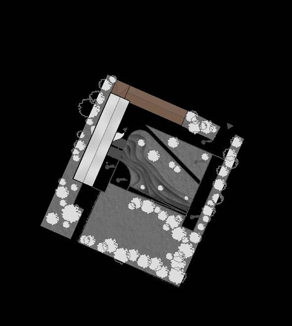
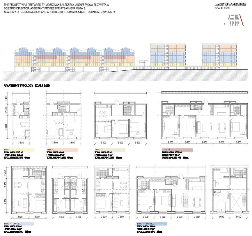
On this territory, we have located several low-rise buildings, which present different types of apartment layouts from studios to flats for families of 5-6 people. In the south of the site, we raised all the buildings above the ground to give more space for courtyards, playgrounds and greenery. Along the railroad, we arranged the buildings in such a way that the blind part of the facade was turned towards the railroad, and the balconies were turned towards the green courtyards. In order to create good noise isolation, we have provided parking under the park that runs along the entire complex located to the west and also a large number of trees to absorb polluted air. One of the main solutions in general is a pedestrian bridge connecting the nearest areas and our quarter, since before that people did not have the opportunity to get to neighboring areas directly because of the highway and railway. Now this area is finally connected to the rest of the neighborhood and people have easy access to everything through to the designed ramp.


Here on the west part of the site we have located numerous premium class apartments as you can see on the plans. There are 7 free standing buildings with the duplex apartments inside which have their own entrannce, paking in front of the house and also inside. In addition to all of this, each owner has his own small garden in front of the complex and the attic. These houses are located close to the railroad tracks, but by raising the skyline higher then usual and crating a park on the side of blank facades facing the railway tracks, we have created an absolutely comfortable living environment for a person - with a minimum of noise and pollution.


TWO LIGHTS

The new project directory as concerned to the course was to build a chain of chapels analogous to the historic ones, but with a purpose to mystrify the beauty of light, with references mainly given to James Turell, a prominent name in the architectures of light.


In 1604 the architect Giuseppe Bernascone , known as “il Mancino”, was summoned to design the various chapels and the scenographic route along the slopes of the mountain: he was the true artistic director of the construction of the entire devotional complex. In this way, in 1604, the Fabbrica del Ss. Rosario was started under the auspices of Cardinal Federigo Borromeo and his delegate for the sacred mountain, the archpriest Alessandro Mazenta .
The greatest fervor of activity, during the seventeenth century, was obviously recorded around the chapels of the Sacro Monte. Here the artistic quality of Giuseppe Bernascone , known as “il Mancino” is appreciated first of all in his ability to represent the prayer of the Rosary “in the form of a monument”, harmoniously merging architectural structures and the landscape. This “scenographic” attitude of his - which also earned him his involvement in the construction site of the Sacro Monte di Locarno– is revealed in the double attention to how the spectator should perceive from a distance the winding of the chapels and triumphal arches along the layout of the wide cobbled street, and how the pilgrim should enjoy, from some chapels, the panorama towards the plain and the Varese lake. It is no coincidence that there are some chapels, around which runs a portico which invites the visitor to admire the surrounding landscape.


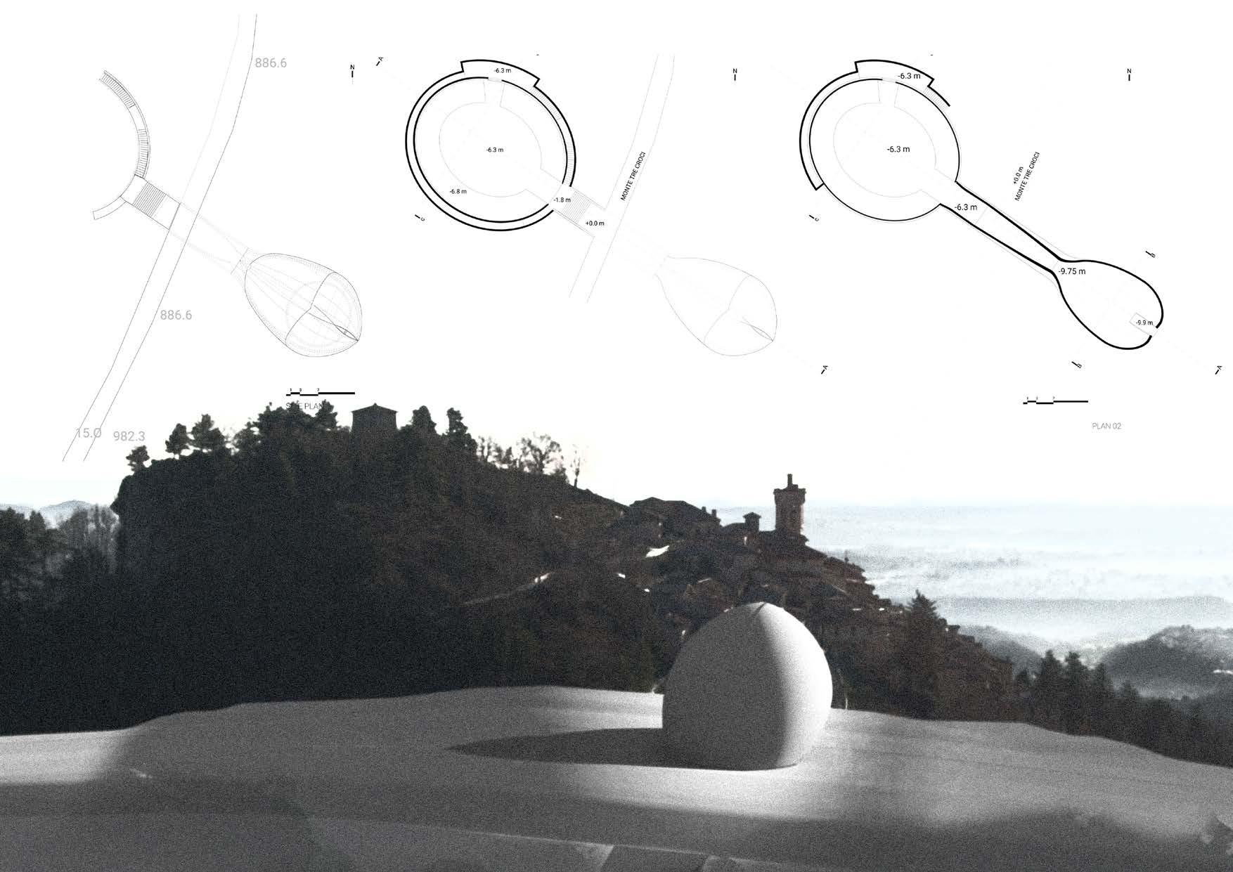
Domed chamber underground, adorned with the lumia exhibtion that projects the universe-like lightings underground is then leads to the vestibule through a tunnel where the beauty of natural light will come about in Cross-shaped.
The philosophy behind the design was to represent light at its most potentiality both artificially and naturally. To achieve it the building is submerged on the slope of the hill. One part of the build is built underground while the other come out to the levitating view looking down to the valley through a tunnel built across under the hiking path. Representing organic nature and the pure geometry, one absorb the similarity of flower petals and the other formed to be a dome.

Also, the presence onf “hiddeness”, promotes the human curiosity and when it was led to the underground, instead of the visible part of the structure, shakes up the excitement and offers interesting experience of travel.
The monumental status was given to the last leg of the buiding with is shaping acquiring the flower petals. Not only representing the nature, but also diffusing the natural light in to a symbolical cross-manner illumination.
ISOMETRIC SECTIONS
THEORY AND HISTORY OF REPRESENTATIONAL METHODS
LUMIA
As the visitor arrive at the hidden chamber it is introduced under the dome, a overwhelming installationg of LUMIA, a light installation with colorful array of lights.
The installation of lumia is as simple as it can be done b y spolighting on a crooked thin sheets of film-like materials, that are roating slowing on a turntable. The playful color refelections on the wall of the dome, in the darkness resemble as grand as to the lights of universe.
Lumia is a form of art that uses light; originally associated with music but was later associated with painting. The term was coined by a twentieth-century artist, Thomas Wilfred.[1] In the early twentieth century, artists began to promote colors and light together in their works. Wilfred worked towards establishing lumia as a new form of art, but the medium has yet to achieve popular recognition.


At his project we were given a space inside the church which is not currently active, but which has retained all the elements of the inerior. The aim of the project was to create an exhibition space where could be placed permanent and temporary exhibits. We had at our disposal not only the space on the floor, but also the entire empty volume that the church gives, we decided to use it all


We have created a structure that is attached to the floor of the church without destroying it. The design is a volume of a parallelepiped, where only supporting pillars are placed on the ground floor, then there is a space glazed around the perimeter, which allows you to create an exhibition on all sides of the floor, and all this ends with an open space where visitors can come as close as possible to the walls of the church and examine all interior details at arm’s length.


