PRODUCT CATALOGUE

SYSTEM SOLUTIONS
ENCLOSURES AND COMPONENTS
ROTARY SWITCHES


Customer-specific solutions
Our engineers have the necessary know-how and resources to realize the special requirements of our customers quickly and affordably.

PRODUCT CATALOGUE
SYSTEM SOLUTIONS
ENCLOSURES AND COMPONENTS
ROTARY SWITCHES
Our engineers have the necessary know-how and resources to realize the special requirements of our customers quickly and affordably.
Elma Electronic AG is a global provider of solutions for the construction of enclosure systems. The product range extends from components for 19'' to modular enclosures, control cabinets and complete systems. The flexibility in customer requests as well as the many years of experience in the development and production of components and systems distinguish Elma as a reliable partner. In the areas of design and manufacture of enclosures for electronic applications, Elma is a leader and innovator, and well known and valued by customer for VME / VME64x, VXI, VXS, PXI, cPCI, ATCA applications and products in harsh environments.
With its headquarters in Switzerland and partners around the world, Elma is able to respond quickly to customer requirements with high-quality solutions. Elma has a broad customer base in a wide variety of industries such as telecommunications, industrial automation, railways, medical and defense technology. The products are always characterized by the highest quality, reliability and performance.
The excellent product design supports customers in optimally positioning their own products in their markets and differentiating them visually. This ensures that the customer's high-quality technology can also be used in the appropriate shell and feel. The modular system of the enclosure platforms enables an individual design for each customer-specific solution.
The perfect enclosure for any application.
› Design and feel can be adapted to customer requirements
› Desktop, tower version or wall mounting
› Available with or without EMC protection
› Different IP protections
› Robust versions available
› Enclosures for mobile use
› Suitable for 19'' applications according to IEC60297
19'' standard according to IEC60297, DIN41494 (for the card slot)
Accessible from all sides x
Suitable as a desktop case
Suitable as a slide-in enclosure (19'' subrack) x x
Suitable as a tower variant x
Suitable for wall mounting
Vibration and
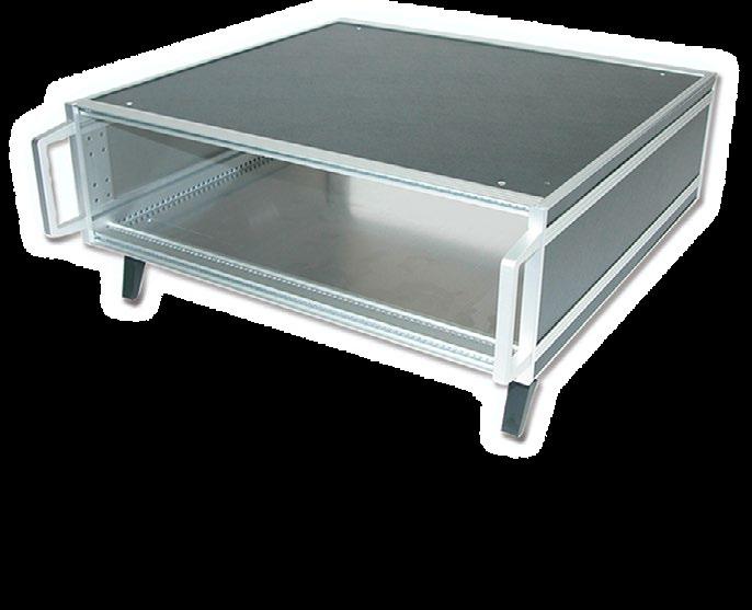
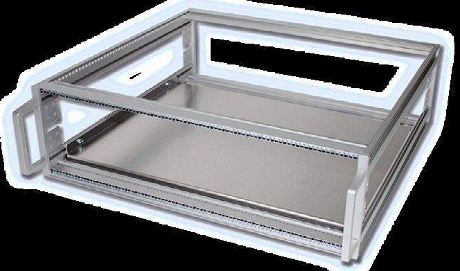
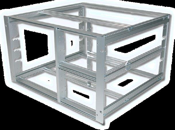
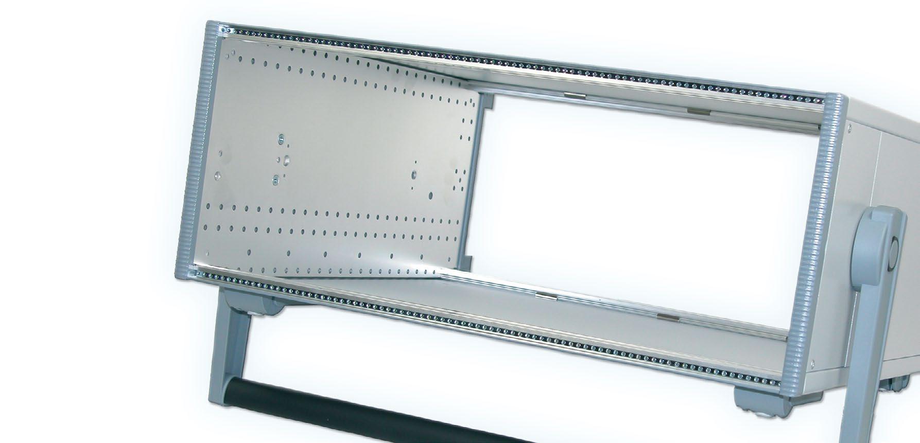
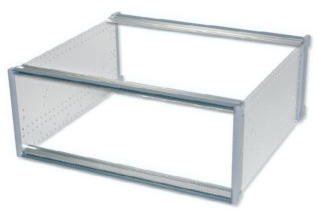
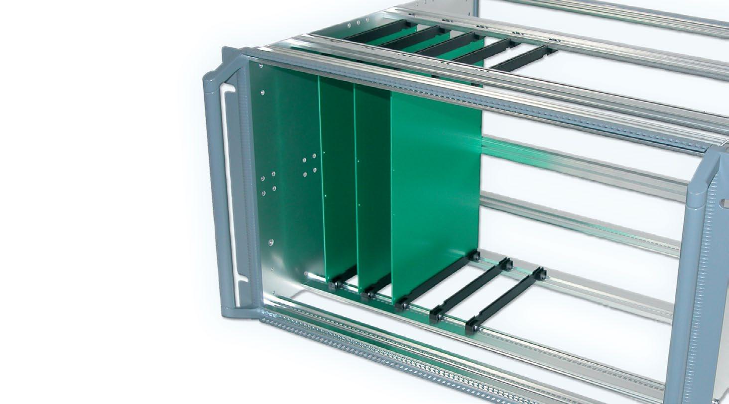
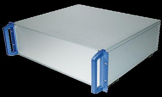
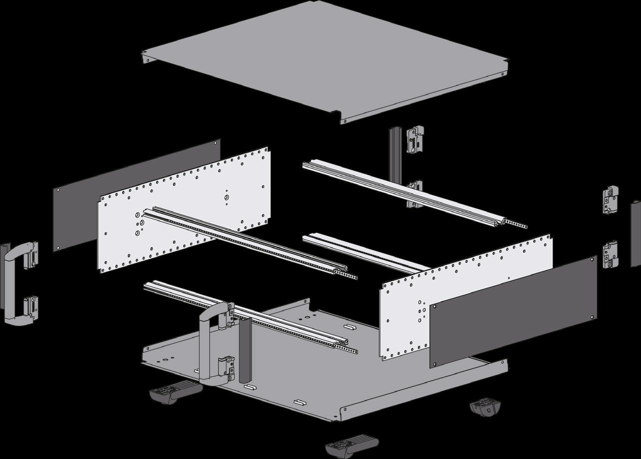
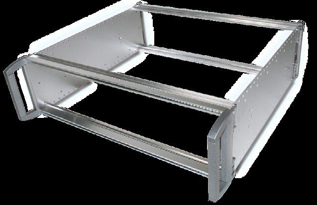
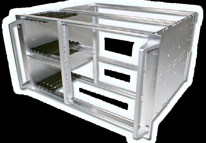
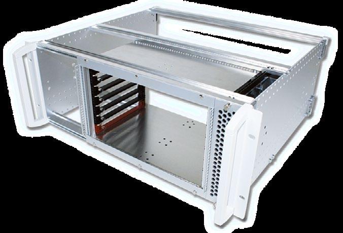
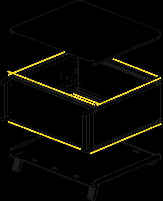
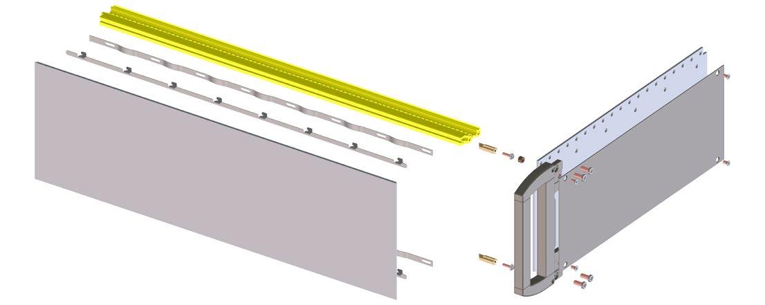
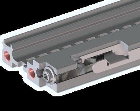
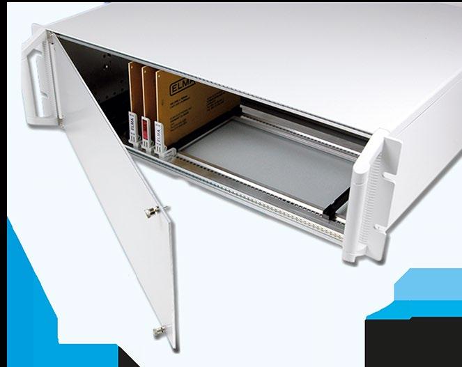
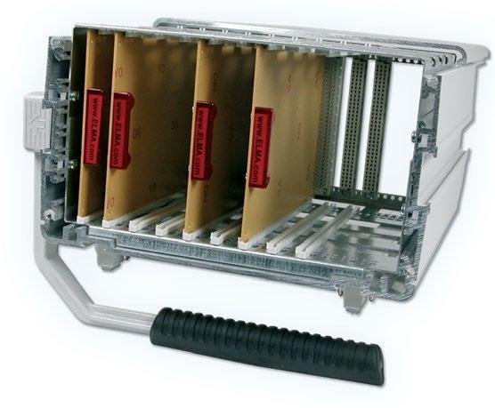
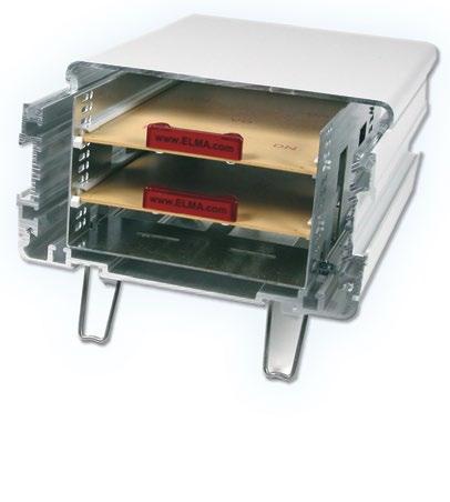
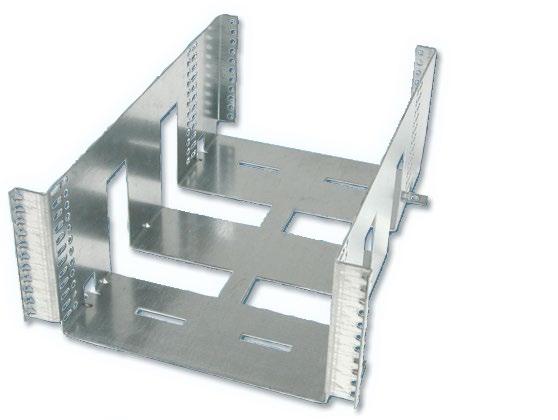
The Unibox 14 be used as a subrack or as a desktop enclosure. The box has dimensions according to IEC60297 and versatile expansion options. The extruded aluminum frame works as a subrack as well as an enclosure (with easy-to-assemble powder coated metal sheets). The card can be installed at the front or rear.
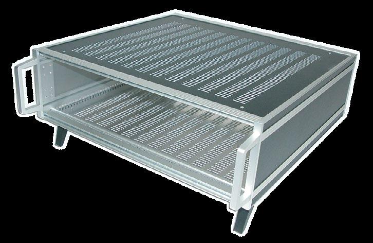
› Usable as subrack or desktop enclosure
› Dimensions according to IEC60297
› Different adaptation options
› Extruded aluminum frame can be used as a subrack or enclosure
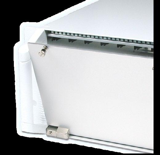
› Subracks can also be installed in cabinets with a cover panel
› Card installation from the front or rear
› When using telescopic or guide rails, only the width 81 HP can be used
› For installing plug-in modules according to DIN41494 or IEC 60297
› Recessed mounting with a pitch of 7.5 mm is possible
› With cover plates suitable for use in vibration applications
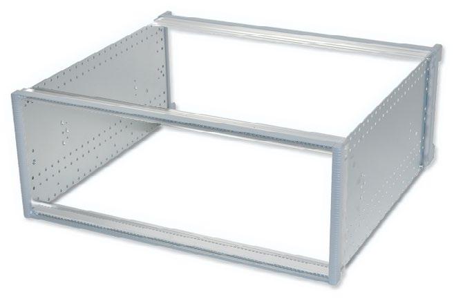
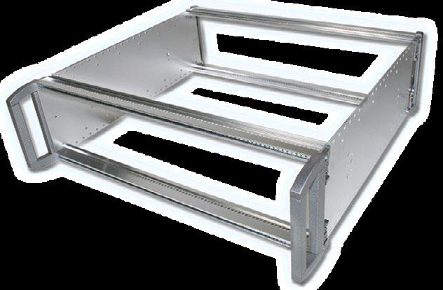
■ Subracks as desktop or 19'' version
■ Cover plates perforated or solid
■ Can be used without cover plates
POSSIBLE CUSTOMIZATIONS
■ Width: 42, 63 or 84 HP
■ Height: 2, 3, 4, 6 or 7 U
■ Depth: 232.6 to 532.6 mm
TYPICAL APPLICATIONS
■ Laboratory equipment
■ Test and measurements device
■ Configurations with card slots
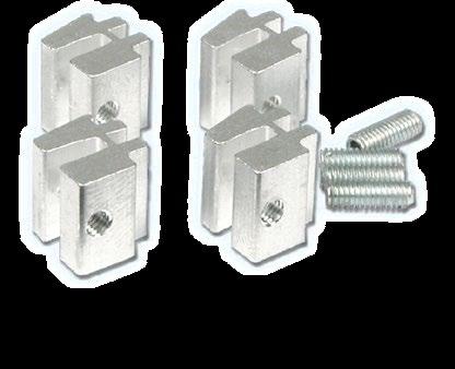
SETS
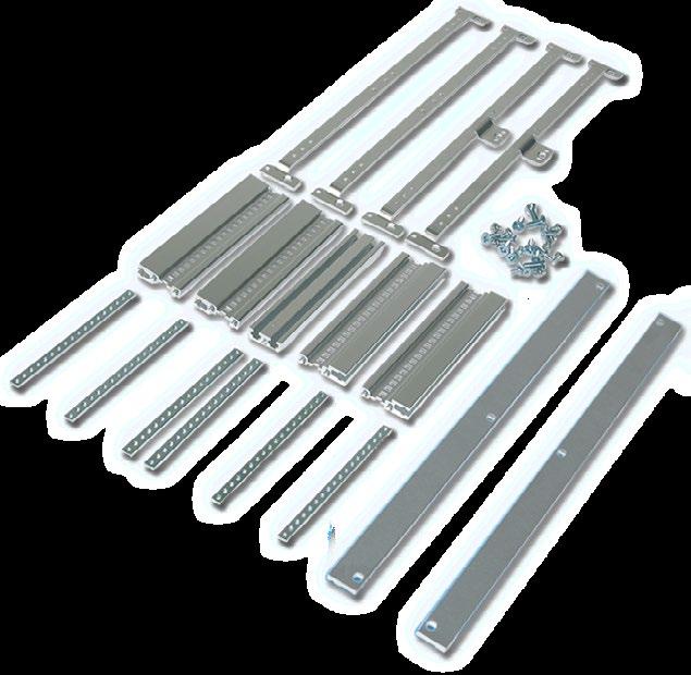
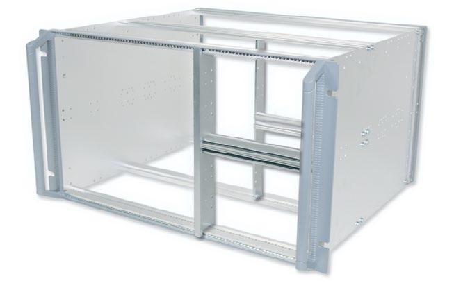
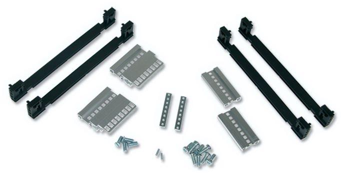
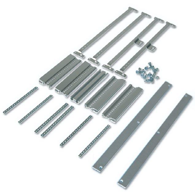
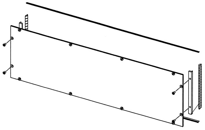
UNIBOX 14 FRAME SET
Scope of delivery:
■ 2 height extrusions front and rear
■ 4 front and rear extrusions
■ 4 depth extrusions
■ 2 handles 9 mm
■ 1 label strip
■ 1 set assembly material
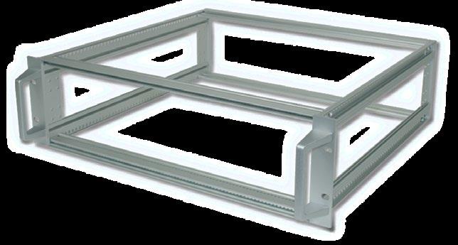
■ Tapped strips, front / rear panel and cover panels have to be ordered separately
Frame without 19'' height extrusions, with handles:
6
Frame with 19'' height extrusions, with handles:
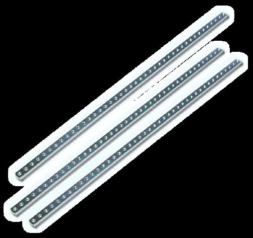
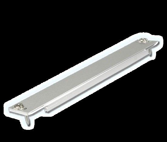
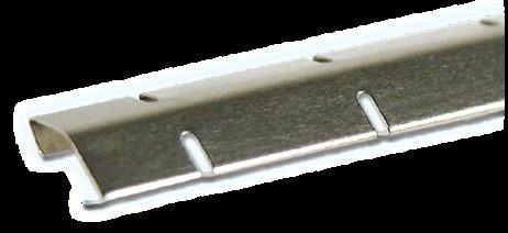
Tapped strips:
■ Steel, zinc-plated
■ Suitable for frames Unibox 14
■ Scope of delivery: 1 tapped strip
SETS
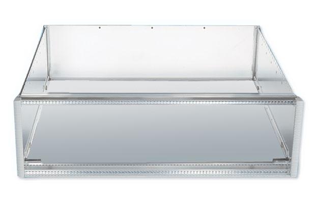
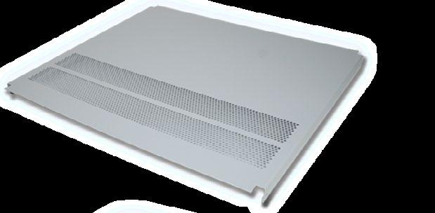
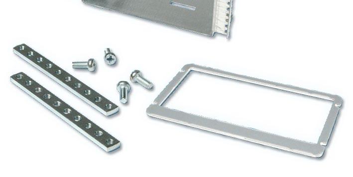
UNIBOX 14 COVER PANEL SET
Scope of delivery:
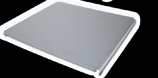
■ 1 top cover panel, solid, RAL7035 fine structure silk gloss
■ 1 bottom cover panel with feet, solid, RAL7035 fine structure silk gloss
■ 2 side panels, solid, RAL7035 fine structure silk gloss
■ 1 set trim strips, RAL7035 fine structure silk gloss
■ 1 set rubber bands
■ 1 set assembly material
2 U 42 HP 140Z422-10 140Z423-10 - -
63 HP 140Z322-10 140Z323-10 140Z325-10 -
84 HP 140Z122-10 140Z123-10 140Z125-10 -
3 U 42 HP 140Z432-10 140Z433-10 140Z435-10
63 HP 140Z332-10 140Z333-10 140Z335-10 -
84 HP 140Z132-10 140Z133-10 140Z135-10 140Z137-10
4 U 42 HP 140Z442-10 140Z443-10 140Z445-10 -
63 HP 140Z342-10 140Z343-10 140Z345-10 -
84 HP 140Z142-10 140Z143-10 140Z145-10 140Z147-10
6 U 42 HP 140Z462-10 140Z463-10 140Z465-10 -
63 HP 140Z362-10 140Z363-10 140Z365-10 -
84 HP 140Z162-10 140Z163-10 140Z165-10 140Z167-10
7 U 84 HP - - 140Z175-10 140Z177-10
3. HEIGHT
/
Scope of delivery:
■ 4 front / rear extrusions
■ 4 tapped strips M2.5
■ Assembly material: 1 set of Phillips screw M4 x 10 (63-109)
Scope of delivery:
■ 4 depth extrusions
Scope of delivery:
■ 2 height extrusions (2 sets have to be ordered separately for front and rear)
Scope of delivery:
■ 1 handle (2 handles per enclosure and 2 screws per handle have to be ordered separately)
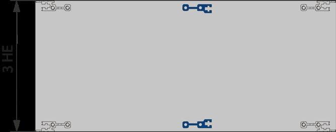
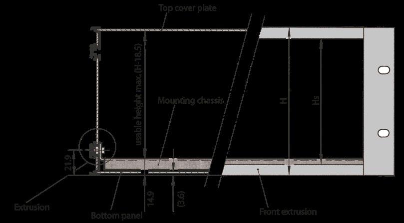
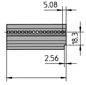
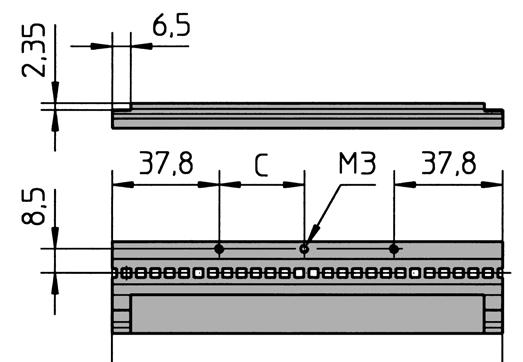
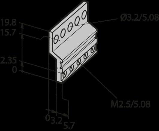
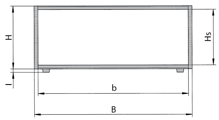
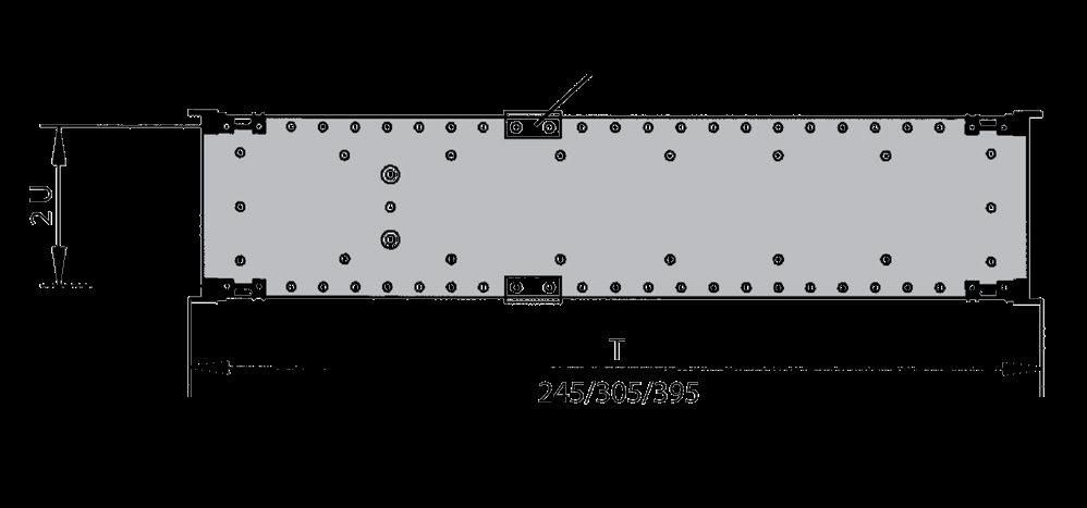
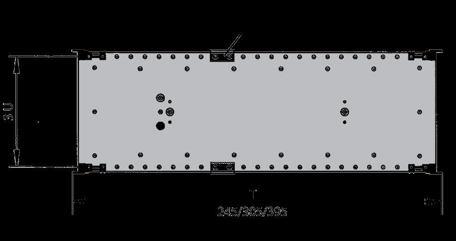
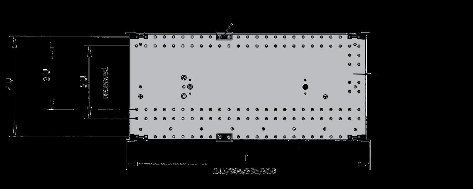
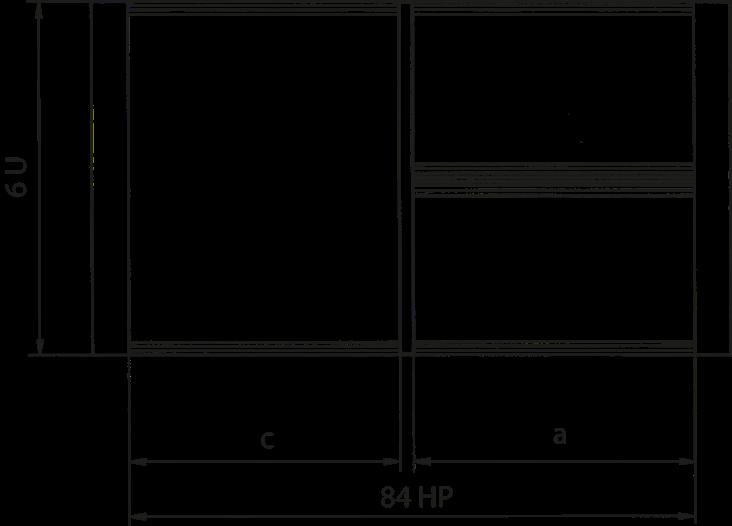
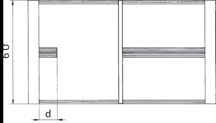
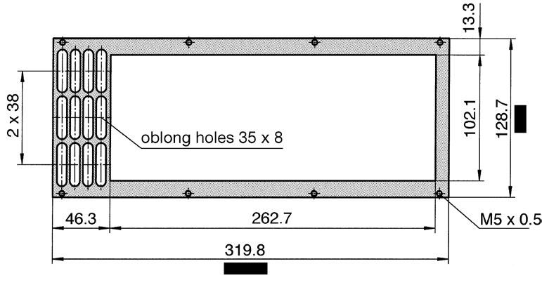
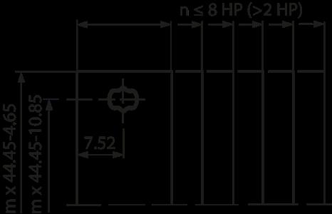
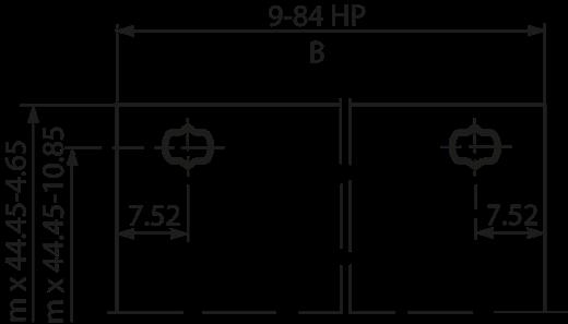
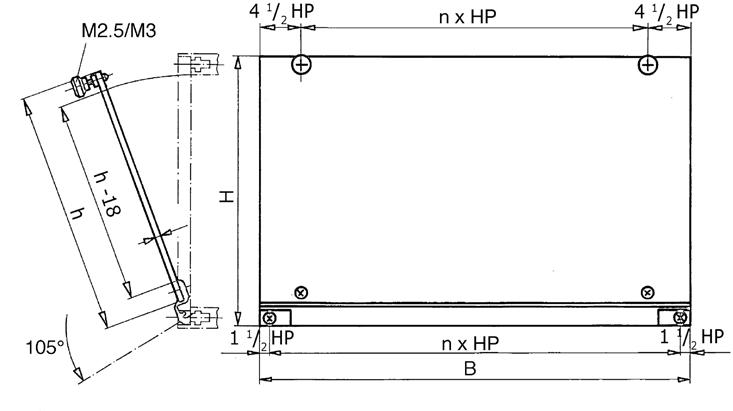
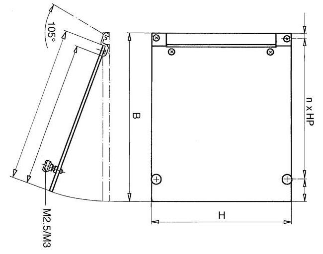
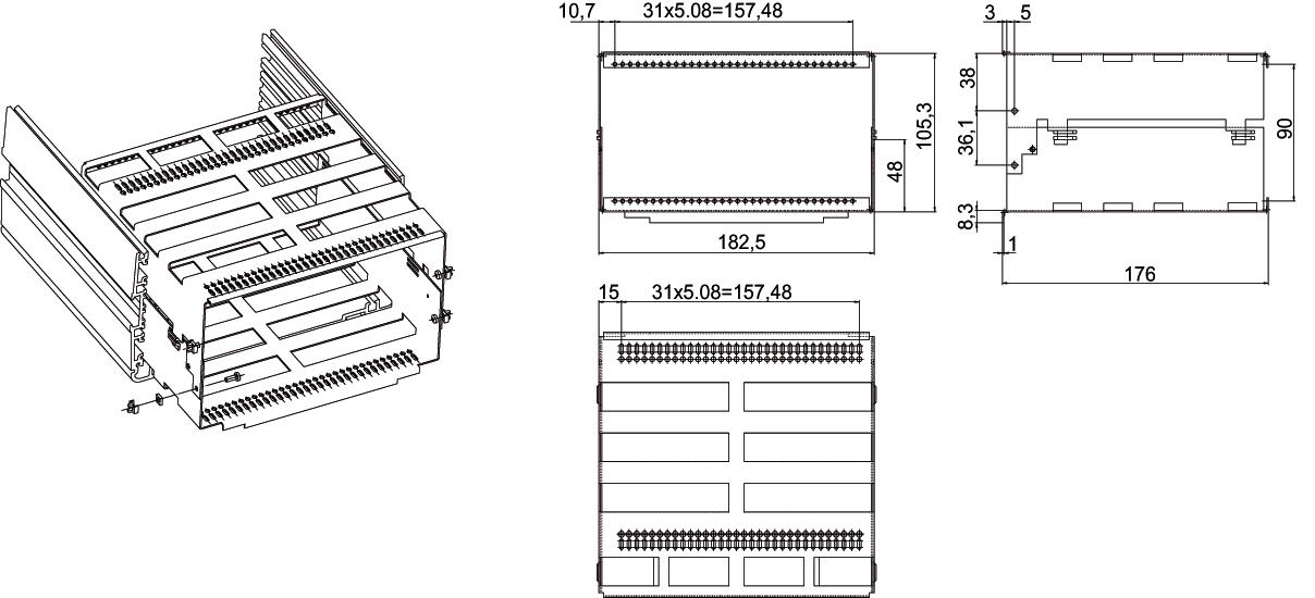
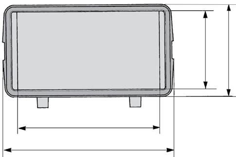
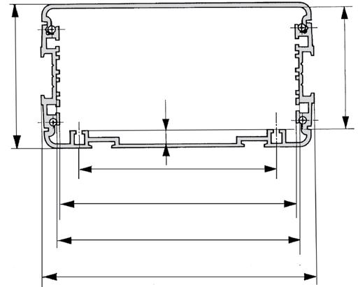
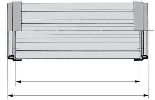
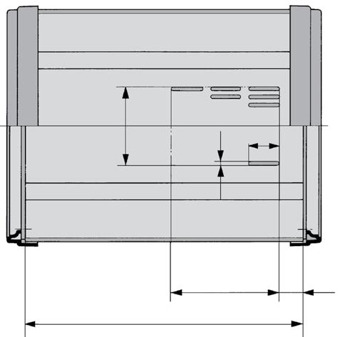
DIMENSION DRAWINGS FOR SUBRACK WITHOUT 19'' HEIGHT EXTRUSIONS
Front view
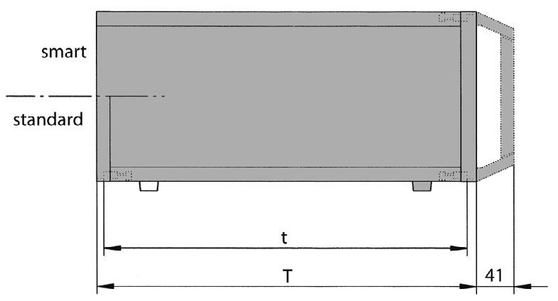
Side view
View from above
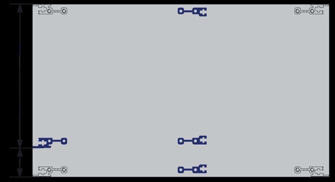
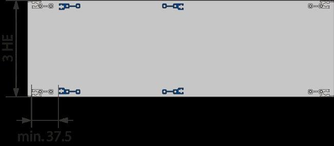
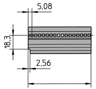
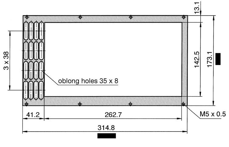
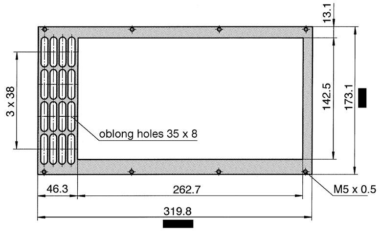
DIMENSION DRAWINGS FOR SUBRACK WITH 19'' HEIGHT EXTRUSIONS
Front view
Frontansicht
Side view
View from above
Width, height and depth for dimension drawings with and without 19'' height extrusions:
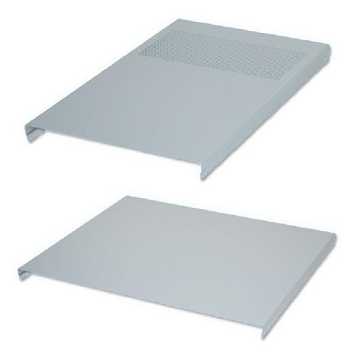
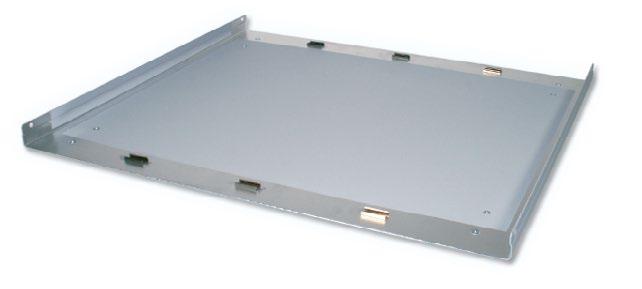
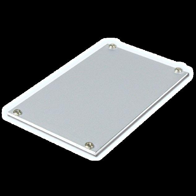
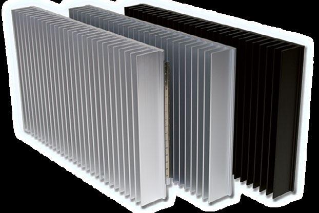
■ One sided powder coated sheet aluminum 1.5 mm
■ Perforated available for better ventilation
Scope of delivery:
■ 1 top cover panel
powder coated, RAL7035
powder coated, RAL7035
Solid, powder coated, RAL7035
Perforated, powder coated, RAL7035
powder coated, RAL7035
powder coated, RAL7035
Solid, powder coated, RAL7035, cranked 84 HP -
Perforated, powder coated, RAL7035, cranked -
Assembly material:
■ For mounting 1 top and bottom cover onto the frame
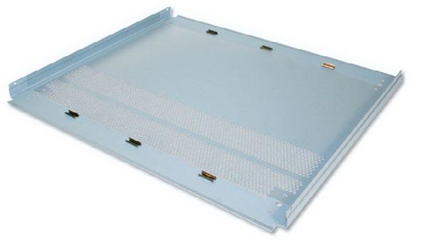
■ One sided film powder coated sheet aluminum 1.5 mm
■ Perforated available for better ventilation
■ With attached feet
Scope of delivery:
■ 1 bottom cover panel
Solid, powder coated, RAL7035 42 HP
Perforated, powder coated, RAL7035
Solid, powder coated, RAL7035 63 HP
Perforated, powder coated, RAL7035
Solid, powder coated, RAL7035 84 HP
Perforated, powder coated, RAL7035
Solid, powder coated, RAL7035, cranked 84 HP -
Perforated, powder coated, RAL7035, cranked -
Assembly material:
■ For mounting top and bottom cover onto the frame
Scope of delivery:
■ 1 side panel
■ Order 2 times for complete enclosure (left and right side)
powder coated, RAL7035
powder coated, RAL7035
powder coated, RAL7035
powder coated, RAL7035
powder coated, RAL7035
powder coated, RAL7035
Perforated, powder coated, RAL7035
Scope of delivery:
■ 4 trim strips
ASSEMBLY MATERIAL
1 set rubber gasket (set of 8 pieces) 292.6 mm 63-097
1 set rubber gasket (set of 8 pieces) 412.6 mm 63-099
1 set rubber gasket (set of 8 pieces) 532.6 mm 63-141
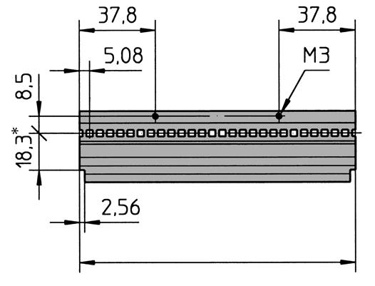
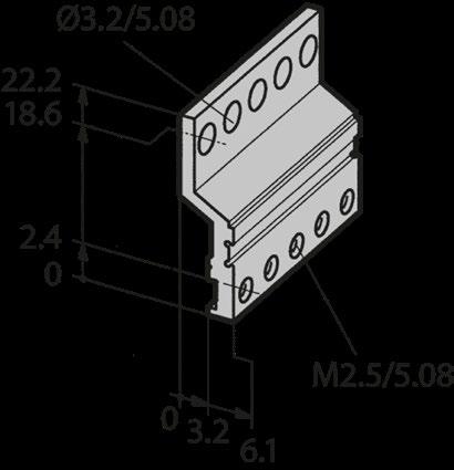
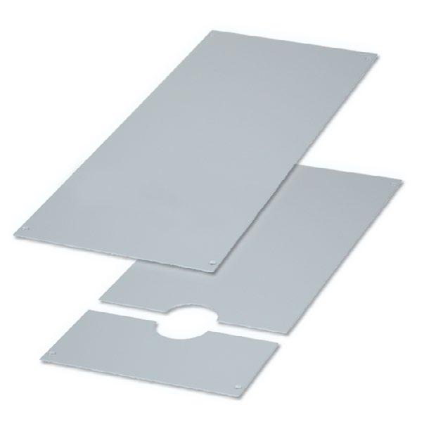
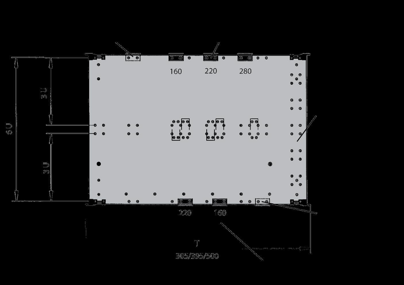
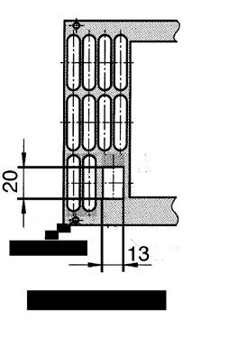
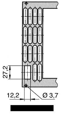
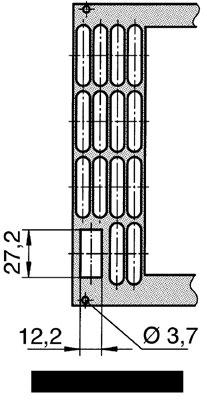
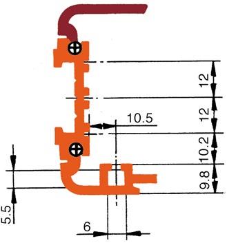
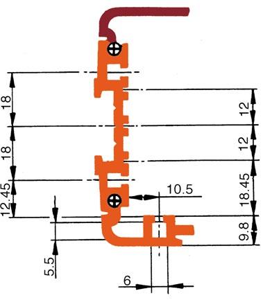
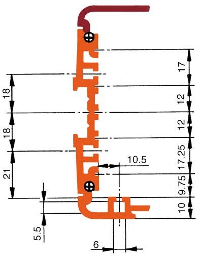
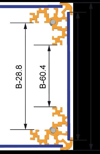
DIMENSION DRAWINGS
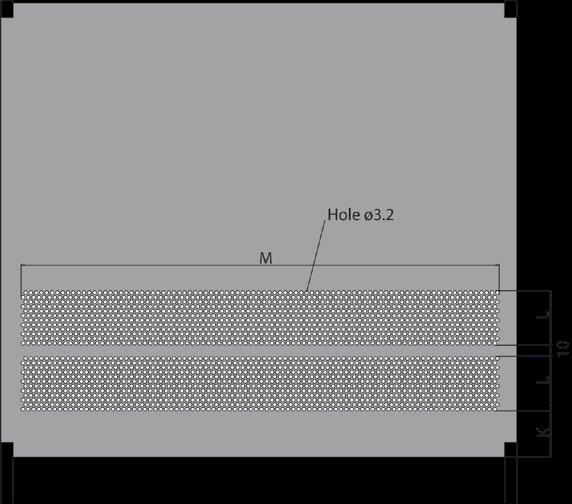
COVER PANEL FORMED FOR ACCOMODATION OF BACKPLANE
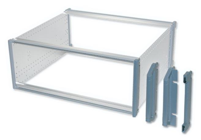
Adaptation kits are used to subdivide the basic frame both in depth and height. Tapped strips have to be ordered separately.
Information for adaptation kits a - e: 14-xxx- x for mounting:
0 = standard extrusion, 66-144 / 66-124
6 = backplane mounting 66-193 (isolated)
Range of application:
■ Single Eurocards | depth 160 to 400 mm
■ Connector to IEC60603-2 / DIN41617 / MIL-C-21097
■ Backplanes, modules, cassettes, plug-in units
■ Crossflow ventilation with 3 U fan module
■ Drive mechanism receptacles 3 1/2'' | 5 1/4''
■ Horizontal mounting of single, double, triple Eurocards
Scope of delivery:
■ 2 internal extrusion
■ 1 set assembly material
Range of application:
■ Single Eurocards | depth 160 to 400 mm
■ Connector to IEC60603-2
■ Backplanes, modules, cassettes, plug-in units
■ Vertical ventilation with 1 U fan module
■ Crossflow ventilation with 3 U fan module
■ Drive mechanism receptacles 3 1/2'' | 5 1/4''
■ Horizontal mounting of single, double, triple Eurocards
Scope of delivery:
■ 3 internal extrusions
■ 1 front extrusion
■ 2 depth dividers
■ 1 set assembly material
Range of application:
■ Recessed mounting of Eurocards without individual front panels
Scope of delivery:
■ 2 internal extrusions
■ 1 set assembly material (for recessed card mounting 2 sets are necessary)
84 HP
Scope of delivery:
■ 1 tapped strip (steel, zinc-plated)
3 U
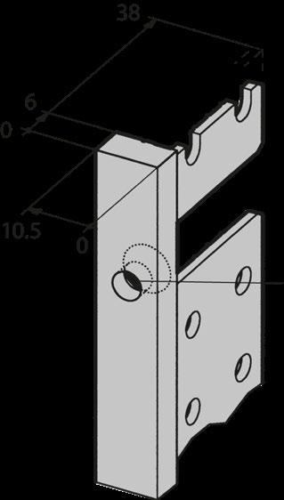
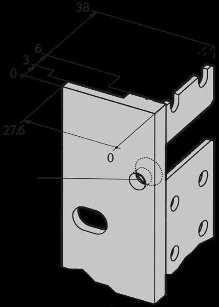
For use with extrusions 66-144, 66-124: For use with extrusion 66-193:
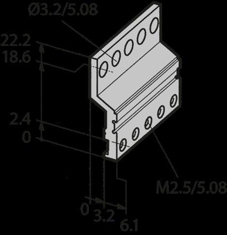
EDGE CONNECTOR EXTRUSION
EDGE CONNECTOR EXTRUSION 66-145-XX | STANDARD EXTRUSION 66-144
Scope of delivery:
■ 1 aluminum extrusion, clear passivated (conductive)
Assembly material:
EDGE CONNECTOR EXTRUSION 66-147-XX | BACKPLANE EXTRUSION 66-193
Scope of delivery:
■ 1 aluminum extrusion, clear passivated (conductive)
Assembly material:
■ Double Eurocards (6 U)
■ Card depth independent
■ Can be installed recessed with additional internal extrusions
■ Top and bottom cover plate when no overall fan front panel (has to be ordered separately)
Scope of delivery:
■ 4 distance plates (2 front / rear)
■ 4 internal extrusions (2 front / rear)
■ 1 center extrusion
■ 6 tapped strips M2.5
■ 1 set assembly material
2
3
Accessories
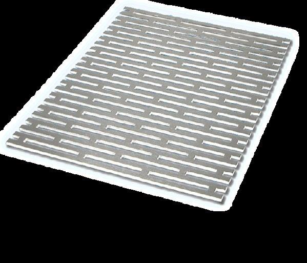
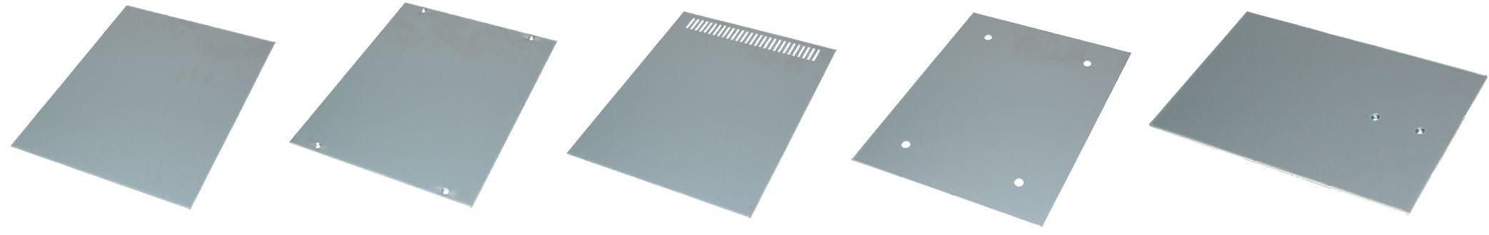
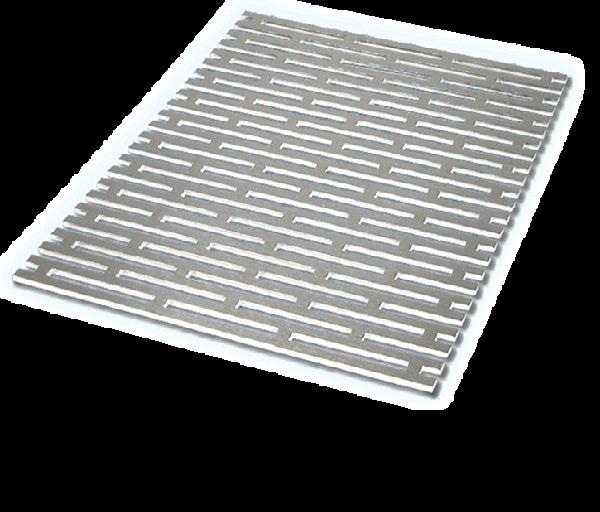
PERFORATED COVER PLATES
■ 1 mm aluminum sheet, perforated
■ Fixing on front and internal extrusions
■ Thread available in front and internal extrusions
■ Provides mechanical protection for the card area
Scope of delivery:
■ 1 perforated cover plate

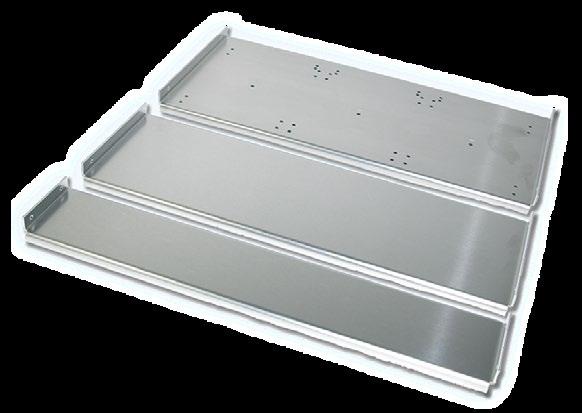
MOUNTING CHASSIS FOR FULL DEPTH
■ For mounting non-standard modules and components
■ Fixed directly to the depth extrusion
■ Aluminum 2 mm, raw
Scope of delivery:
■ 1 mounting chassis
■ Fastening: Depth < 230 mm with 4 screws | > 230 mm with 6 screws
Scope of delivery assembly material:
■ 4 cross recessed cylinder head screw M4 x 6
■ 4 earthing nut M4
■ 4 retaining ring 2 mm
MOUNTING CHASSIS
■ For mounting non-standard modules and components
■ Fixed directly to the depth extrusion
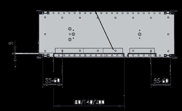
■ Drilling pattern of 200 mm mounting tray allows single, double and triple Euro cards to be attached with standard profiles
Scope of delivery:
■ 1 mounting chassis
Mounting chassis depth 80 mm:
Mounting chassis depth 140 mm:
MOUNTING CHASSIS
MOUNTING CHASSIS
Mounting chassis depth 200 mm:
■ The hole pattern allows single, double and triple Eurocards to be mounted
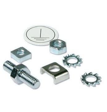
Assembly material:
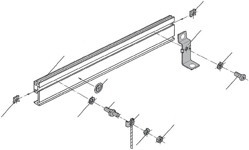
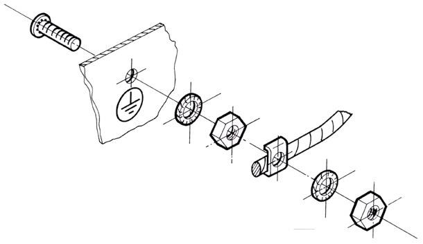
■ Enable subracks and enclosures to be earthed in conformance with VDE / SEV
Scope of delivery:
■ 1 earthing nut M4
■ 1 Threaded bolt M4
■ 1 terminal clamp
■ 2 lock washer
■ 1 nut M4
■ 2 retaining rings 2 mm
■ 1 earthing symbol
Additional set for Unibox 14 with cover plates:
■ 2 earthing nut M4
■ 2 lock washer
■ 4 retaining rings 2 mm
■ 2 earthing clips
■ 2 cross recessed screws M4 x 6
FRONT EXTRUSIONS
FRONT EXTRUSION 66-111 | IEC
Scope of delivery:
■ 1 front extrusion without assembly material
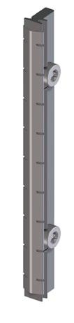
HEIGHT EXTRUSIONS
HEIGHT EXTRUSIONS 66-173
■ Slim version with / without fixing hole for handle
Scope of delivery:
■ 1 height extrusions without assembly material
Montageseite Kartenführung
HEIGHT EXTRUSIONS
HEIGHT EXTRUSIONS 66-179
■ With / without fixing hole for handle
■ 19'' height extrusions for 84 HP
Scope of delivery:
■ 1 height extrusions without assembly material
2
3
4
5
6
7
8
DEPTH EXTRUSIONS
Scope of delivery depth extrusion 66-177:
■ 1 depth extrusion without assembly material
352.6 13.55 66-177-23 412.6 16.24 66-177-24
532.6 20.96 66-177-26
Scope of delivery depth extrusion 66-176:
■ 1 depth extrusion without assembly material
INTERNAL EXTRUSIONS
STANDARD INTERNAL EXTRUSION 66-144
■ Standard extrusion for mounting supplementary edge connector extrusions in subracks and enclosures
Scope of delivery:
■ 1 internal extrusion without assembly material
66-193 FOR INSULATED BACKPLANE
■ For mounting backplanes in subracks
■ Rabbet to accept 1.8 x 5 mm tapped strips
■ To use with insulation strips 66-901
Scope of delivery:
■ 1 internal extrusion without assembly material
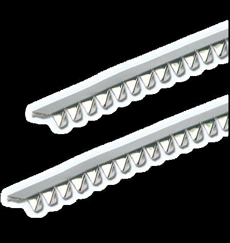
INSULATING STRIPS 66-901
■ Plastic gray
■ In use with extrusions 66-112, 66-192, 66-193, 66-288
429.8 16.92 66-901-23
Mounting with insulation strips:
66-194 FOR CONDUCTIVE BACKPLANE MOUNTING
■ For mounting backplanes without an insulating strip
■ Rabbet to accept 1.8 x 5 mm tapped strips
Scope of delivery:
■ 1 internal extrusion without assembly material
■ Supplementary edge connector extrusion for IEC60603-2 connectors
■ Matches to 66-144, 66-133 and 66-124
Scope of delivery edge connector extrusion 66-145:
■ 1 edge connector extrusion without assembly material
320 12.6 66-145-65
411.5 16.2 66-145-22
426.7 16.8 66-145-52
53.14 66-145-19
Scope of delivery edge connector extrusion 66-147:
■ 1 edge connector extrusion without assembly material
3.59 66-147-41 28 142.2 5.6 66-147-42
42 213.4 8.4 66-147-63
63 320 12.6 66-147-65
81 411.5 16.2 66-147-22
84 426.7 16.8 66-147-52
1350 53.14 66-147-19 Length
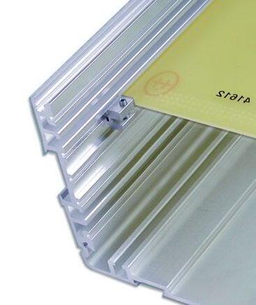
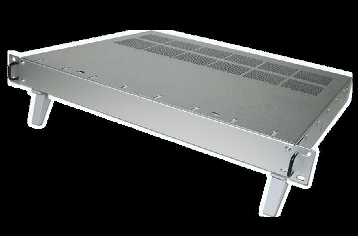
STYLEBOX 15 STANDARD
• Extrusions and inner sides aluminium
• Aluminium covers
• EMC-shielding basic as standard
• Identical front and rear for insertion of boards, modules, etc.
• Dimensions to IEC 60297
• Top design
• Simple assembly
• Lightweight and sturdy
• Conductive contact surfaces
• Visible surfaces are powder-coated
• Colour: Cover light grey (NCS 2502-B), frame and feet dark grey (NCS 5010-R90B)
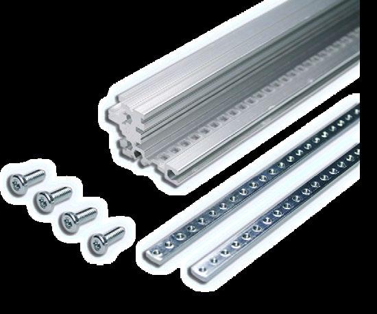
• For Stylebox 15 Standard
• Extrusions: Aluminium, conductive
• Scope of delivery:
• 4 front/rear extrusions
• 4 tapped strips M 2.5
• 1 set of 16 screws (Cross recessed M4x10)
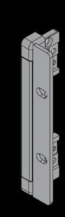
HEIGHT BEZEL
• For Stylebox 15 Standard
• Die cast parts: Aluminium, powder coated
• Contact area conductive
• Scope of delivery:
• 2 height bezels
• 2 sets have to be ordered (for front and rear side)
DEPTH
• For Stylebox 15 Standard
• 2.0 mm Aluminium, clear passivated
• Scope of delivery:
• 1 internal side panel
• 2 pieces have to be ordered (for left and right side)
• For Stylebox 15 Standard
• 1.0 mm Aluminium, powder coated, contact area conductive
• Scope of delivery:
• 1 top cover panel
BOTTOM COVER
• For Stylebox 15 Standard
Top Cover
• 1.0 mm Aluminium, powder coated, contact area conductive
• Scope of delivery:
• 1 bottom cover with mounted feet
Bottom Cover
• For Stylebox 15 Standard
• Outer side, visible surface
• 1.0 mm Aluminium, powder coated
• Scope of delivery:
• 2 side panels
• Assembly material (8 cross recessed countersunk screw M3x6, 2 hock-and-loop fastener) Side Panel
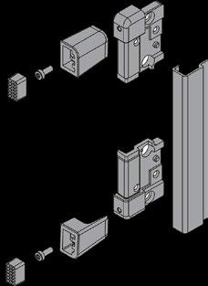
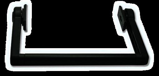
PORTABLE DESKTOP HANDLE
• For Stylebox 15 Standard
• Scope of delivery:
• 2 adapters
• 2 side parts
• 1 handle extrusion, softfeel
• Assembly material

2 U
4 U
3 U 6 U
ADAPTATION KITS
• Adaptation kits are used to subdivide the Stylebox 15 both in its depths and heights
• The adaptation kits for the flush or recessmounted circuit boards or cassettes include the necessary internal extrusions and assembly material
• Scope of delivery is show in blue in the following illustrations
Note:
Information for Adaptation Kits a - e:
15-xxx- x for mounting:
6 = 66-193, for insulated backplane mounting
7 = 66-194, for conductive backplane mounting
ADAPTATION KIT A
• Range of Application:
• Single eurocard depth 160 – 280 mm
• Motherboard
• Modules, cassettes, plug-in units
• Set for horizontal mounting of single, double triple eurocards, depth 160 – 280mm
• Crossflow ventilation with 3 U fan module
• Drive mechanism receptacles 31/2"/51/4"
Adaptation Kit a
• Scope of delivery:
3
• 2 internal extrusions
• 2 insulating strips (-6 only)
• 2 tapped strips M2.5
• 1 set assembly material
Other widths available on request.
• For use with extrusions for backplanes 66-193
• Scope of delivery:
• 1 aluminium extrusion, clear passivated (conductive)
Connector Extrusion
Front Sub Division Vertical for 6 U System or 6 U Assembly
• Allows both single and double eurocards to be mounted together in a 6 U Stylebox 15
• Scope of delivery:
• 1 divider extrusion front
• 1 divider extrusion rear
• 2 front extrusions
• 2 internal extrusions
• 1 assembly material
• Tapped strips for front extrusion see below
Front Sub Division Vertical for 6 U Assembly
Tapped Strips for Front Extrusion
CARD MOUNTING KIT FOR DOUBLE EUROCARDS (6 U)
• For double eurocards (6 U)
• Independent of card depth
• The horizontal card mounting kit can be fitted recessed within the Stylebox 15 by using two additional extrusions
• Scope of delivery:
• 4 distance plates (2 front / 2 rear)
• 4 length extrusions (2 front / 2 rear)
• 1 centre extrusion
• 6 tapped strips M2.5
• 1 set assembly material

Horizontal Card Mounting Kit\
* Assembly material for cover plate see
* Other versions available on request.
Mounting Chassis Full Depth of Stylebox 15 Standard
• For mounting non-standard modules and components
• Mounting chassis is fixed directly on the side panels
• Aluminium 2.0 mm, raw
• Scope of delivery:
• 1 mounting chassis
• Assembly material see below
• Mounting chassis depth < 230 mm can be
Mounting Chassis Full Depth of Stylebox 15 Standard
Assembly Material
• For one mounting chassis
• Scope of delivery:
• 4 cross recessed cylinder head screw M4 x 6
• 4 earthing nut M4
Mounting Chassis Small for Mounting of Power Supplies, etc.
Chassis depth 80 mm
A
Chassis depth 140 mm Case
Mounting Chassis for Horizontal Mounting of Eurocards
• Chassis depth 200 mm
• The hole pattern allows single, double and triple eurocards to be mounted
Mounting Set for One Eurocard
• Scope of delivery:
• 2 front extrusions
• 2 internal extrusions
• Card guides (2 - 6 pcs.)
• tapped strips
• Assembly material
• Protects the Stylebox 15 from damage when the case is lifted and set down by using the case handle
• Scope of delivery:
• 2 height bezels rear
• 4 rear feet
• 4 screws M4x10
• 4 plastic inserts
Rear Feet for Stylebox 15 Standard
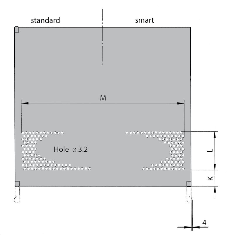
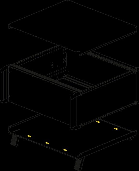
Gaskets for Advanced EMC level (Stylebox 15 Standard)
• Vertical gaskets for cover plates (partial)
• To achive an advanced EMC level with Stylebox 15 Standard
• No additional gaskets for width necessary
• Drawing shows the position of the gaskets
Depth Gaskets for Covers
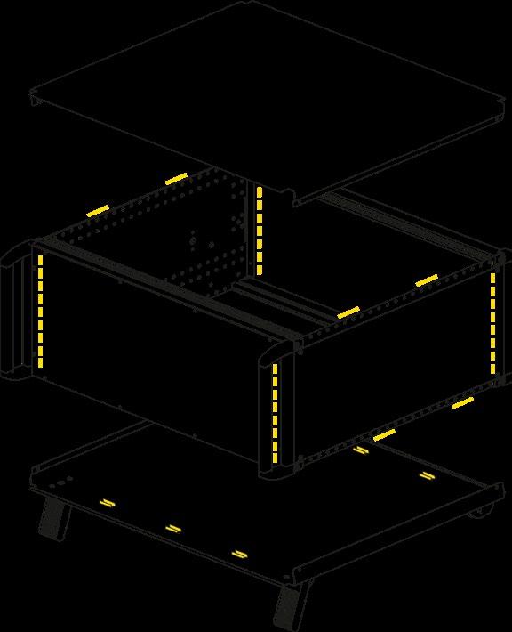
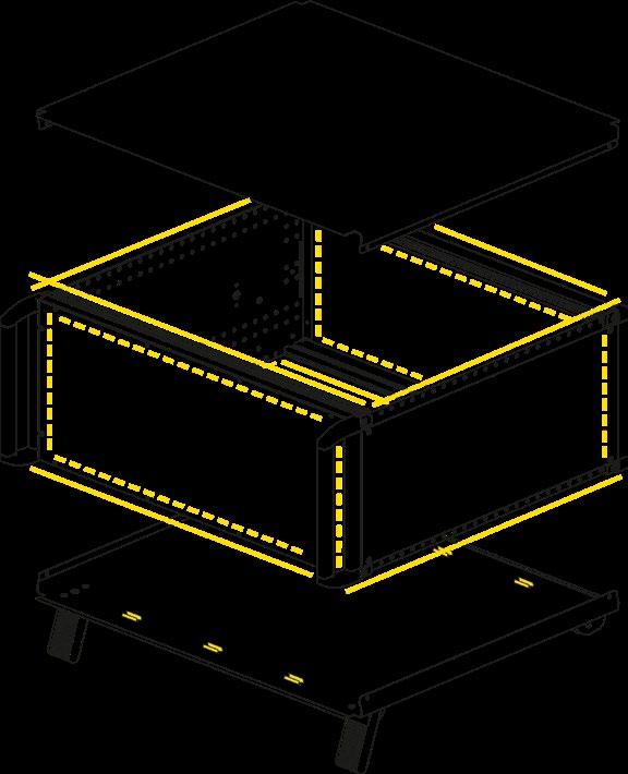
FOR SUPERIOR EMC LEVEL (STYLEBOX 15 STANDARD)
Gaskets for Superior EMC level (Stylebox 15 Standard)
• Vertical and horizontal gaskets for cover plates (overall)
• To achive superior EMC level with Stylebox 15 Standard
• Order 1 set each for width and depth
• Drawing shows the position of the gaskets
Width Gaskets for Covers
Depth Gaskets for Covers
EMC Contact Strips (Advanced EMC-level)
• 2 contact strips
• For front panels, fixing on extrusion
• Self-adhesive
• Enables cases to be earthed in conformance with EN / VDE / SEV
• Scope of delivery:
• 1 press-in threaded bolt M4
• 2 serrated lock washers
• 2 hexagonal nuts M4
• 1 terminal clamp
• 1 earthing symbol

Stylebox 15 e-motion is a portable desktop case according to the 19'' standards. It is a platform that was built according to the IEC60297 standard. The scalable EMC protection, color and design variants make it the first choice for high-end electronics. The top design, the variety of sizes and variants as well as the wide range of accessories create ideal conditions for a variety of applications such as controls, measuring devices or computer systems.
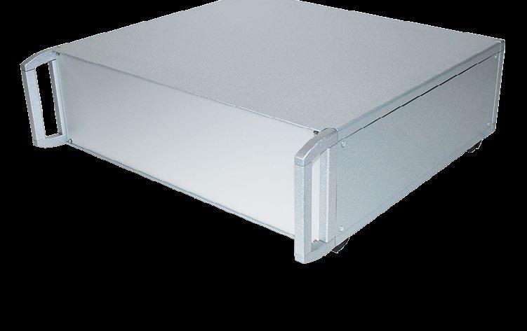
› Case system: 4 longitudinal aluminum profiles and 2 side walls as a supporting frame sheet steel cladding
› The front of the case can be fitted as required with cover brackets, front handles or 19'' fixing bracketsthis permits subsequent conversion from a desktop case to a 19'' module unit and vice-versa
› Mounting dimensions according to IEC60297
› Numerous accessories
› Internal mounting chassis
› Horizontal and vertical insertion of Eurocard PCBs
› Elegant design
■ Cover plates bolted to the side
■ Front of the enclosure can be equipped with cover brackets, front handles or 19'' fixing brackets
■ Colorless passivated inside of the cladding
■ Longitudinal profiles colorless passivated (enable a large area contacting for optimal EMC protection)
■ Top and bottom plates on the contact surfaces color-free
■ Optional EMC seals for increased EMC protection
■ Optional folding feet for use in installation angles
■ Different sizes
■ Colors: White, silver (other colors on request)
■ Customizations
■ Standard or customized front panels
■ Optional scalable EMC shielding
■ Rear I/Os possible
■ 19'' subrack Systems (e.g. for IEC or IEEE controller cards)
■ Measurement and test instruments
■ Laboratory or field instruments
■ Medical equipment
■ Height: 2 to 7 U
■ Width: 42 | 63 | 84 HP
■ Depth: 245, 305, 395 or 500 mm
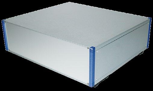
COLORS
■ White
■ Silver
■ Other colors on request
SPECIAL FEATURES
■ Increased EMC shielding on request
■ Rear inputs and outputs
CUSTOMIZATIONS
■ Standardized or customized front panels
■ Customized front and rear panels on request
EMC VARIANTS
EMC CONSTRUCTION AND CONFIGURATION
Basic level
Size: 4 U x 84 HP x 395 mm Standard front panel (cover panels perforated and unperforated)
Advanced level
Size: 4 U x 84 HP x 395 mm EMC front panels and gasket kit (cover panels perforated and unperforated)
Superior level
Size: 4 U x 84 HP x 395 mm EMC front panels and gasket kit (cover panels perforated and unperforated)
Electromagnetic comptability is the ability of a system to operate in the intended environment without causing or suffering unacceptable degradation of performance due to unintentinal electromagnetic radiation or response. The EMC characterstics of a system therefore consist of an appropriate immunity from interference (noise immunity) and a limited emission of interference (noise emission).
Elma’s EMC concept describes three levels of electromagnetic shielding performance (performance level). The attenuation levels will simplify the selection of sub racks for the user. Test setup: The first measurement E1 is without the enclosure. The next measurement E2 is made with the transmitting antenna installed inside the enclosure. The difference between the received signal without and with the enclosure represents the shielding effectiveness in dB.
1
2
3
The standard configuration will provide you with a basic (Stylebox 15 Standard or e-motion) or an advanced EMC level (Stylebox 15 smart). If you require an advanced or superior EMC level for your system, you need to order additional EMC parts.
TYPICAL ATTENUATION
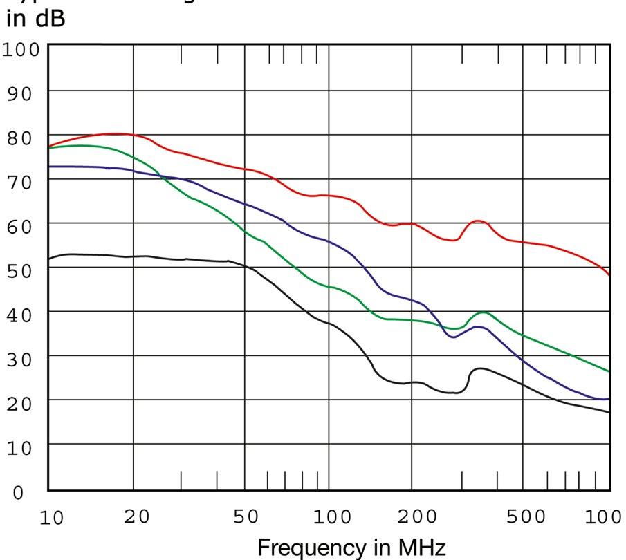
Basic EMC level Case size 4 U-x-42 HP-x-245 mm (9.64'') with standard front panels (cover panels perforated and unperforated)
Basic EMC level Case size 4 U-x-84 HP-x-395 mm (15.55'') with standard front panels (cover panels perforated and unperforated)
Advanced EMC level Case size 4 U-x-84 HP-x-395 mm (15.55'') with EMC front panels and gasket set for advanced EMC level (cover panels perforated and unperforated)
Superior EMC level Case size 4 U-x-84 HP-x-395 mm (15.55'') with EMC front panels and gasket set for superior EMC level (cover panels perforated and unperforated)
STYLEBOX 15 E-MOTION COMPILATION
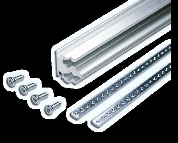
■ Aluminum profile, electrically conductive
Scope of delivery:
■ 4 front / rear extrusions
■ 4 tapped strips M 2.5
■ 1 set of 16 screws torx T20 (M4 x 10)
■ 19'' version do not allow additional cover brackets
■ Profiles and die-cast parts: Aluminum, powder coated or wet painted, contact area conductive
Scope of delivery:
■ 1 brackets
■ 4 pieces have to be ordered (for front and rear side)
Support feet and according bezels
Description Color 2 U 3 U 4 U 6 U Rear Feet Black 15S090 15S090 15S090 15S090 Plus cover panel White 66-686-060-70 66-686-105-70 66-686-149-70 66-686-238-70 Silver 66-686-060-80 66-686-105-80 66-686-149-80 66-686-238-80
■ Internal side panel 2 mm aluminum, clear passivated
Sope of delivery:
■ 1 internal side panel
■ 2 pieces have to be ordered (for left and right side)
2
3
4
4
6
7
■ Symmetrical construction: Perforation can be used at front or rear
■ 0.75 mm sheet steel powder coated or wet painted, contact area conductive
Scope of delivery:
■ 1 top cover
Perforated, silver 15B210-81 15B212-81 15B213-81 15B214-81
■ Symmetrical construction: Perforation at front or rear
■ 0.75 mm sheet steel powder coated or wet painted, contact area conductive
Scope of delivery:
■ 1 bottom cover with mounted feet
silver
silver
white
Perforated, white 15B310-71 15B312-71 15B313-71 15B314-71
Perforated, silver 15B310-81 15B312-81 15B313-81 15B314-81
■ With and without tilt feet
■ Glass-fiber reinforced plastic, UL94 V-0
■ Including screws 3.5 x 8 size T10
■ Up to 30 kg carring capacity per set
Scope of delivery:
■ 2 + 2 case feet, incl. rubber inserts NBR
■ 8 countersunk PT-screws torx T10 (3.5 x 8)
Case feet
2 x a + 2 x b Light grey (RAL 7035) 63K524
Case feet 2 x a + 2 x b Black (RAL 9005) 63K526
Case feet 2 x a + 2 x b Dark grey (special) 63K525
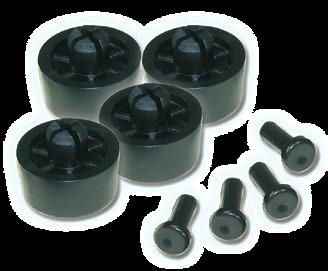
■ Plastic and aluminum (mounted direct onto side panel)
Scope of delivery:
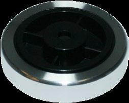
■ 4 round feet, Ø 40 mm
■ 4 round head screws with integrated washer torx T10 (M3 x 8)
Scope of delivery:
■ 2 adapters
■ 2 side parts, black
■ 1 handle extrusion, soft feel
■ Assembly material, torx
2 HP 15S050 15S051 15S052
3 and 4 HP 15S053 15S054 15S055
■ Side panel 2 mm aluminum, clear passivated
Scope of delivery:
■ 1 inner side wall
■ 2 pieces have to be ordered (for left and right side)

Solid, white for portable desktop 15B658-70 15B662-70 15B667-70
silver for
Solid, silver 15B603-80 15B608-80 15B613-80 15B623-80 15B628-80
Solid, white for portable desktop 15B659-70 15B663-70 15B668-70
Solid, silver for portable desktop 15B659-80 15B663-80 15B668-80
Solid, white 500 19.68 - 15B609-70 15B614-70 15B624-70 15B629-70
Solid, silver - 15B609-80 15B614-80 15B624-80 15B629-80
Solid, white for portable desktop - 15B664-70 15B669-70
Solid, silver for portable desktop
15B664-80 15B669-80
Longitudinal sections for placement in 15 mm grid
Longitudinal sections for placement in 15 mm grid
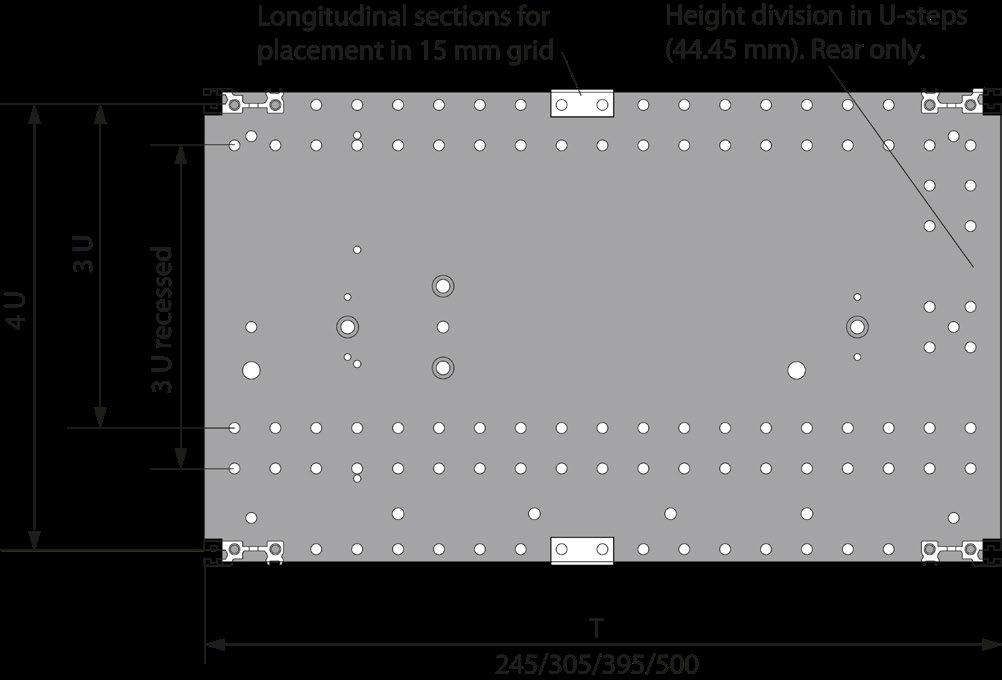
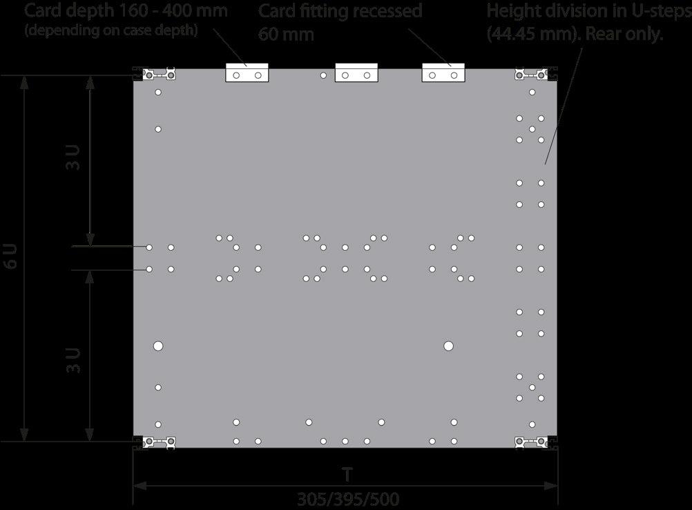
Adaptation kits are used to subdivide both depth and height. The adaptation kits for the flush or recess mounted circuit boards or cassettes include the necessary internal extrusions and assembly materials.
Information for adaptation kits a - f: 15-xxx- x for mounting:
6 = Extrusion 66-193, for insulated backplane mounting
7 = Extrusion 66-194, for conductive backplane mounting
Range of application:
■ Single Eurocard with depth 160 to 280 mm
■ Backplanes
■ Modules, cassettes, plug-in units
■ Set for horizontal mounting of single, double triple Eurocard, with depth 160 to 280 mm
■ Crossflow ventilation with 3 U fan module
■ Drive mechanism receptacles 3 1/2'' | 5 1/4''
Scope of delivery:
■ 2 internal extrusions
■ 2 insulating strips (only 15K0xx - 6)
■ 2 tapped strips M2.5
■ 1 set assembly material, torx
Range of application:
■ Recessed mounting of single Eurocards, with depth 160 to 220 mm
■ Without individual front panels
■ Backplanes
Scope of delivery:
■ 4 internal extrusions
■ 2 insulating strips (only 15K0xx - 6)
■ 2 tapped strips M2.5
■ 1 set assembly material, torx
Recessed mounting of single Eurocards without front panels
Reduction kit 1/3 U + 2/3 U for 60 mm recessed mounting
Range of application:
■ Recessed mounting of single Eurocards, with depth 160 to 220 mm
■ With or without individual front panels
■ Max. fan height 26 mm
■ Backplanes
■ Modules, cassettes, plug-in units
■ Drive mechanism receptacles 5 1/4''
Scope of delivery:
■ 2 internal extrusions
■ 2 longitudinal extrusions 66-111 (IEC) or 66-677 (IEEE)
■ 2 insulating strips (only 15K0xx - 6)
■ 1 auxiliary cover top
■ 1 auxiliary cover bottom
■ 4 tapped strips M2.5
■ 1 set assembly material, torx
Scope of delivery:
■ 1 fan plate
■ 8 milled edge screws torx T10 (M3 x 5)
Range of application:
■ Double Eurocards with depth 160 to 280 mm
■ Backplanes
■ Modules, cassettes, plug-in units
■ Drive mechanism receptacles 3 1/2'' | 5 1/4''
Scope of delivery:
■ 2 internal extrusions
■ 1 centre extrusion
■ 4 insulating strips
■ 4 tapped strips M2.5
■ 2 set assembly material, torx
kit reduction, perforated*, without fan panel
Adaptation kit
perforated*, with fan panel
Range of application:
■ Recessed mounting of double Eurocards, with depth 160 to 220 mm
■ Without individual front panels
■ Backplanes
Scope of delivery:
■ 4 internal extrusions
■ 1 centre extrusion
■ 4 insulating strips
■ 4 tapped strips
■ 2 set assembly material, torx
Reduction kit 1/3 U + 2/3 U for 60 mm recessed mounting
Range of application:
■ Recessed mounting of double eurocards with depth 160 to 220 mm
■ With or without individual front panels
■ Max. fan height 26 mm
■ Backplanes
■ Modules, cassettes, plug-in units
■ Drive mechanism receptacles 5 1/4''
Scope of delivery:
■ 2 internal extrusions
■ 2 longitudinal extrusions 66-111 (IEC) or 66-677 (IEEE)
■ 2 insulating strips (only -6 and IEEE, if -6 and IEC 4 strips needed)
■ 1 centre extrusion (only IEC)
■ 1 auxiliary cover top
■ 1 auxiliary cover bottom
■ 4 tapped strips M2.5 (6 pieces for IEC)
■ 1 set assembly material, torx
Scope of delivery:
■ 1 fan plate
■ 8 milled edge screws torx T10
Scope of delivery:
■ 1 aluminum extrusion, clear passivated (conductive)
Scope of delivery:
■ 1 divider extrusion front
■ 1 divider extrusion rear
■ 2 longitudinal extrusions
■ 2 internal extrusions
■ Assembly material:
16 cylinderhead screws torx T20 (M4 x 10)
4 cylinderhead screws torx T10 (M3 x 12)
■ For dividing 6 U systems
■ Direct mounting onto the height extrusion and side panel
■ For width of 4 and 8 HP
■ Other sizes on request
Scope of delivery:
■ 2 divider extrusions front
■ 2 divider extrusions rear
■ 2 tapped strips M2.5
■ 8 cylinder head screws M4 x 10
■ 4 slotted countersunk screws M4 x 10
■ 2 set screws for fixing of tapped strips M2.5 x 8
■ 2 card guides 160 mm (4 pieces for 8 HP version)
■ For double Eurocards (6 U)
■ The horizontal card mounting kit can be fitted recessed by using two additional extrusions
■ If no overall fan plates is used, the top and bottom cover plate has to be ordered separately
■ Fan front panels, card guides and front panels see below
Scope delivery:
■ 4 distance plates (2 front | 2 rear)
■ 4 longitudinal extrusions (2 front | 2 rear)
■ 1 centre extrusion
■ 6 tapped strips M2.5
■ 1 set assembly material
■ Top and bottom cover plate has to be ordered separately
■ For horizontal mounting of double Eurocards
■ Aluminum 2.5 mm, clear anodised (non-conductive)
■ With cutout for power switch
Scope of delivery:
■ 1 perforated fan front panel
■ Set of 10 screws
■ With threaded or press-fit bush
■ 8 screws are necessary per front panel
■ For 160 mm card depth
■ For backplane mounting with insulating strips
■ Fan slot on the right side of the horizontal installation kit
Lieferumfang:
■ 1 connector plate
■ 2 + 14 card guides
■ 2 cover plates
■ 2 endplates
■ 2 longitudinal extrusions
■ 2 internal extrusions
■ 4 insulating strips
■ 1 fan plate without fan
■ 4 tapped strips M2.5
■ 1 set of assembly material
■ 1 set of EMC gaskets
■ 14 ESD clips and 14 ESD springs (IEEE version only)

EMC FRONT SUB DIVISION
EMC FRONT SUB DIVISION HORIZONTAL IEC FOR CARD GUIDES
■ For sub division of front and rear
■ Card guides can be applied on one side
■ EMC level: Superior
■ Only one special extrusion needed
■ Easy and quick assembly
■ Cost effective solution
■ Delivered as a kit
■ Usable width: 84 HP
■ Other sizes on request
Scope of delivery:
■ 1 front double extrusion IEC-special, clear passivated
■ 2 tapped strips M2.5
■ 4 cylinder head screws torx T0 (M4 x 10)
■ For sub division of front and rear
■ No possibility of mounting card guides
■ EMC level: Superior
■ Only one special extrusion needed
■ Easy and quick assembly
■ Cost effective solution
■ Delivered as a kit
■ Usable width: 84 HP
■ Other sizes on request
Scope of delivery:
■ 1 front double extrusion IEC-special, clear passivated
■ 2 tapped strips M2.5
■ 4 torx cylinder head screws M4 x 10 (T20)
■ EMC level: Superior
■ Only one special extrusion needed
■ Card guides can be applied
■ Easy and quick assembly
■ Cost effective solution
■ Usable width: 84 HP
■ Other sizes on request
Scope of delivery:
■ 1 front double extrusion IEEE-special clear passivated
■ 2 tapped strips M2.5
■ 4 cylinder head screws torx T20 (M4 x 10)
■ Stainless steel
■ Snapped-in on the extrusion
Scope of delivery:
■ 2 HF spring 84 HP
■ BeCu galvanized
■ For front panels, fixing on extrusion
■ Self-adhesive
Scope of delivery:
■ 2 EMC contact strips
■ For mounting non-standard modules and components
■ Mounting chassis is fixed directly on the side panels
■ Aluminum 2 mm, raw
Scope of delivery:
■ 1 mounting chassis (depth: < 230 mm can be mounted with 4 screws | > 230 mm with 6 screws)
Scope of delivery for assembly material:
■ 4 cylinder head screw torx T20 (M4 x 6)
■ 4 earthing nut M4
CHASSIS DEPTH 80 MM
Scope of delivery for assembly material:
■ 4 cylinder head screw torx T20 (M4 x 6)
■ 4 earthing nut M4
CHASSIS DEPTH 140 MM
Scope of delivery for assembly material:
■ 4 cylinder head screw torx T20 (M4 x 6)
■ 4 earthing nut M4
CHASSIS DEPTH 200 MM
■ The hole pattern allows single, double and triple Eurocards to be mounted
ASSEMBLY MATERIAL
Scope of delivery:
■ 4 cylinder head screw torx T20 (M4 x 6)
■ 4 earthing nut M4
Scope of delivery:
■ 2 front extrusions
■ 2 internal extrusions
■ Card guides (2 to 6 pieces)
■ 2 tapped strips
■ Assembly material
GASKETS FOR ADVANCED EMC LEVEL
■ Vertical gaskets for cover plates (partial)
■ To achieve an advanced EMC level
■ No additional gaskets for width necessary
Depth gaskets for covers:
GASKETS FOR SUPERIOR EMC LEVEL
■ Vertical and horizontal gaskets for cover plates
■ To achieve superior EMC level
■ Order 1 set each for width and depth
Width gaskets for covers:
Depth gaskets for covers:
■ Will be interlocked with front panel
■ For additional increase of EMC to advanced level
■ Aluminium, clear passivated
Scope of delivery:
■ 2 EMC front extrusion
■ 2 EMC springs
■ Assembly material (2 screws torx T8, adhesive foil)
■ For front panels, fixing on extrusion
■ Self-adhesive
Scope of delivery:
■ 2 contact strips
FLAT FRONT PANELS
■ For subracks and enclosures, solid
■ Aluminum 2.5 mm, clear anodised (non-conductive)
■ 1 HP and 2 HP are divider extrusions (not flat panels)
Scope of delivery:
■ 1 flat front panel
Flat front panels for subracks and enclosures, solid:
Coverplates for 1 U fan opening
Front panel screws:
■ Set of 10 screws, M2.5 x 11.3, with screw retainer
EMC FRONT PANELS
EMC FILLER PANELS WITH EMC GASKET
■ High stability (U-profile)
■ Extruded aluminum
■ Pressed-in centring pin and bushes M2.5
■ Front side clear anodised | rear side conductive
Scope of delivery:
■ 1 EMC front panel incl. pressed-in centering pin and bushes M2.5 (pressed-in) EMC
8
9
10 HP
EMC FRONT PANELS
EMC FILLER PANELS WITHOUT EMC GASKET
■ Front panel standard, solid
■ Front clear anodised | rear conductive
■ Basic EMC level
Scope of delivery:
■ 1 front panel incl. press-fit bushes M2.5 (pressed-in) EMC
Front panel screws: ■
■ Aluminum 2.5 mm (conductive)
■ Front panel without visible screws
■ Closes the front and rear side of the chassis with big shielding effect
■ Contact between flat front panel and chassis is made with an EMC gasket
Scope of delivery:
■ 1 EMC design front panel
■ 2 plate slider
■ 2 holder
■ 2 locking device
■ 2 filister head screw M2.5 x 40
Scope of delivery:
■ 1 EMC flat front panel
■ Contact angle, incl. screws
■ EMC gasket for contact angle, front extrusion, front panel
Front panel screws:
■ Front panel width 42 HP = 4 screws
■ Front panel width 63 HP = 6 screws
■ Front panel width 84 HP = 8 screws
■ Front anodised, rear conductive
■ Advanced EMC level
■ Width: 84 HP
Scope of delivery:
■ Perforated flat front panel


Front panel screws:
FAN FRONT PANELS 84 HP FOR VERTICAL VENTILATION
■ Fan front panel: Perforated and designed with optimum air flow rate
■ Available with or without switch cut-out (switch opening 22 x 30.6 mm)
■ Aluminum 2.5 mm, clear anodised (non-conductive)
Scope of delivery:
■ 1 perforated fan front panel


Front panel screws:
■ Set of 10 screws, M2.5 x 11.3
■ With screw retainer
■ Fan front panel ~1 U = 4 screws | 2 U = 6 screws
FAN FRONT PANELS
FAN FRONT PANELS FOR HORIZONTAL VENTILATION
■ Aluminum 2.5 mm, clear anodised (non-conductive)
Scope of delivery:
■ 1 perforated fan front panel
3
6
Front panel screws:
■ Set of 10 screws, M2.5 x 11.3
■ With screw retainer
■
FAN FRONT PANELS FOR DIRECT FAN MOUNTING
■ Aluminum 2.5 mm, clear anodised (non-conductive)
Scope of delivery:
■ 1 perforated fan front panel


Front panel screws:
■ Set of 10 screws, M2.5 x 11.3
■ With screw retainer
Screws torx (M2.5 x 11.3) with plastic screw retainer
Milled edge screws recessed M2.5 x 11.3 with plastic screw retainer
HINGED FRONT PANELS
Assembly material for fan mounting:
■ Hinges are attached to the front extrusions of the subrack or case
■ Aluminum 2.5 mm, clear anodised (non-conductive)
Scope of delivery:
■ 1 Front panel
■ Hinge extrusion
■ Assembly material M2.5, incl. hinges
Dimensions:
nut M4, 0.8D
BOTTOM-HINGED FRONT PANELS
EMC TOP / BOTTOM-HINGED FRONT PANELS
■ Width: 84 HP
■ Optimum protection from electromagnetic interference
■ Aluminum 2.5 mm
■ Front anodised | rear conductive
Scope of delivery:
■ 1 EMC front panel
■ Hinge extrusions
■ Assembly material M2.5, incl. hinges
■ EMC gaskets
SIDE-HINGED FRONT PANELS
■ Aluminum 2.5 mm, clear anodised (non-conductive)
Scope of delivery:
■ 1 front panel
■ Hinge extrusion
■ Assembly material M2.5, incl. hinges
■ For subracks and enclosures
■ Width 42 HP
■ Cooling fins in pitch of 11/2 HP
■ Aluminum anodised or clear passivated
■ EMC version with mounted brackets for slide in of EMC gaskets 81-062-xx
■ Customised versions on request
Scope of delivery:
■ 1 heat sink front panel M2.5 incl. hinges
Assembly Material:
EMC GASKET
Scope of delivery:
■ Stainless steel
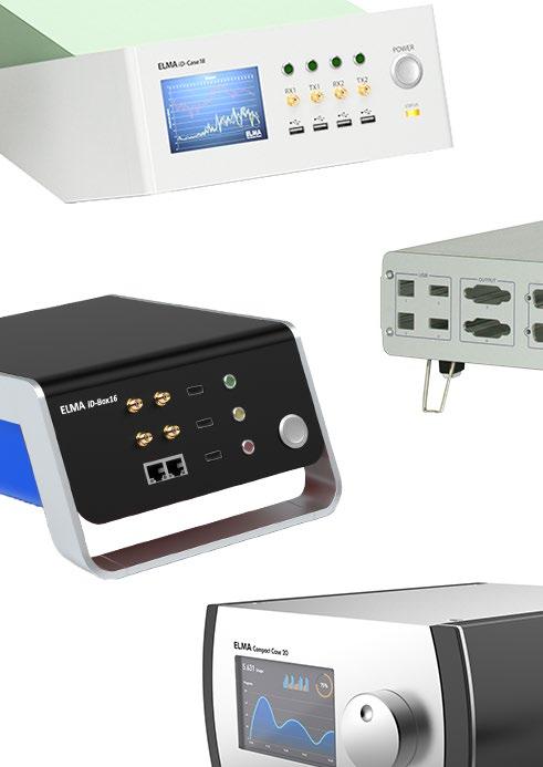
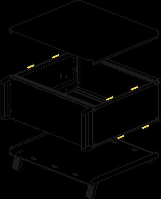
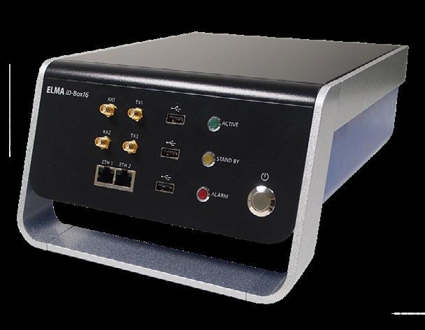
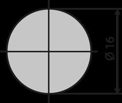
The iD-Box 16 is a versatile housing for high-quality electronic components. It is a standard-independent system, which is not only based on the individual wishes of the end customer, also adapts its size to the requirements as well as the needs of the application.
Assembling this product is easy. In addition, Elma offers you fully integrated system solutions.
■ Standard-independent enclosure system
■ Ergonomic HMI-Interface
■ Selectable dimensions
■ Flexible mounting options
■ High design aestetics
■ EMV level: Basic or Advanced
■ Thermal analysis on request
■ Ingress protection: IP40
■ reddot award 2014 winner
■ Individual colour combination
■ Customer-specific design front and rear panel
■ Customer-specific HMI interface
■ Mounting options of electronics
■ EMC level: Basic or Advanced
Customizable sizes:
■ Size L
■ Size M
■ Size S
■ Size XS
TYPICAL APPLICATIONS
■ Test and measurement technology
■ Sensor technology
■ Medical equipment
■ Testing and calibrating devices
■ Optical and mechanical measuring systems
■ Standard: Blue, green and red
■ Customization on request
■ Selectable for base plate, over, frame, front and rear panel
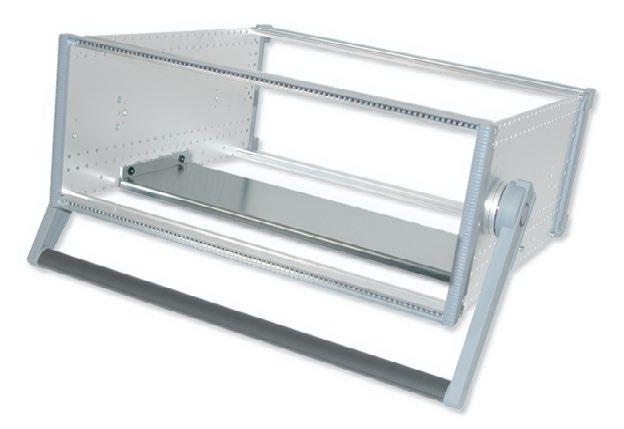
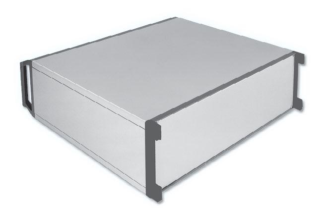
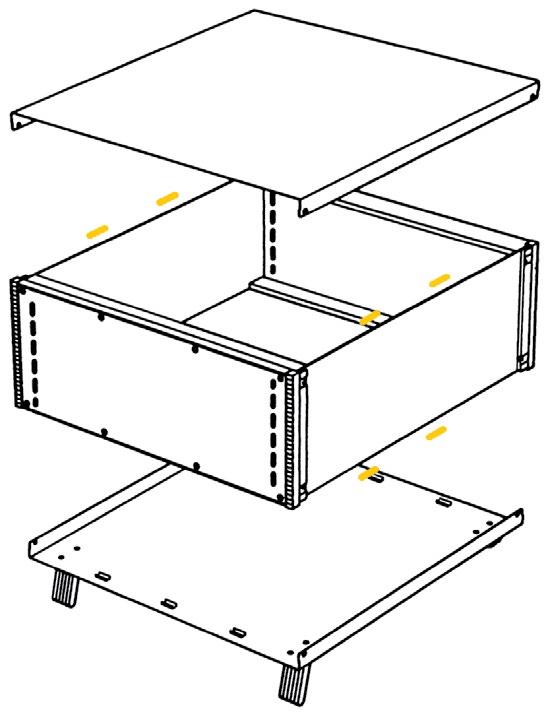
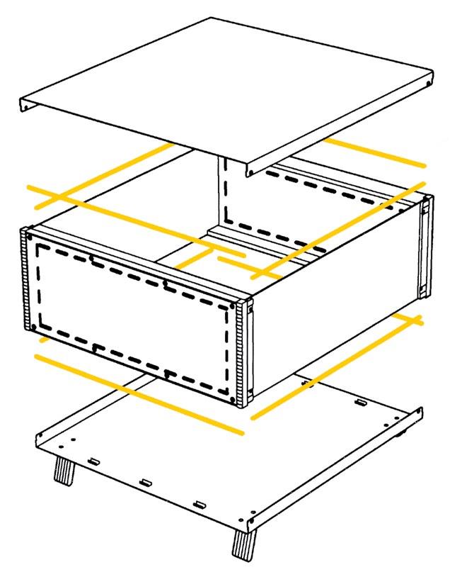
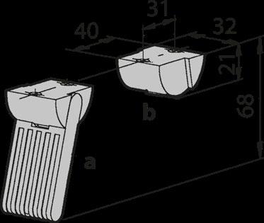
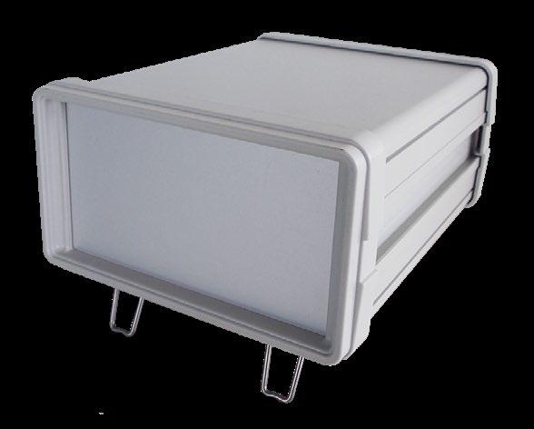
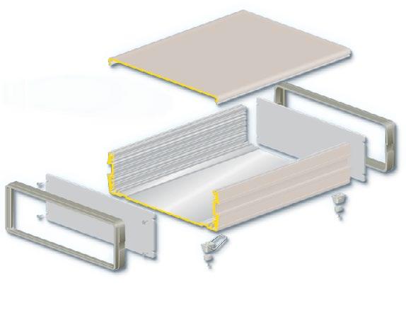
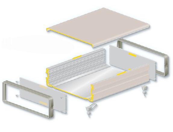
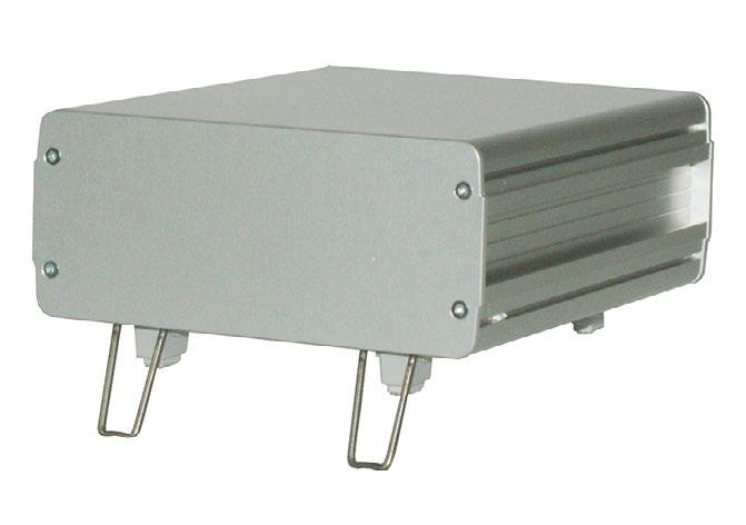
With the iD-Case 18, every technical device stands out from the crowd. Thanks to the easily removable cover, access to the electronics is easy and thus minimizes the assembly effort to a minimum. The four sizes of the case offer a lot of freedom for customer-specific design. With the foldable feet, the front can be positioned vertically or inclined 20° to the installation surface. This means that the device can be operated optimally, both standing and sitting.
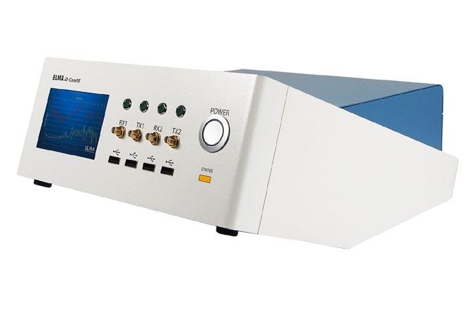
■ Exceptional design and high design aesthetics
■ Ergonomic operation
■ Four standard sizes
■ Different color combinations
■ Easily accessible inside the enclosure
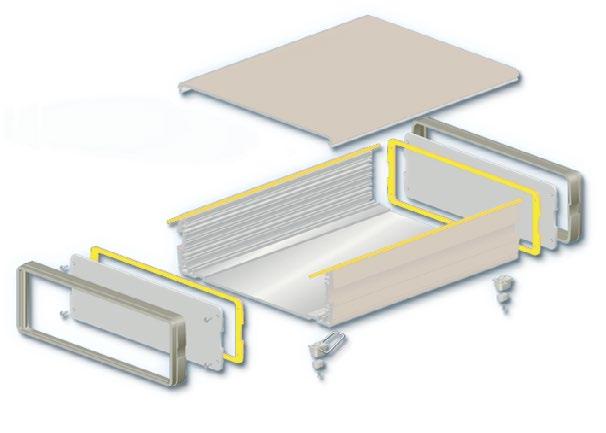
■ EMC protection: Basic or Advanced
■ Different colors
■ Enhanced EMC protection
TYPICAL APPLICATIONS
■ Test and measurement technology
■ Laboratory and medical equipment
■ Control units
■ Size XS: 75 x 173 x 253 mm
■ Size S: 90 x 208 x 288 mm
■ Size M: 110 x 258 x 360 mm
■ Size L: 140 x 308 x 450 mm
Body:
■ Pastel orange (RAL 2003)
■ White green (RAL 6019)
■ Pastel blue (RAL 5024)
Other colors on request.
Depending on customer needs, EMC protection is scalable:
Base and front:
■ Light gray (RAL 7035)
■ Traffic white (RAL 9016)
■ Basis: Conductively connected enclosure parts, without an additional EMC seal
■ Advanced: Conductively connected enclosure parts, with additional EMC seals
■ Thermal analysis: Heat dissipation and stress tests already in the design phase
■ Convection cooling: Large range of built-in fan solutions
■ Convection-free solution: We would be happy to advise you on your individual application needs
■ Integration directly on the enclosure base
■ Optional mounting plates possible
■ Power supply
■ Wiring
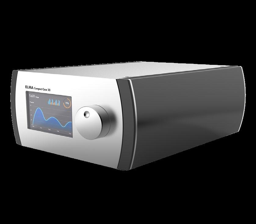
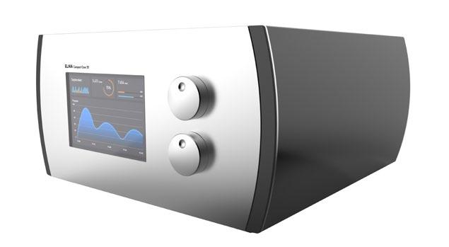
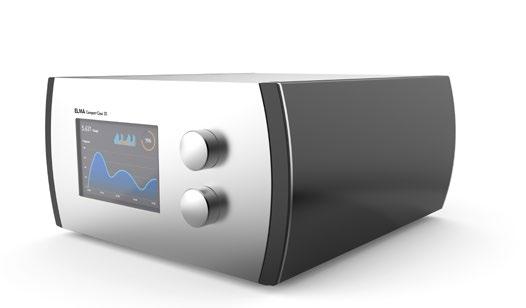
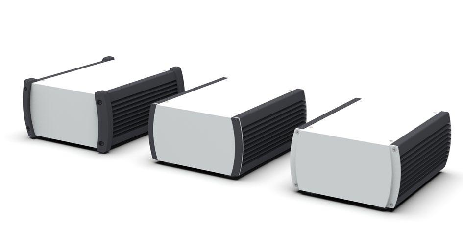
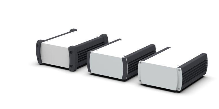
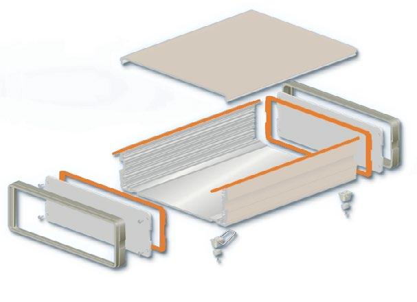
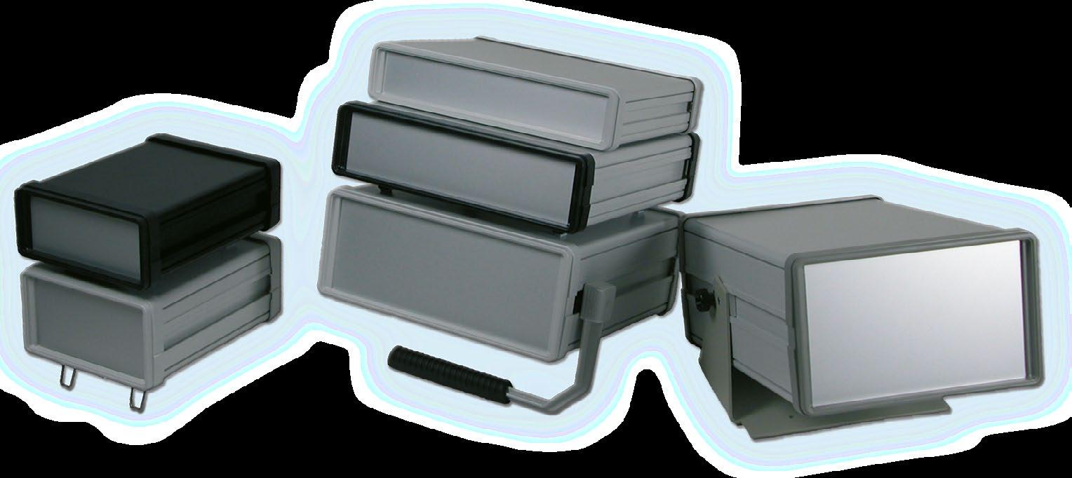
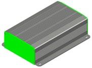
An attractive look in the environment makes working more beautiful and therefore more efficient. The compact design enclosure Compact Case 20 packs all the technology perfectly, because it is a flexible, robust and highquality aluminum case for measuring devices, control and service applications. It is suitable for both stationary and mobile use. The Compact Case 20 is available in three versions and several sizes. Scalable in depth, it offers perfectly adapted internal and external dimensions.
› Attractive design
› Aluminum sheet enclosure
› Extruded black anodized side and clear anodized cover panels
› Four standard heights with different depths
› Standard, comfort and rugged versions
› Only one type and size of screw
› Rugged version with covers made of elastomer, NBR 80 shore (RAL9005)
› Optional EMC protection
› Stackable
■ Standard | Comfort | Rugged
■ 2 plastic covers in PC | ABS for elevated aesthetic requirements
■ 4 rugged covers in elastomers for heavy loads
■ Optionally with increased EMC shielding (superior level)
■ Size
■ EMC protection
■ Front and rear panels
■ Test and measuring devices
■ Medical equipment
■ Audio and studio equipment
■ Applications in harsh environments
The standard version of Compact Case 20 offers conductively connected enclosure parts without additional seals. To increase the EMC shielding, optional versions with EMC gaskets are available.
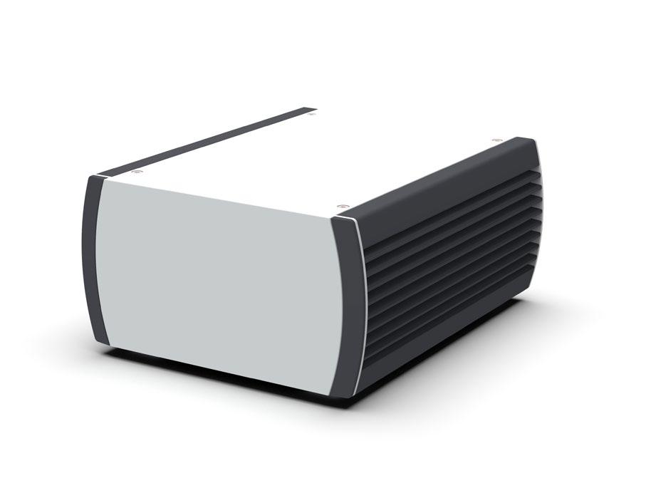
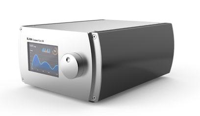
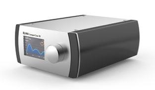
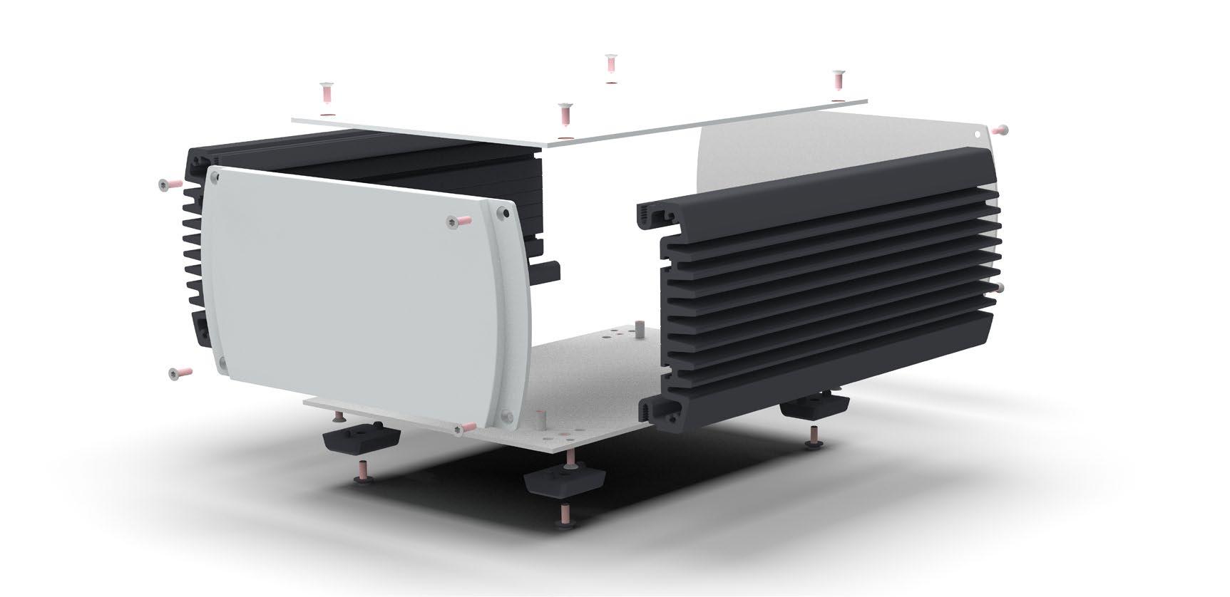
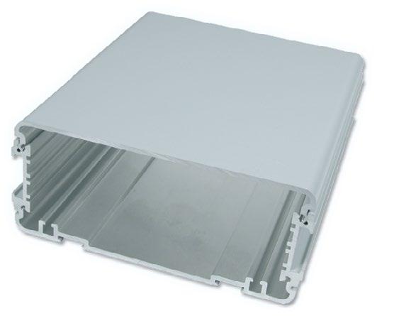
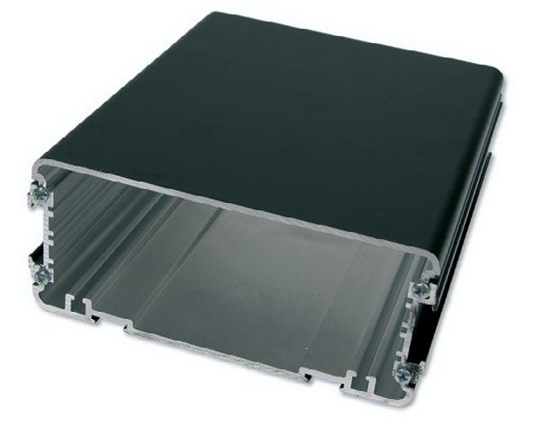
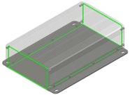
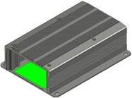
The Compact Case 20 embedded is a robust and highquality aluminum design housing for applications in the measurement, control and service areas. It is suitable for both stationary and mobile use. Thanks to the ribbed profile, the housing has a non-slip design and also ensures heat dissipation. The inclusion of square nuts allows for easy attachment of electronics or those components that require a heat sink.
It ensures reliable function - in the laboratory, treatment technology, in the audio sector as well as in the industrial sector.
› Two different standard heights: XS and S
› Three design variants for the front panels: Standard, Comfort, Rugged
› Groove for square nuts for fastening built-in components
› Stackable
› EMC-protection optional
Product variants
› 3 variants: Standard, Comfort, Rugged
› Optional with increased EMC protection (Superior Level)
› Variable depths and widths
Applications
› Audio Converters
› Embedded Controller
› Mess- und Überwachunsgeräte
Product variants
Standard versions
› 4 standard sizes with depths from 150 to 300 mm
› Other sizes on request
Embedded version
› 4 standard sizes with depths from 150 to 300 mm
› Other sizes on request
› Aluminum: Silver with black anodized side panels
› Comfort and Rugged versions with additional plastic covers
› Other colors on request
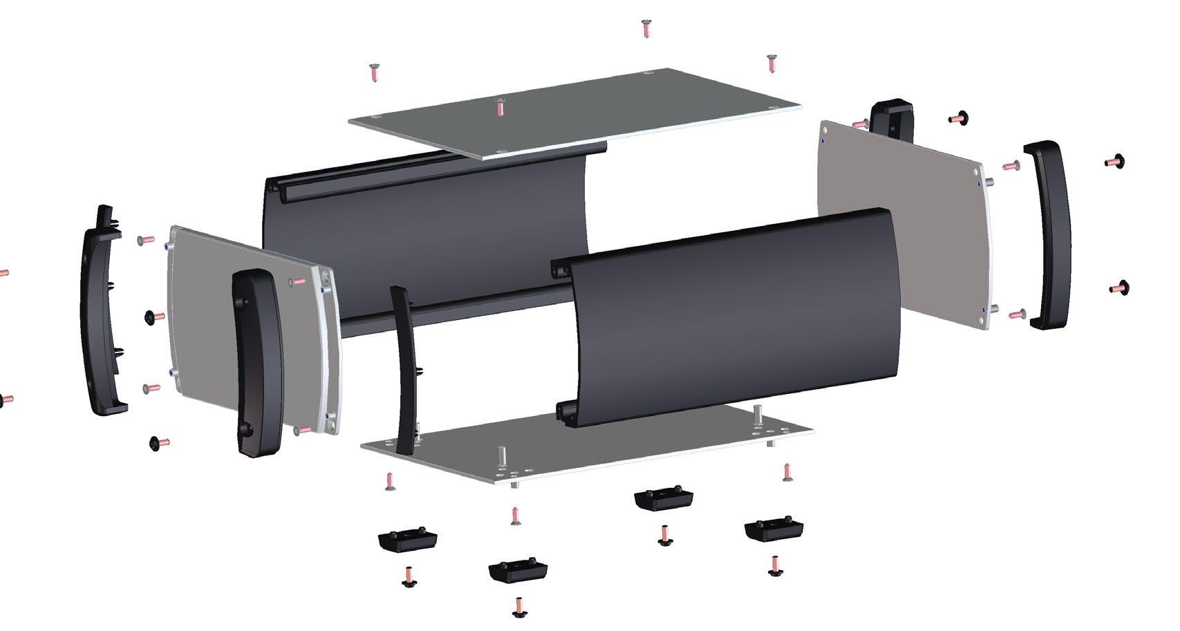
Product setup
Compact case 20
Compact Case 20 embedded
The Guardbox 33 is an aluminum enclosure with a timeless design in various sizes and excecutions. In addition to handiness, shape and color, it impresses with its robust construction. Even in the standard version of the box with ventilation slots, it achieves IP30 and can be upgraded to IP65 without openings (protected against dust and water jets). The enclosure also offers excellent EMC shielding.
› Sturdy
› Different sizes | scalable depth
› No visible screws
› Optional EMC shielding
› Heat dissipation with optional ventilation slots
› Mounting kits for Eurocards
› Checked for shock and vibration according to EN50155 | EN61373
› Adjustable folding feet
› Optional handles
■ Standard versions (6 different sizes)
■ IP54 combined with EMC protection
■ IP65
POSSIBLE CUSTOMIZATIONS
■ Depth
■ Different colors
■ Handles
■ Special mounting options (e.g. wall mounting or installation)
TYPICAL APPLICATIONS
■ Test and measurement equipment
■ Laboratory and service equipment
■ Equipment on train, trams, etc.
■ Enclosure 0: 129.5 x 55 mm
■ Enclosure 1: 129.5 x 71.5 mm
■ Enclosure 2: 230.5 x 55 mm
■ Enclosure 3: 230.5 x 89 mm
■ Enclosure 4: 183.5 x 111 mm
■ Enclosure 5: 230.5 x 41 mm
Tailored to customers needs, the Guardbox 33 is available in six different sizes.
Scope of delivery:
■ EMC level basic plus+
■ Top and bottom extrusions as well as front panels have conductive connections (this protects electronics from interference)
Scope of delivery:
■ EMC level advanced
■ Standard enclosure and EMC gasket set
■ EMC enclosure for demanding applications
Scope of delivery:
■ EMC level advanced plus+
■ Standard enclosure and IP54 / EMC set
■ EMC enclosure for demanding applications
■ Protects electronics from splash water and dust
IP65
Scope of delivery:
■ Protects electronics against dust and water jets from all directions
■ Bottom and cover: Light gray (RAL 7035), black (RAL 9005), stone gray (RAL 7032), other colors on request (MOQ: 10 pieces, no stock)
■ Frame: Light gray (RAL 7035), black (RAL 9011), stone gray (RAL 7030)
Complete enclosure with EMC base level. The sets contain all necessary parts.
Scope of delivery:
■ 1 basic enclosure without air perforation
■ 2 frames
■ 2 front / rear panels without air perforation
■ 1 set assembly material
4
CONFIGURATION
GUARDBOX 33 COMPILATION
1. BASIC ENCLOSURE type | depth | with or without air perforation
3. FRONT- AND REAR PANEL with or without air perforation | IP54 with or without EMC | IP65
5. ACCESSORIES
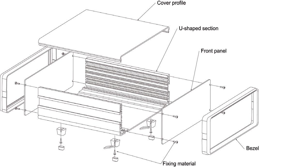
Cover profile
Deckprofil
U-shape
U-Profil
Front panel
Frontplatte
Befestigungsmaterial
Fixing material
Rahmen
Frame
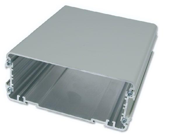
■ Aluminum profile
■ Powder coated
■ With or without air perforation slots in bottom
Scope of delivery:
■ 1 U-shaped bottom
■ 1 cover
Basic enclosure light gray:
Basic enclosure black: Basic enclosure stone gray:
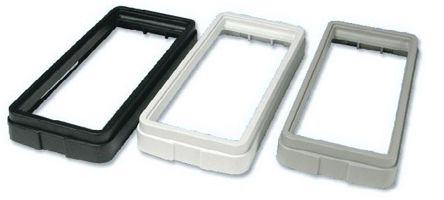
■ Protects the entire enclosure
■ High quality plastic, UL94 V-0
Scope of delivery:
■ 1 plastic frame
■ For one Guardbox 33 two frames have to be ordered
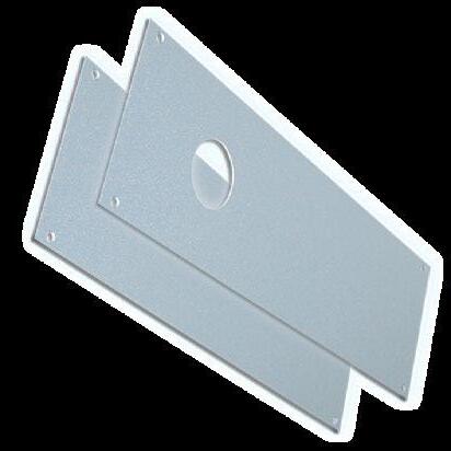
■ Front / rear panel of 2.5 mm (0.9'') anodised aluminum
■ Screwed on the front of the enclosure profiles (give the frame a required stability)
■ With or without air perforation
■ IP54 / EMC protection and IP65
Scope of delivery:
■ 1 front / rear panel with or without air perforation (for one two front / rear panels have to be ordered)
■ IP54 / EMC protection and IP65 set: 1 front, 1 rear panel, 2 self-adhesive seals, sealing hose, washers
■ Torque of mounting screws (IP protection): 0.7 to 0.75 Nm
REPLACEMENT SEALS IP54 / EMC
■ Foamed plastic conductive PET-PU black, UL94 V-0
■ Self-adhesive seals
REPLACEMENT SEALS IP65
■ Foamed plastic PCV gray, UL94 V-0
■ Self-adhesive seals
Enclosure
Gehäuse
Enclosure cover
Gehäusedeckel
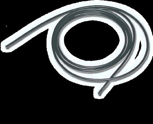
Sealing hose (silicone)
Dichtungsschlauch (Silikon)
Seal (self-adhesive)
Dichtung (selbstklebend) Scheibe
Washer
Blechschraube (Drehmoment: 0,70-0,75Nm) Rahmen
Tapping screw (torque: 0.7 - 0.75 NM)
Dichtungsfrontplatte
Sealing front panel
One set with all necessary materials for mounting one Guardbox 33.
Scope of delivery:
■ 4 feet (2 folding feet, UL94 V-0) incl. screws
■ 4 tapping screws to assemble the enclosure
■ Assembly material for internal extension (10 screws M3 x 8, 10 screw nut M3, 10 nut holders)
Scope of delivery:
■ Detailed assembly instruction (1 page)
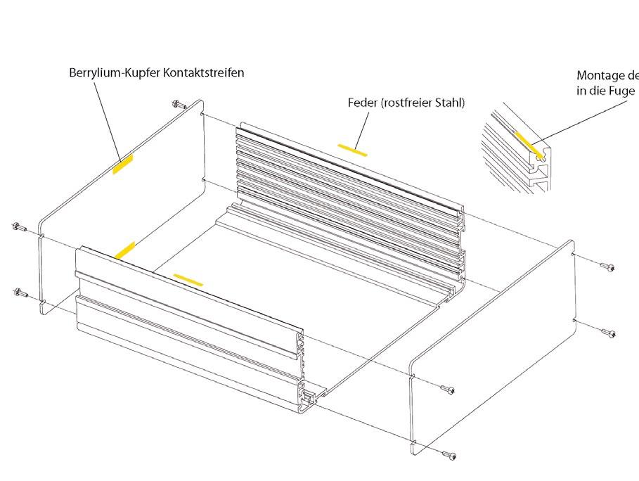
■ For EMC level advanced, when using no air perforations
■ For EMC level basic, when using air perforations
■ Increased EMC level by approximate 10 dB
Scope of delivery:
■ 4 berrylium-cooper contact strips
■ 2 stainless steel springs
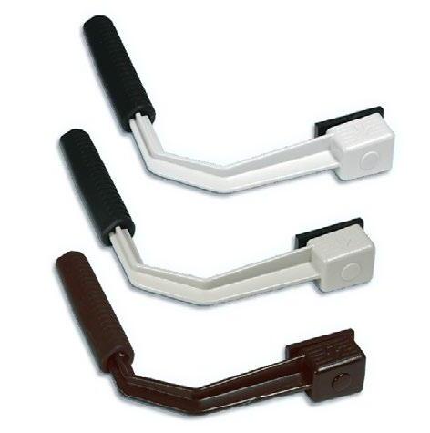
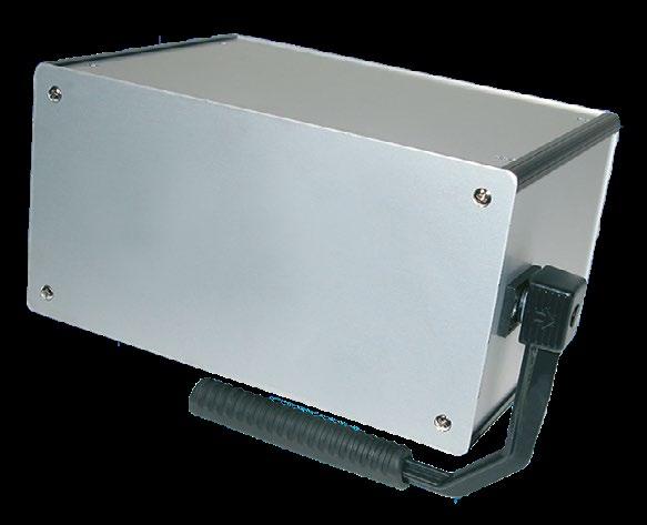
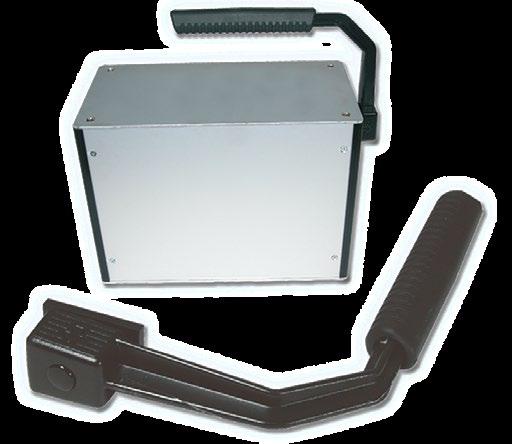
■ Powder-coated zinc die-cast
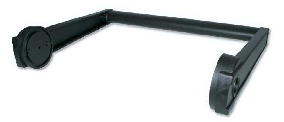
■ Handle piece: Black polyurethane, UL94 V-0
■ Handle can be attached to any position on the side of the groove
■ Handle is 90° detent (carrying position has a slight detent)
■ According to the enclosure in two widths available
Scope of delivery:
■ 1 pre-assembled handle with assembly material
Carrying capacity depends on distribution of load and handling. Decreases with dynamic stress.
■ Mounting brackets of 3 mm (0.11'') aluminum sheet
■ Angles are pushed to the side of the grooves and with 2 grub screws each M4 x 6 mm positioned
■ With mounting brackets as a built-in enclosure in control panels etc. usable
Scope of delivery:
■ 2 mounting brackets
■ 4 screws M4 x 6 mm
■ Sliding blocks expand the fastening options
■ Handle channel stones are pushed into the side groove of the enclosure
■ Foot slot nut are used instead of the feet
Scope of delivery:
■ Sliding blocks incl. screws
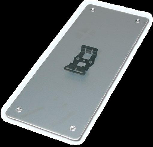
■ For the installation of Eurocards 100 x 160 mm (3.93 x 6.29'') with connectors according to IEC60603-2
■ Card carrier 1 mm (0.03'') galvanized sheet steel for the installation of the enclosure 0 - 4
■ Other use: Vertical mounting of cards in enclosure size 4 (fastening lugs have to be removed)
Scope of delivery:
■ 1 card carrier
■ Assembly material in set
■ A mounting plate has to be ordered if cards are to be mounted horizontally in enclosure sizes 2, 3 and 4
Bemerkung: Für die vertikale Montage der Karten in der Gehäusegrösse 4, müssen die Befestigungslappen entfernt werden Kartenträger
Fastening lugs (cards mounted vertically)
Befestigungslappen Karten werden vertikal befestigt
Note: For vertical mounting of cards in enclosure size 4, fastening lugs have to be removed
Befestigungslappen Karten werden vertikal befestigt
Bemerkung: Für die vertikale Montage der Karten in der Gehäusegrösse 4, müssen die Befestigungslappen entfernt werden
Card mounting vertically | enclosure 4
■ In each pair, one card guide is fitted with a card locking mechanism
■ Light gray UL94 V-0
Scope of delivery:
■ Card guides in pairs
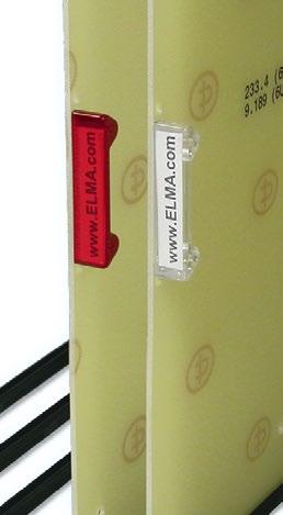
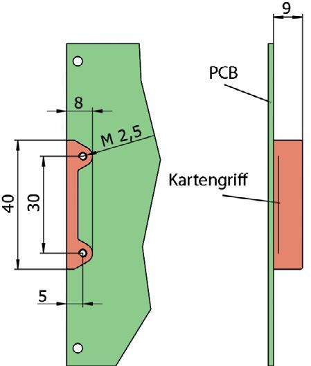
■ Card handles made of transparent plastic for better access and labeling of the plug-in plates
Scope of delivery:
■ 1 card handle
■ Two screws per card handle M2.5 x 5 are needed (ordered separately)
■ Galvanised sheet steel plug-in sub-unit allowing 3 U plug-in units (Eurocards 100 x 160 mm with IEC60603-2 connectors and flat or extruded front panels) to be mounted horizontally in the Guardbox 33
■ Installation height 12 HP
■ Enclosure front panel 129.2 x 61 mm (5.08 x 2.40'') is made from 2.5 mm thick anodised sheet aluminum
Scope of delivery:
■ 1 plug-in card carrier sub-unit
■ 1 front panel with opening for enclosure 1
■ Assembly material for sub-unit
Mounting set for plug-in units (single Eurocards):
Sub-unit for enclosure 3 and 4:
■ The sub-unit can also be used for enclosure 3 and 4. (front panel can be manufactured with openings to your own specifications)
■ The corresponding mounting plate must be ordered to install the plug-in block
■ Card stoppers are used for card fixation of double Eurocards, if these are installed directly in enclosures 2, 3 and 5
Scope of delivery:
■ 4 card stopper made of aluminum profile
■ 4 hexagon socket set screws
■ 1 hexagon socket key
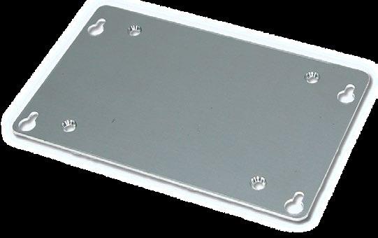
■ Mounting plates of 2 mm (0.07'') thick sheet aluminum
■ Dimensions correspond to the respective enclosure size
■ Position of the slots allows various mounting arrangements and good air circulation
■ The mounting plate is screwed to the grooved enclosure profile
Scope of delivery:
■ 1 mounting plate, aluminum raw
■ Assembly material included in the basic set
Front panel screws:
■ Earthing terminal enables EN / VDE / NIV-compliant earthing
Scope of delivery:
■ 1 earthing nut M3.5
■ 1 threaded bolt M3.5
■ 1 clamp bracket
■ 2 serrated washers
■ 1 nut M3.5
■ 1 earthing symbol
- 5 Earthing terminal
Enclosure 0 | 2 Enclosure 1
Enclosure 3
Enclosure 4
Enclosure 5
4
■ Protection against contact and foreign bodies according to IEC60529
■ Protection against water according to IEC60529
Evaluation of classification:
■ The test results according to the standard do not entirely exclude leaks and an individual test is therefore recommended in critical cases (with the actual equipment layout)
■ The protection class for cabinets and enclosures is specified by IP (International protection) and two indices
Example IP55
Protection against penetration by water jets from all directions
Complete protection against contact with internal parts and against dust deposition

The Guardbox 33 was tested after the following tests:
■ Vibration EN50155 (EN61373)
■ Shock EN60068-2-27
■ IP protection IEC60529
■ Salt spray test DIN50021
Detail information to environmental and mechanical tests:
Tests
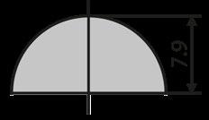
Vibration EN50155 (EN61373, category 1, class B)
Shock EN60068-2-27
IP protection IEC60529
Information
Eff. acceleration: 7.9 m / s2 | Duration: 5 h / axis
Frequency: 5 to 150 Hz
Axis of stimulation: X, Y, Z
Shockform: Halfsinus
Acceleration: 150 m / s2 | Duration: 11 ms
Number of shocks: 3 / axis | Total shocks: 18
IP65: Guardbox 33 with IP65 sealing set
IP54: Guardbox 33 with IP54 / EMC sealing set
Salt spray test DIN50021 Salt concentration: 5 g / l | Duration: 96 h Temperature: +35 °C
The Guardbox 33 easy is a small, but very robust enclosure that is available in different sizes. The bottom is shaped as a U-profile and thus gives the enclosure a stable hold. The lid is fixed with the front and back plate fastening. With its inner guide rails, it easily accommodates PCBs (Eurocard format or other components). A wide range of accessories enables an optimal adaptation to any application.The vibration-proof housing is characterized by its simple structure and ease of servicing.
› Strudy
› Handy
› Service friendly
› Single or double Eurocards
› Adjustable folding feet
› Optional handle
› Box, front and back plates completely anodized
■ 6 different sizes
POSSIBLE CUSTOMIZATIONS
■ Mounting plates
■ Single or double Eurocards
TYPICAL APPLICATIONS
■ Test and measurement equipment
■ Laboratory and service equipment
■ Equipment on train, trams, etc.
■ Enclosure 0: 129.5 x 55 mm
■ Enclosure 1: 129.5 x 71.5 mm
■ Enclosure 2: 230.5 x 55 mm
■ Enclosure 3: 230.5 x 89 mm
■ Enclosure 4: 183.5 x 111 mm
■ Enclosure 5: 230.5 x 41 mm
Tailored to customers needs, the Guardbox 33 easy is available in six different sizes.

Scope of delivery:
■ 1 basic case anodized
■ 2 front / rear panels clear anodized
■ 1 set with 4 feets (2 rocking, UL94V-0) incl. screws
■ Clear anodized
■ Other colors on request
■ For Guardbox 33 easy enclosure sizes 1 to 4
■ Side parts made of plastic black
■ Handle extrusion in aluminium, anodized black
■ Handle can be attached at any position on the lateral groove
■ Handle latches every 30 °
Scope of delivery:
■ 1 pre-assembled handle with assembly material
■ The sliding blocks provide an optional means of attachment
■ The blocks are inserted in the handle slot on the side of the case respectively in place of the feet slot
■ Feet nuts are used instead of the feet
Scope of delivery:
■ Sliding blocks incl. screws
■ Card stoppers serve to additionally fix the double Eurocards if they are installed directly in the enclosure 2, 3 and 5
Scope of delivery:
■ 4 extruded card stoppers
■ 4 hexagon socket set screws
■ 1 hexagon socket key
0 - 5 33-618
■ Protective earthing terminal facilitates enable EN / VDE / NIV-compliant earthing
Scope of delivery:
■ 1 earthing nut M3.5
■ 1 threaded bolt M3.5
■ 1 clamp bracket
■ 2 serrated washers
■ 1 nut M3.5
■ 1 earthing symbol
- 5 Earthing terminal 33-619
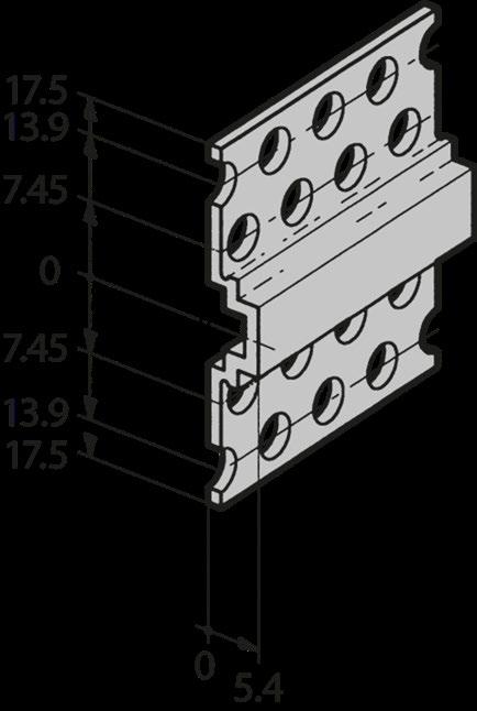
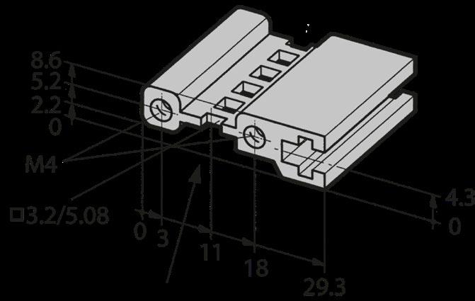
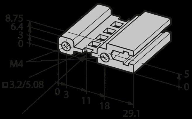
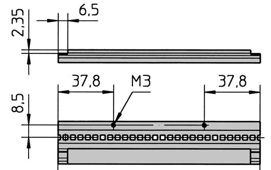
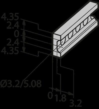
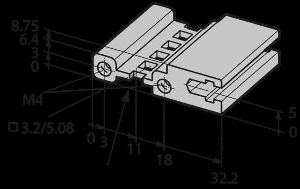
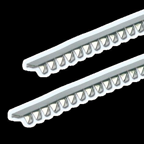
CROSS SECTIONS OF EXTRUSIONS
The Varietybox 35 consists of 4 structurally identical corner profiles and 6 flat sheets. The multifunctional corner profiles and flat sheets are made of aluminum. Thanks to the simple structure, assembly is extremely fast. The Varietybox 35 is a cost-effective solution and easy to modify.
› Multifunctional corner extrusion made from aluminum
› Flat plates made from aluminum sheet metal 2 mm
› Fast assembly (1 to 2 min)
› Very cost effective solution
› Easy to modify
› IP40 (without ventilation slots) | IP30 (with ventilation slots)
› EMC level basic when using clear passivated corner extrusions
› Hard and wear resistant solution when using anodized corner extrusions
PRODUCT VARIETY
■ Predefined standard or custom sizes
POSSIBLE CUSTOMIZATIONS
■ Variable sizes
■ Anodized or passivated
TYPICAL APPLICATIONS
■ Test and measurement equipment
■ Control instruments
■ Service equipment
Standard dimensions:
■ Profiles: Black or clear anodized
■ Customizations on request
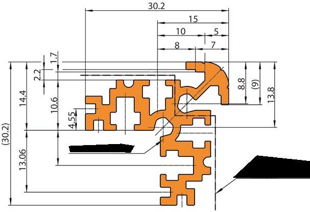
MULTIFUNCTIONAL CORNER EXTRUSION
■ Functions symmetrical
■ Can be mounted twisted
■ Size: approx. 30 mm
■ Outer radius 5 mm
■ Material: Aluminum
■ Different colours (anodized or painted)
■ Conductive or wear resistant
■ Take-up of sheet metal 1.5 or 2 mm
■ Mounting through insertion
■ Use of flat sheet metal
■ Different materials, surfaces, colors


■ Groove for direct insertion of PCB’s
■ Sufficient space for double sided PCB’s
■ Simple insertion until the card stopper

■ Groove for direct sliding of a mounting panel or a PCB
■ Sufficient place for feet as well as for press-in nuts, screw heads, etc.

■ Mounting of an earthing terminal M3.5
■ Secure connections to the ground
■ Hole for direct mounting of the end plates
■ Mounting with 4 screws M4
■ Use of flat sheet metal
■ Different materials, surfaces, colors
■ End plates als can be used as a side panel (by relating the whole box by 90°)
■ Hole for direct mounting of an intermediate plate
■ For additional stability
■ For integration of further features


CONFIGURATION
VARIETYBOX 35 COMPILATION
1. CORNER EXTRUSIONS different length and versions
2. EXTRUSIONS PLATES with or without mounting holes | air perforation | holes for feet and handles
3. FRONT / REAR TERMINATIONS PANEL
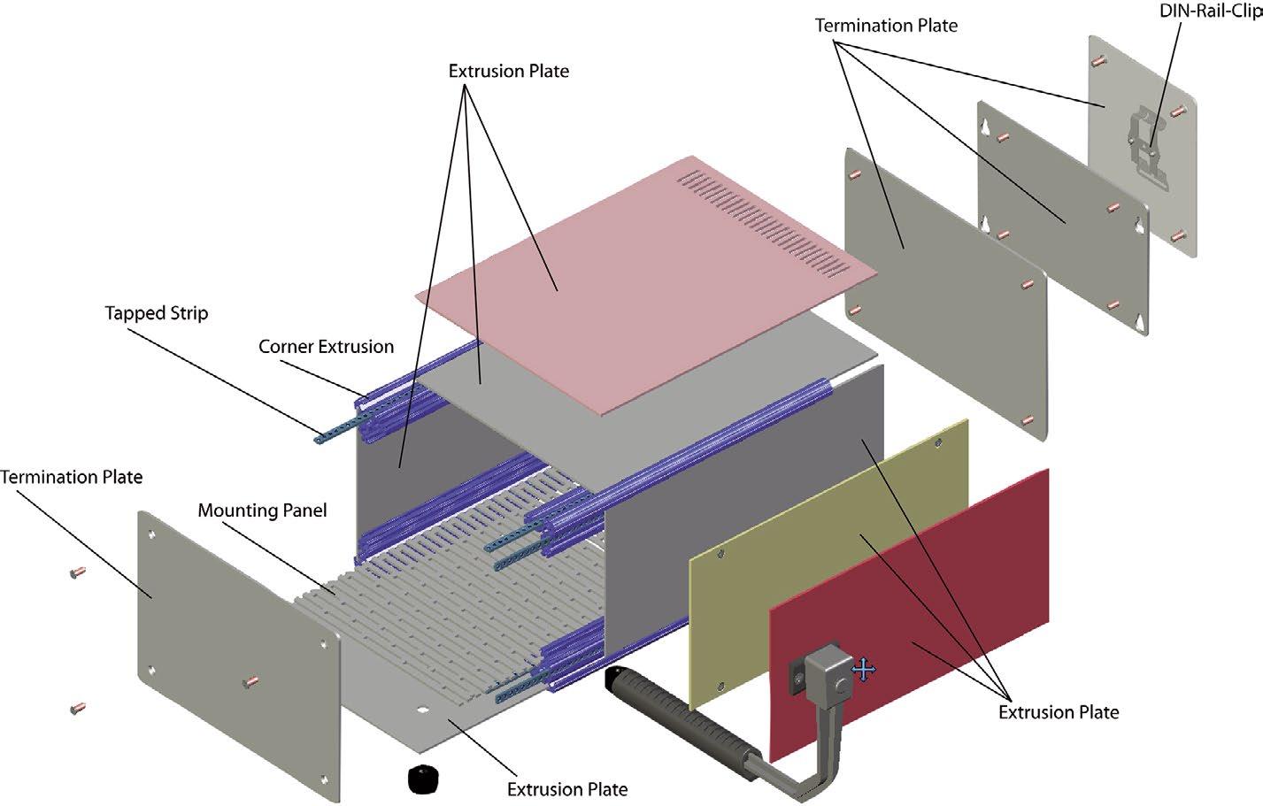
4. ACCESSORIES
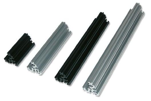
CORNER EXTRUSIONS
■ Extruded aluminum
■ Versions: Clear anodized / black anodized / clear passivated (conductive)
■ 7 different length
■ Other sizes, colors and surface treatments on request
Scope of delivery:
■ 1 corner extrusion
■ For one Varietybox 35 are 4 corner extrusions necessary (order separately)
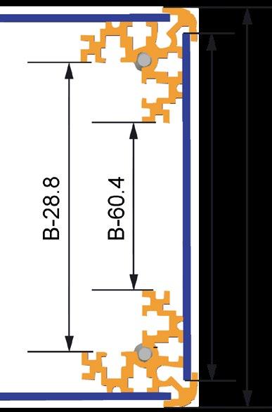
EXTRUSIONS PLATES
■ Without holes inserted into extrusion
■ With or without air perforation
■ With or without holes for mounting feet
■ With holes for screwing (for more stability and for direct access)
■ Material: Aluminum 2 mm | front clear anodized | rear conductive
■ Other sizes, colors and surface treatments on request
Scope of delivery:
■ 1 extrusion plate
■ For one Varietybox 35 are 4 extrusions plates necessary (order separately)
Without holes With mounting holes With air perforation With holes for feet With holes for handles
EXTRUSION PLATES WITHOUT HOLES
■ For simple insertion into the corner extrusions
Scope of delivery:
■ 1 extrusion plate
For mounting of single / double Eurocards:
EXTRUSION
EXTRUSION PLATE WITH MOUNTING HOLES
■ For more stability
■ Removable for maintenance and accessibility
Scope of delivery:
■ 1 extrusion plate
180
240 x 120 9.44 x 4.72 237.5 x 120 9.35 x 4.72 35-20023
240 x 180 9.44 x 7.08 237.5 x 180 9.35 x 7.08 35-20024
240 x 240 9.44 x 9.44 237.5 x 240 9.35 x 9.44 35-20025
EXTRUSION PLATE WITH AIR PERFORATION
■ For thermal optimisation
■ IP30 is ensured with air perforation
Scope of delivery:
■ 1 extrusion plate
120 x 300 4.72 x 11.81 35-20044
180 x 240 7.08 x 9.44 35-20026
180 x 300 7.08 x 11.81 35-20046
240 x 180 9.44 x 7.08 35-20027
240 x 240 9.44 x 9.44 35-20028
300 x 300 11.81 x 11.81 35-20045
EXTRUSION PLATE WITH HOLES FOR FEET
■ For mounting of enclosure feet
Scope of delivery:
■ 1 extrusion plate
x
7.08 x 9.44 35-20029
x 300 7.08 x 11.81 35-20043
x 240 9.44 x 9.44 35-20030
x 300 9.44 x 11.81 35-20039
x 300 11.81 x 11.81 35-20040
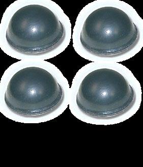
Enclosure feet:
■ Black plastic, UL94 V0
■ Easy and fast mounting
■ Mounting without tools
■ Scope of delivery: Set 4 pieces plastic feet incl. push rivet
Set of enclosure feet, black (RAL 9005) 63-528 Set of enclosure feet, light gray (RAL 7035) 63-529
EXTRUSION PLATE WITH HOLES FOR HANDLES
■ For mounting a handle
Scope of delivery:
■ 1 extrusion plate
90 x 180 3.54 x 7.08 35-20031
90 x 240 3.54 x 9.44 35-20032
120 x 180 4.72 x 7.08 35-20033
120 x 240 4.72 x 9.44 35-20034
180 x 240 7.08 x 9.44 35-20035
Carrying handle:
■ Zinc die-cast, powder-coated
■ Handle piece: Black polyurethane, UL 94V-0
■ Handle is 90° detent (carrying position has a slight detent)
■ Following the enclosures sizes there are handles available in two widths
■ Scope of delivery: Pre-assembled handle with assembly material
Carrying capacity dependent on distribution of load and handling.
Assembly material for handle:
■ 2 screws per 1 handle
FRONT / REAR TERMINATIONS PANEL
■ Aluminum sheet metal 2 mm
■ Front clear anodized | rear conductive
■ Other sizes, colors and surface treatments on request
Scope of delivery:
■ 1 front / rear terminations panel
■ For one Varietybox 35 are 2 terminations panel (1 front / 1 rear) necessary
TERMINATION PLATES STANDARD
Scope of delivery:
■ 1 termination plate
■ Per termination plate 4 screws are needed (order separately)
74 x 74 2.91 x 2.91 35-10001
74 x 104 2.91 x 4.09 35-10002
74 x 134 2.91 x 5.27 35-10003
74 x 194 2.91 x 7.63 35-10004
74 x 254 2.91 x 10 35-10005
104 x 104 4.09 x 4.09 35-10006
104 x 134 4.09 x 5.27 35-10007
104 x 194 4.09 x 7.63 35-10008
104 x 254 4.09 x 10 35-10009
134 x 134 5.27 x 5.27 35-10010
134 x 194 5.27 x 7.63 35-10011
134 x 254 5.27 x 10 35-10012
134 x 314 5.27 x 12.36 35-10022
194 x 194 7.63 x 7.63 35-10024
194 x 254 7.63 x 10 35-10013
194 x 254 7.63 x 12.39 35-10023
254 x 254 10.00 x 10 35-10019
254 x 314 10.00 x 12.36 35-10020
314 x 314 12.36 x 12.36 35-10021
TERMINATIONS PANEL FOR EUROCARDS MOUNTING
■ Direct sliding of single / double Eurocards
Scope of delivery:
■ 1 terminations panel
■ Per erminations panel 4 screws are needed (order separately)
FRONT / REAR TERMINATIONS PANEL
TERMINATIONS PANEL FOR DIN-RAIL MOUNTING
■ Incl. riveted steel DIN-clip
■ Suitable for top hat rails 35 mm according to IEC60715 / EN50022
Scope of delivery:
■ 1 terminations panel
■ Per terminations panel 4 screws are needed (order separately)
TERMINATIONS PANEL FOR WALL MOUNTING
Scope of delivery:
■ 1 terminations panel
■ Per terminations panel 4 screws are needed (order separately)
Other dimensions and arrangements on request
SCREWS FOR MOUNTING TERMINATIONS PANEL
■ Small head
■ Per termination panel 4 screws are needed and 8 screws per Varietybox 35 (order separately)
■ Self adhesive bumpon
■ Black polyurethane, UL94 HB
Scope of delivery:
■ 1 bumpon
■ For EMC-sealing from extrusion to extrusion plates
■ For higher IP-protection (upon request, still in engineering process)
■ Firmer securing of non-screwed extrusion plates
■ Conductive sealing
Scope of delivery:
■ 1 sealing gasket (conductive or non-conductive)
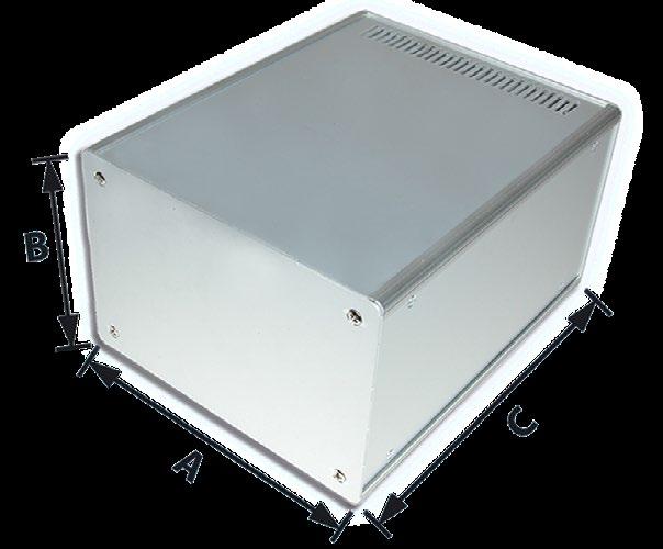
■ Mounting plates made of 2 mm (0.07'') thick sheet aluminum
■ Dimensions correspond to the respective mounting terminations panel
■ Position of the slots allows various mounting arrangements and good air circulation
■ Mounting plate is screwed to corner extrusion with M3 nut and screw in 4 places
Scope of delivery:
■ 1 mounting plate, aluminum raw
■ Card stop are used for card or mounting plate fixation when directly inserted
Scope of delivery:
■ 1 card stopper aluminum
■ 1 cross recessed screw M3 x 6
■ 1 square nut M3
■ 2 plastic gliders
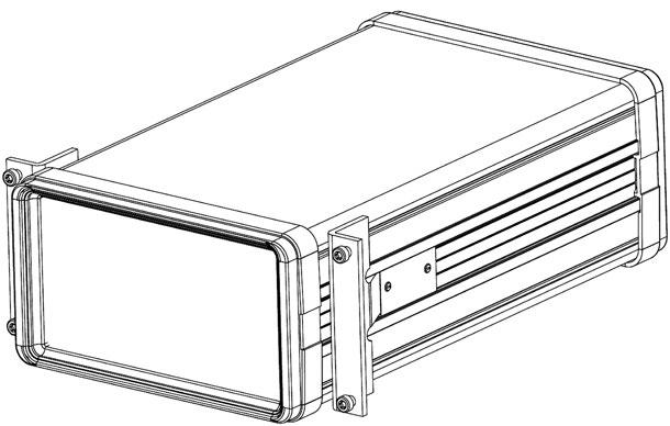
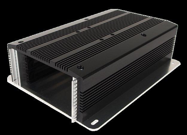
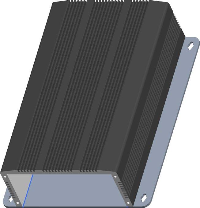
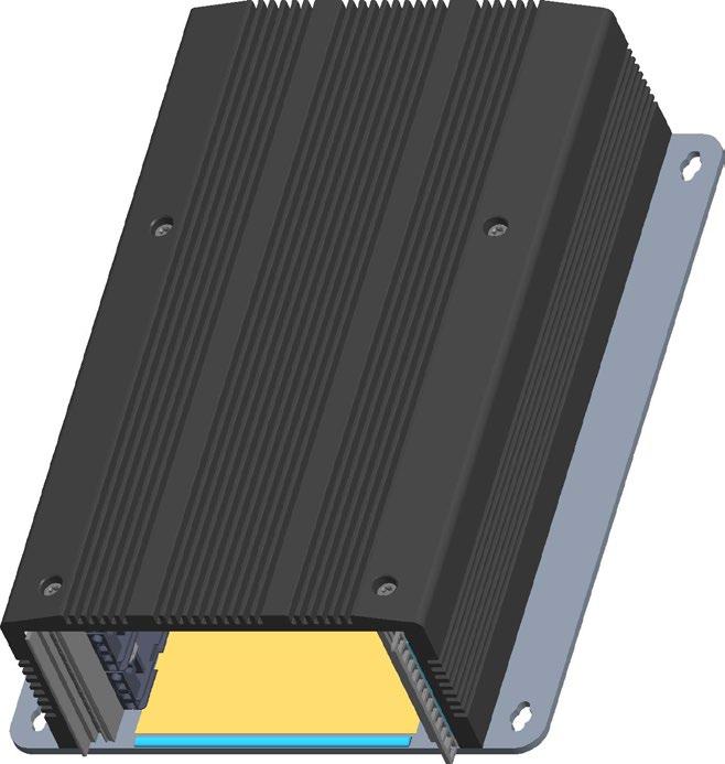
ElosBox 54 is an embedded enclosure for one to three controller cards. The aluminium profile housing has been specially developed for the industrial use of embedded controller cards. Depending on the version, up to 3 IEEE cards can be used. In addition to up to 3 slots for controller cards, the "box" can be equipped with a suitable mounting plate (e.g. CompactPCI) and a suitable power supply.
The basic version, in combination with front and rear panels, allows controller cards with connectors or operating elements to be mounted. The use of special seals also makes it possible to achieve higher IP classes with this version.
Optionally, the enclosure allows heat dissipation via ventilation holes or actively with a fan. It also provides excellent EMC protection.
■ Standard enclosure with holes for front and rear panel
■ IEEE version with profiles for card guides and plug-in modules
■ Optionally with ventilation holes
■ Compact dimensions
■ For 1 to 3 Controller boards
■ IEEE profiles for plug-in modules (optional)
■ Optional EMC protection
■ Matching backplanes and power supplies on request
■ Special depths available on request
■ Pressed extruded profile on aluminium base panel
■ Black coloured, other colours optionally available
■ Optional built-in profiles and threaded strips for IEEE plug-in units
■ Optional front and rear panels
■ Controller for passenger information
■ Miniserver
■ Control computer
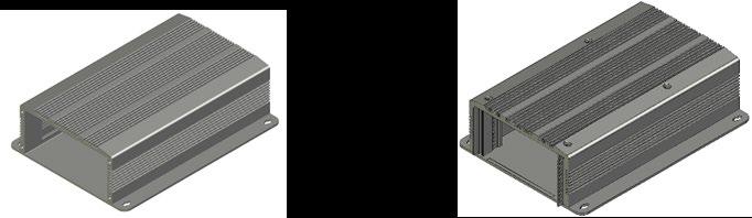
PRODUKTVARIANTEN
■ Grundplatte
■ Gehäusekörper pulverbeschichtet, schwarz RAL 9005
■ Montagematerial
■ IEEE Profile & Gewindestreifen für 19" Baugruppen (nur IEEE Version)
ARTIKELBEZEICHNUNG ARTIKELNUMMER
ElosBox 54 Grundgehäuse 73mm 190.5mm 257mm
54E-100-257
ElosBox 54 Grundgehäuse mit Lüftungsschlitze 73mm 190.5mm 257mm 54E-101-257
ElosBox 54 Grundgehäuse 73mm 190.5mm 257mm 54E-110-257
ElosBox 54 Grundgehäuse mit Lüftungsschlitze 73mm 190.5mm 257mm 54E-111-257 Grundgehäuse
ARTIKELBEZEICHNUNG
Front-/ Rückplatte 1 Stück inklusive 4 Befestigungsschrauben
Dichtungen ElosBox 54 EMV-IP
Dichtungen ElosBox 54 IP
IP XX
Isolationsfolie Mylar Typ A 0.125 mm 95x160 mm selbstklebend
ARTIKELNUMMER
54E-800 (für beide Seiten 2 Stück benötigt)
Dichtungen für Front- & Rückplatte (397 mm): 54E-900 (2 Stück benötigt)
Dichtungen für Tiefe (257 mm): 54E-901 (2 Stück benötigt)
Dichtungen für Front- & Rückplatte (397 mm): 54E-902 (2 Stück benötigt)
Dichtungen für Tiefe (257 mm): 54E-903 (2 Stück benötigt)
54E-910
19'' technology in precision.
Das Nonsequam ab idit quam fuga. Nem quate comnihitis quia sit, abore volo earumqu odiorem porecum nimus aut qui aut et, nonse volupta tempeli busani nobis et aliati numque post, ut ute cus vitiatur antium volupta nullestiis magnisc ientiore estrum eatur, ipic tenimet occus natios ma dendict otatece pereror ad ma ate aut fuga. Musam andae pos et hitasit idelit, unt.
19'' subracks are all based on the standard IEC 60297. Thanks to decades of experience, the characteristics of the individual families have been optimized for different applications. The flexible structure of the subrack systems with individual extension kits allows a customer-specific configuration. Due to the high level of integration and wide range of accessories, all components fit together perfectly.
The scalable, robust 19'' subracks, PCB housings or slide-in chassis are suitable for use in almost any kind of environment: Industrial automation, test and measurement technology, transport, energy, defense, communication and medicine. Of course, the enclosures support standards like IEC, IEEE or AdvanvedTCA.
› IEC 60297 conform
› Modular construction
› Customized solutions on request
› Large range of accessories
TYPE COMPARISON
MAGIC-KIT 11 | SPIRIT-KIT 11
SYSTEMKIT 12K
SYSTEMKIT 12K RAIL
The 19'' system enclosure with 1 U combines flexibility with comprehensive EMC protection. It can be used as a 19'' rack or desktop case. It is made of sheet metal and a customizable aluminum front panel.
The Slimkit 11 FTTX was specially developed for applications in the field of fiber optic distribution systems. Customer-specific adjustments can be easily implemented on the basis of this platform.
The Ecokit is a shielded subrack with side panels made of aluminum. A cost-effective solution for circuit board assembly systems with Eurocard depths of 160, 220 or 280 mm.
These two shielded subracks are ideal for IEC applications (Magic-Kit) or for IEEE applications (Spirit-Kit). The EMC subracks are made of sheet steel for extremely fast assembly and EMC shielding without seals.
The best basis for every customer-specific 19'' subrack for cPCI, VME or VME64 with high environmental expectations. It has many advantages such as EMC shielding or climatic and mechanical resistance.
Based on the Systemkit 12K, the Systemkit 12K Rail has been specially designed and tested for applications in the railway sector. It meets all technical requirements according to EN50155.
PAGE 100
PAGE 106
PAGE 109
PAGE 118
PAGE 126
PAGE 150
General accessories can be found in the brochure ''General accessories'' or on request.
The 19'' | 1 U basic subrack impresses with its diverse application options. Through the addition of rear panel, cover and mounting chassis, it can be expanded to a completely closed enclosure.
The Slimkit 10 adapts to customer-specific requirements really simply thanks to EMC properties and almost unlimited combinations.
› Front panel: Aluminum
› Frame construction: Pre-galvanized sheet steel
› Vibration-proof
› EMC shielding without gaskets
› Fast assembly
› Easy access
› Front / rear panel can be removed for mechanical processing
■ 19'' insert variants
■ Desktop variants
■ With or without ventilation openings
TYPICAL APPLICATIONS
■ Telecommunications
■ Audio and radio equipment
■ Signal converters
■ Test and measurement equipment
■ Width: 19'' (enclosure width 440.5 mm)
■ Height: 1 U (2 U on request)
■ Depth: 240 or 360 mm
COLORS
■ Pre-galvanized sheet steel
■ Front panel aluminum
SLIMKIT 10 COMPILATION
1

■ 0.75 mm pre-galvanized sheet steel
■ With holes for fastening of mounting chassis, feet, earthing terminals, front / rear panel, top cover
Scope of delivery:
■ Basic tray
■ Assembly material for mounting front / rear panel, mounting chassis, top cover (12 round head SHEETtracs® screws torx T10 (3 x 6))
1 U 240 9.45 Solid - - 10-91100-00
1 U 240 9.45 Perforated 18095 28.04 10-91101-00
1 U 360 14.17 Solid - - 10-91110-00
1 U 360 14.17
■ 1 mm aluminum
■ Front: Clear anodized | powder coated black (RAL 9005) | powder coated light gray (RAL 7035)
■ Rear: Conductive
■ With or without black handles
■ Customized front panels on request
Scope of delivery:
■ Front panel
■ Handle set (2 black U-handles, 4 countersunk screws torx T8 (M2.5 x 8))
■ Assembly material included in the basic tray set
1
Clear anodized With 10-46100-00
1 U Clear anodized Without 10-451-00
1 U Black powder coated With 10-46160-00
1 U Black powder coated Without 10-451-60
1 U Light gray powder coated With 10-46130-00
1 U Light gray powder coated Without 10-451-30
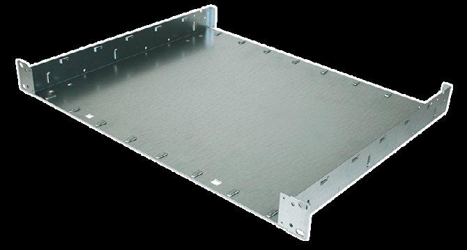
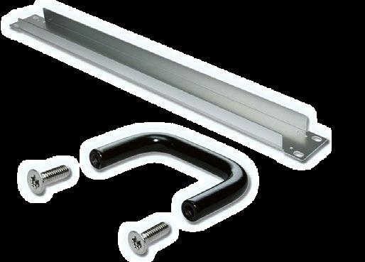
■ 0.75 mm pre-galvanized sheet steel
■ Customized rear panel on request
Scope of delivery:
■ Rear panel
■ Assembly material included in the basic tray set
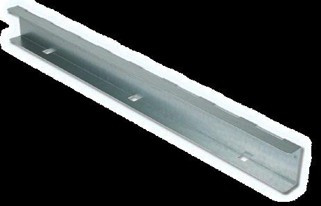
■ 0.75 mm pre-galvanized sheet steel
■ Customized rear panel on request
Scope of delivery:
■ Top cover
■ Assembly material included in the basic tray set
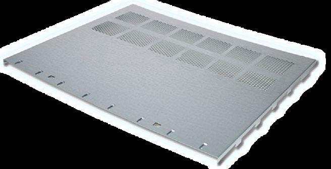
■ Inclusion of components
■ Mounting chassis 240 mm can be mounted with depth 360 mm
■ 1.25 mm pre-galvanized sheet steel
■ Mounting chassis with customized cut outs on request
Scope of delivery:
■ Mounting chassis
■ Assembly material included in the basic tray set
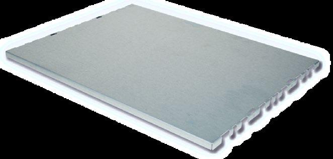
■ Enables enclosures to be grounded in conformance with EN / VDE / NIV
Scope of delivery:
■ 1 press-in threaded bolt M4
■ 2 serrated lock washers
■ 2 nuts M4
■ 1 clamp
■ 1 protective conductor symbol
Earthing set according to EN / VDE / SEV 63-174
■ Folding feet / non-folding feet
■ Color: Light gray (RAL 7035), black (RAL 9005)
■ Fiberglass reinforced plastic, UL94 V-0
■ Up to 30 kg load capacity per set
Scope of delivery:
■ 1 set of feet
■ Assembly material: 8 cross recessed countersunk PT-screw 3.5 x 8
Enclosure feet 4 x b Light gray (RAL 7035) 63-019
Enclosure feet 4 x b Black (RAL 9005) 63-321
Enclosure feet 2 x a + 2 x b Light gray (RAL 7035) 63-018
Enclosure feet 2 x a + 2 x b Black (RAL 9005) 63-320

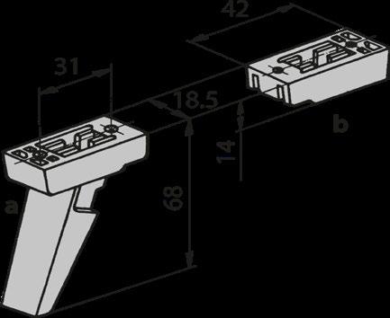
■
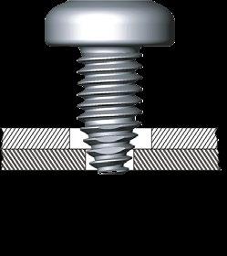


Cable end distributor for fiber optic cables in the 19'' | 1 U format. The customizable rack was specially designed for the division of fiber optic cables. The pull-out drawer allows a convenient maintenance of the cables and serves as a generous storage space for the packaging of radii of the glass fibers. Thanks customized expansion variants, different plug connections and labels are possible.
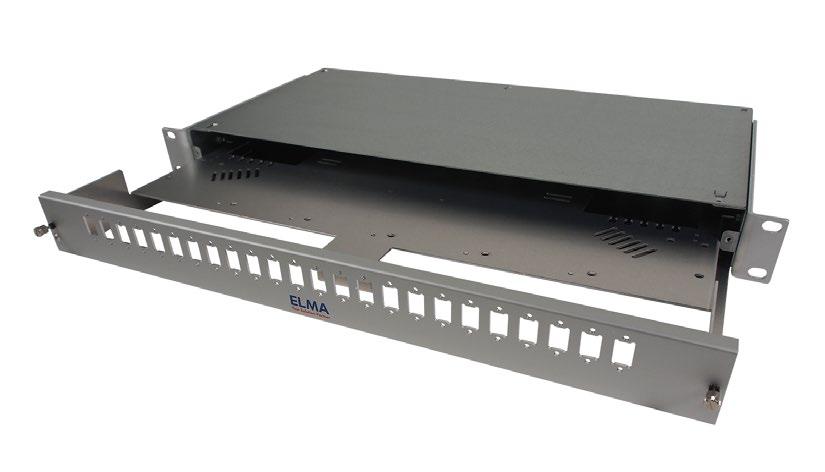
› Light construction
› Installation in every 19'' chassis or rack system
› Variable depth thrue movable 19'' angle bracket
› Provided to hold splice trays or LWL-cable termination
› Telescopic and tiltable pull-out tray
› With cable storage
› Option of cable fastening and entry prepared
› Front resettable
Executions
SIZES
■ 1 U | 19'' | 220 mm depth
SCOPE OF DELIVERY
■ Steel sheet enclosure SVZ
■ Front profile aluminum
■ Reusable cardboard packaging
The Ecokit is a subrack with side panels of aluminum. It is a cost-effective solution for Eurocards systems with depths of 160, 220 or 280 mm
The special shapes on the side wall make it possible to securely fasten the front extrusions with only half as many screws.
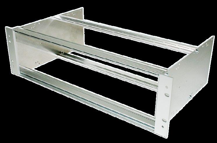
› Side walls are of 2 mm aluminum
› 19'' height extrusions with 3 mm overlay (standard only)
› With cover plates suitable for use with vibrations exposure
› Side wall with integrated 19'' mounting bracket
PRODUCT VARIETY
■ Standard: 19'' mounting brackets with height extrusions
■ Integrated: 19'' mounting brackets integrated in side panel
TYPICAL APPLICATIONS
■ Simple electronics
■ Applications in 19'' cabinets
Executions
SIZES
■ Height: 3 or 6 U
■ Width: 42 or 84 HP
■ Depth: 216 or 336 mm
COLOR
■ Aluminum clear anodized
CONFIGURATION
1. WIDTH
3. HEIGHT AND DEPTH 3 or 6 U | 216 or 336 mm |
■ Width: 42 or 84 HP
■ Other widths on request
■ Set with or without center extrusion
Scope of delivery:
■ 2 front extrusions, aluminum, clear anodized
■ 4 tapped strips M2.5 (6 for version with center extrusion)
■ 2 internal extrusions
■ 1 center extrusion (version with center extrusion only)
■ Insulating strips (for backplane mounting only)
■ Assembly material (torx screws)
Label strip:
■ 1 label strip consisting of 4 single tapes
■ Standard: 19'' height extrusions separately
■ Integrated: 19'' mounting brackets integrated in side panel
■ Other heights and depths on request
Scope of delivery:
■ 2 side walls, 2 mm aluminum, raw (integrated: Clear anodized)
■ 2 height extrusions, aluminum, clear anodized (standard version only)
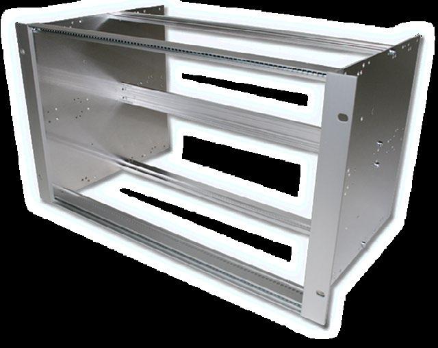
U-HANDLE OF ALUMINUM
■ Aluminum, anodized
■ Width: 9 mm
Scope of delivery:
■ 1 aluminum handle
■ 2 countersunk screw torx T20 (M4 x 10)
■ Universal handle
■ White aluminum, wet painted (RAL 9006)
Scope of delivery:
■ 1 aluminum handle
■ 2 countersunk screws torx T20 (M4 x 10)
LINE DRAWING
RECESSED CARD INSTALLATION KIT
■ For recessed mounting of Eurocards (without front panels)
Scope of delivery:
■ 2 internal extrusions
■ 2 tapped strips M2.5
■ Assembly material (8 cylinder head screws with torx T20 (M4 x 10)
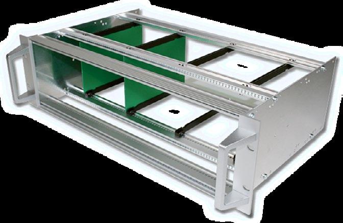
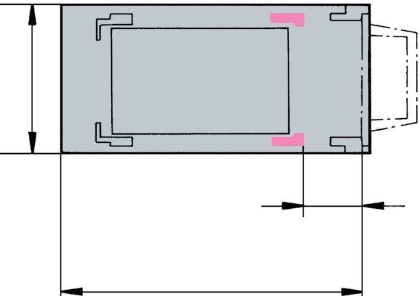
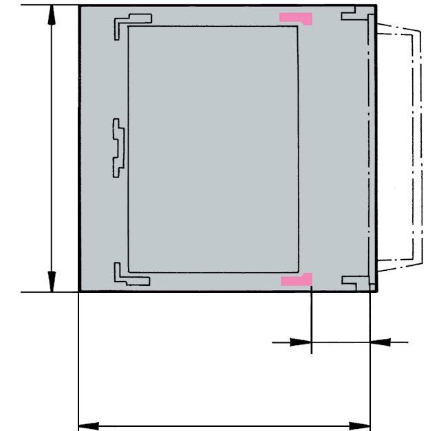
HORIZONTAL
■ For sub division of front
■ Possibility to mount card guides
■ Built on a special extrusion
■ Easy and quick assembly
■ Cost effective solution
■ Delivered in set form
■ Usable width 84 HP
■ Other widths on request
Scope of delivery:
■ 1 piece passivated front sub division extrusion
■ 2
■
FRONT SUB DIVISION HORIZONTAL IEC
■ For sub division of front
■ Without possibility of using card guides
■ Built on a special extrusion
■ Easy and quick assembly
■ Cost effective solution
■ Delivered in set form
■ Usable width 84 HP
■ Other widths on request
Scope of delivery:
■ 1 piece passivated front sub division extrusion
■ 2 pieces tapped strips M2.5
■ 4 pieces cylinder head screws torx T20 (M4 x 10)
EDGE CONNECTOR EXTRUSION
■ Suitable for standard extrusion 66-144
■ Edge connector extrusion without assembly material
8 40.6 1.59 66-145-40
18 91.4 3.59 66-145-41
28 142.2 5.6 66-145-42
42 213.4 8.4 66-145-63
63 320 12.6 66-145-65
81 411.5 16.2 66-145-22
84 426.7 16.8 66-145-52 1350 53.14 66-145-19
Assembly material:
EDGE CONNECTOR EXTRUSION
■ For use with a backplane mounting extrusion 66-193
■ Edge connector extrusion without assembly material
8 40.6 1.59 66-147-40
18 91.4 3.59 66-147-41
28 142.2 5.6 66-147-42
42 213.4 8.4 66-147-63
63 320 12.6 66-147-65
81 411.5 16.2 66-147-22
84 426.7 16.8 66-147-52 1350 53.14 66-147-19
Assembly material:
*electrically conductive
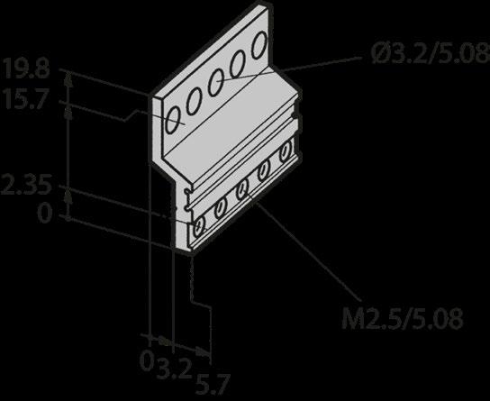
*electrically conductive
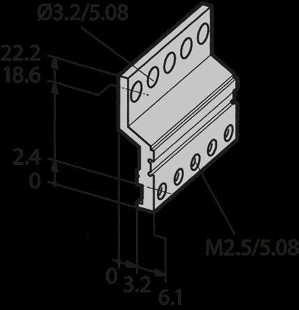
■ Single and double Eurocards (6 U)
Scope of delivery:
■ 1 divider extrusion front
■ 1 divider extrusion rear
■ 2 front extrusions
■ 2 internal extrusions
■ 1 set assembly material (cross recessed)
Front sub division vertical 6 | 3 U:
■ Other versions on request
Tapped strips for front extrusion:
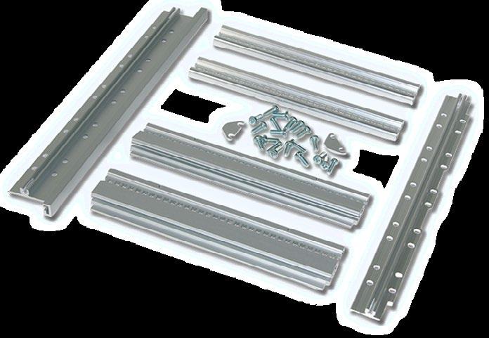
■ Double Eurocards (6 U)
■ Independent of card depth
■ Top and bottom cover plate when no overall fan front panel is used (has to be ordered separately)
Scope of delivery:
■ 4 distance plates (2 in front | 2 rear)
■ 4 front extrusion (2 in front | 2 rear)
■ 1 center extrusion
■ 6 tapped strips M2.5
■ 1 set assembly material (torx)
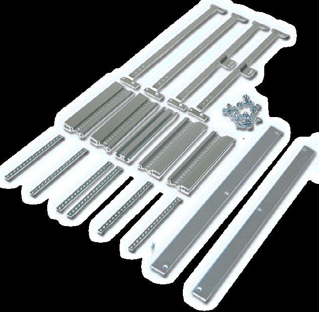
■ 1 mm sheet aluminum, perforated
■ Fastening on longitudinal and internal extrusion
■ Thread in front and internal extrusion available
■ Mechanical protection for the card area
■ Cover plates for card depths 300 and 400 mm on request
Scope of delivery:
■ 1 perforated cover plates

and depths on request

Assembly material:
■ Enables enclosures to be grounded in conformance with EN / VDE / NIV
Scope of delivery:
■ 1 threaded bolt M4 x 8
■ 1 sealing ring
■ 1 lock washer
■ 1 hexagonal nut M4
set according to EN / VDE / SEV 63-127
Further general accessories can be found in the brochure ''General accessories'' or on request.
MAIN FEATURES
Magic- and Spirit-Kit 11 are EMC shielded subracks for IEC or IEEE applications. Both subracks impress with their simple and cost-effective structure with excellent EMC capability. Sheet steel side walls ensure extremely fast assembly and EMC protection without seals.
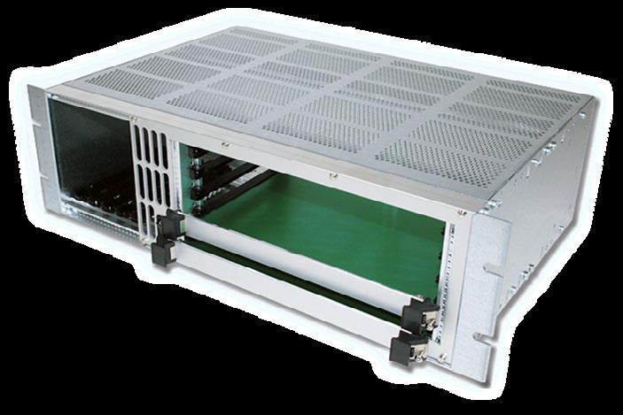
› Advanced EMC shielding without gaskets (standard)
› Internal adaption parts freely accessible
› Quick assembly
› Sheet steel, pre-galvanised
› Vibration-proof
› Dimensions and adaptations according to IEC 60297
› Suitable for IEC 60297 (Magic-Kit 11) or IEEE 1101.10 (Spirit-Kit 11)
PRODUCT VARIETY
› Magic-Kit 11 according to IEC 60297
› Spirit-Kit 11 according to IEEE 1101.10
› Numerous accessories
› Vertical and horizontal card mounting
POSSIBLE CUSTOMIZATIONS
■ Several depths
■ 3 or 6 U
■ Individual interior design
TYPICAL APPLICATIONS
■ Electronics in a protected EMC environment
■ Application in invisible areas (cabinet installation)
■ Cost sensitive projects
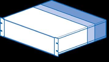
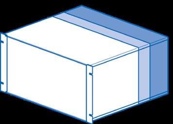
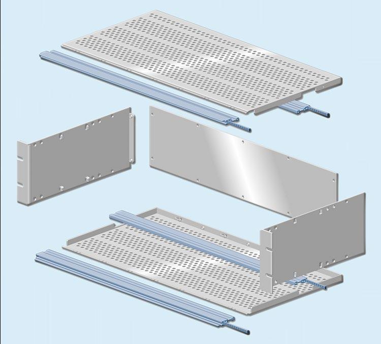
EXECUTIONS
MAGIC-KIT 11
Front extrusions according to IEC 60297 specifications
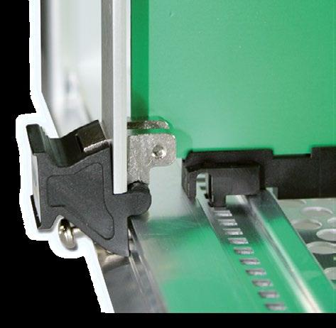
ASSEMBLY INSTRUCTIONS
QUICK ASSEMBLY
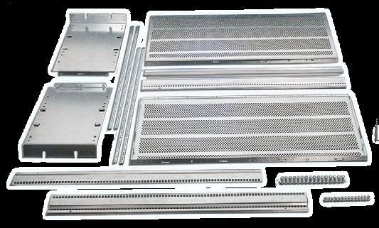
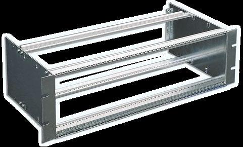
SPIRIT-KIT 11
Front extrusions according to IEEE 1101.10 and CompactPCI specifications, designed for plug-in units with high forces
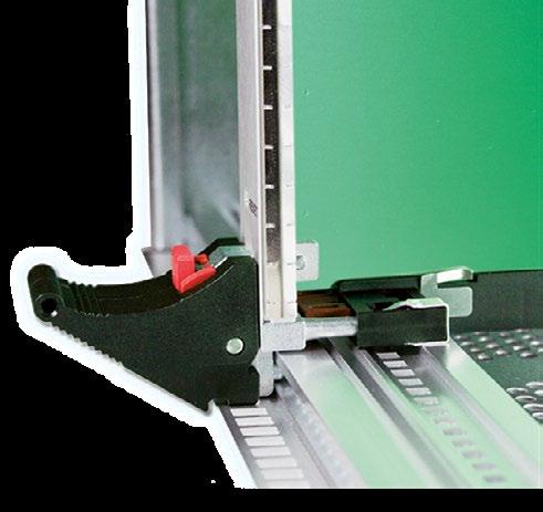
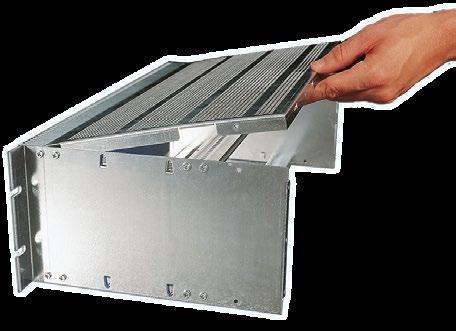
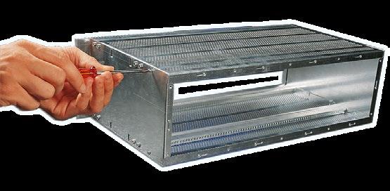
Electromagnetic comptability is the ability of a system to operate in the intended environment without causing or suffering unacceptable degradation of performance due to unintentinal electromagnetic radiation or response. The EMC characterstics of a system therefore consist of an appropriate immunity from interference (noise immunity) and a limited emission of interference (noise emission).
Elma’s EMC concept describes three levels of electromagnetic shielding performance (performance level). The attenuation levels will simplify the selection of subracks for the user. Test setup: The first measurement E1 is without the enclosure. The next measurement E2 is made with the transmitting antenna installed inside the enclosure. The difference between the received signal without and with the enclosure represents the shielding effectiveness in dB.
1
2
3
The standard configuration will already provide an advanced EMC level. Upon request, a superior level can be worked out in cooperation with the Elma engineering.
TYPICAL SHIELDING EFFECTIVENESS
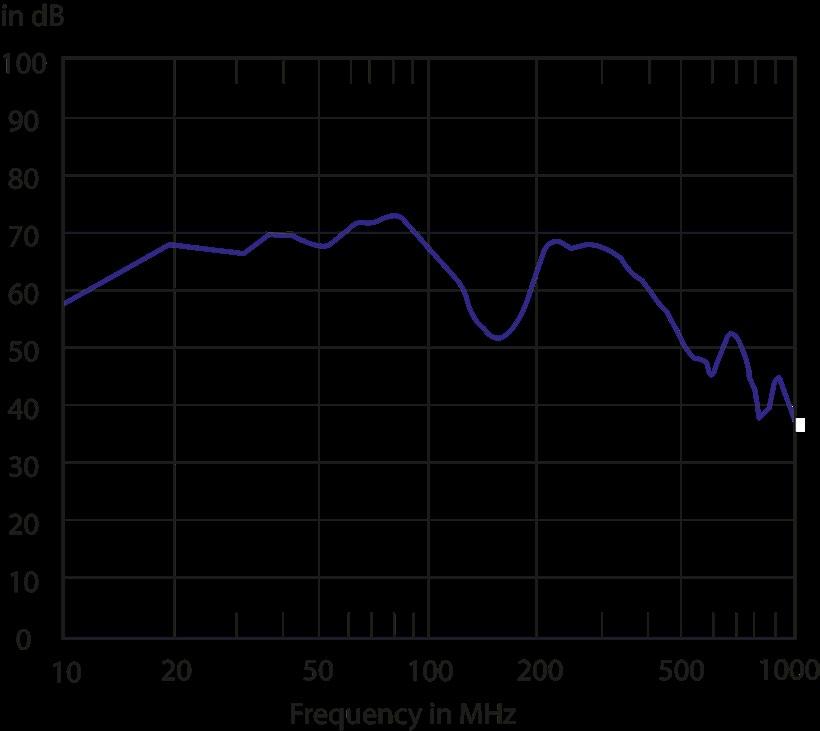
By means of standard snap-fit and screw connections suitable for demanding applications.
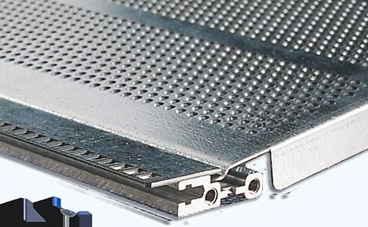
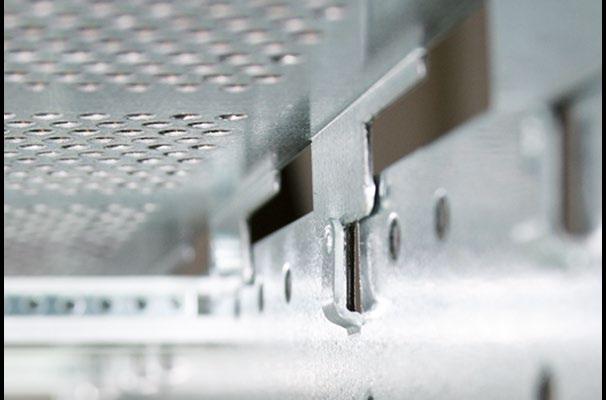
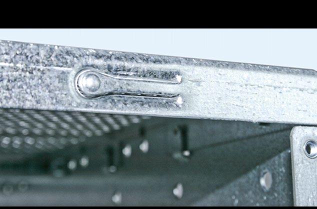
BASIC
■ EMC level: Advanced (standard)
■ Top and bottom covers fully perforated
■ Aluminium extrusions, electrically conductive
■ Side plates, top and bottom covers of pre-galvanised sheet steel
Scope of delivery:
■ 2 side panels
■ 2 front extrusions
■ 2 internal extrusions
■ 4 tapped strips (6 pieces for 6 U)
■ 2 insulating strips (for backplane, insulated mounting only);
■ 4 pieces for 6 U
■ 2 top / bottom covers, perforated
■ Assembly material
■ EMC gasket for front / side
■ 1 double extrusion (6 U only)
Rear panel has to be ordered separately
Rear Panel:
■ Galvanized sheet steel
■ Scope of delivery: 1 rear panel (assembly material included in case)
3
6 U Rear panel
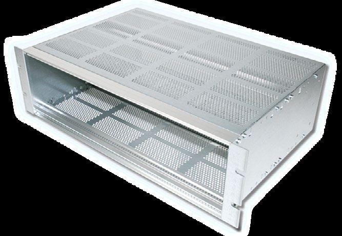
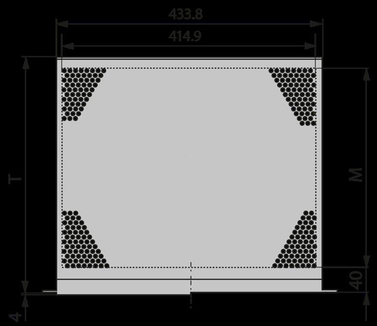
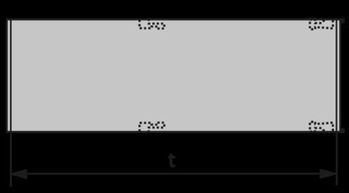
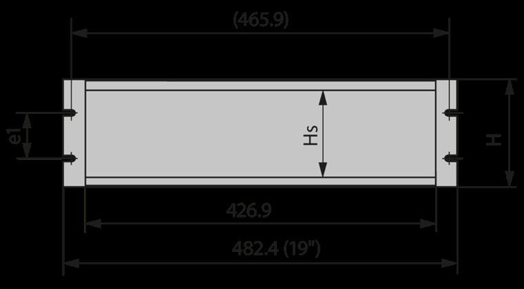
ADAPTION KIT FOR RECESSED CARD INSTALLATION
Range of application:
■ Recessed mounting of single / double eurocards depth 160 to 220 mm
■ Without individual front panels
Scope of delivery:
■ 2 internal extrusions
■ 2 tapped strips
■ 1 set assembly materiall
mounting of single / double eurocards without front panels
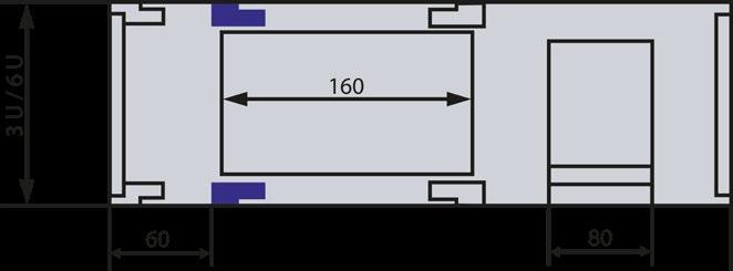
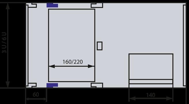
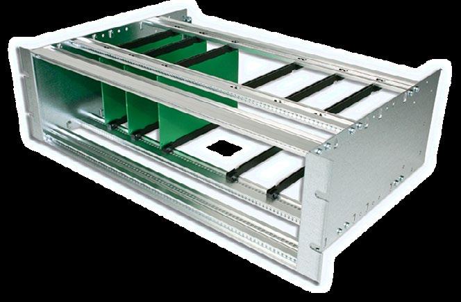
EDGE CONNECTOR EXTRUSION 66-147
■ For use with extrusions for backplanes 66-193
Scope of delivery:
■ 1 aluminium extrusion, clear passivated (conductive)
Assembly material
■ Allows both single and double eurocards to be mounted together in a 6 U Magic- and Spirit-Kit 11
Scope of delivery:
■ 1 divider extrusion front
■ 1 divider extrusion rear
■ 2 front extrusions
■ 2 internal extrusions
Tapped strips for front extrusion
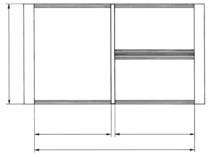
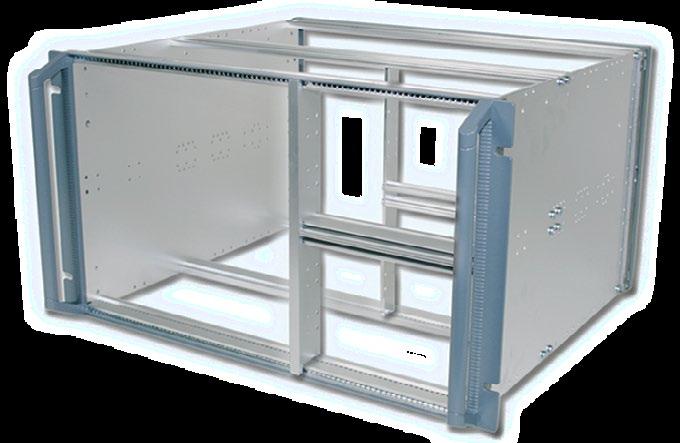
■ For double eurocards (6 U)
■ Independent of card depth
Scope of delivery:
■ 4 distance plates (2 front / 2 rear)
■ 4 length extrusions (2 front / 2 rear)
■ 1 centre extrusion
■ 6 tapped strips M2.5
■ 1 set assembly material
■ Top and bottom cover plate, when no overall fan front panel is used (have to be ordered separately)
■ 1 assembly material * Assembly material for cover plate see below
Front panel screws:
■ For cover panel
■ Delivery scope: Set of 10 screws (incl. screw retainer)
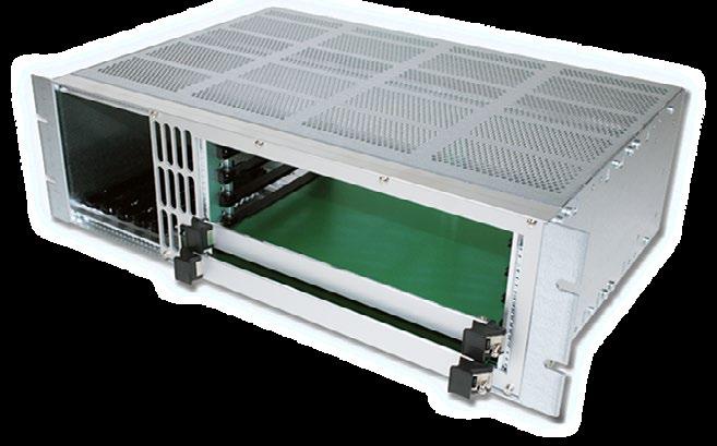
■ For mounting non-standard modules and components
■ Mounting chassis is fixed directly to the side panel
Scope of delivery:
■ 1 mounting chassis
■ 1 set of assembly material (4 earthing nuts, 4 screws M4 x 6)
Mounting chassis depth 80 mm:
Mounting chassis depth 140 mm:
■ Fixing on extrusion (for front panels)
■ Self-adhesive
Scope of delivery:
■ 2 contact strips
■ Enables enclosures to be earthed in conformance with EN / VDE / SEV
Scope of delivery:
■ 1 press-in threaded bolt M4
■ 2 serrated lock washers
■ 2 nuts M4
■ 1 clamp
■ 1 protective conductor symbol
General accessories can be found in the brochure ''General accessories'' or on request.
The Systemkit 12K is a high quality subrack system that high flexibility with wide functionality united. Completely made of aluminum, it already offers significant advantages in a standard version such as...
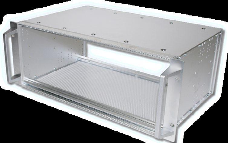
› Choice between VME, VME64x or cPCI application
› Possibility for rear I/O mounting
› EMC level: Basic (already in the basic version without additional EMC parts)
› RoHS compliant
› Different heights and depths available
› Accessory sets for individual expansion
› Customizations on request
› Additional dimensions for special card depths
› Combination of rear I/O and recessed card mounting
› Horizontal and vertical divisions
› Increased EMC protection with optional gaskets
› Special equipment on request
› Various sizes and colors
› Individual interior design
Executions
SIZES
■ 3 to 9 U (height units)
■ 84 HP
■ Depth: 289 to 500 mm
COLORS
■ Clear passivated
■ Colors on request
The Systemkit 12K was tested according to the following norms:
■ Vibration
■ Shock
■ Dry heat
EN60068-2-6
EN60068-2-27
EN60068-2-2
■ Damp heat, cyclic
EN60068-2-30
■ Cold EN60068-2-1
■ Salt spray test DIN50021
Electromagnetic comptability is the ability of a system to operate in the intended environment without causing or suffering unacceptable degradation of performance due to unintentinal electromagnetic radiation or response. The EMC characterstics of a system therefore consist of an appropriate immunity from interference (noise immunity) and a limited emission of interference (noise emission). Elma’s EMC concept describes three levels of electromagnetic shielding performance (performance level). The attenuation levels will simplify the selection of sub racks for the user. Test setup: The first measurement E1 is without the enclosure. The next measurement E2 is made with the transmitting antenna installed inside the enclosure. The difference between the received signal without and with the enclosure represents the shielding effectiveness in dB.
The standard configuration will provide you with a basic EMC level. If you require an advanced or superior EMC level for your system, you need to order additional EMC parts.
CPCI (IEEE1101.10 / IEEE101.11) STANDARD CONFIGURATIONS**
VME (IEEE1101.10 / IEEE101.11) STANDARD CONFIGURATIONS**
VME (IEC60297) STANDARD CONFIGURATIONS**
Scope of delivery:
■ 2 side walls
■ 4 front extrusions
■ 4 tapped strips M2.5
■ 1 set assembly material (16 cylinder head screw torx T20 (M4 x 10))
cPCI application (IEEE1101.10 | IEEE1101.11):
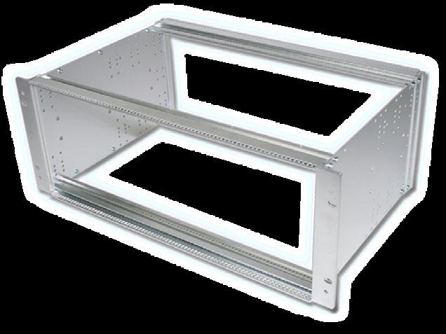
VME64x application (IEEE1101.10 | IEEE1101.11)
VME application (IEC60297)
INTERNAL EXTRUSIONS INTERNAL EXTRUSIONS FOR INSULATAD BACKPLANE MOUNTING
Scope of delivery:
■ 2 internal extrusions
■ 2 tapped strips M2.5
■ 2 insulating strips
■ Assembly material (8 cylinder head screw torx T20 (M4 x 10))
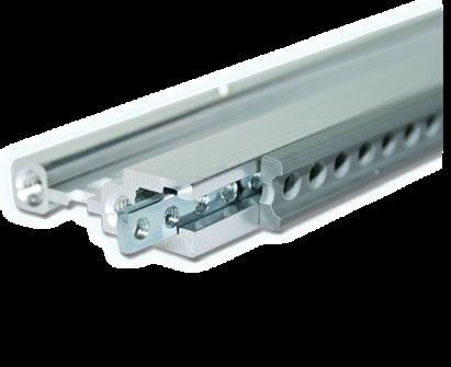

INTERNAL EXTRUSIONS FOR CONDUCTIVE BACKPLANE ASSEMBLY
Scope of delivery:
■ 2 internal extrusions
■ 2 tapped strips M2.5
■ Assembly material (8 cylinder head screws torx T20 (M4 x 10))
mounting of backplane
DOUBLE EXTRUSIONS FOR INSULATED BACKPLANE MOUNTING
■ For 6 U cards only
■ Stiffener for VME monolithic backplanes
■ Fixing for J1 and J2 backplanes
Scope of delivery:
■ 1 double extrusion
■ 2 tapped strips
■ 2 insulating strips
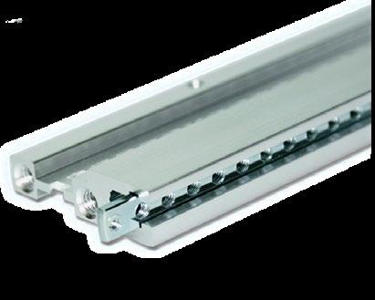

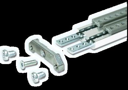
■ Assembly material (8 x torx T20 (M4 x 6) | 2 x torx T20 (M3 x 10) | 2 x adapter)
1 set double extrusion for insulated backplane mounting 12K508
DOUBLE EXTRUSIONS FOR CONDUCTIVE BACKPLANE ASSEMBLY
■ For 6 U cards only
■ Stiffener for VME monolithic backplanes
■ Fixing for J1 and J2 backplanes
Scope of delivery:
■ 1 double extrusion
■ 2 tapped strips
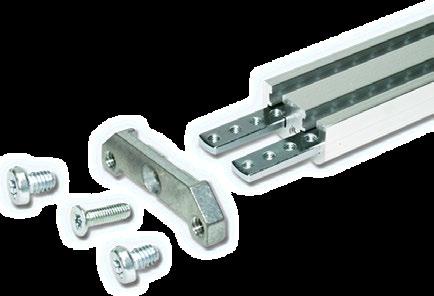
■ Assembly material (8 x torx T20 (M4 x 6) | 2 x torx T20 (M3 x 10) | 2 x adapter)
1 set double extrusion for non-insulated backplane mounting 12K509
HEIGHT EXTRUSIONS FOR 19'' VERSION
■ Not suitable for telescopic rail mounting
■ Handles and EMC gaskets see below
Scope of delivery:
■ 2 19'' height extrusions (front)
■ 2 height extrusions (rear)
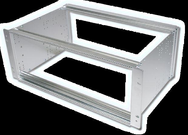
Socpe of delivery:
■ 1 handle for height extrusions
■ Assembly material
■ Per subrack 2 handles have to be ordered
Scope of delivery:
■ 1 handle for height extrusions
■ Assembly material
■ Per subrack 2 handles have to be ordered
HEIGHT EXTRUSIONS FOR 19'' VERSION (FROM TELESCOPIC RAILS)
HEIGHT EXTRUSIONS FOR ASSEMBLY OF TELESCOPIC RAILS
Scope of delivery:
■ 2 19'' height extrusions (front)
■ 2 height extrusions (rear)
■ 2 die cast aluminum handles
■ Assembly material (4 countersunk screw torx T20 (M4 x 10))
3
TELESCOPIC RAILS SET (LOAD CAPACITY UP TO 60 KG / PAIR)
Scope of delivery:
■ 2 telescopic rails
■ Mounting bracket and assembly material for mounting into cabinet and on module
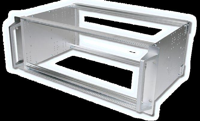
REDUCTION SET
REDUCTION KIT 1/3 U + 2/3 U FOR FRONT MOUNTING | SOLID
■ Material: Aluminum 1.5 mm, conductive, depth independent (to be used in conjunction with the bottom / top panel)
■ For 160 mm card depth, 4 U enclosure (Eurocards) | 7 U enclosure (double Eurocards)
Scope of delivery:
■ 1 adapter top (1/3 U), 1 adapter bottom (2/3 U) incl. fan plate
■ 1 set assembly material (6 x torx T10 (M3 x 8) | 4 x torx T20 (M4 x 10)) Other heights on request
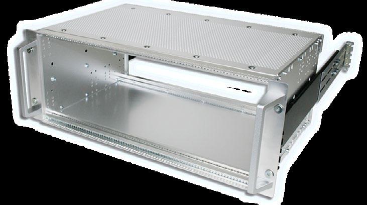
Rugged telescopic rails, load capacity up to 90 kg / pair on request
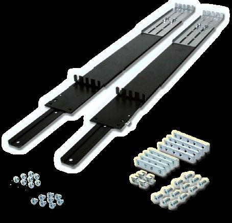
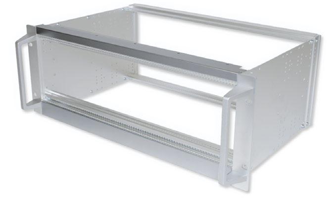
REDUCTION SET
ADDITIONAL FAN PLATE
Scope delivery for additional fan plate (for easy access and maintenance of the fans):
■ 1 fan plate
■ 8 milled edge screw torx T10 (M3 x 5)
REDUCTION KIT 1/3 U + 2/3 U FOR 60 MM RECESSED MOUNTING
■ Material: Aluminum 1.5 mm, conductive, depth independent (to be used in conjunction with the bottom / top panel)
■ For 60 mm recessed mounting, 160 mm card depth, for 4 U enclosure (Eurocards) | for 7 U enclosure (double Eurocards)
Scope of delivery:
■ 1 adapter top (1/3 U), 1 adapter bottom (2/3 U) incl. fan plate
■ 1 set assembly material (6 x torx T10 (M3 x 8) | 4 x torx T20 (M4 x 10))
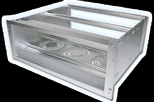
Scope of delivery for additional fan plate (for easy access and maintenance of the fans):
■ 1 fan plate
■ 8 milled edge screw torx T10 (M3 x 5)
REDUCTION KIT 1/3 U + 2/3 U FOR FRONT MOUNTING
■ Material: Aluminum 1.5 mm, conductive, depth independent (to be used in conjunction with the bottom / top panel)
■ For 4 U enclosure (Eurocards) | for 7 U enclosure (double Eurocards)
Scope of delivery:
■ 1 adapter (2/3 U)
■ No assembly material needed
■ Per subrack 2 pieces (4 pieces with rear I/O) are requiered
*only bottom part (2/3 U) is perforated perforated version on request
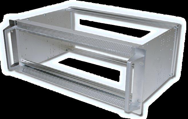
REDUCTION SET
REDUCTION KIT 1/2 U + 1/2 U FOR 60 MM RECESSED MOUNTING
■ Material: Aluminum 1.5 mm, conductive, depth independant (to be used in conjunction with the bottom / top panel)
■ For 4 U enclosure (Eurocards) | for 7 U enclosure (double Eurocards)
Scope of delivery:
■ 1 adapter bottom (1/2 U)
■ 1 set assembly material (2 cylinder head screw torx T20 (M4 x 10))
■ Per subrack 2 pieces have to be used
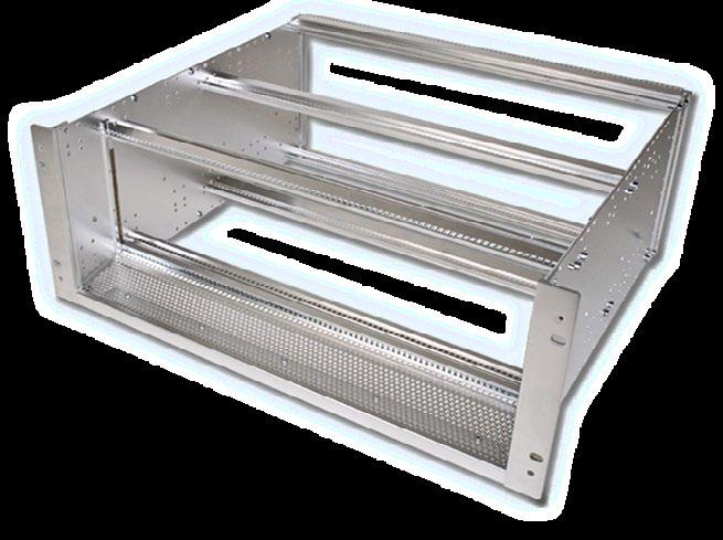
■ Note: The depth independent ½ U adapter are to be used in conjunction with the bottom / top panel
perforated version on request
BOTTOM / TOP PANEL SOLID
■ Material: Aluminum 1.5 mm, conductive
■ EMC level: Basic
Scope of delivery:
■ 1 bottom / top panel solid
■ 1 set assembly material (18 cylinder head screw torx T10 (M3 x 6))
PERFORATED
■ Material: Aluminum 1.5 mm, conductive
■ EMC level: Basic
Scope of delivery:
■ 1 bottom / top perforated
■ 1 set assembly material (18 cylinder head screw torx T10 (M3 x 6))
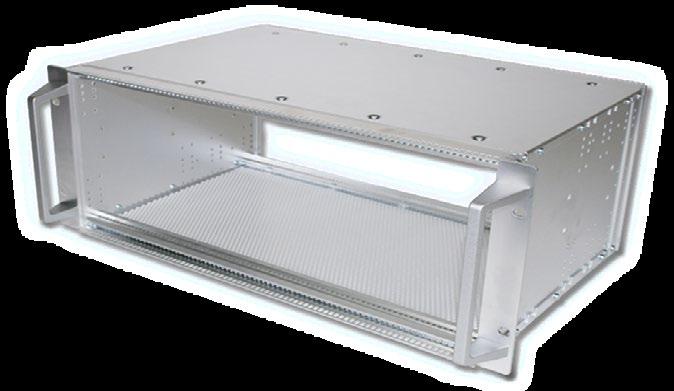
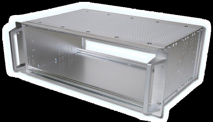
■ For 80 mm card depth (cPCI) | 160 mm card depth (VME and VME64x)
Scope of delivery:
■ 2 internal extrusion for rear I/O card mounting
■ Assembly material (4 cylinder head screw torx T20 (M4 x 10))
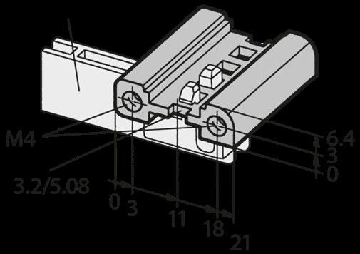
EMC FRONT SUB DIVISION HORIZONTAL FOR 84 HP SUBRACKS
■ EMC level: Advanced
■ Fastening: Card guides be applied on upper and lower card cage side
Scope of delivery:
■ 2 front extrusion
■ 1 EMC gasket
■ 3 spacers
■ 1 set assembly material (8 cylinder head screw torx T20 (M4 x 10) | 6 cylinder head screw torx T10 (M3 x 6))
■ 2 tapped strips M2.5
EMC FRONT SUB DIVISION HORIZONTAL IEC FOR CARD GUIDES
■ For sub division of front and rear
■ Card guide can be mounted on one side
■ EMC level: Superior
■ Only one special extrusion needed | easy and quick assembly | delivered in set
■ Usable width: 84 HP
■ Other sizes on request
Scope of delivery:
■ 1 front double extrusion special, clear passivated
■ 2 tapped strips M2.5
■ 4 cylinder head screw torx T20 (M4 x 10)
EMC FRONT SUB DIVISION HORIZONTAL IEC
■ For sub division of front or rear
■ Without possibility of mounting card guides
■ EMC level: Superior
■ Only one special extrusion needed | easy and quick assembly | delivered in set
■ Usable width: 84 HP
■ Other sizes on request
Scope of delivery:
■ 1 front double extrusion IEC special, clear passivated
■ 2 tapped strips M2.5
■ 4 cylinder head screw torx T20 (M4 x 10)
EMC FRONT SUB DIVISION HORIZONTAL IEEE FOR CARD GUIDES
■ EMC level: Superior
■ Only one special extrusion needed
■ Card guides can be mounted on one side
■ Easy and quick assembly
■ Usable width: 84 HP
■ Other sizes on request
Scope of delivery:
■ 1 front double extrusion IEEE special, clear passivated
■ 2 tapped strips M2.5
■ 4 cylinder head screw torx T20 (M4 x 10)
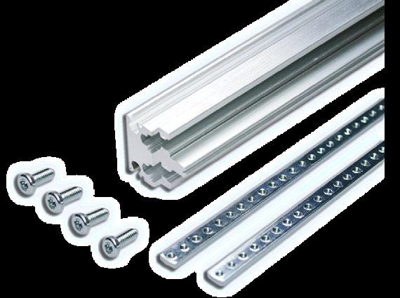
■ Stainless steel
■ Snapped-in on the extrusion
Scope of delivery:
■ 2 HF spring 84 HP
FRONT SUB DIVISION
EMC CONTACT STRIPS
■ BeCu galvanized
■ For front panels, fixing on extrusion
■ Self-adhesive
Scope of delivery:
■ 2 EMC contact strips
FRONT SUB DIVISION
FRONT SUB DIVISION VERTICAL FOR 6 U SYSTEM | 6 U ASSEMBLY
■ For the partial sub division of 6 U in 2 x 3 U
Scope of delivery:
■ 1 divider extrusion front
■ 1 divider extrusion rear
■ 2 front extrusions
■ 2 internal extrusions
■ Assembly material (16 cylinder head screw torx T20 (M4 x 10) | 4 cylinder head screw torx T10 (M3 x 12))
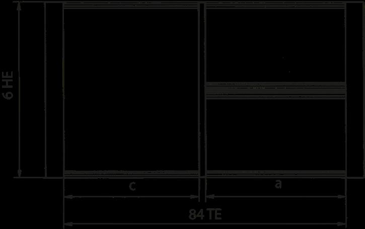
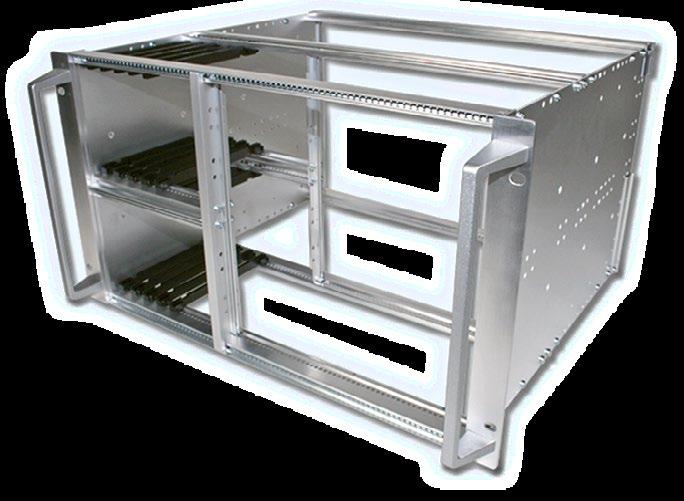
HORIZONTAL INSTALLATION KIT FOR DOUBLE EUROCARDS
■ Suitable for 6 U and VME
■ Card depth independent
■ Mounting width: 52 HP
Scope of delivery:
■ 1 set incl. assembly material
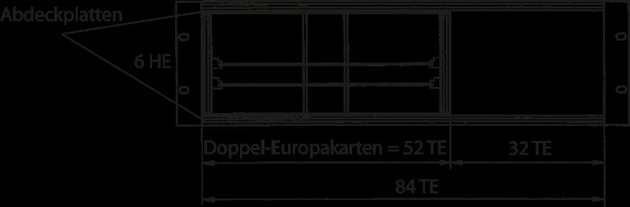
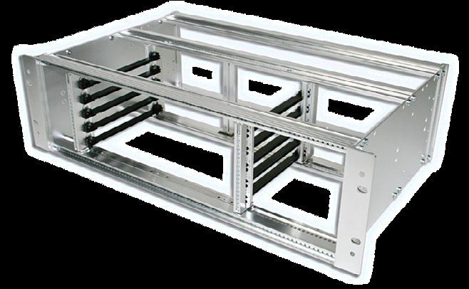
Front panel screws:
■ Set with 10 screws, with screw retainer
Screw torx T8 (M2.5 x 11.3) with plastic screw retainer
with plastic screw retainer
HORIZONTAL EMC INSTALLATION KIT FOR DOUBLE EUROCARDS
■ Suitable for 6 U
■ Card depth 160 mm
■ Backplane mounting
■ The fan module must be installed on the right side (fan not included in the scope of delivery)
Scope of delivery:
■ Card mounting kit incl. fan tray and connector (incl. assembly material)
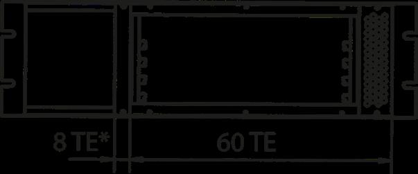
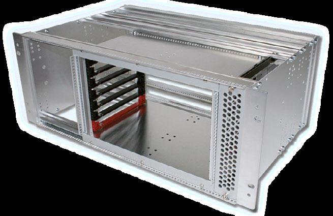
General accessories can be found in the brochure ''General accessories'' or on request.
HORIZONTAL INSTALLATION KITS
HORIZONTAL EMC INSTALLATION KIT FOR REAR I/O EUROCARDS
■ Suitable for rear I/O double Eurocards (6 U)
■ Card depth 80 mm (cPCI) | 160 mm (VME and VME64x)
■ Backplane mounting
Scope of delivery:
■ 1 set incl. assembly material and cover on side
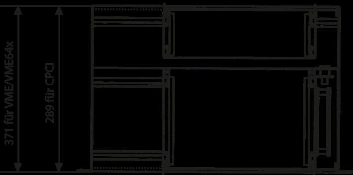
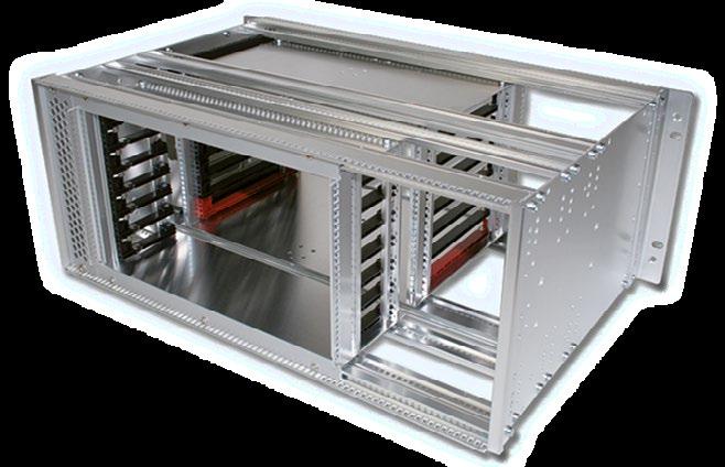
EMC SET FOR BOTTOM / TOP PANEL
DEPTH | EMC LEVEL: ADVANCED
Scope of delivery:
■ 4 EMC gasket for depth
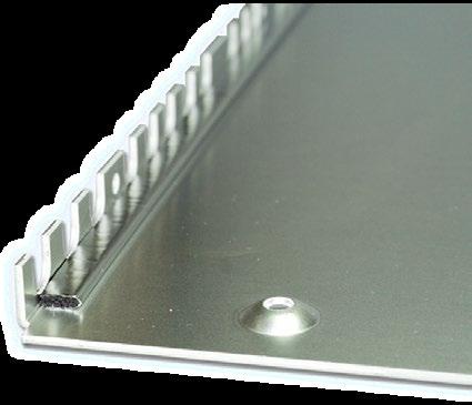
WIDTH | EMC LEVEL: ADVANCED
Scope of delivery:
■ 4 EMC gasket for width
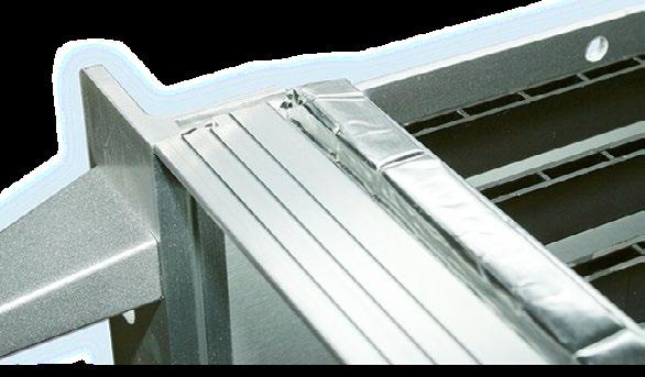
4 gaskets, 6 x 7 mm x 84 HP, use without height
2 gaskets, 6 x 7 mm x 84 HP | 2 gaskets 4 x 7 mm x 84 HP, when using only one height reduction kit at front or rear
EXTRUSION FOR RECESSED EMC MOUNTING | EMC LEVEL: BASIC
■ Interior fitting: Extrusion bolts with side walls
■ Application: Recessed installation of front panel
■ Can be used in conjunction with EMC sets and gasket to achieve advanced EMC level
Scope of delivery:
■ 2 EMC extrusions
■ 8 cylinder head screw torx T8 (M2.5 x 4)
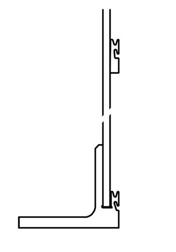
Dichtung nach hinten
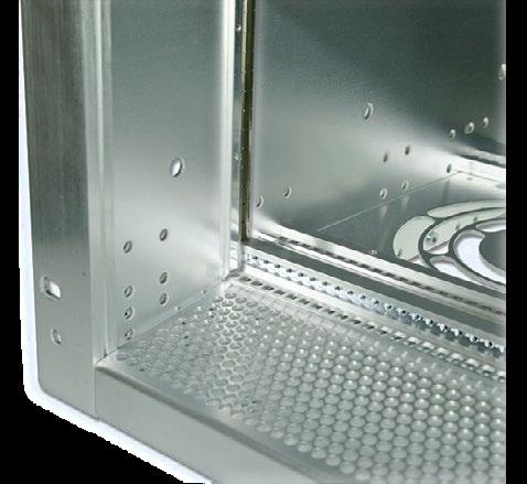
EMC GASKET FOR HEIGHT EXTRUSIONS | FRONT PANEL | EMC LEVEL: ADVANCED
■ Front or recessed mounting
■ 1 front panel per slots
■ Application: Height extrusions front / rear, front panel
■ Gasket is installed onto the extrusion
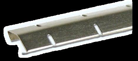
■ When using an EMC gasket in connection with a card, the gasket must be selected in the card depth
■ When a height reduction is used, choose height between reductions
■ Can be used in conjunction with EMC sets to achieve advanced EMC level
EMC CONTACT STRIPS | EMC LEVEL: ADVANCED
■ For front panels, fixing on extrusion
■ Self-adhesive
Scope of delivery:
■ 2 contact strips
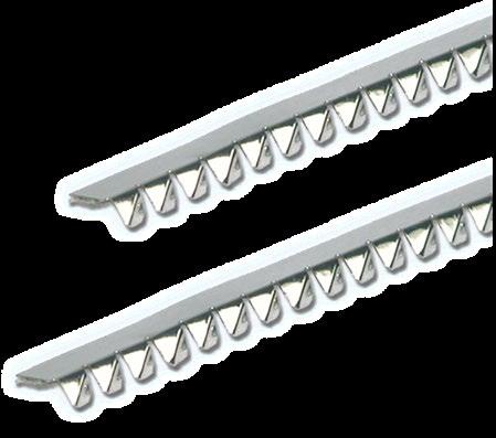
REINFORCED:
■ Aluminum 2 mm
Scope of delivery:
■ Mounting chassis 85 HP (431.8 mm)
■ Assembly material (4 earthing nuts M4, 4 cylinder head screw torx T20 (M4 x 6))
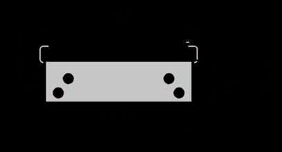
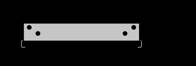
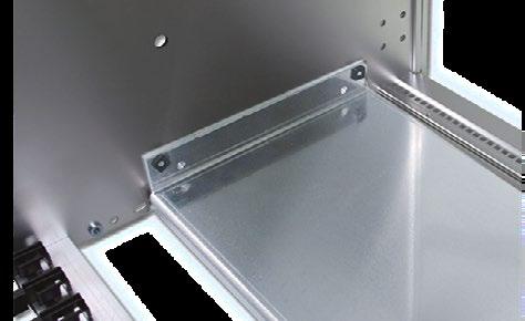
■ Mounting non-standard modules and components
■ Mounting chassis is fixed directly on the side panel
■ Aluminum 2 mm, raw
Scope of delivery:
■ 1 mounting chassis
Assembly material:
■ 4 cylinder head screw torx T20 (M4 x 6) and 4 earthing nut M4
■ Mounting chassis depth 207 mm can be mounted with 4 screws (317 mm with 8 screws, 419 mm with 10 screws)
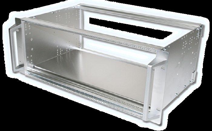
EMC FLAT FRONT PANELS
■ Aluminum 2.5 mm (conductive)
■ Closes the front or rear of the subrack with very high shielding effectiveness
■ Contact between the flat front panel and the enclosure is made via EMC gaskets
FLAT FRONT PANEL EMC LEVEL ADVANCED
Scope of delivery:
■ 1 EMC flat front panel
■ 1 contact angle incl. screws (4 + 6 U version only)
■ 1 EMC gasket for contact angle (4 + 6 U version only)
Front panel screws:
■ Front panel width 42 HP = 4 screws
■ Front panel width 63 HP = 6 screws
■ Front panel width 84 HP = 8 screws
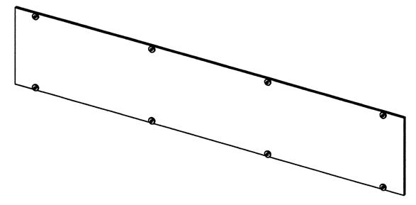
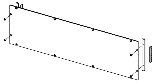
FLAT FRONT PANEL EMC LEVEL SUPERIOR
Scope of delivery:
■ EMC flat front panel
■ Contact angle, incl. screws
■ EMC gasket for contact angle and front extrusion / front panel
Front panel screws:
■ Front panel width 42 HP = 4 screws
■ Front panel width 63 HP = 6 screws
■ Front panel width 84 HP = 8 screws
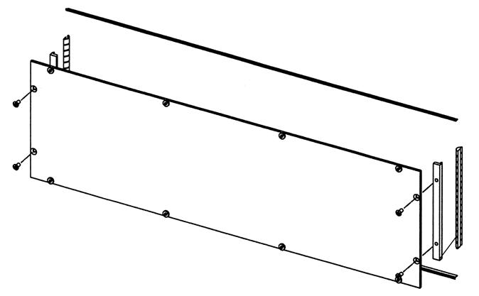
FRONT PANEL
PERFORATED EMC FRONT PANEL
■ Front anodized | rear conductive
■ EMC level: Advanced
■ Width: 84 HP
Scope of delivery:
■ 1 perforated flat front panel
Front panel screws:
EMC FILLER PANEL WITHOUT EMC GASKET
■ Front panel standard, solid
■ Front clear anodized | rear conductive
■ EMC level: Basic
Front panel screws:
■ Front panel width: Up to 9 HP = 2 screws | ≥ 10


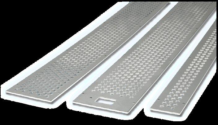
1
SPACER FOR EMC FRONT PANEL FLAT
Scope of delivery:
■ 1 spacer incl. gasket
■ 2 sheet metal screw torx T10 (2.9 x 6.5)
3
4
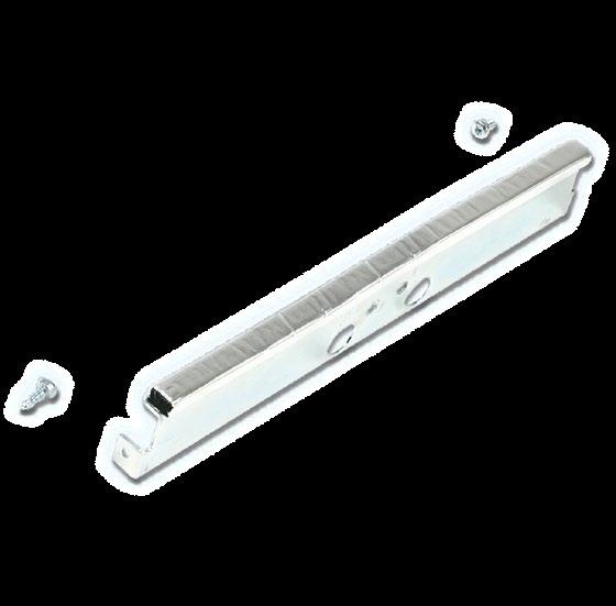
■ For subracks and enclosures, solid
■ Aluminum 2.5 mm, clear anodized (non-conductive)
Scope of delivery:
■ 1 flat front panel
2
3
FRONT EXTRUSION VME
■ Systemkit 12K front
■ Accept 2 x 6 mm tapped strips
Scope of delivery:
■ 1 front extrusion without assembly material
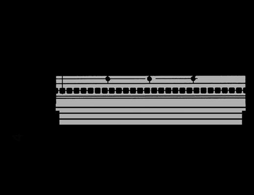
FRONT EXTRUSION CPCI | VME64X
■ Front division profile according to IEEE standard
■ Accept 2 x 6 mm tapped strips
Scope of delivery:
■ 1 front extrusion without assembly material
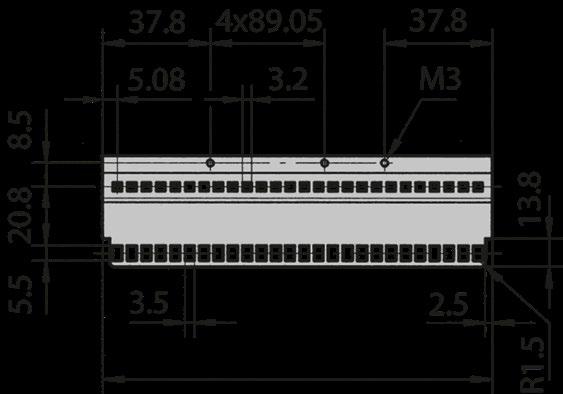
66-193 FOR INSULATED BACKPLANE MOUNTING
■ For mounting backplanes in subracks
■ Accept 1.8 x 5 mm tapped strips
Scope of delivery:
■ 1 internal extrusion without assembly material
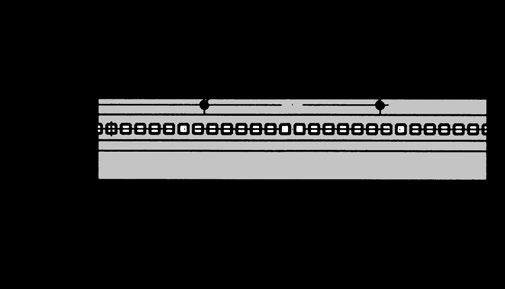
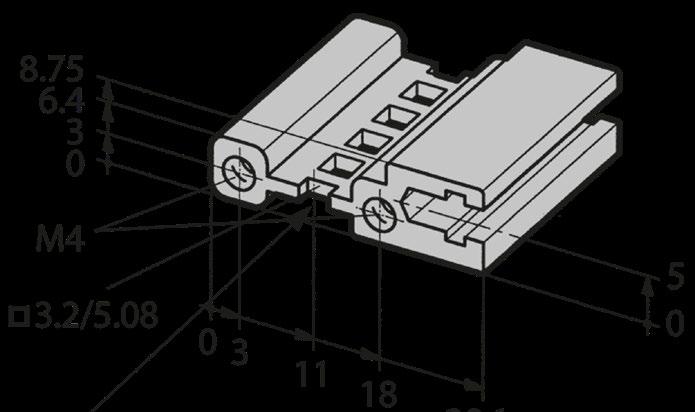
EXTRUSION 66-194 FOR CONDUCTIVE BACKPLANE MOUNTING
■ For mounting backplanes without an insulating strip
■ Accept 1.8 x 5 mm tapped strips
Scope of delivery:
■ 1 internal extrusion without assembly material
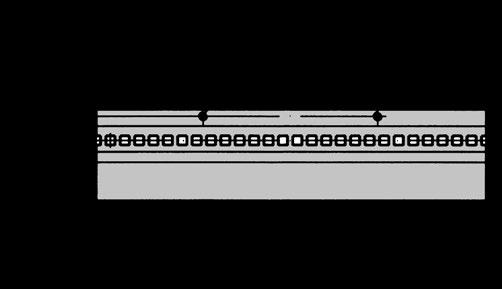
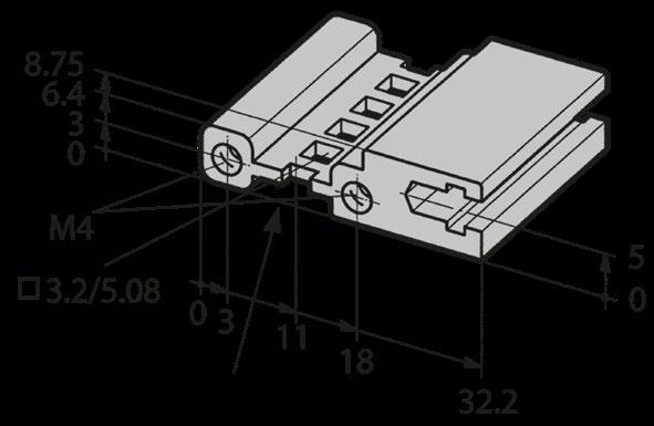
INTERNAL EXTRUSION 66-138 FOR CARD GUIDES
■ For mounting card guides from rear I/O
■ Tapped strip not required
Scope of delivery:
■ 1 internal extrusion without assembly material
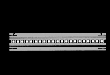

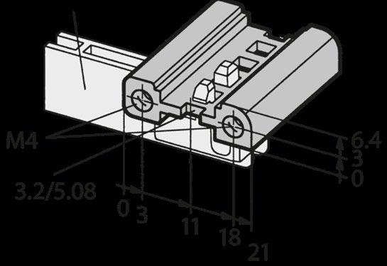
DOUBLE EXTRUSION 66-192 FOR INSULATED BACKPLANE MOUNTING
■ For mounting backplanes, matches to 66-193, 66-288
■ For use with insulating strips
■ Accept 2 x 6 mm tapped strips
Scope of delivery:
■ 1 extrusion without assembly material
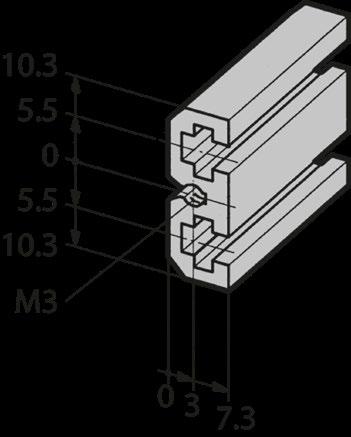
DOUBLE EXTRUSION 66-195 WITHOUT USE OF THE INSULATING STRIPS
■ For mounting backplanes without insulating strips
■ Matches to 66-194, 66-289, 66-290
■ Accept 2 x 6 mm tapped strips
Scope of delivery:
■ 1 extrusion without assembly material
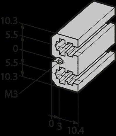
INTERNAL EXTRUSIONS
EDGE CONNECTOR EXTRUSION 66-147
■ For use with extrusions for backplanes 66-193
Scope of delivery:
■ 1 edge connector extrusion without assembly material
8 40.6 1.59 66-147-40
91.4 3.59 66-147-41 28 142.2 5.6 66-147-42 42 213.4 8.4 66-147-63
320 12.6 66-147-65
411.5 16.2 66-147-22
426.7 16.8 66-147-52
53.14 66-147-19
M2.5 (for 2 supplementary extrusions) 63-214
INTERNAL EXTRUSIONS
INSULATING STRIPS 66-901
■ Plastic gray
■ In use with extrusions 66-112, 66-192, 66-193, 66-288
Scope of delivery:
■ 1 insulating strip without assembly material
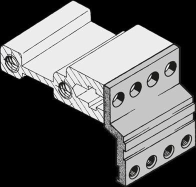
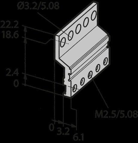
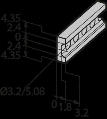
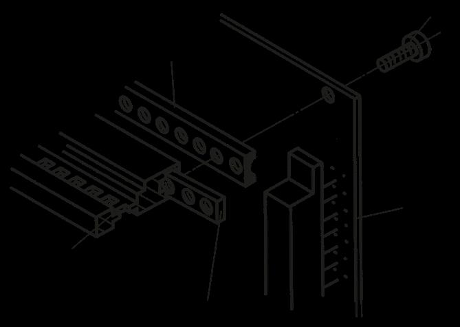
HEIGHT EXTRUSIONS
19'' HEIGHT EXTRUSIONS 66-275
■ For standard side wall 2 mm
■ Shape to direct mounting of the EMC gasket 81-062-XX
Scope of delivery:
■ 1 height extrusions without assembly material
Fixing hole for handle
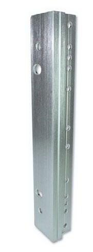
6
9
HEIGHT EXTRUSIONS 66-274
■ For standard side wall 2 mm
■ Shape to direct mounting of the EMC gasket 81-062-XX
Scope of delivery:
■ 1
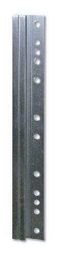
HEIGHT EXTRUSIONS 66-274 WITH CUT-OUT FOR TELESCOPIC RAILS
■ For standard side wall 2 mm with cut-out for telescopic rails
■ Shape to direct mounting of the EMC gasket 81-062-XX
Scope of delivery: ■ 1 height extrusions without assembly material
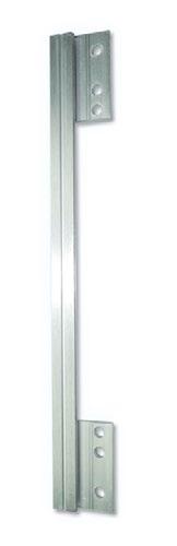
6
Based on the Systemkit 12K, the 12K Rail was specially designed and tested for applications in the railway sector. It thus fulfills all technical requirements according to EN50155.
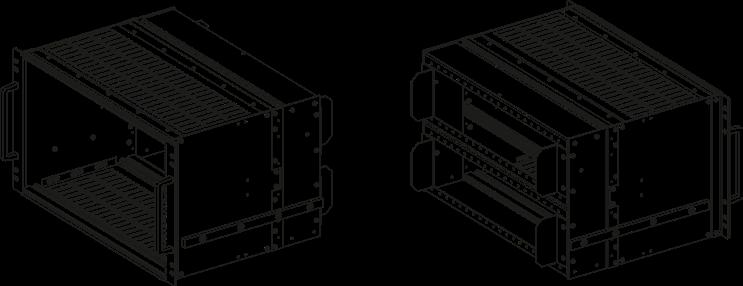
› Tested for SNCF approval
› Tested according to NF F61-005 and NFF 60-002 / NF F67-012
› 3 and 6 U
› 21 T
› 320 mm for card depth 160 and 220 mm
POSSIBLE CUSTOMIZATIONS
› Can be combined with components from the Sytemkit 12K (e.g. EMC protection)
TYPICAL APPLICATIONS
› Rolling stock in railway section
SYSTEMKIT 12K RAIL SNCF | UNSHIELDED
■ SNCF listing No. 1306/058
■ Tested according to NF F61-005 and NFF 60-002 / NF F67-012
■ 3 and 6 U, 21 T, 320 mm for board depth 160 and 220 mm
Delivery of scope:
■ 2 side panels
■ 2 side panels extrusions
■ 2 external guide rails
■ 2 front extrusions
■ 2 internal extrusions
■ 2 height extrusions
■ 2 insulation strips (4 pieces for 6 U)
■ 1 double extrusion (6 U only)
■ 4 tapped strips (6 pieces for 6 U)
■ 1 rear frame (2 pieces for 6 U)
■ 2 protection brackets SNCF (4 pieces for 6 U)
■ 2 handles
■ Assembly material (Torx)
BOTTOM / TOP PANEL AT THE FRONT
■ To shield and protect the sub rack
■ Material: Aluminium 1 mm
■ Incl. EMC contacts
Delivery of scope:
■ 1 bottom / top cover panel
■ Assembly material (10 Torx screws M3 x 6)
Note: 1 T = 4 HP = 20.32 mm,
9 T (36 HP) available on request
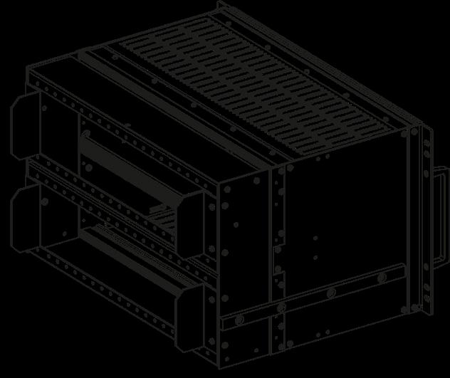
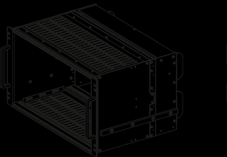
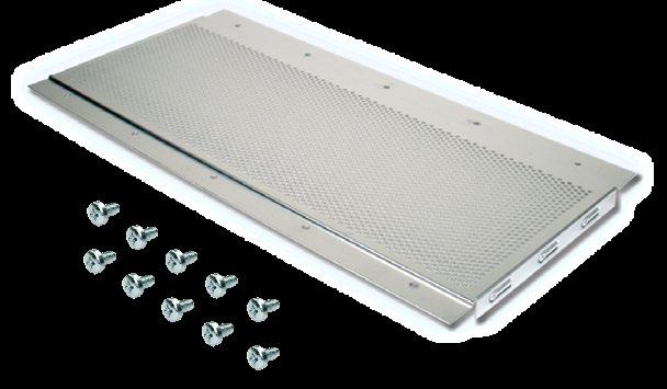

SYSTEMKIT 12K RAIL SNCF | UNSHIELDED
BOTTOM / TOP PANEL AT THE REAR
■ SNCF-specific protection
■ Material: Aluminium 1 mm
Delivery of scope:
■ 1 bottom / top cover panel
■ Assembly material (4
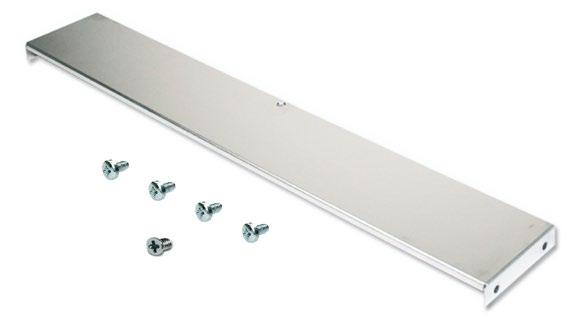
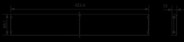
DRAWING SYSTEMKIT 12K RAIL SNCF | 6 HE


SYSTEMKIT 12K RAIL EN50155 | UNSHIELDED
■ Subrack according to IEC and IEEE (CompactPCI) EEE version needs additional bottom / top panels
■ Tested according to EN50155
■ 3 and 6 U, 84 HP, 240 mm for card depth 160 and 220 mm
Delivery of scope:
■ 2 side panels
■ 2 front extrusions
■ 2 internal extrusions
■ 2 height extrusions
■ 1 double extrusion (6 U IEC only)
■ 4 tapped strips (6 pieces assembly material (Torx)
■ 2 handles
■ Assembly material (Torx)

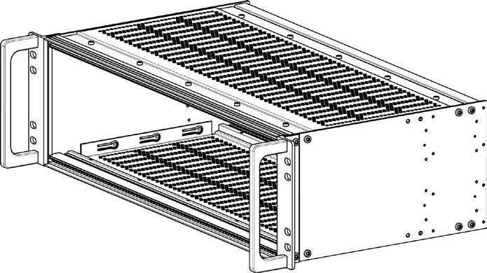
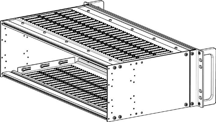
SYSTEMKIT 12K RAIL EN50155 | UNSHIELDED
DRAWING SYSTEMKIT 12K RAIL EN50155 | 3 HE


FOR SYSTEMKIT 12K RAIL SCNF AND EN50155
■ To shield and protect the subrack
■ Material: Aluminium, 1 mm
■ Incl. EMC contacts
Scope of delivery:
■ 1 bottom / top cover panel
■ Assembly material (10 Torx screws M3 x 6)

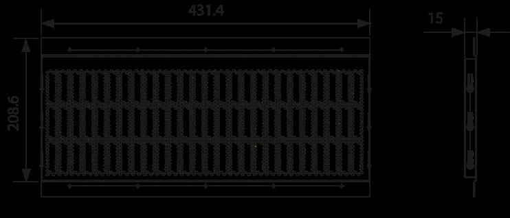
T
CODING STUD
■ For SNCF back frame
■ Galvanised steel
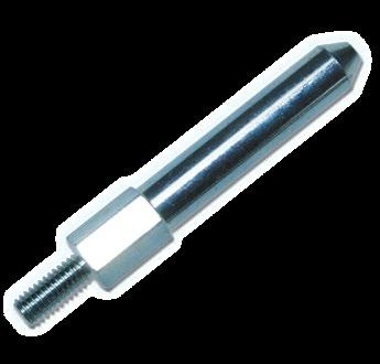
■ Backplane can be used as a shielding rear panel
■ For horizontal contact the internal extrusion has to be mounted without insulation strips
■ Carrying plate has to be mounted directly on the side panel
Scope of delivery:
■ 2 carrying plates, aluminium, conductive incl. assemby material (Torx)
■ 2 EMC contact strips
■ For 6 U are 2 sets required
■ For front panels, fixing on extrusion
■ Self-adhesive
■ Scope of delivery: 2 contact strips
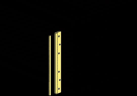
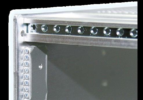
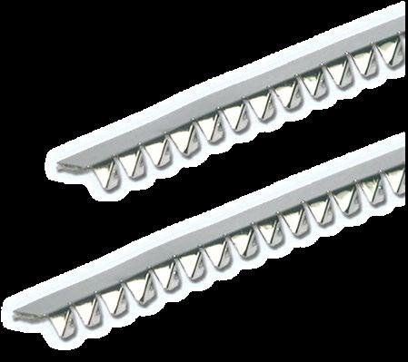
■ One slot per front panel
■ Application: height extrusion front/rear, front panel
■ Gasket slides onto extrusion

CONVERSION TABLE U ASSEMBLY HEIGHTS (NOMINAL HEIGHT)
CONVERSION TABLES
DIMENSIONS SUBRACK
FRONT VIEW
LAYOUT
83 x 5.08
84 x 5.08 ( 426.72)
Abmessungen Gehäusemontage > 450 ≤ 449 (inkl. Montage Hardware) 85 TE
5.08 Abstand für Federleistenhilfspro l
TE TE
Detail X theor Abmessungen
The tolerance between two holes within a distance of 1 m is ± 0.4 mm
POSITION
DIMENSIONS PLUG-IN ASSEMBLY
WITH FRONT PANEL AND CONNECTORS ACCORDING TO IEC 60297
GENERAL CARD
| ALL DIMENSIONS ACCORDING TO IEC 60297-3
DIMENSIONS PLUG-IN ASSEMBLY
DIMENSION DRAWING FOR (HC) 100 MM (FOR 3 U) | DERIVED FROM THE IEC 60297 STANDARD FOR CONNECTORS
DIMENSION DRAWING FOR (HC) 233.35 MM (FOR 6 U) | DERIVED FROM THE IEC 60297 STANDARD FOR CONNECTORS
DIMENSION DRAWING FOR (HC) 366.7 MM (FOR 9 U) | DERIVED FROM THE IEC 60297 STANDARD FOR CONNECTORS
DIMENSIONS PLUG-IN ASSEMBLY CODING KEY
Baugruppenträger, Sicht Frontseite
Codierkammern am Baugruppenträger oben
Codierkammer am Baugruppenträger unten
Codierstift Position N = kein Codierstift
Steckbaugruppe, Sicht auf Frontplatten Rückseite Codierung
Codierkammern an der Steckbaugruppe oben
Codierkammer am Baugruppenträger unten
Codierstift Position
Note: The corresponding keying cavities on the backplane and plug-in board have the same letters. The numbering structure of the coding pins as shown here was chosen with the purpose that the chambers with the identically mounted pins do not block when inserting a plug-in module. If the corresponding chambers are equipped with differently mounted pins, the plug-in unit will be blocked and cannot be inserted. On the front of the subrack / plug-in module are the letters A, B, C below and D, E, F above. The order on the back is mirrored.
Anmerkung: Die entsprechenden Codierkammern am Baugruppenträger und an der Einsteckbaugruppe verfügen über die gleichen Buchstaben. Der Nummerierungsaufbau der Codierstifte wie dargestellt wurde mit dem Zweck gewählt, dass die entsprechenden Kammern mit dem baugleich montierten Stiften beim Einsetzen einer Steckbaugruppe nicht blockieren. Wenn die entsprechenden Kammern mit unterschiedlich montierten Stiften ausgerüstet sind, wird die Steckbaugruppe blockiert und kann nicht eingesetzt werden. Auf der Frontseite des Baugruppenträgers/Steckbaugruppe sind die Buchstaben A, B, C unten und D, E, F oben. Die Reihenfolge auf der Rückseite ist spiegelverkehrt (1,6)
ARRANGEMENT RELATIONSHIP EMC FRONT PANEL / PRINTED CIRCUIT BOARD
■ Protection against contact and contaminants according to IEC60529
■ Liquid ingress protection according to IEC60529
■ Evaluation of the classification:
■ The test results according to the standard do not completely rule out leaks, so an individual test (with the actual device configuration) is recommended in critical cases
■ The degree of protection for cabinets and housings is specified with IP (International Protection) and two code numbers
Protection against water ingress from water jets from all directions
Complete protection against touching internal parts and protection against dust deposits
Elma has recognized the increasing importance of electromagnetic compatibility (EMC) and now has a wide range of protective measures and accessories to offer your electronics good protection.
Typical attenuation (curve) EMC level superior
Typical attenuation (curve) EMC level superior
Electromagnetic compatibility is the ability of a system to operate without interference in its operating environment and not to interfere with it. Thus, the EMC characteristics of a system consist of adequate immunity (immunity) and limited emission of interference (immunity).
The operation of many electrical and electronic devices, e.g. devices with microprocessors, involves the switching of voltages or currents. This creates electromagnetic fields. These propagate from the electronic components into space and couple into cables. The figure shows the effect of a housing shield. It protects the sensitive electronics from external interference and limits the emission of interference.
Störquelle
Störsenke
Störsenke
Störquelle
An enclosure acts as a barrier between the interferer and the victim. The intensity of the waves is dampened and further propagation is prevented. The shielding attenuation describes the effectiveness of the metal shield. It is defined as the logarithm of the ratio of the field strength outside and inside the enclosure.
The overall shielding consists of the absorption loss and the reflection loss. The absorption attenuation is caused by the energy dissipation in the screen material. It is directly proportional to the material thickness. In the lower frequency range, adequate shielding can only be achieved through absorption damping. The return loss is caused by reflections of the electromagnetic wave on the surface of the shielding material. A distinction is made between the reflection loss in the near field (distance from the source of interference < λ /2π) and far field (distance from the source of interference >λ /2π).
c
λ = f
λ = Wavelength of the interference signal in m
c = Speed of light 3 x 10⁸ m/s
f = Frequency in Hertz
Example of determining the total shielding effectiveness of a shield made of 1 mm thick sheet iron and 1 mm thick sheet aluminum at a frequency of 10 kHz and a distance of 0.1 m from the source of interference.
Absorption attenuation
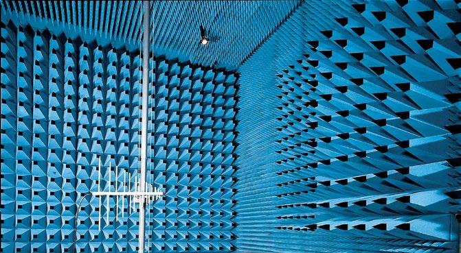
Reflexion attenuation in the near field Eisenblech 1 mm
Attenuation in dB
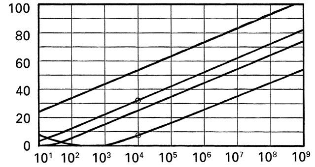
Absorptionsdämpfung
Overall screening attenuation
1 mm
10 dB
6 dB
32 dB
25 + 6 = 31 dB
32 +10 = 42 dB The aluminum sheet screen has an attenuation of 11 dB, i.e. 3.5 times better than the iron sheet screen.
Great attention must be paid to cable entries in housings. Errors in the routing of cables can lead to the desired shielding effect failing almost completely. The following options are available for correctly routing the incoming cables.
The ideal shielding can be achieved by inserting the electronics in a metal housing that is welded on all sides. In practical applications, however, this is only possible in the rarest of cases. Openings are necessary for the operation and display of the electronics, for the passage of cables, for the dissipation of heat loss and for the installation and removal of components. In order to prevent a reduction in attenuation, the individual parts of the housing must be conductively connected. Without conductive seals or contacting via contact points that are close together (e.g. screws), slots are created which, due to their length, create antenna effects. Slot lengths shorter than 1/20th of the wavelength only slightly affect the shielding of a housing. For devices that are exposed to particularly strong radiation, the slit length should be kept less than 1/50th of the wavelength.
1. Possibility
Decoupling capacitors. All conductors of the cable are decoupled via a small value (10 nF) and very short capacitor connections against the housing.
2. Possibility
Shielded cables. The shield is in contact with the housing all around via a cable gland or via a metal connector housing.
3. Possibility The filter must be screwed onto a well conductive surface of the housing.
EMC seals
The most important function of an EMC gasket is to reduce the transition impedance from one part of the housing to the other. The smaller the junction impedance, the better the seal. The contact impedance depends on the surface resistance of the housing parts, the adaptability of the seal, the contact pressure and the conductivity of the seal. It is extremely important that the EMC seal functions in extreme environmental conditions, e.g. damp heat, etc.
The Elma EMC concept is based on three levels of attenuation. As a result, specific needs can be covered at low cost and, if necessary, modules can be retrofitted. The three levels differ in the different lengths of slots between the defined contact points. The slot lengths (create antenna effect) determine the HF tightness.
■ All housing parts are conductively connected to each other
■ Long slits
■ For applications in the low frequency range
EMC Level Advanced
■ All housing parts are conductively connected to each other
■ Slot lengths shortened by additional contact points
■ For applications in the medium frequency range
■ All housing parts are conductively connected to each other
■ Slits closed by EMC gaskets
■ For applications in the high frequency range
The shielding effect of a housing remains a theoretical consideration as long as the built-in components, cable bushings and housing openings are not taken into account. However, the measured damping values of the Elma housing provide basic information about their quality. For most applications, a housing is sufficient whose components are connected to one another with good conductivity. Equipment for data processing (digital technology) produces practically no interference in the frequency range >100 MHz and does not respond to interference in this frequency range, provided the printed circuit boards have been carefully designed. Final results only show measurements on completely dismantled, wired and connected devices. Good electromagnetic compatibility is the result of a well thought-out concept.
The weakest element determines the overall immunity!
In order to dissipate the heat generated in electronic devices, simple convection is often no longer sufficient. The trend towards miniaturization and high packing densities easily lead to the maximum permissible temperature being exceeded, which has a significant impact on the service life of the electronic components. A significant improvement can be achieved by "active air cooling". Important requirements placed on air cooling are low noise levels and the possibility of partial cooling. Elma offers you the optimal solution with the comprehensive range of fan trays for 19" cabinets as well as for 19" subracks and desktop housings
The cooling air volume flow “V” required for cooling an electrical device depends on the power loss “PV ” generated in the device and the temperature difference “∆ϑ” between the permissible operating temperature of the components ϑB and the ambient temperature ϑU of the device.
The required cooling air volume flow at a given operating temperature of the components can be determined to a good approximation using the following equation:
Permitted temperature increase
3.1· PV V = ––––––
V (m3/h) = Cold air volume flow
PV (W) = Dissipation
∆ϑ (K) = Temperature difference ϑB– ϑU 1 3.1 = Constant from C–––––P · ϕ Wh CP = Isobaric specific heat capacity (0.27 ––––) kg k kg
ϕ Air density (1.20 – –) bei 20 °C m3
The fan trays were tested in an Elma type 14 case. 21 double Euro cards with approx. 25 watt power loss per card at a distance of 4 HP (1 HP = 5.08) formed the framework for the performance test of our fan trays. A possible ∆ϑ depending on the power loss P can be determined on the diagrams below.
ϑ = ϑCircuit b – ϑenvironment
Fan tray 1 HE | vertical air intake (3 fans 69–430–20)
Fan tray 2 U | vertical air intake (3 fans 1925–79)
Fan tray 2 U | horizontal air intake (3 fans 1925–79)


Elma Electronic AG, Switzerland
Hofstrasse 93
CH-8620 Wetzikon
T: +41 44 933 41 11
F: +41 44 933 42 15 sales@elma.ch
Elma Electronic GmbH, Germany
Stuttgarter Strasse 11
D-75179 Pforzheim
T: +49 7231 97 34 0 F: +49 7231 97 34 97 info@elma.de
Elma Electronic France SA 16 rue Hannah Arendt
F-67200 Strasbourg
T: +33 3 88 56 72 50 sales@elma-electronic.fr
Elma Electronic UK Ltd.
Solutions House
Priory Business Park
Fraser Road
Bedford MK44 3BF
Great Britain
T: +44 1234 838822
F: +44 1234 836650 sales@elma.co.uk
Elma Electronic Romania SRL
Chisoda, DN 59 km8 + 550m
RO-307221 Judetul Timis
T: +40 374 480 400
F: +40 256 249 820 sales@elma.ch
Elma Electronic Israel Ltd. 34, Modi'in St., I.Z.Sgula IL-49271 Petach-Tikva
T:. +972 3 930 50 25
F: +972 3 931 31 34 sales@elma.co.il
Elma Electronic Inc., USA 44350 S. Grimmer Blvd Fremont, CA 94538, USA
T: +1 510 656 3400
F: +1 510 656 3783 sales@elma.com
Optima Stantron, USA 2305 Newpoint Parkway Lawrenceville, GA 30043, USA
T: +1 770 496 4000
F: +1 770 496 4026 sales@elma.com
Elma Electronic Private Ltd., India
Green Arch 3rd Phase 1st Main
J.P. Nagar Bangalore 560078 sales@elma.com
Elma Electronic Technology (Shanghai) CO., LTD., China No. 11 Building, No198 Chang Jian Road, Bao Shan District CN-200949 Shanghai
T: +86 21 5866 5908 F: +86 21 5866 5918 sales@elmachina.com
Elma Asia Pacific Pte. Ltd., Singapore 8 Ubi Road 2 # 07-14 Zervex Building SG-408538 Singapore
T: +65 6479 8552
F: +65 6479 8662 sales.elmaap@elma.com Your Partner