SYSTEM SOLUTIONS
ENCLOSURES AND COMPONENTS
ROTARY SWITCHES


SYSTEM SOLUTIONS
ENCLOSURES AND COMPONENTS
ROTARY SWITCHES
The interface to the user
Das Nonsequam ab idit quam fuga. Nem quate comnihitis quia sit, abore volo earumqu odiorem porecum nimus aut qui aut et, nonse volupta tempeli busani nobis et aliati numque post, ut ute cus vitiatur antium volupta nullestiis magnisc ientiore estrum eatur, ipic tenimet occus natios ma dendict otatece pereror ad ma ate aut fuga. Musam andae pos et hitasit idelit, unt.
The control panel is not just the face of your device. It is also the so-called HMI (Human Machine Interface) and forms the connection between the device, the controller or electronics and the human being. This makes it one of the most important parts of the device. In addition to the aesthetic aspects, a front panel used as an operating unit must also meet technical and user-specific aspects, such as mechanical resistance or EMC protection. Elma offers the right front panels and services for all kinds of applications.
› Aluminium 2.5 mm, clear anodised (non-conductive)
› 2 HP version: screw retainer cannot be fitted
Scope of delivery:
› 1 Flat front panel
2
3
4
* Coverplates for 1 U fan opening ** Installation of screw lock not possible
Front Panel Screws:
› Set of 10 screws, M2.5 x 11.3 ( with screw retainer)

› Electromagnetic comptability is the ability of a system to operate in the intended environment without causing or suffering unacceptable degradation of performance due to unintentional electromagnetic radiation or response
› Elma’s EMC concept: three levels of electromagnetic shielding performance (Performance Level) Test setup:
The first measurement E1 is without the enclosure. The next measurement E2 is made with the transmitting antenna installed inside the enclosure. The difference between the received signal without and with the enclosure represents the shielding effectiveness in dB.
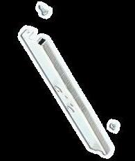
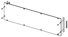
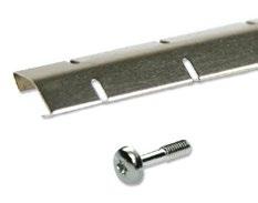
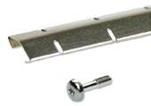
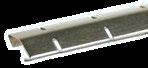
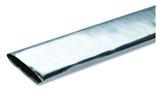
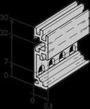
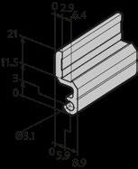
EMC Filler Panel with EMC Gasket
› High stability (U-profile)
› Extruded aluminium
› Pressed-in centring pin and bushes M2.5
› Front side clear anodised, rear side conductive, strong extrusion
Scope of delivery:
› 1 EMC front panel incl. pressed-in centering pin and bushes M2.5
EMC Gasket (Stainless Steel):
Front Panel Screws:
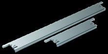
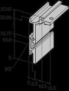
EMC Filler Panel without EMC Gasket
› Front panel standard, solid
› Front clear anodised
› Rear conductive
› Basic level EMC
Scope of delivery:
› 1 front panel incl. press-fit bushes M2.5 (pressed-in)
4 HP 21B304
10 HP 21B310
12 HP 21B312
16 HP 21B316 21B416
21 HP 21B321 21B421
42 HP 21B342 21B442 21B642
63 HP 21B363 21B463
84 HP 21B384 21B484 21B684
Front Panel Screws:
› Front panel width up to 9 HP = 2 screws; ≥ 10 HP = 4 screws
Torx screw, M2.5 x 11.3, size T8 5443-08
Rounded head screw, cross recessed M2.5 x 12.7 61-287
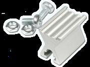
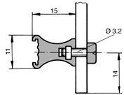
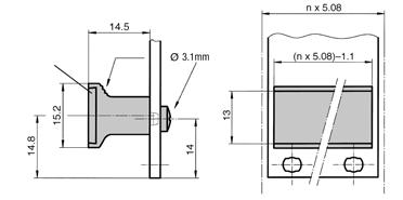
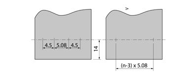
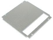
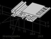
Spacer for EMC Front Panel Flat Advanced Level
Scope of delivery:
› 1 spacer incl. gasket
› 2 Torx sheet metal screws 2.9 x 6.5; size T 10
Holes in some cases needed for mounting, telescopic rails
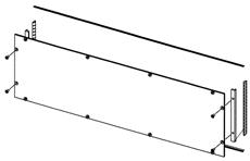
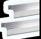
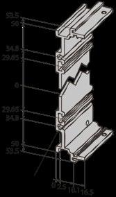
EMC Flat Front Panels Advanced Level
› Aluminium 2.5 mm (conductive)
› Closes the front or rear of the sub rack with very high shielding effectiveness
› Contact between the flat front panel and the case is made via EMC gaskets
Scope of delivery:
› EMC flat front panel
› Contact angle, incl. screws (4 + 6 U version only)
› EMC gasket for contact angle (4 + 6 U version only)
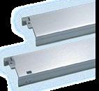
EMC Flat Front Panels Superior Level
Scope of delivery:
› 1 EMC flat front panel
› Contact angle, incl. screws
› EMC gasket for contact angle
› EMC gasket for front extrusion/front Panels
Front Panel Screws, EMC Levels: Advanced and Superior:
› Front panel width 42 HP = 4 screws
› Front panel width 63 HP = 6 screws
› Front panel width 84 HP = 8 screws
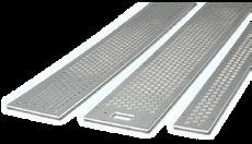
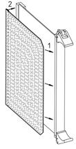
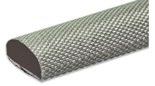
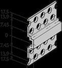
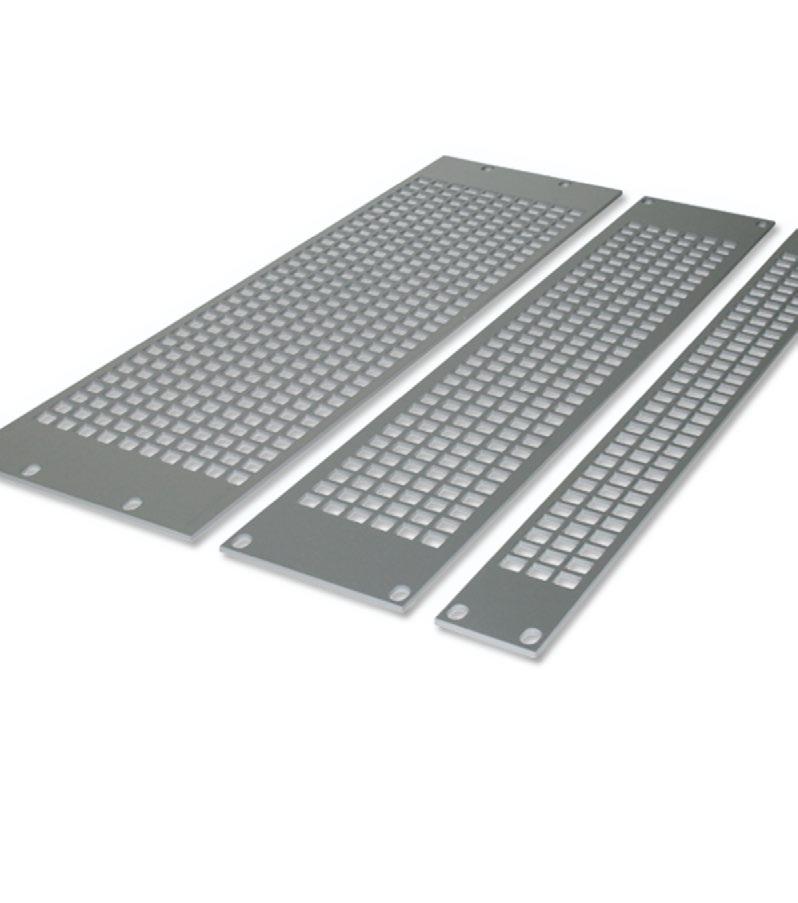
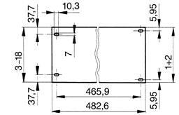
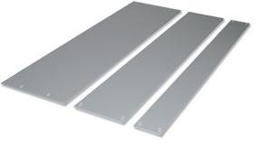
Perforated EMC Front Panel, 84 HP
› Front anodised, rear conductive
› Advanced EMC level
› Width: 84 HP Frontside anodized, Rear conductive
Scope of delivery:
› 1 perforated flat front panel
Torx
Screws
Screws


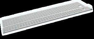
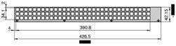
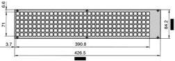
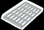
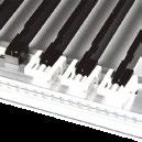
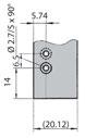
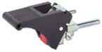
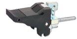
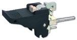
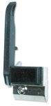
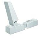
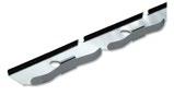
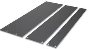
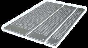
Fan Front Panel for Vertical Ventilation, 84 HP
› Fan front panels are flat, perforated and designed to ensure an optimum air flow rate
› Available with or without switch cut-out (switch opening 1 U = 12.3 x 27.2 mm / 2 U = 22 x 30.6 mm)
› Aluminium 2.5 mm, clear anodised (non-conductive))
Scope of delivery:
› 1 perforated fan front panel


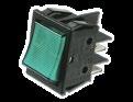
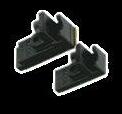
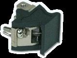
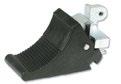
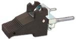
On-Off Switch:
› Black body, plastic
› 2 pole, 250V, 16A
› Quick-connect terminal 6.3 x 0.8 mm
› Cut-out for 4426-00: 22 x 30.6 mm (0.87" x 1.20") / Cut-out others: 12.3 x 27.2 mm (0.48 x 1.07") x 1.07")
On-off switch, indicator light green
On-off switch, without signal light
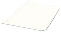
› Aluminium 2.5 mm, clear anodised (non-conductive)
Scope of delivery:
› 1 perforated fan front panel
› Aluminium 2.5 mm, clear anodised (non-conductive)
Scope of delivery:
› 1 perforated fan front panel
Front Panel Screws:
› Set of 10 screws, with screw retainer, per front panel 4 screws are needed


Assembly Material for Fan Mounting:
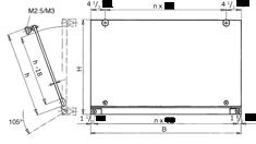
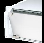
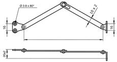
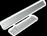
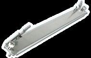
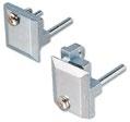
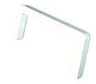
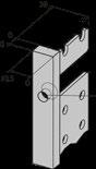
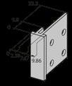
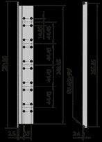
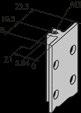
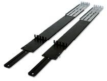
Hinged front panels are ideal for limited access to the assemblies. Hinges can be horizontal or vertical.
Top / Bottom-Hinged Front Panels
› Hinges are attached to the front extrusions of the sub rack or case
› Aluminium 2.5 mm, clear anodised (non-conductive)
Scope of delivery:
› 1 Front panel with hinge extrusion
› Assembly material M2.5, incl. hinges
Dimensions:
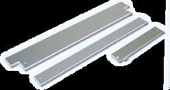
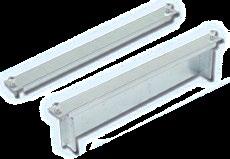
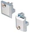
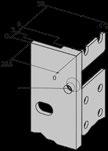
EMC Top / Bottom-Hinged Front Panels
› Width: 84 HP
› Offers optimum protection from electromagnetic interference
› Aluminium 2.5 mm, front anodised, rear conductive
Scope of delivery:
› 1 EMC front panel with hinge extrusions
› Assembly material M2.5, incl. hinges
› EMC gasket
› Aluminium 2.5 mm, clear anodised (non-conductive)
Scope of delivery:
› 1 Front panel with hinge extrusion
› Assembly material M2.5, incl. hinges
Dimensions:
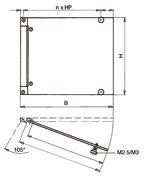
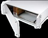
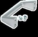
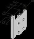
Accessories for Hinged Front Panels
Hinge Extrusions for Top/Bottom-Hinged Front Panels:
Material incl. Hinge Parts for Top/Bottom-Hinged
Hinge Extrusions for Side-Hinged Front Panels:
Assembly Material incl. Hinge Parts for Side-Hinged Front Panels:
Panel Stay:
› 2 panel stay
Front Panels for Plug-in Units
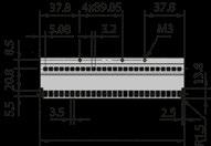
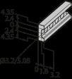
Extruded Front Panel without openings, IEC
› Aluminium 2.5 mm, clear anodised (non-conductive)
› PCB mounting lugs are formed on the rear face of the panel
› No PCB fixing screws on the front face of the panel, leaving more space for silk screening and mounting front panel components
› Suitable for all sub racks and cases
› Thickness of the mounting lugs (3.48 mm) allows PCBs to be mounted on either side of the lugs
› Drill marks at rear for handle-fixing holes
Scope of delivery:
› 1 Extruded front panel, clear anodised)
3 HP 15 0.59 26N303 26N603
4 HP 20.1 0.79 26N304 26N604
5 HP 25.2 0.99 26N305 26N605
6 HP 30.3 1.19 26N306 26N606
7 HP
8
10
12
2.38 26N312 26N612
14 HP 70.9 2.79 26N314 26N614
16 HP 81.1 3.19 26N316 26N616
21 HP 106.5 4.19 26N321
Front Panel Screws:
› Set of 10 screws with screw retainer
› Front panel width up to 9 HP = 2 screws; ≥ 10 HP = 4 screws


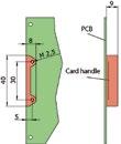
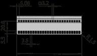
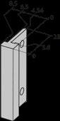
Front Panel with Cut-out for IEC Ejector Handle
› Aluminium 2.5 mm, clear anodised (non-conductive)
› PCB mounting lugs are formed on the rear face of the panel (only 3 U-Version)
› No PCB fixing screws on the front face of the panel, leaving more space for silk screening and mounting front panel components
› 3 U front panels prepared for one handle
› 6 U front panels prepared for two handles
› Suitable for all sub racks and cases
› Ejector handles availbale
Scope of delivery:
› 1 Front panel (clear anodized)
4
6
8
Front Panel Screws :
› Scope of delivery: Set of 10 screws with screw retainer
› Note: Front panel 3 U = 1 screw
Front Panels for Plug-in Units
EMC Filler Panel without Openings, IEC
› Excellent EMC shielding
› Made of aluminium extrusions
› Rear side: conductive surface finish (clear passivated)
› Used in the assembly of plug-in units
› The EMC-gasket is integrated into the front panel profile to protect it from damage
› A pressfit centring pin guarantees optimum positioning of the panel as well as the right pressure between the contact strip and the next panel
Scope of delivery:
› 1 EMC front panel, incl. pressed-in centring pin and bushes M2.5

8
Front panel width up to 8 HP = 2 screws
EMC Front Panels for IEC Plug-In Units with Cut-out for Ejector Handle
› Excellent EMC shielding
› EMC gasket slides onto the extrusion
› Ejector handles and card holder (without anti-twist device or without ESD pin) available
Scope of delivery:
› 1 EMC front panel, incl. pressed-in bushes M2.5 (size ≥ 9 HP)
› Incl. pressed-in centring pin and bush M2.5 (top) › Incl. cut-out for mounting of card holder
1 cut-out (bottom):
4
5
6
8
12 HP 66-522-43 14 HP 66-534-43
Dimensions:
6
Gasket (Stainless Steel):
Front Panel Screws:
›
(top) with screw 5322-08
2 cut-outs (bottom + top):
EMC Front Panels for EMC Gasket, IEEE
› Excellent EMC shielding
› Immune to snagging
› EMC-gasket slides onto the extrusion
› Ejector handles and card holder (without anti-twist device or without ESD pin)
› Front anodised, Rear conductive
Scope of delivery:
› 1 EMC front panel, incl. press-in bushes M2.5 (size ≥ 10 HP)
› Handle needs to be ordered separately
1 cut-out (bottom):
› Incl. pressed-in centring pin and bush M2.5 (top)
› Incl. cut-out for mounting of card holder 61-156 (top) with screw 532208
2 cut-outs (bottom + top):
8
12 HP 66-522-43
14 HP 66-534-43
EMC-Gasket (Stainless Steel):
Front Panel Screws:
› size ≥ 9 HP = 2 additional screws are needed
Dimensions:
EMC Front Panels Aluminium, VPX
› Excellent EMC shielding
› EMC gasket can be inserted on the profile
› In accordance with VPX specifications
› Aluminium extrusion, anodized front, side and rear: conductive
› Front panels with 2 cut-outs (bottom + top); 66-515-43-VPX only 1 cut-out (bottom)
Scope of delivery:
› 1 EMC front panel, Aluminium
› 66-515-43-VPX additionally 1 card holder and assembly material
› EMC gasket and injector handles must be ordered separately
VPX profile front panel, 5
10 pcs. Microswitch for injector handle
AdvancedTCA has several key features including Gigabit/Terabit per second bandwidth across each shelf, 150 - 200 per board and 3 kilowatts per chassis power. It accomodates larger (8 U x 280 mm) boards and a 1.2 mm pitch which allows larger/taller components and more space on each board.
› 8 U x 6 HP
› Conform to the PICMC 3.0 specification
› For boards with thicknesses of 1.6 mm to 2.4 mm
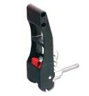
› Made for the ATCA Ergonomic handle family
› Extruded aluminium, clear passivated
› ATCA Ergonomic ejector handles and microswitch for ejector handles
Scope of delivery:
› 1 EMC front panel
› Extruded aluminium
› Visible part of surfaces: Clear anodised; rest: Clear passivated
› ATCA Ergonomic Ejector Handles and microswitch for ejector handles
Scope of delivery:
› 1 EMC front panel
front panel with pinhole for microswitch activation
› Microswitch 81-088 assembled to handle
› Microswitch activation through interlock (sliding button) on handle
› Microswitch 81-088 assembled to front panel
› Microswitch activation through switching pin on lever handle
Front Panel 8 U x 6 HP with Handles, AdvancedTCA
› 8 U x 6 HP with handles
› Conform to the PICMC 3.0 specification
› For boards with thicknesses of 1.6 mm to 2.4 mm
› Microswitch for ejector handles
Scope of delivery:
› 1 galvanised steel front panel incl. captive screws M3
› EMC gasket
› Handle set
Steel front panel with handle 12T100
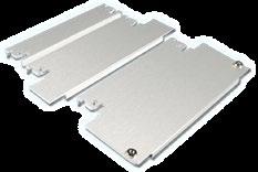
Filler Panel 8 U x 6 HP, AdvancedTCA
Scope of delivery:
› 1 Steel filler panel without baffle, incl. captive screws M3
› EMC gasket
Filler panel steel, incl. captive screws M3
Scope of delivery:
› Steel filler panel with baffle, incl. captive screws M3
› EMC gasket
› Incl. baffles
Filler front panel with baffles 8 U x 6 HP x 270 mm 12T120
Filler RTM panel with baffles 8 U x 6 HP x 72.5 mm 12T121
Captive Screw M3 and Latch Spring Clip:
Screw M3 captive 12T133
Latch spring 12T132
EMC Gasket:
› Polyurethane foam core
› Conductive fabric (Cu + Ni plated)
EMC gasket triangular. 2.3 x 10 mm, L = 300 mm 7821-300 EMC gasket triangular. 2.3 x 10 mm, L = 2000 mm 7821-2000
› Acc. to IEEE 1386
› Used on VME-, Future, CPCI- or Multibus II-Boards when additional interfaces are needed
› On a double euro board (6 U / 4 HP) maximum two PCI mezzanine cards can be placed
› Two designs are available: Zinc die-cast or aluminium extrusion
› Mezzanine filler panel: To cover the unused Mezzanine cut outs.
› Filler panels are simply clipped into the cut outs.
› EMC gaskets can be inserted into the groove of the front panels
Scope of delivery:
› 1 mezzanine front panel
› 1 gasket
› 2 screws M2.5 x 6 mm
FPGA Mezzanine Card or FMC (Vita 57.1) describes a specification of I/O mezzanine modules in conjunction with FPGA or another device with configurable I/O capability. The low-profile design allows use on any industry standard slot card with form factors such as VME, VPX, CompactPCI, AdvancedTCA, MicroTCA, PCI, PXI, and many others. The compact size is very highly adaptable to many configuration requirements and complements existing mezzanine technologies such as PMC.
› Front anel in accordance with VITA 57.1 for FPGA Mezzanine Card (FMC)
› Material: Aluminium
› The EMC gasket is inserted into the groove on the front panel
Scope of delivery:
› 1 Mezzanine FMC front panel, Aluminium, anodized front, rest: conductive
› 1 EMC gasket (elastomer)
› 4 cylinder screws with cross recess M2.5 × 6 mm
› 21M2080-2 additionally: 2 standoffs 10mm, 4 screws
Accessories
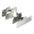
› The card lock is easily mounted onto the upper or lower front profile
› When the PCB is pushed home, it is automatically locked into position
› The card eject mechanism can be attached to the top or bottom front edge of the PCB and is used in conjunction with the card lock
› The lever action ensures smooth and jerk-free card removal, especially useful when multi-pole connectors are being used
› Transparent windows in different colours and self-adhesive labels set into the front face of the eject mechanism make card identification easy
› The card lock and eject mechanism does not inhibit the use of front panels
› For recessed cards, a special card lock is available, suitable for use with profile 66-144
Labels:
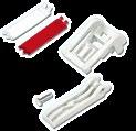
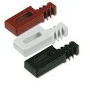
Card Handles
› Coloured, transparent handles which will accept labels facilitate the handling and identification of PCBs
Scope of delivery:
› 1 card handle
› Two screws M2.5 x 5 are needed per handle and have to be ordered separately
* Replacement: order in the future 10 x 61-144 Other colours (blue, yellow, green, orange) upon request

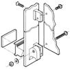
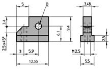
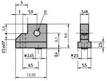
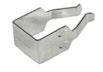
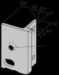
› By using the zinc die-cast card holder, flat front panels can be connected to a PCB to form a plug-in unit to IEC 60297
› The card can be mounted both in the standard position and offset 1 HP (5.08 mm)
› For better positioning of 6 U cards, there is a card holder centre piece made of nylon (see 2.5.13)
› The injector / ejector handle can be used with the card holder
› Front panels are custom made with the necessary cut-outs
Scope of delivery:
› 1 card holder
Card Holder without Swivel Stop
Card Holder with Swivel Stop

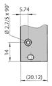

› Usable for all front panels
› For positioning and fixing of 6 U and 9 U PCB
› Card thickness 1.6 mm
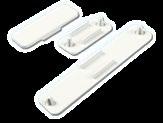
› Self-adhesive, can optionally be screwed on to front panel and printed board
› Material: Plastic black UL94 V-0-0
Scope of delivery:
› 1 plastic middle part
Assembly Material:
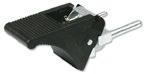
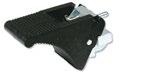
1. Slide protective cover between front panel and printed board
2. Press adhesive tape on protective cover through pins of connectors to attach onto printed board
› Material: Polyester film mat, thickness 0.2 mm, UL94 VTM-2
› Mechanical protection of soldering side
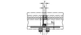
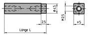
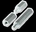
› Four-sided, nickel-plated brass spacers with M2.5 internal threads at both ends
› Using these spacers, additional PCBs may be mounted at a horizontal pitch of 5.08 mm
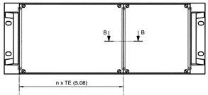
› Mounting plate is 1.5 mm galvanized steel with mounting holes corresponding to PCBs conforming to IEC 60297
X x 5,08 -1,6 (X-1) x 5,08
Spacers
SPACERS SERIES A
› Between PCB mounting lugs & PCBs
› Gives 5.08 mm pitch
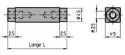
SPACERS SERIES B
› Between two PCBs
› Gives 5.08 mm pitch
Mounting
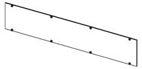
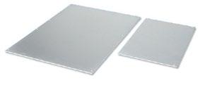
› Dimensions identical to eurocard dimensions
› 1.5 mm galvanized sheet steel
Scope of delivery:
› 1 mounting plate
n 5.08 = theoretical width of front panel
x * 5.08 = distance of printed PCBs
n = multiple of the 5.08 pitch of the selected front panel
x = selected multiple of the 5.08 pitch for the distance of printed PCBs
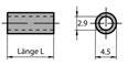
SPACERS SERIES C
› Between a PCB with connector and a second PCB
Accessories
› Galvanised steel
› Ideal for use as supports or spacers
Scope of delivery:
› 1 spacer
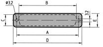
› The caps fit openings for D-Sub connectors and can be fitted without special tools
› Material: ABS grey UL94-HB
Scope of delivery:
› Plastic covering caps
› Assembly of a separation
› Separations are manufactured as required by the customer
› Sheet steel
Scope of delivery:
› 1 mounting bracket

Assembly material
Suitable for applications in 19" format or other enclosures
When building and developing 19'' assemblies or other types of enclosures, suitable accessories are particularly important. According to the IEC, IEEE or AdvancedTCA standards, you will find the right handles for your application at Elma. Of course, the necessary components such as handles or housing feet are also available for the construction of complete subrack solutions.
› Extruded aluminium handles, shaped to facilitate withdrawal of plug-in units
› Two grooves in the front face will accept identification strips (0.5 x 9 mm)
Scope of delivery:
› 1 extruded handle, clear anodised
› Assembly material
8
› Shape/finish and mounting position which correspond to those of the injector/ejector handles
› 4 HP to 12 HP injection-moulded in black glass reinforced Nylon (UL94 V-0)
› 14 HP to 84 HP are extruded in black Noryl (UL94 V-0)
› Aluminium identification labels are inserted into a slot in the handle
› Handles are fixed to the front panels using self-tapping, self-centring screws
› Handles for 4 HP have positioning nipples, allowing them to be fixed with one screw, without turning
› Width greater than 4 HP, at least two screws must be used for fixing
› Grooves on the handle always point towards the middle of the unit
Scope of delivery:
› 1 rigid-mounted handle with identification label
4 HP 10 Pcs. 60-200-04
5 HP 10 Pcs. 60-200-05
6 HP 10 Pcs. 60-200-06
7 HP 10 Pcs. 60-200-07
8 HP 10 Pcs. 60-200-08
10 HP 10 Pcs. 60-200-10
12 HP 10 Pcs. 60-200-12
14 HP 1 Pce 60-200-14
Assembly material:
Cross recessed rounded head screw 61-276

› Simple assembly of plug-in units
› Allows trouble-free extraction of electronic units with multi-pole connectors
› Main features in one part: card holder, ejector handle and centring pin
› Reset spring for safe insertion
› One version for top and bottom only
› Handle is injection moulded, glass-reinforced plastic, UL94 V-0
› Card holder is zinc die-cast, nickel plated
› Reset spring in stainless steel
Scope of delivery:
› 1 Ejector handle
› Assembly material (cross recessed screws M2.5 for fixing of card holder/printed board/front panel)
Injector/Ejector Handles IEEE
Ergonomic Hot-Swap Injector/Ejector Handle, IEEE
› Without latching (standard)
› Maximum recommended force per handle 550 N
Scope of delivery:
› Handle black (plastic, UL94 V-0)
› Card holder (nickel plated)
› Reset spring (stainless steel)
› Assembly material (screws M2.5 for fixing of card holder/printed board/front panel)
Injector/Ejector Handle Top with ESD Pin, black 81-075
Injector/Ejector Handle Bottom with ESD Pin, black 81-076
Ergonomic Injector/Ejector Handle Top with ESD Pin, grey 81-077
Ergonomic Injector/Ejector Handle Bottom with ESD Pin, grey 81-078
Injector/Ejector Handle Top without ESD Pin, black 81-075-01
Injector/Ejector Handle Bottom without ESD Pin, black 81-076-01
Ergonomic Injector/Ejector Handle Top without ESD Pin, grey 81-077-01
Ergonomic Injector/Ejector Handle Bottom without ESD Pin, grey 81-078-01
81-075-01
Ergonomic Hot-Swap Injector/Ejector Handle, IEEE
› With latching (hot-swap)
› Maximum recommended force per handle 550 N
› Offset by 2.54 mm (1/2 HP) to the right - thus giving more space on the solder side of the PCB
Scope of delivery:
› Handle black, button red (plastic, UL94 V-0)
› Card holder (nickel plated
› Reset spring (stainless steel)
› Assembly material (screws M2.5 for fixing of card holder/printed board))
Ergonomic Hot-Swap Injector/Ejector Handle Top with ESD Pin, black 81-095
Ergonomic Hot-Swap Injector/Ejector Handle bottom with ESD Pin, black 81-096
Ergonomic Hot-Swap Injector/Ejector Handle top with ESD Pin, grey 81-097
Ergonomic Hot-Swap Injector/Ejector Handle top with ESD Pin, grey Offset 81-182
Ergonomic Hot-Swap Injector/Ejector Handle bottom with ESD Pin, grey Offset 81-183
Ergonomic Hot-Swap Injector/Ejector Handle top with ESD Pin, black Offset 81-184
Ergonomic Hot-Swap Injector/Ejector Handle bottom with ESD Pin, black Offset 81-185
Ergonomic Hot Swap Injector/Ejector top without ESD Pin, black 81-095-01
Ergonomic Hot Swap Injector/Ejector bottom without ESD Pin, black 81-096-01
Ergonomic Hot Swap Injector/Ejector top without ESD Pin, grey 81-097-01
Ergonomic Hot-Swap Injector/Ejector Handle bottom without ESD pin, grey 81-098-01
18.5 x 10 mm:
81-076

81-076-01


Classic Injector/Ejector Handles, IEEE
› Without latching (standard)
› Maximum recommended force per handle 550 N
› Offset version: Offset by 2.54 mm (1/2 HP) to the right; Thus giving more space on the solder side of the PCB
Scope of delivery:
› Handle black, without button (plastic, UL94 V-0)
› Card holder (nickel plated)
› Reset spring (stainless steel)
› Assembly material (screws M2.5 for fixing of card holder/printed board)
Classic Hot-Swap Injector/Ejector Handles, IEEE
› Maximum recommended force per handle 550 N
› Offset version: Offset by 2.54 mm (1/2 HP) to the right; Thus giving more space on the solder side of the PCB
Scope of delivery:
› Handle black, button light grey (plastic, UL94 V-0)
› Card holder (zinc die-cast, galvanized)
› Assembly material (screws M2.5 for fixing of card holder/printed board)
Injector/Ejector
Injector/Ejector
Optional Assembly Material (for Classic Injector/Ejector Handles, IEEE):
Injector/Ejector Handles IEEE
Telecom Hot-Swap Injector/Ejector Handle, IEEE
› With latching (hot-swap)
› Maximum recommended force per handle 550 N
› Offset version: Offset by 2.54 mm (1/2 HP) to the right: Thus giving more space on the solder side of the PCB
Scope of delivery:
› Handle black, button red (plastic, UL94 HB)
› Card holder (zinc die-cast, galvanized)

› Assembly material (screws M2.5 for fixing of card holder/printed board)
Telecom Hot-Swap Injector/Ejector Handle top with ESD Pin, black 81-205
Telecom Hot-Swap Injector/Ejector Handle bottom with ESD Pin, black 81-206
Telecom Hot-Swap Injector/Ejector Handle top with ESD Pin, black offset 81-188
Telecom Hot-SwapInjector/Ejector Handle bottom with ESD Pin, black offset 81-189
Telecom Hot-Swap Injector/Ejector Handle top without ESD Pin, black 81-205-01
Telecom Hot-Swap Injector/Ejector bottom without ESD pin, black 81-206-01
Telecom Long Hot-Swap Injector/Ejector Handle, IEEE
Scope of delivery:
› Handle black, button red (plastic, UL94 HB)
› Card holder (zinc die-cast, galvanized)
› Assembly material (screws M2.5 for fixing of card holder/printed board)
Telecom Long Hot-Swap Injector/Ejector Handle top with ESD Pin, black 81-214
Telecom Long Hot-Swap Injector/Ejector Handle bottom with ESD Pin, black 81-215
Telecom Long Hot-SwapInjector/Ejector Handle bottom with ESD Pin, black offset 81-116
Telecom Long Hot-Swap Injector/Ejector Handle top with ESD Pin, black offset 81-117
Optional Accessoiries:


Injector/Ejector Handles IEEE
Cut-outs and Functions
Injector/Ejector Handle without Locking Function
Injector / Ejector Handle
Injection Front panel Printed bord
Ejection
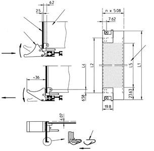
usable height for front components
Injector/Ejector Handles with Locking Function
Injector/Ejector Handles IEEE Injection Front Panel Printed bord
Injector / Ejector Handle
Ejection
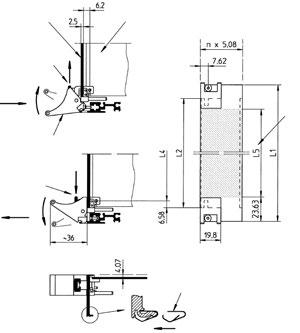
Injector/Ejector Handles Offset with Locking Function
Injection
As soon as the handle reaches its end position (plug-in unit fully seated) it is automatically locked (microswitch actuates).
Dimensions:
Ergonomic Bottom With ESD Pin Black
Ergonomic Top With ESD Pin Black
Ergonomic Bottom Without ESD Pin
Ergonomic Top Without ESD Pin Black
Ergonomic Hot Swap Bottom With ESD Pin Black
Ergonomic Hot Swap Top With ESD Pin Black
Ergonomic Hot Swap Bottom Without ESD Pin Black
Ergonomic Hot Swap Top Without ESD Pin Black
Ergonomic Hot Swap Offset Bottom With ESD Pin Black
Ergonomic Hot Swap Offset Top With ESD Pin Black
Classic Bottom With ESD Pin
Classic Top With ESD Pin
Classic Offset Bottom With ESD Pin
Classic Offset Top With ESD Pin
Classic Hot Swap Bottom With ESD Pin
Classic Hot Swap Top With ESD Pin
Classic Hot Swap Offset Bottom With ESD Pin Black
Classic Hot Swap Offset Top With ESD Pin Black
Telecom Hot Swap Bottom With ESD Pin Black
Telecom Hot Swap Top With ESD Pin Black
Telecom Hot Swap Bottom Without ESD Pin Black
Telecom Hot Swap Top Without ESD Pin Black 81-205-01*
Telecom Hot Swap Offset Bottom With ESD Pin Black
Telecom Hot Swap Offset Top With ESD Pin Black
Telecom long Hot Swap Bottom With ESD Pin Black 81-215
Telecom long Hot Swap Top With ESD Pin Black 81-214
Telecom long Hot Swap Offset Bottom With ESD Pin Black 81-116
Telecom long Hot Swap Offset Top With ESD Pin Black 81-117
Microswitch 81-088-1 (10 Pcs.)
Injector/Ejector Handles IEEE
Microswitch
Technical data:
› Life circuit:: 30 V DC, 5 - 50 mA | 30’000 cycles
60 V DC, 5 mA | 30’000 cycles
60 V DC, 500 mA | 15’000 cycles
› Temperature: -25 bis +70 °C
› Humidity: max. RH 85 %
› Vibration: 10 bis 55 Hz, 18 g
› Shock: 30 g, 11 ms
Microswitch with pre-assembled wire cable length (25 mm) 81-088-1
Mounting
1. Push microswitch onto the handle
2. Insert the front panel into the handle
3. Screw-on
Scope of delivery:
› End piece card holder (zinc die-cast, nickel plated)
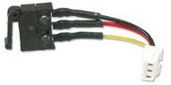
Molex Plug Part-No. 51021-0300 Mates with: 51047-0300, 53048-0310, 53047-0310, 53261-0390, 53398-0390
Switch function:
Switch open: Connection between Pin 1 and Pin 3
Switch closed: Connection between Pin 1 and Pin 2
› Assembly material (screws M2.5 for fixing of front panel/card holder/printed board)
Holder/End Piece with ESD Pin, top
Holder/End Piece with ESD Pin, bottom
Card Holder/End Piece without ESD Pin, top
Card Holder/End Piece without ESD Pin, bottom
› Acc. to IEC 60297-3-103
› Plastic, UL94 V-0
› Can be rotated in 4 positions
Injector/Ejector
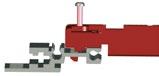
Ergonomic Injector / Ejector Handle, AdvancedTCA
› Pre-assembled
› Self-locking screws for front panel and board mounting (Tuflok)
› Plastic parts black (UL94 V-0)
› Base part including alignment pin (zinc die-cast, nickel plated)
› Other versions available on request
› Prepared for assembly with Microswitch
Scope of delivery:
› Handle pre-assembled
› Retaining scre mounting (loose packed) screw for board mounting (loose packed)
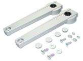
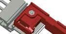
Ergonomic Handles
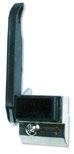
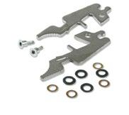
Classic Handle, AdvancedTCA
› Easy operation
› Material: stainless steel
› With latching (hot-swap)
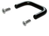
Ergonomic Handle with switching pin on lever handle
Scope of delivery:
› 2 steel handles
› 2 shoulder screws M2.5, Torx size T10
› 4 + 4 washers
› 2 latch spring clips
› Assembly instructions
Microswitch
Technical data:
› Life circuit:: 30 V DC, 5 - 50 mA | 30’000 cycles
60 V DC, 5 mA | 30’000 cycles
60 V DC, 500 mA | 15’000 cycles
› Temperature: -25 bis +70 °C
› Humidity: max. RH 85 %
› Vibration: 10 bis 55 Hz, 18 g
› Shock: 30 g, 11 ms
Microswitch with pre-assembled wire cable length (25 mm) 81-088-1
Molex Plug Part-No. 51021-0300 Mates with: 51047-0300, 53048-0310, 53047-0310, 53261-0390, 53398-0390
Injector/Ejector Handles
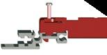
Mounting Microswitch to Ergonomic Handle AdvancedTCA
Easy assembly possible without tools
1. Handle stays in the locked (closed) position
2. Check the microswitch orientation according the drawing below
3. Push microswitch onto the handle
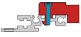
Mounting Microswitch to Front Panel
1. Press studs (Elma part number: 5686-05) into the panel
2. Check the microswitch orientation according the drawing below
3. Push microswitch onto the studs
Fixing material
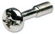
Rounded Head Screw M2.5 x 5 mm
› For front panel mounting
› Self securing (Tuflok)
› Steel, nickel plated
› Phillips #1
Rounded Head Screw M3 x 12.7 mm
› Captive screw for mounting handle to rack
› Steel, nickel plated
› Freedrive, Phillips #2
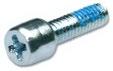
Special Screw M2.5 x 8.3 mm
› Screw for mounting PCB to ATCA Ergonomic handle
› Self securing (Tuflok)
› Steel, gavanised, clear passivated
› Phillips #1

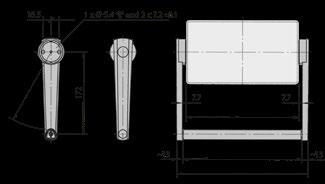
› For portable units up to 6 U
› Sturdy and light
› Easy to assemble
› Carrying capacity up to 30 kg
› Lock in increments of 30°
› Operating temperature –20°C to +60°C
› Fixing material included
Scope of delivery:
› 2 side parts assembled
› 2 raised cross recessed screws M4 x 16
› 2 raised cross recessed screws M5 x 16
› 2 press-in nuts M4
› 4 caps
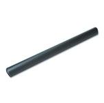
Handle Extrusions:
› Aluminium, coated (soft feel)
Scope of delivery: 1 handle extrusion
› For small components
› Steel powder coated black (RAL 9005)
Scope of delivery:
› 1 Handle
Assembly Material (per handle 2 screws are needed):
U-Handles Aluminium
› Anodised aluminium extrusion
› Width: 9 mm
Scope of delivery: 1 aluminium handle
2
3
4
5
Die Cast Aluminium Handles
› Universal handle
› Wet painted white aluminium (RAL 9006)
› Material 1 U version: Die cast zinc
Scope of delivery:
› 1 die cast handle
Assembly Material (per handle 2 screws are needed):
Assembly Material (per handle 2 screws are needed):

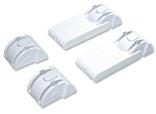
Case Feet Type 15
› With and without tilt feet
› Glass-fibre reinforced plastic, UL94 V-0
› Up to 30 kg carrying capacity per set
Scope of delivery:
› 2 + 2 case feet, incl. rubber inserts NBR
› 8 countersunk PT-screws 3.5 x 8
Case Feet Type 14
› With or without tilt feet
› Glass-fibre reinforced plastic, UL94 V-0
› Up to 30 kg carrying capacity per set
Scope of delivery:
› 4 case feet
› 8 cross recessed countersunk PT-screws 3.5 x 7
› 4 rubber inserts NBR
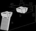
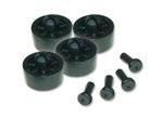
Push in Feet
› Plastic, UL94 V-0
› Easy and fast mounting without tools
› Drilling: Ø8 + 0.1 mm
› Sheet metal: 1 to 2.5 mm
Scope of delivery:
› Set of 4 pieces plastic feet incl. push rivet
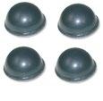
Bumpon
› Self adhesive bumpon
› Black polyurethane, UL94 HB
Scope of delivery:
› 1 Bumpon


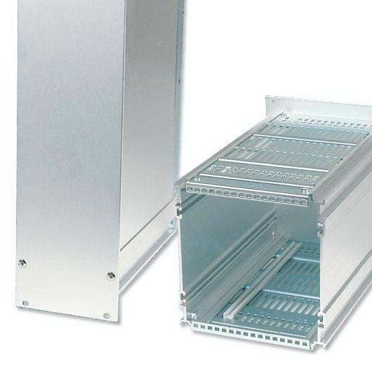
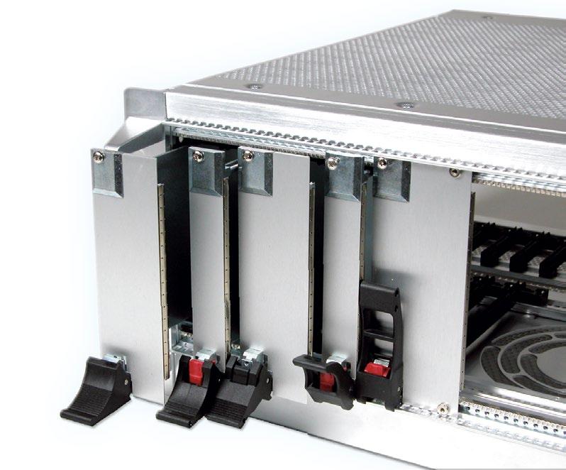
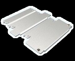
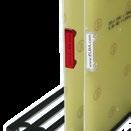
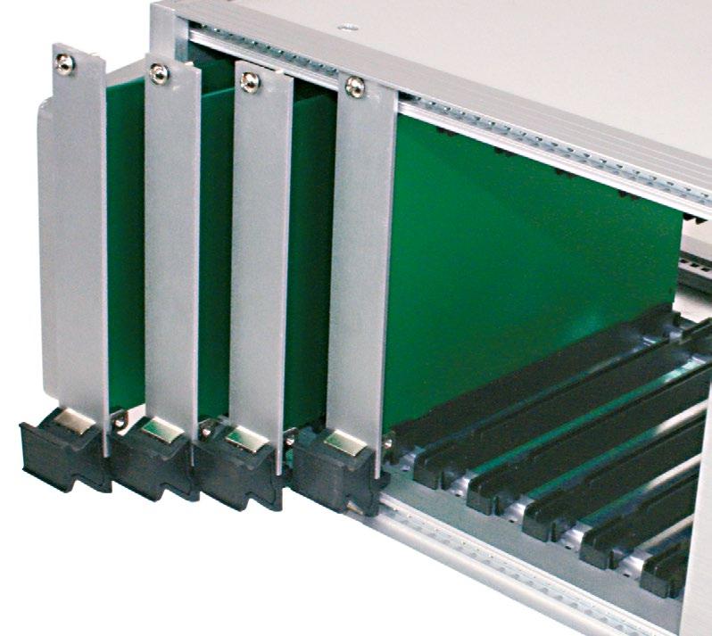
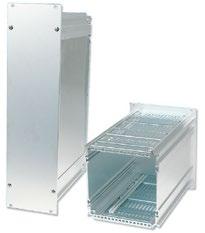
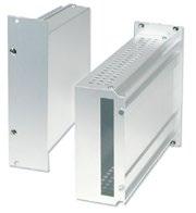
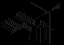
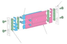
The best Protection for your Plug-in Unit
Das Nonsequam ab idit quam fuga. Nem quate comnihitis quia sit, abore volo earumqu odiorem porecum nimus aut qui aut et, nonse volupta tempeli busani nobis et aliati numque post, ut ute cus vitiatur antium volupta nullestiis magnisc ientiore estrum eatur, ipic tenimet occus natios ma dendict otatece pereror ad ma ate aut fuga. Musam andae pos et hitasit idelit, unt.
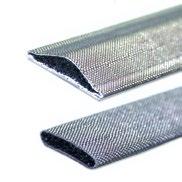
Wherever plug-in assemblies have to be replaced with sensitive electronic units used, a robust cover is highly recommanded. Cassettes offer an optimal mechanical protection for single and double Eurocards. The metal cover also improves the EMC shielding. Openings ensure sufficient ventilation to allow the heat from the built-in components to dissipate.
› Accepts several PCBs on horizontal pitch of 1 HP (5.08 mm, 0.20")
› IEC60603-2 connectors can be mounted internally at rear
› Connectors can be interwired to form a functional plug-in unit
› Suitable for use with all sub racks, adaptation kits for mounting eurocards and eurocard mounting sets
› Several eurocards 100 x 160 mm (3.93" x 6.29") or 100 x 220 mm (3.93" x 8.66") can be fitted
› Several double eurocards 233.35 x 160 mm (9.18" x 6.29") or 233.35 x 220 mm (9.18" x 8.66") can be fitted
› Possibility to mount 100 x 160 mm (3.93" x 6.29") PCBs recessed inside a 100 x 220 mm (3.93" x 8.66") cassette with insertion from front or rear (see wiring example)
› Edge connectors used for interwiring are attached to connector mounting angles at the rear of the cassette
› Card guides are used to locate the cassette in the sub rack
› Right and left side extrusions with grooves for sliding in a PCB
› Installation of further PCB’s by assembly of card guides in the perforated bottom/top covers
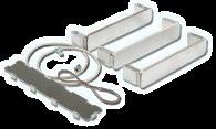
Scope of delivery:
› 1 Front panel
› Side extrusions
› Top/bottom covers
› Mounting angle
› Extension piece
› Assembly material
› Rear panel (6 U version only)
› Side covers (6 U version only)
Mounting options:
*When 160 mm cards are inserted from the rear of a 220 mm cassette, a rear panel is required.
Front Panel Screws:
› Set of 10 screws, M2.5 x 11.3, with screw retainer
› Per cassette A 4 screws are needed
Card Guides:
› For mounting PCBs in cassettes
› Assembly in the perforated bottom/top covers
› Light grey UL94 V-0
Rear Panels:
› For mounting from rear for 160 mm (6.29") cards in cassettes 220 mm (8.66")
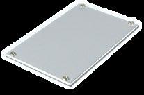
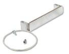
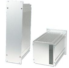
› Accepts one PCB and various non-standard and bulky components which can be mounted using the grooves formed in the side extrusions
› By interwiring the components, the module can be used as functional plug-in unit
› Suitable for use with all sub racks, adaptation kits for mounting eurocards and eurocard mounting sets
› Accepts a eurocard 100 x 160 mm (3.93" x 6.29") or 100 x 220 mm (3.93" x 8.66") and double eurocards 233.35 x 160 mm (9.18" x 6.29") or 233.35 x 220 mm (9.18"x 8.66") fastened to the side extrusions and leaving room for nonstandard and bulky components
› Card guides are used to locate the module in the sub rack
Scope of delivery:
› 1 Front panel
› Side extrusions
› Top/bottom covers
› Rear panel
› Assembly material
› Side covers (6 U versions only)
Front Panel Screws:
› Set of 10 screws, M2.5 x 11.3, with screw retainer
› Per module B 4 screws are needed
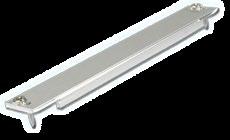
› These narrow modules can be used for the shielding and mechanical protection of single PCBs or as small functional plugin units
› Suitable for use with all sub racks and eurocard mounting sets
› The C-type module accepts one eurocard 100 x 160 mm (3.93" x 6.29") or 100 x 220 mm (3.93" x 8.66") with edge connector to IEC60603-2, types B, C, D
› The closed module provides good shielding and also mechanical protection for sensitive components
› Card guides are used to slide the module into the sub rack
Scope of delivery:
› 1 Front panel
› Side extrusion
› Cover
› Assembly material
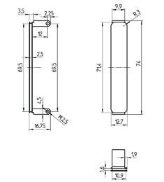
Module C for one Eurocard and Bulky Components
Front Panel Screws:
› Set of 10 screws, M2.5 x 11.3 with screw retainer
› Module C width 7 HP = 2 screws; ≥ 10 HP = 4 screws
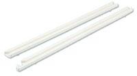
Fluted Handles
› Extruded aluminium handles, shaped to facilitate withdrawal of plug-in units
› Two grooves in the front face will accept identification strips (0.5 x 9 mm)m)
Scope of delivery:
› 1 Extruded handle, clear anodised
› Assembly material
› To build up customised solutions
› For 3 U type 23 cassettes and modules
Scope of delivery:
› 1 Side wall extrusion
› Assembly material has to be ordered separately
› To build up customised solutions
› For 6 U cassettes and modules type 23
Scope of delivery:
› 1 depth extrusion
› Assembly material has to be ordered separately
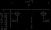
Cassette A and Module B:
Card depth t = 160/220 mm (6.29"/8.66")
Module C:
Module C Cassette A Module B
A
Card depth t = 160/220 mm (6.29"/8.66")
› Fixing screw only
› Screw with threaded bush
› Screw with retainer
› Screw with press-fit bush (M2.5 only)
If threaded bushes are used, the fixing holes must be drilled out and tapped, M5 x 0.5. Elma will perform this task on request.
Reworking is NOT necessary when press-fit bushes are used.
Titel Titel Titel
Titel zweite Zeile
For Plug-in Units
Das Nonsequam ab idit quam fuga. Nem quate comnihitis quia sit, abore volo earumqu odiorem porecum nimus aut qui aut et, nonse volupta tempeli busani nobis et aliati numque post, ut ute cus vitiatur antium volupta nullestiis magnisc ientiore estrum eatur, ipic tenimet occus natios ma dendict otatece pereror ad ma ate aut fuga. Musam andae pos et hitasit idelit, unt.
Card guides ensure your electronics are installed durably in the right place. Suitable for the right standard and the right application, you will find the appropriate card guide in Elma's portfolio.
› For positive location of circuit boards and plug-in units conforming to the dimensions of card depths 80 mm, 160 mm, 220 mm and 280mm
› The card guides are non-flammable, made from a high quality plastic material reinforced with fibreglass UL94 V-0
› Including ESD provision
› According to EN 45545, Level HL3
Scope of delivery:
› 10 Card guide black plastic UL94 V-0
1.6
ESD Clips:
› Connecting printed board with case in stainless steel
› for card guides from 160 mm depth
› MOQ 100 Pcs.
ESD clip front bottom/rear top
ESD clip front top/rear bottom 61-419-02
› For reduced assembly time of multiple slot applications
› For use with single, double and triple eurocards with a depth of 160mm
› For card thickness: 1.6 mm / 0.06"
› Black plastic, UL94 V-0
› ESD Clip not usable
Scope of delivery:
› 1 Card Guide 7-slot, IEC
Card Guides 1-Slot, 3 Parts,
› Extrusion: Aluminium
› End feet: plastic, UL94 HB
› For card thickness: 1.6 mm / 0.06"
› Card guide extrusion, aluminium, clear anodised
› ESD clip not usable
Extrusions:
End Feet:
Card Guide Board-Retention Bar
Scope of delivery:
› 20 Board-retention bar, zinc-plated steel
Assembly Material:
› Simple assembly comparable to anchoring
› Very high retention force
› Shock and vibration proof
› For positive location of circuit boards and plug-in units
› For card thickness 1.6 mm / 0.06” and 2.0 mm/0.08” with anti-vibration feature
› The card guides are non-flammable, made from a highquality plastic material reinforced with fibreglass (UL94 V-0)
› With ESD provision
› Stainless steel PT-screw, Torque: 0,36 Nm.36 Nm
Scope of delivery:
› 1 Card guide, plastic UL94 V-0
› MOQ: 10 Pcs.
Standard Mounting:
› with stainless steel security screw (from top)
› Note: For highest security 2 screws per card guide are necessary
Optional Mounting:
› Per Set 1 M2 with M2 screw, 1 washer and 1 nut (from bottom) needed
› Note: For highest security 2 sets per card guide are necessary

ESD Clips:
› Connecting printed board with case
› MOQ: 100 Pcs.
› For positive location of PCBs and plug-in units conforming to the dimensions of card depths 80 mm, 160 mm, 220 mm, 280 mm and 340 mm
› The card guides are nonflammable, made from a high quality plastic material reinforced with fibreglass (UL94 V-0)
› With ESD provisions
› With keying and alignment pin possibilities
Card Guides 1-Slot, IEEE
› Card thickness 1.6 mm / 0.06” and 2.0 mm / 0.08”
› Plastic UL94 V-0-0
80
160 6.3 black 61-950-01
160 6.3 red
Card Guides 1-Slot, incl. mounted ESD Components, IEEE
› Bottom: 1 ESD clip and 1 ESD spring
› Top: 1 ESD spring
› Black plastic UL94 V-0
Clip
Aluminium Card Guides 1-Slot, 3 Parts, 1.6 mm
› Extrusion: Aluminium
› End feet: Plastic UL94 V-0
› For card thickness 1.6 mm / 0.06" and 2.0 mm / 0.08"
Extrusions:
160 6.30 66-452-20
220 8.66 66-452-25
280 11.02 66-452-30
340 13.38 66-452-35
Aluminium Card Guides 1-Slot, 3 Parts, 2.4 mm
› Extrusion: Aluminium
› End feet: Plastic UL94 V-0
› For card thickness 2.4 mm / 0.094"
Extrusion:
End Feet:
160 6.3 66-453-20
220 8.66 66-453-25
280 11.02 66-453-30 340 13.38 66-453-35
ESD Clips
› Connecting printed board with case
› MOQ: 100 Pcs.
› Notch inward-looking Card Depth
Coding Pins
› Acc. to IEC 60297-3-103
› Plastic, UL94 V-0
› Can be rotated in 4 positions
ESD Springs
› Connecting ESD pin with case

› Simple assembly comparable to anchoring
› Very high retention force
› Shock and vibration proof
› For positive location of circuit boards and plug-in units
› For card thickness 1.6 mm / 0.06” and 2.0 mm/0.08” with anti-vibration feature
› The card guides are nonflammable, made from a high quality plastic material reinforced with fibreglass (UL94 V-0)
› With ESD provision
› With keying and alignment pin possibilities
› Stainless steel PT-screw, Torque: 0,36 Nm
› According to EN 45545, Level HL3
Scope of delivery:
› 1 Card guide, plastic UL94 V-0
› Note: At least one must be used
6.30 black
160 6.30 red 61-970-03
160 6.30 pearlwhite / offset 61-972-01
Standard Mounting:
› With Stainless Steel Security Screw (from Top)
› Note: For highest security 2 screws/card guide, 4 screws/pair are necessary.
Optional Mounting:
› With Set of 1 M2 screw, 1 washer and 1 nut (from Bottom)
› Note: For highest security 2 sets/card guide, 4 sets/pair are necessary.
› MOQ: 100 Pcs.


ESD Clips
› Connecting printed board with case
› MOQ: 100 Pcs.
ESD clip front bottom/rear top 61-419-01
ESD Springs
› Connecting ESD pin with case
› Note: Notch inward-looking
ESD clip front top/rear bottom 61-419-02 Description
› Acc. to IEC60297-3-103
› Plastic, UL94 V-0
› Can be rotated in 4 positions
spring 61-420 Description

› The PICMG® Micro Telecommunications Computing Architecture (MicroTCA™) specification defines the requirements for a system that uses PICMG Advanced Mezzanine Cards (AdvancedMCs) directly on a Backplane. This specification, MicroTCA.0, defines the general mechanical, electrical, thermal, and management properties of a MicroTCA Shelf necessary to support AMC.0 compliant Modules.
› MicroTCA has a primary purpose of serving as a platform for telecommunications and enterprise computer network equipment. Its secondary goal is to function as a platform for other demanding marketplaces, such as Customer Premises Equipment (CPE).
› MicroTCA is complementary to the PICMG3.0 advanced Telecommunications Computing Architecture (AdvandedTCA or PICMG3). Where AdvancedTCA is optimised for very high capacity, high performance applications, MicroTCA is designed to address cost sensitive and physically smaller applications with lower capacity, performance, and perhaps less stringent availability requirements.
› MicroTCA preserves many of the important philosophies of AdvancedTCA, including basic interconnect topologies and management structure
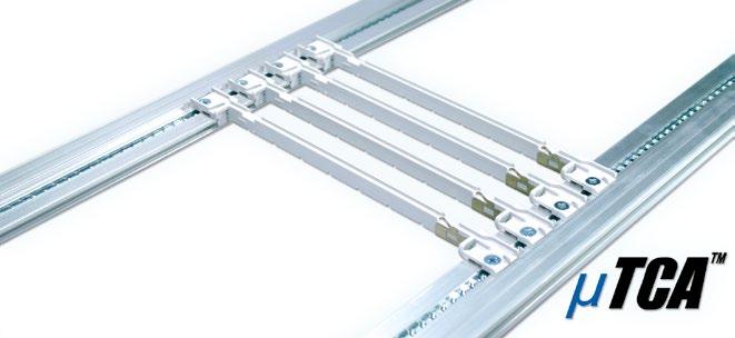
› Made to build uTCA card cages
› Comform to the PICMG specification MTCA.0 R1.0
› Prepared to meet EMC requirements
› Aluminium clear passivated
› Special length or surface treatments on request
MicroTCA Card Guides
› Fits on extrusion 66-242-X
› Top and bottom use of card guide
› Plastic, grey, UL94 V-0
› ESD clip can be assembled at front and rear
Description Part-No.
MicroTCA Card guide 61-193-00
MicroTCA ESD Clip
› Fits on MicroTCA card guide 61-193-00
› Stainless steel
Description Part-No.
MicroTCA ESD clip 61-194
Tapped Strips M3
› 2 x 6 mm M3
› Fit into uTCA extrusion 66-242-XX
› Steel, glavanised, passivated
Countersunk Screw M3 x 6 mm
› Cross recessed, Phillips #1
› Steel, galvanised, passivated
› To assemble MicroTCA card guide and extrusion

› The card lock is easily mounted onto the upper or lower front profile
› When the PCB is pushed home, it is automatically locked into position
› The card eject mechanism can be attached to the top or bottom front edge of the PCB and is used in conjunction with the card lock
› The lever action ensures smooth and jerk-free card removal, especially useful when multi-pole connectors are being used
› Transparent windows in different colours and self-adhesive labels set into the front face of the eject mechanism make card identification easy
› The card lock and eject mechanism does not inhibit the use of front panels
› For recessed cards, a special card lock is available, suitable for use with profile 66-144
Labels:
Card Handles
› Coloured, transparent handles which will accept labels facilitate the handling and identification of PCBs
Scope of delivery:
› 1 card handle
› Note: Per handle two screws M2.5 x 5 are needed, have to be ordered separately
› By using the zinc die-cast card holder, flat front panels can be connected to a PC
› card to form a plug-in unit to IEC 60297
› The card can be mounted both in the standard position and offset 1 HP (5.08 mm)
› For better positioning of 6 U cards, there is a card holder centre piece made of nylon
› The injector / ejector handle can be used with the card holder
Card Holders without Swivel Stop
Card Holders with Swivel Stop
Assembly Material
› Usable for all front panels
› For positioning and fixing of 6 U and 9 U cards
› Card thickness 1.6 mm
› Self-adhesive, can optionally be screwed onto front panel and printed board
› Material: Plastic black UL94 V-0
Scope of delivery:
› 1 Plastic middle part
Assembly Material:
1. Slide protective cover between front panel and printed board
2. Press adhesive tape on protective cover through pins of connectors to attach onto printed boards
› Material: Polyester film mat, thickness 0.2 mm, UL94 VTM-2
› Mechanical protection of soldering side
› Four-sided, nickel-plated brass spacers with M2.5 internal threads at both ends
› Using these spacers, additional PCBs may be mounted at a horizontal pitch of 5.08 mm
› Mounting plate is 1.5 mm galvanized steel with mounting holes corresponding to PCBs conforming to IEC 60297
(X-1) x 5,08
X x 5,08 -1,6
Spacers
SPACERS SERIES A
› Use between PCB mounting lugs and PCBs
› Gives 5.08 mm pitch
SPACERS SERIES B
› Use between two PCBs
› Gives 5.08 mm pitch
Mounting Plates
› Dimensions identical to eurocard dimensions
› 1.5 mm galvanized sheet steel
Scope of delivery:
› 1 mounting plate
n * 5.08 = theoretical width of front panel
x * 5.08 = distance of printed PCBs
n = multiple of the 5.08 pitch of the selected front panel
x = selected multiple of the 5.08 pitch for the distance of printed PCBs
SPACERS SERIES C
› Use between a PCB with connector and a second PCB
› Galvanized steel
› Ideal for use as supports or spacers
Scope of delivery:
› 1 spacer
Covering Caps
› The caps fit openings for D-Sub connectors and can be fitted without special tools
› Material: ABS grey UL94 HB
Scope of delivery:
› 1 Plastic covering caps
Mounting Brackets
› Assembly of a separation
› Separations are manufactured as required by the customer
› Sheet steel
Scope of delivery:
› 1 mounting bracket

Titel Titel Titel
Titel zweite Zeile
Small components for robust solutions
Das Nonsequam ab idit quam fuga. Nem quate comnihitis quia sit, abore volo earumqu odiorem porecum nimus aut qui aut et, nonse volupta tempeli busani nobis et aliati numque post, ut ute cus vitiatur antium volupta nullestiis magnisc ientiore estrum eatur, ipic tenimet occus natios ma dendict otatece pereror ad ma ate aut fuga. Musam andae pos et hitasit idelit, unt.
In addition to the basic components, various small parts are also required to set up 19" systems and plug-in modules. Only the right fastening components in the right place make the system perfect. Elma has a wide range of fastening parts and screws available for an optimal fixation.
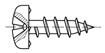
Milled Edge Screw Slotted, Head Ø 7, Press-Fit Bush


Milled Edge Screw Slotted, Head Ø 7, Threaded Bush


Milled Edge Screw Slotted, Head Ø 7, Retainer


Round Head Screw, Head Ø 5 (Torx Ø 6), Press-Fit Bush


Round Head Screw Slotted, Head Ø 5, Threaded Bush


Round Head Screw, Head Ø 5 (Torx Ø 6), Retainer
Milled Edge Screw Slotted, Head Ø 7
Round Head Screw Slotted, Head Ø 5

Phillips M2.5 x 12.7 Steel, nickel-plated 61-287
Phillips M2.5 x 12.7 Steel, nickel-plated, black 61-294
Torx T8 (M2.5 x 11.3 Steel, nickel-plated 5443-08
Freedrive M2.5 x 11.3 Steel, nickel-plated 61-295
Freedrive M2.5 x 11.3 Steel, nickel-plated, black 61-295-01
Press-Fit Bush, Drilling Ø 3.7+0.1/0
M2.5 Mat.≥ 2.5 mm Steel, nickel-plated 61-201
M2.5 Mat.≥ 2.5 mm Steel, nickel-plated, black 61-207
M2.5 Mat.≥ 1 mm Steel, nickel-plated 61-225
M2.5 Mat.≥ 1 mm Steel, nickel-plated, black 61-223
Threaded Bush Screw Retainer
M2.5 / M5 x 0.5 Brass, nickel-plated 61-200 Description
M2.5 + M3 Plastic 61-008 Description


Phillips Cylindrical Screw, ~DIN 84A
M2.5 x 4
Torx T8 (M2.5 x 4)
Torx T8 (M2.5 x 5)
M2.5 x 6
Torx T8 (M2.5 x 6)
M2.5 x 8
Torx T8 (M2.5 x 8)
Steel, zinc-plated 5325-04
Stainless Steel 5470-07
Stainless Steel 5470-07
Steel, zinc-plated 5325-06
Stainless Steel 5470-04
Steel, zinc-plated 5325-08
Stainless Steel 5470-10
M2.5 x 10 Steel, zinc-plated 5325-10
Torx T8 (M2.5 x 10)
M2.5 x 12
Torx T8 (M2.5 x 12)
Torx T10 (M3 x 4)
Torx T10 (M3 x 6)
M3 x 8
Torx T10 (M3 x 8)
M3 x 12
Stainless Steel 5470-09
Steel, zinc-plated 5325-12
Stainless Steel 5470-12
Steel, zinc-plated 5470-01
Steel, zinc-plated 5470-02
Steel, zinc-plated 5338-08
Steel, zinc-plated 5470-03
Steel, zinc-plated 5330-12
Torx T10 (M3 x 12) Steel, zinc-plated 5470-05
M4 x 8
Steel, zinc-plated 5348-08
Torx T10 (M4 x 8) Steel, zinc-plated 5470-06
M4 x 12 Steel, zinc-plated 5348-12

Phillips Round Head Screw, DIN 7985A
M3 x 4 Steel, zinc-plated 5331-04
M3 x 6 Steel, zinc-plated 5330-06
M3 x 8 Steel, zinc-plated 5330-08
M3 x 10 Steel, zinc-plated 5330-10
M4 x 6 Steel, zinc-plated 5340-06
M4 x 8 Steel, zinc-plated 5340-08
M2.5 x 4
Torx T8 (M2.5 x 4)
Torx T8 (M2.5 x 6)
Phillips Countersunk Screw, DIN 965A SHEETtracs® Screw
Steel, zinc-plated 5322-04
Stainless Steel 5470-25
M2.5 x 6 Steel, zinc-plated 5322-06
Stainless Steel 5470-20
M2.5 x 8 Steel, zinc-plated 5322-08
Torx T8 (M2.5 x 8) Stainless Steel 5470-21
Torx T8 )M2.5 x 16) Steel, zinc-plated 5470-30
M3 x 6 Steel, zinc-plated 5332-06
Torx T10 (M3 x 6) Steel, zinc-plated 5470-22
M3 x 8 Steel, zinc-plated 5332-08
Torx T10 (M3 x 8) Steel, zinc-plated 5470-28
M3 x 10 Steel, zinc-plated 5332-10
Torx T10 (M3 x 10) Steel, zinc-plated 5470-23
Torx T20 (M4 x 6) Steel, zinc-plated 5470-27
Torx T20 (M4 x 8) Steel, zinc-plated 5470-29
M4 x 10 Steel, zinc-plated 5342-08
Torx T20 (M4 x 10) Steel, zinc-plated 5470-26
M4 x 10 Steel, zinc-plated 5342-10


Phillips Countersunk Round Head Screw, DIN 966A


Phillips Countersunk Screw with Small Head Ø 6
M6 x 8 Steel, zinc-plated 5360-08 Description
M4 x 5

zinc-plated 5441-50
M4 x 5 Steel, zinc-plated, black 5441-53
Torx T10 (M4 x 5) Steel, zinc-plated 5441-58
Torx T10 (M4 x 5) Steel, zinc-plated, black 5441-59
M4 x 10 Steel, zinc-plated 5441-51
M4 x 10 Steel, zinc-plated, black 5441-52
Torx T10 (M4 x 10) Steel, zinc-plated 5441-54
Torx T10 (M4 x 10) Steel, zinc-plated, black 5441-57


Cylindrical Allen Screw with Extremely Low Head
M5 x 6


Special Low-Head Allen Screw with Collar › Ø 8.2 x 1.3 für 19" perforation in cabinets

Slotted Cylindrical Screw with Small Head Ø 3.2 / Ø 3.8 (M3)
M2.5 x 4
M3 x 8

Phillips Round Head Screw with Integrated Washer
Torx 8 (M2.5 x 10)
Torx T10 (M3 x 4)
M3 x 6
Torx T10 (M3 x 6)
Torx T10 (M3 x 8)
zinc-plated 5473-05
Torx T20 (M4 x 12) Stainless Steel 5473-03
Torx T20 (M4 x 16)
Torx T25 (M5 x 16)

zinc-plated 5473-06
zinc-plated 5473-07
Phillips Round Head Screw with Integrated Washer, TuflockCoated)
x 10

Erdungsschrauben
Gewindefurchende Schrauben Earthing screws Self-tapping screws
Earthing Screws
Special Phillips Round Head Earthing Screw
M3 x 6
M3 x 6

Special Phillips Cylindrical Earthing Screw
x 6
T10 (M3 x 6)
Torx T20 (M4 x 6) Steel, zinc-plated 5443-06
M4 x 10 Steel, zinc-plated 61-260
Torx T20 (M4 x 10) Steel, zinc-plated 5443-01
Torx T20 (M4 x 16) Steel, zinc-plated 5443-07


Self-Tapping Screws
Self-Tapping Phillips Round Head Screw
M3 x 5
zinc-plated 5338-05
Torx 20 (M4 x 6) Steel, zinc-plated 5471-01
Torx 20 (M4 x 8) Steel, zinc-plated 5471-02

Self-Tapping Phillips Countersunk Earthing Screw


Special Phillips Round Head Earthing Screw › With collar Ø 3.2 x 0.9 for front panels

Phillips Countersunk Round Head Earthing Screw

Self-Tapping Countersunk Screw

PT Screws
Phillips PT Round Head Screw
Ø 2.2 x 12 Steel, zinc-plated 5535-12 Ø 2.5 x 8 Steel, zinc-plated 5588-08 Ø 3 x 8 Steel, zinc-plated 61-276

Threaded Bolts

Threaded Earthing Bolt ESD Snap-faster Hook-up

Sheet Metal Screws
Special Phillips Round Head Sheet Metal Earthing Screw
2.9 x 9.5 Steel, zinc-plated 5441-33
T25 (Ø 4.8 x 9.5) Steel, zinc-plated 5575-40

Press-in Threaded Stud for Earth Connector
x 10 Steel, zinc-plated 5815-42
x 12 Steel, zinc-plated 5815-43

Set Screws
Set Screws for Fixing of Tapped Strips
Material
M2.5 x 8 Steel, zinc-plated 5412-08 M3 x 6 Steel, zinc-plated 5413-06

Nuts and Lock Nuts
Hexagonal Nuts
Description
M2 x 0.8d Stainless Steel 5620-12
M2.5 x 0.8d Steel, zinc-plated 5620-31
M3 x 0.5d Steel, zinc-plated 5620-40
M3 x 0.8d Steel, zinc-plated 5620-41
M4 x 0.5d Steel, zinc-plated 5620-50
M4 x 0.8d Steel, zinc-plated 5620-51
M5 x 0.8d Steel, zinc-plated 5620-61
M6 x 0.8d Steel, zinc-plated 5620-71

Hexagonal Lock Nuts
M2.5 Steel, zinc-plated 5627-00
M5 Steel, zinc-plated 5627-02

Inset Nuts
Square Nuts

Square Earthing Nuts

Holder For Square Nuts

Oblique Nut

Retainers For Inset Nuts

Nut Positioning Rings for Nut in Profile Slot


Classic Washers
Description Material Part-No.
Ø 2.8 / 7.0 (M2.5) Steel, zinc-plated 5630-01
Ø 3.2 / 7.0 (M3) Steel, zinc-plated 5630-02
Ø 4.3 / 9.0 (M4) Steel, zinc-plated 5630-03
Ø 4.3 / 12.0 (M4) Steel, zinc-plated 5630-06

Lock Washer
Description Material Part-No.
Ø 3.2 (M3) Spring Steel, black 5706-04
Ø 4.3 (M4) Spring Steel, black 5706-06

Plastic Washer
Description Material Part-No. M6 POM, black 61-007

Washers for Unibox 14
Description Material Part-No. Washer for Unibox 14 Aluminium, raw 61-427

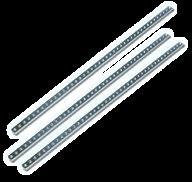
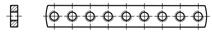
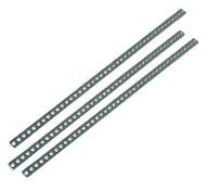
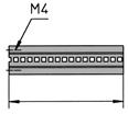
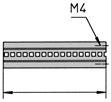
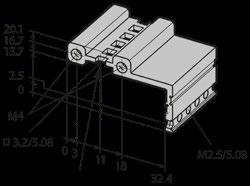
Tapped Strips M2.5, 2 x 6 mm
› M2.5, 2 x 6 mm
› Steel, galvanised, passivated
M2.5 4 HP Steel, zinc-plated 61-483
M2.5 8 HP Steel, zinc-plated 61-475
M2.5 10 HP Steel, zinc-plated 61-436
M2.5 15 HP Steel, zinc-plated 61-476
M2.5 18 HP Steel, zinc-plated 61-477
M2.5 21 HP Steel, zinc-plated 61-459
M2.5 27 HP Steel, zinc-plated 61-486
M2.5 28 HP Steel, zinc-plated 61-458
M2.5 32 HP Steel, zinc-plated 61-463
M2.5 40 HP Steel, zinc-plated 61-465
M2.5 42 HP Steel, zinc-plated 61-464
M2.5 47 HP Steel, zinc-plated 61-461
M2.5 60 HP Steel, zinc-plated 61-466
M2.5 63 HP Steel, zinc-plated 61-469
M2.5 81 HP Steel, zinc-plated 61-467
M2.5 84 HP Steel, zinc-plated 61-468
M2.5 2200 mm Steel, zinc-plated 61-532 Description Material Part-No.
M2.5 43 HP Steel, zinc-plated 61-588
M2.5 64 HP Steel, zinc-plated 61-587
M2.5 85 HP Steel, zinc-plated 61-568
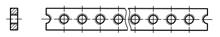
Tapped Strips M2.5, 1.8 x 5 mm
› M2.5, 1.8 x 5 mm
› Steel zinc-plated, passivated
M2.5 10 HP Steel, zinc-plated 61-470
M2.5 18 HP Steel, zinc-plated 61-478
M2.5 27 HP Steel, zinc-plated 61-479
M2.5 42 HP Steel, zinc-plated 61-471
M2.5 46 HP Steel, zinc-plated 61-460
M2.5 63 HP Steel, zinc-plated 61-472
M2.5 81 HP Steel, zinc-plated 61-473
M2.5 84 HP Steel, zinc-plated 61-474
M2.5 2200 mm Steel, zinc-plated 61-534
M2.5 43 HP Steel, zinc-plated 61-584
M2.5 64 HP Steel, zinc-plated 61-585
M2.5 85 HP Steel, zinc-plated 61-586

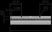
Tapped Strips M3, 2 x 6 mm
› M3, 2 x 6 mm
› Steel zinc-plated, passivated
M3 10 HP Steel, zinc-plated 61-435
M3 28 HP Steel, zinc-plated 61-456
M3 42 HP Steel, zinc-plated 61-454
M3 63 HP Steel, zinc-plated 61-455
M3 81 HP Steel, zinc-plated 61-450
M3 84 HP Steel, zinc-plated 61-453
M3 427.78 mm Steel, zinc-plated 61-242-443
M3 443.02 mm Steel, zinc-plated 61-242-428
Ø 7 (M2.5) POM 61-088

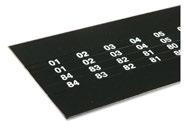
› Numbering of HP-steps
› Mounting onto front extrusions
› Black plastic, PVC
› Numbering white
› Self-adhesive
Scope of delivery:
› 1 label strip, consisting of 4 single tapes
HP
HP
66-901-21 81 HP ABS 66-901-22 84 HP ABS 66-901-23
Titel Titel Titel
Titel zweite Zeile
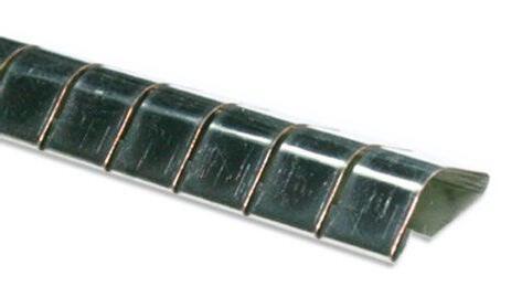
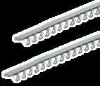
For effective EMC and HF protection
Das Nonsequam ab idit quam fuga. Nem quate comnihitis quia sit, abore volo earumqu odiorem porecum nimus aut qui aut et, nonse volupta tempeli busani nobis et aliati numque post, ut ute cus vitiatur antium volupta nullestiis magnisc ientiore estrum eatur, ipic tenimet occus natios ma dendict otatece pereror ad ma ate aut fuga. Musam andae pos et hitasit idelit, unt.
The use of EMC and HF gaskets effectively protects sensitive electronics from electromagnetic or high-frequency interference. They also insulate the propagation of effects and interference from inside housings and subracks and support a trouble-free process to meet regulations and standards for technical devices.
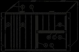
Contact Springs (A)
› Stainless steel
› Side front panel to end side panel
› EMC dividing extrusion 66-266
› Self-adhesive
2
3
6
4
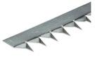
EMC Contact Strips (A)
› BeCu galvanised
› Side front panel to end side panel
› Self-adhesive
The respective letter indicates the typical position of the gasket in an enclosure. The letters are used below to indicate where the gaskets should be used.
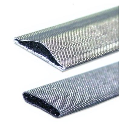
EMC Gaskets (A and B) Stainless Steel
› Stainless Steel
2
3
4
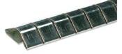
› Polyurethane foam core
› Conductive fabric (Ni+Cu plated)
› Self-adhesive
› BeCu galvanised
› For part front panels
› Self-adhesive
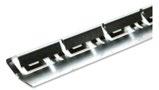
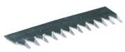
EMC Contact Strips (C)
› BeCu galvanised
› For front panels, fixing on extrusion
› Self-adhesive
Scope of delivery: 2 EMC contact strips
EMC Contact Strips(D)
› BeCu galvanised
› Self-adhesive
› Scope of delivery: 1 EMC Contact Strips
EMC Contact Strips
› For fixing on flat front panels
› Self-adhesive
› For EMC-sealing from extrusion to extrusion plates
› Firmer securing of non-screwed extrusion plates, Conductive sealing
Scope of delivery: 1 sealing gasket conductive
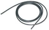
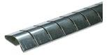
HF Gasket
› Neoprene foam core
› Aluminium cover
› Self-adhesive
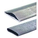
HF Gaskets (A)
› D-shaped
› Polyurethane foam core
› Conductive fabric (Ni+Cu plated)
› Self-adhesive
HF Spring (C)
› Stainless Steel
› Snapped-in on the extrusion
› Scope of delivery: 2 Pcs. HF spring 84 HP
1
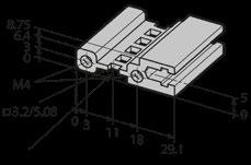
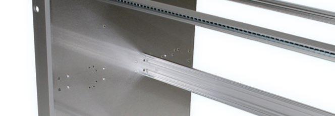
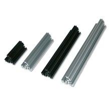
Custom-made Aluminium profiles for the construction of subracks and enclosures
Das Nonsequam ab idit quam fuga. Nem quate comnihitis quia sit, abore volo earumqu odiorem porecum nimus aut qui aut et, nonse volupta tempeli busani nobis et aliati numque post, ut ute cus vitiatur antium volupta nullestiis magnisc ientiore estrum eatur, ipic tenimet occus natios ma dendict otatece pereror ad ma ate aut fuga. Musam andae pos et hitasit idelit, unt.
As a leading provider of subracks, Elma offers a large range of profiles for a wide variety of applications. 19" systems according to various standrads can be set up easily. With our offer of special profiles individual solutions or the construction of complete enclosures are possible.
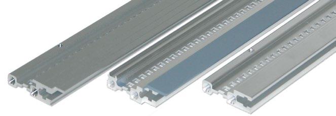
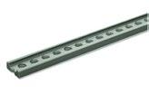
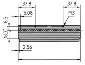
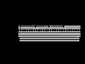
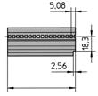
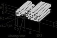
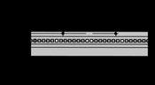
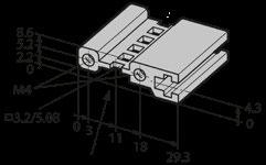
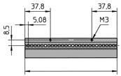
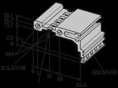
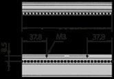
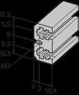
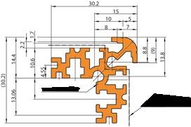
Front Extrusion 66-111, IEC
› For sub racks and cases front
› Accepts 2 x 6 mm tapped strips
Scope of delivery:
› 1 front extrusion without assembly material
Montageseite Kartenführung
Card Guide Mounting side
Height Divider Right:
EMC Versions: Height Divider Left:

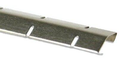
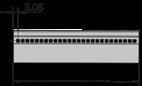
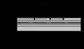
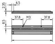
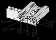
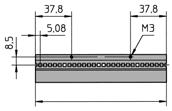
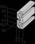
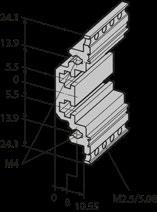
Front Extrusion 66-112
› For sub racks and cases front, without protrusion
› Accepts 2 x 6 mm tapped strips
Scope of delivery:
› 1 1 front extrusion without assembly material
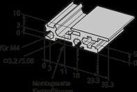
Front Extrusion 66-112, IEC
› For Magic-Kit 11 according to IEC/EN standard
› Accepts 2 x 6 mm tapped strips
Scope of delivery:
› 1 front extrusion without assembly material
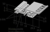
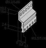
Horizontal Front Sub Division Extrusion 66-245, IEC
› Card guide can be applied
› Accepts 2 x 6 mm tapped strips
Scope of delivery:
› 1 front double extrusion IEC-special without assembly materiall
Front Extrusions
Horizontal Front Sub Division Extrusion 66-243, IEC
› Card guides cannot be used
› Accepts 2 x 6 mm tapped strips
Scope of delivery:
› 1 front double extrusion IEC-special without assembly material
Front Extrusion 66-282, IEC
› For Stylebox 15 Smart
Scope of delivery:
› 1 Front extrusion without assembly material
Front Extrusion 66-677, IEEE
› Front separation extrusion according to IEEE standard
› Accepts 2 x 6 mm tapped strips
Scope of delivery:
› 1 Front extrusion without assembly material for Spirit-Kit 11 (IEEE):
For Systemkit 12K and Stylebox 15 according to IEEE standard:
* EMC protection
Front Extrusions
Front Extrusion (robust Version) 66-678, IEEE
› Front separation extrusion acc. IEEE standard
› Accepts 2 x 6 mm tapped strips
Scope of delivery:
› 1 front extrusion without assembly material
Version for Systemkit 12K according to IEEE standard
Front Extrusion 66-666, IEEE
› For Spirit-Kit 11 according to IEEE standard
› Accepts 2 x 6 mm tapped strips
Scope of delivery:
› 1 front extrusion without assembly material
Front Extrusion 66-281, IEEE
› For Stylebox 15 standard according to IEEE
› Accepts 2 x 6 mm tapped strips
Scope of delivery:
› 1 front extrusion without assembly material, powder-coated
* EMC protection
InnenlängsprofileInternal
Horizontal Front Sub Division Extrusion 66-240, IEEE
› Card guide can be applied
› Accepts 2 x 6 mm tapped strips
› Ejector / Injector Handles IEEE can be fixed
Scope of delivery:
› 1 front double extrusion IEEE special without assembly material
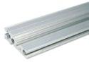
Extrusion 66-242, MicroTCA
› Accepts 2 x 6 mm tapped strips
Scope of delivery:
› 1 MicroTCA extrusion without assembly material
Internal Extrusion 66-193 for Insulated Backplane Mounting
› For mounting backplanes in sub racks
› Accepts 1.8 x 5 mm tapped strips
Scope of delivery:
› 1 extrusion without assembly material
Standard Versions:
EMC Versions:
Versions for Unibox 14:
› For mounting backplanes without an insulating strip
› Accept 1.8 x 5 mm tapped strips
Scope of delivery:
› 1 extrusion without assembly material Standard Versions:
› Standard extrusion for mounting supplementary edge connector extrusions in sub racks and cases
› Accept 2 x 6 mm tapped strips
Scope of delivery: › 1 extrusion without assembly material
Internal Extrusion 66-138 for Card Guides
› For mounting card guides
› For rear I/O applications
› Tapped strip not required
Scope of delivery:
› 1 extrusion without assembly material
Standard Versions
Height Divider Left: Height Divider Right:
Standard Internal Extrusion 66-140
› Edge connector extrusion according to IEC60603-2
Scope of delivery:
› 1 edge connector extrusion without assembly material
EMC protection
Standard Internal Extrusion 66-137
› Edge connector extrusion according to IEC60603-2 with groove
› Accepts 1.8 x 5 mm tapped strips
Scope of delivery:
› 1 edge connector extrusion without assembly material
Standard Versions:
Double Extrusion 66-192 for Insulated Backplane Mounting
› For mounting backplanes, matches 66-193, 66-288
› For use with insulating strips
› Accept 2 x 6 mm tapped strips
Scope of delivery:
› 1 extrusion without assembly material
Double Extrusion 66-195 for Conductive Backplane Mounting
› For mounting backplanes without insulating strips
› Matches 66-194, 66-289, 66-290
› Accept 2 x 6 mm tapped strips
Scope of delivery:
› 1 extrusion without assembly material
Double edge connector extrusion 66-190
› Double edge connector extrusion IEC60603-2
› Matches 66-137 and 66-140
› Accepts 2 x 6 mm tapped strips
Scope of delivery:
› 1 double edge connector extrusion without assembly material
Edge Connector Extrusion 66-145
› For use with standard extrusion 66-144
Scope of delivery:
› 1 Edge connector extrusion without assembly material
Assembly Material:
› For use with extrusions for backplanes 66-193
Scope of delivery:
› 1 edge connector extrusion without assembly material
Assembly Material:
Insulating Strips 66-901
› In use with extrusions 66-112, 66-192, 66-193, 66-288
› Plastic grey
Scope of delivery:
› 1 insulating strip without assembly material
Mounting with Insulation Strips:

Height Extrusion 19" 66-175
› 19" height extrusion type 11
› For standard side panel 2 mm
Scope of delivery:
› 1 height extrusion without assembly material
6
Height Extrusions 19" 66-275
› 19" height extrusion type Systemkit 12K
› For standard side panel 2 mm Scope of
1
Height Extrusion 66-174
› Height extrusion type 11
› For standard side panel 2 mmm
Scope of delivery:
› 1 height extrusion without assembly material
6
8 354.8 13.96 66-174-28
9 399.2 15.71 66-174-29
10 443.7 17.47 66-174-30
12 532.6 20.96 66-174-32
Height Extrusions 66-274
› 19" height extrusion type Systemkit 12K
› For standard side panel 2 mm
› Shaped for direct mounting of the EMC-gasket 81-062-xx
Scope of delivery:
› 1 height extrusion without assembly material
6
9 399.2 15.71 66-274-29
Height Extrusions with Cut-out for Telescopic Rails:
› Cut-out for telescopic rails
3
4
6
EMC protection
Height Extrusion 66-173
› Height extrusion for Unibox 14
› Slim version with or without fixing hole for handle
Scope of delivery:
› 1 height extrusion without assembly material
2
3
4
5
6
Height Extrusion 19" 66-179
› With or without fixing hole for handle
› 19" height extrusion for Unibox 14 / 84 HP
Scope of delivery:
› 1 height extrusion without assembly material
2
fixing hole for handle
fixing hole for handle
7
8
9
Height Divider Extrusions 66-115 | 66-107
› Divider extrusion front
Scope of delivery 66-115:
› 1 height extrusion without assembly material
Scope of delivery 66-107:
› 1 height extrusion without assembly material
Height Divider Extrusion 66-266
› EMC divider extrusion
Scope
EMC Contact Spring:
› Stainless steel
› Side front panel end side panel
› EMC dividing extrusion 66-266
Height Divider Extrusion 66-116
› Divider extrusion rear
Scope of delivery:
› 1 height extrusion without assembly material
Depth Extrusion 66-177
› Depth extrusion for universal sub rack Unibox 14
Scope of delivery:
› 1 depth extrusion without assembly material
20.96 66-177-26
Depth Divider Extrusion 66-176
› Depth divider extrusion for universal sub rack Unibox 14
Scope of delivery:
› 1 depth extrusion without assembly material
532 20.94 66-176-26

› To build up customised solutions
› For 6 U cassettes and modules type 23
Scope of delivery:
› 1 depth extrusion without assembly material
› To build up customised solutions
› For 3 U type 23 cassettes and modules
Scope of delivery:
› 1 side wall extrusion without assembly material
Card Guide Extrusion, 66-122, IEC
› For card thickness: 1.6 mm / 0.06"
› Card guide extrusion, single, clear anodised
› ESD clip not usable
Scope of delivery:
› 1 extrusion without assembly material
End Feet:
Card Guide Extrusion 66-452, IEEE
› For card thickness 1.6 mm / 0.06" and 2.0 mm / 0.08"
› Extrusion: Aluminium
› End feet: Plastic UL94 V-0
8.66 66-452-25
11.02 66-452-30 340 13.38 66-452-35
53.14 66-452-14
End Feet:
Miscellaneous Extrusions
Card Guide Extrusion 66-453, IEEE
› For card thickness 2.4 mm / 0.094"
› Extrusion: Aluminium
› End feet: Plastic UL94 V-0
Hinge Extrusion 66-230
› To build up customised hinged front panels
Hinge Extrusions for Top/Bottom-Hinged Front Panels:
Assembly Material incl. Hinge Parts for Top/Bottom-Hinged:
Hinge Extrusions for Side-Hinged Front Panels:
3
8
Assembly Material incl. Hinge Parts for Side-Hinged Front Panels:
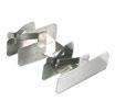
Contact Bracket For EMC Front Panels
Scope of delivery:
› Set of 2 brackets
› 4 countersunk screws M2.5 x 6
2
3
4

EMC Contact Spring:
› Stainless steel
› Side front panel end to side panel
› Mounted on side panel of case
› Self-adhesive
› For 4 HP to 14 HP
› EMC front panel extrusion according to IEEE standard HP
5
6
12 HP 60.6 2.38 1350 53.15 66-522-19
14 HP 70.8 2.79 1350 53.15 66-534-19
› As used in Varietybox 35
› Accept 2 x 6 mm tapped strips
› Without assembly material
Scope of delivery:
› 1 corner extrusion
to complete your 19'' system
estrum eatur, ipic tenimet occus natios ma dendict otatece pereror ad ma ate aut fuga. Musam andae pos et hitasit idelit, unt.
19'' systems need accessories for an individual expansion: Front panels, card guides, ventilation solutions or special components. Elma offers not only the components for your 19'' system but also a complete assembly service for your ready-to-use installation.
Front/Rear Panels 19", Solid, Anodised
› Aluminium 3 mm
Scope of delivery:
› 1 Front Panel
1 U 43.6 1.71 20-101
2 U 88.1 3.46 20-102
3 U 132.5 5.21 20-103
4 U 177.0 6.96 20-104
5 U 221.5 8.72 20-105
6 U 266.0 10.47 20-106
7 U 310.5 12.22 20-107
8 U 355.0 13.97 20-108
9 U 399.0 15.70 20-109
10 U 443.5 17.46 20-110
12 U 532.5 20.96 20-112
Front/Rear Panels 19", Solid, Powder Coated
› Aluminium 3 mm
› Rear conductive
› Lightgrey RAL 7035
Scope of delivery:
› 1 Front Panel
1 U 43.6 1.71 20-101-30
2 U 88.1 3.46 20-102-30
3 U 132.5 5.21 20-103-30
4 U 177.0 6.96 20-104-30
6 U 266.0 10.47 20-106-30
Other colours and heights on request
Fan Front Panels 19"
› Aluminium 3 mm
› Clear anodised
Scope of delivery:
› 1 Front Panel
1
2
3
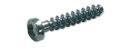
Assembly Material
› For mounting front panels in cabinets
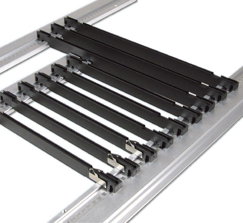
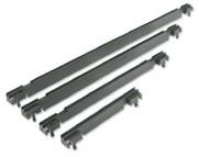
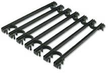
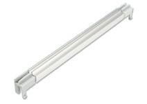
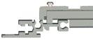
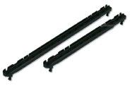
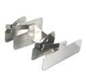
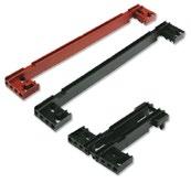
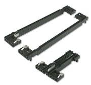
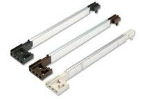
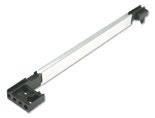
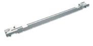
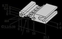
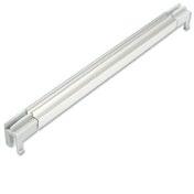
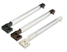
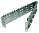
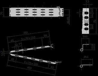
Despite their rugged construction, these are among the slimmest telescopic rails available on the market. All types can be locked in the extended position and are fitted with a quick release latch. The load carrying capacity of one pair is 60 kg.
› Extremely slim, overall width only 6 mm
› New type of corrosion-proof surface with high sliding properties
› No additional lubrication necessary
› Little frictional resistance with heavy loads
› Self-unlocking plug-in function
› Load capacity up to 60 kg/132 lb (US) / pair
› Ease of assembly
› No milling of front vertical extrusion necessary
› Suitable for all heights
Scope of delivery:
› 2 telescopic rails
› Mounting brackets
› Assembly materal for mounting into cabinet and on module
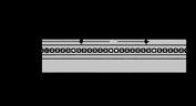
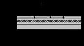
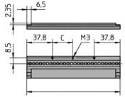
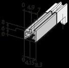
Drawings
› Showing a 60 kg rail

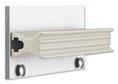
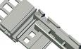
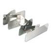
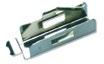
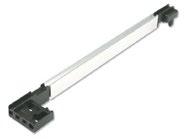
Cable Carrier
The cable carrier can be easily installed and detached by removing the hinge bolt. It is mounted on the rear vertical section
Scope of delivery:
› 1 Cable Carrier
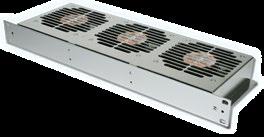
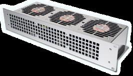
› The fan modules are designed for vertical ventilation of 19" cabinets.
› Modules for depths of 160 mm and 220 mm have 3 fans
› These are arranged in an optimum configuration to ensure cooling of the PCBs over the entire width of the rack
› Fan modules with 19" front panels are designed for use in 19" racks and cabinets
› They can be run in and out on supporting rails
› The modules have a 3-pole appliance inlet for connection to the mains
Fan Modules Vertical 19"
› 230V/50Hz (115 V on request)
Scope of delivery:
› 1 fan module 19", assembled, ready for connection
Assembly Material
Fan Modules Horizontal 19"
› 230 V/50 Hz (115 V on request)
Scope of delivery:
› 1 fan module, assembled ready for connection
2
Assembly Material:
› The fan module is designed for vertical ventilation of a sub rack or desktop case.
› Modules for depths of 160 mm and 220 mm have 3 fans.
› These are arranged in an optimum configuration to ensure cooling of the printed PCBs over the entire width of the rack.
› Fan modules with 84 HP front panels (with on/off switch) are for mounting in withdrawable units and desktop cases acc. to DIN 41494, part 5, being run in and out on card guides.
› An AMP socket is used for the mains connection
› 230V/50Hz (115 V on request)
Scope of delivery:
› 1 fan module 84 HP, assembled, ready for connection
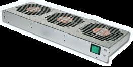
Assembly Material:
› For mounting fan module in housing
› Set of 10 screws with screw retainer
Power Supply AMP connector, "M" series, 14 pole (pin), Standard in fan modules 84 HP
The fan module is inserted in the case or rack on card guides. The AMP connector on the inserted fan module makes contact with the socket mounted on the rear extrusion.
Scope of delivery:
› 1 handle
› Per handle 2 screws are needed
1
Assembly Material:
Cross recessed cylinderhead earthing screw M4 x 10
Torx roundhead earthing screw M4 x 10, size T20 5443-01
Cross recessed countersunk screw M4 x 10 5342-10
Torx countersunk screw M4 x 10, size T20 5470-26
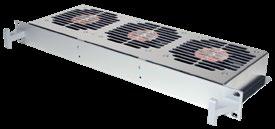
› The front filter is fastened to the front panel of the fan body or the fan front panel 2 U / 84 HP using two captive screws
› The filter mat can be re-used after washing in water with a temperature of up to approx. 40°C
› Replacement filter mats can be ordered as spare parts
Scope of delivery:
› 1 filter cradle, aluminium, clear anodised
› 1 filter mat, polyester
› 1 filter mat support, steel galvanised
› 1 set of assembly material
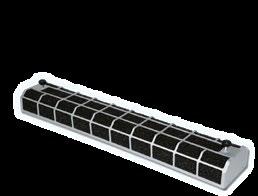
› The filter set is fastened to the pressure side of the fan body by means of two quick-release fasteners
› The filter mat can be regenerated by washing in water at approx. 40°C
› The filter set can only be used wiht 2 U / 19" fan modules
› Replacement filter mat on request
Scope of delivery:
› 1 Filter catch, steel
› 1 filter mat, polyester
› 2 fastening elements
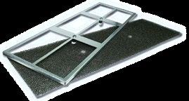
› Brushless
› Sealed ball bearings
› Polarity and electronic locked rotor protection (autorestart)
› Air exhaust in over struts (can be mounted directly on a perforated front panel)
› Connector 2.8 x 0.5 (except fan with speed sensor)
› Fan case and wheel plastic UL94 V-0
› Operating temperature –20 °C to +70 °C
› CE, UL, CSA, VDE standard
› Life expectancy L10 = 70 000 hours at 40 °C
› Special configuration with speed sensor
› Split-pole motor
› Sealed ball bearings
› Impedance protection resp. integrated thermal switch
› Connector 2.8 x 0.5
› Air exhaust in over struts (can be mounted directly on a perforated front panel)
› Fan case: aluminium
› Fan wheel: plastic UL94 V-0
› Operating temperature –40 °C to +70 °C
› CE, UL, CSA, VDE standard
› Life expectancy L10 = 50 000 hours at 40 °C)

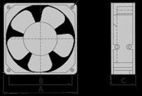
Fan Mounting Panels
› The fan-mounting panel are designed for easy fitting of axial-flow fans for vertical and cross-flow ventilation of 160 mm deep cards in cases and modules.
› The panels are fixed to the horizontal extrusion using 6/4 screws (M3x10)
› Aluminium 1.5 mm, raw
Scope of delivery:
› 1 fan mounting panel
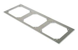
Fan Mounting Panels for Cross-flow Ventilation (Horizonal Mounting Kits)
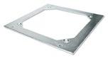
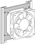
Assembly Material
Fan Front Panels
Fan Front Panel 84 HP for Vertical Ventilation
› Fan front panels are flat, perforated and designed to ensure an optimum air flow rate
› Available with or without switch cut-out (switch opening 1 U = 12.3 x 27.2 mm / 2 U = 22 x 30.6 mm)
› Aluminium 2.5 mm, clear anodised (non-conductive)
Scope of delivery:
› 1 perforated fan front panel
On-Off Switch:
› Black body, plastic
› 2 poles, 250V, 16A
› Quick-connect terminal 6.3 x 0.8 mm
› Cut-out for 4426-00: 22 x 30.6 mm (0.87" x 1.20") Cut-out others: 12.3 x 27.2 mm (0.48 x 1.07")
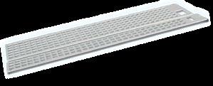


switch, without signal light
Fan Front Panel for Horizontal Ventilation
› Aluminium 2.5 mm, clear anodised (non-conductive)
Scope of delivery:
› 1 perforated fan front panel


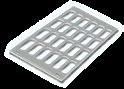
Fan Front Panels for Direct Fan Mounting
› Aluminium 2.5 mm, clear anodised (non-conductive)
Scope of delivery:
› 1 perforated fan front panel
Assembly Material for Fan Mounting:
› Set of 10 screws
› With screw retainer
› Per front panel 4 screws are needed


Air Baffle Covers
› When 84 HP fan modules are used, an air baffle cover can be fitted to regulate the cooling air flow and ensure maximum dissipation of the heat generated by the electronic devices.
› The air baffle cover is fixed to the internal extrusions by means of 4 screws.
› The air supplied to the PCBs (160 and 220 mm deep) above the baffle plate is regulated by opening or closing the vanes.
› To optimise the cooling air flow, a cover panel can be fitted to the back of the fan assembly. This will prevent internal air circulation)
Scope of delivery:
› 1 air baffle cover
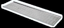
Assembly Material:

Elma Electronic AG, Switzerland
Hofstrasse 93
CH-8620 Wetzikon
T: +41 44 933 41 11
F: +41 44 933 42 15 sales@elma.ch
Elma Electronic GmbH, Germany
Stuttgarter Strasse 11 D-75179 Pforzheim
T: +49 7231 97 34 0 F: +49 7231 97 34 97 info@elma.de
Elma Electronic France SA 16 rue de Hannah Arendt
Parc des Forges
F-67200 Strasbourg
T: +33 38 56 72 50 sales@elma-electronic.fr
Elma Electronic UK Ltd.
Solutions House
Priory Business Park
Fraser Road
Bedford MK44 3BF
Great Britain
T: +44 1234 838822
F: +44 1234 836650 sales@elma.co.uk
Elma Electronic Romania SRL Chisoda, DN 59 km8 + 550m
RO-307221 Judetul Timis
T: +40 374 480 400
F: +40 256 249 820 sales@elma.ch
Elma Electronic Israel Ltd. 34, Modi'in St., I.Z.Sgula IL-49271 Petach-Tikva
T:. +972 3 930 50 25
F: +972 3 931 31 34 sales@elma.co.il
Elma Electronic Inc., USA 44350 S. Grimmer Blvd Fremont, CA 94538, USA
T: +1 510 656 3400
F: +1 510 656 3783 sales@elma.com
Optima Stantron, USA 2305 Newpoint Parkway Lawrenceville, GA 30043, USA
T: +1 770 496 4000
F: +1 770 496 4026 sales@elma.com
Elma Electronic Private Ltd., India Green Arch 3rd Phase 1st Main
J.P. Nagar Bangalore 560078 sales@elma.com
Elma Electronic Technology (Shanghai) CO., Ltd., China No. 11 Building, No198 Chang Jian Road, Bao Shan District CN-200949 Shanghai
T: +86 21 5866 5908 F: +86 21 5866 5918 sales@elmachina.com
Elma Asia Pacific Pte. Ltd., Singapore 8 Ubi Road 2 # 07-14 Zervex Building SG-408538 Singapore
T: +65 6479 8552
F: +65 6479 8662 sales.elmaap@elma.com