Research Report 2020
2.3
Institute of Computational Physics
3-D Model of Water and Heat Transport in PEMFCs During Evaporative Cooling and Humidification
Evaporation in gas diffusion layers with hydrophilic lines have been shown to allow for simultaneous cooling and humidification in proton exchange membrane fuel cells (PEMFCs). The objective of this study is to enhance our understanding of evaporative cooling and humidification using numerical modeling. We investigate the dominant heat and water transport processes and analyse the local sensitivity of the model output to changes in operating conditions and model parameterizations. Contributors: Partner(s): Funding: Duration:
R. Herrendörfer, J. O. Schumacher SCCER Mobility: Swiss energy competence center: Efficient technologies and systems for mobility, Paul Scherrer Institute (PSI) Innosuisse 2014–2020
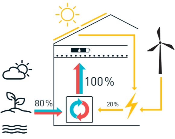
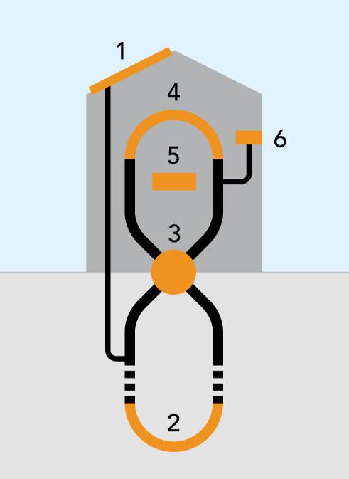
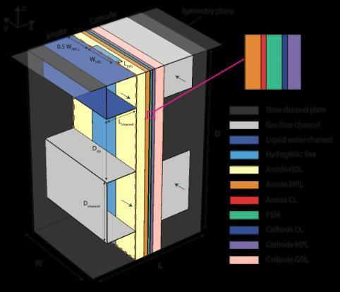
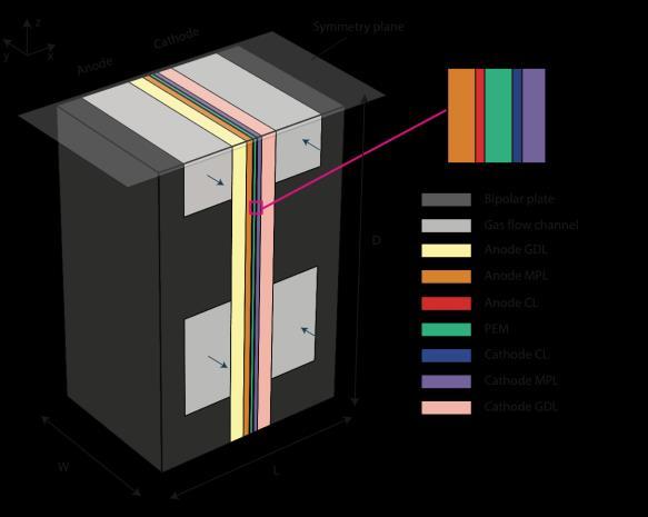
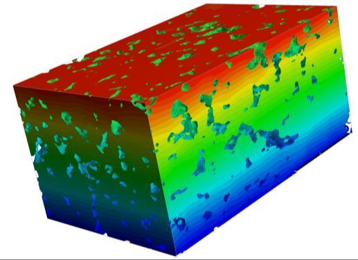
Evaporative cooling is a promising concept to optimize the water and heat management in PEMFCs and thereby to reduce costs. It is based on the vaporization of water directly inside cell to provide simultaneous humidification and cooling. The PSI developed a concept that is solely based on modifications of the anode gas diffusion layer by locally changing the wettability from hydrophobic to hydrophilic. Experimental work at PSI has demonstrated the usability of this concept [1]. At the ICP, we have developed a 3-D, macro-homogeneous, nonisothermal two-phase model to investigate the dominant heat water transfer processes during evaporative cooling and humidification in a single-cell PEMFC (Figure 1). We solve for the transport of gas, liquid water, dissolved water, heat, electrons and protons.
the has
and Figure 4: 3-D model setup. Anode flow field with one gas and liquid water channel, respectively, a cathode flow field with two gas channels. The membrane electrode assembly includes the hydrophobic anode gas diffusion layer with one hydrophilic line.
In the reference model, which was adapted to the experimental setup at PSI in terms of operating conditions and properties, most of the water vapour generated along the hydrophilic lines are transported to the outlet of the anode gas flow channel and only a small fraction of water vapour diffuses to cathode side (Figure 2a-b). While most of the evapoFigure 5: Water management at anode side (top) and cathode side (bottom). (a) Relative ration takes place at the interhumidity (RH). (b) Evaporation rate and streamlines of water vapour flux. (c) Streamlines of face between gas flow channel liqud water flux and dissolved water flux, water content dissolved in the membrane (). and hydrophilic line, a part occurs at the interfaces between the hydrophilic line and hydrophobic GDL (Figure 2b). The water content dissolved in the membrane is the highest on the anode side of the membrane below the hydrophilic line and liquid water channel. References: [1] Cochet, M., A. Forner-Cuenca, V. Manzi, M. Siegwart, D. Scheuble, and P. Boillat.Fuel Cells 18 (5): 619–26, 2018.
Zurich University of Applied Sciences
17
www.zhaw.ch