Mitsubishi
6D16TLEA Diesel Engine Engine Workshop Manual (for Tadano Crane use)
FOREWORD
ThisShop ManualispublishedfortheinformationandguidanceofpersonnelresponsibleformaintenanceofMitsubishi 6D16TLEA diesel engine, and includes procedures for adjustment andmaintenanceservices.
Weearnestlylookforwardtoseeingthatthismanualismade fulluseofinordertoperformcorrectservicewithnowastage.
For more details, please consult your nearest authorized Mitsubishidealer ordistributor.
Kindlynotethatthespecificationsandmaintenanceservice figuresaresubjecttochangewithoutpriornoticeinlinewith improvement which willbe effected from time to time in the future.
Mitsubishi 6D16TLEA engine parts contact: email: engineparts2@gmail.com
Phone: 269 673 1638
Text: 269 760 8652
HOW TOREADTHISMANUAL GENERAL .....................·lim ENGINE........................·ID LUBRICATION..................·IE FUELAND ENGINE CONTROL ..·IE COOLING ......................·Ill INTAKEAND EXHAUST .........·Im ELECTRICALSYSTEM ..........·ml
GROUP INDEX
Notes: parts phone 269 673 1638
HOW TO READ THIS MANUAL
HOW THIS MANUAL IS COMPILED
GENERALEXPLANATION OF THIS MANUAL
TERMS AND UNITS
........................ .... ii
..........;........ iii
.......................................... vii
HOW TO READ THIS MANUAL
HowThis Manual Is Compiled
• This manual is compiled by classifying various systems into certain groups.
• Each group containsspecifications; troubleshooting; maintenanceservicestandards; 0tighteningtorque; cD.lubricant, fluid and sealant; � special tools; and service procedure.
• Page enumeration is independent by every group where firs page is always 1.
00
General specifications, engine No. andnameplate, precautionsformaintenanceoperations, table ofstandard tighteningtorques
54
starter, preheatingsystem, engine startsystem, automaticstop system 61
Group Group denomination Contents No.
General
11 Engine Engine body 12 Lubrication Lubricationsystem 13 Fuelandengine control Fuel system 14 Cooling Coolingsystem 15 Intake and exhaust Intake
21 Clutch Clutch
and exhaustsystem, turbocharger, intercooler
proper,bearingcase
Electrical system Alternator,
Specialequipment Air
II
compressor, pressure governor
General Explanation of This Manual
• Specifications
Particularsrelative tomaintenanceservice aremade.
• Structure and operation
(1) Regardingconventionalequipment, descriptions are madeinbrief.
(2) Regardingnewequipment, descriptions ofsystemandoperatingcondition aremade indetail.
• Troubleshooting
Symptomsof troublesand possible causesare describedcomparatively.
• Inspection and adjustment mounted in vehicle
Descriptions are made regarding inspectionandadjustment ofunits mounted in vehicle.
• Service procedure
Inprinciple,anexplanationisgivenatthespreadtitlepagesothattheserviceprocedurecanbeunderstood.Servicingpoints areexplained as a supplementary explanation.
Regardingthe design ofthis manual
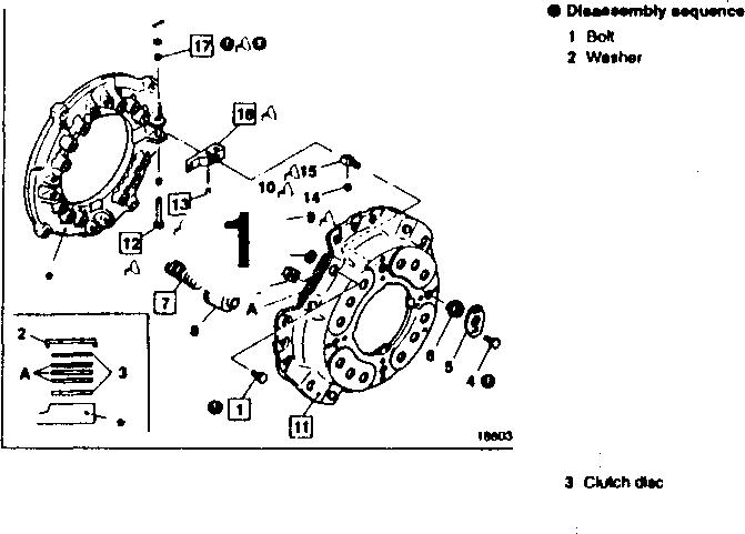
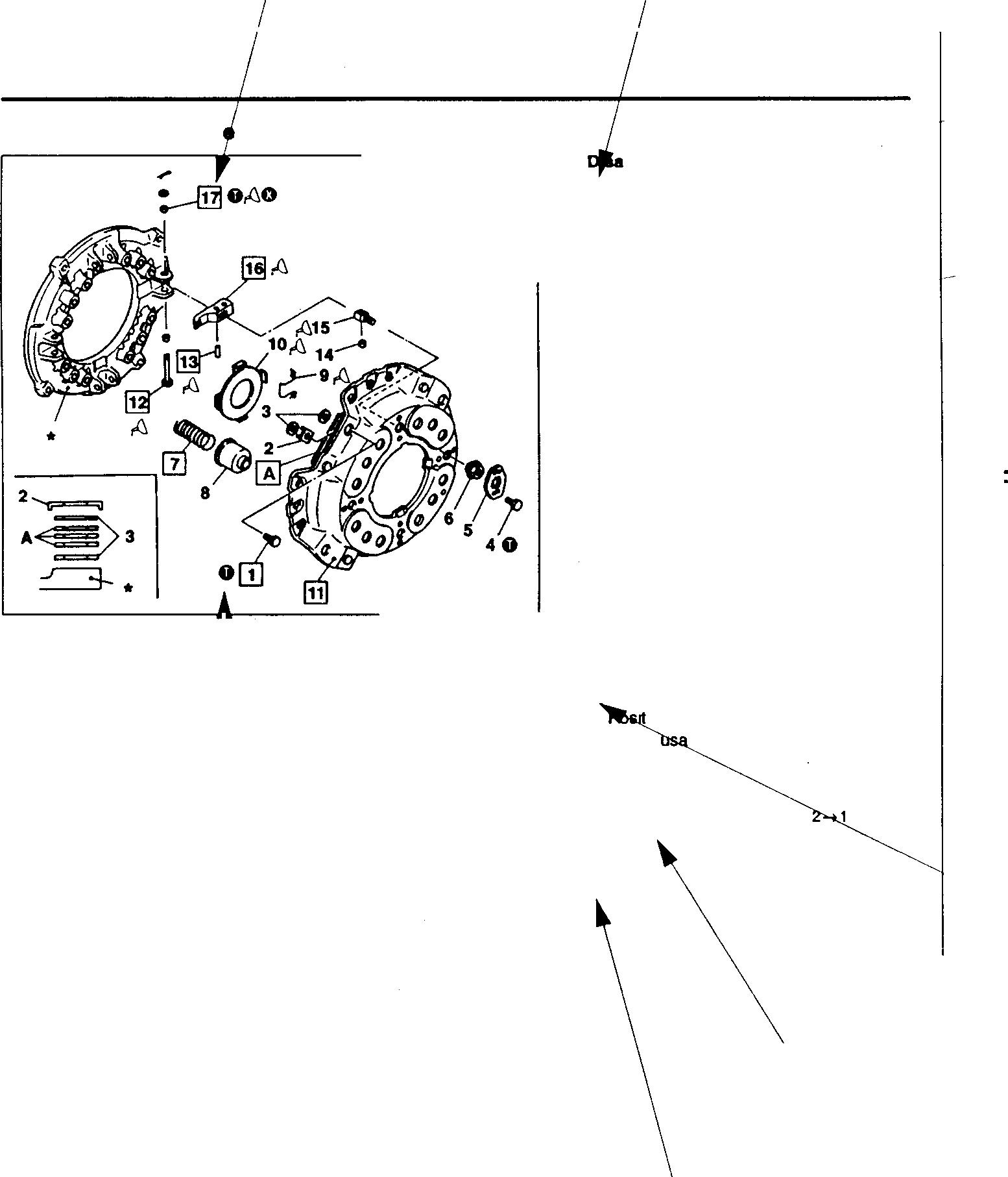
CLUTCH BODY PreHUNPlateandLeverA...mbly
:�1a
7;.;ldM�

1 Illustrationfordisassemblyandassemblyorremovalandinstallation: 3-D explodedviewofcomponentparts is displayed.

Names of parts show an exampleofthe disassembly (removal) sequence.
Whentheassembly (installation)sequencediffersfromthedisassembly (removal) sequence, anexampleof the assembly (installation) sequence is shown.
Service standards areshown collectively, classified by location.
Tighteningtorques areshowncollectively, classified by location.
Pointsof lubricant, fluid andsealantapplication areshown collectively, classified by location.
Special toolsto beused areshowncollectively, classified by location.
When itisconsidered hardtounderstandtheserviceprocedure, justby the foregoing description, a supplementary description of theservice procedureis given.
3Wast.•
7Pre, /[/Ort IPreuura91)MQeap •Aelumtpnng 10fw!N"i.vetplala 11Clulchoov.r 12 AelNMlrh'erpin usuppo,1...,.,p1n ,....,.,. 1ISIJl)l)O(I...,., 1IAelMNlevw 17ZP,...,nplale&i.-uMnt,ly UP2M2 ·-.,,,.._, A•Poelllotllngpin{lll2�) 0:Non---.blepart 1,1....ir-·1b....1....,----,...,....,...2...., U-015➔13�llll;dutch,..._Q Unll mm Standllrdvlllus (B..lcdlllmM.,.,nll) ,...1,A c-....�......bo11ndllrt,p�
.., -�,......,�...,.�..=,,-+--�...,=.=,.,,� .,.---+-�--+2 21,.,....,...f7'71,g1J " ·-10 c...,._i. -pwianc111u1Nng I1oiooe1oo1e 10 "--'--. ---t----,,.-..-,---<----<--0Tlghl.nlngtorque Uni!Nml•vtm) L�1ton Slurp_(_:::;; o 3 ____,__....._""_�:=••"""'"�••�• ___,_I_"'"'�::...=-•"'___,I 4 Boll(NCIIMgloc:t,plak _ ll.llo7fl!0.II008) _ ,..., . 10.11 SM,g_,_GII,_. 12,17 ...........al._ 13,14 ...,._,_"'"-"PO· iJ Special tools '�""' Tool-and� 21 LOCTITE,12 ,..,_.., PortNo -11 �- � MHOl10&1 AMlow'llland.......,dduld,� 5 "�""= " �- .��T ...,.,,., �..........."-"".,._ \ 111• ♦-�{ .� (1][!Ja--..........,,lloll.....,,,.... ·--�-----.....�--�p(lrt A.ShppllN 01119 �: 11 OIJW ill.......,...,._..,.. 11��11'hu�...-,,d.��-.het"Aoon. epordng1othl'ln'IIU!lolr.g,n:tin..��--p,aau,e pi...n�..,mg1. ----
��
1a. 1b. 2 3. 4 ...... 5. 6........
iii
HOW TO READ THIS MANUAL
1. Illustrationfor disassembly and assembly or removal and installation
This shows thattheappropriateserviceprocedureis describedin thetext.
CLUTCH BODY
Pressure Plate and L ver Assembly
01276
This shows the key No. of the part. In the text, this No. isreferredtouniformlythroughout.
• aHmblyaequence
Strapbolt
Washer
Washer
Bolt
Lock plate
Supportnut ---------
Pressuresp��-----ffiGr00
Pressurespringcap
This shows an example of
the disassembly (removal) sequence.
Thisshowsthattheservice procedure is described in anothersection.
LC] P00-00 : showsreference page within the samegroup.
[OGrOO showsreferencegroup withinthesamebook.
2 Pressureplate&leverassembly mp21-12
Clutchdisc
•.Flywheel
A: ·ioningpin (at2places)
0:Non-re blepart
•AaNmblyaequence
16-+17➔12➔10➔9➔8➔7➔6➔5➔4➔3➔
14➔15-+13_j
Repairkit: clutchreleaselever kit
Meaningofsymbols
0 : showsthatthetighteningtorqueis specified.
r0i : showsthatapplicationoflubricant, fluid orsealantisrequired.
0 : shows that the part should not be reused.
� No service procedure is referred to in this section, but the item can be an objectiveof variousprocedures.
Thisisshownwhentheassembly(installation) sequenceisnotthereverseofthedisassembly (removal) sequence.
Thisshowsthatarepairkitisavailable.
iv
�----�··
1
2
3
4
5
6
7
8
9 Returnspring 10 Releaseleverplate 11 Clutchcover 12 Releaseleverpin 13 Supportleverpin 14 Bushing 15 Supportlever 16 Releaselever 17 Bushing
3
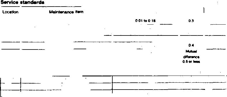
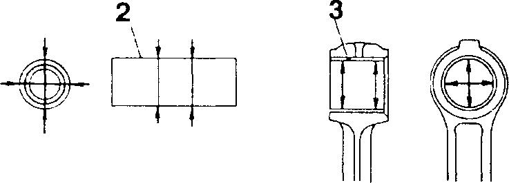
2. Servicestandards table
Only the relevant service standards are shown.

Service standards
Location Maintenance item
1,11 Clearancebetweenstrapboltandstrapplate
7 Pressure spring Installedload (Installed length49.1) Tilt
IThis shows the key No. of the relevant part.
3. Tightening torquetable
This shows specified tightening torque.

0 Tightening torque
Location Parts to betightened
1 Strapbolts (Strapbolt mounting)
4 Bolt (Lockplatemounting)
IThis shows the key No. of the relevant part.
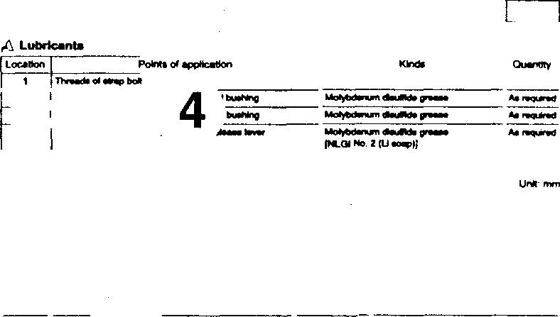
4. Lubricant, fluidand sealanttable
Onlytherelevantlubricant,fluidandsealantare shown.

A'i Lubricant, fluid and sealant
Standard value
0.01to0.16
835N {85kg!}
2.9or less
Tighteningtorque
39 to59 (4to6)
5.9 to7.8 {0.6 to0.8)
Unit: N·m {kgl·m}
RemarksWet I
This shows that the item is to be tightened wet.
This shows the application point.
Location Points ofapplication ,,
1 Threadareaofbolt
10,16 Frictionsurfacesofreleaseleverplateandrelease lever
IThis shows the key No. of the relevant part.
Kinds
LOCTITE272
Molybdenum disulfidegrease [NLGI No. 2(Lisoap)] I
This shows the specified brand.
Quantity
As required
Asrequired
Unit: mm Limit Remedy 0.3 Replace 710 N Replace {72.3kg!} 5.0 Replace
V
HOW TO READ THIS MANUAL
5. Specialtools table
Only the relevant special toolsareshown.
� Special tools Location Tool name and shape
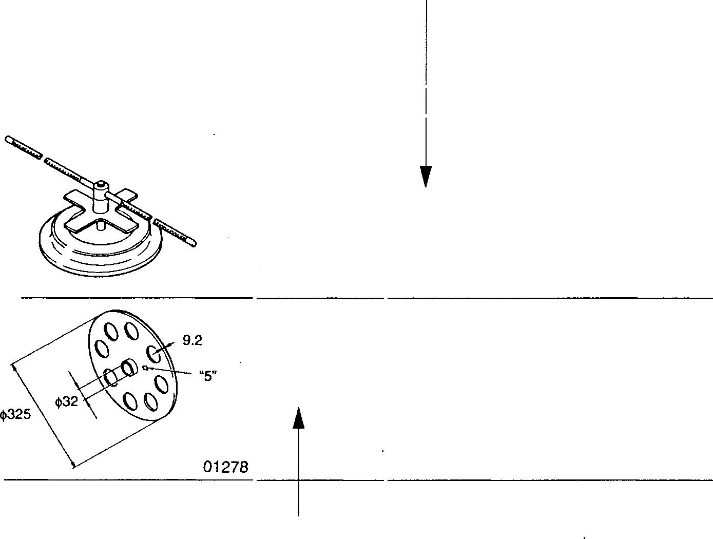
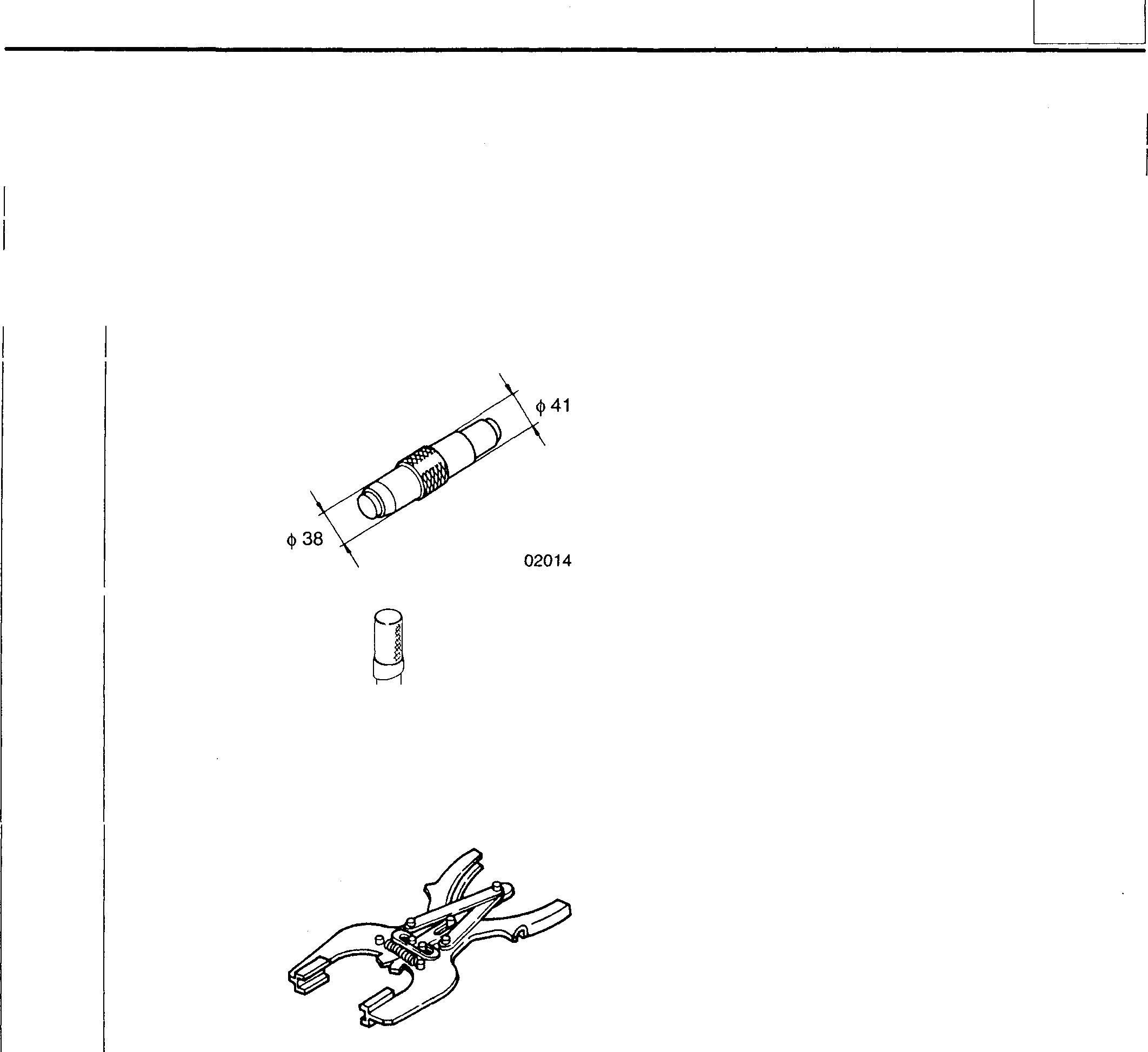
11 Clutchinstaller
01277
Purpose cif specialtoolsisshown.
Part No. Application
16 Masterplate
This shows the key No. of therelevantpart.
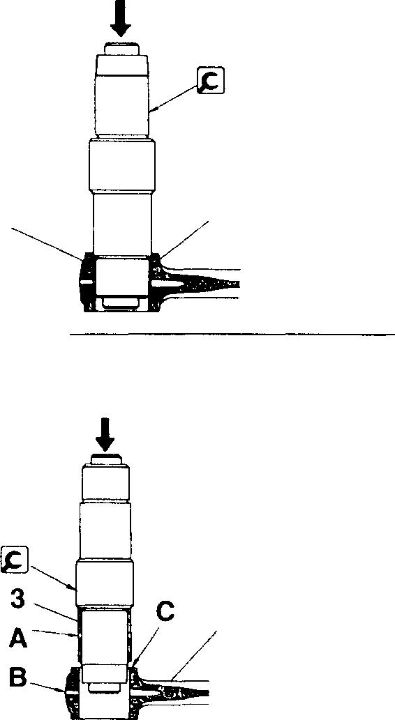
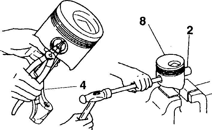
6. Service procedure
Thisindicatesaspecial servicetool.
MH062291 Adjustreleaseleverheights
Unit:mm
MH061051 Removaland installationofclutch cover
Quotethisnumberwhenplacing anorderforthe part.
Thisshowsthe key No. of the relevantpart.
[!!]
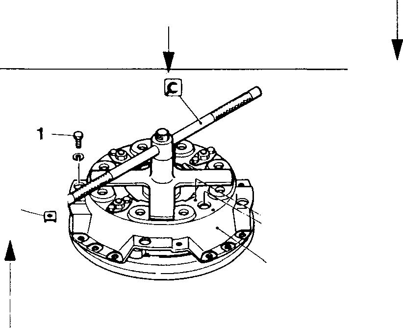
Removal and installation ofclutchcover
• Depress pressure spring 7 using � clutch installer, then removethe followingparts:
Strap bolt 1, washer 2, washer 3, bolt 4, lockplate 5, supportnut 6
• Loosentheclutchinstallergradually,thenremoveclutchcover11when the pressurespringisfully released.
• For installation, followtheremovalsequence in reverse.
IThe key No. referredtointhetextis always the same as the key No. shown in theillustration.
Servicing procedures of disassembly (removal), assembly (installation), inspection, adjustment, etc. areshown collectively.
VI
'f-4 2 I('.. � �6
11 01281
3�
Terms and Units
Theterms and units inthis manualare definedas follows.
• Thisservicemanualcontainsimportantcautionaryinstructionsandsupplementaryinformation underthefollowing four headings which identify the nature oftheinstructionsand information:
DANGER_& WARNING_& CAUTION_& NOTE
• Front and rear
Precautionsthat should be taken inhandling potentially dangerous substances such as battery fluidandcoolant additives.
Precautionary instructions, which, ifnot observed, could result in serious injury or death.
Precautionaryinstructions, which,ifnotobserved, couldresultindamagetoordestruction of equipment or parts.
Suggestionsorsupplementaryinformationformoreefficientuseofequipmentorabetter understanding.
The terms "front" isthe fan side and "rear" the flywheels side of the engine.
• Left and right
The terms "right" and "left" shallbe used toindicatethe side as viewedfrom the flywheel side of the engine.
• Terms of service standards
(1) Standardvalue
Standard value dimensions in designs indicating: the design dimensions of individual parts, the standard clearance betweentwo parts whenassembled, andthe standard valuefor an assembly part, asthe case may be.
The figure in [ ] isthe basicdiameter.
(2) Limit
Whenthe value of a part exceeds this, it is nolonger serviceable in respect of performance and strength and must be replacedorrepaired.
• Tightening torque
Excessive or insufficient tightening torque has particular importance in respect of performance. Accordingly, tightening torqueisspecifiedinlocationsthat are tobetightened.
Wherethere is no specified figure for tightening torque, followthe table covering standard tightening torques.
Whentheitemistobetightened ina wet state, wetisindicated. Wherethereis noindication, read itasdry, and tighten at specified torque.
e Unit
Length, weight, surfaceareaandcapacityareinSIunits. Imperialand metricunitsaregiveninbrackets. Temperaturesare given in degrees Celsius withdegrees Fahrenheit given brackets.
For the conversioninto the foot-pound system, refer to the followingconversion table.
Vil
HOW TO READ THIS MANUAL
Unit
Sign of SI unit
Mass quantity of matter kg lb
Sign of foot-pound unit
Conversion rate
1 kg = 2.2046 lb g oz
1 g= 0.035274 oz
Dimension m ft.
1 m = 3.2808 ft. mm in.
Capacity L gal.
cm3 oz
cm3 cu.in.
1 mm= 0.03937 in.
1 L = 0.2642 gal. (U.S.)
1 L = 0.220 gal. (Imp.)
1 cm3 = 0.033814 oz (U.S.)
1 cm3= 0.035195 oz (Imp.)
1 cm3 = 0.061023 cu.in.
Force N {Newton) lbf
Pressure kPa (kilopascal) lbf/in.2
Stress N/cm2 lbf/in.2
Moment offorce N·m !bf.ft
Output kW (kilowatt) HP
Temperature oc OF

1 N = 0.2248 lbf
1 kPa= 0.145 lbf/in.2
1 kPa= 0.2953 in. Hg
1 N/cm2 = 1.45 lbf/in.2
1 N ·m = 0.7375 !bf.ft
1 kW= 1.34 HP
t°C= (1.8t°C + 32}°F
viii
GROUP 00 GENERAL
GENERAL SPECIFICATIONS . . . . . . . . . . . . . . . . . . . . . . . . . . . . . . . . . . 2 ENGINE NUMBER AND NAME PLATE . . . . . . . . . . . . . . . . . . . . . . . . . . 3 PRECAUTIONS FOR MAINTENANCE OPERATION . . . . . . . . . . . . . . 4 TABLE OF STANDARD TIGHTENING TORQUES . . . . . . . • . . . . . . . . 12 00 I 00-1
Mitsubishi 6D16TLEATadano Crane
MITSUBISHI 6D16TLEA ENGINE SPECIFICATIONS
Item
Engine model I I6D16TLEA
Type
6-cylinder in-line, water-cooled 4-cycle diesel
Combustion chamber type Direct injection type
mechanism Overhead valve (OHV) type
• Empty mass as measured according to Mitsubishi Motors Corporation standard.
Specifications
Bore x Stroke mm 118x115 Total displacement cc 7545 Compression ratio II 17.5 Empty mass kg* I I 580
Valve
00-2
ENGINE NUMBER AND NAME PLATE 00
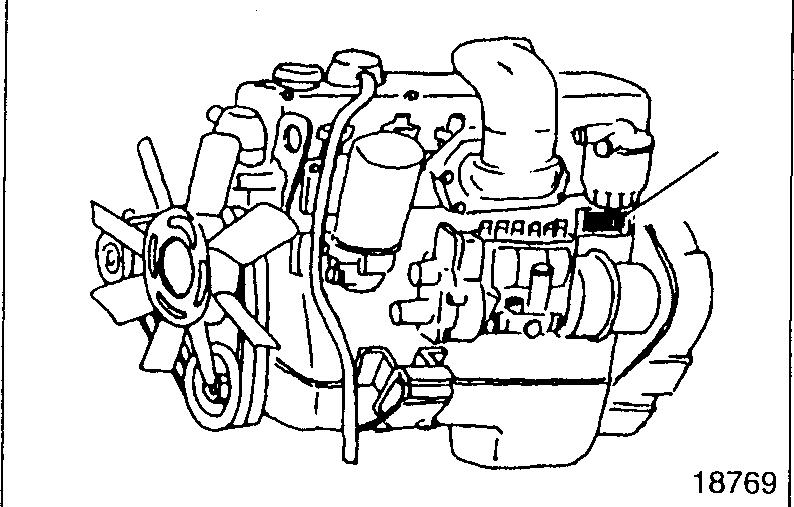
The serialnumber for engine is assignedto the respective engine in manufacturingsequence: every engine has its own number. This number is required for incidental inspection of the engine. Please do not fail to mention this number to the dealers when orderingspareparts.
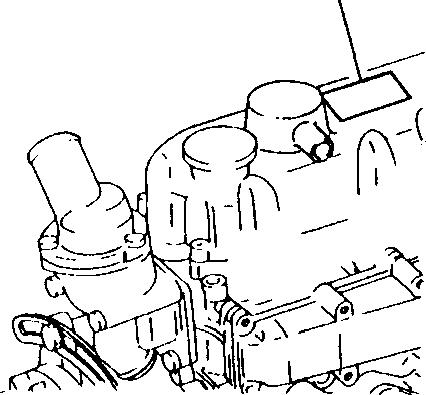
Engine Number
Name Plate
1
Engine number 1 is punch-markedon the left of the crankcase.
Example:6016-DDDDDD
1 CEngine
Engine number model
Nameplate 18779
J... I I I 2 TOTAL CYL VOL 6557cc(4OOcu in)-V OUT PUT [��-JD tc=J rpm - 3
MITSUBISHI MOTORS CORPORATION TOKYO JAPAN VALVE CLEARANCE (COLD) I ���7�/oi��:usT o 41"'����1 6G_���Jj- 4
FUEL INJECTION TIMINGrl0 BTDC j'5
6 18780
Thenameplateisattachedtotheportionshowninthe illustration, andindicate the following items.
1 Engine model
2 Totaldisplacement
3 Maximumoutput
4 Valveclearance
5 Firingorder
6 Fuel injection timing
00-3
PRECAUTIONS FOR MAINTENANCE OPERATION
In order to determine the condition of the vehicle adequately, attend the vehicle beforehand to find and keep record of the accumulated mileage, operating condition, what the customer's demand is, and other information that may be necessary. Prepare the steps to be taken and perform efficient and wasteless maintenance procedure.
X0Determine where the fault exists and check for the cause to see whether removal or disassembly of the part is necessary. Then follow the procedure specified by this manual.
Perform maintenance work at a level area. Prepare the following.
• Prepare general and special tools necessary for the maintenance work.
WARNING&-------------
Do not attempt to use tools other than special tools where use of special tools is specified in this manual. This will avoid injury or damage.
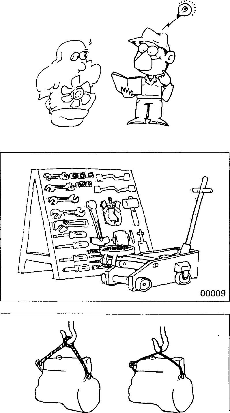
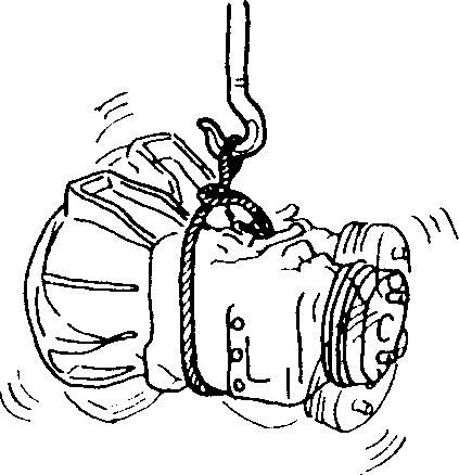
Pay special attention to safety when removing or installing hea1/y items such as engines, transmissions.
When lifting up heavy items using cables, pay special attention to thefollowing points:
• Checkthemassoftheitemtobeliftedanduseacablecapableoflifting that mass.
• If you do not have the specified lifting hanger, secure the item using cable taking the point-of-balance of the item into consideration.
• You must work in a position where you will not be injured ev,en if the cable comes undone and the lifted item falls.
18770
14194 14195 00-4
Be particularly careful not to work in shoes that have oily soles and are slippery. When working as a team of two or more, arrange signals in advance and keep confirming safety. Be careful not to accidentally bump switches or levers.
Check for oil leakage before cleaning the area having the fault otherwise you might miss detecting the leakage. Prepare replacement part(s) beforehand.
Replace oil seals, packing, 0-rings and other rubber parts; gaskets and split pins with new parts whenever any of them has been removed. Use only genuine MITSUBISHI replacement parts.
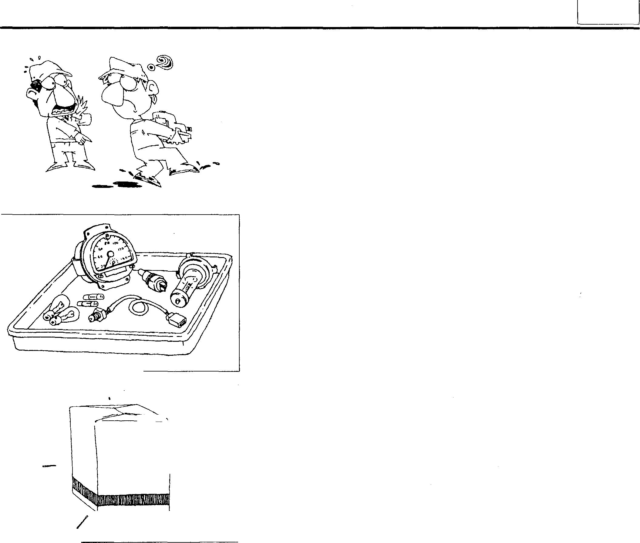
On disassembly, visually inspect all partsfor wear andtear, cracks, damage, deformation, degradation, rust, corrosion, smoothness in rotation, fatigue, clogging and any other possible defect.

00012 00014 ' / / ......... � � ......... ;.. / 1m�ij���m� --CfOlJIB® --/ '
[)C)��0 _di I 0 � " \ . ,r /
00
00015
00016
00-5
PRECAUTIONS FOR MAINTENANCE OPERATION
Put alignment marks on part combinations before disassembly and arrangethedisassembledpartsneatly.Thiswillhelpavoidmismatingofthe parts later.
Putthealignmentmarks, punchmarks, etc. where performance andappearancewill not be affected.
Cover the area left open after removal of parts tokeep it free from dust.
CAUTION.&_--------------
• Take care to avoid mixing up numerous parts, similar parts, left and right, etc.
• Keepnewpartsforreplacement andoriginal(removed)partsseparate.
Applythespecified oil orgreaseto U-packings, oilseals, dust seals and bearingsduringassembly.
Use only the specified oil, grease, etc. for lubricant, remove the excess immediately after application with a piece ofwaste, etc.
CAUTION.&_--------------
When the specified lubricant, fluid and sealant is not available, you may use an equivalent.
00018
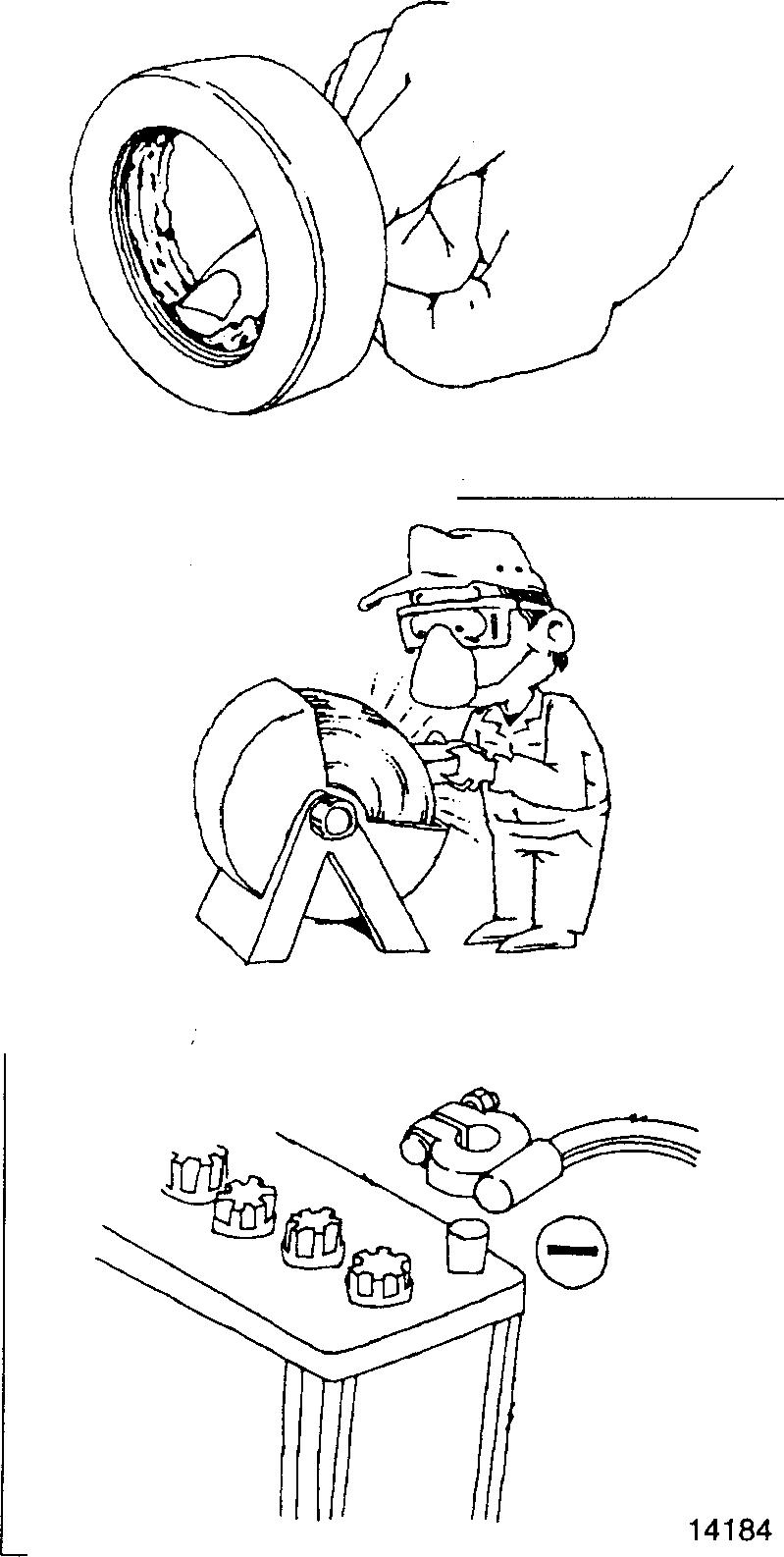
Weargoggleswhenusingagrinderorwelder. Payfullattentiontosafety bywearinggloveswhen necessary. Watchoutforsharpedges, etc. that mightinjure yourhands or fingers.
00019
Beforecarryingoutmaintenanceworkontheelectricsystem,disconnect thenegativeterminalsofthebatteriestopreventthemfromshort-circuiting andburning-out.
CAUTION.&_-
Be sure to turn starter and lighting switches, etc. off before disconnecting or connecting battery terminals, because the semiconductors can be damaged.
00-6
Take care when handlingsensors, relays, etc. which are vulnerable to shockandheat. Donotattemptto removethecoverfrom, orapplypaint to, the electroniccontrol unit.
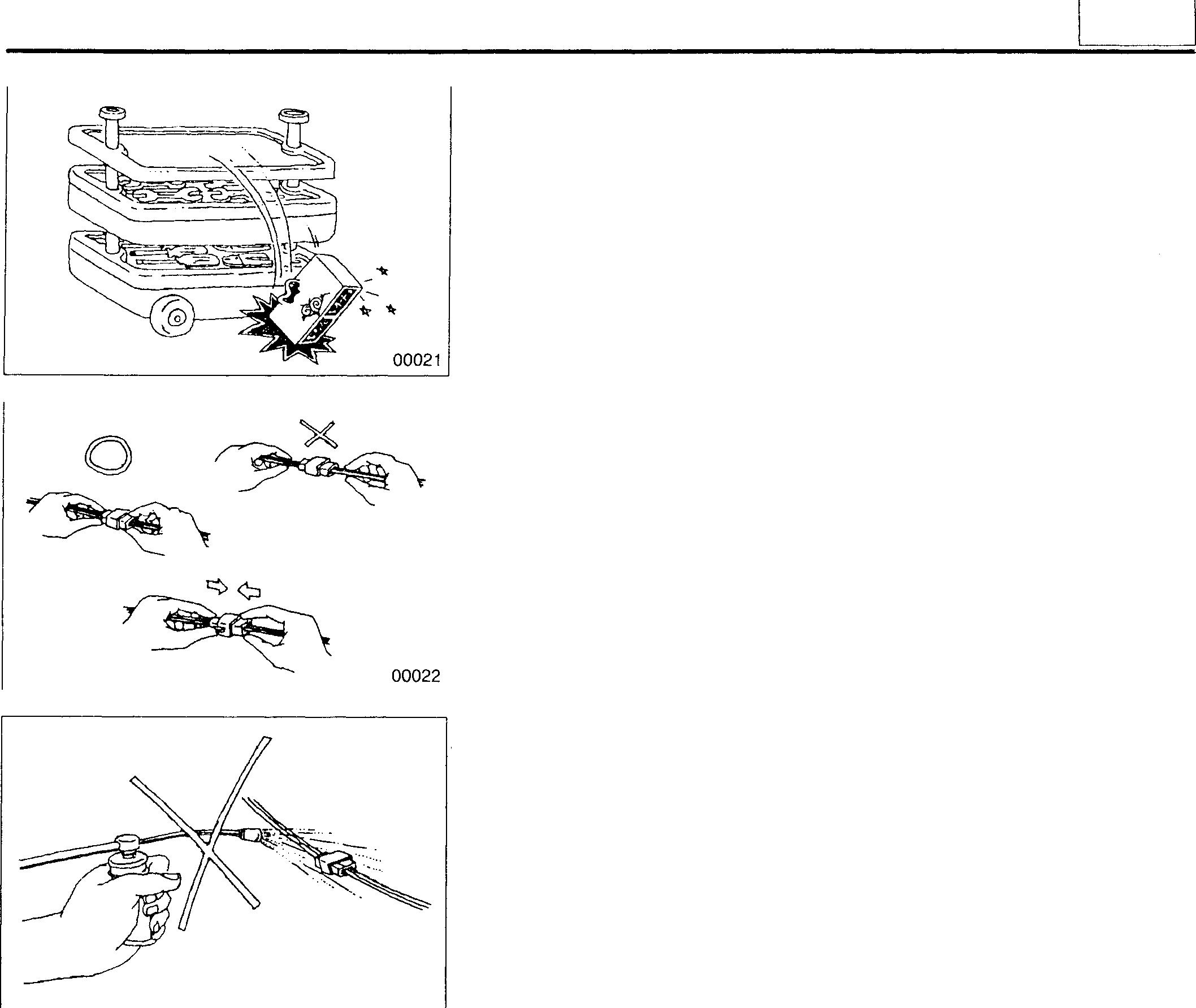
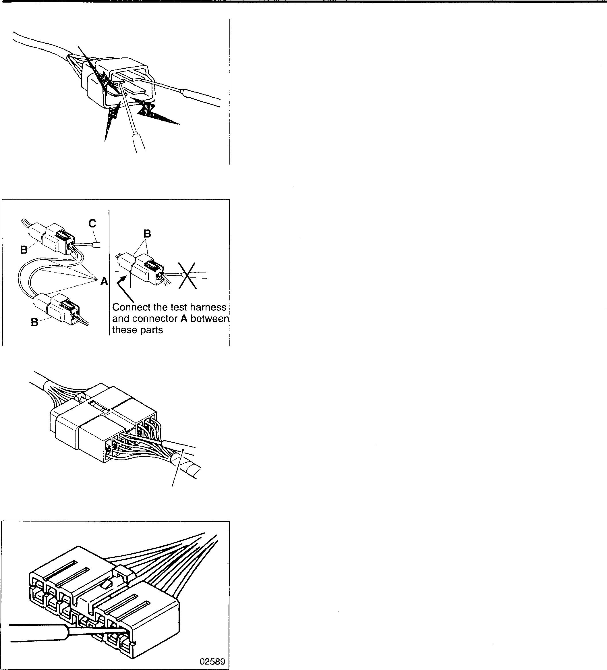
Pulltheconnector, andnotthe harnesslead, toseparateconnectors. To separate a lock-typeconnector, first pushtowardarrow mark. To reconnect a lock-type connector, pressthe separated parts until they click together.
When washing the vehicle, cover the electric system parts and instrumentswithwaterproofmaterialbeforehand (Coverwithvinylsheet orthe like). Keepwaterawayfromharnesswireconnectorsandsensors. Ifany of them should getwet, wipe them off immediately.
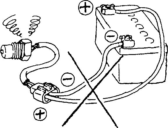
Whenusinganelectricwelder, suchelectronicpartsthataredirectly connectedtothebatteriesmightbedamageddue totheflowofcurrent from thewelderthatflowsthroughthenegativecircuit. Partsthathaveswitches might be subject to the samedangerif the switches are left on. Therefore, do not fail toobservethefollowing.
• Connectthenegativeterminalofthewelderasnearaspossibletothe area that isto be welded.
• Disconnectthe negative terminals ofbatteries.
To apply voltage fortesting, check thatthe positive and negative cables are connected properly, then increase voltage gradually from O volt. Do notapplyvoltagehigherthanthespecifiedvalue.
Inparticular,paycloseattentiontotheelectroniccontrolunitandsensors, since they are not always fedthe battery voltage.
00023 14185 00
00-7
PRECAUTIONS FOR MAINTENANCE OPERATION
00027
Measurement Procedures Using Connectors
02587
02588
When using testers or the like for continuity tests, be careful not to allow test probes to touch the wrong terminals.
Testwithconnectorsengaged(continuitythroughcircuitobtained)
<Waterproof connector>
PrepareatestharnessandconnectorsA, thenconnectifbetweenthetwo parts of harness B that is to be tested. Check the circuit by touching test probe C to the test connector.
Never insert the test probe from the harness side of the waterproof connection, or waterproof performance might be diminished causing corrosion of the connector.
<Non-waterproof connector>
Insert test probe C from the harness sideof the connector. Wherecontrol units, etc. haveconnectors that are too small to accept the testprobe, do not force the test probe into them.
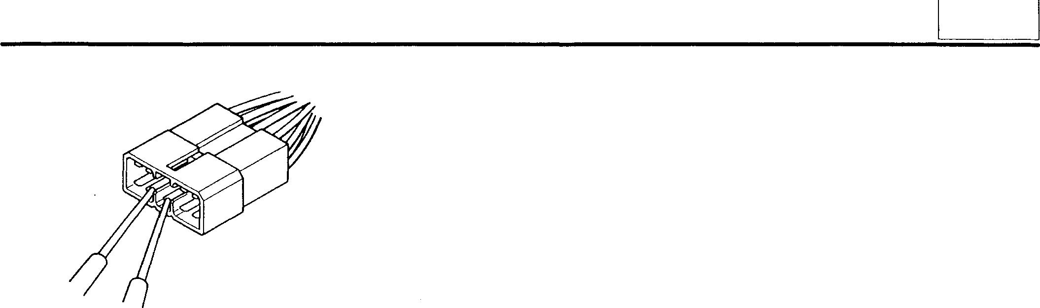
Test with connectors disengaged
Using female pins
Insert a test probe into a terminal. However, do not force the probe into the terminal, or it will cause a poor contact.
C
00-8
Usingmale pins
Touchthe pinsdirectly usingtest probes.
CAUTION_&--------------
Be surethatyoudo not shortcircuit theconnectorpins whenyou use the test probe because this could damage the internal circuit of the electronic control unit.
02590
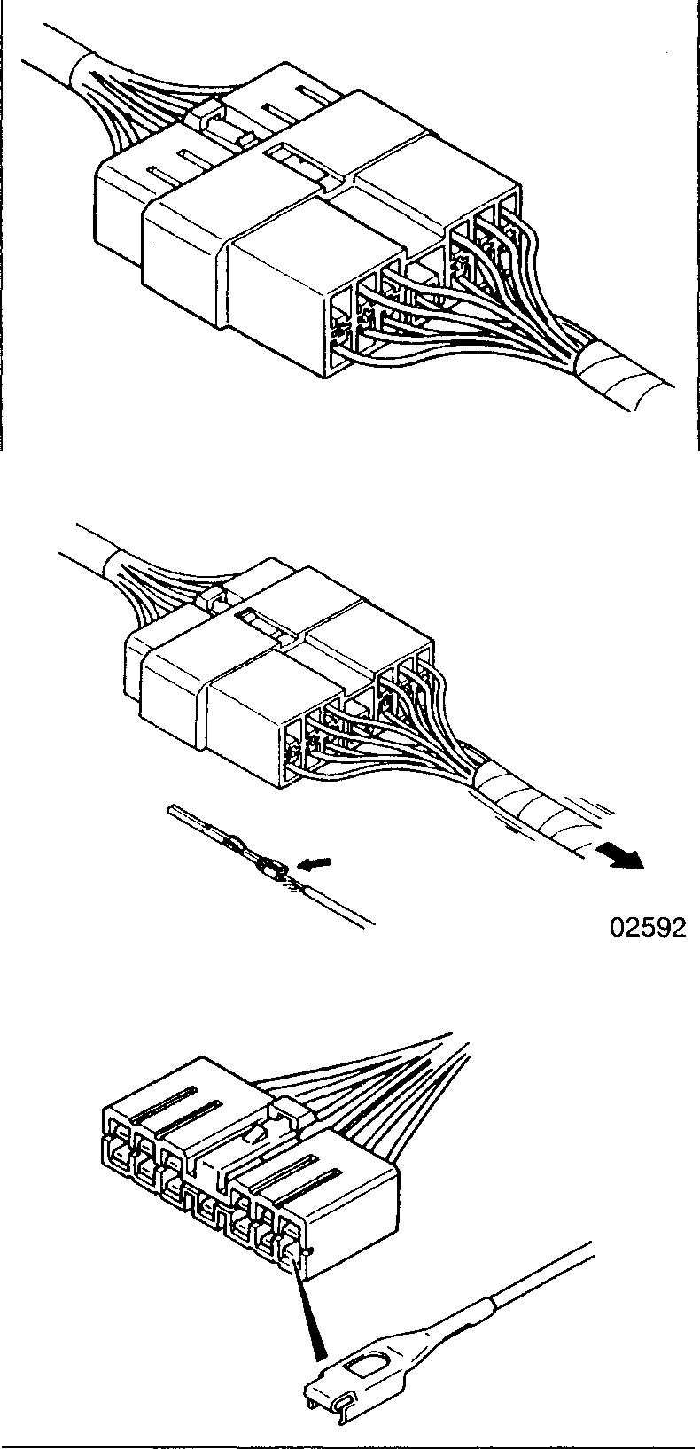
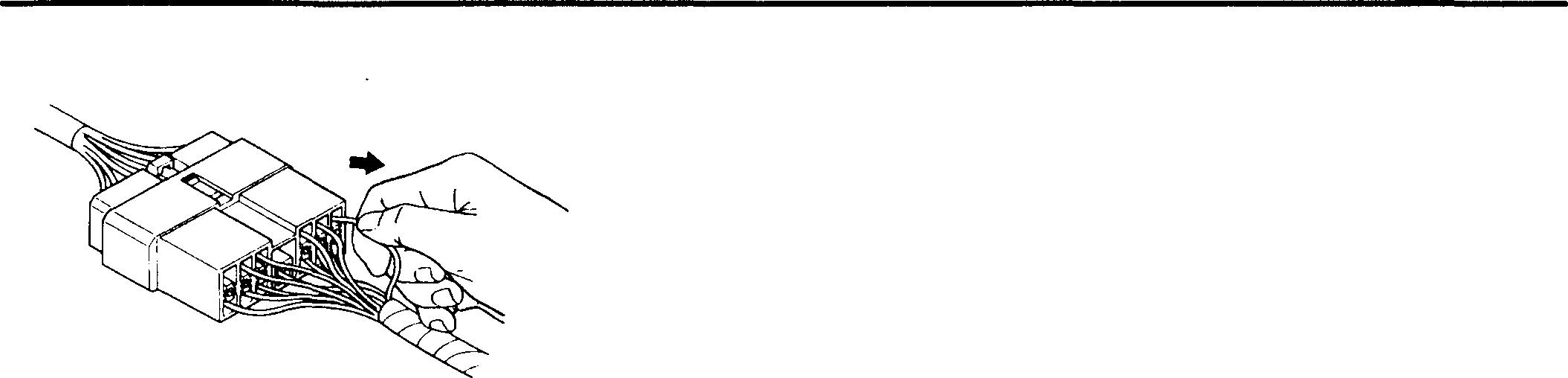
Connector Inspection Procedures
02591
Visual inspection
Checkfor looseconnectionand poor engagement.
02593
Check if harnesses are broken by pullinggently around the terminals.
Checkfor adecreaseincontact pressure betweenthe male and female terminals.
Checkforpoorcontactcausedbyconnectorpinshavingfallenout, rusted terminals or foreign particles.
00
00-9
PRECAUTIONS FOR MAINTENANCE OPERATION
Connector pin fall out inspection
02594
Damagedconnectorpinstopperscancausepoorengagementoftheterminals(maleandfemalepins)eveniftheconnectorbodyissecured,and mightcause somepins tofall out. Check if the pinshave fallenout from the connector by pullingeachharness gently.
Inspection Procedures for Blown Fuses
A02596
Remove fuse B andmeasure resistance betweenthe loaded sideofthe fuse andground.
Turnonallcircuitswitches(connectedtothefuse). Iftheresistancevalue readingisapproximately 0, ashorthasoccurredbetweentheswitchand theloadedpoint.Avalueofotherthanzeromay indicatethatthefusewas blown by a temporary short but the short is no longer present.
The majorcauses of ashort circuit are as follows:
• Harnessstuckonto thevehicle body.
• Harness sheath damaged by friction or heat.
• Water inconnectors or circuits.
• Mistakes (accidental short circuits)
A: Battery
8: Fuse
C: Loaded switch
D: Load
E: Short circuit
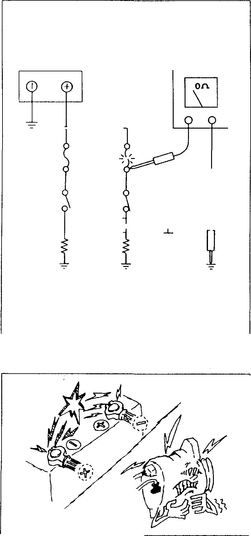
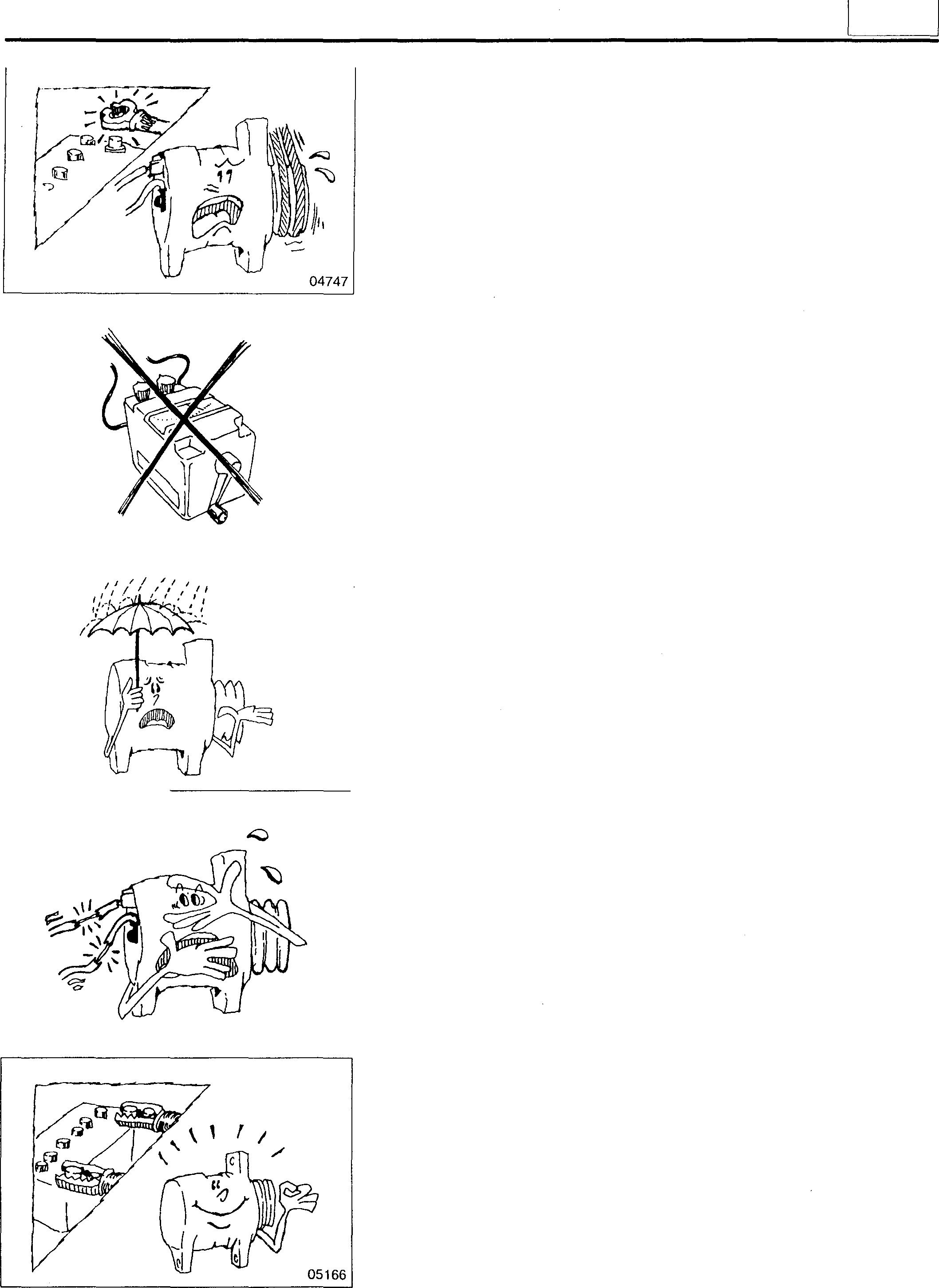
Precautions for Handling Alternator
When servicing the alternator, pay attentiontothe following:
• Do not connectthe alternator with battery polarities reversed. If the alternator is connected with reversed polarities, a large current flowfromthebatterytothealternatoroccurs,andthediodeorregulator might be damaged.
04746
B C E r ---, I----, I L --7 -=- : D L J
/
00-10
• Whilethe engineis running, do notremovethe battery terminals. If the battery terminals are removed at that time, a surge voltage is generated and the diode or regulator might be weakened.
• Do not use a high-voltage tester such as a megger for inspection. If a high-voltage tester is used, the diode or regulatormight be destroyed.
• Do not splash water over the alternator.
If wateris directly splashed over the alternator, individual components will be short-circuited and might be destroyed.
• Donotshort-circuitterminal Bandterminal Lwhilerunningthealternator.
If the terminals are short-circuited while the alternator is running, the diode trio might be destroyed.
• Disconnect the battery terminals before quick-charging the battery. Quick-charging without disconnecting the battery terminals might damage the diode or regulator.
00
02371 05165 04749
00-11
TABLE OF STANDARDTIGHTENING TORQUES
• Use specifiedboltsandnutsandtightenthem atspecifiedtorquesaccordingtothe followingtable, unless otherwise specified.
• Threads and contact seats shall be dry.
• Where there is a difference in strength classification between the nut and bolt (or stud bolt), the torque specified for the bolt shall apply.
Hex-head Bolt and Stud Bolt
Unit: N ·m {kgf·m} Strength 4T 7T ST classification !�©0 0 ©0 0 ® @ 0 r n I (Stud) (Stud) (Stud) 02154 MS 2to3 4to6 5to7{0.5to0.7}{0.2to0.3} {0.4to0.6} M6 4to6 7to11 8to12 {0.4to0.6}{0.7to1.1}{0.8to1.2}MS 9to14 17to26 20to29 - -(0.9to1.4} (1.7to2.6} (2.0to3.0} M10 19to28 18to26 36to52 33to49 45to60 41to59 (1.9to2.8} {1.8to2.7} (3.5to5.5} (3.5to5.0} (4.5to6.0} (4.3to6.9} M12 35to50 31to46 70to95 65to85 85to110 75to100 (3.4to5.0} (3.1to4.7} (7.0to9.5} (6.5to8.5} {8.5to11} (7.5to10} M14 60to85 55to75 120to160 11oto140 130to180 120to160 (6.0to8.5} (5.5to7.5} {12to16} (11to14} (13to18} {12to17} M16 90to130 90to120 180to240 160to220 200to270 190to260 {9.5to13} (9.0to12} (18to24} (16to22} (20to27} (19to26} M1S 140to190 120to160 260to340 220to290 290to390 260to340 {14to19} (12to16} (25to35} (22to30} (30to40} { 26to35} M20 190to260 170to230 350to470 320to420 410to550 370to490 {19to26} {17to23} (36to48} {32to43} (41to56} (37 to50} M22 260to340 230to300 470to640 430to570 550to740 490to 670 {26to35} {23to31} {48to65} (43to58} (56to75} {50to68} M24 340to450 290to390 630to840 540to730 730to980 630to 840 (34to46} {29to40} {63to86} (55to74} (74to100} (64to 86}
Unit: N · m {kgf·m} Strength 4T 7T ST classification � (0) � 0 0 � 0 r n y 02154 M6 4to6 8to12 9to14 (0.4to0.6}{0.8to1.2}(0.9to1.4}MS 10to15 19to28 22to32 -{2.2to3.3} (1.0to1.5} (1.9to2.8} M10 21to30 20to28 39to58 37to53 50to65 45 to 65 (2.1to3.1} {1.9to2.9} (3.9to6.0} (3.6to5.4} (5.0to6.5} (4.5 to 6.5} M12 38to54 35to51 80to110 70to95 90to120 85to110 (3.8to5.5} (3.4to5.2} {8.0to11} (7.0to9.5} (9.0to12} (8.5to11} 00-12
Hex-head Flange Bolt
Hex-head Nut

Hex-head


00
Unit: N · m { kgf· m} Strength 4T class ification
r I Sta ndardscrew Coarsescrew MS 2to3 {0.2to0.3) M6 4to6(0.4to0.6) M8 9to14 0.9to1.4) M10 19to28 18to26 (1.9to2.8) (1.8to2.7) M12 35to50 31to46 {3.4to5.0) {3.1to4.7) M14 60to85 55to75 (6.0to8.5) {5.5to7.5) M16 90to130 90to120 (9.5to13) (9.0to12) M18 140to190 120to160 {14to19} (12to16) M20 190to260 170to230 (19to26) {17to23) M22 260to340 230to300 {26to35) {23to31} M24 340to450 290to390 {34to46) {29to40)
� @
Strength 4T class ification Repre-
sentation Diameter 02155 symbol Sta ndardscrew Coarsescrew M6 4to6 {0.4to0.6)M8 10to15 (1.0to1.5)M10 21to30 20to28 (2.1to3.1) {1.9to2.9) M12 38to54 35to51 (3.8to5.5) {3.4to5.2) 6T © @ (DJ CED 02155 Sta ndardscrew Coarsescrew 4to6 (0.4to0.6) 7to11{0.7to1.1} 17to26 (1.7to2.6) 36to52 33to49 {3.5to5.5) (3.5to5.0) 70to95 65to85 (7.0to9.5) (6.5to8.5) 120to160 110to140 {12to16} (11to14) 180to240 160to220 (18to24) (16to22) 260to340 220to290 (25to35) {22to30) 350to470 320to420 {36to48) {32to43) 470to640 430to570 (48to65) {43to58) 630to840 540to730 (63to86) {55to74) 00-13
Flange Nut Unit: N ·m {kgf·m}
(@)
TABLE OF STANDARDTIGHTENING TORQUES
Tightening torque forflarenutfor generalpurpose Unit: N ·m {kgf· m}
Pipediameter <j>4.76mm <j>6.35mm <j>8mm <j>10mm <j>12mm cp15mm
Tightening torque 17{1.7} 25{2.6} 39{4.0} 59(6.0}
Tighteningtorquefor airpipingnylontubeforgeneral purpose {DIN type}
Standarddiameter 6x1mm 10x1.25mm 12x1.5mm
Tighteningtorque 20+5.9 { 2.0�g-6}
{ 3.0��-0} 49+9.8 { 5.0��-0} -0 -0 -0
88(9.0} 98{10.0} Unit: N · m {kgf· m}
1.5mm
{ 5.5��-0l -0
Tighteningtorquefor air pipingnylontubeforgeneralpurpose {SAE type}
Standarddiameter 1/4in. 3/8in. 1/2 in.
Tightening torque
N · m {kgf· m}
in.
{ 1.3�g.4}
{ 3.o �g-5}
{ 5.o �g-5} -0 -0 -0
{ 6.5�g-5} -0
29+9.8
13+3.9
29+4.9
00-14
54+4.9
Unit:
5/8
64+4.9
49+4.9
15x
SPECIFICATIONS ............................................ 2 STRUCTURE AND OPERATION ............................... 3 TROUBLESHOOTING......................................... 7 ON-VEHICLEINSPECTION AND ADJUSTMENT 11 • Measuring Compression Pressure ..................• • ••• • • • • •• •• •• • • 8 I • Inspecting and Adjusting Valve Clearances ........................... 1O CYLINDER HEAD AND VALVE MECHANISM .................... 12 PISTONS, CONNECTINGRODS, AND CYLINDER LINERS ....... 28 FLYWHEEL PTO ............................................. 44 FLYWHEEL .................................................. 48 TIMING GEARS .............................................. 54 CAMSHAFT.................................................. 64 CRANKSHAFT AND CRANKCASE ............................. 72 11-1
GROUP 11 ENGINE
Mitsubishi 6D16TLEATadano Crane
MITSUBISHI 6D16-TLEAENGINESPECIFICATIONS
Item
Specifications
Engine model I6D16TLEA
Type
6-cylinder, in-line, water-cooled, 4-cycle diesel
Combustion chamber type Direct injection
Valve mechanism Overhead valve
Cylinder borexstroke mm
Mitsubishi 6D16TLEA engine parts contact:
email: engineparts2@gmail.com
Phone: 269 673 1638
Text: 269 760 8652
<j>118x115 Total displacement cc I 6919 7545 Compression ratio I I 17.5 11-2
Mitsubishi 6D16TLEATadano Crane
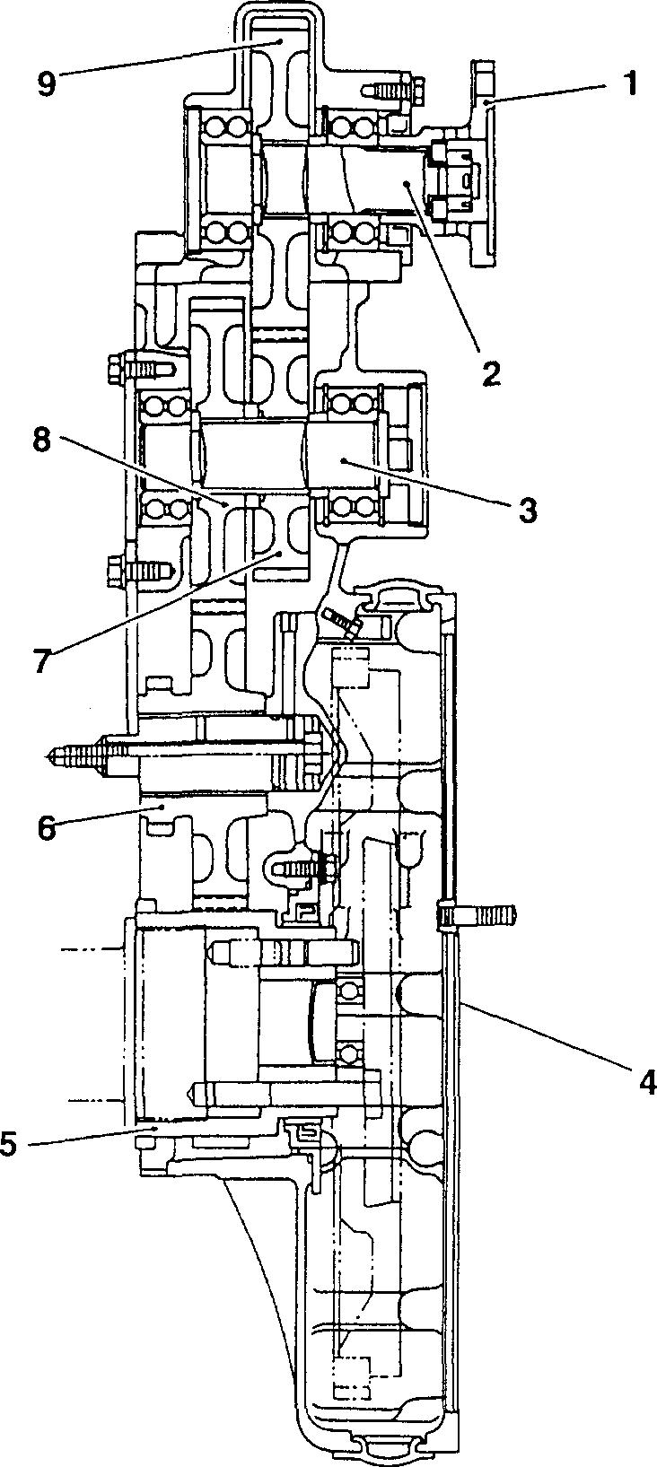
STRUCTURE AND OPERATION
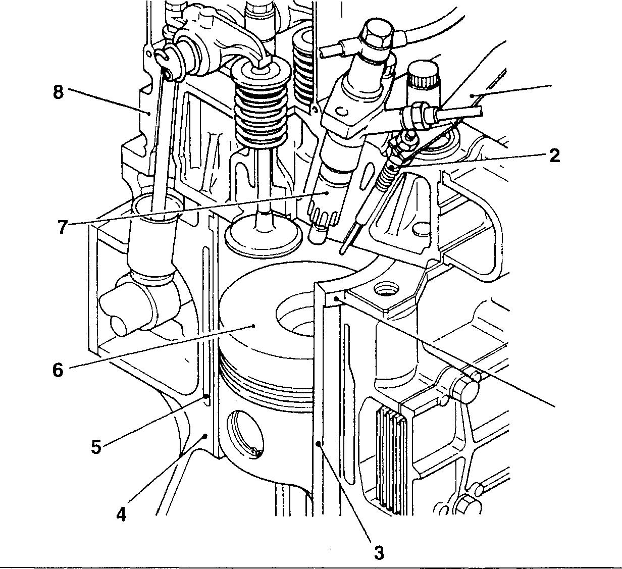
1 Connecting plate
2 Glow plug
3 Cylinder liner
4 Crankcase
5 Waterjacket
6 Piston
7 Injectionnozzle
8 Cylinderhead
11
11-3
Mitsubishi 6D16TLEA Tadano Crane
STRUCTURE AND OPERATION
Valve Mechanism
10
2 16
1 Exhaust valve
2 Inlet valve
3 Camshaft
4 Tappet
Push rod
Rocker shaft
Rocker shaft spring
Rocker
Rocker shaft bracket
Valve cap
Valve cotter
Upper retainer
Outervalve spring
Inner valve spring
Valve stem seal
Valve guide
• The valve stem seals 15 are fitted onto the valves1,2to control the amount oflubricant flowing onto the sliding surfaces of the 01926 valves 1, 2 and valve guides 16.
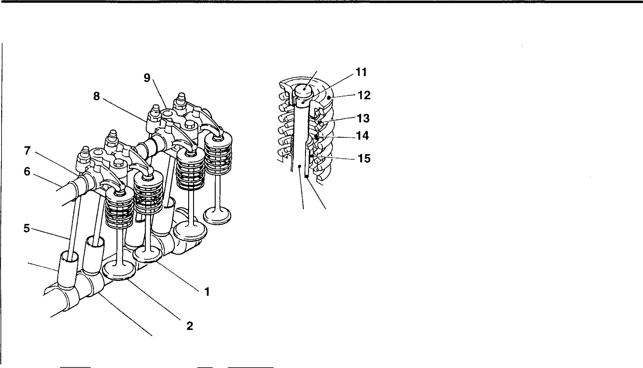
• The valve springs 13, 14 are unevenly pitched to prevent abnormal vibration at high speeds. To prevent the inner and outer springs from meshing with each other, the springs are wound in opposite directions.
• Tofacilitate removalandreinstallationofthe camshaft from the rear end of the crankcase, thediameterofeach bushingissmaller toward the front of the engine.
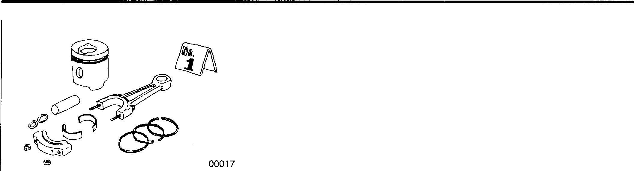
Connecting Rods
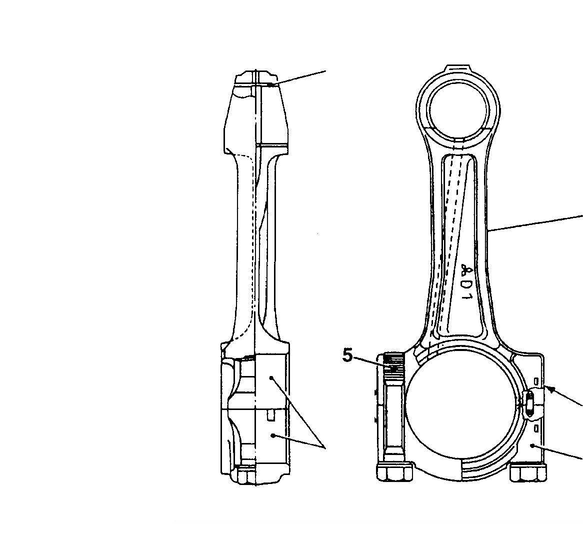
1 Connecting rod bushing
2 Connectingrod
3 Connecting rod bearing
4 Connecting rod cap
5 Connectingrod bolt
A: Alignment mark
4 3 /
1,
7
8
9
10
11
12
13
14
15
16
5
6
'------
11-4 1 3 2 A 4 13622
Mitsubishi 6D16TLEA Tadano Crane
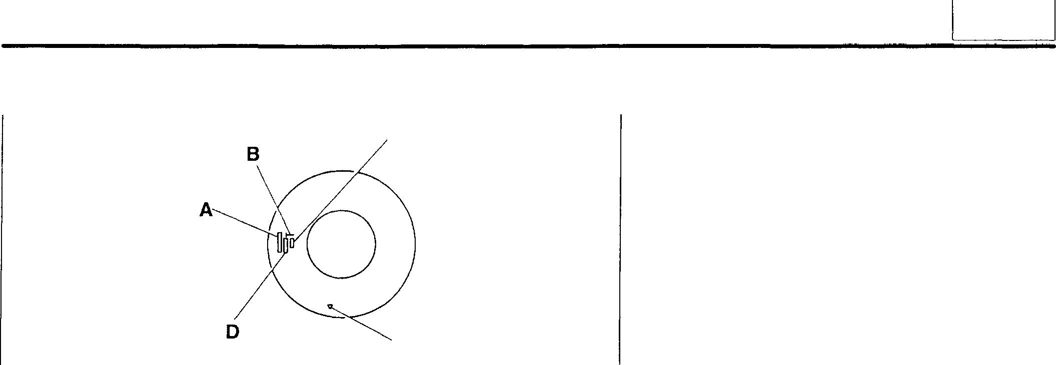
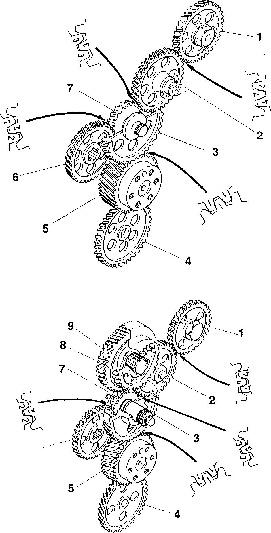
Timing Gears
<Without flywheel PTO> 16937
<With flywheel PTO>
A: Stamped number
B:"T"mark
C: Size mark
D: Weight mark
b.: Front mark
1 Camshaft gear
2 No. 2 idler gear
3 No. 1 idler gear
4 Oil pump gear
5 Crankshaft gear
6 Air compressor drive gear or injection pump drive gear
7 No. 1 idler gear
8 PTO idler gear
<models with flywheel PTO>
9 PTO idler gear
<models with flywheel PTO>
Each gear is stamped with a timing gear alignmentmark ("1", "2", "3", or"4") tofacilitatereassembly.
Pistons C "/::;."
5--·
11
16938
11-5
Mitsubishi 6D16TLEA Tadano Crane
STRUCTURE AND OPERATION
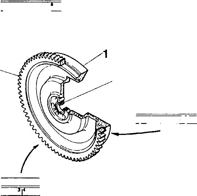
Flywheel
Flywheel PTO
1 Flywheel 2 Pilot bearing
3 Ring gear
A: Angle scale, cylinder number
1 Flange
2 PTO shaft
3 PTO idler shaft
4 Flywheel housing
5 Crankshaft gear
6 No. 1 idler gear
7 PTO idler gear
8 PTO idler gear
9 PTO gear
Theflywheel PTOisfittedontothetopoftheflywheel housing4andisdriven bythecrankshaft gear 5.
I IHIU!111U111IHIII 'I \ 32 A I h1ntw11mrhwl 111 01934
01935 11-6
Mitsubishi 6D16TLEA Tadano Crane
TROUBLESHOOTING
Possiblecauses
Incorrect oil viscosity
lncorrecl/defective fuel
Incorrect valve clearance
Defective cylinder head gasket
Worn valve/valve seat, and carbon deposits
Weakenedvalve spring
Worn/damagedpiston ring(s)
Worn/damagedpiston ringgroove(s)
Incorrectinjectiontiming
Defective injection pump
Defectivecoolingsystem
Defectiveinjectionnozzle(s)
Air trappedin fuelsystem
Cloggedaircleaner
Clogged muffler
Defective turbocharger
Incorrectlyfitted pipe(s)/hose(s)
Symptoms
Injection pump, alternator, orotherauxiliarydevice(s)defective/incorrectlyfitted
Loose/damaged V-belt
Incorrectly fitted crankshaft pulley
Defective air cleaner or muffler
Defective valve spring(s)
Defectiverockershaftand bracket
Incorrect lubricationof rocker shaft bracket
backlash in timing gears
lubricationoftiming gear peripheries and idler shafts
Worn connecting rod small end bushing and piston pin
Worn/damagedcrankshaft pin andconnectingrod bigend bearing
Worn/damaged crankshaftjournal and main bearing
Excessive end play in crankshaft and camshaft
Worn tappet(s) and camshaft

Incorrect
Incorrect
(I) o C :5 C :5 "6> 0 (I) cij ::: 0 E C. 0 ::: C 0 ....J <l'. 0 0 0 0 0 0 0 0 0 0 0 0 0 0 0 0 0 0 0 0 0 0 0 0 0 0 0 0 0 0 0 0 0 0 0 0 0 0 0 0 0 Gr 12 ,JlGr13 [CGr13 [CGr13 ,Gr14 IDGr13 CJ:Gr13 Gr15 !J�Gr15 lTGr15 :J:Gr13 Remarks Gr13, 54 !l'Gr14 J:Gr15 11 ll-7
ON-VEHICLE INSPECTION AND ADJUSTMENT
Measuring Compression Pressure
Service standards
Location Maintenanceitem
- Compression I Each cylinder(at200rpm) pressure I Cylinder-to-cylinderpressuredifference
� Specialtools
Location
Compression
Tool nameand shape
Standard value Limit
2550kPa {26 kgf/cm2} 1960kPa {20 kgf/cm2} - 390kPa {4 kgf/cm2}
Part No. Application
Remedy Inspect Inspect
Unit: mm
16Wx1�
<!>9
MH061461
Measuringcompressionpressure GaugeAdapter
Centredistance46 01942
Reductions in compressionpressureshouldbe used asaguidein determiningthetimingof engineoverhauls. Takemeasurements regularlyand keep track ofchanges; an overview of pressure variations can beuseful in faultdiagnosis. During the engine's run-in period and after parts have been replaced, the compression pressure will increase slightly as piston rings, valve seats, and other parts fitsnugly in position. The pressure will then normalizeas parts wear.
• Before inspections, checkthat theengineoil, starter, and batteryare normal.
• Warm up theengineuntilthecoolanttemperature reaches75 to 85°C.
• Turn off all lights and auxiliary devices.
01938
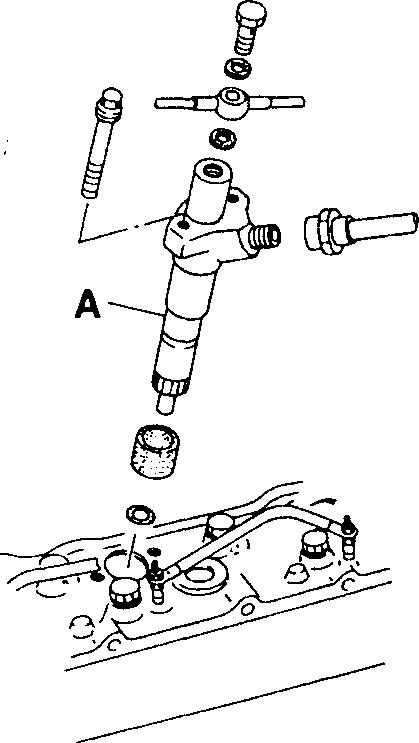
• Removetheinjection nozzleA. [DGr13 CAUTIONL'.t,-------------
Coverthe mounting holesandinjectionpipestopreventtheentry of dust and dirt.
ll-8
01939
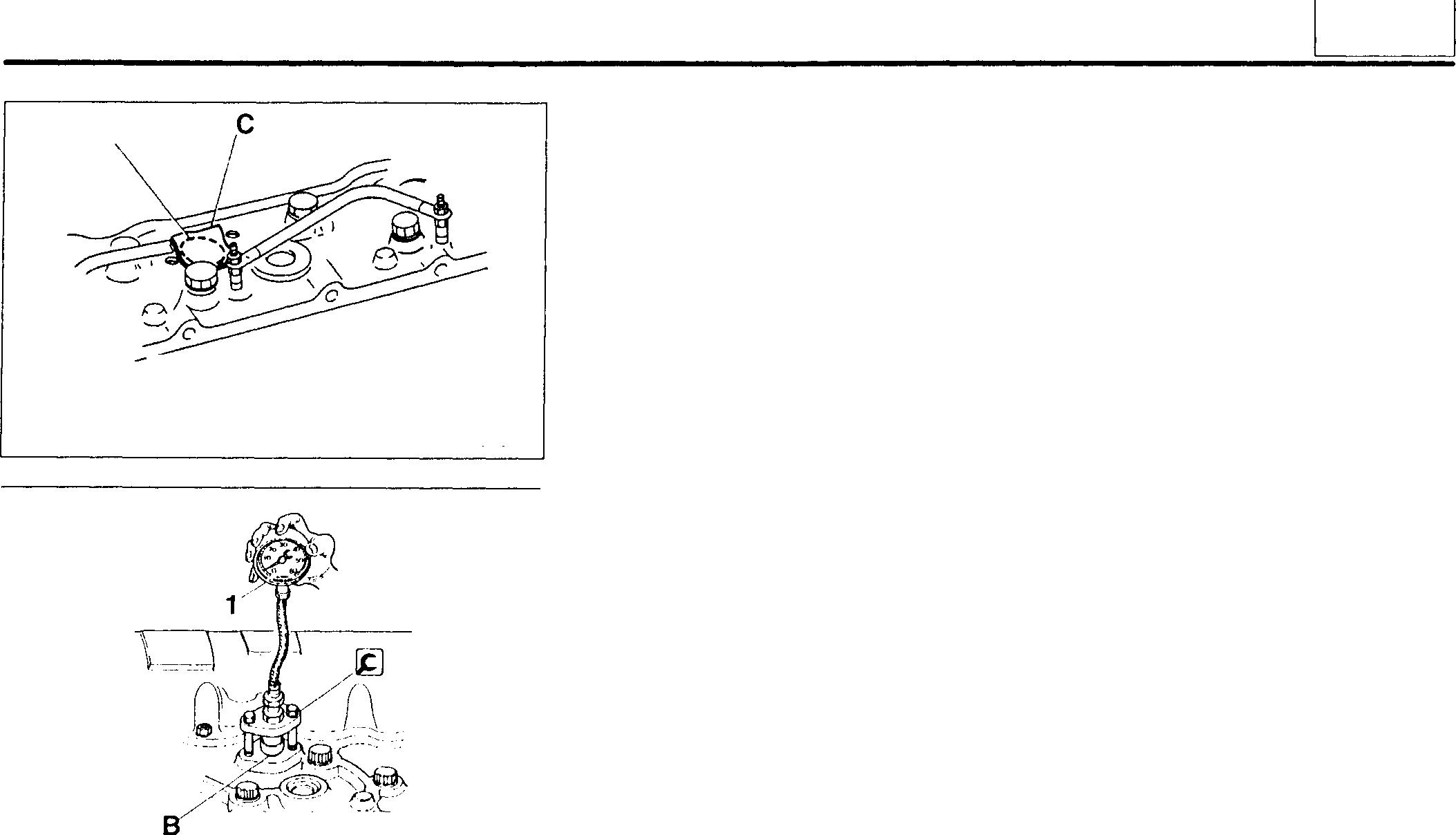
• Cover the injection nozzle mounting hole B with a cloth C. Then, turn the engine over with the starter and check that no foreign matter adheres to the cloth.
WARNING_&-------------
If any cylinder is cracked, coolant, engine oil, and fuel will enter the cylinder through the crack. When the engine is turned over, these substances will spray out of the nozzle mounting hole B at ahightemperature. Forsafety, moveawayfromthenozzlemounting hole before turning over the engine.
• Fitthe�CompressionGaugeAdapterontoaninjectionnozzlemounting hole B together witha nozzle gasket. Then, connect the compression gauge 1.
• Turn the engine over and measure the compression pressure.
• Measure the compression pressure in every cylinder and determine the pressure differences between cylinders.
• If any compression pressure or cylinder-to-cylinder pressure differenceexceedsthespecifiedlimit, pouralittleengineoilinto thecylinder via the injection nozzle mounting hole B then take the measurement again.
• If the compressionpressure increases, there may be wear or damage on piston rings and inner surfaces of cylinders.
• If the compression pressure does not increase, valves may be seizedorincorrectlyseated, orthecylinder headgasketmay bedefective.
B �11735
11
11-9
Mitsubishi 6D16TLEA Tadano Crane
ON-VEHICLE INSPECTION AND ADJUSTMENT
Inspecting and Adjusting ValveClearances
Service standards Unit: mm
Location Maintenance item Standard value Limit Remedy - Valve clearance (whencold) 0.4 - Adjust
0 Tightening torques Unit: N·m {kgf·m}
Location Parts to be tightened
torque Remarks 2,6 Rockerarm adjusting screw locknut 34 (3.5} -
Valve clearances should be checked and adjusted when the engine is cold.
<Without flywheel PTO>
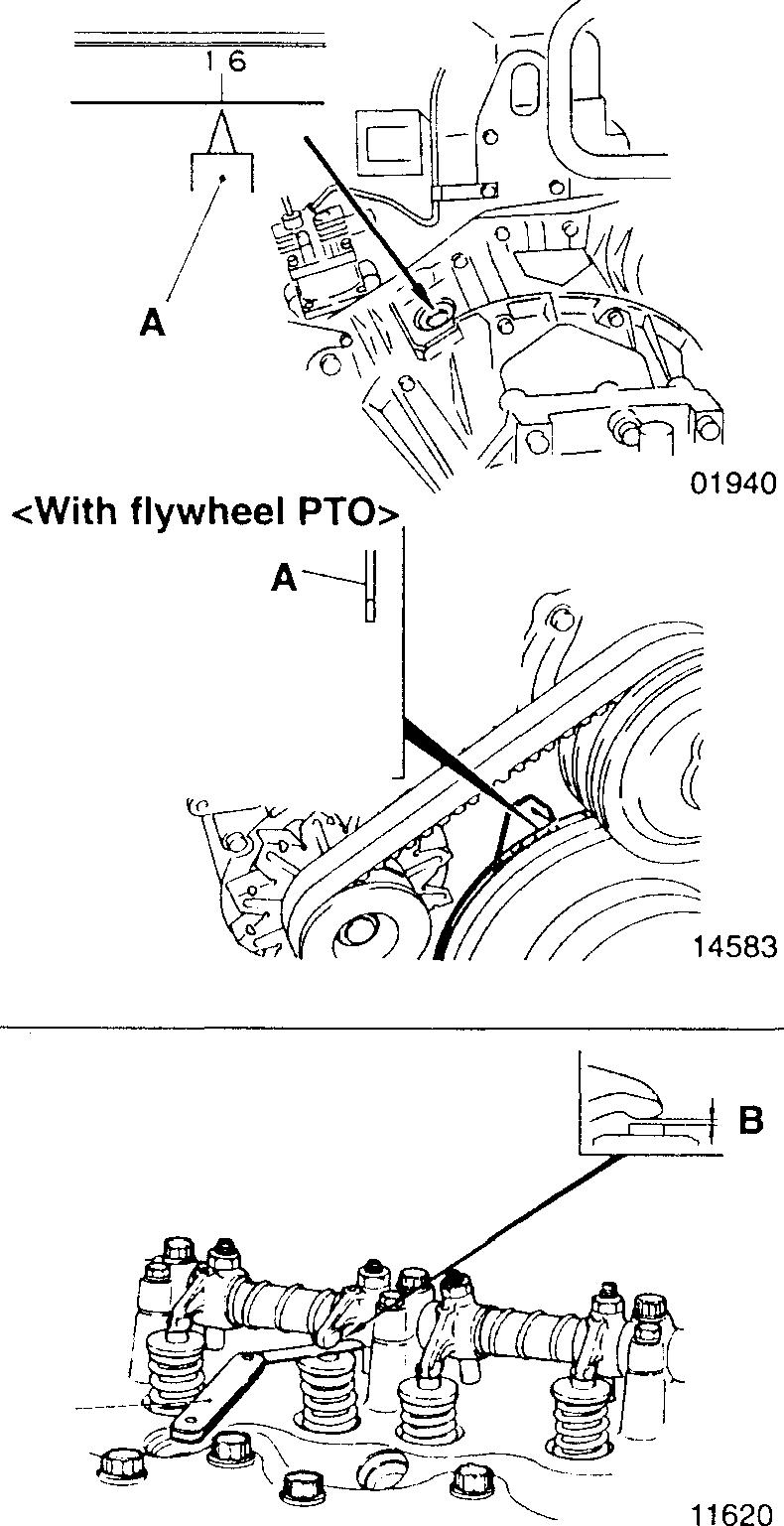
[Inspection]
• BringpistonNo. 1 orpistonNo.6tothetop-dead-centre(TDC)position of its compression stroke. To do this, crank the engine until the "1.6" mark inscribed on the flywheel is aligned with the pointer A in the flywheel housing inspection window. (If the engine has a flywheel PTO, alignthepointerAwiththe"O''markinscribedonthetorsionaldamper.)
NOTE
Pistonswhosepushrodsare notpushinguptheir rockers areat top-dead-centre (TDC) of their compressionstrokes.
• WhenpistonNo. 1 orpistonNo.6isattheTDCpositionofitscompressionstroke,measuretheclearance8ofeveryvalvemarked"O"inthe followingtable.
PistonNo. 1 2 3 4 5 6
Valvearrangement In.Ex.In.Ex.In.Ex.In.Ex.In.Ex.In.Ex.
No.1pistonatTDCofcom- (J 0 0 X X 0 0 X X 0 X X pressionstroke
No.6pistonatTDCofcom- X X X 0 () X X 0 0 X 0 0 pressionstroke
NOTE
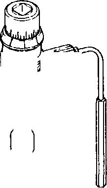
To measure the clearance, insert a feeler gauge 1. The gauge should be able to move in the gap, albeit not loosely. Accurate measurementscannotbetakenifthegaugemoveslooselyinthe gap.
Tightening
OZ:- OL-0 -----1L1J..JIIJ!ll1111I I 11-10
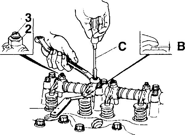
• If any measurementis out of specification, make adjustments as follows:
[Adjustment]
• Toadjustthevalveclearance B, loosenthelocknut2andturntheadjustingscrew3 until the feelergauge 1 movesmore stiffly in the gap.
• Afteradjusting the clearance, tighten the lock nut 2. At this time, use ascrewdriverCtostoptheadjustingscrew3fromturning. Next,insert thefeelergauge1 oncemoretoconfirmthattheclearanceB iscorrect.
Mitsubishi 6D16TLEA 6D16-TLEA
engine parts contact:
Email: EngineParts@HeavyEquipmentRestorationParts.com
Alternate email: engineparts2@gmail.com
Phone: 269 673 1638
Text: 269 760 8652
Fax: 269 673 7226
Heavy Equipment Restoration Parts 4730 118th Ave
Fennville Michigan 49408 USA
www.HeavyEquipmentRestorationParts.com
11621 11
ll-ll
Mitsubishi 6D16TLEA Tadano Crane
CYLINDER HEAD AND VALVEMECHANISM

• Disassembly sequence
1 Joint
2 Oil fillercap
3 Bolt
4 Plate
5 Rubber
6 Rocker covergasket
7 Rockercover
• Assembly sequence
A8 Cylinderheadbolt
9 Rocker and bracket assembly [D P.11-16
10 Cylinderheadandvalveassembly[D P.11-20
11 Cylinderhead gasket
Followthe disassembly sequence inreverse
12 Push rod
13 Tappet
*:Crankcase [D P.11-72
A: Locating pin
0:Non-reusablepart 04134
11-12
Mitsubishi 6D16TLEA Tadano Crane
- 0.4 Replace
Tappet-to-crankcase Replace clearance
0
Tightening torques
N·m {kgf·m} Location Parts to be tightened
torque Remarks
1 Joint 29 {3.0) -
3 Rockercoverbolt 3.9 {0.4) -
8 Cylinderhead bolt (installation of rock- M14 bolt 78 {8} + 180°
Wet er and bracket assemblyandcylinder
• Can be reused headandvalve assembly) upto 3times
M10bolt 17 {1.75) + 34 {3.5} -
� Oils
Location Pointsofapplication Kinds
2 Rubberseal of oil fillercap
8 Threads of cylinder head bolts
12 Both ends of pushrods
13 Outersurfacesoftappets
� Special tools
Engine oil Engine oil Engine oil Engine oil
Part No. Application
��t>'
01984
MH061560 Tighteningcylinderheadbolts (M14 bolt only)
♦ Service procedure
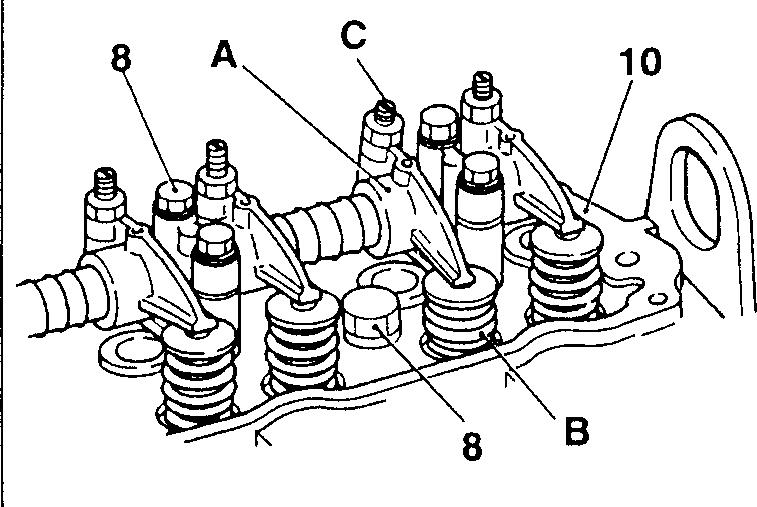
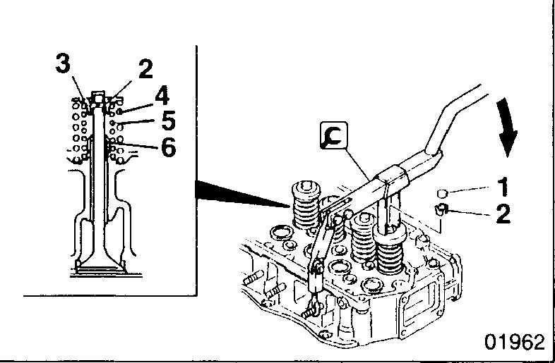
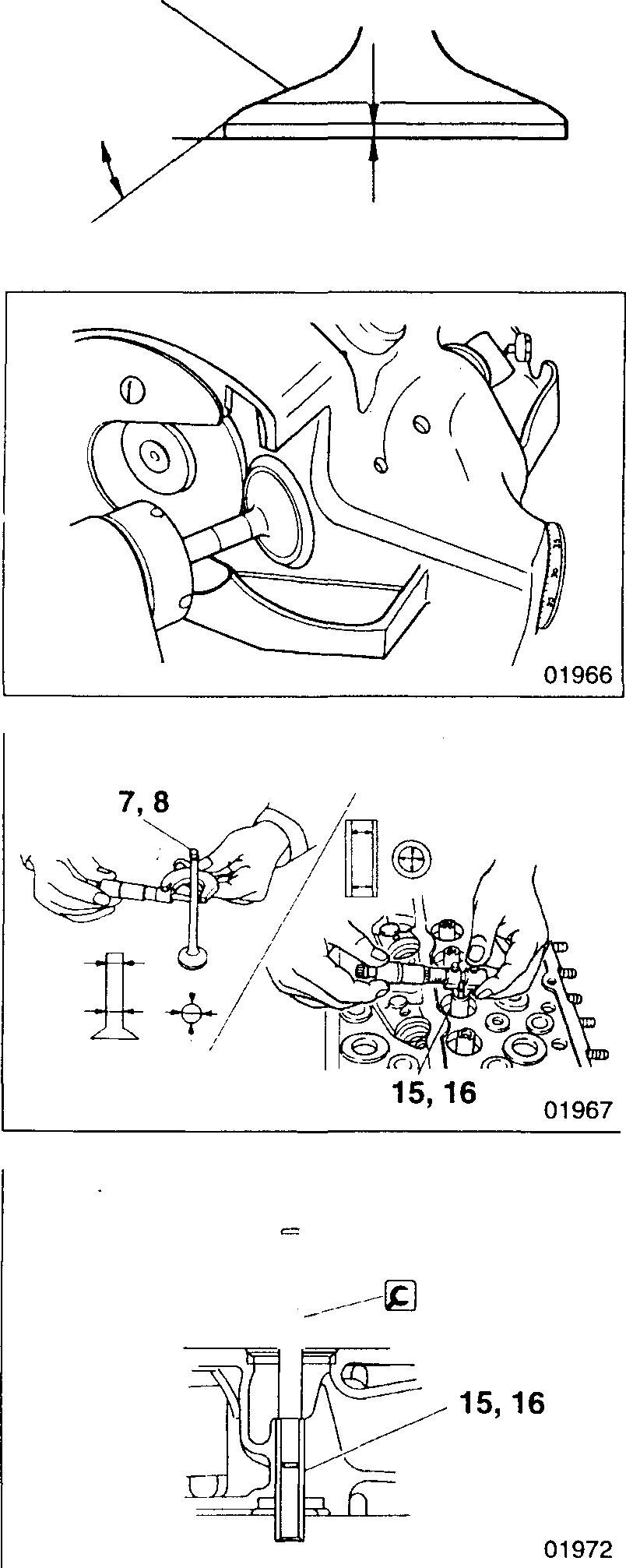
[!QI Cylinder head and valve assembly (Removal]
• Beforelooseningthecylinderheadbolts 8, loosentheadjustingscrew C on every rocker A that iscompressing its valve spring 8.
11 Service
Unit:
Standard
Remedy (Basic diameter
12
13,*
6D16-TLEA [31] 0.03to
0.1 tappet
standards
mm Location Maintenance item
value Limit
in [ ])
Pushrodrunout
0.07
Tightening
Unit:
•
Quantity
Location Tool
and shape
name
10 Socket Wrench ,_, �� ----13021
As
As required As required As
required
required
ll-13
Mitsubishi 6D16TLEA Tadano Crane
CYLINDER HEAD AND VALVEMECHANISM
• Loosen and remove the cylinder head bolts 8 in the sequence shown. Each cylinder head bolt should be loosened a little at a time.
[Fitting]
• The M14 cylinder head bolts 8 can be reused only three times. Before refitting the cylinder head bolts, make a punch mark on the head of each one to indicate times of reuse.
CAUTION&_--------------
lf any bolt alreadyhasthree punch marks, it mustnot be reused any more; replace itwithanew one.
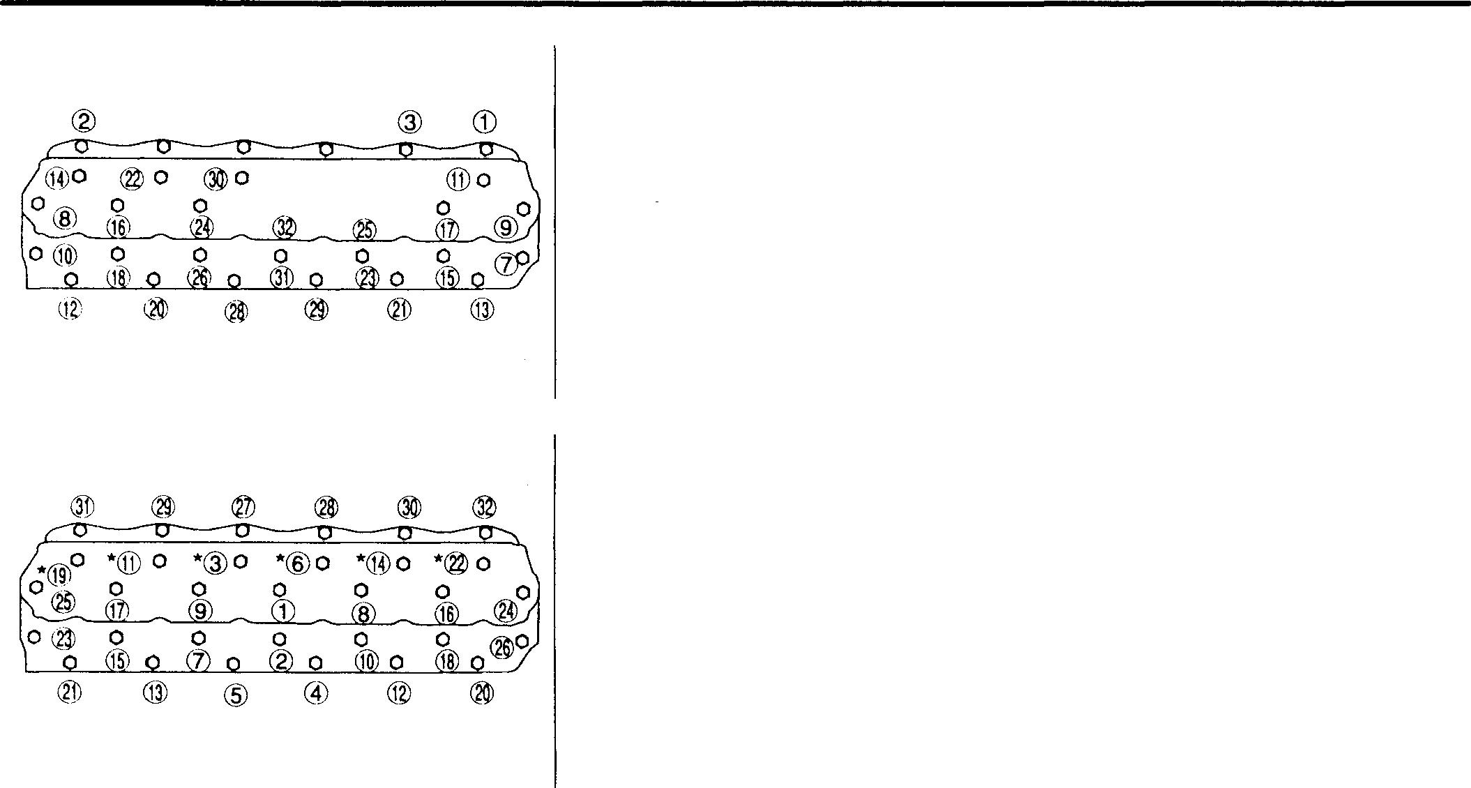
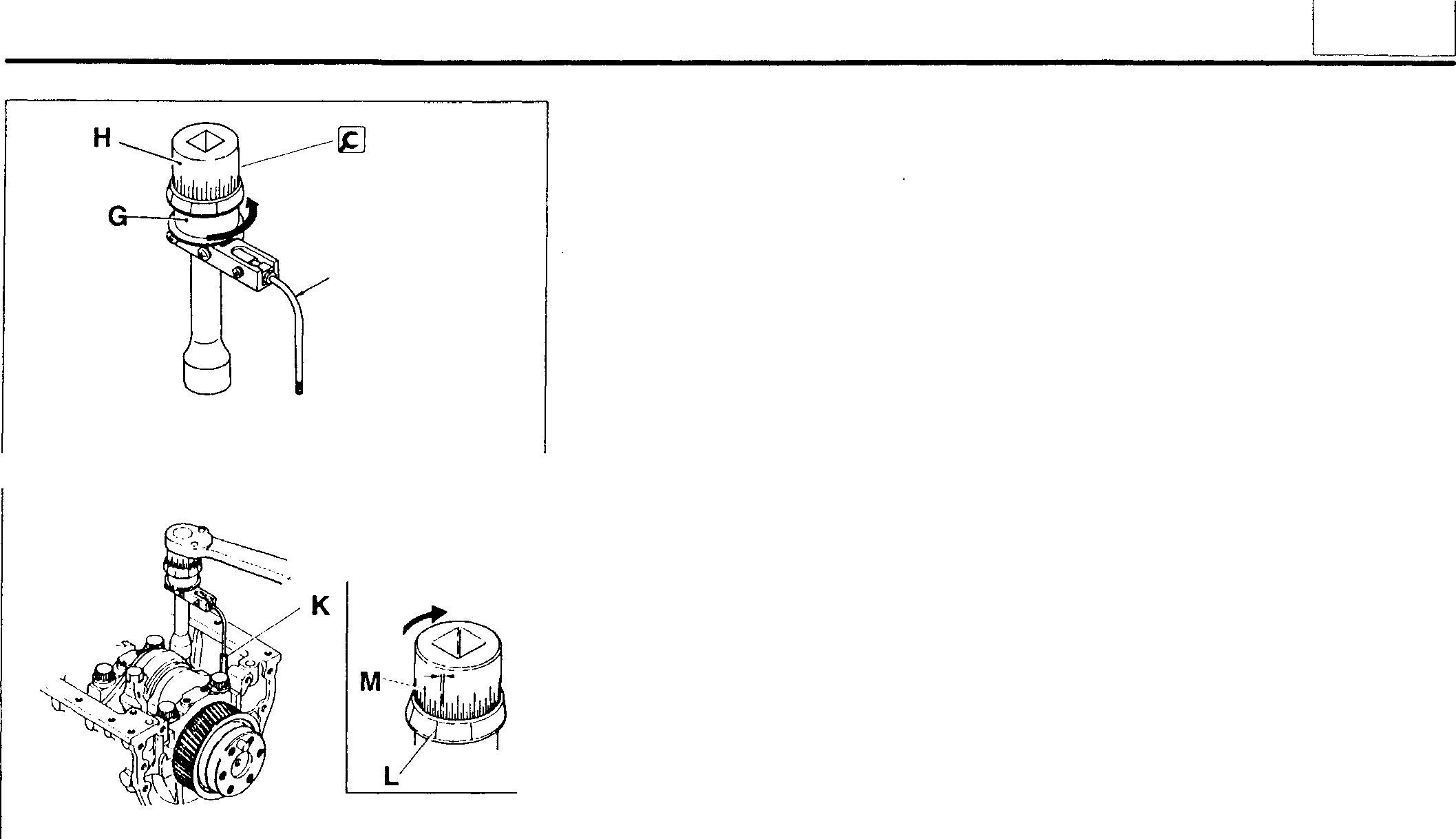
• Tightenthecylinderheadbolts8 tothespecifiedtorque (M14 bolts: 78 N·m {8 kgf·m}; M10 bolts: 17 N·m {1.75 kgf·m}) in the sequence shown. Then, turn the bolts further in accordance with the following procedure.
*: Tighten together with rocker and bracket assembly
G) to®: M14 bolt (wet)
® to®: M10 bolt
<M14 Bolts>
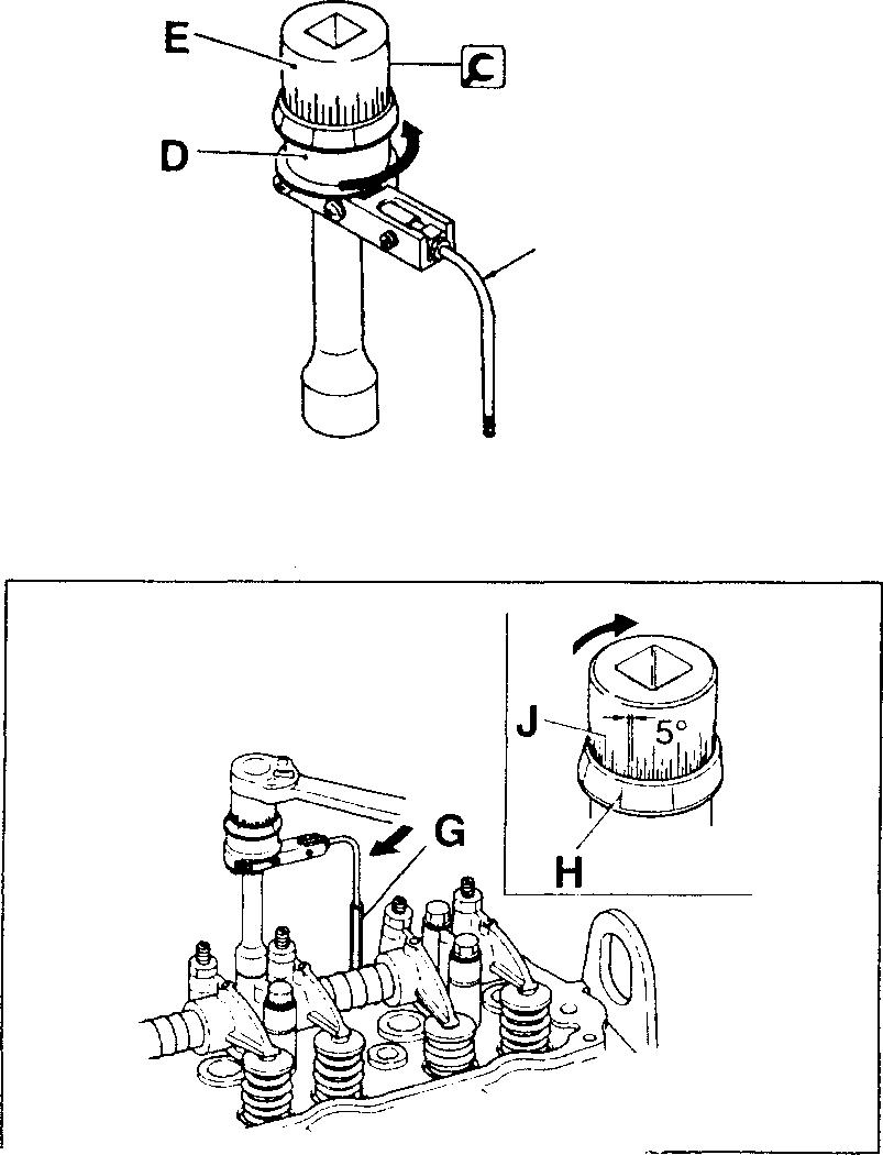
• Beforefitting the I&] Socket Wrench over a cylinder head bolt, turn the holder D counter-clockwise to tension the built-in spring.
E: Socket
F: Rod
G: Rod (extension)
• Set the socket such that the built-in spring force forces the rod G against the rocker shaft bracket, an injection pipe, or another nearby part.
• On the holder D, select the inscribed line H that is easiest to see.
• Using the selected line as a reference, turn the socket E 180° clockwise. (One gradation on the scale J represents 5°.)
CAUTION&_-------------
SincetheM14cylinderheadbolts8utilizetheplasticregiontighteningmethod,theymustnotbetightenedfurtherafterthisprocedure.
@ @ 11-14 @ @o @o 0 0 F tG 01945 01945 � 01991 12825
<M10 Bolts>
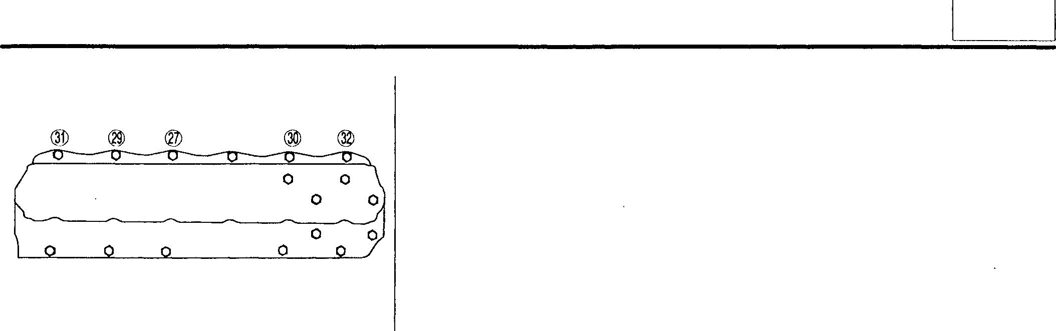
• After fitting theM14 cylinder head bolts8, tighten the M10 bolts to the spencified torque (34 N ·m {3.5 kgf ·m}) in the sequence shown.
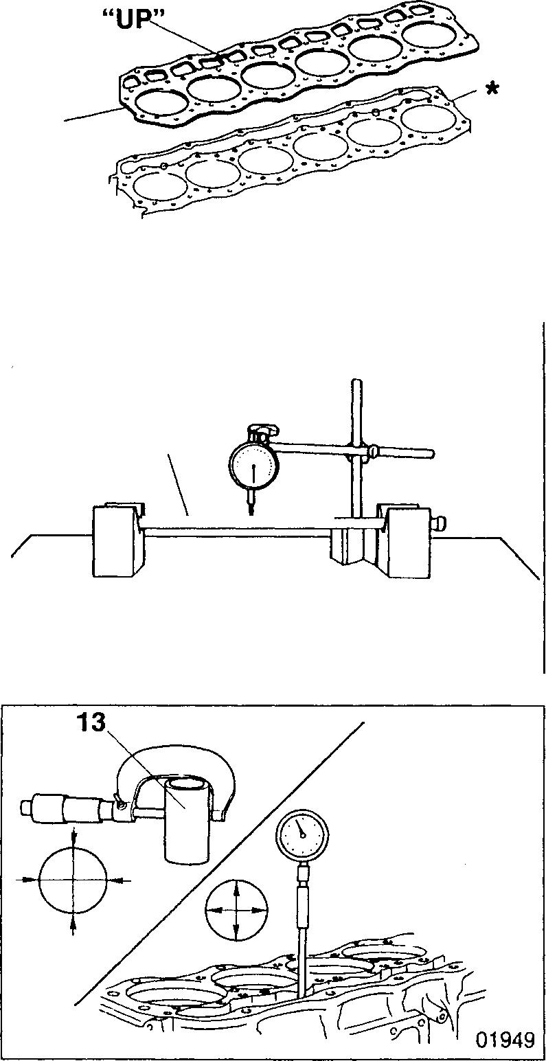
[TI] Cylinder head gasket [Removal]
CAUTION_&.-------------
When removing the cylinder head gasket 11, be careful not to scratch the cylinder head and valve assembly 10 and the crankcase*·
[Fitting]
• Fit the cylinder head gasket 11 onto the crankcase* as shown.
01948
� Push rod runout
If any measurement exceeds the specified limit, replace the defective part(s).
�G Tappet-to-crankcase clearance
If any measurement exceeds the specified limit, replace the defective part(s).
® 0 0 0 0 0 0 0 0 0 0 0 0 0 11 12 0 0
01945 13582
11
Jl-15
Mitsubishi 6D16TLEA Tadano Crane
CYLINDER HEAD AND VALVE MECHANISM
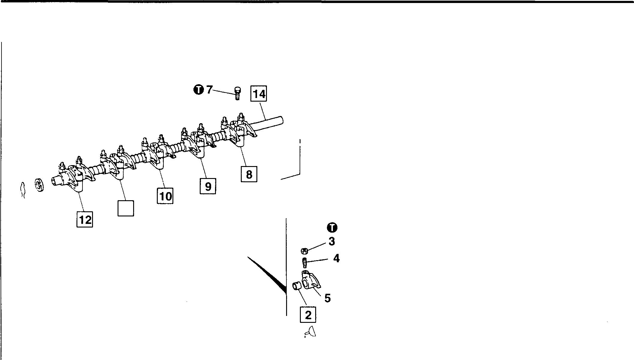
Rocker and Bracket Assembly
Service standards
13 6
Location Maintenanceitem
2, 14 Rocker bushing-to-rockershaftclearance
0
Tightening torques
Location Partsto betightened
3 Adjustingscrewlocknut
7 Rockershaftsetscrew
� Oils
Location Pointsof application
2 Rockerbushinginnersurface
� Special tools
Location 2
Rocker Bushing Puller
Toolnameand shape
• Disassembly sequence
1 Rockerassembly
2 Rocker bushing
3 Lock nut
4 Adjustingscrew
5 Rocker
6 No. 6 rocker shaft bracket
7 Setscrew
8 No. 5 rocker shaft bracket
9 No. 4 rocker shaft bracket
10 No. 3rocker shaft bracket
11 No. 2rockershaft bracket 12 No. 1 rocker shaft bracket 13 Rocker shaft spring
Rockershaft
• Assembly sequence
1 01951
11 1 ! L\,�fiL��·
11-16
14
Reverse
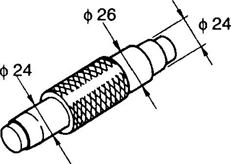
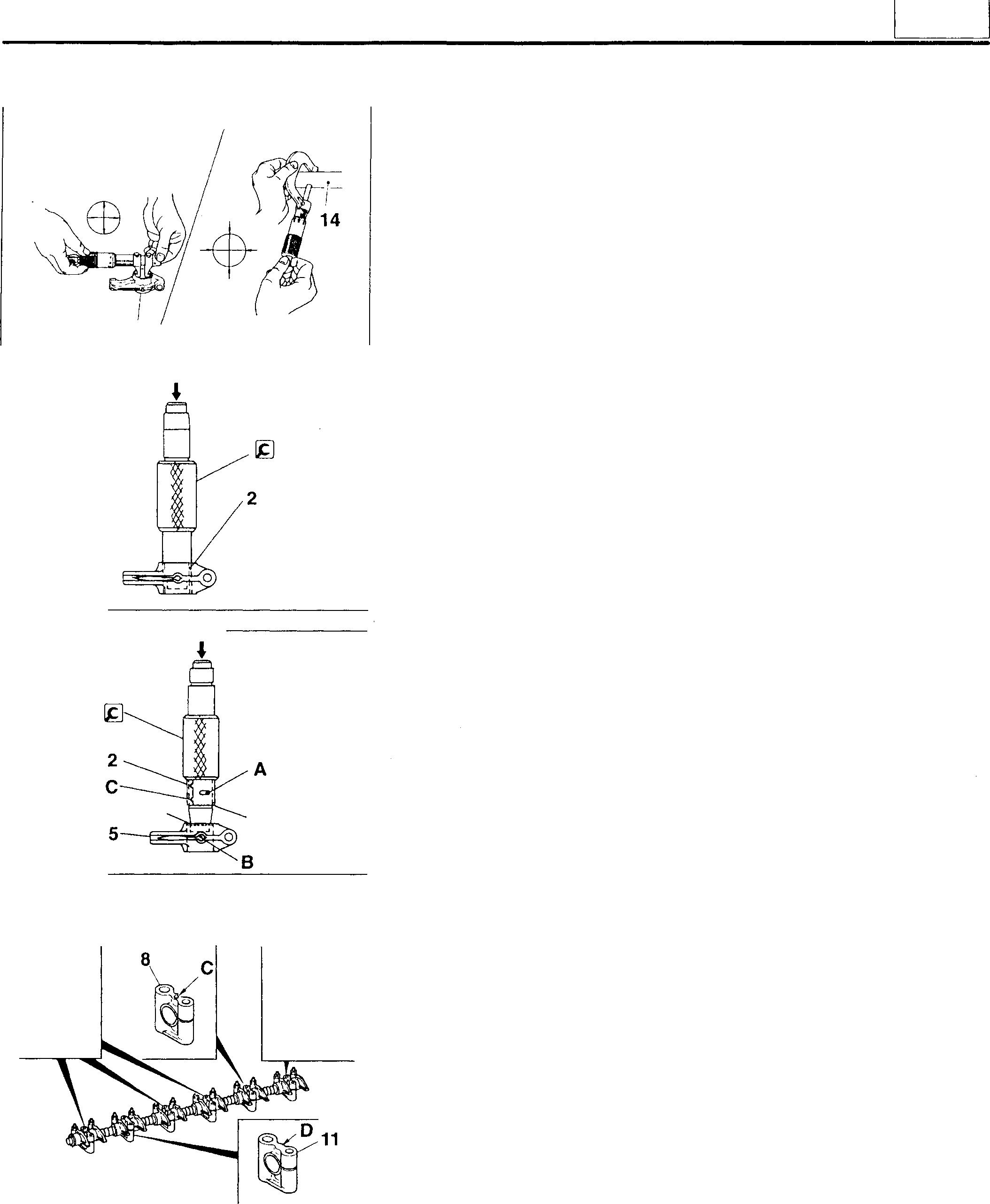
ofdisassembly. 13022 Unit: mm Standard value Limit Remedy (Basicdiameterin []) [24]0.01 to0.08 0.12 Replace Unit: N·m {kgf·m} Tighteningtorque Remarks 34{3.5}3.9{0.4}Kinds Quantity Engineoil Asrequired Unit: mm Part No. Application MH061777 Removingand installingrocker bushings
theorder
9, 10, 12�8
A�
♦ Service procedure [I]� Rockerbushingandrockershaft
[Inspection]
Ifanyclearanceexceedsthespecifiedlimit, replace thedefective part(s).
Rocker bushing [Removal]
[Installation]
• AligntheoilholeAintherockerbushing2withtheoilhole B intherocker 5.
• Position the notch C and seam D on the rocker bushing 2 as shown.
• Install the rocker bushing 2 into the rocker 5 from the chamfered side F.
� [fil to� � Installingrockershaft bracketsandrockershaft
Rockershaftbrackets
Be sure to fit the rocker shaft brackets 6,8, 12 in their correct positions.
A: Oil hole
B: Threaded hole (for MS rocker cover bolt)
C: Threaded hole (for M6 set screw)
D: No threaded hole
2 01952 12994 D 12995
s�8
13023
11
11-17
CYLINDER
HEAD AND VALVEMECHANISM
Rocker shaft
H 4
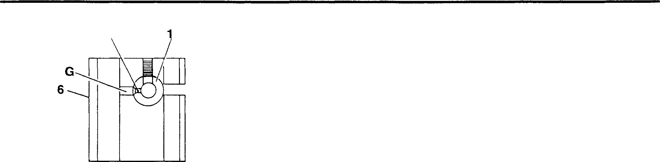
Align the oil hole G in the No. 6 rocker shaft bracket 6 with the oil hole H in the rocker shaft 14.
11-18
13024
11 I
11-19
MEMO
Mitsubishi 6D16TLEA Tadano Crane
CYLINDER HEAD AND VALVEMECHANISM
Cylinder Head and Valve Mechanism
<Without glow plug>
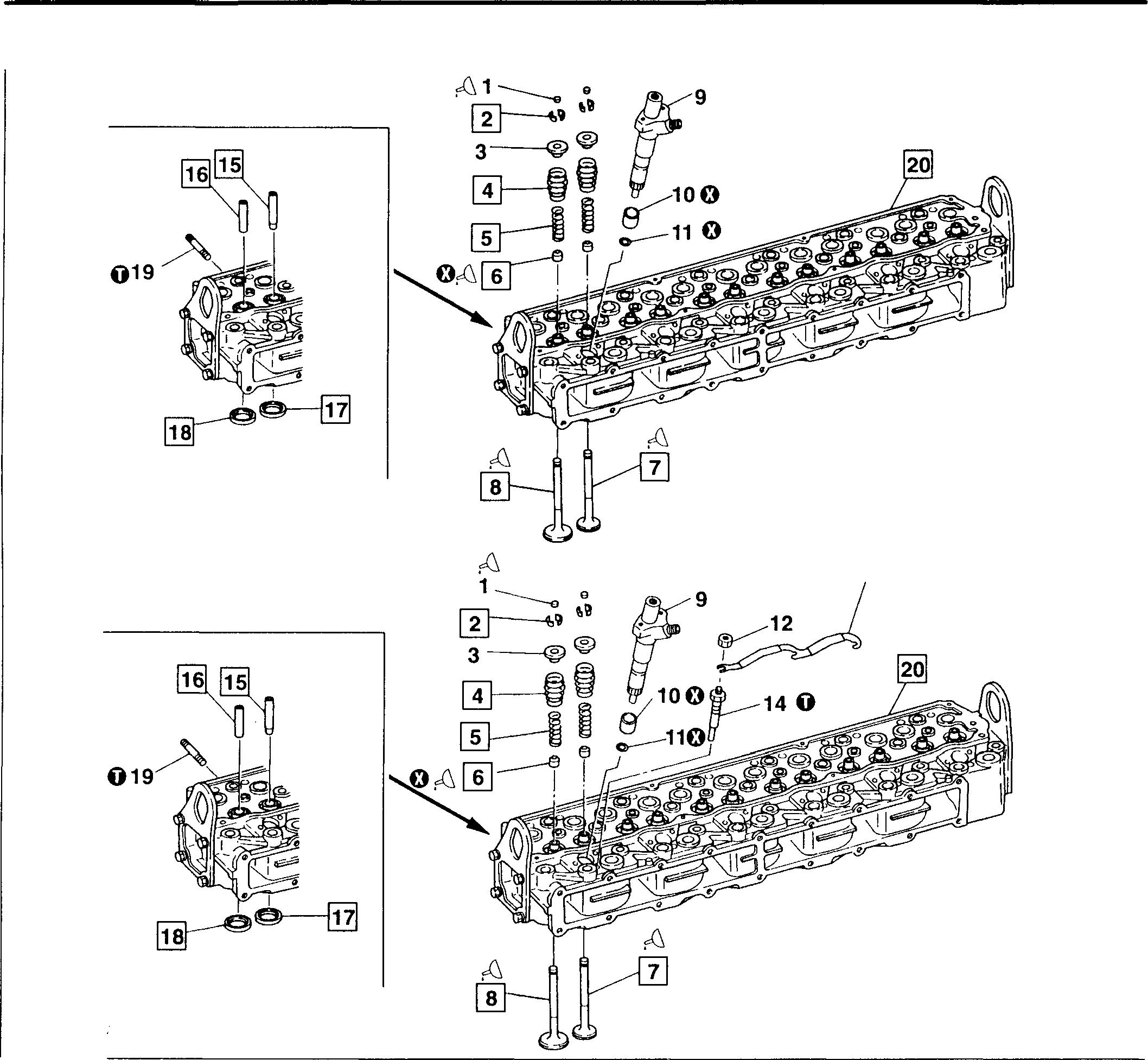
<Withglow plug>
• Disassembly sequence
CAUTION.&,------------------
Theinjectionnozzles9andglowplugs 14projectfromthebottomsurfaceofcylinderhead20.Takecarenotto damage them.
• Assembly sequence
Follow the disassembly sequence in reverse.
NOTE
Any valve stem seal 6 removed froman exhaust valve7or inletvalve8must bereplaced.
1
2 Valve
3 Upper retainer 4 Outer valve spring 5 Inner valve spring 6 Valve stem seal 7 Exhaust valve 8 Inlet valve 9 Injection nozzle ITTGr 13 10 Dust seal 11 Nozzle tip gasket 12 Nut <With glow plug> 13 Connecting plate <With glow plug> 14 Glow plug <With glow plug> IT]Gr54 15 Exhaust valve guide 13 16 Inlet valve guide 17 Exhaust valve seat 18 Inlet valve seat 19 Stud 20 Cylinder head 0
Non-reusable part 20300 01955
Valve cap
cotter
:
11-20
Mitsubishi 6D16TLEA Tadano Crane
11 Service standards Unit: mm Location Maintenance item Standard value Limit Remedy (Basic diameter in [ ]) Outer Free length 67.0 64.0 Replace valve 68.3 65.3 spring Installedload 330 N{33.5kgf} 290 N Replace 4 (at 47.8 installed {29.7 kgf} length) 390 N{40.0 kgf} 350 N {35.5 kgf} Squareness - 2.5 Replace Inner Free length 55.1 52.1 Replace valve 65.1 61.5 spring Installedload 92 N {9.4kgf} 78 N Replace 5 (at 40.5 installed {8.0 kgf} length) 155 N {15.8kgf} 130 N {13.4kgf} Squareness - 2.0 Replace - 2.5 Exhaust Stemoutsidediameter <j> 8.93to 8.94 <j> 8.85 Replace valve Sinkage from cylinder head bottom sur- 1.3to 1.7 2.0 Inspect evface ery location 7 Valvemargin 1.5 1.2 Reface or replace Seat angle 45° - Correct Inlet Stem outsidediameter <P 8.96to 8.97 <1> 8.85 Replace valve Sinkage from cylinder head bottom sur- 1.1to 1.5 1.8 Inspect evface ery location 8 Valvemargin 1.5 1.2 Reface or replace Seat angle 45° ± 15' - Correct 7,15 Exhaustvalve stem-to-valve guide clearance [9) 0.07to 0.1o 0.2 Replace 8,16 Inletvalve stem-to-valve guide clearance [9) 0.04to 0.06 0.15 Replace 17 Exhaust valve seat width 1.8 to 2.2 2.8 Corrector replace 18 Inlet valve seat width 1.8to 2.2 2.8 Correct or replace Cylinder Bottomsurface distortion 0.08 orless 0.2 Correct or 20 head replace Height from top to bottom surface 94.9to 95.1 94.5 Replace
Unit: N·m {kgf·m} Location Parts to be tightened Tightening torque Remarks 14 Glow plug <With glowplug> 15to 20 {1.5to 2.0)19 Exhaustmanifoldmountingstud 29 {3}11-21
0 Tightening torques
L=67 L=68.3 L-55.1 L=65.1 L=55.1 L=65.1
CYLINDER HEAD AND VALVE MECHANISM
� Oils
Location Pointsof application
1 Rocker contactsurfaceonvalvecap top
6 Lip·ofvalve stem seal
7,8 Valve stem
[&] Specialtools
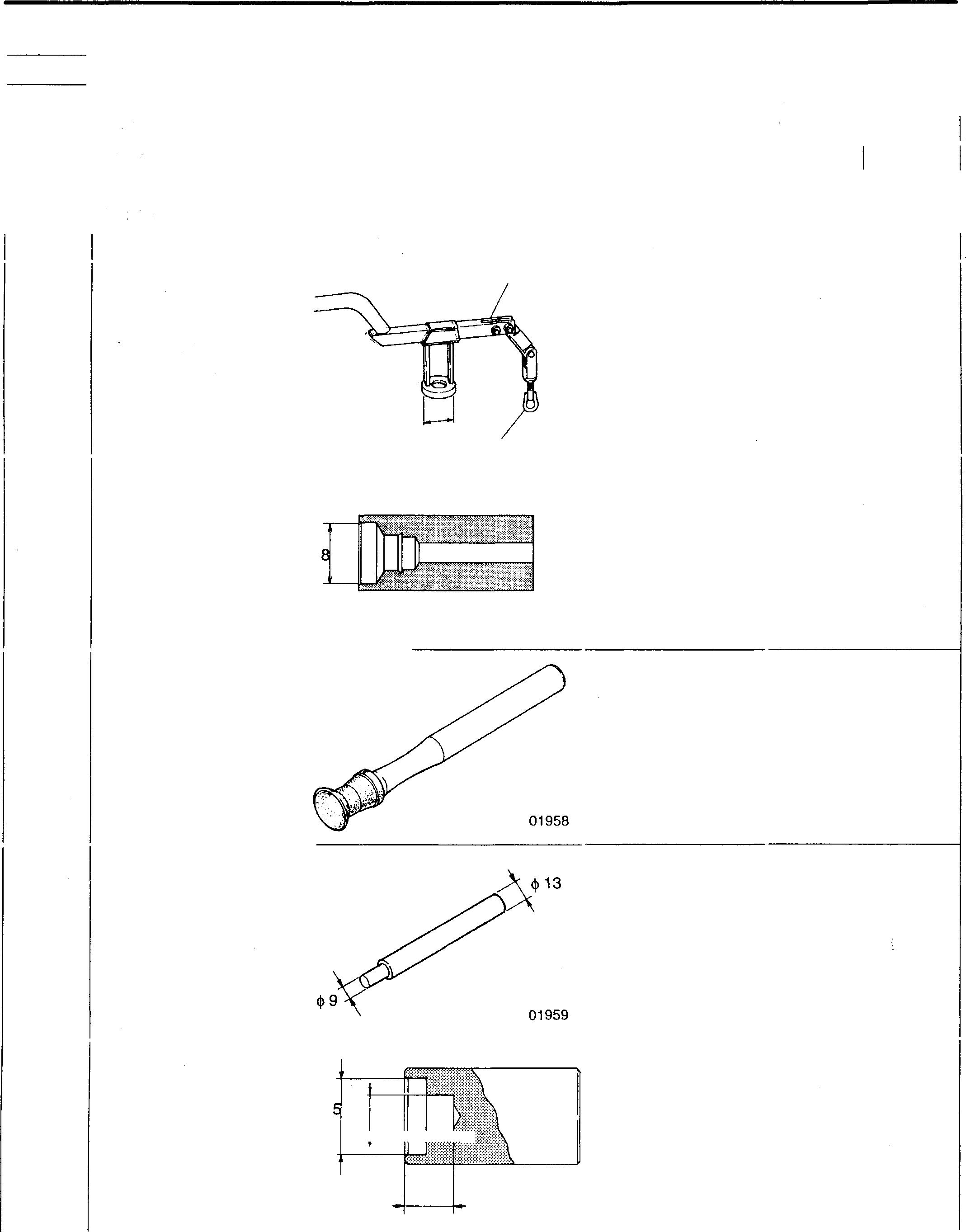
A: ValVBLifter
B: Yi!llMeLitterHook
Tool name and shape
Part No.
A: MH001668 (withqi42 valvelifter seat)
B: MH061679
Removingandinstalling valvecotters
Valve Stem Seal Installer qi2
Valve Lapper
Valve Guide Remover
Valve Guide Installer 15t--\t-+�hI?
9 MH061293 01957
Installingvalvestem seals
30091-07500 (inlet, exhaust)
Lappingvalvesand valveseats
MH061066 (inlet, exhaust)
Removingvalveguides
MH061998
Installing inlet andexhaustvalveguides
Location 2 6
ll-22
7,8 15,16
qi42 qi28. qi
18 A B
Engineoil
oil 01956
Kinds Engineoil
Engine
=+qi
01960
Quantity Asrequired Asrequired Asrequired Unit: mm Application
Mitsubishi 6D16TLEA Tadano Crane
Location 17, 18
A: Caulking Tool Body
B: Installer Ring
� C dimension
MH061695 <1> 49
t=3···
MH061696 <j>42 <1> 9
MH061693 <1> 51
MH061694 <j>44
�r ~
'"mmdl-
B A 01961
♦ Service procedures
[]] Valve cotters
[Removal]
Toremovethevalvecotter 2, usethe�Valve Liftertoevenly compress the valve springs 4, 5.
[Installation]
Toinstall valve cotters, followtheremoval instructions in reverse.
CAUTION&--
Do not compress the valve springs 4, 5 more than is necessary. Ifthevalvespringsarecompressed excessively, theupperretainer 3 can touch the valve stem seal 6 and be damaged.
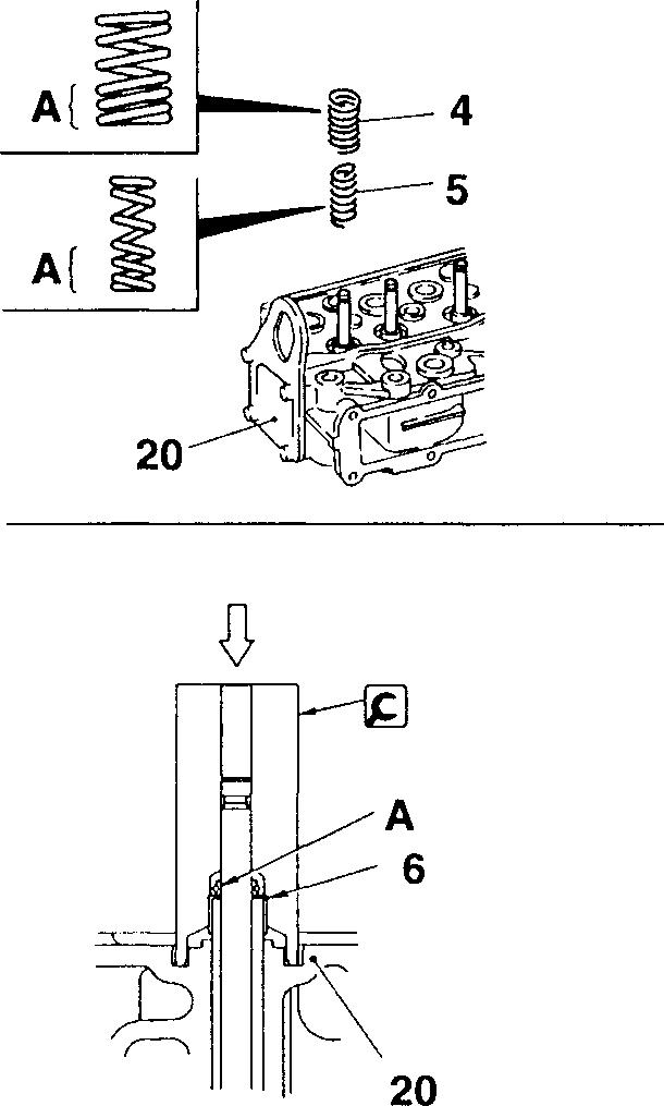
[!] [fil Installing outer and inner valve springs
Fit the outer andinnervalvesprings4, 5 onto the cylinder head 20with theirpainted ends downward.
A: Painted end
11641
01964
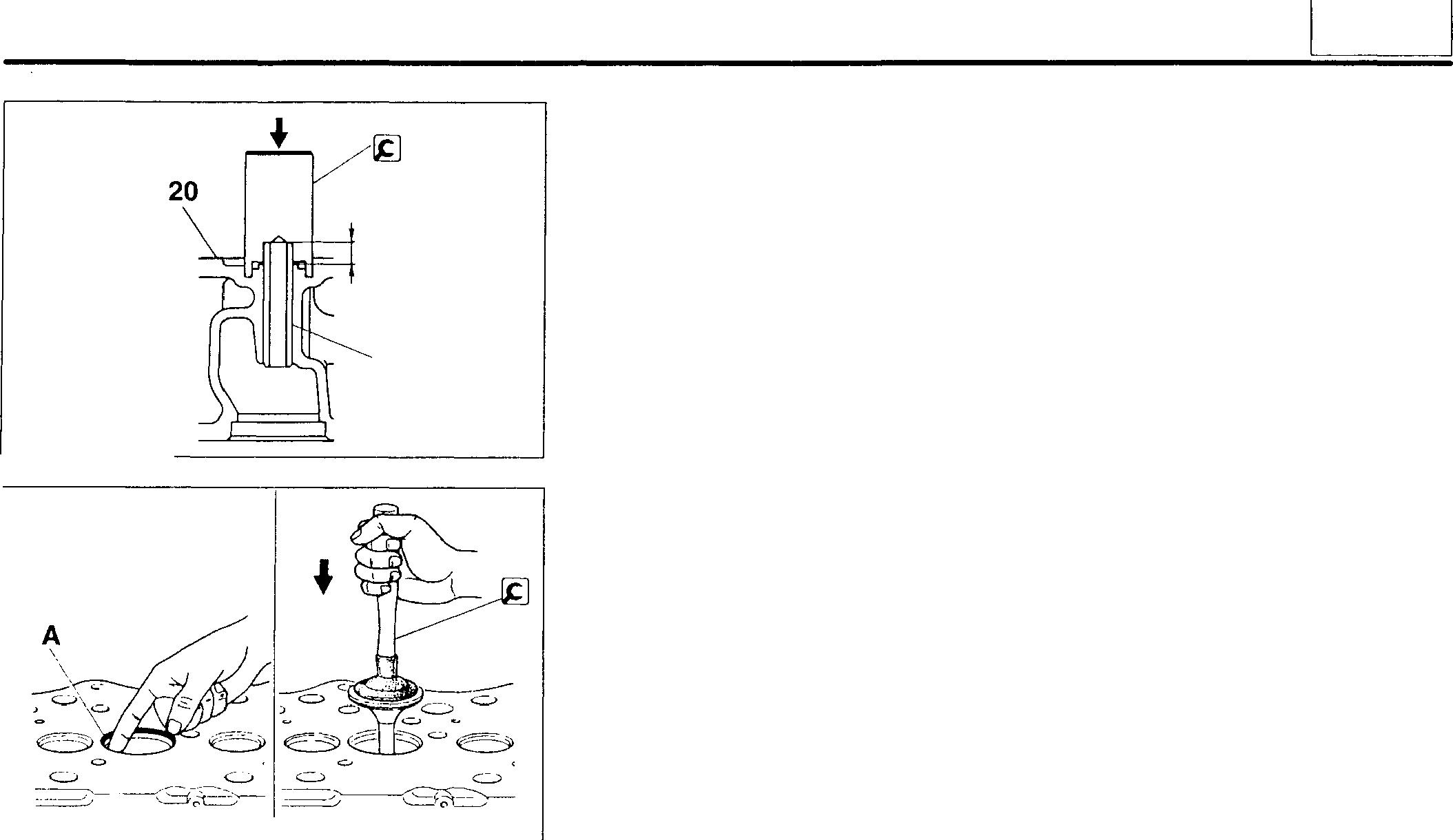
[fil Installing valve stem seals
• Apply engine oil to thelip A of thevalve stem seal 6.
• Install the valve stem seal 6 using the� Valve Stem Seal Installer. Strike the Valve Stem Installer until it sits snugly onthecylinderhead 20.
11
name and shape
Application
Tool
Part No.
�
Ff
Installing valve seats
C
11-23
CYLINDER HEAD AND VALVEMECHANISM
[I]I]] Valve
(Inspection]
(1)Valve stem outside diameter
Replacethevalve 7, 8 ifitsstem'soutsidediameterisbelowspecificationor severelyworn.
CAUTION_&.-------------
Whenever a valve7, 8 is replaced, be sure to lap the valve and valve seat 17, 18. Cll P.11-25.
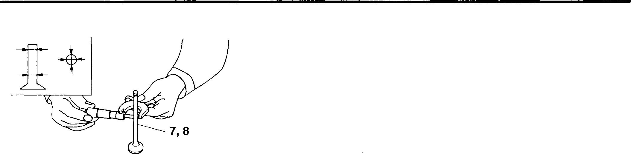
(2) Valve seat angle and valve margin
Refaceorreplacethevalve 7, 8 ifthevalveseatangleorvalvemargin exceedsthe specifiedlimits.
A: Valve seatangle
B:Valve margin
(Rectification)
NOTE
• Keep grinding to a minimum.
• If the valve margin is below specification after grinding, replace the valve 7, 8.
• After grinding, be sure to lap the valve and 7,8 valve seat 17, 18. Cll P.11-25
[I]I]]�[RI Valves and valve guides
[Inspection)
Ifanyclearanceexceedsthespecifiedlimit,replacethedefectivepart(s).
Valve guides
[Removal]
01965 7,
A B 02264 • 11-24
8
Mitsubishi 6D16TLEA Tadano Crane
[Installation]
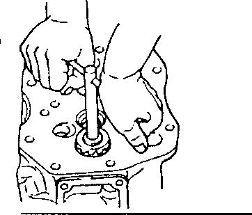
Installthevalveguide15,16usingthe�Valve GuideInstaller. Strikethe Valve GuideInstaller untilit sits snugly on the cylinderhead20.
CAUTION&--------------
• Thevalveguides15,16must be pressed intothespecifieddepth. Be sure to use the � Valve Guide Installer for this operation.
• Exhaust valve guides15arelonger thaninlet valve guides16. Be sure to install the correct type of guide in each location.
12] [fil � [Thi Valves and valve seats
[Inspection]
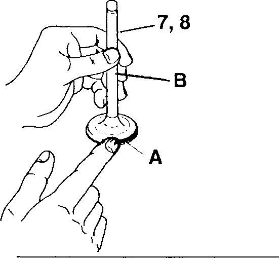
• Apply aneven coat of minium to the valve seat 17, 18surface A that makescontactwith thevalve7, 8.
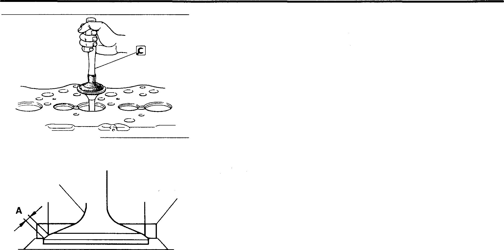
• Using the�Valve Lapper, strike thevalve 7, 8against the valve seat 17, 18once. Do not rotatethe valve during this operation.
NOTE
Carryouttheseinspections after inspecting thevalvesand valve guides.
• Iftheminiumdepositedonthevalve7, 8 indicatesapoorcontactpattern, rectifythe contact pattern as follows:
Contact Corrective action
Minordefect Lapping
Serious defect Refaceor replace valve and valve seat
[Refacing]
Lapthevalve in accordancewith the following procedure:
• Apply a thin, even coat of lapping compound to the surface A of the valve 7, 8thatmakescontactwith the valve seat 17, 18.
CAUTION&--------------
Ensure that no compound adheres to the stem B of the valve 7, 8.
NOTE
• Start with intermediate-mesh compound (120to 150mesh) and finish with fine-mesh compound (200mesh or more).
• The addition of a small amount of engine oil makes lapping compound easier to apply.
18mm 15,16 02220 01968 000 '----y---J '-----,y�---__, 0 X
11
01969 01970
ll-25
CYLINDER HEAD AND VALVE MECHANISM
• Usingthe�ValveLapper,lightly strikethevalve7,8againstthevalve seat17, 18 while turningitlittle by little.
• Wash away thecompound with gasoilor asimilar fluid.
• Applyengineoiltothecontactsurfacesofthevalveseat17,18andrub itinsothatthecontactsurfacesarelubricatedandmatetogethersnugly.
• Inspectthecontactpatternofthevalve7,8andvalveseat17,18once more.
• Ifthe contact patternis stilldefective, replacethevalve seat17, 18.
[izl� Valveseats
[Inspection]
(1) Valveseatwidth
If the measurement exceedsthe specifiedlimit, rectify or replace the valve seat17, 18.
A:Valve seatwidth
NOTE
Wheneveravalveseat17,18isrectifiedorreplaced,besureto lap thevalveseatandvalve7,8. m P.11-25
(2) Valve sinkagefrom cylinderhead bottomsurface
7,8
Ifany measurementexceedsthespecifiedlimit, rectify orreplacethe defectivepart(s).
B:Valvesinkage
[Rectification]
• Grindthevalveseat17,18usingavalveseatcutterorvalveseatgrinder.
• Aftergrinding,putsomesandpaperofaround#400gradebetweenthe cutter and valve seat andgrind thevalve seatlightly.
• Usea 15° or 17° cuttertoachievethe specified valve seat widthA.
C:Valveseatangle
CAUTION&--------------
.Ensure that grinding does not cause the valve sinkage B to exceedthespecified limit.
• After rectification, lapthevalve7,8 andvalve seat 17, 18. m P.11-2s
c:.:, ----- �71 7,8 17,18 01975 7,8 17,18 B 02265 �c N,,\
01977 11-26
Mitsubishi 6D16TLEA Tadano Crane
17, 18
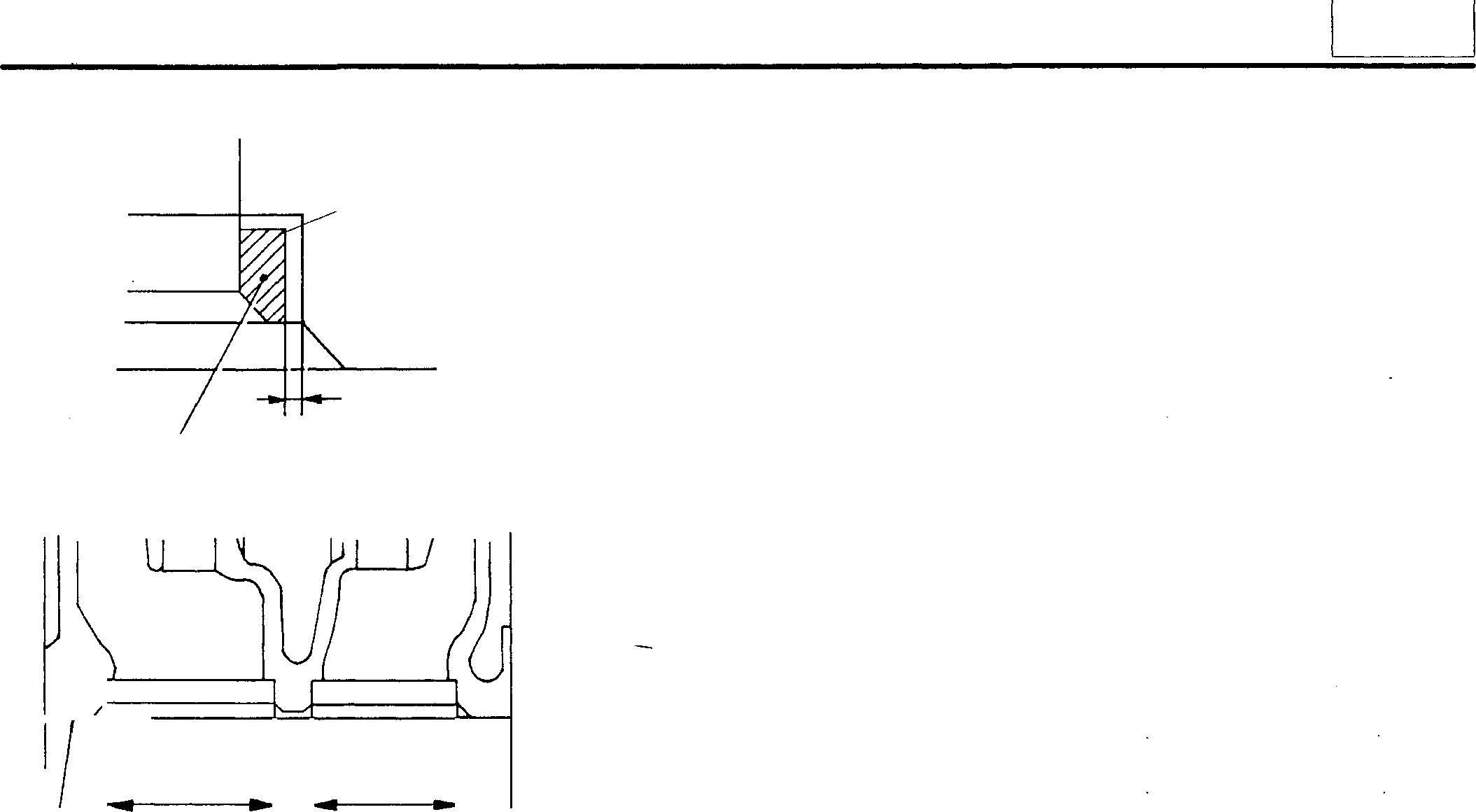
D 0.5 to 1.0 mm
[Removal]
Valve seats 17, 18 areinstalled by expansion fitting. To remove a valve seat, grind the inside surface to reduce its thickness, then remove the valveseatatroomtemperature.
D: Materialto remove
[Installation]
• Checkthatthevalveseathole diameters E, Finthecylinderhead 20 conform with the values shown below.
Early type Late type
Inlet valve seat hole (E)
+ �025
Exhaust valve seat hole (F)
+ �025
Unit: mm
+ �03
+ �025
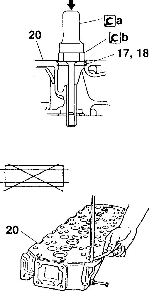
• Coolthe valveseat 17, 18 by immersing itin liquid nitrogen.
• Installthevalveseat 17, 18 inthecylinderhead 20 usingthe©aCaulkingTool Body and ©b Installer Ring.
• Afterinstallingthevalveseat 17, 18, lapthevalveseatandvalve 7, 8. OJ P.11-25
� Inspecting cylinder head
• Measuretheextentofdistortioninthecylinderhead's bottomsurface.
• Ifthedegreeofdistortionexceedsthespecifiedlimit,rectifythedistortion with asurface grinder.
CAUTION&_-------------
Ensure that grinding does not cause the cylinder head's top surface-to-bottom surface distance to fall below the specified limit.
01973 20
F 01976 01974 01978 11
E
---------
qi49
qi51
qi42
qi44
11-27
Mitsubishi 6D16TLEA Tadano Crane
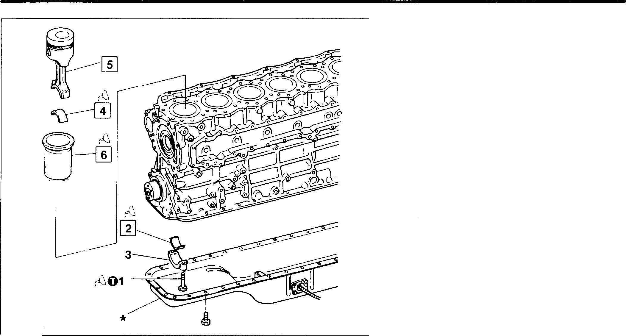
PISTONS, CONNECTING RODS, AND CYLINDER LINERS
• Pre-disassembly inspection OJ P.11-30
• Removal sequence
1 Bolt
2 Lower connecting rod bearing
3 Connecting rod cap
4 Upper connecting rod bearing
5 Piston and connecting rod assembly OJ P.11-36
6 Cylinder liner
*: Oil pan0JGr 12
• Installation sequence Reverse the order of removal.
16914
Service standards
Location Maintenance item
- Piston projection
Connecting rodend play 2,4 Connecting rodbearing Oilclearance Span when free
5,6 Piston andconnecting rodassembly-to-cylinderlinerclearance
6016-TLEA
6 Cylinder liner Flangeprojection Inside diameter

6D16-TLEA Cylindricity
6016-TLEA
11-28
Standardvalue Limit (Basic diameter in [ ]) 0.85to
0.15to 0.45 0.6 [65] 0.04to 0.09 0.2 - Lessthan 69.5-[118] 0.136to 0.1650.03to 0.10<I> 118to 118.03
0.03or lessUnit: mm Remedy Inspect eachloca!ion Replace Replace Replace Replace Replace Replaceor grind to oversize
1.06
q,118.25
Mitsubishi 6D16TLEA Tadano Crane
0
Tightening torques
Location Parts to be tightened
1 Bolt (connecting rodinstallation)
� Oils
Location Points of application
1 Boltthreads
2,4 Connectingrodbearing inside surface
6 Cylinder liner outside surface
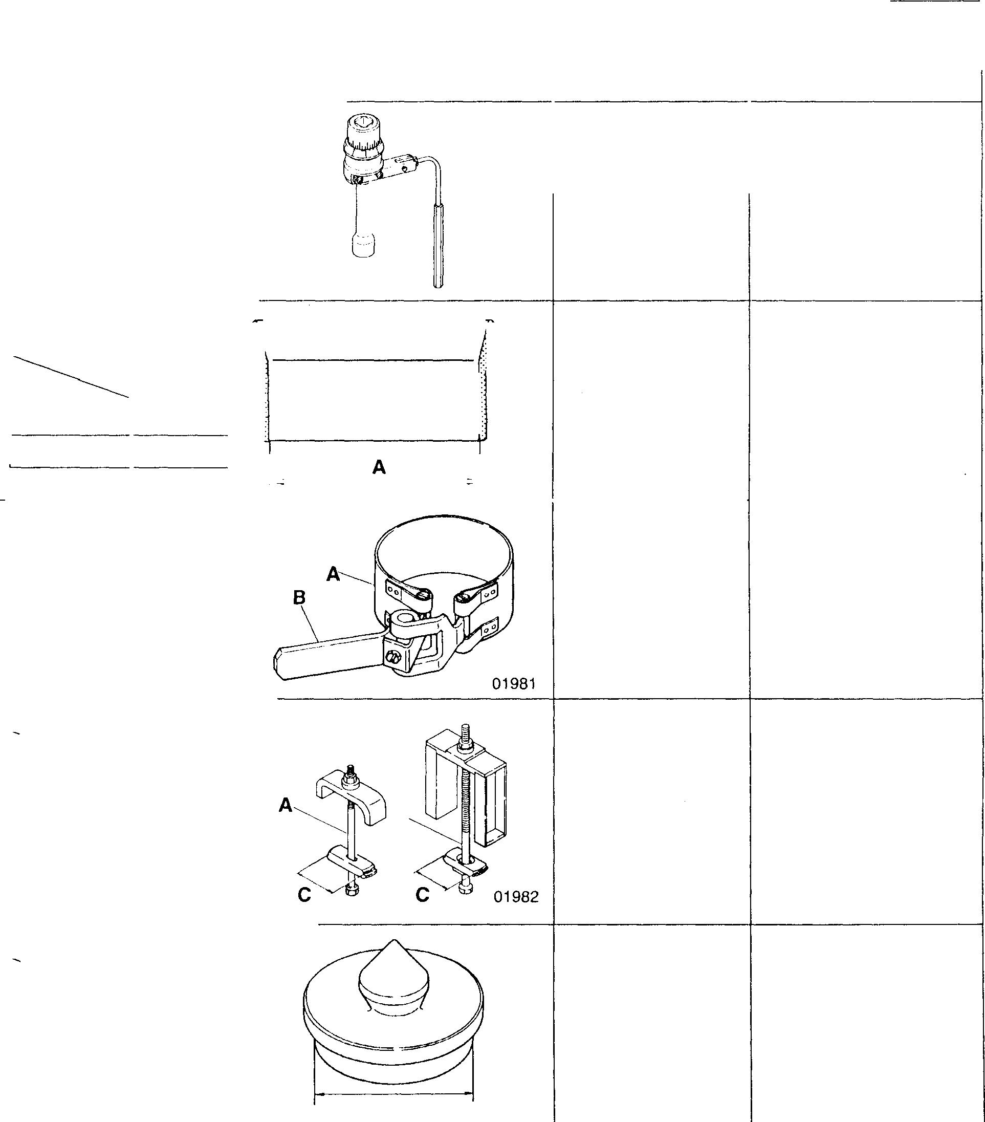
� Special tools
Location Tool name and shape
5 SocketWrench 1
5 A: PistonGuide Clamp
B: PistonGuide Lever
CylinderLiner Extractor
� C dimension <I> 117.5
6D16-TLEA
6 Cylinder Liner Installer
� A dimension qi 117.5
6D16-TLEA
Tightening torque
29 (3) +90° ±5° Kinds
Engine oil
Engineoil
Engineoil
Part No.
MH061560
01984 J 01983
6D16-TLEA A: MH061760 B: MH061658
Installing pistonand connecting rod assembly
Installing pistonand connecting rod assembly
Removing cylinder liners
6D16TLEA MH061761
6D16TLEA MH061771
Installingcylinderliners (dry type) 11-29
B A
11 Unit: N·m {kgf·m} Remarks Wet Quantity As required As required As required Unit: mm Application
Mitsubishi 6D16TLEA Tadano Crane
PISTONS,
CONNECTING RODS, AND CYLINDER LINERS
♦ Service procedure
• Pre-disassembly inspection
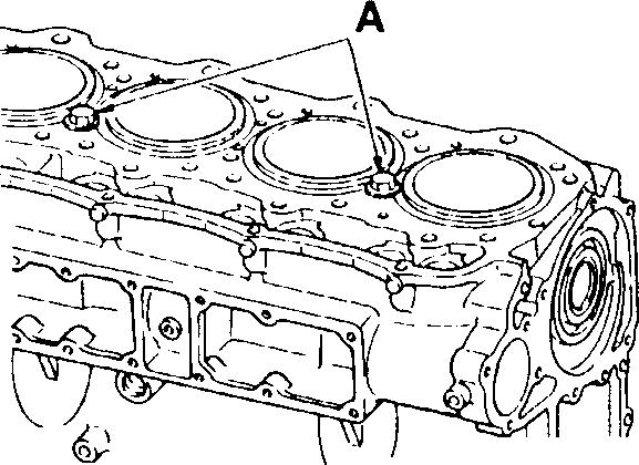
(1) Piston projection from crankcase top surface
NOTE
The piston projections affect engine performance and must therefore be checked.
WARNING_&------------
With 6D16-TLEA engines, the cylinder liners may rise out of position when the crankcase is turned over or the crankshaft is turned. Hold their flanges down using bolts and washers A.
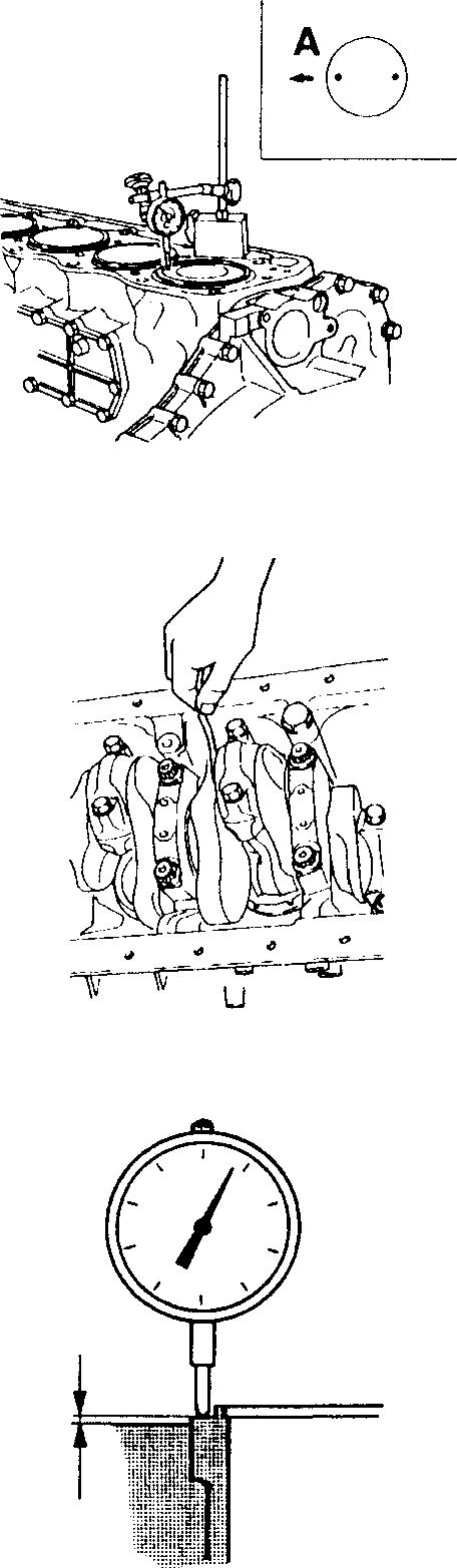
• Measuretheprojectionofeachpistonattwopointsandcalculatethe average of the two values.
A: Front of engine
• Ifthe average valueisout ofspecification, check theclearancesbetween all relevant parts.
(2) Connecting rod end play
• Measure the end play of every connecting rod.
• If any measurement exceeds the specified limit, replace the defective part(s).
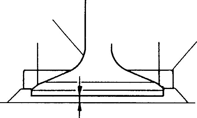
(3) Cylinder liner flange projection
If any measurement is out of specification, replace the defective part(s).
B : Flange projection
CAUTION&_-------------
lf the cylinder liner 6 flange projection is insufficient, bearing pressure on the cylinder head gasket will be too low in the region of the bore, possibly causing gas to leak.
01985
01986
B 01988 11-30
01987
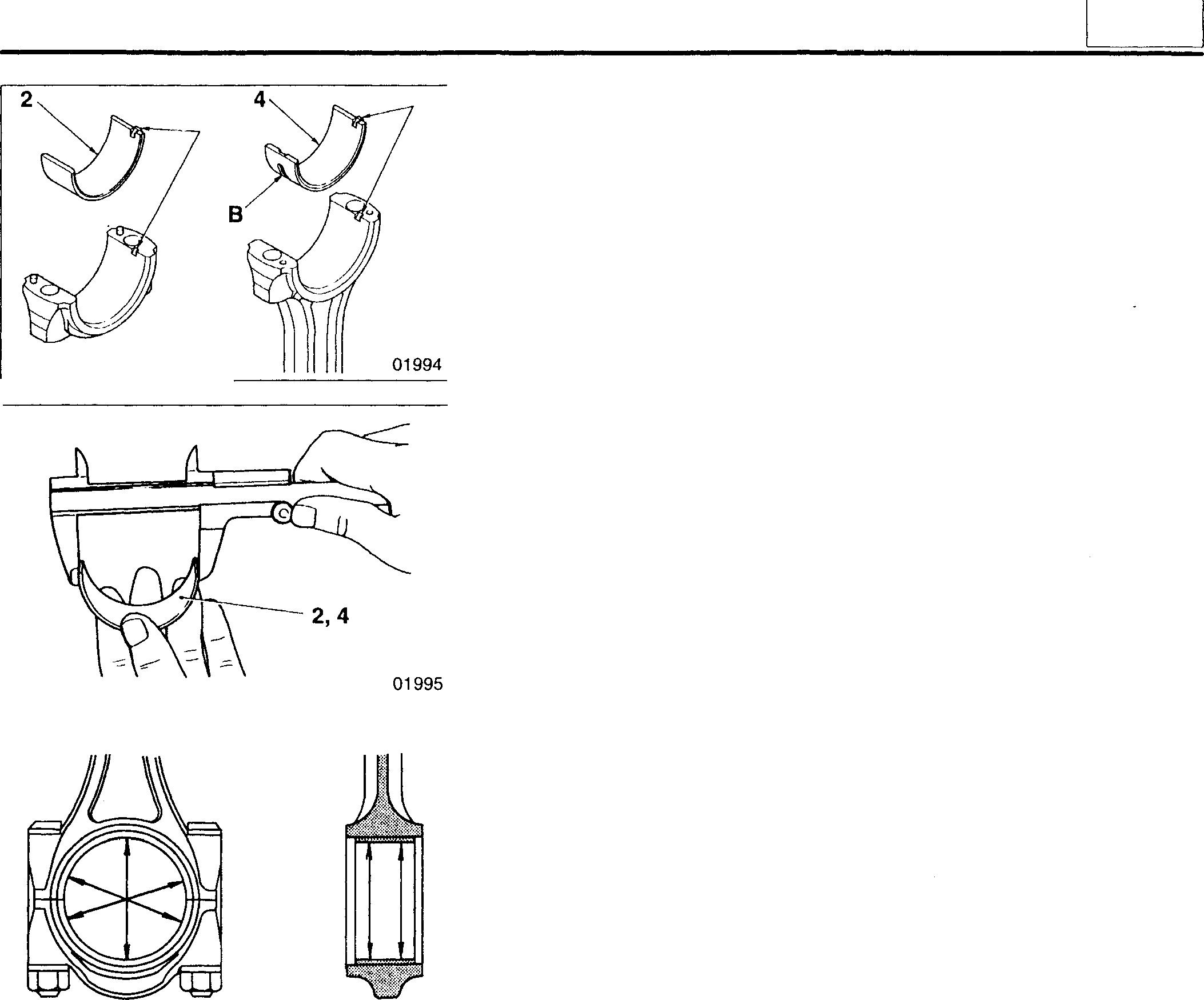
[I][II Connecting rod bearings
[Installation]
Installtheconnectingrod bearings2, 4byfitting the lugs Aintotheir respective grooves.
CAUTION&_-------------
The upper connecting rod bearing has an oil hole 8. The lower connecting rod bearing has no oil hole. Take care not to confuse the upper and lower parts.
[Inspection]
CAUTION&_--------------
• Do not attempt to manually expand a connecting rod bearing 2, 4 if its span is insufficient.
• Upper and lower connecting rod bearings 2, 4 must �e replaced as a set.
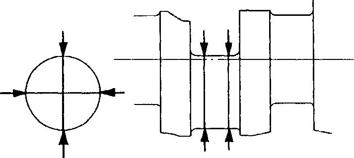
(1) Span when free
Ifthespanislessthanthespecifiedrequirement, replacetheupperand lower connecting rod bearings 2, 4 asa set.
(2) Connecting rod bearing-to-crankshaft pin clearance
Iftheconnectingrodbearing-to-crankshaftpinclearanceexceedsthe specified limit, replace the defective part(s).
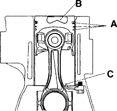
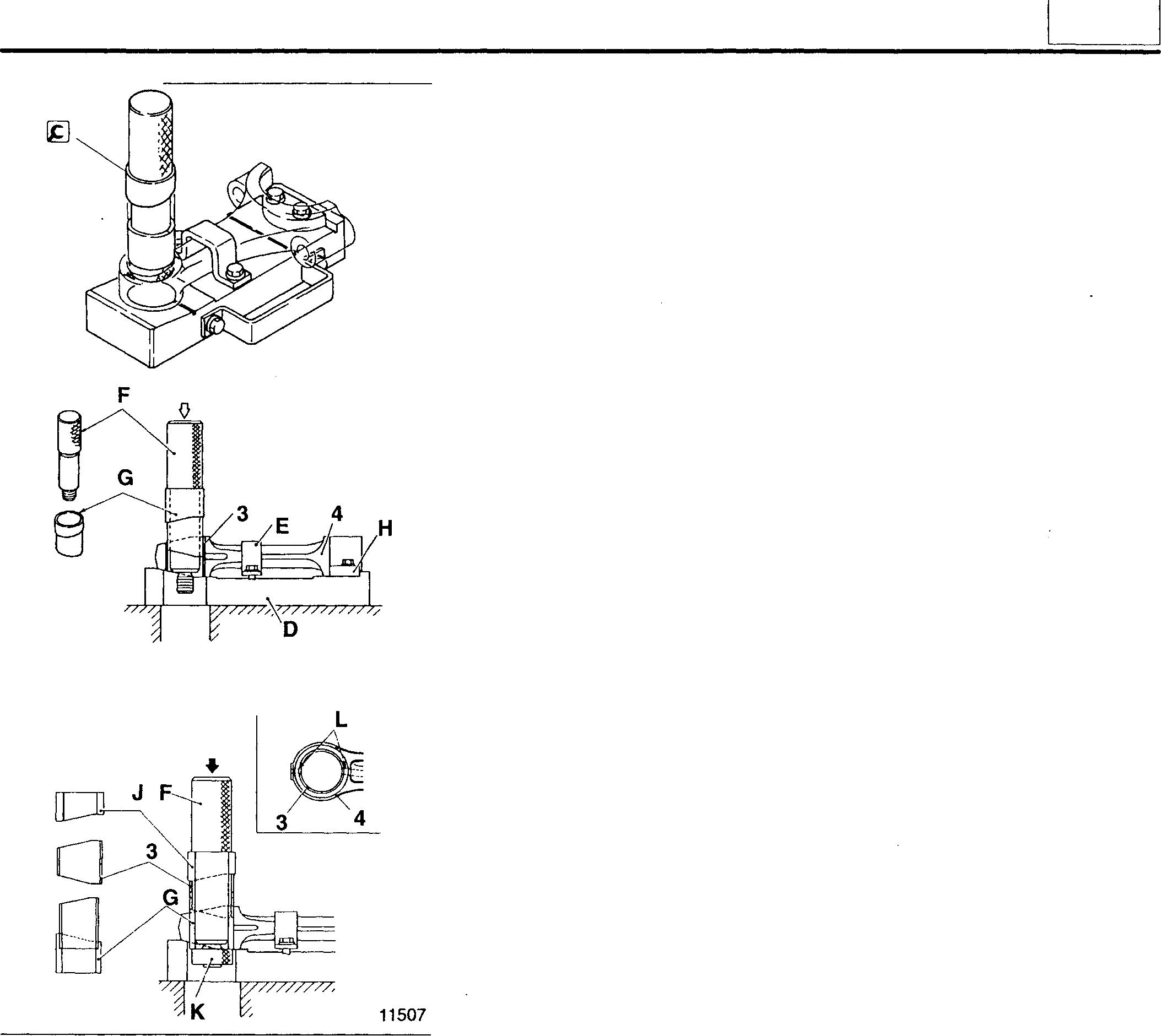
[]J Installing piston and connecting rod assembly
CAUTION&_-------------
• Ensure that the piston ring gaps A remain in their correct positions. [D P.11-41
• Take care not to damage the piston crown B (the area that forms part of the combustion chamber).
• Ensure that the connecting rod does not touch the oil jet C. 11-31
A A
11650
01996 01997
11
Mitsubishi 6D16TLEA Tadano Crane
PISTONS, CONNECTING RODS, AND CYLINDER LINERS
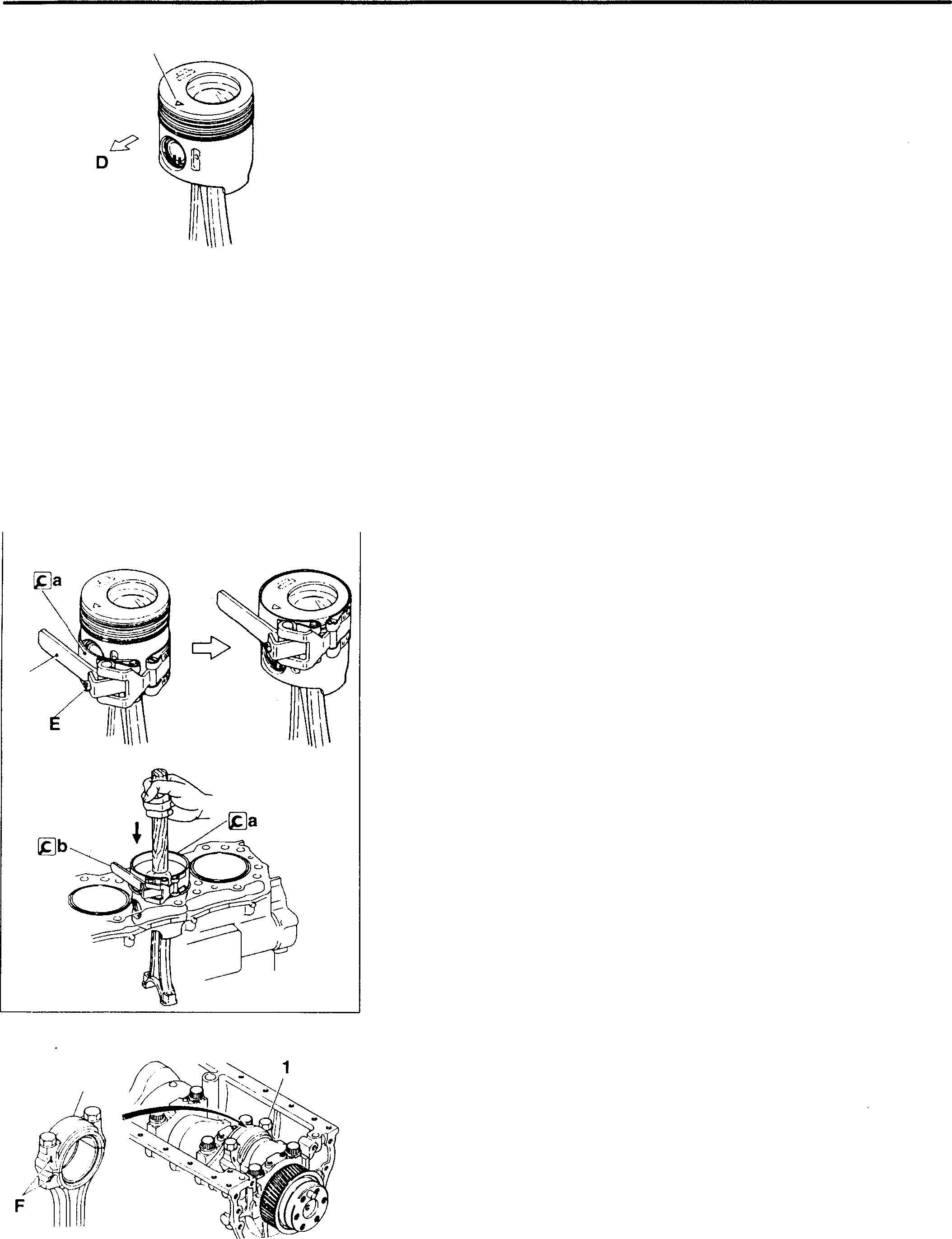
• Withthepiston's"!::,.''frontmarkfacingthefrontofthe engine, installthe piston and connecting rod assembly in accordance with the following procedure.
D:
Front of engine
< 6D16-TLEA
• Fit the [.ga Piston Guide Clamp over the piston skirt. Using the bolt E ofthe [.gb Piston GuideLever, adjusttheclamp'sinsidediametersuch that it matches the piston's outside diameter.
• Move the [&Jc Piston Guide Clamp and [.gb Piston GuideLever to the top of the piston.
• With the piston installed, align the mating marks Fon the connecting rod and connecting rod cap 3 and tighten the bolts to the specified torque. Then, tighten the bolts 1 further in accordance with the following procedure.
1gb 3 11-32
",6.11
03384
02009
11651
02011
01990
• Beforefittingthe�SocketWrenchoverabolt,turntheholderGcounter-clockwise to tensionthe built-in spring.
H:Socket
J: Rod
K: Rod (extension)
• Setthesocketwrenchsuchthatthebuilt-inspringforceforcestherod Kagainst thecrankshaft.
• On the holder G, select the inscribed line L that is easiest to see.
• Usingtheselectedlineasareference,turnthesocketH90° ±5° clockwise. (One gradation onthe scale M represents 5°.)
NOTE
Afterfitting theconnectingrodcaps3, inspect the following items:
• Connecting rod end play ( CD P.11-30)
• Piston projections (CD P.11-30)
11652
J
�
tK
0199'
11
11-33
Mitsubishi 6D16TLEA Tadano Crane
PISTONS, CONNECTING RODS, AND CYLINDER LINERS
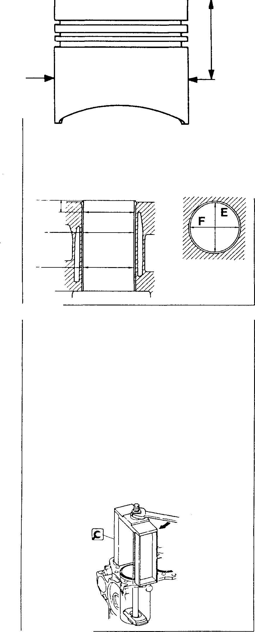
0• Check the piston-to-cylinder clerance.
<6D16-TLEA>
If any clearance isoutof specification, replace the defective part(s).
D:Outsidediameter measurementposition
E:Direction of crankshaft axis
F: Perpendicular to crankshaft axis
NOTE
The cylinder liners are of a thin design and cannot be bored to oversize dimensions. To prevent deformation of the cylinder liners, do not remove them except for replacement.
Cylinder liners [Removal]
NOTE
Ifanycylinderliner6mustbereusedafterremoval,makeanalignment mark with paint and use this mark to reinstall the cylinder liner in its original position.
185 mm or more 75 mm or more 20 mm or more I 6D16-TLEA > 11-34 75.1mm D 03375 02003 02000 02004
<6D16TLEA>
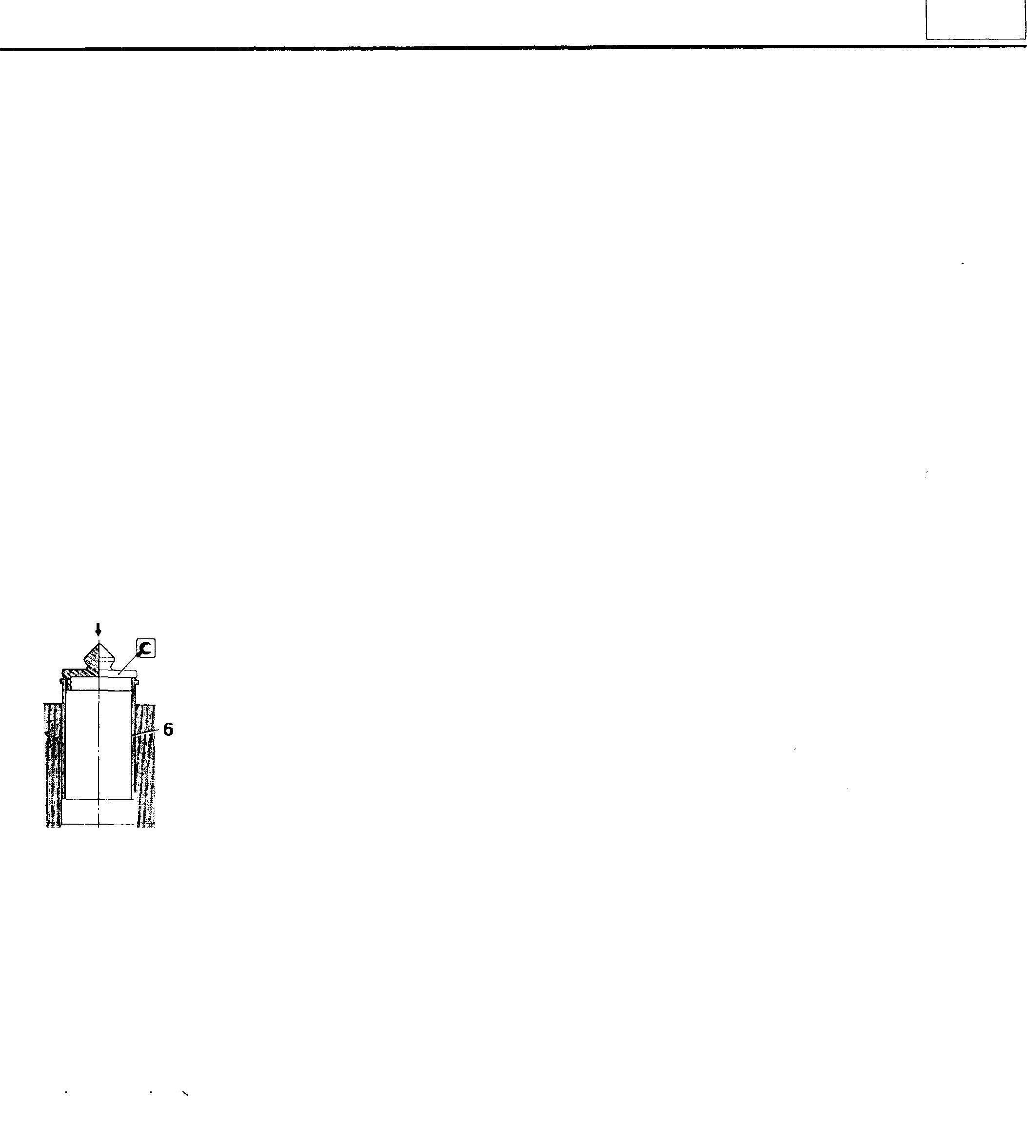
• Applyengineoiltothe outsidesurface ofthe cylinderliner 6.
• Insertthecylinderlinerintothecrankcaseandpressitintopositionusingthe�CylinderLinerInstaller. Pushdown evenlyontheentireupper surfaceoftheCylinderLiner Installer.
•
•
02007 11
11-35
Mitsubishi 6D16TLEA Tadano Crane
PISTONS, CONNECTING RODS, AND CYLINDER LINERS
Piston and Connecting Rod Assembly
• Disassembly sequence
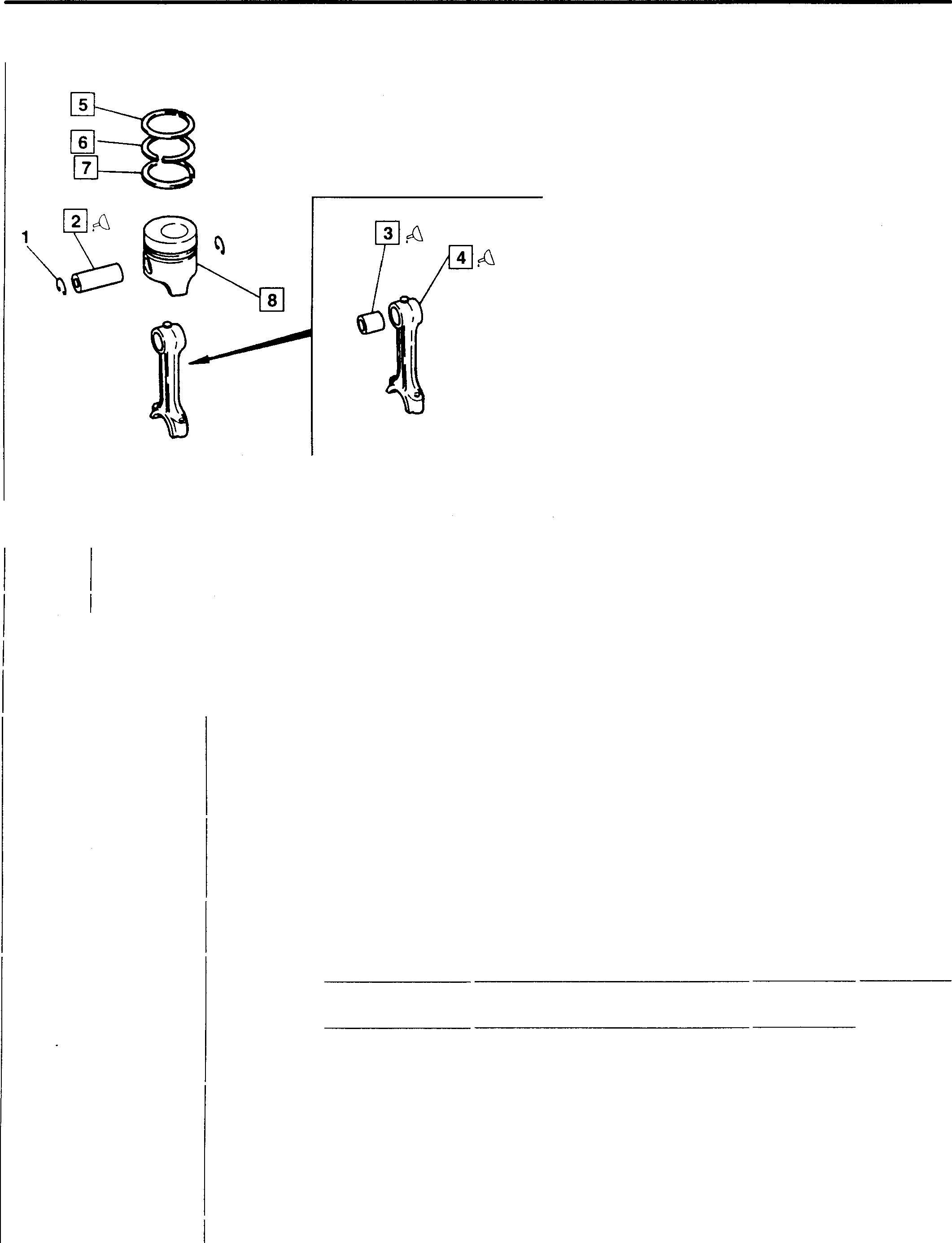
1 Snap ring
2 Pistonpin
3 Connecting rod bushing
4 Connecting rod
5 1stcompression ring
6 2nd compression ring
7 Oil ring
8 Piston
• Assembly sequence Reversetheorder of disassembly.
Servicestandards
Location Maintenanceitem
2,3 Pistonpin-to-connectingrodsmallend bushingclearnace
2,8 Pistonpin-to-pistonclearance
4 Connectingrodbendandtorsion
5 to 7 Pistonring 1stcompresendgap sionring
6D16-TLEA
2ndcompressionring
6D16-TLEA Oilring
6D16-TLEA
5 to8 Pistonring-to- 1stcomprespistonring sionring grooveclearance
2ndcompressionring Oilring
6D16-TLEA
6D16-TLEA
ll-36
02012
Standard value Limit (Basicdiameterin []) 0.1 [0.004to0.02 0.05 - 0.05 0.35to0.55 1.5 0.35to0.55 1.5 0.35to0.55 1.5 0.11to0.15 0.2 0.07to0.10 0.15 0.03to0.06 0.15 Unit: mm Remedy Replace Replace Corrector replace Replace Replace Replace Replace Replace Replace
38MM Pin 0.02-0.05 42MM Pin 0.02-0.05
� Oils
Location Points ofapplication
2 Pistonpin outer surface
3 Connecting rod bushing outersurface
4 Bushing installation surface ofconnectingrod
� Special tools
Location
Connecting RodBushing Puller Tool name and shape
Connecting Rod Bushing Puller Kit Piston Ring Tool
installing piston rings
Engineoil Engineoil Engineoil Part No. MH061778 Kinds 11 Quantity As required As required As required Application
1 --11 --; Removingand
rod
to 7
3
installing connecting
bushings 5
��015 <)>100 to<)>120 02013 30091-07100 Removingand
11-37
MH062023
Mitsubishi 6D16TLEA Tadano Crane
PISTONS, CONNECTING RODS, AND CYLINDER LINERS
♦ Service procedure [i)I]]
Piston and connecting rod
If the clearance exceeds the specifiedlimit, replace the defective part(s).
Connecting rod bushing - Straight bushing
[ Removal]
Applythe � Connecting Rod Bushing Puller to the connecting rod bushing 3 Using a press, apply pressure of approximately 49 kN (5,000 kgf) such that the bushing is pressed out of the connecting rod 4.
[Installation]
• Align oil hole A in the connecting rod bushing 3 with oil hole B in the connecting rod 4.
• Apply the � Connecting Rod Bushing Puller to the connecting rod bushing 3. Using a press, apply pressure of approximately 49 kN (5,000 kgf) such that the bushing is pressed into the connectingrod 4 from the chamfered side C.
NOTE
Afterinstallingtheconnecting rod bushing 3, insertthepistonpin 2 and check that it turns smoothly and without play.
02017 4 3
4
11-38
13616
13617
Replacetheconnectingrodbushing3usingthe(gConnectingRodBushing Puller Kit. Thisconsistsof thefollowing parts:
D:Base
E:Bracket
F: Puller
G: Collar
H: Plate
J:Collar
K:Nut
[RemovalTaperedpinbushing]
• Removethe bearing (if fitted) from the big end of the connecting rod 4.
• Mount the connecting rod4on the base D and lock itinpositionwith the bracket E and plate H.
• Position the puller F and collar G as shown in the illustration. Then, slowlyapplypressureofapproximately49kN(5,000kgf)untiltheconnecting rodbushing3ispressedout.
[InstallationTaperedpinbushing
• Applyengineoiltothesmallendoftheconnectingrod4andtotheouter surface oftheconnectingrod bushing 3.
• FitthecollarJoverthepuller F, positiontheconnectingrodbushing3 andcollarGasshownintheillustration, andlockthisarrangementtogether with the nut K.
• Align theoilholes L in thesmall end of the connecting rod bushing 3 and connecting rod 4. Then, use a press to slowly apply pressure of approximately49kN(5,000kgf)untilthebushingispressedintoplace.
• Afterpress-fittingtheconnectingrod bushing3, reamittoachievethe specifiednominalclearance between the bushingandpiston pin 2.
NOTE
Afterinstallingtheconnectingrod bushing 3,insertthepistonpin 2 and check that it turns smoothly and without play.
[I]W[!] Piston pin, connecting rod, and piston [Removal]
• Tap outthepiston pin2 usinga rodand hammer.
• If thepiston pin 2 is difficult to remove, heat the piston8 in hotwater or usinga pistonheater.
02019 02020
11
02022
11-39
PISTONS, CONNECTING RODS, AND CYLINDER LINERS
[Installation)
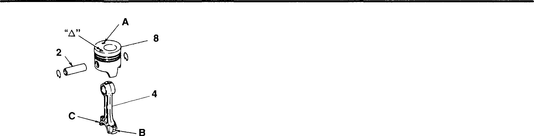
• Applyengine oil to the pistonpin 2. With the connecting rod 4and piston 8 aligned as illustrated, insert the piston pin to hold these components together.
• If the piston pin 2 is difficult to insert, heat the piston 4 in hot water or using a piston heater.
CAUTION_&-------------
• Nopistonshoulddifferfromanyotherpistonbyaweightofmore thanlog.
• Theconnectingrodsmustallhavethesameweightmark.
• Afterinsertingthepistonpin2,checkthatitturnssmoothlyand withoutplay.
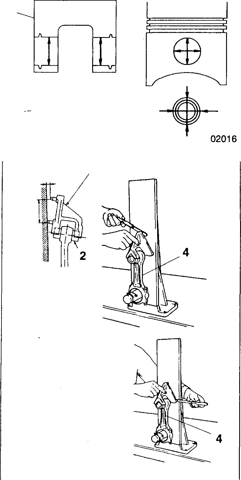
[I][!] Pistonpin-to-pistonclearance
Ifthe clearance exceeds the specified limit, replace the defectivepart(s).
2-q
[!] Connectingrodbendandtwist
• Fit the connecting rod bushing 3 and piston 2 in their respective positions of the connecting rod 4.
• Measure the extent of bending Aand twisting 8 in the connecting rod 4.
• Ifeithermeasurementexceedsthespecifiedlimit, replacetheconnecting rod 4 or rectify it.
C: Connecting rod 4 aligner (measurement device)
NOTE
• Before mounting the connecting rod 4 on the connecting rod aligner C, installtheupperandlowerconnectingrodbearingsin theirrespectivepositions.
• Measurementsmustbemadewiththeconnectingrodcapmountingnutstightenedtotheirspecifiedtorque.[DP.11-29
8
A C D 8 ,�r r-b�I 100mm �> -�t ;?. I - -- -� ;; 2 1/,, C 11-40 02023 02039 02040
Mitsubishi 6D16TLEA Tadano Crane
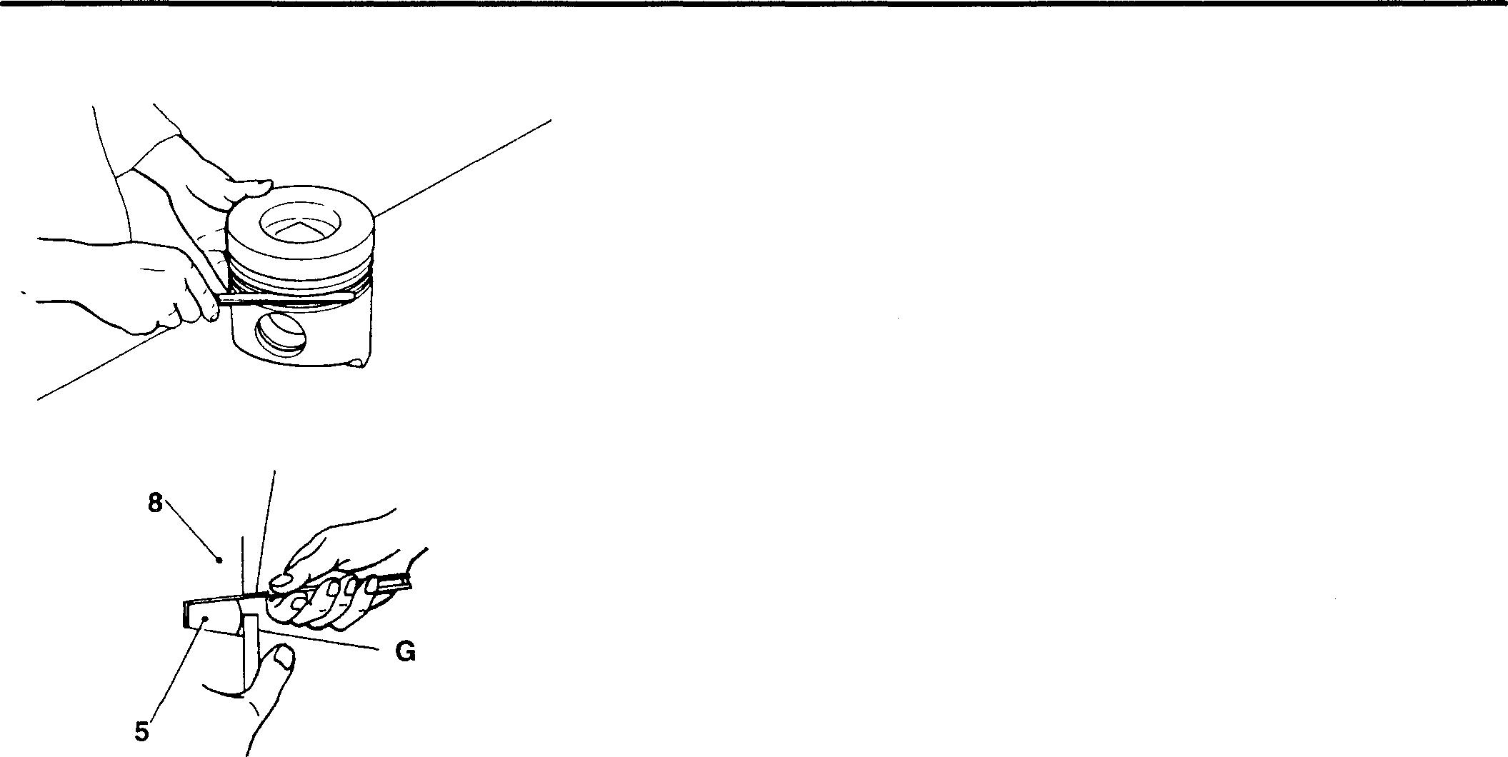
[fil to[]] Piston rings and piston Piston rings
[Removal]
[Installation]
• Fittheoil ring7ontothepiston8withitssiderail gaps Aandtheexpander spring gap B in the positions illustrated.
• Fitthecompressionrings5, 6ontothepistonsuchthatthemanufacturer's marks C near the gaps face upward.
• Align the compression ring gaps D, E as illustrated.
D: 1st compression ring gap
E: 2nd compression ring gap
.6.: Front mark
[Inspection]
(1) Piston ring end gap
• Usingthecrownofapiston8, pushthe piston ring 5, 6or 7horizontally into a cylinder liner F for measurement.
• Taking care not to move the piston ring 5, 6 or 7, measure the end gap. Replacealltheringsofapistonifanygapexceedsthespecified limit.
NOTE
• To keep the piston ring 5, 6 or 7 horizontal, be sure to insert them into the cylinder liner F using a piston 8.
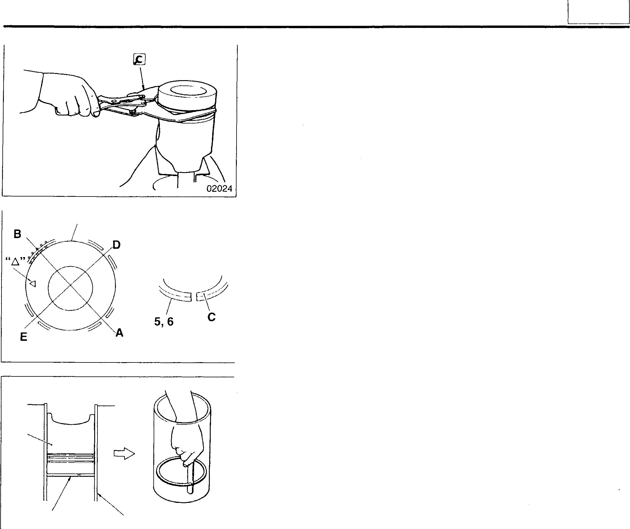
• Pushthepistonring5, 6or7downtothebottomofcylinder liner F; the bottom should be less worn than the top.
• Piston rings 5, 6 or 7must be replaced as a set. Never replace piston rings individually.
8 02028 8 0 5 to 7 F 02027
11
11-41
PISTONS, CONNECTING RODS, AND CYLINDER LINERS
(2) Piston ring-to-piston ringgroove clearance
• Ifanymeasurementexceedsthespecified limit, replace thedefective part(s).
• Measure the 1st compression ring 5 clearance with a thickness gauge H whilepressingtheringagainstthepiston 8witha straight edge G.
NOTE
• Removeanycarbondepositsfromtheringgrooveofthepiston 8andmeasuretheclearancearoundthepiston'sentireperiphery.
• Pistonrings5,6,7mustbereplacedasaset.Neverreplacepiston ringsindividually.
H 02025 02026 I1-42
11 MEMO 11-43
FLYWHEEL PTO
16919

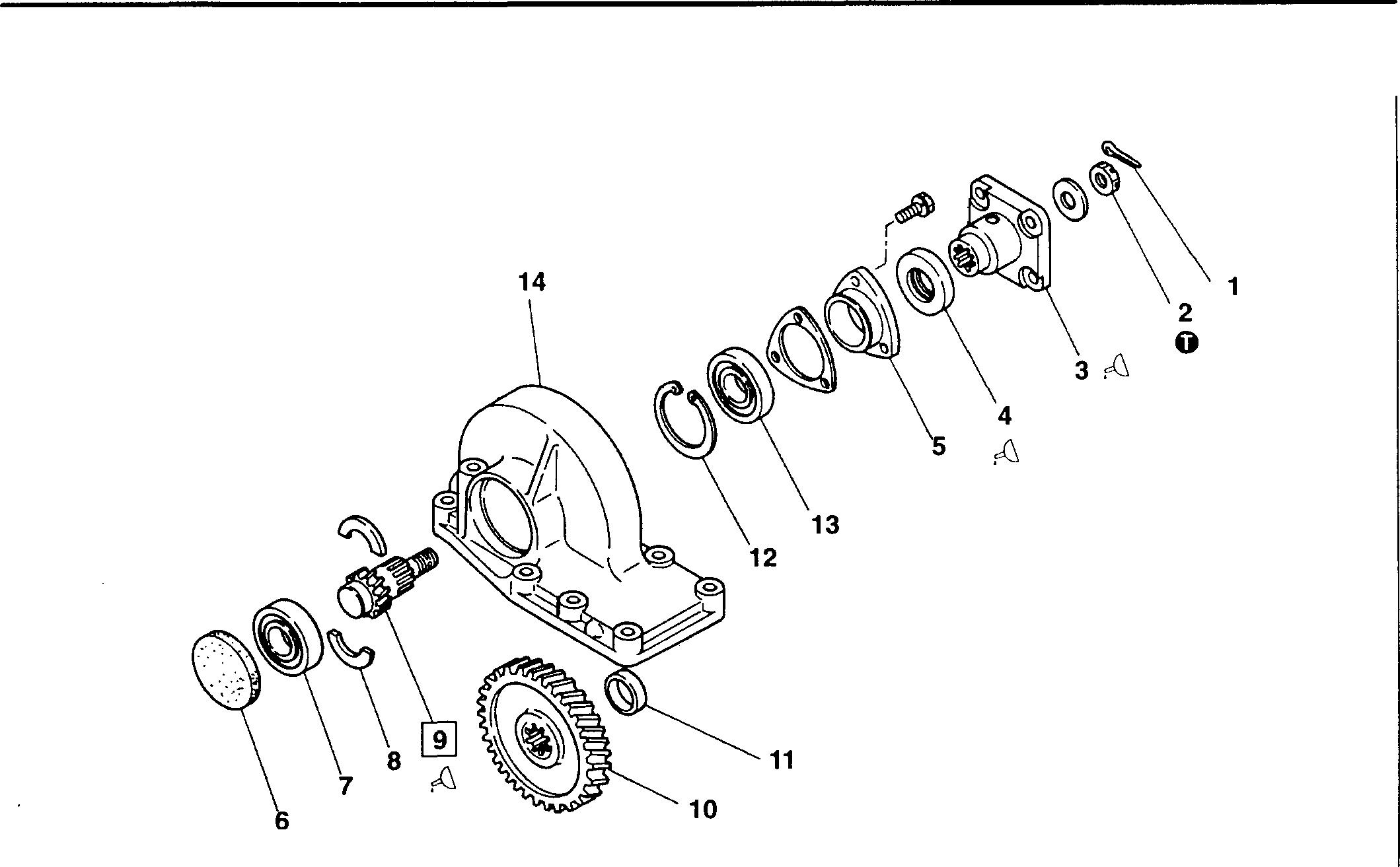
• Pre-disassembly inspection P.11-49
• Disassembly sequence
1 Flywheel PTO head assembly Q] P.11-46
Shim
Seal cap
PTO idler shaft
PTO idler gear A
• Assembly sequence
Reverse the order of disassembly.
Spacer
PTO idler gear
Spacer
Snap ring
Ball bearing
Snap ring
A: Locating pin
*: Flywheel housing Q] P.11-48
2
3
4
5
6 Ball bearing 7 Cotter 8
9
Nut
Cover
11-44 10
11
B 12
13
14
15
Service standards
Location
Maintenance item
- Gear back- Between PTO idlergear lash Aand No.1 idlergear
Between PTOgearand idlergearB
Total PTOgear backlash
to0.26
0 Tightening torques
Location
Parts to be tightened
4 PTO idlershaft mounting nut
02045
to0.35 Tightening
125{12.8}
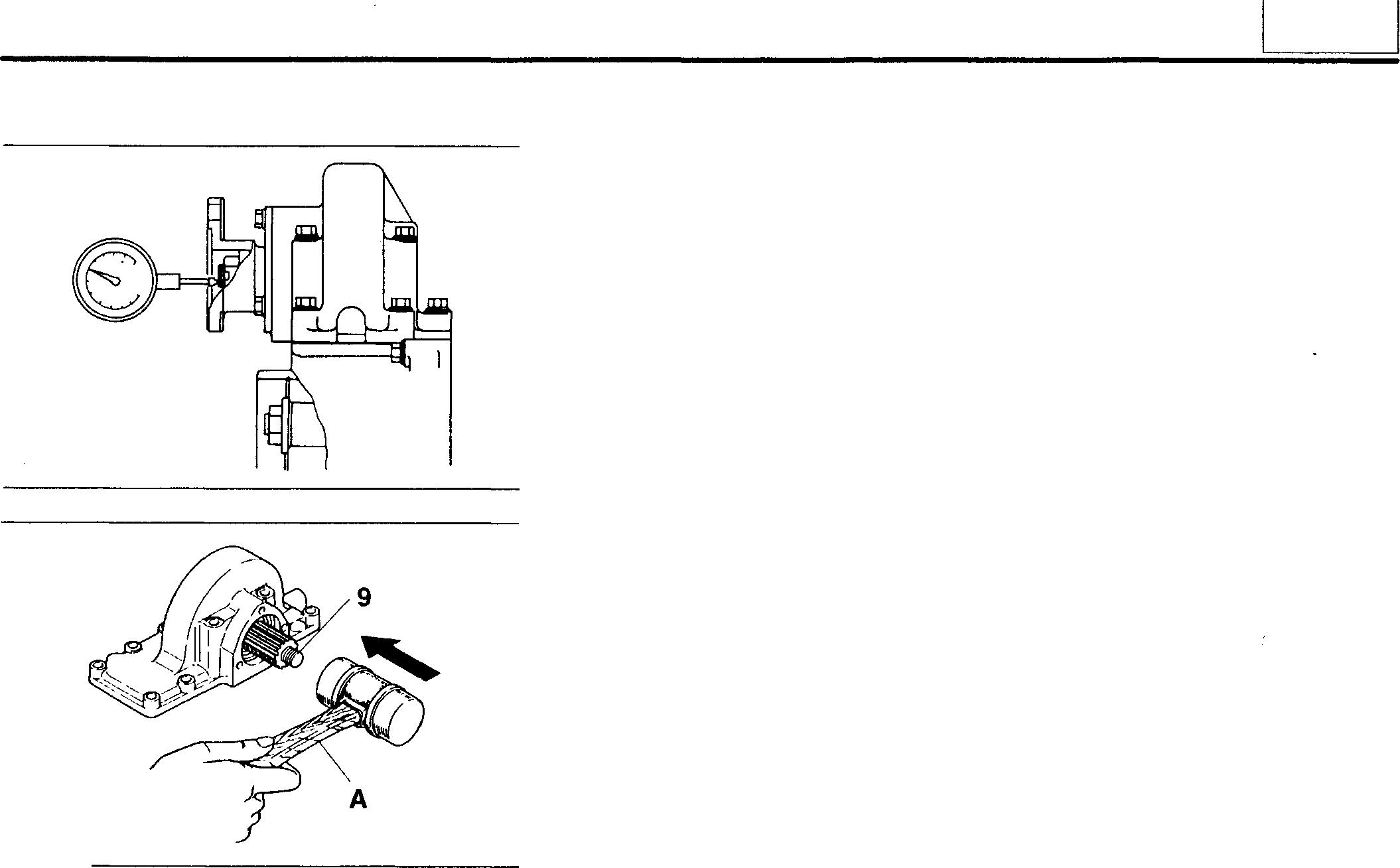
♦ Service procedure
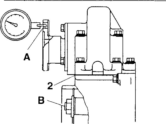
•Pre-disassembly
• MeasurementofthebacklashbetweenPTOidlergearAandNo.1idler gearandofthetotalbacklashshouldbe carriedout at the qi100 pitch circle onthe PTOflangeA. Ifbacklash is outofspecification, adjust it using a shim 2.
Shims are available in the followingsizes: 0.1 mm, 0.2 mm, and 0.3 mm.
• Measurement of the backlash between the PTO gear and PTO idler gearBshouldbecarriedoutattheqi100pitchcircleonthePTOflange. Hold the PTO idler shaft 8 steady while taking measurements. If the backlashisout of specification, adjust it using a shim 2.
Shimsareavailable in the following sizes: 0.1 mm, 0.2 mm, and 0.3 mm.
Standardvalue 6D16TLEA 0.12
6D16TLEA 0.12
0.18
torque
to0.26
Gear backlash 11 Unit: mm Limit Remedy Reference 0.35 value Reference 0.35 value - Rectify or replace Unit: N·m {kgf·m} Remarks -
inspection
11-45
FLYWHEEL PTO
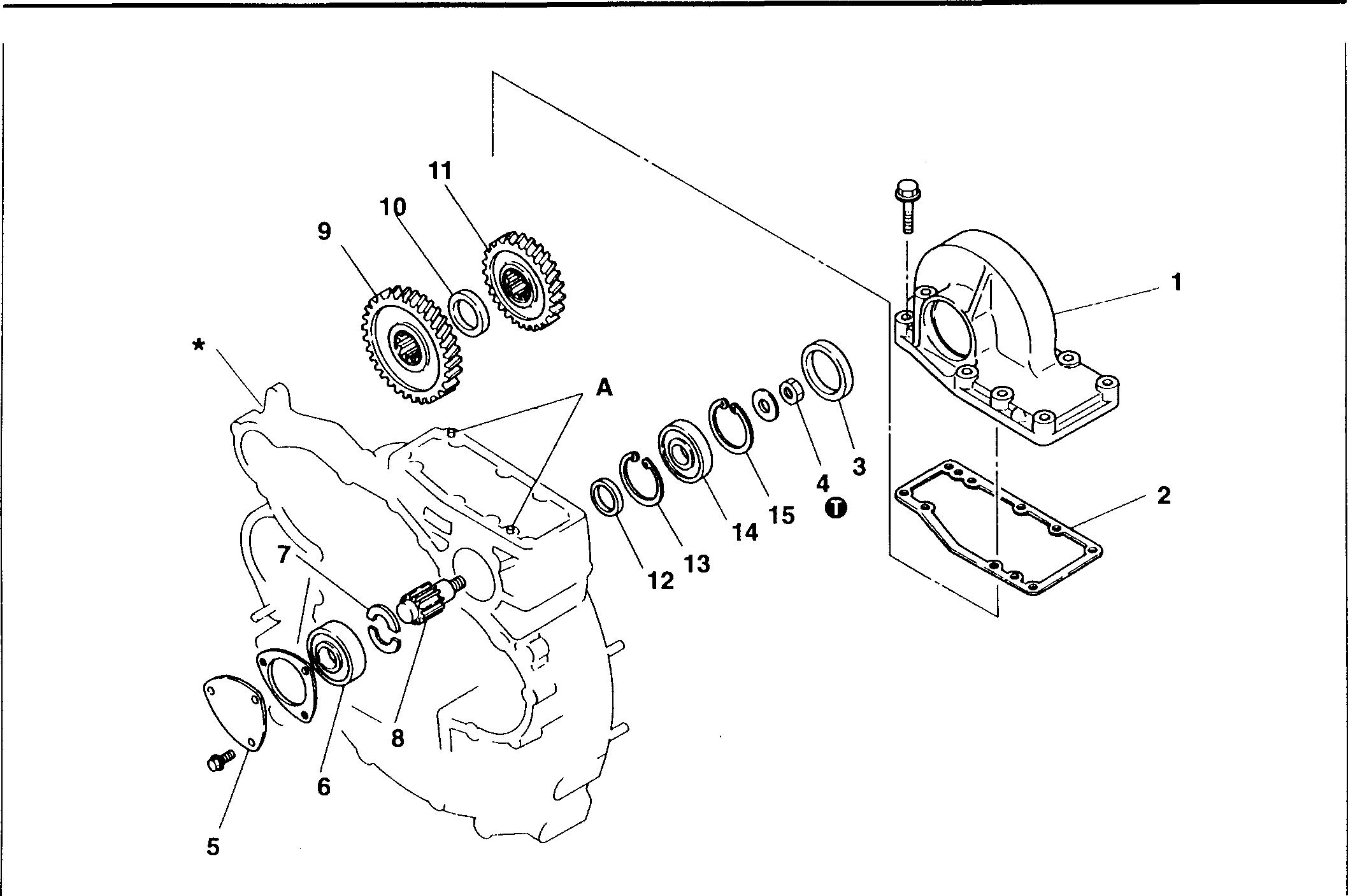
Flywheel PTO Head Assembly
• Disassembly sequence
1 Splitpin 2 Nut
Flange
Oil seal 5 Rearcover
• Assembly sequence
Opposite of disassembly sequence.
Service standards
Location Maintenanceitem - PTO shaft end play
0
Tightening torques
Location Parts tobetightened
2 Flange mountingnut
� Oils
Sealcap
Ballbearing
Cotter
PTOshaft
PTOgear
Location Pointsofapplication
3 Flangesplines
4 Oil seal lip 9 PTO shaft splines
(12.8}
Wheel bearinggrease [NLGI N0.2 (Li soap)] Asrequired
Wheel bearinggrease [NLGI N0.2 (Li soap)) Asrequired
Wheel bearing grease [NLGI N0.2 (Li soap)] As required
3
4
7
8
9
10
6
11-46 Standardvalue Oto0.8 11 Spacer 12 Snapring 13 Ballbearing 14 Cover Limit16921 Unit: mm Remedy Replace Unit: N·m {kgf·m} Tightening
Remarks 125
-
Quantity
torque
Kinds
♦ Service procedure
• Pre-disassembly inspection
PTO shaft end play
If the measurement exceeds the specified limit, replace the defective part(s).
11] Removing PTO shaft A: Plasticmallet
13618 16922
11
11-47
FLYWHEEL
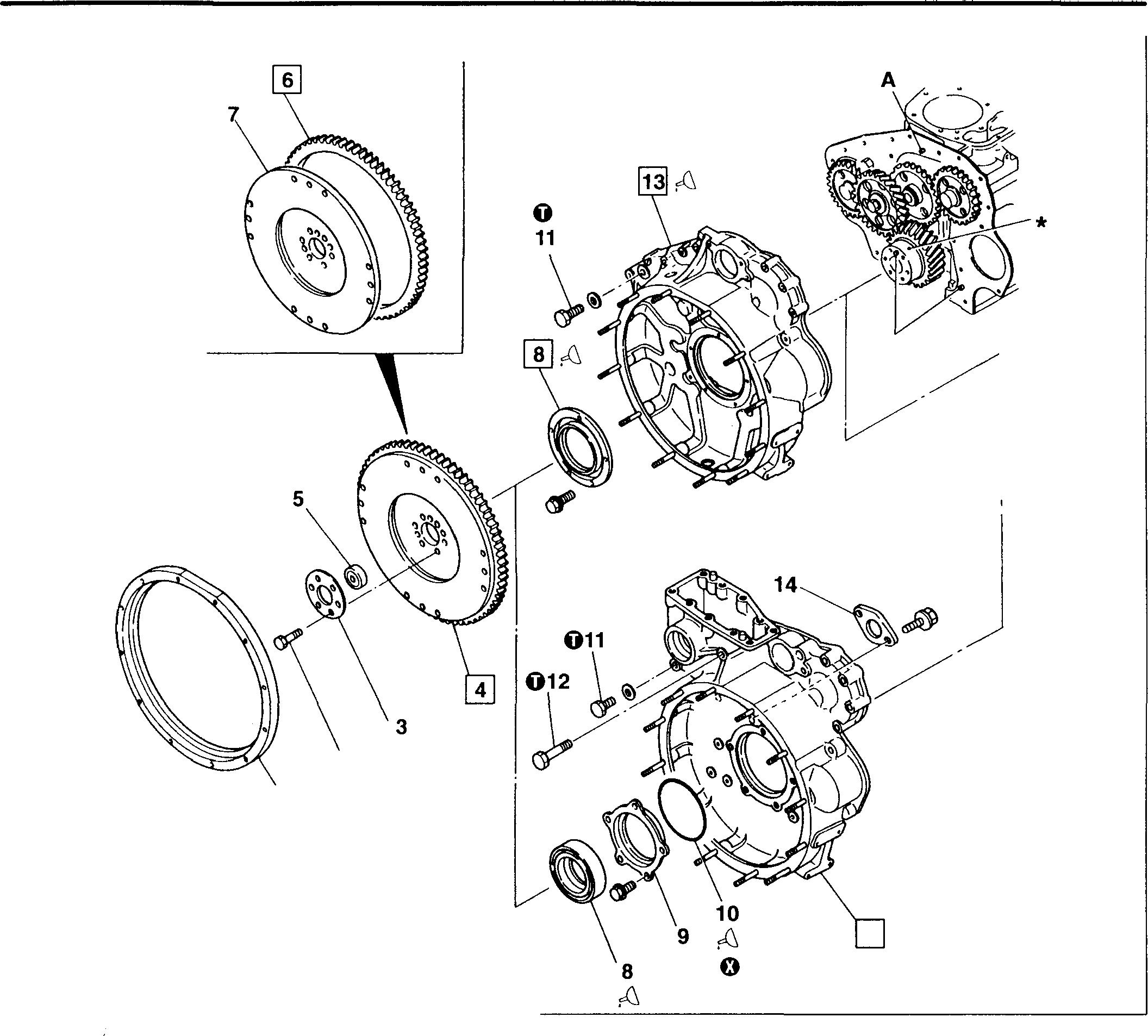
• Disassembly sequence
Spacer
Bolt
Washer plate
Flywheel
Pilot bearing
Ringgear
Rear oil seal
Rear oil seal retainer <models with flywheel PTO>
• Assembly sequence
Reverse the order of disassembly.
<Without flywheel
O-ring <modelswith flywheel PTO>
<models withflywheel PTO>
Thrustplate <models withflywheel PTO>
*: Crankshaft [D P.11-72
Locatingpin
:Non-reusable part 16923
1
2
3
4
assembly 5
6
7
8
2 1 0 Ii 9
F_lywheel
11-48
PTO> A
flywheel PTO> 13 :fi 10
11
12
13 Flywheel housing 14
<With
Plug
Bolt
A:
0
0 Tightening torques
� Oils and sealants
� Special tools
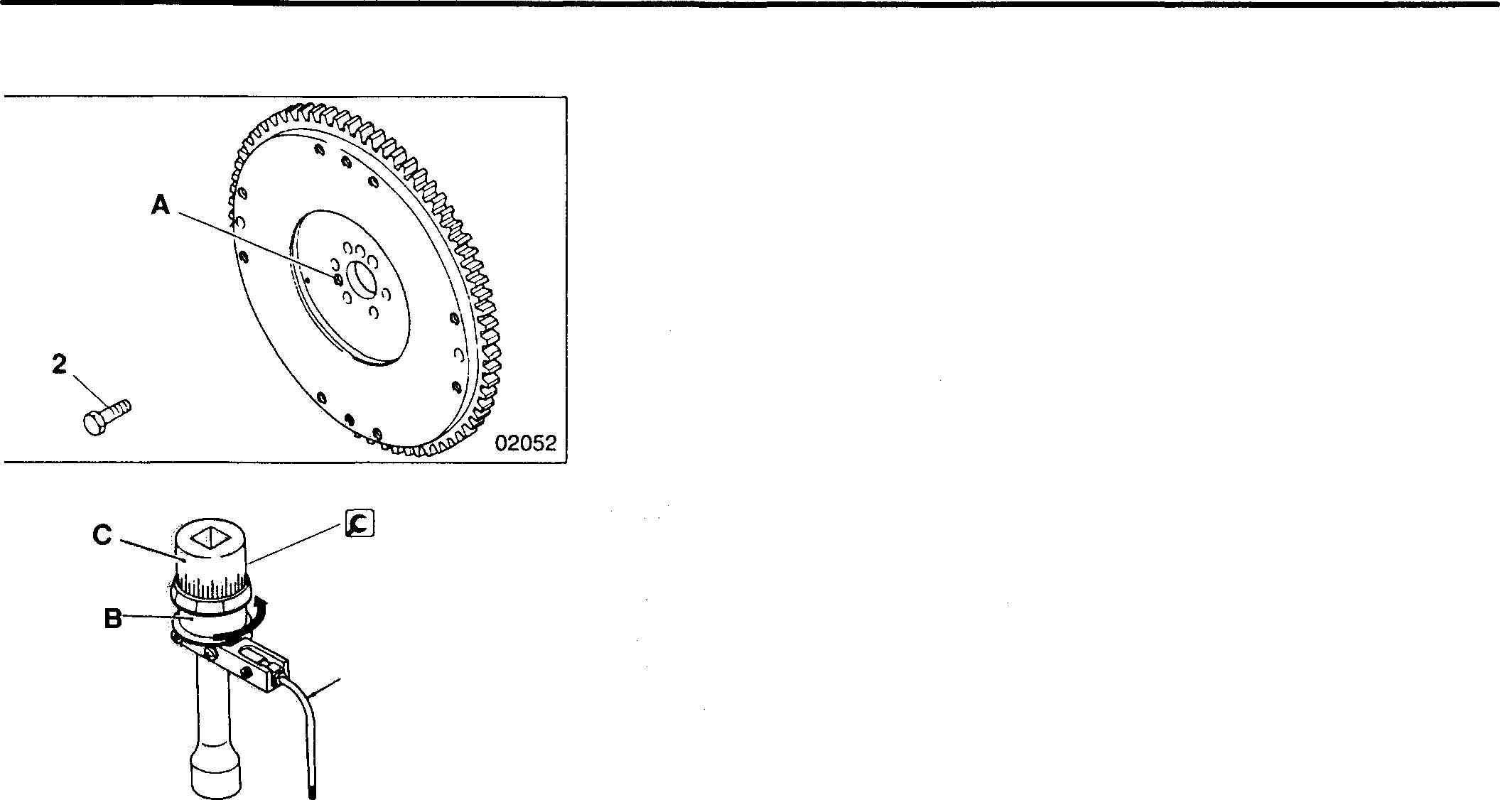
11 Service standards Unit: mm Location Maintenance item Standardvalue Limit Remedy 4 Flywheel Friction surfacedistortion 0.05orless 0.2 Correct or assembly replace Heightof frictionsurface 20 19 Replace Friction surface runout (when - 0.2 Corrector fitted) replace 13 Eccentricity ofjoint - 0.2 Inspect or replace
Unit: N·m {kgf·m} Location Partsto betightened Tightening torque Remarks 2 Flywheelmounting bolt 98(10} + 150° • Wet • Can be reused upto 3times 11 Plug 88{9}12 Bolt <modelswithflywheel PTO> 34 (3.5} -
Location Pointsof application Kinds Quantity 2 Boltthreads Engineoil As required 8 Rearoil seal lip Engineoil As required Flywheel mounting surface ofrear oilseal <models without Threebond 1207C As required flywheel PTO> 10 O-ring Engineoil Asrequired 13 Engine mounting surfaceof flywheelhousing Threebond1207C As required
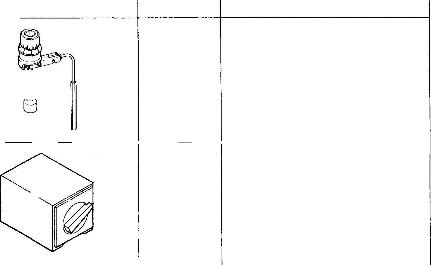
Location Tool name and shape Part No. Application SocketWrench MH062354 01984 4 >-- ---- -- >---- -------1 Fitting flywheel Magnetic Base MH062356 00471 11-49
t♦ Service procedure G) Flywheel assembly
[Removal]
Toremove the flywheel assembly 4, screw the mounting bolts 2 intothe removalholes A.
[Installation]
• The bolts 2 can be used only three times. Before refitting the bolts, makeapunchmarkontheheadofeachonetoindicatetimesofreuse.
CAUTION,&-------------
lt any bolt already has three punch marks, it must not be reused any more; replace it with a new one.
• Tightenthebolts 2 totheirspecifiedtorque, then tightenthemfurther inaccordancewith the following procedure:
• Turnthe holder B of the lg SocketWrench counter-clockwise totension thebuilt-inspring.
C:Socket D:Rod E:Rod (extension)
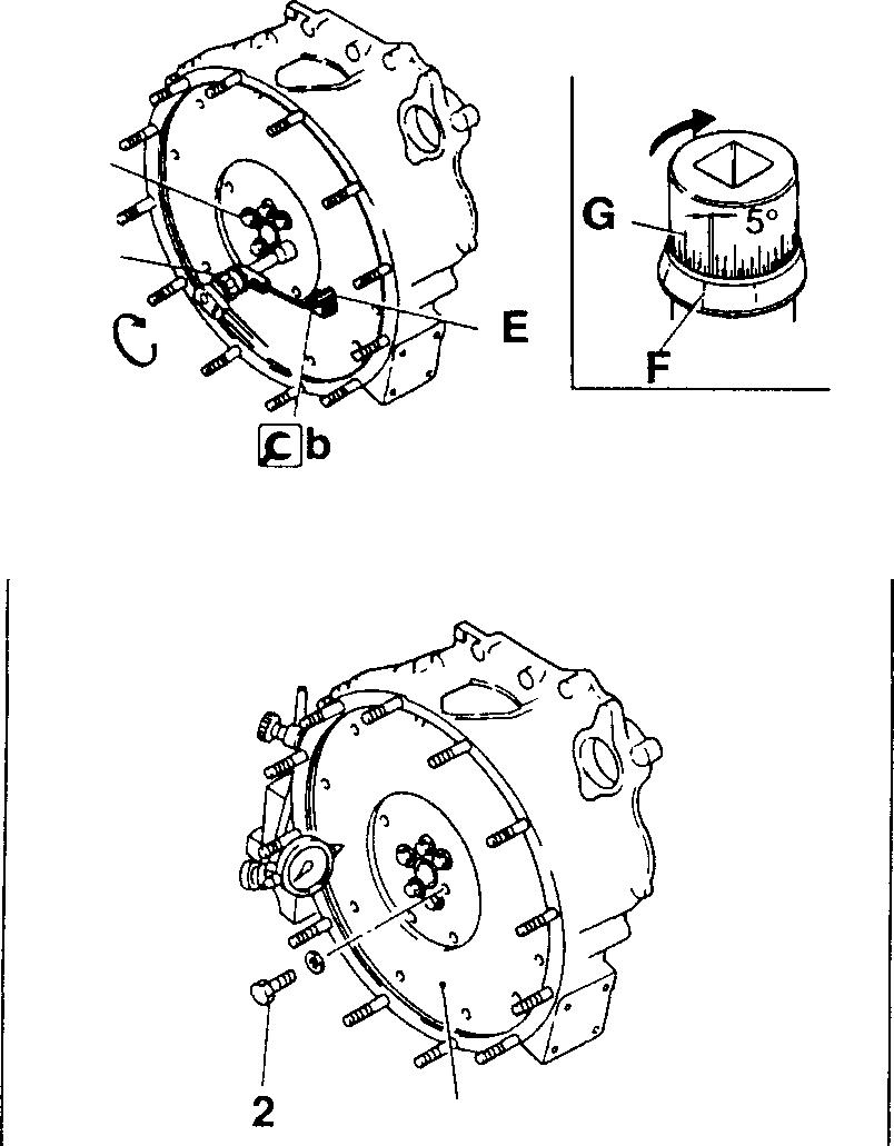
• Set the socket wrench such that the built-in spring forces.the rod E againstthe [gb Magnetic Base.
• On theholder 8, selectthe inscribed line Fthatiseasiestto see.
• Usingtheselectedlineasareference,turnthesocket150° dlockwise. (One gradationon thescale G represents5°.)
CAUTION,&------------
Sincethe bolts2 utilize theplasticregiontighteningmethod, they must not be tightened further after this procedure.
[Inspection]
(1) Runout
• Tightenthe bolts 2 totheirspecifiedtorque.
• Ifrunoutexceedsthespecifiedlimit, checkthatthebolts 2 aretightenedcorrectlyandinspectthecrankshaft*mountingsurface.Then, rectifyorreplace the flywheel assembly 4 as required.
FLYWHEEL 3 [ga 11-50 4 D
E � 01991 14312 02055

�ritj:,,.


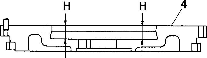
(2) Height offriction surface
Ifthemeasurementisbelowthespecifiedvalue, rectifyorreplacethe flywheelassembly 4.
H: Height offriction surface
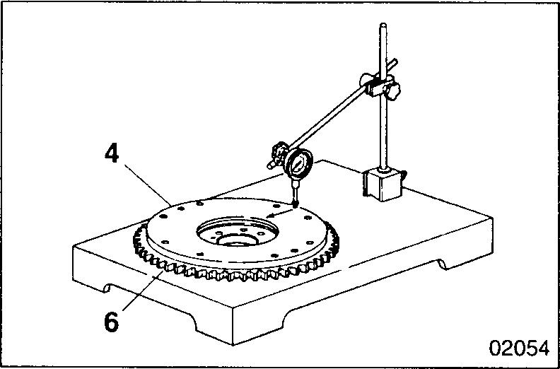
(3) Distortion offrictionsurface
If distortionexceeds thespecifiedlimit, rectify or replace the flywheel assembly4.
NOTE
Ifanyabnormalityisevidentontheringgear6,replacethering gear beforemakinginspections.
[Rectification]
Grindthefrictionsurfacesuchthatitsheight Hremainsgreaterthanthe specifiedminimum.Thefrictionsurfacemustremainparallelwithsurface J with atolerance of 0.1 mm.
[]] Ringgear
[Inspection]
Inspecttheringgear6fordamageandabnormalwear.Ifanydefectisevident, theringgearmustbereplaced.
[Removal]
• Heattheringgear 6 evenlywithanacetylene torch orthe like.
CAUTION&_--------------
Be carefulnottoget burned.
• Removetheringgear6fromtheflywheel7bytappingarounditsentire periphery.
H H 03349
03351 7 6
11
)$1/2 l
02057
11-51
4>2 mm
I[Installation]
• Usingapistonheaterorthelike,heattheringgear6toapproximately 100°c for 3 minutes.
CAUTIONLD,-------------
Be careful not to get burned.
• Fittheringgear 6 with the non-chamferedsideof its teeth towardthe flywheel 7.
A: Chamferedsideof ringgear
[fil Fitting rear oil seal <Models without flywheel PTO>
• Applyaneven,unbrokenbeadofsealant A totherearoilseal 8 inthe positionillustrated B.
• Fittherearoilseal 9 ontotheflywheelhousing 12 within3minutesof applying thesealant A.
CAUTIONLD,-------------
• Ensure that the sealant application position B on the oil seal 8 is clean before applying sealant.
• Whenfitting the rear oilseal 8, holdit firmlyinposition toprevent spreading the sealant.
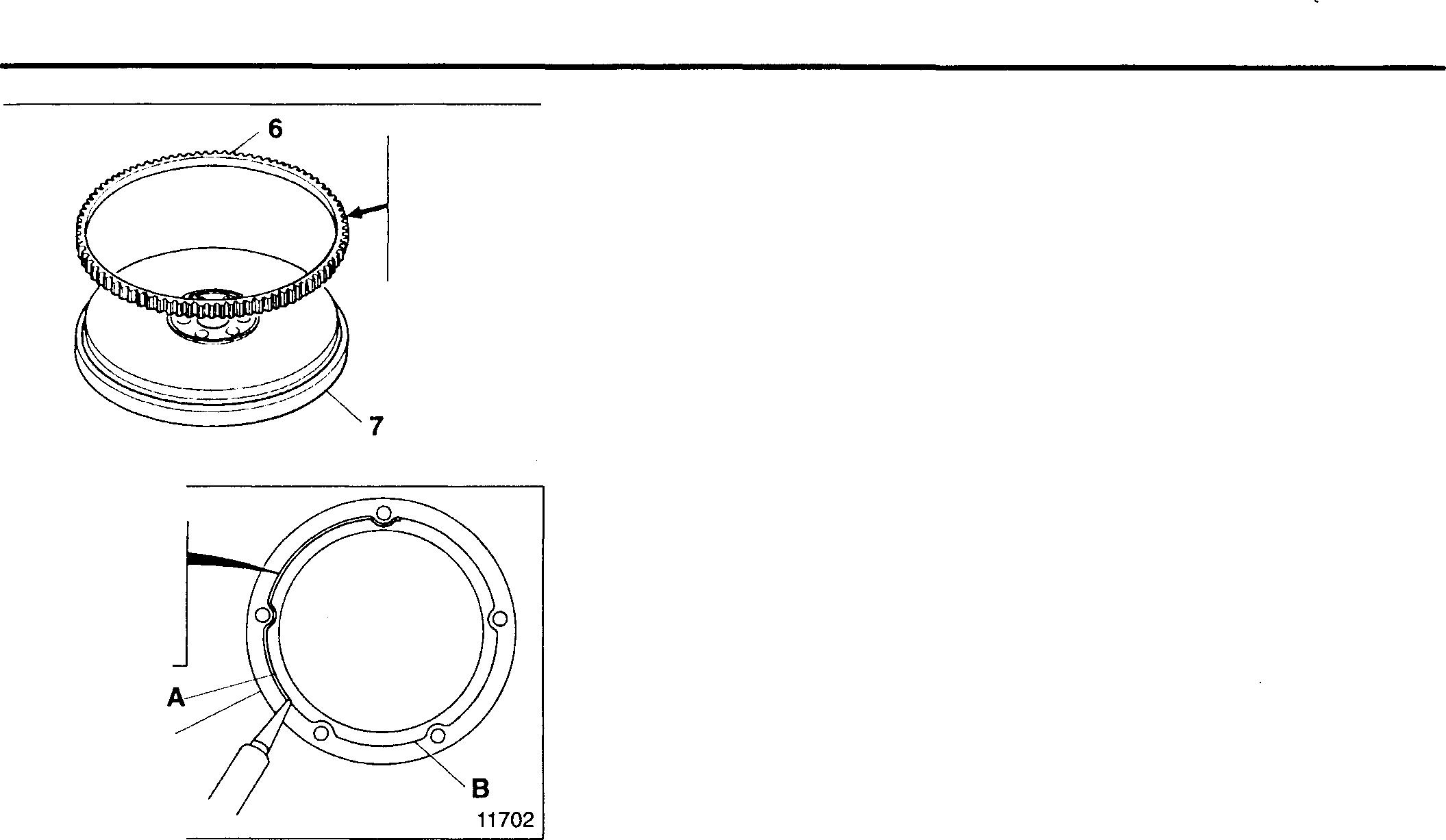
• Afterfitting therearoilseal8,waitatleast30minutes beforestarting the engine.
• Applyanew beadofsealantAwheneverthe mounting boltsofthe rear oil seal 8 have been loosened.
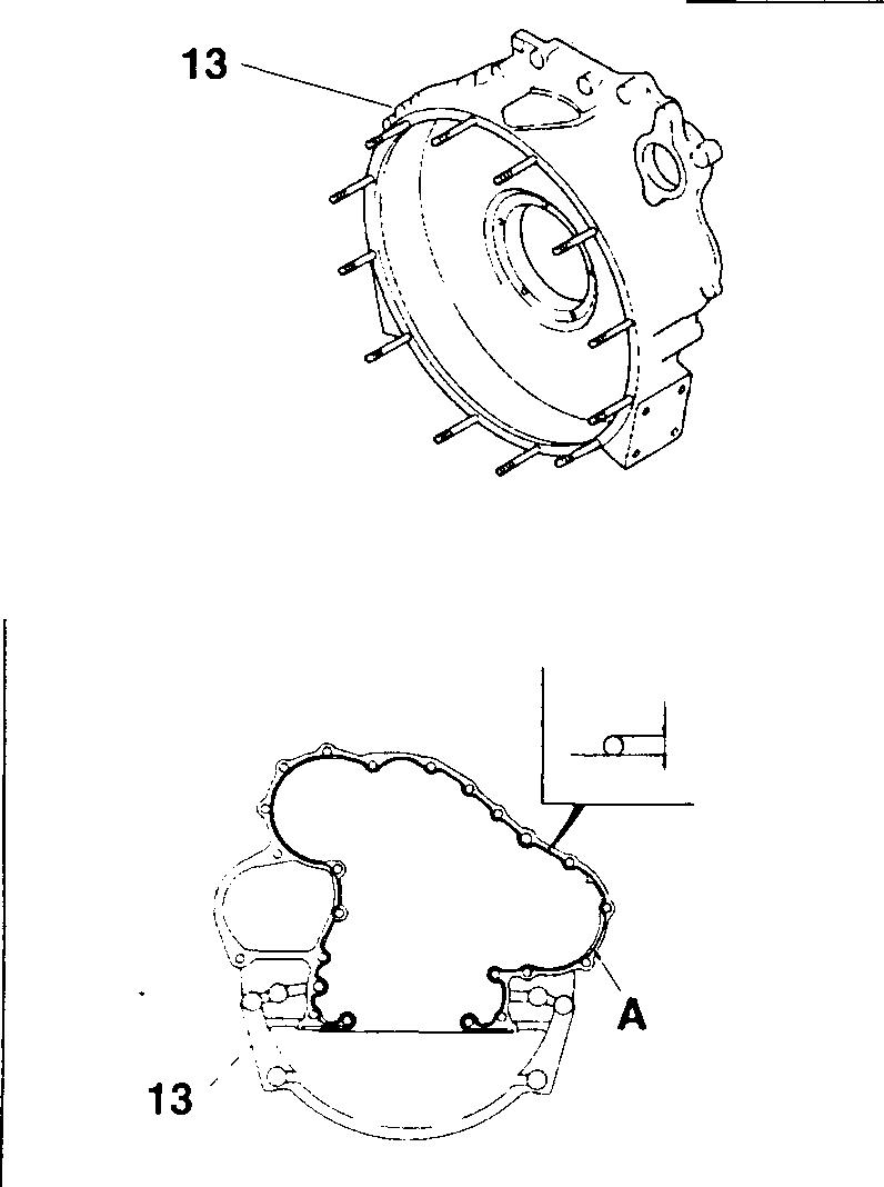
4>2 mm
• Applyengineoil to thelipoftherearoil seal 8.
• Fittherearoilseal 8 ontotheflywheelhousing 13inthedirectionillustrated.
� Flywheel housing
[Installation]
• Applyaneven,unbrokenbeadofsealantA tothecrankcasemounting surface oftheflywheelhousing 13.
• Fittheflywheelhousing 13 ontothecrankcasewithin3minutesofapplying thesealant A.
CAUTION&-------------
• Ensurethatthesealantapplicationpositionontheflywheelhousing 13 is clean before applying sealant.
• When fitting the flywheel housing 13, hold it firmly in position to prevent spreading the sealant.
• After fitting the flywheel housing 13, wait at least an hour before starting the engine.
• Apply a new bead of sealant A whenever the mountiing bolts of the flywheel housing 13 have been loosened.
FLYWHEEL A
A �
8 "UP"8� �<
11-52
03353 02059
11704
[Inspection]
• Rotate the crankshaft and check the extent of eccentricity at the joint A of the flywheel housing 13.
• If eccentricity exceeds the specified limit, carry out reassembly.
• If eccentricity stillexceeds thespecified limit after reassembly, replace the defective part(s).
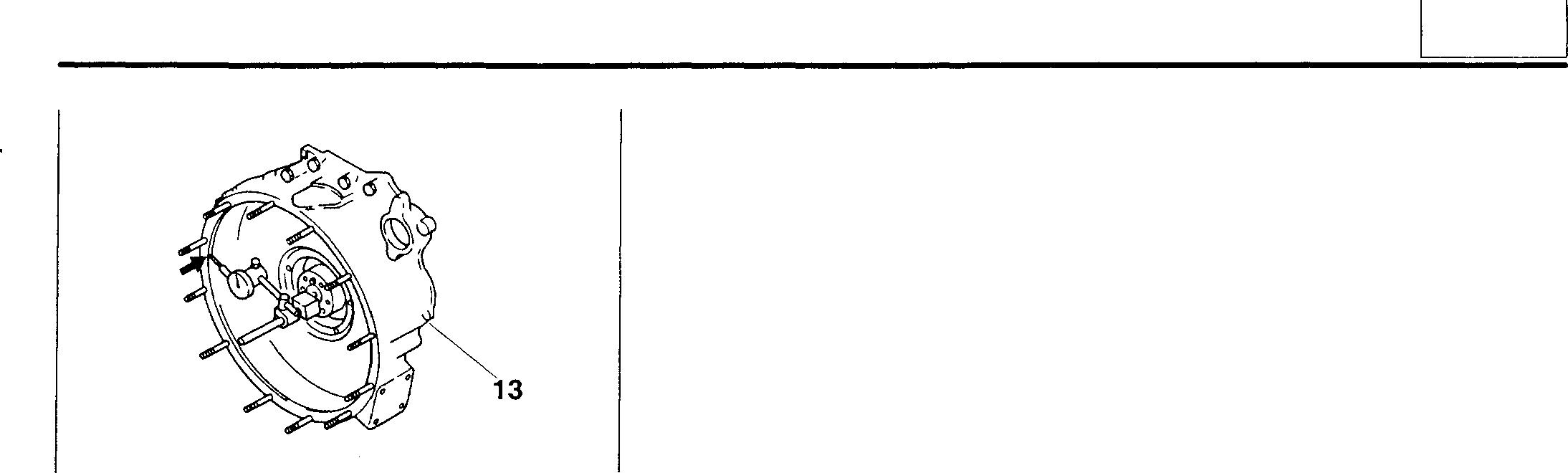
A
11
02062
11-53
TIMING GEARS
*2
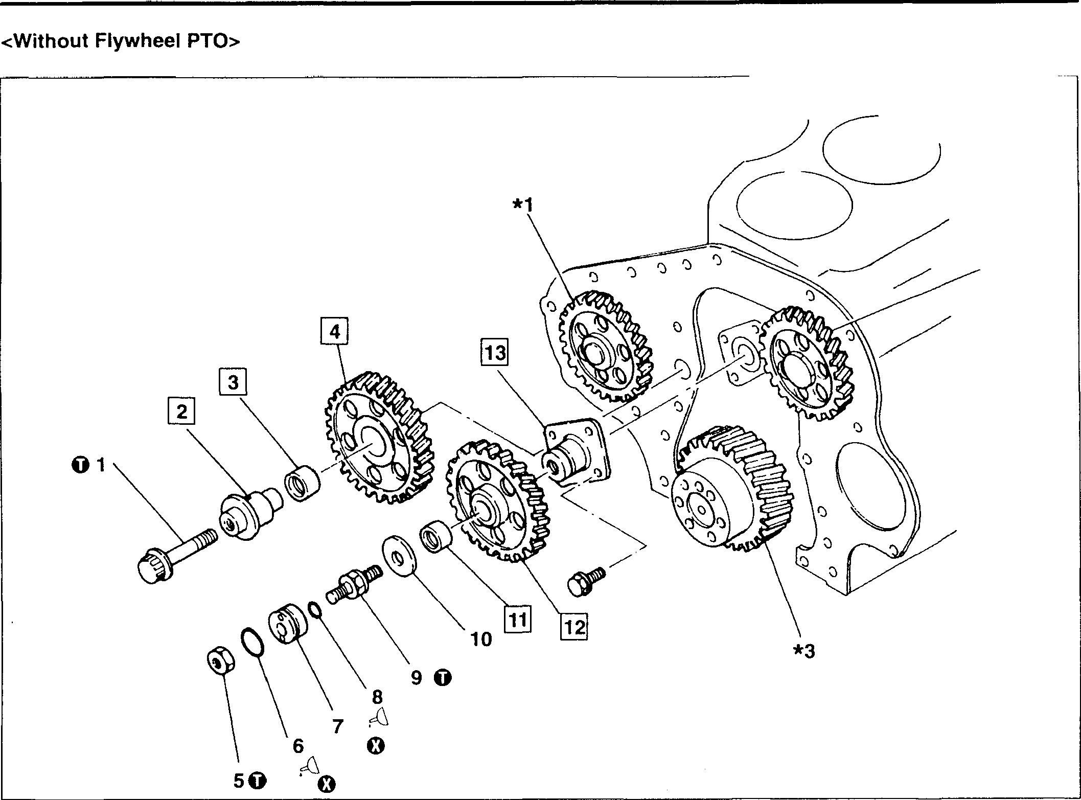
• Pre-d"isassembl . OJ P.11-S6 Y inspection
• Disassembl
1 Y sequence Bolt
! No. 1 idler shaft No. 1 idler
4 No. 1 idl gear bushing
5 Nut er gear
6 O-ring 7 Collar
8 O-ring 9 Bolt
• Assembl R y sequence
everse th
e order of disassembly.
10 Thrust wash
11 No. 2 idler er
12 No. 2 "di gear bushing
13 N ' er gear o. 2 idler shaft
*1: Drive gear
*2: Camshaft
*3: Cranksh iear CO P.11-64 a gear CO P.11-72
16939
0: Non-reusable part
CA�TIONLfs
Sincethe N ----o. 1Idlerg ported by the No ear4issupthese part · 1 idlershaft 2 . s must b a single unit. e removed as

11-54
� Oils
11 Servicestandards Unit:mm Location Maintenanceitem Standardvalue Limit Remedy (Basicdiameterin[]) - Gear BetweenNo.1idlergearandcrank- 0.08to0.15 0.35 Replace backlash shaftgear BetweenNo.1idlergearandNo.2 0.07to0.15 0.35 Replace idlergear BetweenNo.1idlergearanddrive 0.07to0.15 0.35 Replace gear BetweenNo.2idlergearandcamshaft 0.08to0.16 0.35 Replace gear 2,3 No.1idlershaft-to-gearbushingclearance [37)0.01to0.05 0.2 Replace 4,12 Idlergearendplay 0.05to0.15 0.3 Replace 11,13 No.2idlergearbushing-to-shaftclearance [32]0.01to0.05 0.2 Replace 0 Tightening torques Unit:N·m{kgf·m} Location Partstobetightened Tighteningtorque Remarks 1 No.1idlergearmountingbolt 88{9}5 Collarmountingnut 82{8.4}9 No.2idlergearmountingbolt 95{9.7) -
Location Pointsofapplication Kinds Quantity I 6,8 O-ring Engineoil AsrequiredI 11-55
Mitsubishi 6D16TLEA Tadano Crane
TIMINGGEARS
� Special tools Unit: mm
Location
2, 4 Gear Puller
Tool name and shape
Idler Gear Bushing Puller
� A B No. 1 idler
3, 11 gear bush- <I> 37 <!>40 ing No. 2 idler gear bush- <)>32 <I> 35 ing
Part No. Application
MH061326
02065
Removing No. 1 idler shaft and gear
<NO. 1> MH062601
<No.2> MH061779
02066
Removing and fitting idler gear bushings
13 Idler Shaft Puller
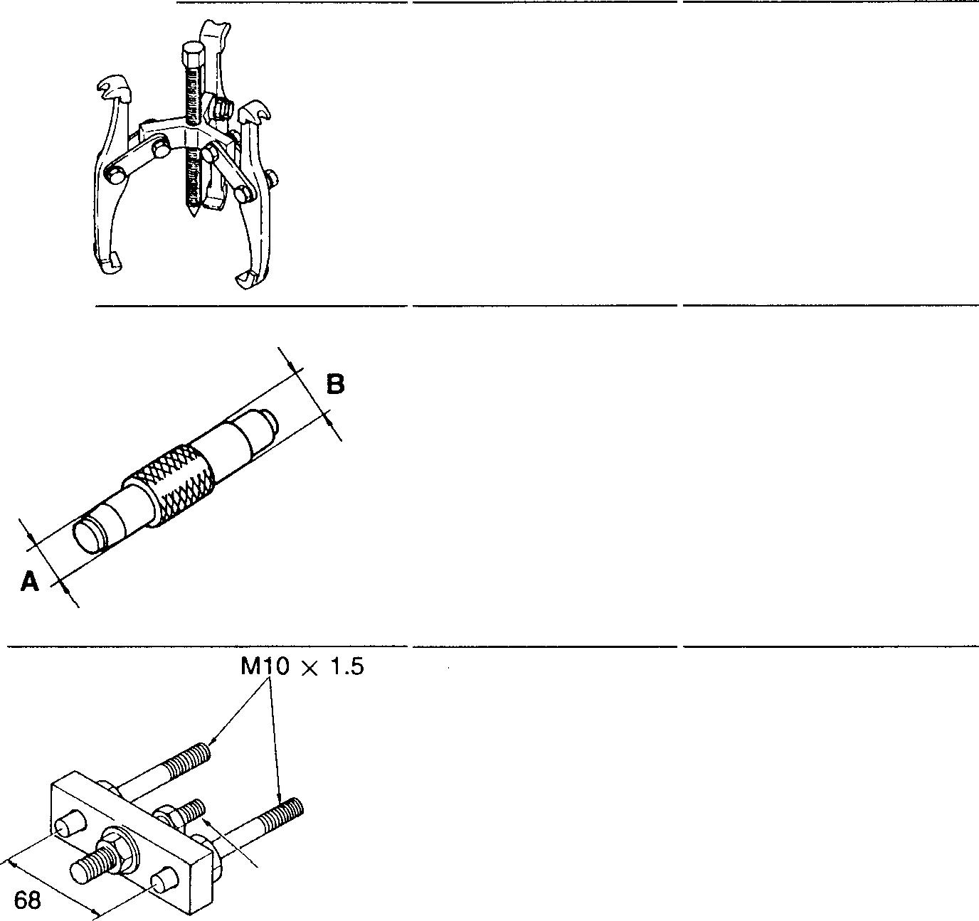
M8 X 1.5 02067
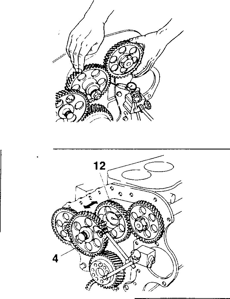
MH062405
Removing No. 2 idler gear shaft
♦ Service procedure
• Pre-disassembly inspection
(1) Gear backlash
For each gear pair, measure backlashat three or more points. If any measurement exceeds the specified limit, replace the defective part(s).
(2) Idler gear end play
Ifthemeasurementexceedsthespecifiedvalue, replacethedefective part(s).
11-56
02284
02069
[I] @] No. 1 idler shaft and No. 1 idler gear bushing
[Inspection]
Iftheclearanceexceedsthespecifiedlimit, replace the defectivepart(s}.
No. 1 idler gear bushing
[Removal]
A: Press
[Installation]
• Usingthe[&]IdlerGearBushingPuller,presstheNo. 1idlergearbushing3intotheNo. 1idlergear4fromthesideofthegearwhoseinternal diameteris chamfered B.
A: Press
• Afterinstallation,measuretheclearanceagain. Ifthemeasurementis below thenominal value range, ream the bushing 3.
[I] [iJ Removing No. 1 idler shaft and No. 1 idler gear
Loosen the bolt 1 byapproximately 15 mm, thenremove the No. 1 idler shaft 2 and No. 1 idler gear 4 as asingleunit.
[iJ [gj Installing No. 1 and No. 2 idler gears
Fitthe No. 1 and No. 2 idlergears 4, 12 such that theiralignment marks ("1","2","3","4")arealignedwiththoseonthegearswithwhichtheymate.
*1: Drive gear
*2:Camshaft gear
*3:Crankshaft gear
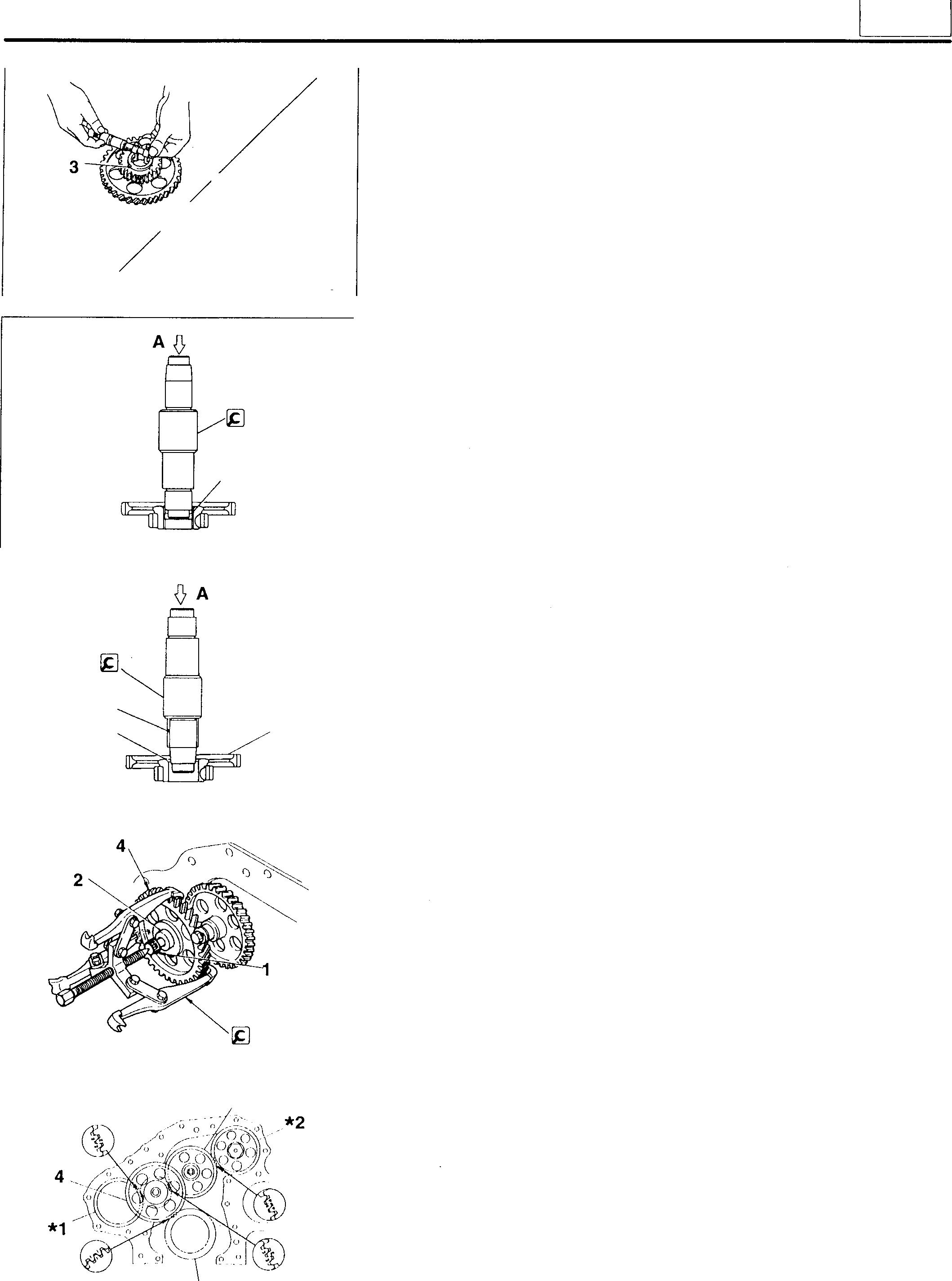
E8 3
♦ �02576 *3 3 12 I 4 02577 02578 02070 02074
B
11
ll-57
◊ A
ffi] � No. 2 idlergear bushing and No. 2 idlershaft
[Inspection]
Iftheclearanceexceedsthespecifiedlimit,replacethedefectivepart(s).
No. 2 idlergear bushing [Removal]
A: Press
[Installation]
• UsingthelgIdlerGearBushingPuller,presstheNo.2idlergearbushing11 intotheNo.2idlergear12fromthesideofthegearwhoseinternaldiameter is chamfered B.
A: Press
• Afterinstallation, measuretheclearanceagain. Ifthemeasurementis belowthe nominalvalue range, ream the bushing 11.
� Removing No. 2 idlershaft
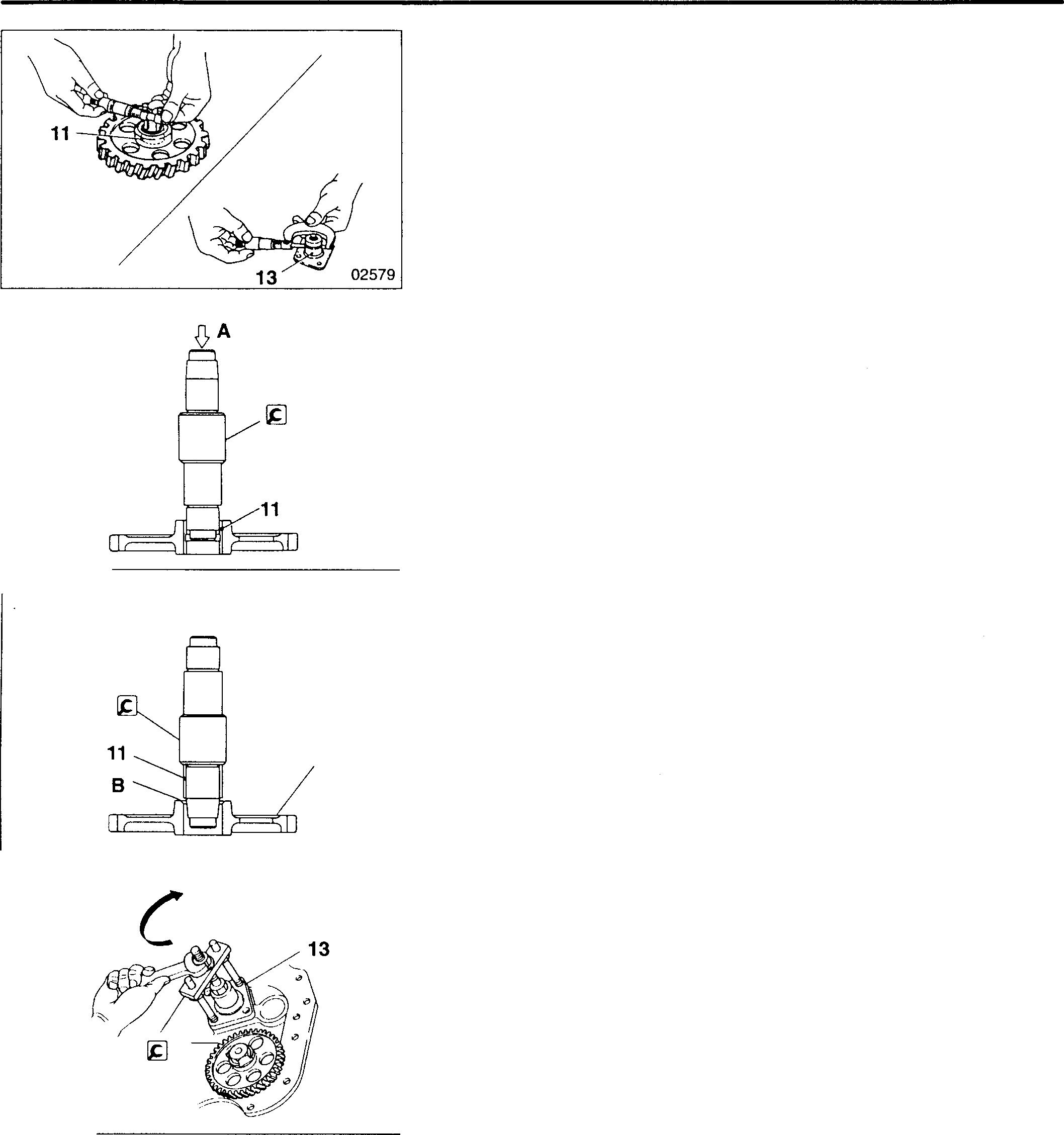
TIMINGGEARS 02580
12 02581 02075 ll-58
11
11-59
MEMO
TIMINGGEARS
<With Flywheel PTO>
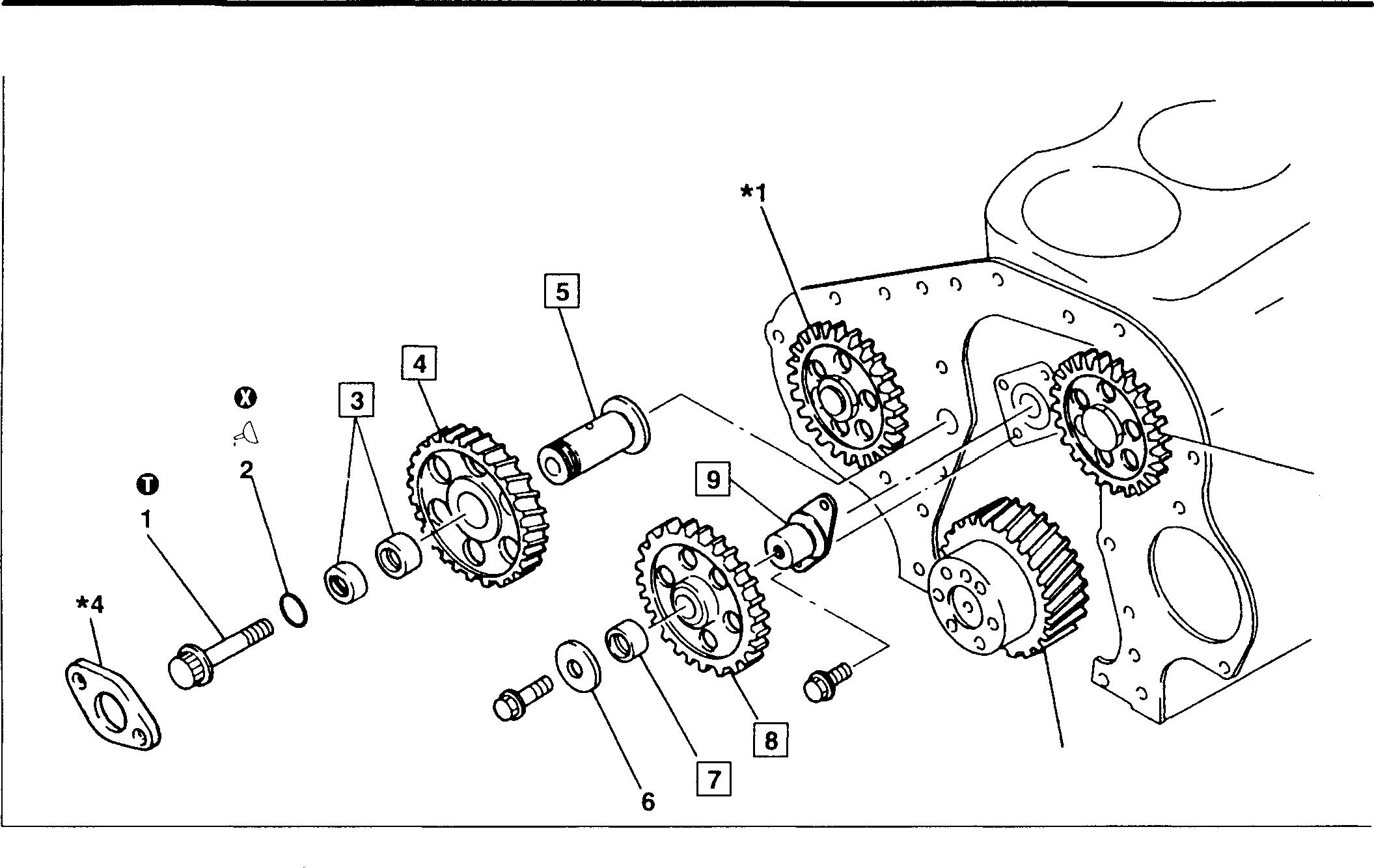
• Disassembly sequence
1 Bolt
2 O-ring
3 No.1idlergearbushing
4 No.1idlergear
5 No.1idlershaft
• Assembly sequence
Reversetheorderofdisassembly.
Service standards

6 Thrustwasher
7 No. 2 idlergearbushing
8 No. 2 idlergear
9 No. 2 idlershaft
*3
*1:Drivegear
*2: Camshaftgear CD P.11-64
*3: Crankshaftgear CD P.11-72
*4: Thrustplate CD P.11-48
0: Non-reusablepart
Standardvalue /
*2
16940
Unit:mm Location Maintenanceitem (Basicdiameterin[]) Limit Remedy - Gear BetweenNo.1idlergearandcrank- 0.07to0.20 0.35 Replace backlash shaftgear BetweenNo.1idlergearandNo.2 0.10to0.22 0.35 Replace idlergear BetweenNo.1idlergearanddrive 0.10to0.20 0.35 Replace gear BetweenNo.2idlergearandcamshaft 0.12to0.26 0.35 Replace gear 3,5 No.1idlershaft-to-gearbushingclearance [40]0.03to0.07 0.2 Replace 4 No.1 idlergearendplay 0.1to0.6 1.0 Replace 7,9 No.2idlergearbushing-to-shaftclearance [32]0.01to0.05 0.2 Replace 8 No.2idlergearendplay 0.05to0.20 0.4 Replace 11-60
0
Tightening torques
Location Parts to be tightened
Tightening torque
Unit: N·m {kgf·m}
Remarks
1 No.1 idlergearmounting bolt 14 to17 -
� Oils
Location Pointsof application Kinds Quantity
2 0-ring Engineoil Asrequired
�
Special tools

Location Toolnameandshape
IdlerGear Bushing Puller
� A B
No.1 idler
3, 7 gear bush- <j>40 <j>44 ing
No.2 idler gearbush- <j>32 <j>35 ing
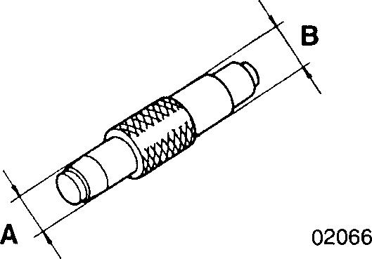
Unit: mm
Part No. Application
<NO.1> MH061228 <No.2> MH061779
Removingandfitting idler gearbushings
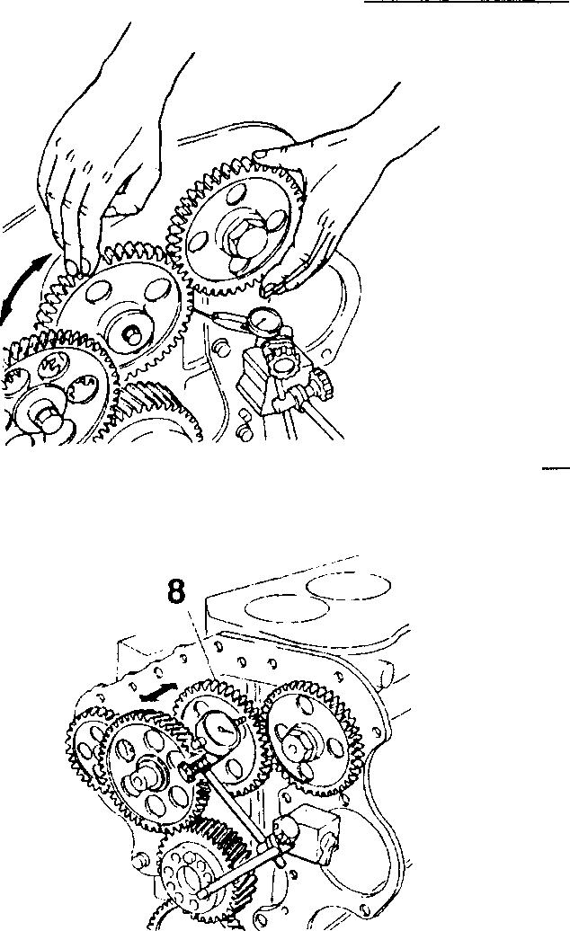
♦ Service procedure
• Pre-disassembly inspection
(1) Gear backlash
For each gearpair, measure backlash atthree or more points. If any measurement exceeds the specified limit, replace the defective part(s).
(2) No. 2 idler gear end play
Iftheendplaymeasurementexceeds thespecifiedvalue, replacethe defective part(s).
11
02068 02077
11-61
TIMING GEARS
[I][[] No. 1 idler gear bushing and No. 1 idler shaft
[Inspection]
Iftheclearance exceeds the specifiedlimit, replace thedefective part(s).
,No. 1 idler gear bushing
[Removal]
TheNo. 1 idlergear bushing3consistsoftwoparts. Pressout bothparts 'together.
A: Press
[Installation]
• Using the � Idler Gear Bushing Puller, press each part of the No. 1 idlergear bushing3into the No. 1 idler gear 4 from its respectiveside of the gear.
A: Press
• After installation, measure the clearance again. If the measurement is below the nominal value range, ream the bushing 3.
[1] No. 1 idlergearend play
Measure thedimensions shown in the illustration and determine the end play D usingthe formula shownbelow. If theend play exceedsJhe specified limit, replace the defective part(s).
D = 72.15 mm - (A + B + C)
[1][!] Installing No. 1 and No. 2 idler gears
FittheNo. 1 andNo.2idlergears4,8suchthattheiralignmentmarks ("1", "2", "3", "4") are aligned with those on the gears with which they mate.
*1 : Drive gear
*2: Camshaft gear
*3: Crankshaft gear
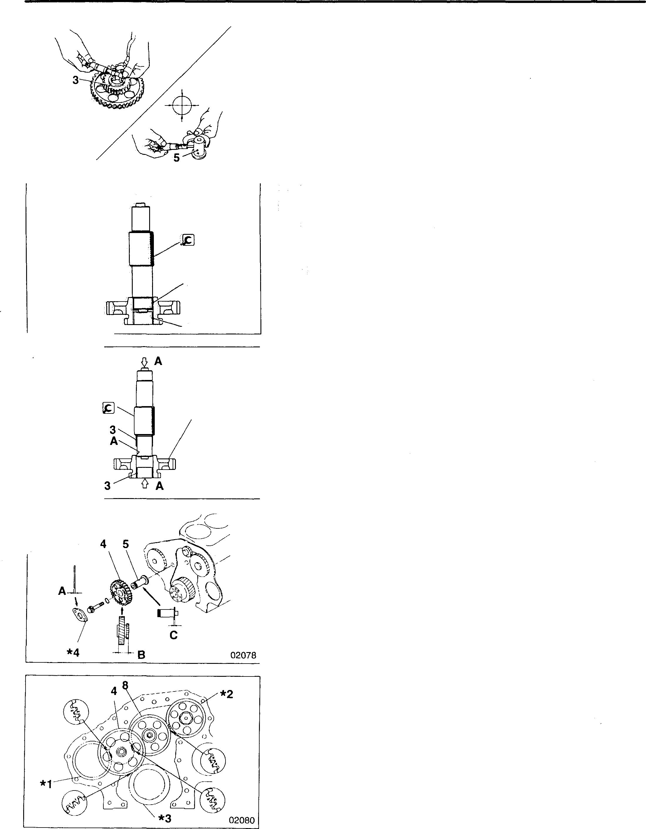
11-62 02582
02583
02584
EB {> A
3 3
4
[i) [fil No. 2idler gear bushing and No. 2idlershaft
[Inspection]
Iftheclearanceexceedsthespecifiedlimit,replacethedefectivepart(s).
No. 2 idlergear bushing [Removal]
A:Press
[Pressfitting]
• Usingthe�IdlerGearBushingPuller,presstheNo.2idlergearbushing7intotheNo.2idlergear2fromthesideofthegearwhoseinternal diameteris chamfered B.
A:Press
• Afterinstallation, measuretheclearanceagain. Ifthemeasurementis belowthenominalvaluerange, ream the No.2 idlergear bushing7.
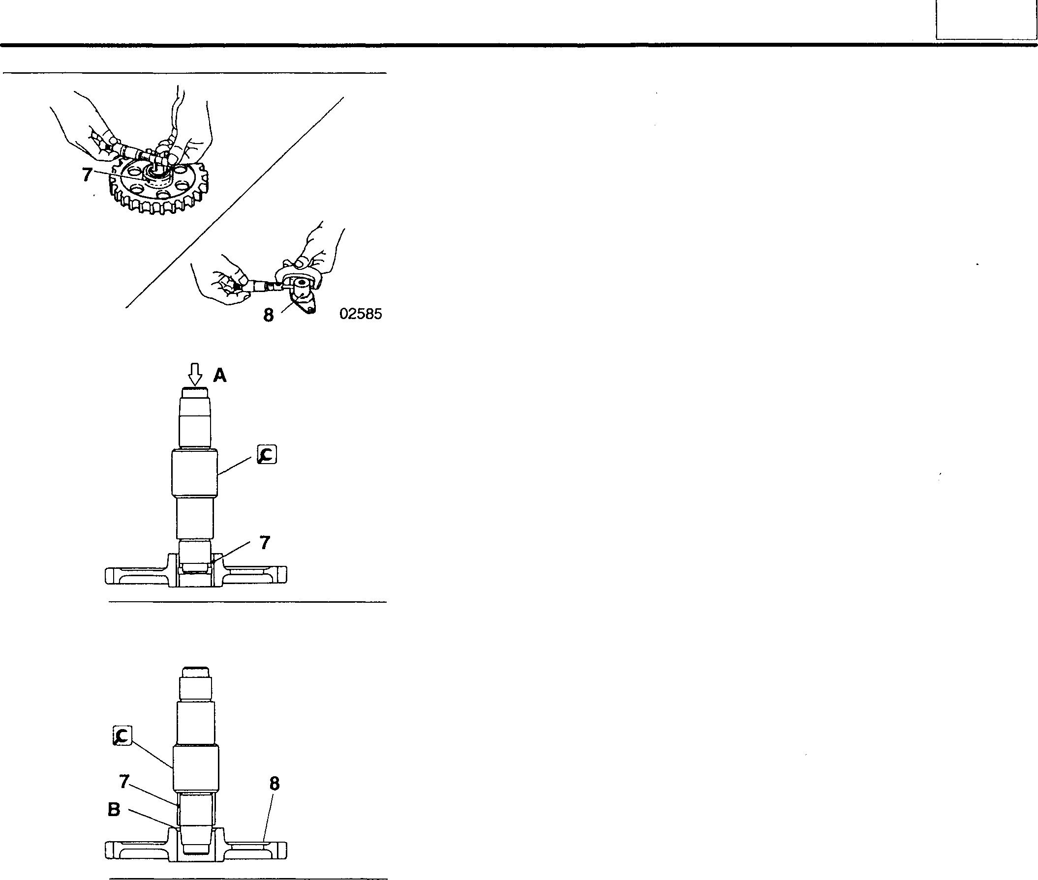
02580 ◊ A 02581
11
11-63
Mitsubishi 6D16TLEA Tadano Crane
CAMSHAFT
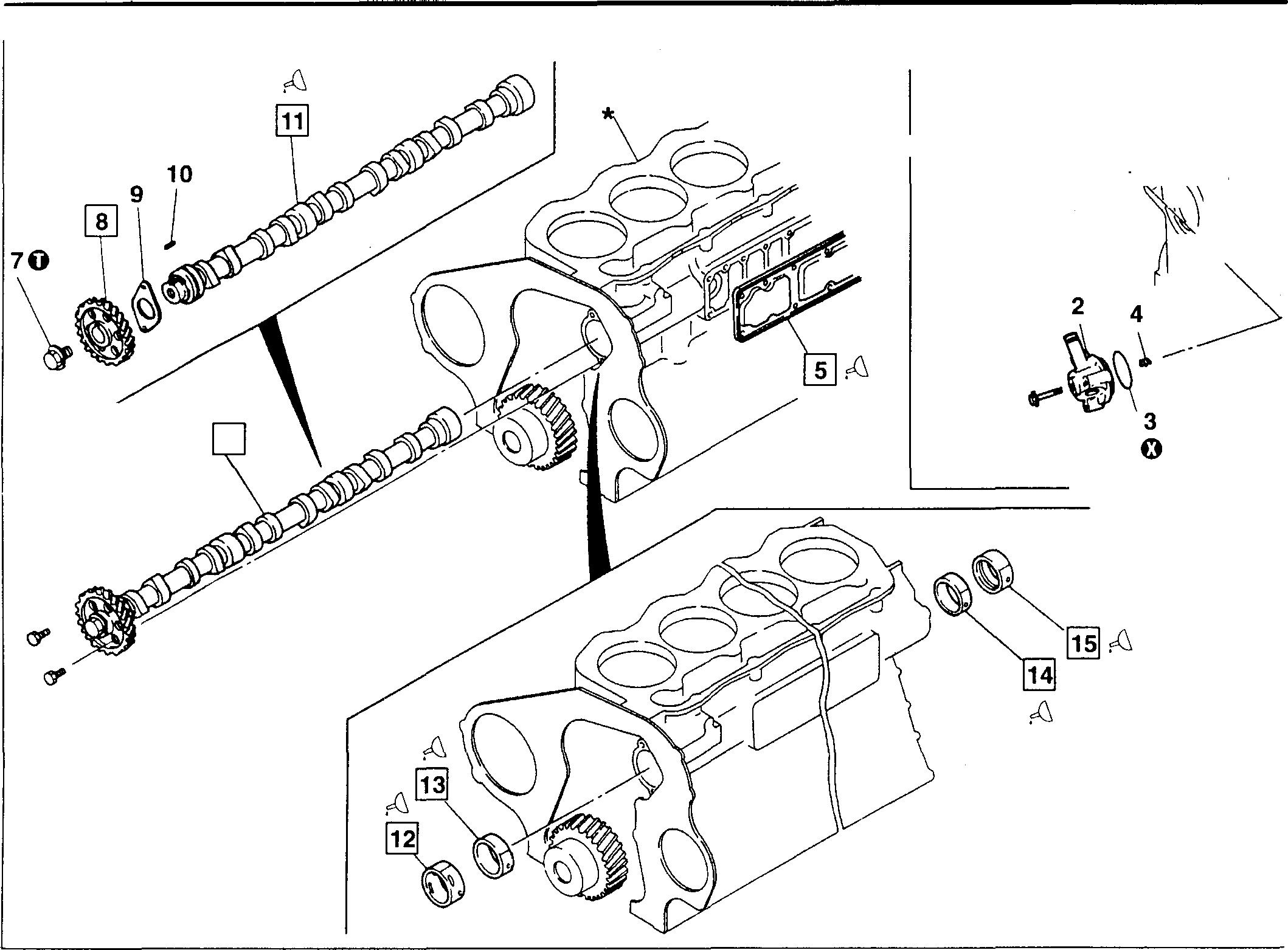
6
• Pre-disassembly inspection 0: P.11-66
• Disassembly sequence
1 Engine speed sensor <models with electric speed sensor>
2 Adapter <models with electric speed sensor>
Tachometer drive case <models with mechanical tachometer>
3 O-ring
NOTE
4 Pulserotor <modelswith electric speed sensor>
Tachometer drive coupling <models with mechanical tachometer>
5 Side cover
6 Camshaft assembly
7 Bolt
8 Camshaft gear
9 Thrust plate
• Do not remove the engine speed sensor 1 unless defects are evident.
• Do not remove the camshaft gear 8 unless defects are evident.
• Assembly sequence
Reverse the order of disassembly.
<Withelectricspeedsensor>
<Withmechanical
*: Crankcase CD P.11-72
0 : Non-reusable part
18061
-----i�JJ� ·� ir,f
0
11-64
10 Key 11 Camshaft 12 No. 4 camshaft bushing 13 No.3 camshaft bushing 14 No. 2 camshaft bushing 15 No. 1 camshaft bushing
� tachometerdrive>
Mitsubishi 6D16TLEA Tadano Crane
Servicestandards
1
0 Tightening torques
Parts to be tightened
1 Engine speedsensor <modelswith electricspeed
sensor> 4 Pulserotor <modelswith electricspeed sensor>
Oils and sealants
Location Pointsof application
1 Engine speedsensorthreads <modelswith electric speed
sensor>
5 Crankcase mounting surfaceof sidecover
to 15
surfaces of camshaftbushings
1104J
1207C
11
Unit: mm Location Maintenance item Standard value Limit Remedy (Basicdiameterin [ ])
sensor
25°C) 2.3±0.2kQ - Replace 6 Camshaftassemblyend play 0.05to 0.22 0.4 Inspect each part 11 Camshaft Camlift Inlet 6.901 6.40 Lobe height: 49.011 Base circle diameter: 42.110 Exhaust 7.680 7.18 Lobe height: 49.307 Basecircle diameter: 41.627 Bend 0.02orless 0.04 Replace 11, Camshaftjournal-to-camshaft No. 1journal [57.75] 0.05to 0.1o 0.25 Replace 12 to 15 bushing clearance No.2journal [58.00] 0.05to 0.10 No.3journal [58.25] 0.13 to 0.18 No.4journal [58.50] 0.05to 0.10
Resistance of engine speed
(at
Unit: N ·m {kgf·m}
Tightening torque Remarks
Location
29± 5.9{3.0±0.6} -
98
0}7
175
�
{1
Camshaftgearmounting bolt
{18}
Kinds Quantity
Threebond
Asrequired
Threebond
As required 11
Engineoil Asrequired 12
Inside
Engineoil Asrequired 11-65
Camshaftjournals
CAMSHAFT
[g Special tools
Tool name and shape

Part No.
MF665007
M10 X1.25
02082
.Bear!RIJIler
MH061326

CCarrn!lrr.attiBmllnimgitm:ltaller and·Extractor
� A,Cdimension
1
2
3
4
62.25
62.75
Bdimension
58.00
58.25
58.50
Unit: mm Application
Blankingplugforuse whenremovingcamshaftgear
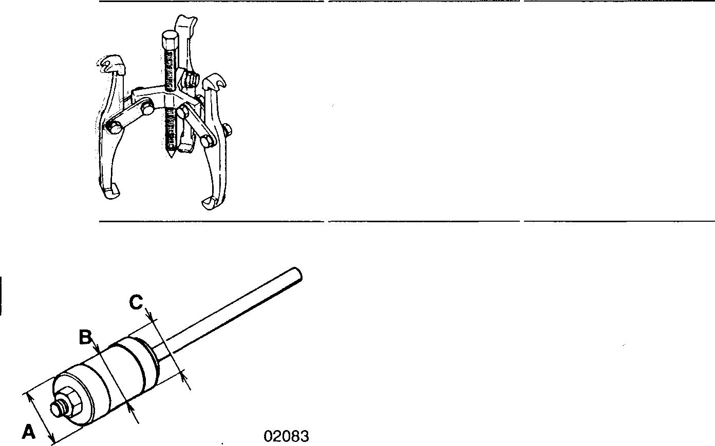
Removingcamshaft gear
02065
♦
Service procedure
MH062025
Removingandinstallingcamshaftbushings
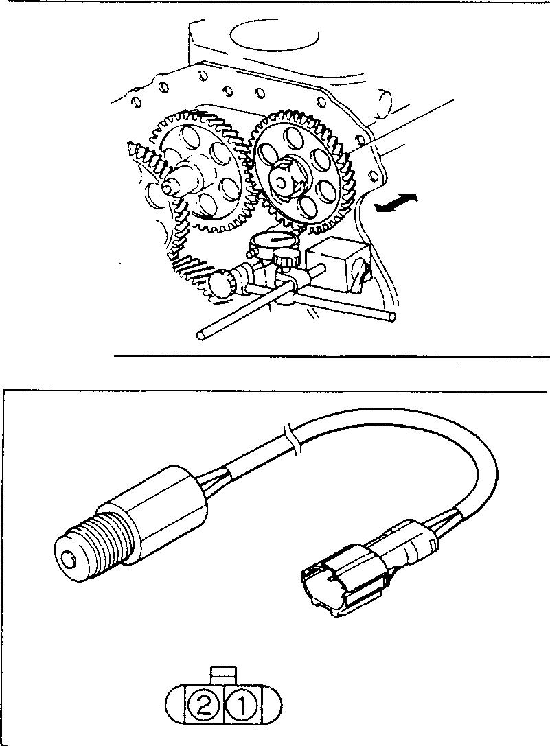
• Pre-disassembly inspection Camshaft end play
Iftheendplaymeasurementexceedsthespecified limit, replacethedefective part(s}.
OJ Inspecting engine speed sensor
<6D16-TLEA electric speed sensor>
• Measuretheelectricalresistance betweenterminalsCD andCg)_
• Ifthemeasurementisoutofspecification, replacethespeedsensor 1. [O Gr11
CAUTION_&----
Check the tightening torque of the engine speed sensor 1. If the sensor is insufficiently tightened, it may not produce signals.
Location
8
Plug
-�
12 to
<!>62.00 No.
<!>
No.
<!>62.50 No.
<!>
11-66
15 No.
<!>57.75 <!>
<I>
<I>
02084 03674
[fil Fitting side cover
• Applyaneven, unbrokenbead of sealant A to the sidecover 5.
• Fitthesidecover5ontothecrankcasewithin3minutesofapplyingthe sealantA.
CAUTION&----
• Ensure that the sealant application surface of the side cover 5 is clean before applying sealant.
• When fitting the side cover5, hold it firmly in position to prevent spreading the sealant.
• After fitting the side cover5, wait at least an hour before starting the engine.
• ApplyanewbeadofsealantA wheneverthemountingboltsofthe side cover 5 have been loosened.
[§] Camshaft assembly
[Removal]
• Whenremovingthecamshaftassembly6, takeoffthesidecover5and supportthecamshaftbyhand.
• RemovetheboltsAfromthecamshaftgearholes,thenslowlyremove thecamshaftassembly6.
CAUTIONLt._-------------
Takecarenottodamagethe camshaft bushings12to 15 when removing the camshaft assembly 6.
[Installation]
• Before installingthecamshaftassembly 6, measuretheend play betweenthethrustplate 9 andcamshaft 11.
• Ifthe measurementexceedsthe specifiedlimit,replacethedefective part(s).
• With thealignment marks lined up onthecamshaft gear 8 and No. 2 idler gear, fitthecamshaftassembly. OJ P.11-57
[!] Camshaft gear
[Removal]
CAUTIONLt._---------
The camshaft gear 8 must be removed with the appropriate special tools. Do not tap off the camshaft gear since this would damage it.
�a:Gear Puller
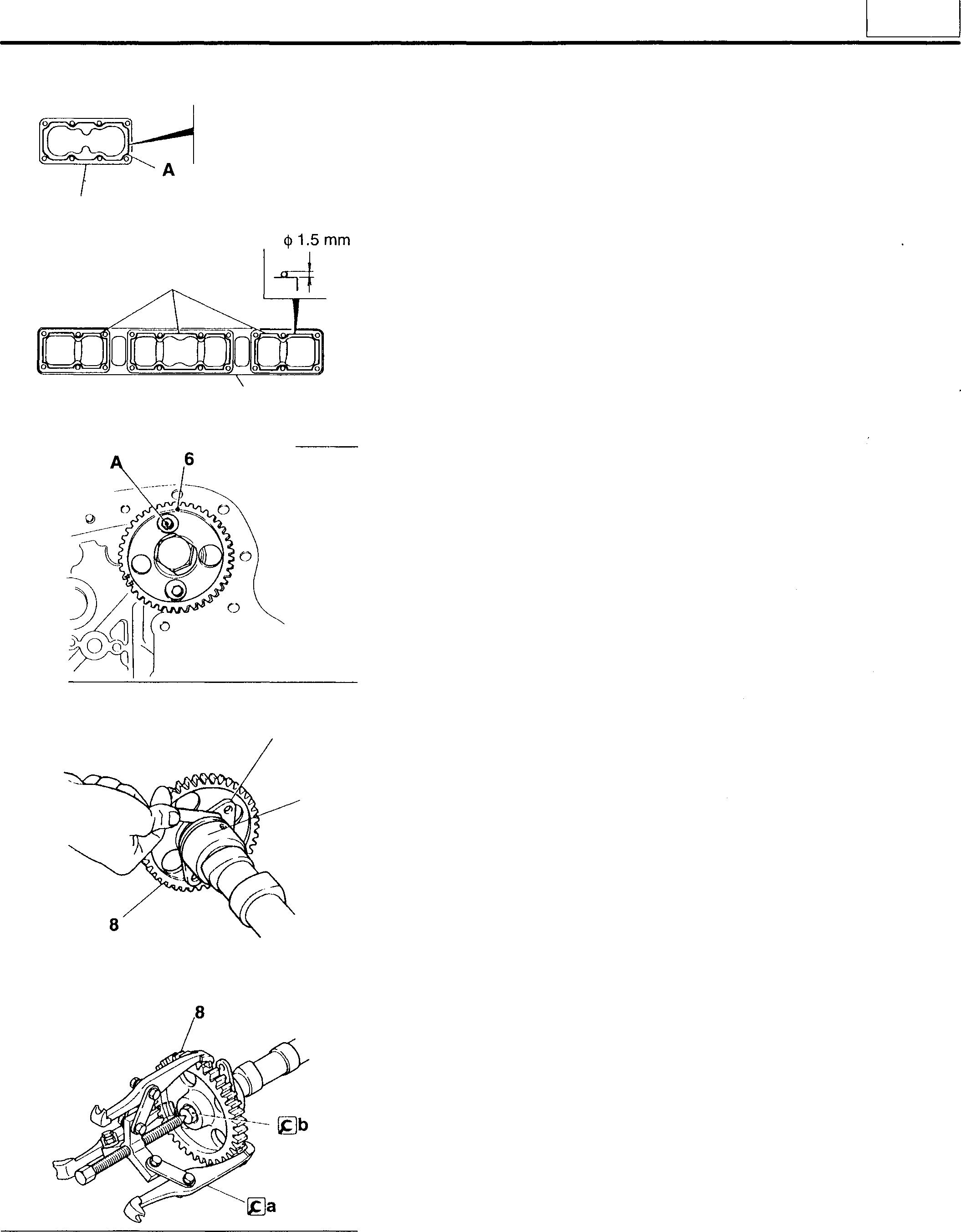
�b: Plug
<)> 1.5 mm � 5 6D16-TLEA A ----5 ( 18062 02086 9 11 02092 02088 11
11-67
CAMSHAFT
A
[Installation]
• Fitthecamshaftgear8ontothecamshaft11inthedirectionillustrated.
• Donot forgettofit the key10.
[DJ Inspecting camshaft
(1) Camlift
Ifanybasecircle-to-lobeheightdifferenceislessthantherequiredvalue, replacethe camshaft11.
NOTE
Sincethecamsaretapered,theymustbemeasuredattheposition Ashowninthediagram.
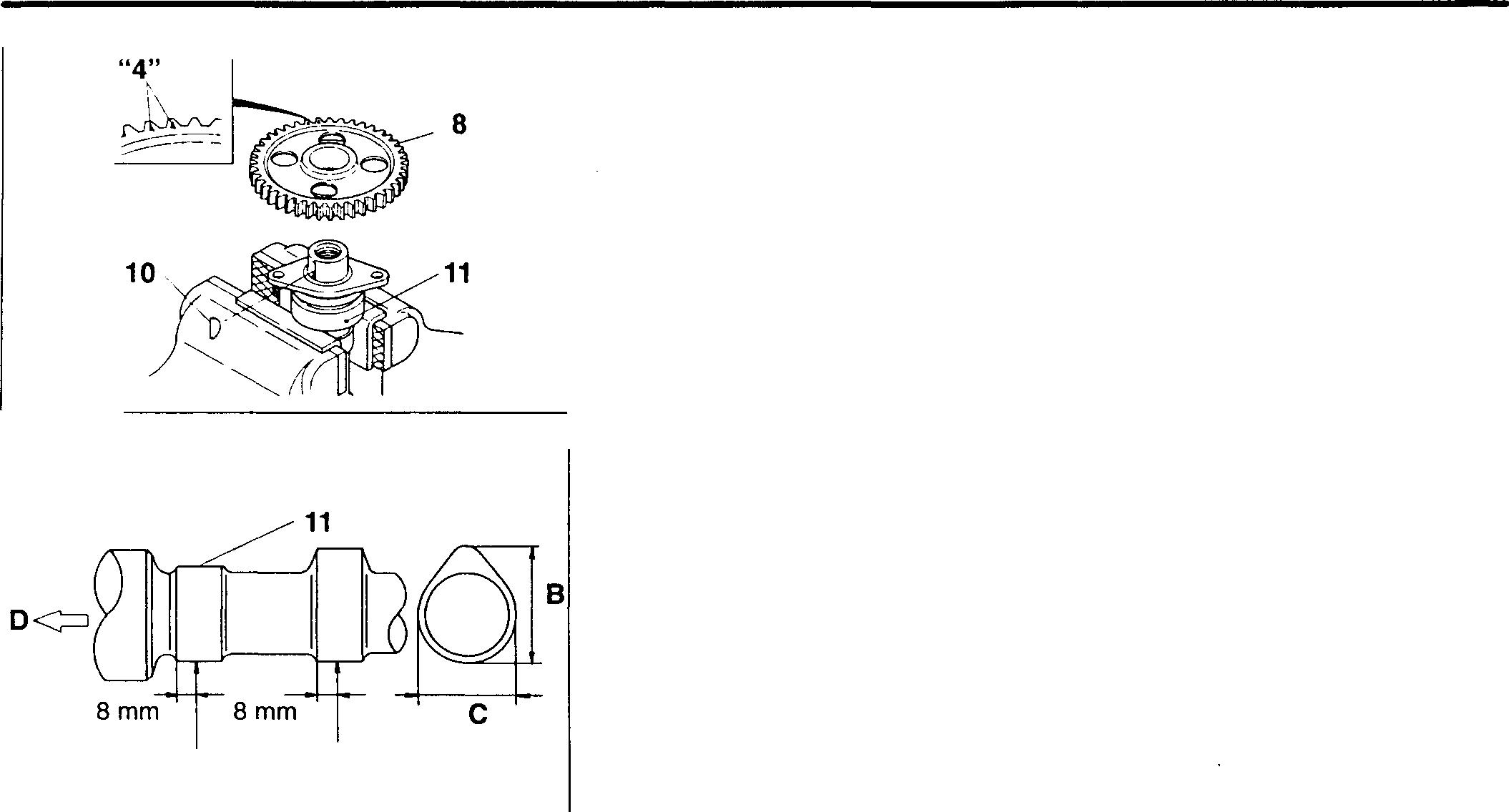
B:Lobeheight
C: Basecircle diameter
D: Frontofengine
(2) Camshaft bend
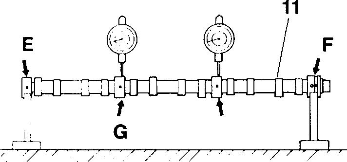
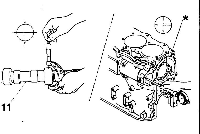
Supportthecamshaft11atitsNo. 1 journalEandNo.4journalF,then takemeasurementsattheNo.2journalGandNo.3journalH.Ifeither measurement exceeds thespecified limit, replacethe camshaft.
NOTE
Turn the camshaft 11 through one revolution. One-half of the dial indicator reading representsthe camshaft's bend.
[DJ to� Camshaftandcamshaft bushings
[Inspection]
Ifanyclearanceexceedsthespecifiedlimit,replacethedefectivepart(s).
NOTE
Measure the camshaft bushings 12 to 15 with the camshaft installed in the crankcase*.
A
11714
H ✓-/ /, //// // / / 04108 02093 11-68
02090
"1", "2" "3", "4"
Camshaft bushings
Removal and installation of camshaft bushings should be carried out using the [&] Camshaft Bushing Installer and Extractor. Each guide of the toolisstamped withan identification mark ("1", "2", "3", "4") in the position shown. Use correct adapter and/or guide piece to remove and install a bushing according to the table below.
Bushing No. (from front of engine) Identification mark
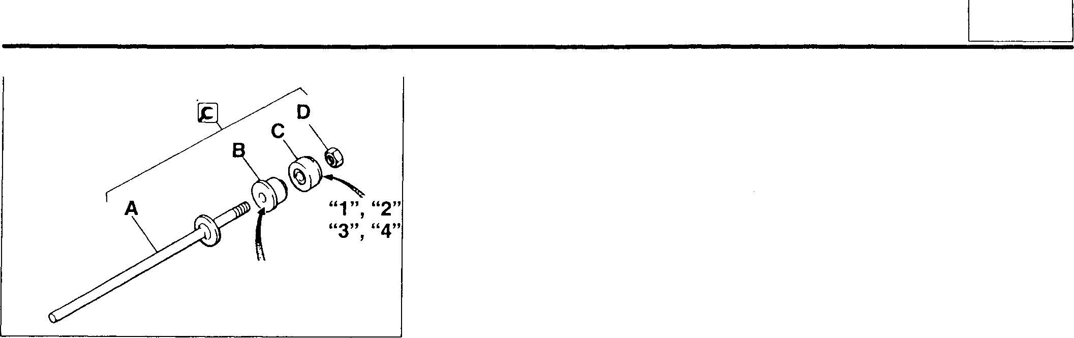
<Components of [&] Camshaft Bushing Installer and Extractor>
A: Rod
B: Camshaft bushing adapter
C: Guide piece
D: Nut
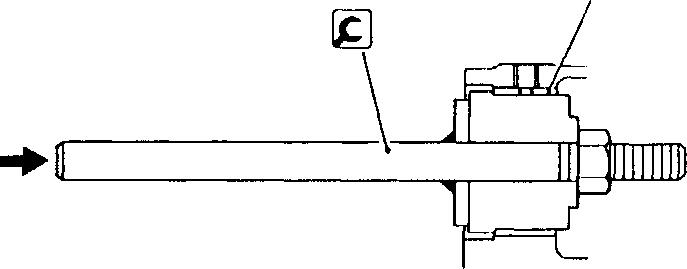
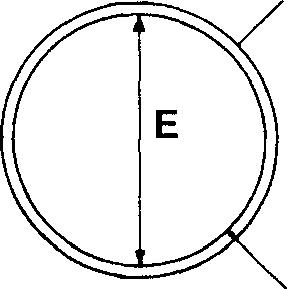
"1", "2" "3", "4"
[Removal]
Remove the No. 4 and No. 3 camshaft bushings 12, 13 from the rear of the engine. Remove the No. 2 and No. 1 camshaft bushings 14, 15 from the front of the engine.
[&]: Camshaft Bushing Installer and Extractor
[Installation]
• IdentifytheNo. 1 toNo. 4camshaftbushings12to15fromtheir identificationmarks ("1","2","3","4")inaccordancewiththetablebelow. Ifany bushing'sidentification markisunclear, identifythe bushingfrom itsinternal diameter E.
Bushing No. Identificationmark Internal diameter (fromfrontof engine) (mm)
13020 12 to 15
12 to 15 02094 11741 11
No.1 1 No.2 2 No.3 3 No.4 4
No.1 1 q>57.75 No.2 2 q>58.00 No.3 3 q>58.25 No.4 4 q>58.50 11-69
CAMSHAFT
• Install the bushings 12to 15 by using all components of the �CamshaftBushing Installerand Extractor (rodA, camshaft bushingadapter B, guide piece C and nut D).
• Installthecamshaftbushings 12to15inthefollowingorder: No. 3, No. 4, No. 2 and No. 1.
NOTE
•tnstalltheNo.3andNo.4camshaftbushings12,13fromtherear of•the engine. Install the No. 1 and No.2 camshaft bushings 14, 15 from the frontoftheengine.
• Ensure that the oil holes F in the No. 1 and No. 4 camshaft bushings 15, 12 are aligned with the oil holes Gin the crankcase. With the No. 4camshaftbushing, ensurealsothatthelongeroilhole Histowardthe :rear of the engine.
J: Bushing clinch joint
�: Camshaft Bushing Installer and Extractor
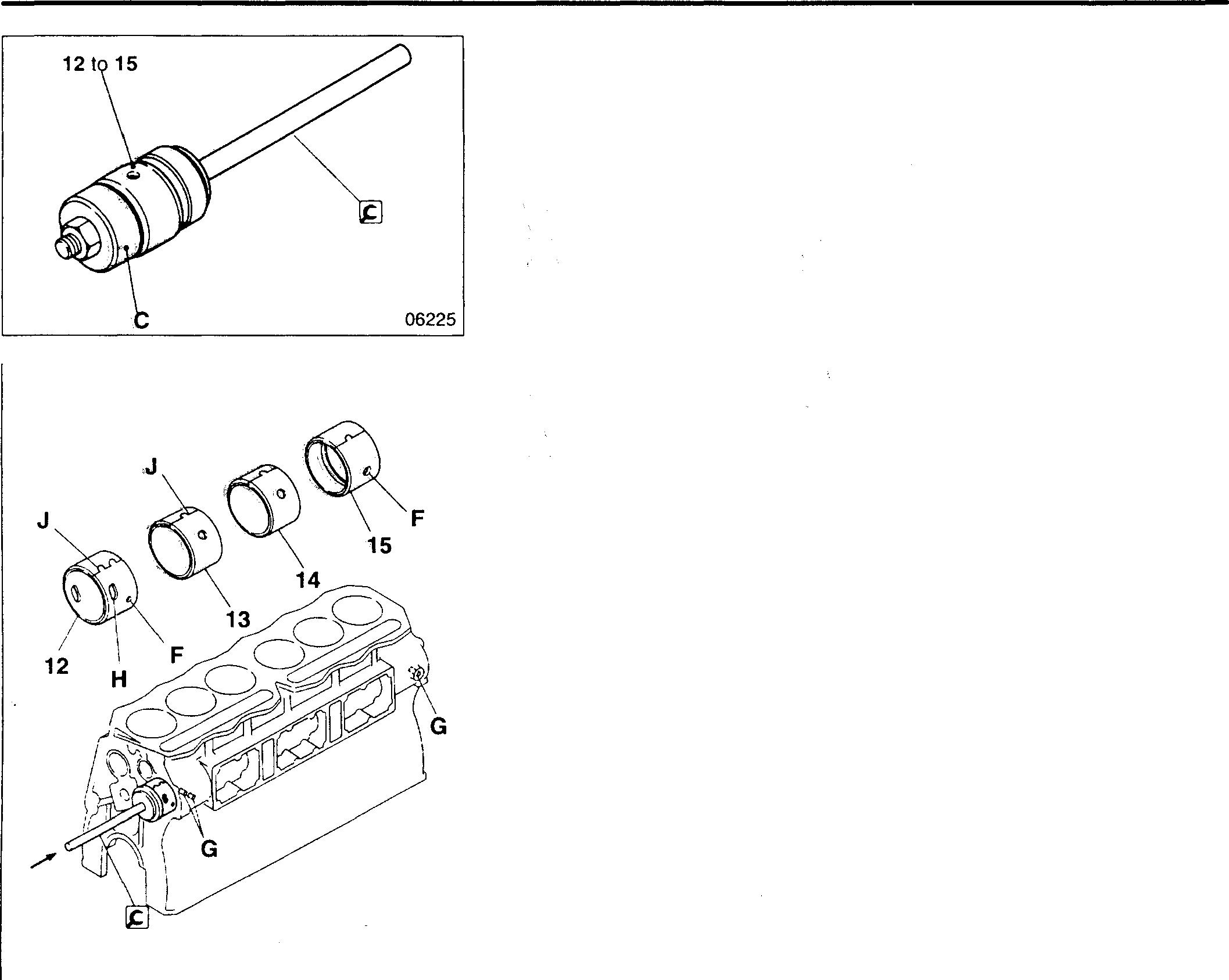
04109 11-70
11
11-71
MEMO
Mitsubishi 6D16TLEA Tadano Crane
CRANKSHAFT AND CRANKCASE 0
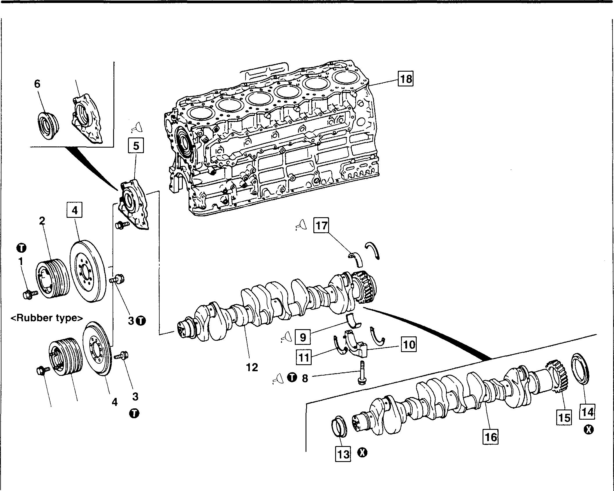
• Pre-disassembly inspection 0::: P.11-75
• Disassembly
� 7
type> 1 0 2
<Viscous
sequence 1 Bolt 2 Crankshaftpulley 3 Bolt 4 Torsionaldamper 5 Front coverassembly 6 Frontoil seal 7 Frontcover
Reverse
11-72 8 Bolt 9 Lowermainbearing 10 Mainbearing cap 11 Thrustplate 12 Crankshaftassembly 13 Frontoilseal slinger 14 Rearoil sealslinger 15 Crankshaft gear 16 Crankshaft 17 Uppermainbearing 18 Crankcase 0: Non-reusable part 18070
• Assembly sequence
the orderofdisassembly.
6D16TLEA
engine parts contact: Email: engineparts2@gmail.com Phone: 269 673 1638 Text: 267 760 8652
Mitsubishi
Tadano Crane
Mitsubishi 6D16-TLEA Tadano
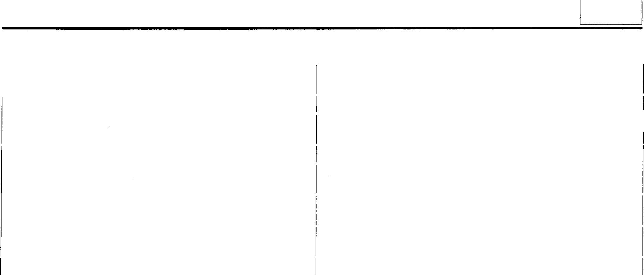
0
torques
r0, Oils and sealants
Crankcasemounting surfaceoffrontcoverassembly
Frontoilseal lip
Bolt threads
11 Service standards Unit: mm Location Maintenance item Standard value Limit Remedy (Basic diameter in [ ]) 9, 17 Mainbearing Oil clearance 0.05to0.10 0.15 Replace Spanwhenfree - Lessthan Replace 85.5 16 Crankshaft Endplay 0.10to0.25 0.4 Replace Bend 0.05 orless 0.1 Corrector replace Pin andjournal Roundness 0.01 orless 0.03 Correct or replace Cylindricity 0.006 orless - Correct or replace 18 Distortionofcrankcasetop surface 0.07orless 0.2 Replace
Unit: N·m {kgf·m} Location Parts to be tightened Tighteningtorque Remarks 1 Crankshaftpulleymounting bolt 185(19}3 Torsionaldampermounting bolt 67 {8}8 Mainbearingcap mounting bolt 67 {8} +90° • Wet • Can bereused up to3 times
Tightening
Location Points
application Kinds Quantity
Threebond
Asrequired 6
Engineoil As required 8
Engineoil Asrequired 9,
Engineoil Asrequired 11-73
of
5
1207C
17 Mainbearinginside surfaces
CRANKSHAFT AND CRANKCASE
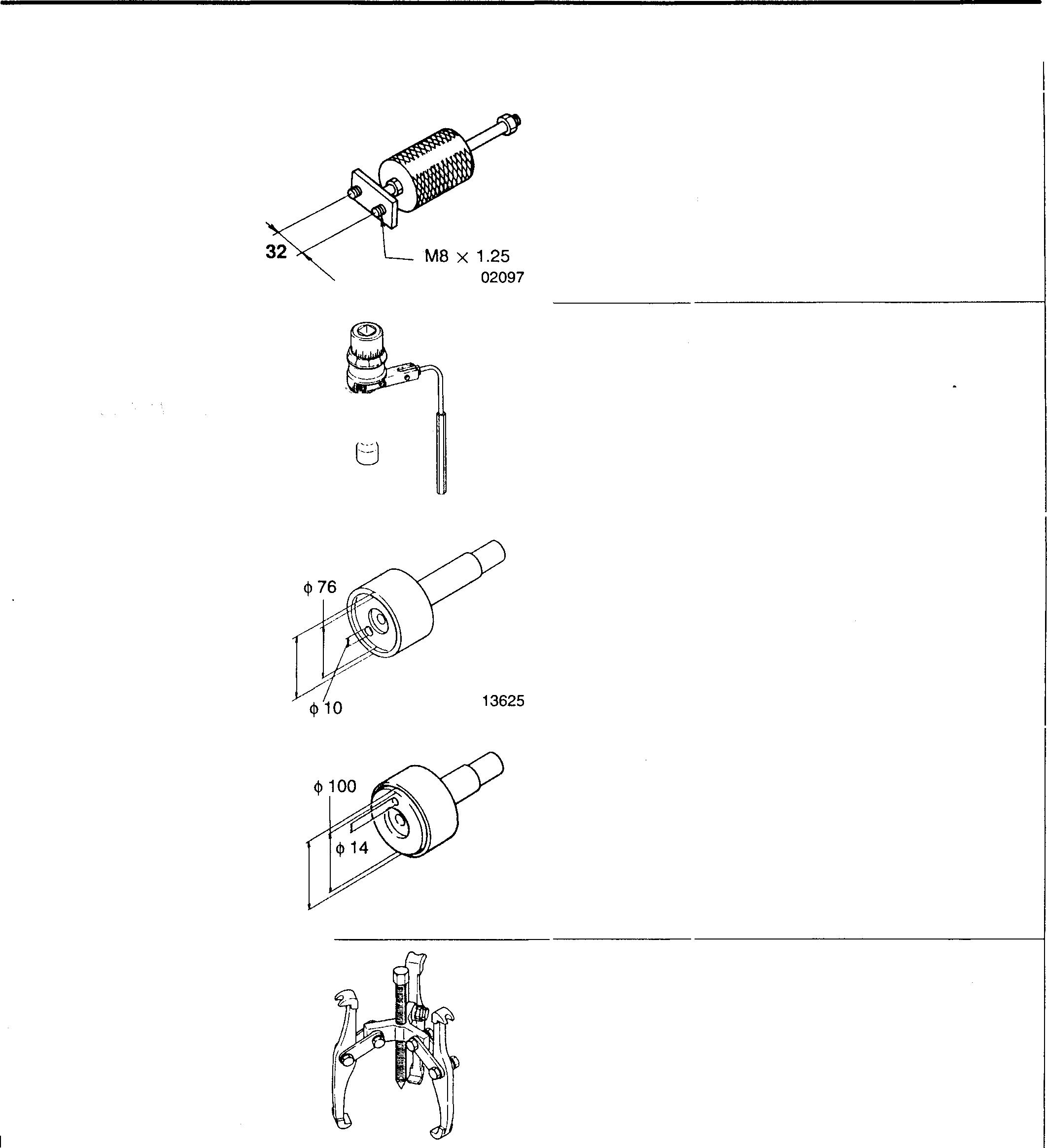
Removingmainbearingcaps
Fittingmainbearingcaps
Installingfrontoilseal
Installingrearoilseal slinger
<!>105.4
Removingcrankshaftgear
� Special tools Location 10 13 14 15 11-74 Main Bearing Cap Extractor Socket Wrench
Front OilSeal Slinger Installer
Tool name and shape Part No. MH061189
01984 MH062710
Rear OilSeal Slinger Installer Gear Puller
MH061560
<!>100 MH061470
02051
02065 Unit: mm Application
MH061326
Mitsubishi 6D16-TLEA Tadano
♦ Service procedure
• Pre-disassembly inspection
Crankshaft assembly end play
If the measurement exceeds the specified limit, replace the defective part(s).
[!] Torsional damper
<Viscous type>
CAUTION&_-------------
Leakageofsiliconoilfromthe caulkedseam A cancal,lsetheviscous-type torsional damper to stop functioning. Note the following points:
• Check that the caulked seam is free of gouges and other damage.
• Do not submit the torsional damper to shock by striking it with a hammer or dropping it.
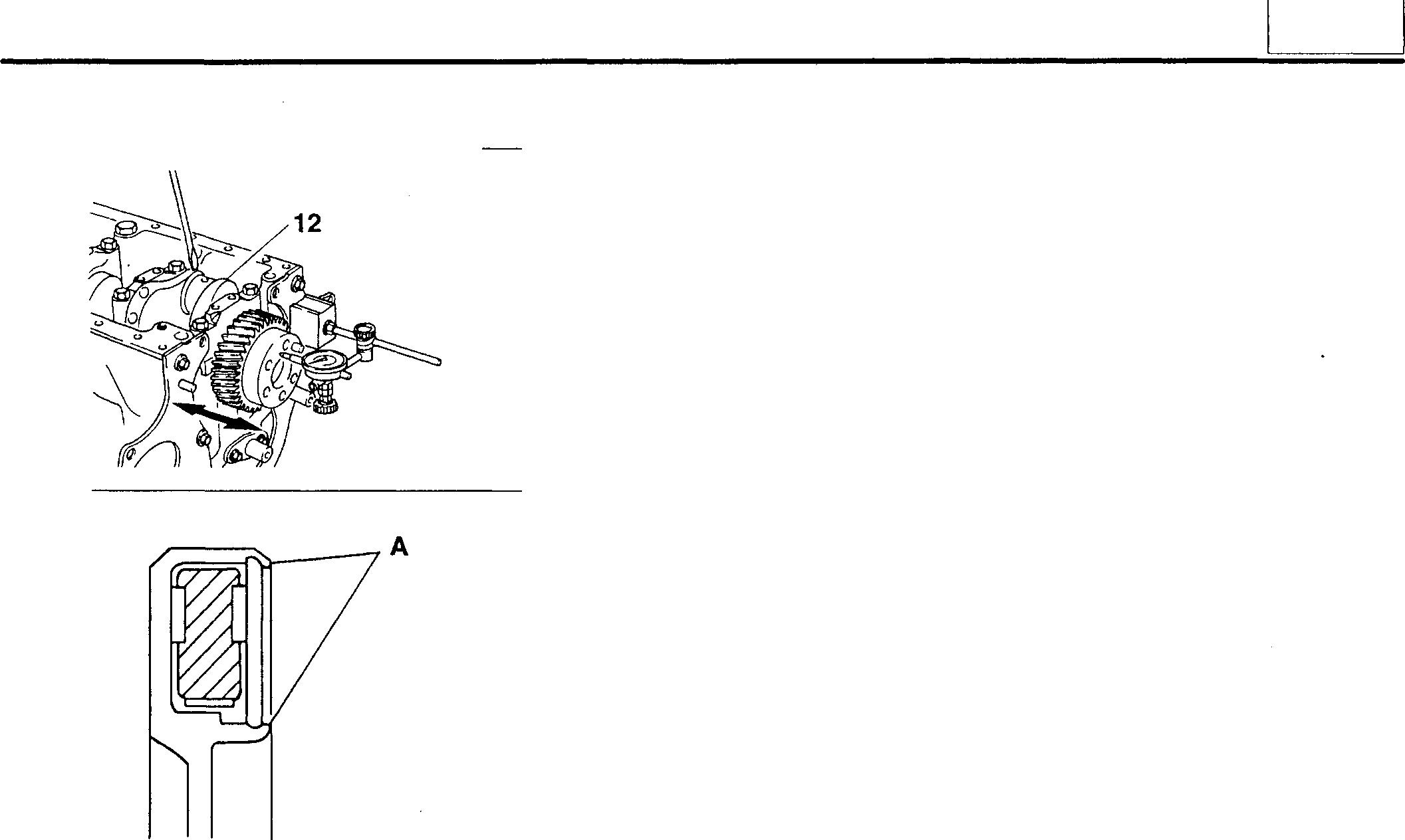
• Do not roll the torsional damper or stack it with other units.
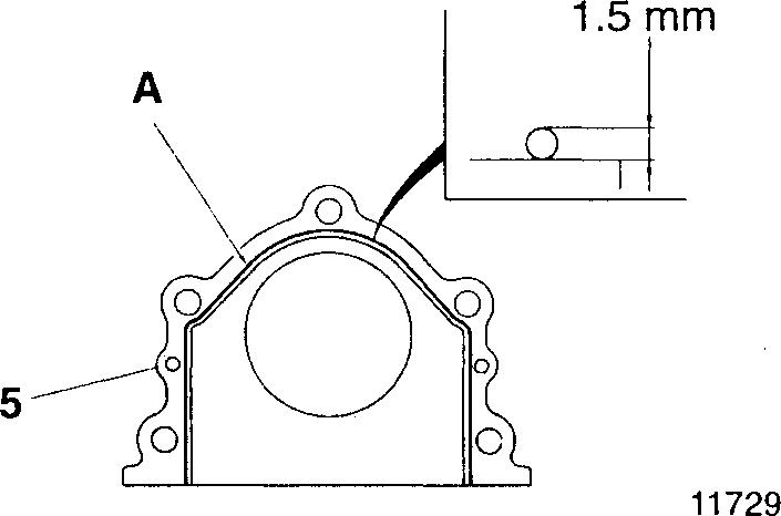
[]] Installing front cover assembly
• Applyaneven,unbrokenbeadofsealantAtothematingsurfaceofthe front cover assembly 5 tobe mounted to thecrankcase 20.
• Fitthefrontcoverassembly5 ontothecrankcase 20within3minutes ofapplying the sealant A.
CAUTION&_--------------
• Ensure that the sealant application surface of the front cover assembly 5 is clean before applying sealant.
• When fittingthe front cover assembly 5, hold it firmly in position to prevent spreading the sealant.
• After fitting the front cover assembly 5, wait at least an hour before starting the engine.
• Apply a newbead ofsealant A whenever the mounting bolt of the front cover assembly 5 have been loosened.
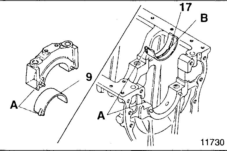
[fil [Izl Main bearings
[Installation]
Install the main bearings 9, 17 such that their lugs A fit into the correspondinggrooves.
CAUTION&_-------------
The uppermainbearing 17hasanoilhole 8. The lowermainbearing9 hasnooilhole.Takecarenottoconfusetheupperand lower parts.
02098 14933
11
11-75
CRANKSHAFT AND CRANKCASE
[Inspection]
CAUTION&--------------
• Do not attemptto manually expand either bearing 9, 17 if its span is insufficient.
• Upper and lower bearings 9, 17 must be replaced as a set.
(1) Span when free
Ifeitherbearing'sspanwhenfreeexceedsthespecifiedlimit, thebearings 9, 17 must be replaced.
(2) Main bearing-to-crankshaft clearance
•Fit the upper main bearing 17 into the crankcase 18 and the lower mainbearing9 into themainbearingcap10. Then, tighten thebolts 8 to their specified torque.
• Measure the internal diameters of the main bearings 9, 17 and the outside diameter A of the crankshaft journal. If the clearance exceeds the specified limit, replace the defective part(s).
[!QI Main bearing caps (Removal]
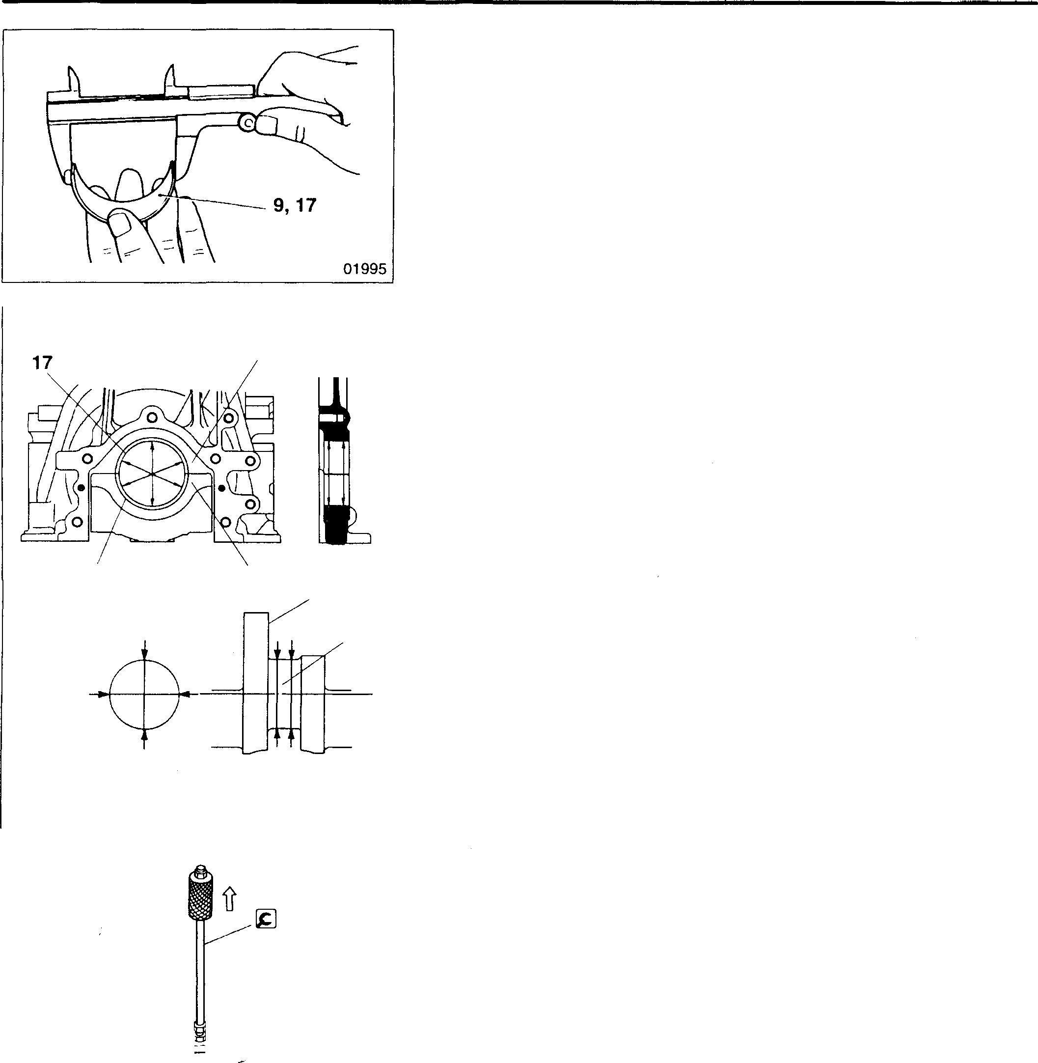
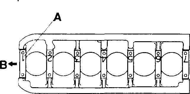
[Installation]
• Startingat thefrontof the engine B, fit the main bearingcaps 10 in the orderofthe numbers A embossed on them and such that the numbers are in the positions illustrated.
• The bolts 8 can be reused only three times. Before fitting the bolts, makeapunchmarkontheheadof eachbolttoindicatetimesofreuse.
CAUTION,&--------------
lf any bolt already has three punch marks, it must not be reused any more; replace it with a new one.
ll-76 18 9 10 16 A 02104 ��- 10 II �n:11 \ \ 02100 02103
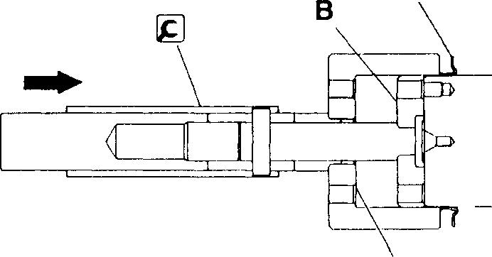
• Tightenthebolts8tothespecifiedtorque. Then, turntheboltsfurther inaccordancewith thefollowingprocedure:
• Turntheholder CoftheI&] SocketWrench counter-clockwiseto tensionthebuilt-inspring.
D: Socket
E:Rod
F:Rod (extension)
• Setthesocketwrenchsuchthatthebuilt-inspringforceforcestherod Fagainstthecrankshaftassembly12.
• On theholderC, selecttheinscribedline G thatiseasiestto see.
• Usingtheselectedlineasareference,turnthesocketD90° clockwise. (Onegradationonthescale H represents5°.)
CAUTION,&.-------------
Since the boltsutilize theplastic region tightening method, they must not be tightenedfurther after thisprocedure.
[iJ Installingthrustplates
Fitathrustplate 11 oneachsideofthemainbearingcaps10andatthe rearendofthecrankcase18such that the oil grooves Aareon the outside.
B: Locatingpin
NOTE
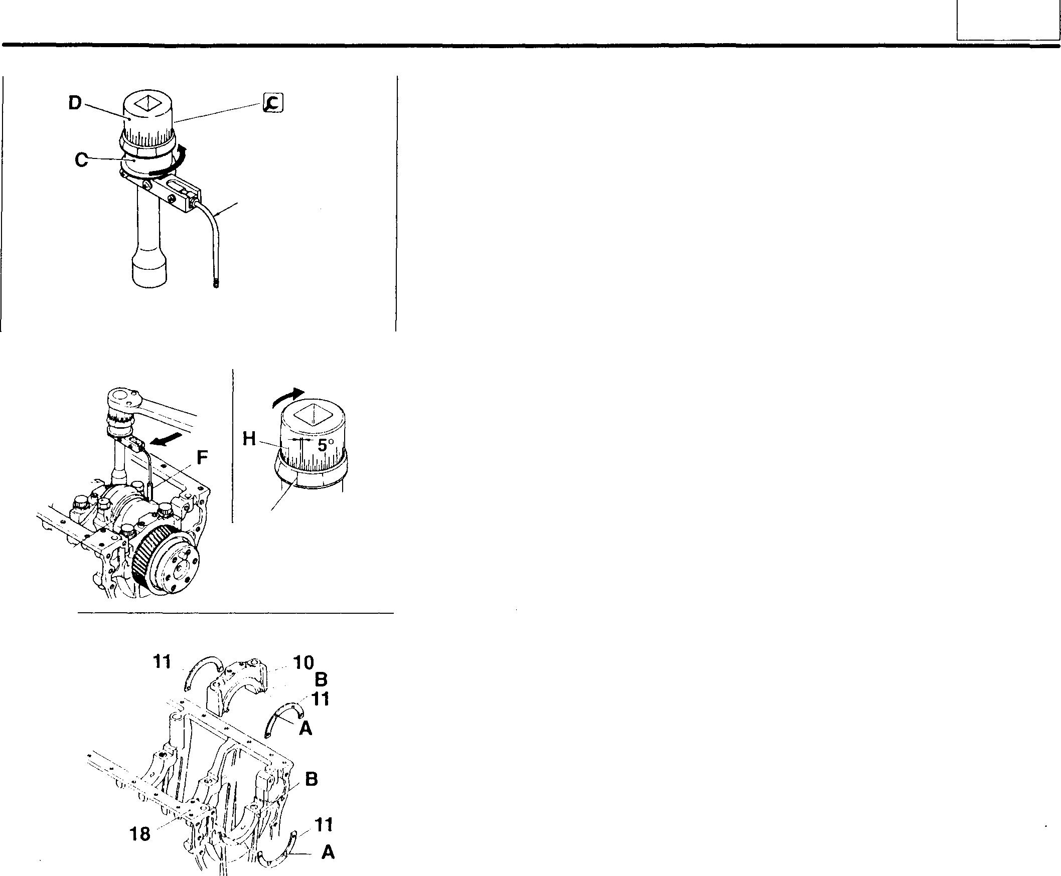
If oversize thrustplates11 are used, theymust be fitted on both sides of the bearing caps 10. Ensure that the bearing cap rear thrustplatesandtherearmostthrustplateinthecrankcase18are thesamesize.Note,however,thatthefrontandrearthrustplates on each bearingcapmay beofdifferentsizes.
� Installingfrontoilsealslinger
UsingtheI&]FrontOilSealSlinger Installer, drivethefrontoilsealslinger 13 onto the crankshaft 16 until the tool's end face A is pressed firmly againsttheguide B.
/ 12 E �/F G � 01991 12829 11731 13 ' ;A 16 11969 11
11-77
CRANKSHAFT AND CRANKCASE
� Installing rearoil seal slinger
Using the�Rear Oil Seal Slinger Installer, drive the rear oil seal slinger 14 onto the crankshaft 16 until it is pressed firmly against the end face A of the crankshaft gear 15.
[§ Removingand fittingcrankshaftgear
<M0dels without flywheel PTO> [Removal]
CAUTION.&_-----
Donottapoffthecrankshaft gear 15 since this could damage it.
�: Gear Puller
[Installation]
• Using a piston heater orthe like, heat the crankshaft gear 15to a temperature of approximately 100°c.
• Align the locating pin A on the crankshaft 16 with the notch B in the crankshaftgear 15. Then, drivethegearintoposition bystrikingitsend face with a plastic mallet.
<Models with flywheel PTO>
[Removal]
Screw the flywheel mounting bolts D evenly into the threaded removal holesCinthecrankshaft 16.Alternatively, removethecrankshaftgearusing the�Gear Puller.
CAUTION.&_-----
Do not tap off the crankshaft gearsincethis could damage it.
[Installation]
• Using a piston heater or the like, heat the crankshaft gear 15 to a temperature of approximately 100°c.
• Align the locating pin A on the crankshaft 16 with the dowel pin B on the crankshaft gear 15. Then, drive thegear into position bystriking its end face with a plastic mallet.
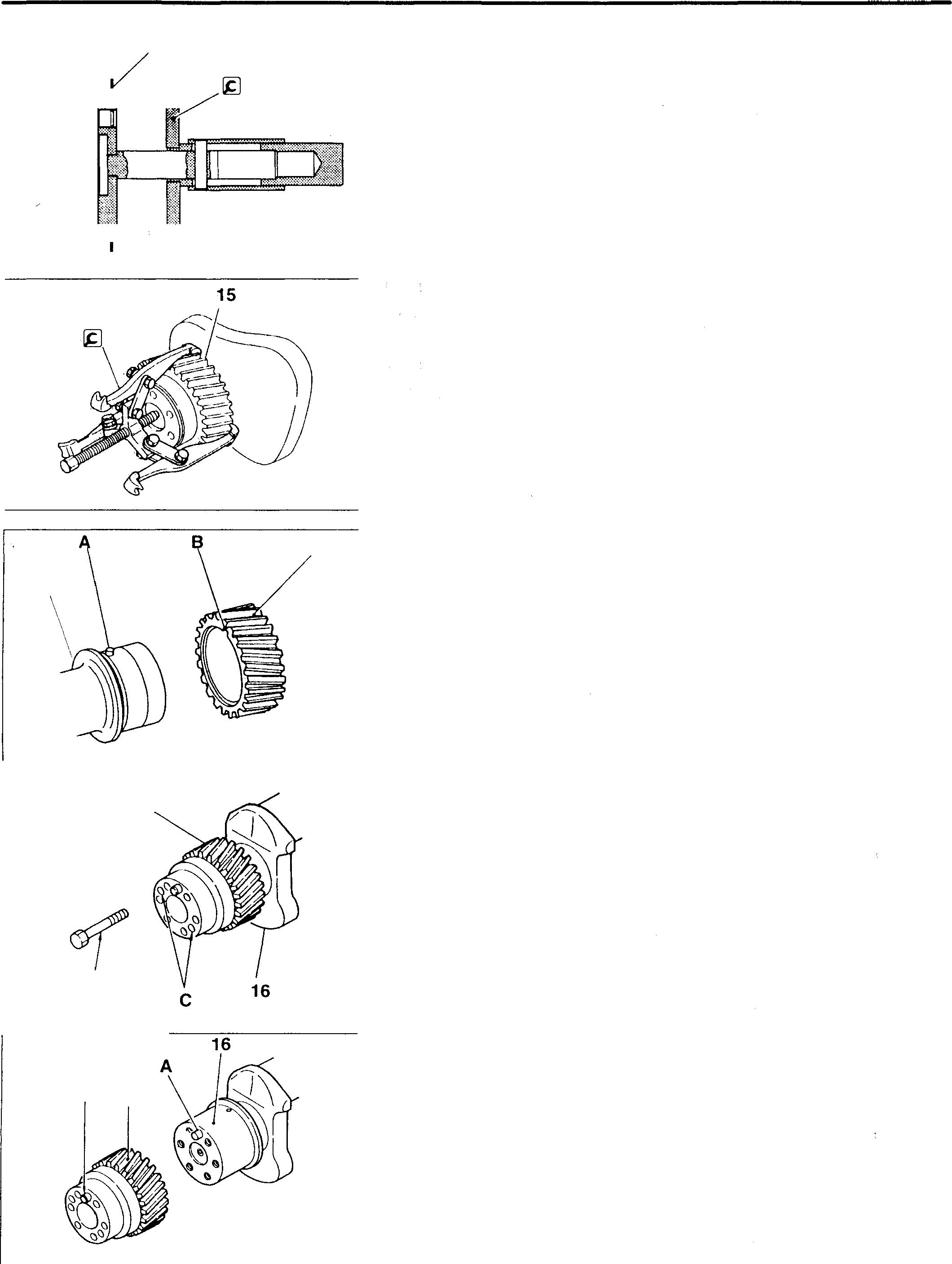
A 14 :_-i-� i /i, 1��-7!:'E:Emtill 16 15 D B 15 11-78 .. 02063 02110
02111
02113
15
02112
////, ///, / / /_, /// ///
� Crankshaft
[Inspection]
(1) Roundness and cylindricity of crankshaft journal and pin If either measurement exceeds the specified limit, replace the crankshaft 16 or grind it to undersize.
(2) Bend
• Supportthecrankshaft 16 at its No. 1 journalA and No. 7journal B. Measure theextent of bendingin the crankshaft at the centre of the No. 4journal C.
• If the measurement exceeds the specified limit, replac!:) the crankshaft.
NOTE
With the dial indicator applied to the centre journal, turn the crankshaft16 through one revolution. One-half of the dial indicator reading represents the extent of bending.
[Rectification]
NOTE
If the crankshaft 16 is rectified by grinding, the main bearings 9, 17 must be replaced with undersized ones.
• Grind such that the centre-to-centre distance F between thejournal D and pin E does not change.
F:57.5 �ggJ;mm
• Grind such that the journal width G and pin width H do not change.
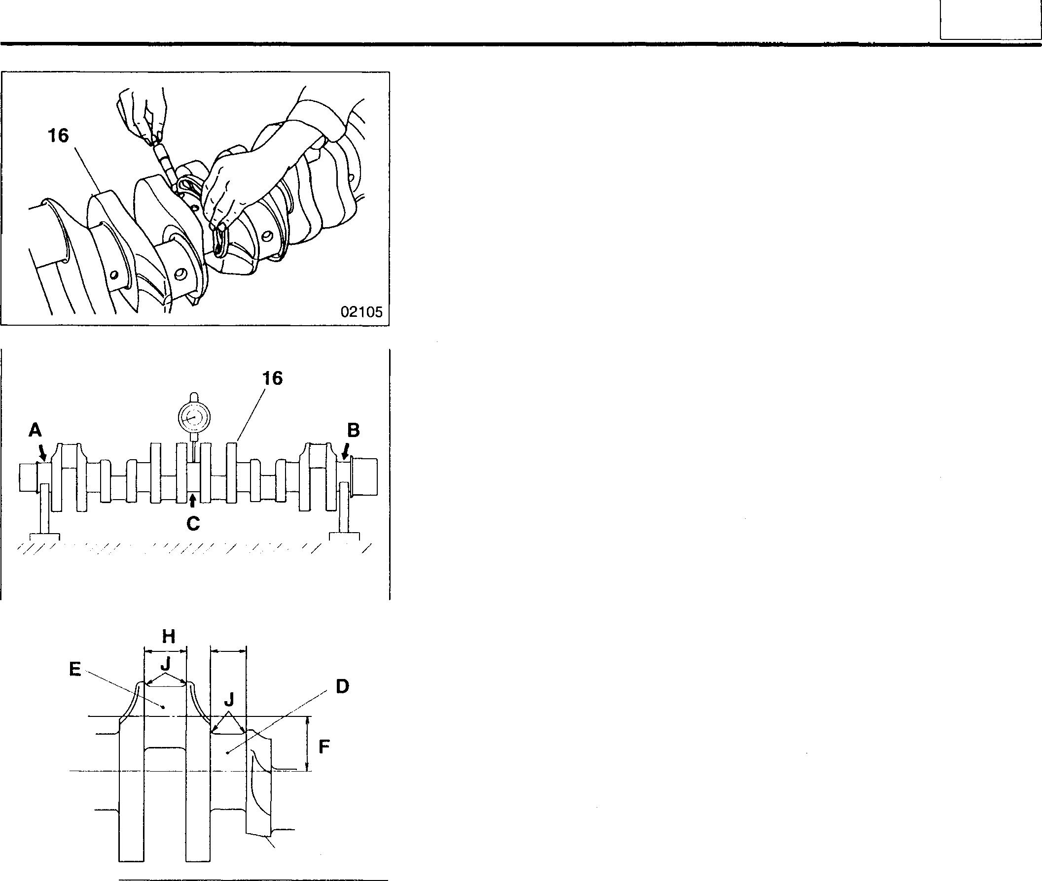
G:37 mm
H:42 +g-2 mm
• Finish the corner fillet smoothly and to the specified radius J.
J: R4 ±0.2 mm
• Carryoutamagneticinspectiontocheckforcrackscausedbygrinding. Also, checkthattheShorehardnessofthesurfacehasnotdroppedbelow Hs 75.
11
G
16 04110 02107
11-79
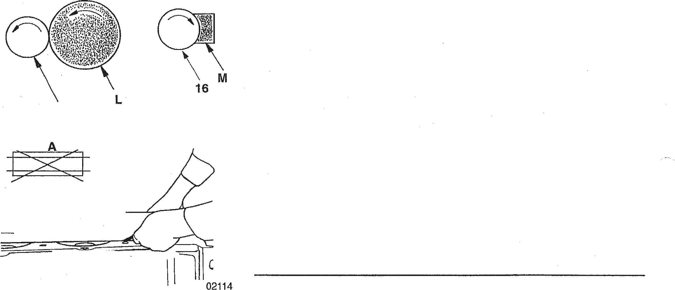 Mitsubishi 6D16TLEA
GROUP 12

LUBRICATION SPECIFICATIONS ............................................ 2 STRUCTURE AND OPERATION ............................... 3 TROUBLESHOOTING......................................... 11 ON-VEHICLEINSPECTIONAND ADJUSTMENT • Oil Filter Replacement . . . . . . . . . . . . . . . . . . . . . . . . . . . . . . . . . . . . . . . . . . . . . . . 12 • Engine Oil Replacement . . . . . . . . . . . . . . . . . . . . . . . . . . . . . . . . . . . . . . . . . . . . . 15 • Oil Pressure Measurement . . . . . . . . . . . . . . . . . . . . . . . . . . . . . . . . . . . . . . . . . . . 16 OIL PAN, OILJET, AND OILLEVEL SENSOR ................... 18 OIL PUMPAND OIL STRAINER................................ 20 OILFILTER .................................................. 24 <Spin-on Type> . . . . . . . . . . . . . . . . . . . . . . . . . . . . . . . . . . . . . . . . . . . . . . . . . . . . . . . . . . . . . . 24 <Replaceable-element Type> . . . . . . . . . . . . . . . . . . . . . . . . . . . . . . . . . . . . . . . . . . . . . . . . . 26 OILCOOLER ................................................ 28 REGULATOR VALVE ......................................... 30 12 12-1
SPECIFICATIONS
Item
Mode of lubrication
Oil filter type
Oil cooler type
Engine oil
Oil quantity dm3 {L}
Oil pan
Oil filter
General power applications
Construction machinery applications
Spin-on type
Replaceable-element type
Specifications
Oil pump type
Spin-on paper-filter type or replaceable-element type
Shell and plate type (multi-plate type)
Turbocharged engine: API CD or above
Non-turbocharged engine: API CC or above
Approx. 9.5 {9.5}
Approx. 16 {16}
2.1 {2.1}
2.3 {2.3}
12-2
STRUCTURE AND OPERATION
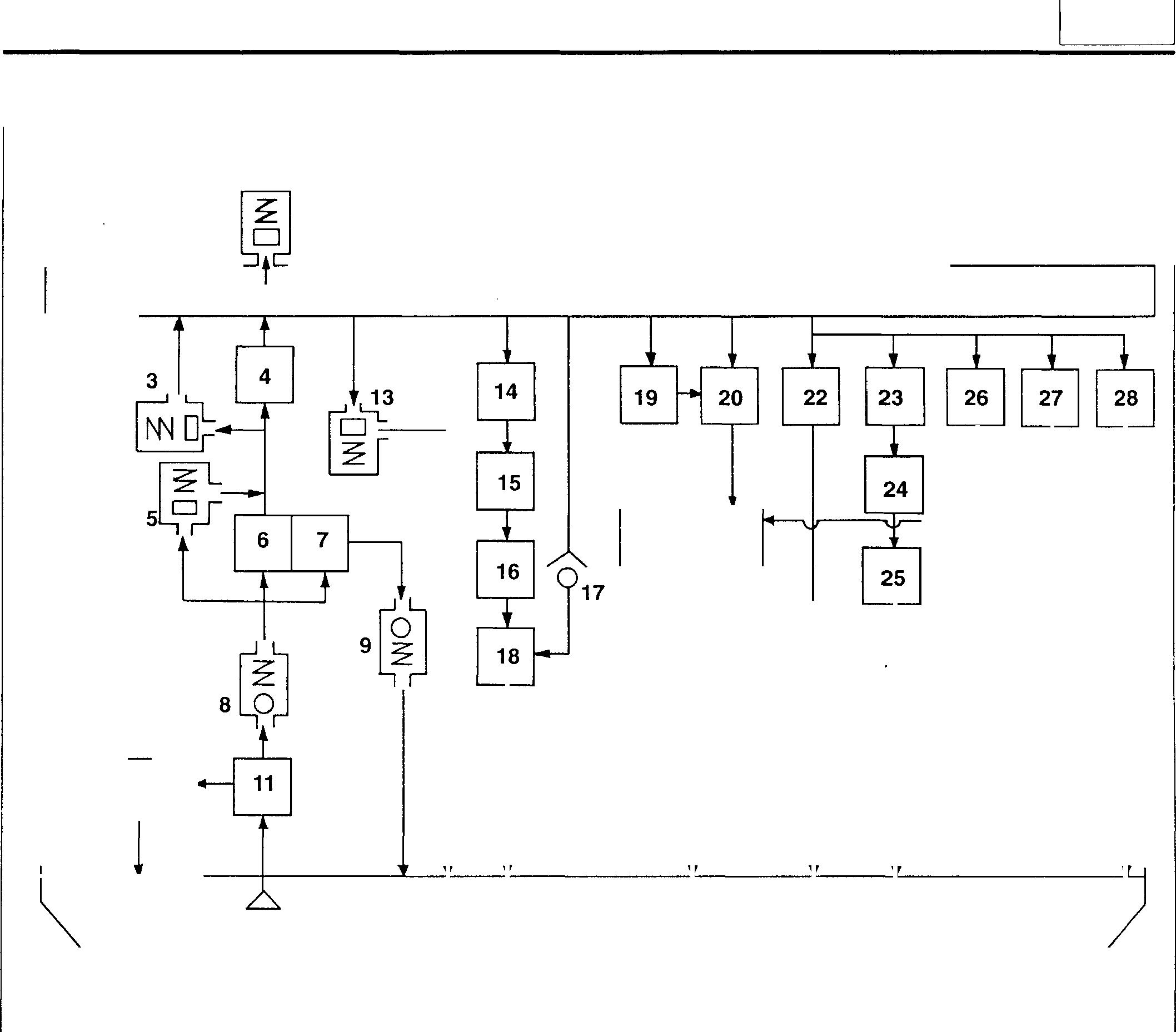
1 Engine oil pressure gauge unit
2 Main oil gallery
3 Bypass valve
4 Oil cooler
5 Engine oil bypass alarm switch
6 Full-flow filter element
7 Bypass filter element
8 Check valve (built into oil filter)
9 Bypass check valve (built into oil filter)
Relief valve (built into oil pump)
Oil pump
Oil strainer
Lubrication System (Oil Flow) 1 2 10 ��� 29 12
10
11
12
13 Regulator valve 14 Crankshaft main bearing 15 Connecting rod bearing 21 16 Connecting rod bushing 17 Check valve for oil jet 18 Piston 19 Injection pump 20 Air compressor (or injection pump drive) 21 Timing gears 22 Camshaft bushing 23 Rocker bushing 24 Push rod 25 Tappet 26 Idler gear shaft No. 1 27 Idler gear shaft No. 2 28 Turbocharger <6D14-T, 15-T, 16-T, 16-TL> 29 Oil pan 12 16887 12-3
STRUCTURE AND OPERATION
Oil Pump
2 01476
1 Crankshaftgear
2 Oil pumpgear
3 Oil pump
4 Oil strainer
5 Reliefvalve
A:Tooil filter
B: From oil pan
C:To oil pan
Oilpump3 isageartype. Itisdrivenbyrotationofthecrankshaft via crankshaft gear 1 andoil pump gear 2.
Relief valve 5 is fitted to the oil pump. When the oil pump discharge pressure exceeds a specified level, the relief valve returns some of the engine oil to the oil pan, thus protecting the lubrication system from excessive oil pressure.
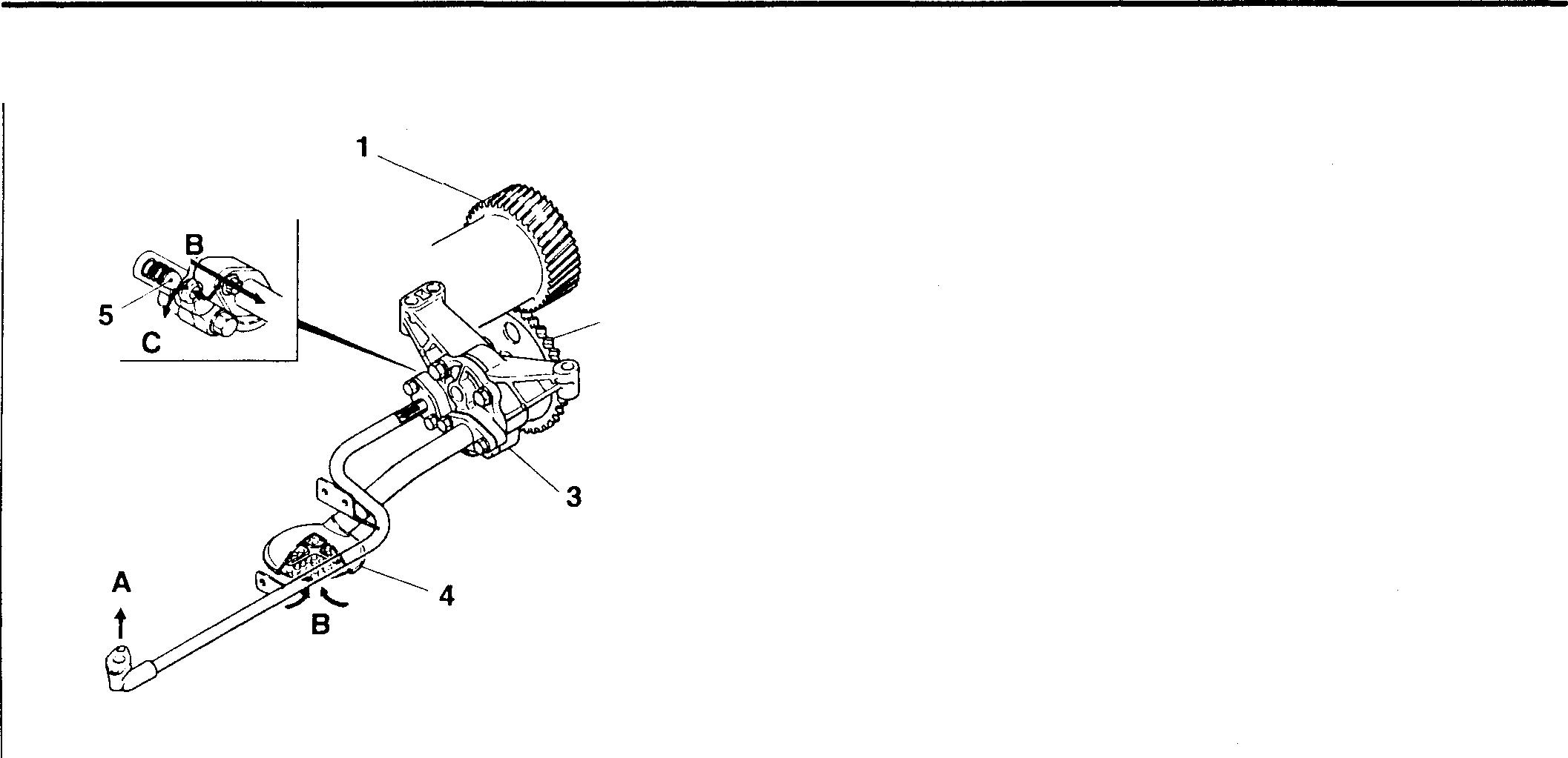
Oil Filter
<Spin-on type>

2
1 Full-flow filterelement
2 Bypass filterelement
3 Engine oil bypass alarm switch
4 Checkvalve
5 Bypasscheckvalve
A:To oil cooler
B: From oil pump
C:To oil pan
Thisoilfilterisaspin-onpaper-filtertype incorporatingfull-flow filter element 1 and bypass filter element 2.
Engineoilbypassalarmswitch3 isfittedtotheoilfilterbracket.
If clogging causesthepressuredifference before andafterthe element to exceed a specified level, a valve inside the switch opens to allow oil toflow directly to the oil cooler.
Checkvalve4isfittedtotheinletto prevent a reverseflowofoil outofthefilterwhentheengineisstationary Inconjunctionwith this, bypass checkvalve 5 opens only when oil pressure inthe bypass arrangement exceedsa specified level. Asaresult, the oil level in the filter iskept constant and oil reaches all partsof the lubrication system quickly when the engine is started.
12-4
·ff!/
01477
<Replaceable-element type> 4
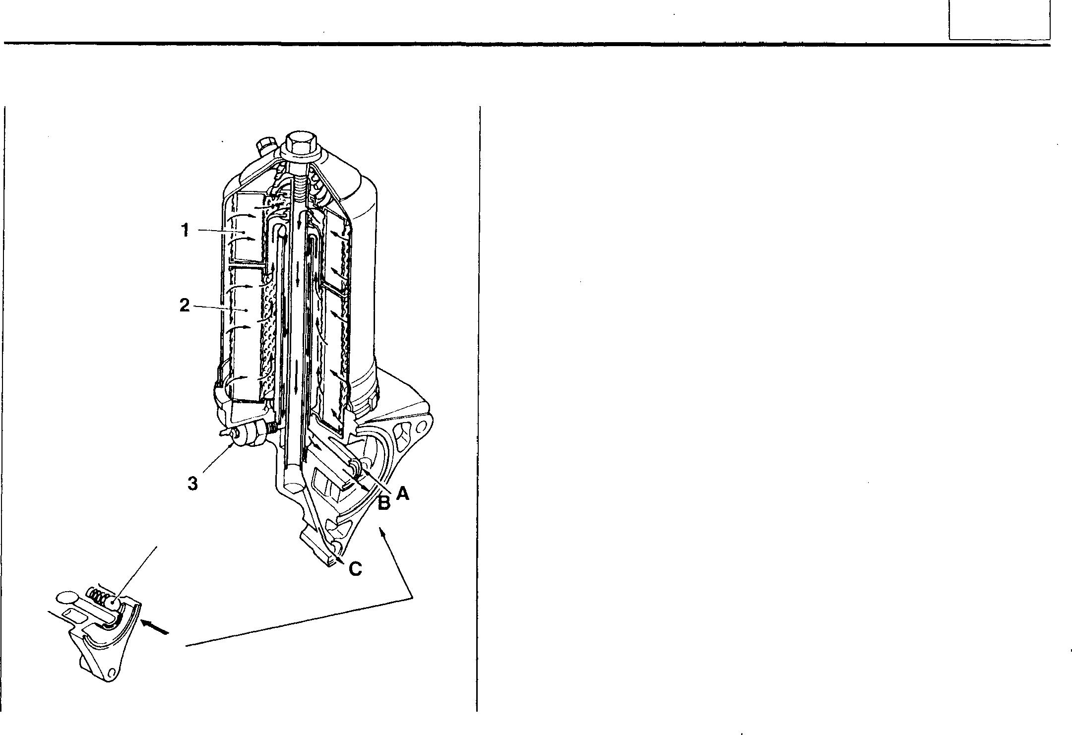
Oil Cooler
1 Full-flow filterelement
2 Bypass filter element
3 Engineoilbypassalarm switch
4 Checkvalve
A:Fromoilpump
B:Tooil cooler
C: Tooilpan
Thisoilfilterisaspin-on paper-filtertypeincorporatingfull-flow filterelement 1 andbypass filter element 2.
Engineoilbypassalarmswitch3isfittedtotheoilfilterbracket. Ifcloggingcausesthepressuredifferencebeforeandafter the element to exceed a specified level, a valve inside the switch openstoallowoil toflowdirectly totheoilcooler.
Checkvalve4isfittedtotheinlettopreventareverseflowofoil outofthefilterwhentheengineis stationary. Thisensuresthat theoillevel in thefilter remains constant suchthatoil reaches all parts of the lubrication system quickly when the engine is started.
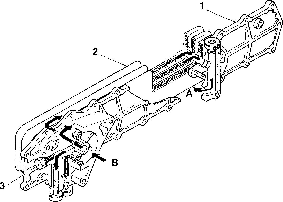
01478
1 Oilcooler cover
2 Oilcooler element
3 Bypass valve
A:Tomainoil gallery
B: From oilfilter
04342
12
12-5
STRUCTURE AND OPERATION
• Bypass valve
When oil viscosity is high at low temperatures or the element is clogged, flow resistance increases. When this happens, bypass valve 3 opens to allow engine oil to return to the main oil gallery without passing through the cooler.
A: To main oil gallery
B: From oil filter
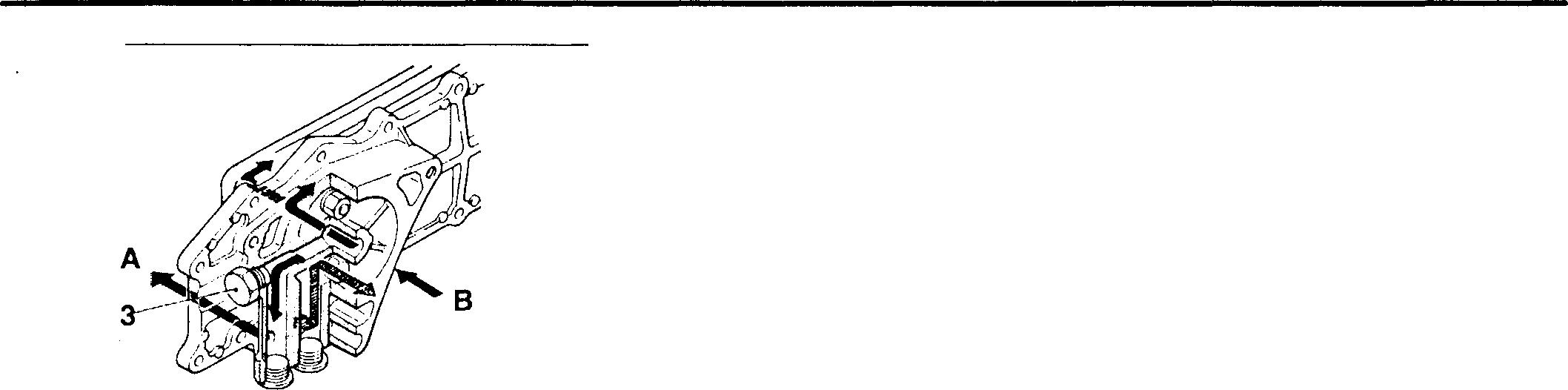
Lubrication of Related Parts
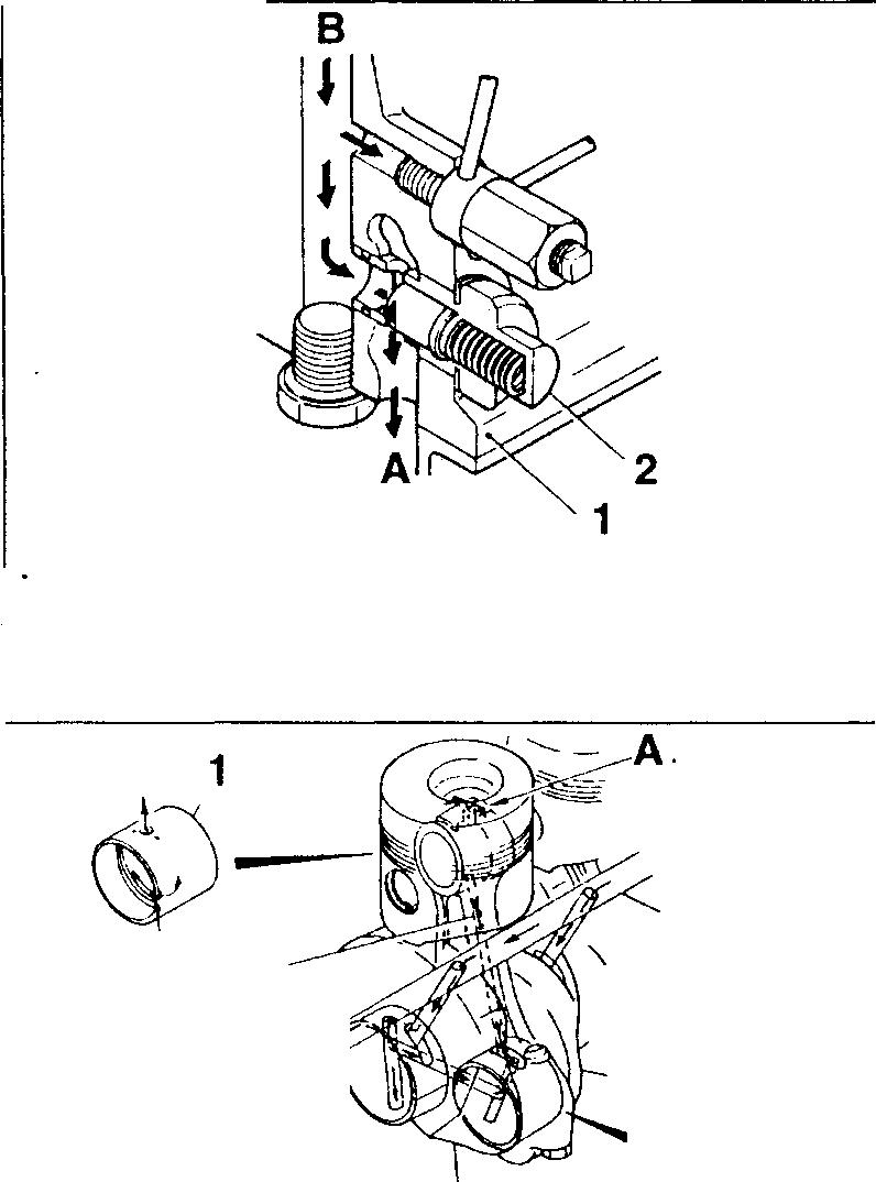
1 Crankcase
2 Regulator valve
A:To oil pan
B: Main oil gallery
• Regulator valve
Whenthe pressure of oil going to main oil gallery B drops below a specified level, regulatorvalve 2 opens, allowing someof theoil to return to oil pan A. The oil pressure is thus constantly regulated.
Engineoil fed tothe main oil gallery lubricates the following related parts:
• Main Bearing and Connecting Rod Bearing
1 Connecting rod bushing
2 Connecting rod bearing
3 Crankshaft
4 Main bearing
A:Oiljet
B: Connecting rod oil passage
C: Main oil gallery
Oil supplied via the oil passage in crankshaft 3 flows through connecting rodoilpassage Bto lubricate theconnectingrod'ssmallend. Theoilthen sprays out of oil jet A at the top of the connecting rod to cool the piston.
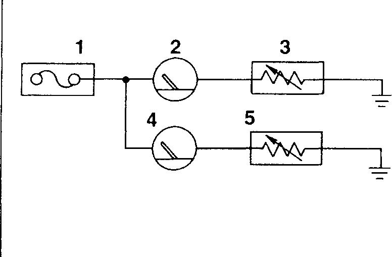
• Oilpressure gauge/temperaturegauge circuit
1 Fuse box
2 Oil pressure gauge
3 Engine oil pressure gauge unit
4 Oil temperature gauge
5 Engine oil temperature sensor
01479
Regulator Valve 16888
C B \� 3 2 (� �01481
16890 12-6
Lubrication System Electric Circuit
• Timing gear and camshaft
1 Camshaftbushing No. 4
2 Camshaft
3 Idlergear No. 2
4 Idlergearbushing
5 Idlershaft No. 2
6 Idlergear No. 1
7 Idlergearbushing
8 Idlergear shaft No. 1
A: Torockerbushing
B: Frommain oilgallery
Engineoilflowsthroughtheinsideofcamshaft2andlubricateseachcamshaft bushing.

01482
<With flywheel PTO>
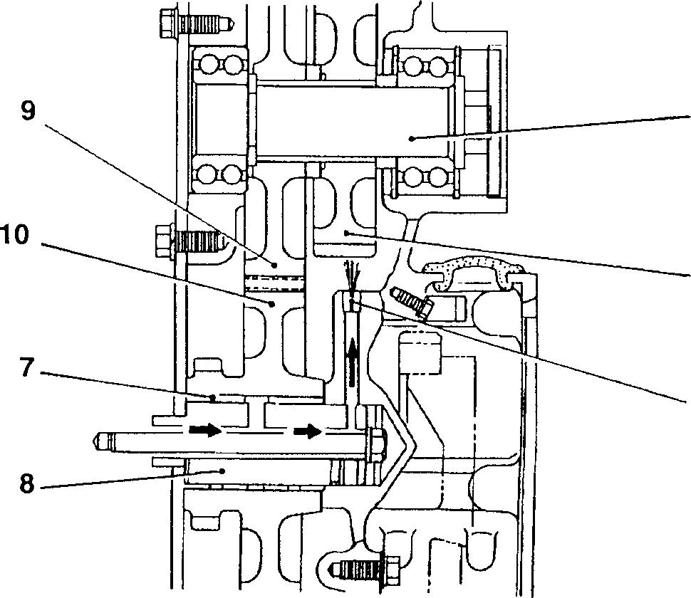
If a flywheel power take-off (PTO) is fitted, oil flows through an oil passage in the flywheel housingandspraysoutoftheoiljettolubricate PTO idlergear B 12.
9 PTO idlergearA
10 Idler No. 1
11 PTOidler shaft
12 PTO idler gear B
13 Oiljet
1
12
11 12 13 16889
12-7
STRUCTURE AND OPERATION
• Valve mechanism
1 Rocker shaft bracket
2 Rocker
3 Rocker shaft
4 Rocker bushing
5 Crankcase
6 Cylinder head
7 Cylinder head bolt
8 Push rod
9 Tappet
10 Camshaft
A: From camshaft bushing No. 4
B: Oil reservoir
C: To oil pan
After lubricatingrocker 2, thecamshaftbushings, andother components, oil enters oil reservoir B to lubricate the cams.
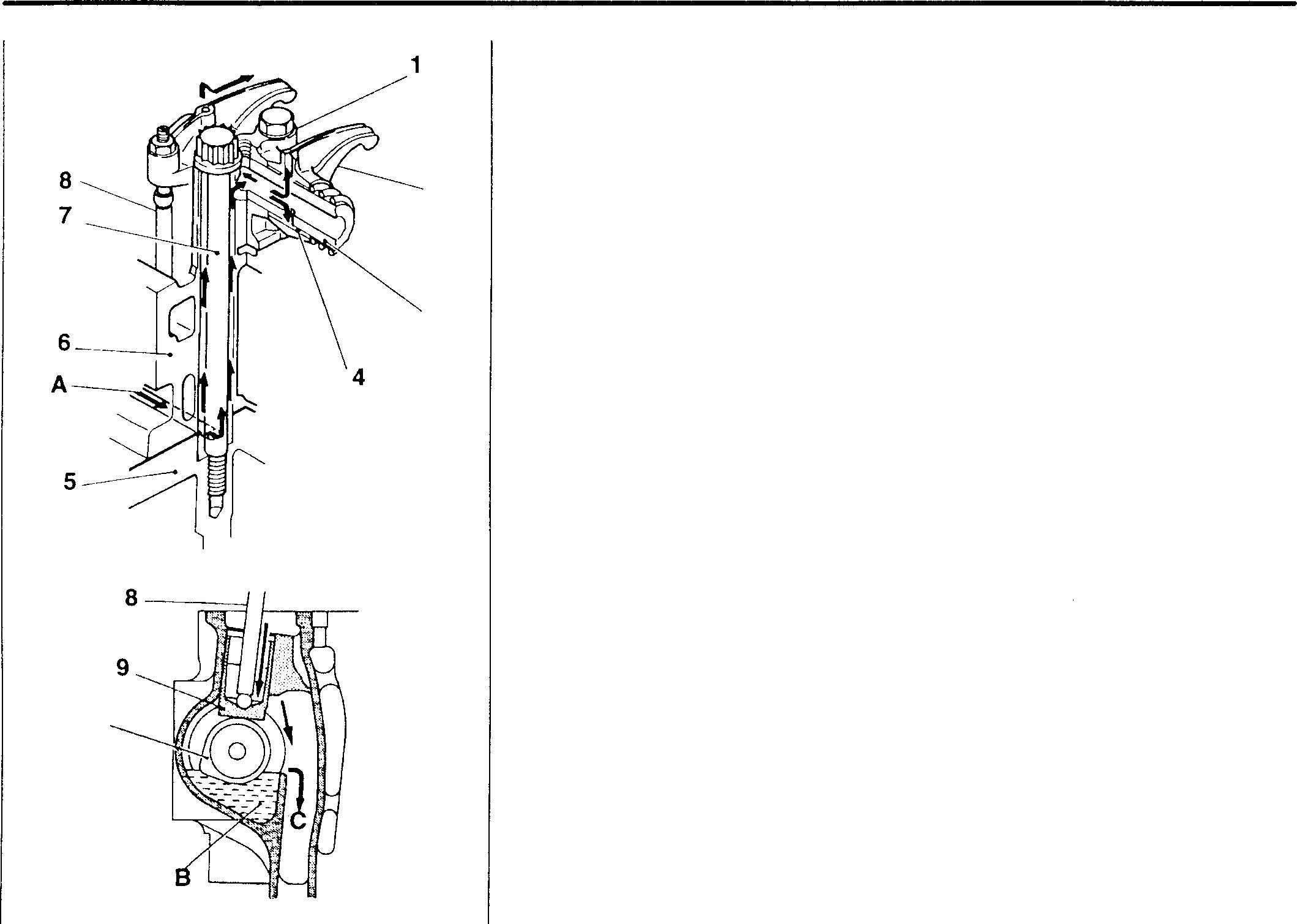
Mitsubishi 6D16-TLEA
• Check valve and oil jet
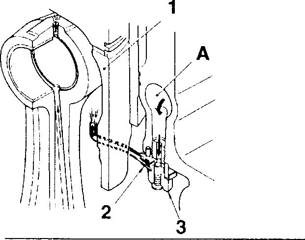
1 Piston
2 Oil jet
3 Check valve
A: Main oil gallery
Anoiljet2isfittedinthelowerpartofthemainoilgalleryAforeachpiston. These oil jets cool the pistons 1 by injecting oil into them. Each oil jet is fitted with a check valve that opens and closes at specified oil pressure levels. At low engine speeds, these check valves 3 close to maintain the required volume of oil in the lubrication system and prevent reductions in oil pressure.
Mitsubishi 6D16TLEA engine parts contact:
email: engineparts2@gmail.com
Phone: 269 673 1638
Text: 269 760 8652
2 3
10
01484
01485
12-8
01487
• Turbocharger
• Bearing housing
2 Snap ring
3 Piston ring
4 Bearing
A: From main oil gallery
8: To oil pan
Via an oil pipe, engineoilis delivered from the mainoil gallery tothe bearing housing 1 to lubricate the inside of the bearing housing. At each end of the turbine wheel shaft, piston ring 3 acts as an oil seal.
• Injection pump
1 Injection pump
2 Governor
3 Air compressor (or injection pump drive)
A: From main oil gallery
8: To oil pan
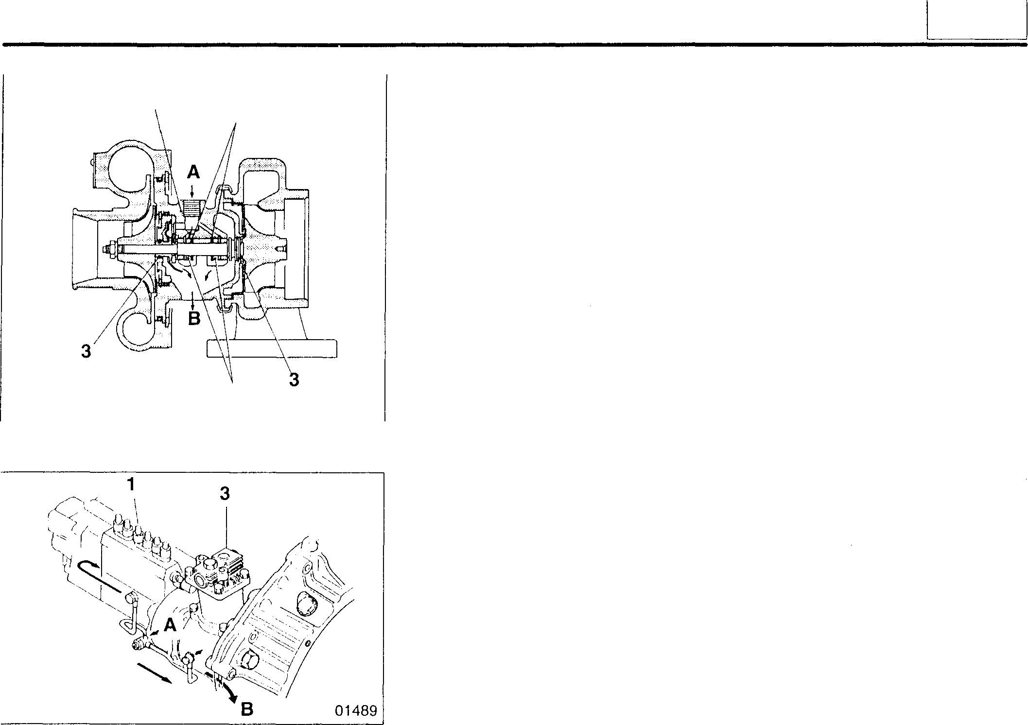
Engine oil that has lubricated injection pump 1 and governor 2 returns to the oil pan via the timer case, air compressor 3 (or injection pump drive), and timing gear train.
• Air compressor
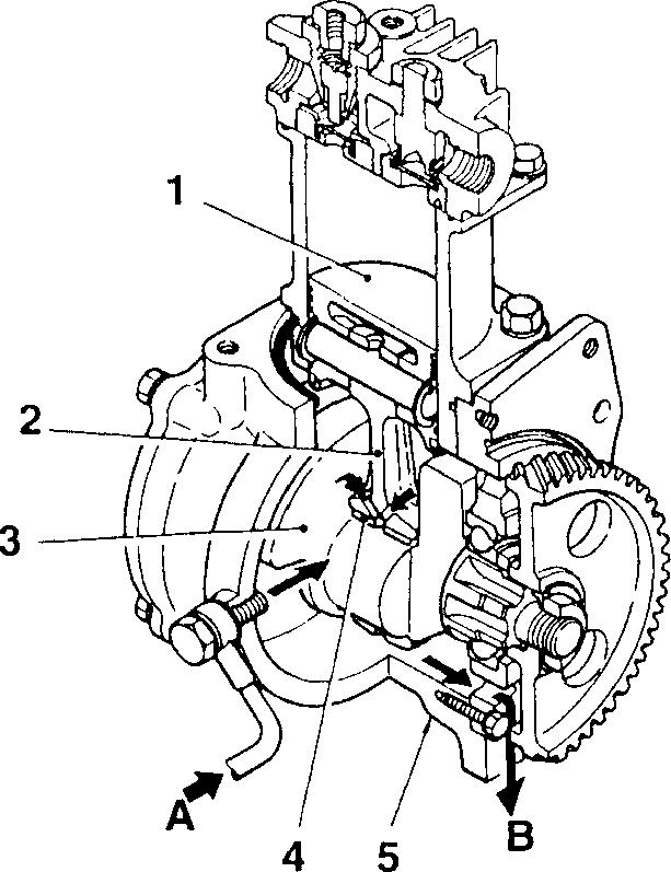
1 Piston
2 Connecting rod
3 Crankshaft
4 Connecting rod bushing
5 Crankcase
A: From main oil gallery
8: To oil pan
Engine oil from the main oil gallery splashes onto connecting rod 2 and lubricates connecting rod bushing 4. Piston 1 and the connecting rod's small end are lubricated by oil that is splashed onto them by the rotation of the crankshaft 3.
1 2 4 01488 2 11107
12
12-9
STRUCTURE AND OPERATION
• Vacuum pump
Someoftheoilused tolubricatethe camshaftbushings is fed tothevacuum pump housing via a flexible hose. After lubricating the vacuum pump vanes, thisoilleavesviaanoutletatthebottomofthe housingand returns to the oil pan.
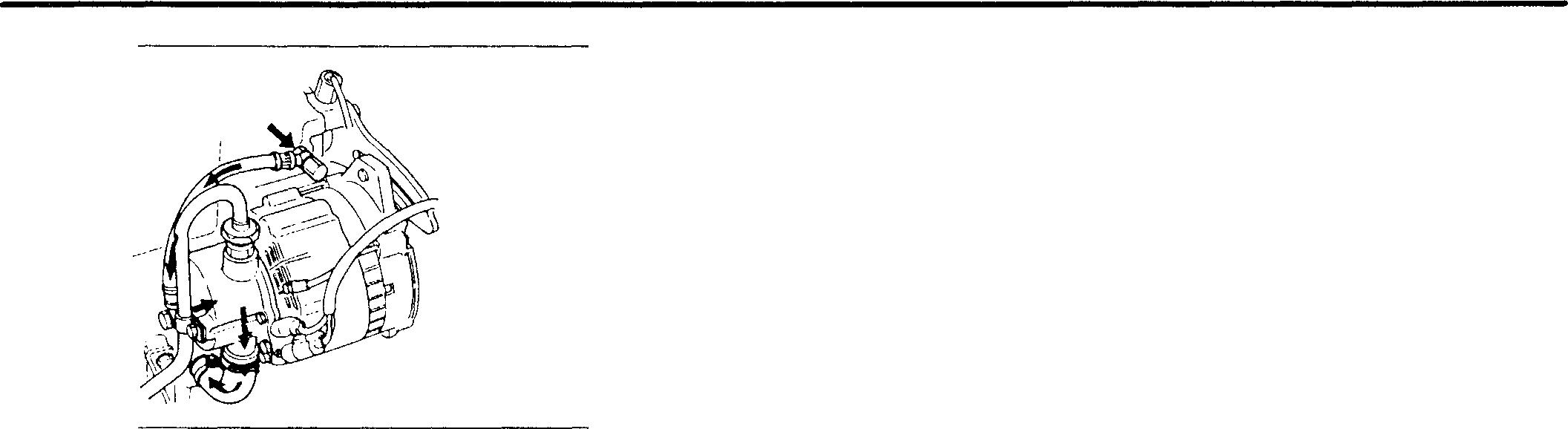
12-10
01491
TROUBLESHOOTING

Mitsubishi 6D16TLEA engine parts contact:
email: engineparts2@gmail.com
Phone: 269 673 1638
Text: 269 760 8652
12 Symptoms C1l C1l :§, .Q Remarks t:'. � 0 ::::, OJ (J) 5 .... C: (I) C1l � .... a. > (I) (I) ·o w C ..c Cl) ·o, (I) :;:: > 0 Possible causes w 0 ....J w Oil cooler elementinstalled poorly 0 0 0 Gasket defective 0 0 0 Oil cooler O-ring defective 0 0 0 Oil coolerelementclogged 0 0 Oilcooler element damaged 0 0 0 Fatiguein bypass valvespring 0 Oil pump malfunctioning 0 0 Interference between oil pump gear and oilpump caseor 0 0 cover Oil pump Oilpipepoorly fitted 0 0 Oil strainer clogged 0 0 Fatigue in relief valvespring 0 Oil filter fitted poorly 0 Oil filter Elementclogged 0 0 Fatigueincheck valve andbypass check valvesprings 0 O-ring defective 0 Front cover assem- Frontoil seal defective 0 COGr11 bly timinggear case Frontcover assemblyfittedpoorly 0 ClJGr11 Rear oil seal defective 0 CDGr11 Flywheel housing Gasket fitted poorly 0 OJGr11 Fatiguein regulator valve spring 0 Piston cooling oiljet(s) defective 0 Oil workingits
up intocombustion chamber(s) 0 CDGr11 Oil working its
down intocombustionchamber(s) 0 lJJGr11 Oil viscosity too high 0 Unsuitableoil quality 0 Deterioration in oil 0 Fuelmixed with oil 0 12-11
way
way
ON-VEHICLE INSPECTION AND ADJUSTMENT
Oil Filter Replacement
<Spin-on type>
O
Tightening torques
Location Parts to be tightened
Tightening torque
Unit: N · m {kgf· m}
Remarks
1 Oil filter drain valve <Upward-facing type> 30 ± 4.9 (3 ± 0.5} -
� Special tools
Location Tool name and shape
3 Oil filter wrench
<Upward-facing type> 3
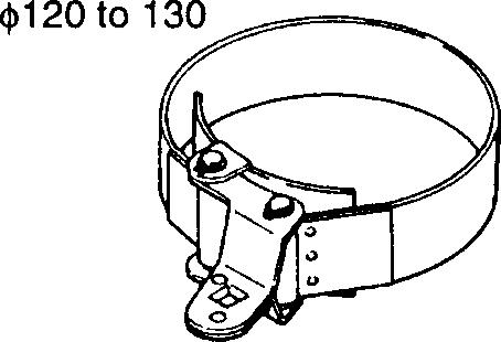
01503
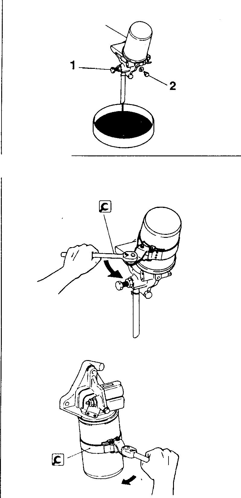
<Upward-facing type>
<Downward-facing type>
Unit: mm
Part No. Application MH061537
WARNING&_-
• Wipe up any spilled engine oil since it can cause a fire.
• Do not touch oil when the engine is hot since it can inflict severe burns.
CAUTION&_-------------
When pouringoil into theengine, take care not to spill any on the V-belts. ContactwithoilcouldmaketheV-beltsslip,renderingthe cooling system less effective.
With an upward-facing oil filter, loosen drain plug 1 and air plug 2 in that order, then drain the oil out of filter 3.
[Removal]
16766
12-12 13311 11601
Oil filter removal
<Upward-facing type>
<Downward-facing type> A 16767
[Installation]
• Clean thesurface on oil filter head 4 that makes contact with oil filter 3.
• Apply afilm of engine oil to gasket area A of filter 3.
• Screwoilfilter 3 intooilfilterhead 4 untilgasketarea A touchestheoil filterhead.
• Tighten filter 3 by afurther 1 1/8 to 1 3/a of aturn.
• Fit oilfilterdrain valve 1.
• Start the engine andcheck that no oil leaks from gasket area A.
• Check theengine oil level and add oil if necessary.
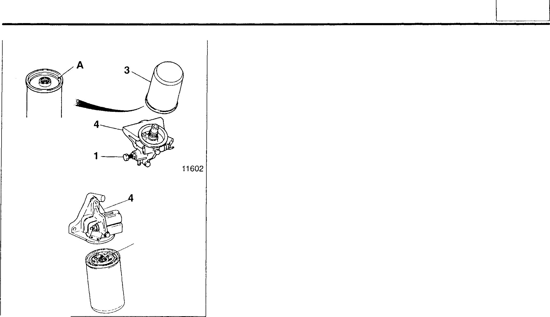
12
12-13
ON-VEHICLE INSPECTION AND ADJUSTMENT
<Replaceable-element type>
0
Tightening torques
Location Parts to be tightened
1 Oil filter drain valve
4 Center bolt
Unit:
Tightening torque Remarks
29 ± 4.9 (3.0 ± 0.5} -
54 ± 4.9 (5.5 ± 0.5} -
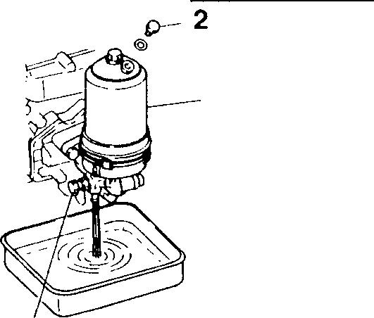
3
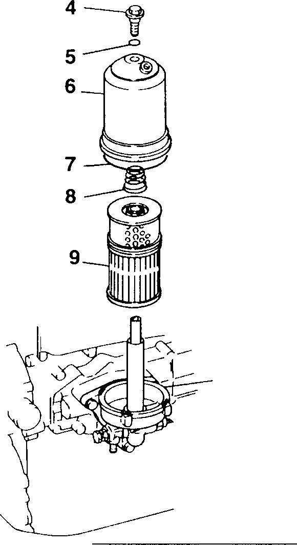
WARNING&
• Wipe up any spilled engine oil since it can cause a fire.
• Do not touch oil when the engine is hot since it can inflict severe burns.
CAUTION&--------------
When pouring oil into the engine, take care not to spill any on the V-belts. ContactwithoilcouldmaketheV-beltsslip, renderingthe cooling system less effective.
With a downward-facing oil filter, loosen drain valve plug 1 and air plug 2 in that order, then drain the oil out of filter 3.
[Removal]
4 Center bolt
5 0-ring
6 Filter case
7 0-ring
8 Set spring
9 Element
10 Filter btacket
[Installation]
Wash all components other than the element in cleaning solvent, then fit the filter in the opposite order from that in which it was removed.
CAUTION&--------------
• If O-ring 7 is twisted when fitted, it may be severed.
• Element 9 cannot be washed and reused.
10
12-14
1 16768
16769
· m}
N · m {kgf
Engine Oil Replacement
0 Tightening torques
Unit: N ·m {kgf · m}
Location Parts to be tightened Tightening torque Remarks
2 . Oil pandrainplug 7 -
3 Oil filterdrainvalve 30 ± 4.9 (3 ± 0.5} -
� Lubricants
Location Points of application Kinds Quantity
- Oil pan dm3 {L}
- Oil filterdm3 {L}
<Upward-facing spin-on type>
1
Generalpowerapplications Non-turbochargedengines: API CC orabove Approx. Turbochargedengines: API CD orabove 9.5 (9.5}
Construction machinery ap-
plications
Spin-ontype Non-turbochargedengines: API CC orabove
Replaceable-elementtype
Turbocharged engines: API CD or above
(2.1}
(2.3}
WARNING,&-------------
• Wipe up any spilled engine oil since it can cause a fire.
• Do not touch oil when the engine is hot since it can inflict severe burns.
CAUTION,&--------------
When pouringoil into theengine, take care notto spill any on the V-belts. Contactwithoilcouldmakethe V-beltsslip, rendering the cooling system less effective.
<Downward-facing spin-on type>
1
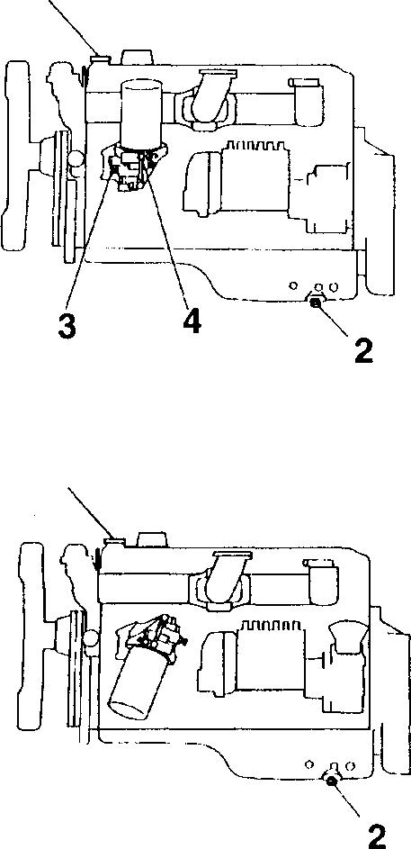
<Replaceable-element type>
1
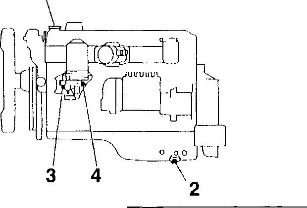
[Draining]
• Warm up the engine, then remove oil filler cap 1.
• Removeoilpandrainplug2, oilfilter drainvalve3, andairplug4.Then, drain the engine oil.
[Filling]
Tighten oil pan drain plug 2 and oil filter drain valve 3 to their specified torques, then pour the specified quantity of engine oil into the engine. 12-15
12
Approx.
16 (16}
2.1
Approx.
Approx. 16770 16771 16772
2.3
ON-VEHICLE INSPECTION AND ADJUSTMENT
Oil Pressure Measurement
Service standards
Location Maintenance item
- Oil pressure (at At no-load minimum speed
Standard value
Unit: MPa {kgf/cm2}
Limit Remedy
0.1 (1.0} orhigher Up to 0.1 Adjust oil temperature (1.0} 70 to 90°C) At no-load maximum speed
0.2 to 0.6 (2.0 to 6.1} Up to 0.2 (2.0}
0 Tightening torque
Location Parts to be tightened
Unit: N ·m {kgf·m}
Tightening torque Remarks
1 Engine oil pressure gauge unit 15 to 22 (1.5 to 2.2)
� Sealant
Location
1
Points of application
Wrap around thread ofengine oil pressure gauge unit
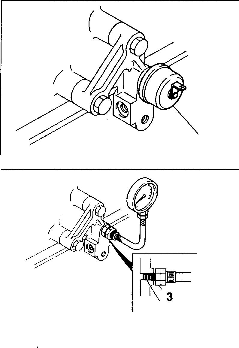
Check with engine cold
Kinds Quantity
Teflon tape 31/2 turns 1 16773 PT1/8 16774
• Remove engine oil pressure gauge unit 1.
• Fit adapter 3 onto the engine oil pressure gauge unit mounting, then fit the oil pressure gauge onto the adapter.
• Warm up the engine until the oil temperature reaches 70 to 90°C.
• Measure the oil pressure at no-load minimum speed and at no-load maximumspeed. Ifthe measured valuesarebelow the specifiedstandard values, overhaul the lubrication system.
• After taking measurements, fit oil pressure gauge unit 1 and tighten it to the specified torque.
NOTE
Oil pressure gauge unit 1 must be fitted with the engine cold.
12-16

I 12 I MEMO 12-17
OIL
PAN, OILJET, AND OIL LEVEL SENSOR
• Disassemblysequence
1 Drain plug
2 Oil pan
3 Engine oil temperature sensor
4 Check valve
5 Oil jet
*: Crankcase [D Gr11
A: Locating pin
0: Non-reusable part
• Assemblysequence
Reverse the orderof disassembly.
CAUTION,&-------
Donottightencheckvalve4inexcessof the specified torque. Excessive tightness can cause defective operation, resultinginscorchingof theengine.
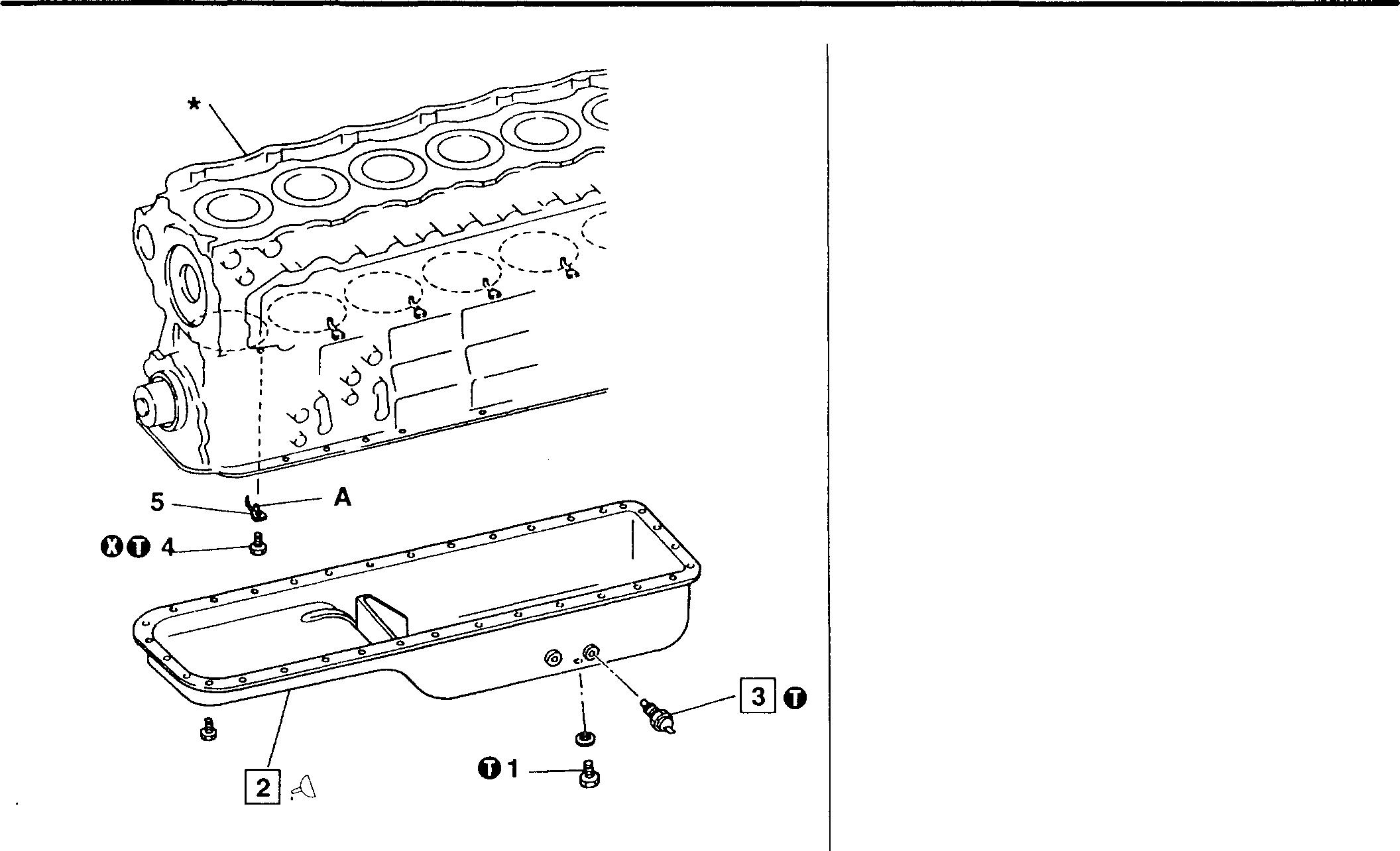
0 Tightening torques
Location Partsto be tightened
1 Drain plug
3 Engineoil temperature sensor
4 Check valve
� Sealant
Location Points of application
2 Crankcasemountingsurfaceofoil pan
Service standards
Figuresin parentheses are approximate.
Mitsubishi 6D16TLEA engine parts contact:
email: engineparts2@gmail.com
Phone: 269 673 1638
Text: 269 760 8652
Unit: N·m {kgf
m}
Location
3 Resistance of engine oil temperature 50°C sensor (between ternimalG) and body) 80°C 100°c
Maintenance item
12-18 16775
·
Tightening torque Remarks 69 {7}34±6.9 {3.5± 0.7}34 {3.5}Kinds Quantity THREEBOND 1207C Asrequired Standardvalue Limit Remedy (136Q) - Replace 48±5 Q27.2±2 QMitsubishi 6D16TLEA Tadano Crane Service Manual
♦ Service procedure
[I] Fitting oilpan
• ApplysealantAtothemountingsurfaceofoilpan2asillustrated. Apply thesealantevenlyand without breaks.
• WithinthreeminutesofapplyingsealantA,fitoilpan2ontothecrankcase*.
CAUTION_&-------------
• Clean the oil pan mounting surface and ensure it is free of oily substancesbefore applying sealant A.
• Carefullymount oilpan2 exactlyinthecorrectposition. Ensure that sealant Adoes not spreadto otherareas.
• Afterfittingoilpan2,waitatleastonehourbeforestartingtheengine.
• ReapplysealantAwhenevertheoilpanmountingboltshavebeen loosened.
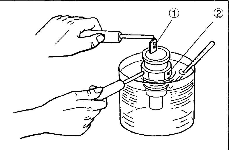
@] Engine oiltemperaturesensor
• Place engine oiltemperaturesensor3 in acontainerofengine oil.
• Heattheengineoiluntilitreacheseachofthetemperaturesintheservice standardstable.
• Ateach of the given temperatures, measure theelectrical resistance betweentheengineoiltemperaturesensor'sterminalCDandbody(2)_
• If the resistance values do not match those in the service standards table, replace theengine oil temperaturesensor3.
Mitsubishi 6D16TLEA engine parts contact: email: engineparts2@gmail.com
Phone: 269 673 1638
Text: 269 760 8652
2 A \ �i 1.5mm 11115
03868
12
12-19
OIL PUMPAND OIL STRAINER
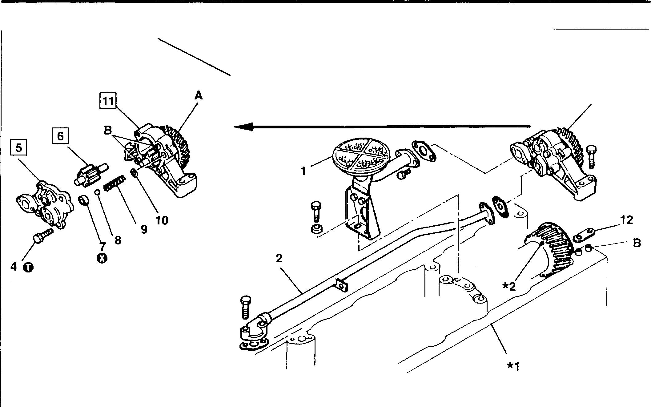
• Inspection before disassembly
CI P.12-21
• Disassembly sequence 1 Oil strainer
Oil pipe
Oil pumpassembly
*1 : Crankcase CI] Gr 11
*2: Crankshaftgear CI] Gr 11
A: Oilpump gear
B: Locating pin
0:Non-reusablepart
01497
• Do not remove parts #7 to 10 unless they are defective.
• Gear and case assembly11 is anintegratedunit and cannot be disassembled. If any defect isapparent, replace the whole unit.
• Do not remove oil strainer 1 and oil pipe 2 from oil pump assembly 3 unless they are defective. Remove those three as a unit.
• Assembly sequence
Reverse the orderofdisassembly.
3
4
5
6 Driven gearassembly 7
NOTE 8 Relief valve 9 Relief valvespring 10 Washer 11 Gearand case assembly 12
2
Bolt
Cover
Ring
Shim
3
12-20
6,11
Replace diameter ofcase andcover
ofcase
8 Relief valveopeningpressure 980to 1175 kPa {1Oto 12kgf/cm2} - Replace
9 Reliefvalve springload (installedlength = 30) 84N {8.6kgf} - Replace *2, A Backlash betweenoilpumpgearandcrankshaft
0.18
Adjustwith gear shims I
0
Tightening torque
4
to betightened
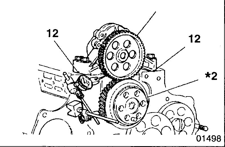
{kgf·m}
torque
25± 4.9{2.5± 0.5} -
♦ Service procedure
• Inspection before disassembly
Measurethe backlash betweenoilpumpgear Aandcrankshaftgear *2. Iftheamountof backlashexceedsthespecified limit, adjustitwithshims 12.
Shim thickness Change in amount of backlash 0.1mm 0.073mm 0.2mm 0.146mm
NOTE
Shim 12musthave the same thickness on the left andrightsides.
5"' EB EB 6
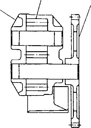
11
W [§] [DJ Inspection of cover, driven gear assembly, and gear and case assembly
Measuretheclearance betweeneachgear shaft andtheinternal diameters of the cover and case
12 Service
Unit: mm Location Maintenanceitem Standard value Limit Remedy (Basic diameter in [ ]) 5, 11 Clearance betweendrivegearshaftandinnerdi- [20] 0.04to 0.07 0.15 Replace
5,
Clearance between
[20]
0.15
6,
Clearance between
0.10to
0.2
Difference between heightof eachgearand depth 0.06to 0.11 0.15
standards
ameter ofcover
driven gearshaftand inner
0.04to 0.07
11
caseandtoothtipsofeach
0.19
Replace gear
0.08to
0.35
Location
Oil
Unit: N ·m
Parts
pumpcovermounting bolt
A
01499 Tightening
Remarks
12-21
OIL PUMPAND OIL STRAINER
[I] G] Inspectionofdrivengearassemblyandofgearandcaseassembly
(1) Differences between gear heights and case depth
Replace any component whose measurement is out of specification.
(2) Clearance between gear teeth and case
Replace any component whose measurement is out of specification.
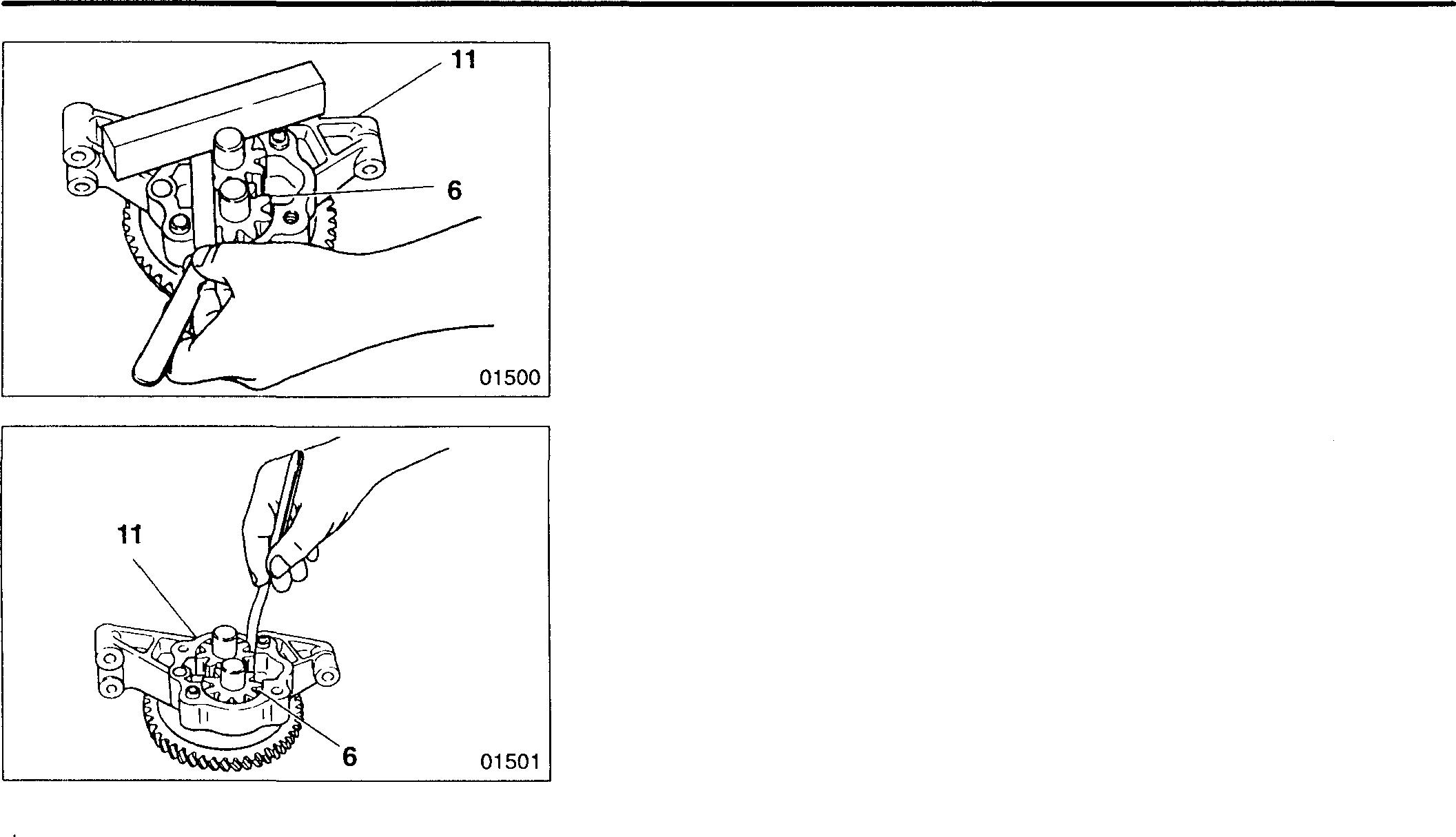
12-22
I 12 I
12-23
MEMO
OIL FILTER
<Spin-on type>
<Upward-facing>
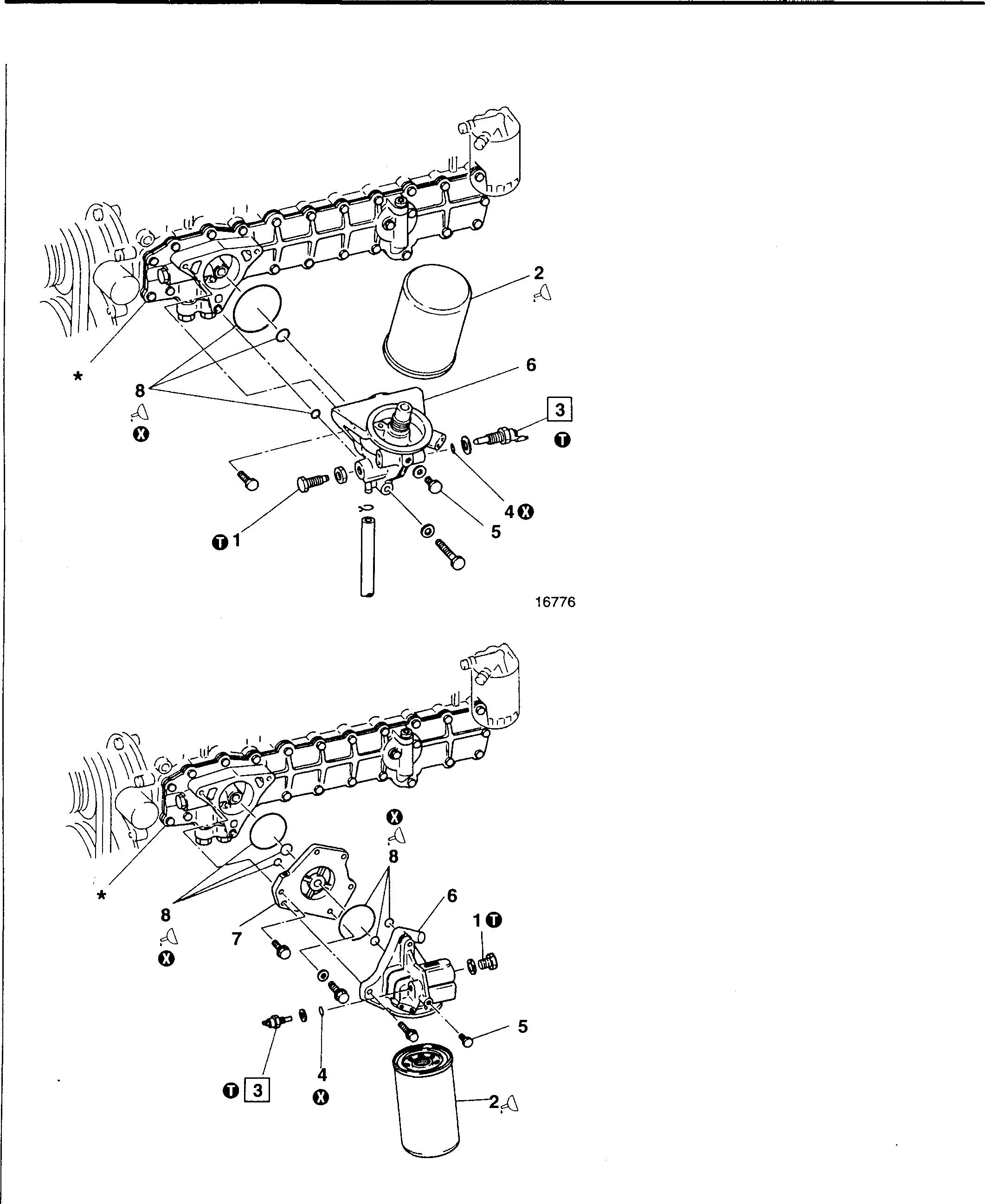
<Downward-facing>
Mitsubishi 6D16TLEA engine parts contact:
email: engineparts2@gmail.com
Phone: 269 673 1638
Text: 269 760 8652
• Disassembly sequence
1 Oil filterdrain plug
2 Oil filterQJ P.12-12
3 Engineoilbypass alarm switch
4 O-ring 5 Airplug
6 Oil filterhead
7 Spacer (downward-facing filteronly)
8 O-ring
*:Oil coolerQJ P.12-28
O:Non-reusable part
• Assembly sequence Reversetheorderof disassembly.
16777 12-24
WARNING&.-------------------------
• Wipe up any spilled engine oil since it can cause a fire.
• Do not touch oil when the engine is hot since it can inflict severe burns.
CAUTIONL'.1,.
Whenpouring oil into the engine,take care not tospill any on the V-belts. Contactwith oil could make the V-belts slip, rendering the cooling system less effective.
Service standards
Location Maintenanceitem Standardvalue Limit Remedy
3 Engineoil bypass alarmswitchvalveopeningpres- o.19jj05 MPa{1.9+065 kgf/cm2} - Replace sure
0
Tightening torques Unit: N·m {kgf·m}
Location Parts to betightened
1 Oilfilter drainvalve
� Lubricant
Location
2 7
±4.9{3.0±0.5}Downward-facing
±2.0{0.8±0.2} -
3 Engineoil bypassalarm switch 49±4.9{5.0±0.5} -
Points ofapplication Kinds
Applythinfilm tooilfiltergasketarea[_[] P.12-12
Applyto O-rings
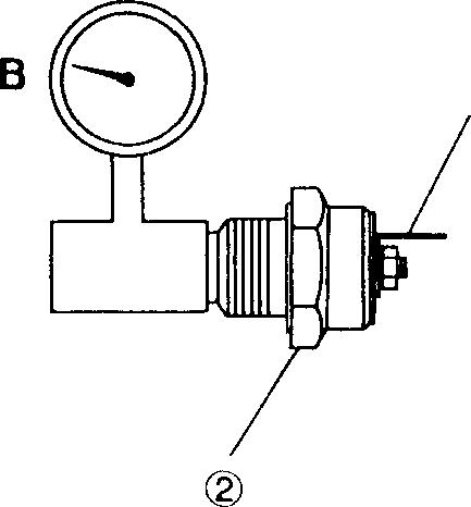
Engineoil Asrequired
Engineoil Asrequired
♦ Service procedure
[]] Inspection of engine oil bypass alarm switch
Carry out the following inspections and replace the engine oil bypass alarmswitch 3 iftheresultsareunsatisfactory:
• With no air pressure A applied to engine oil bypass alarm switch 3, checkthatthereisnoelectricalcontinuitybetweentheterminalCDand body®oftheengineoil bypass alarm switch.
• StartingwithpressureofOkPa{O kgf/cm2}, graduallyincreasetheair pressure A onengineoilbypassalarmswitch 3. Notetheairpressure when electrical continuity appears between the terminalCD and body ®.Verifythatthispressureconformswiththespecifiedstandardvalue.
B:Air pressuregauge
12
Tightening
torque Remarks
30
Upward-facing
7.8
AQ
Quantity
CD 11312
12-25
OIL FILTER
<Replaceable-element type> 5
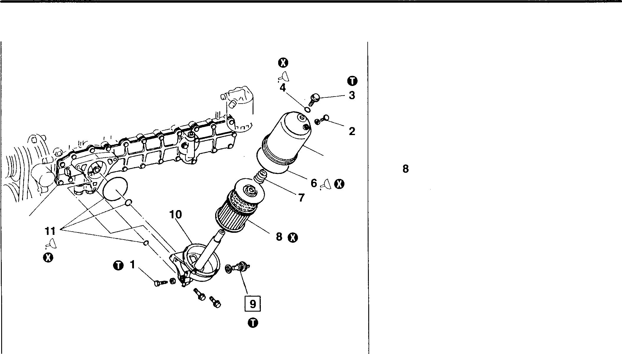
*
• Disassembly sequence
1 Oilfilterdrain valve
2 Airplug
3 Center bolt
4 0-ring
5 Filtercase
6 0-ring
7 Set spring Element
9 Engine oil bypass alarm switch
10 Filterbracket
11 0-ring
*:Oilcooler Q] P.12-28
0: Non-reusablepart
• Assembly sequence
Reverse the orderof disassembly.
WARNING&-------------------------
• Wipe up any spilled engine oil since it can cause a fire.
• Do not touch oil when the engine is hot since it can inflict severe burns.
CAUTION&------------------------
When pouringoilintothe engine,takecarenotto spill anyontheV-belts. ContactwithoilcouldmaketheV-belts slip, rendering the cooling system less effective.
Service standards
Engineoilbypassalarmswitch
torques
to 0-rings
of
Mitsubishi 6D16TLEA engine parts contact: email: engineparts2@gmail.com
Phone: 269 673 1638
Text: 269 760 8652
16778
Location Maintenance item Standard value Limit Remedy 9
openingpres- 145+�O kPa {1.5+�S kgf/cm2} - Replace sure
Tightening
Unit: N·rm {kgf·m} Location Partsto be tightened Tightening torque Remarks 1 Oilfilterdrainvalve 29± 4.9 {3.0± 0.5}3 Centerbolt 54± 4.9 {5.5± 0.5}9
oilbypass alarmswitch 49± 4.9 {5.0± 0.5}�
Location Points
application Kinds Quantity 4, 6, 11 Apply
Engineoil Asrequired 12-26
valve
0
Engine
Lubricant
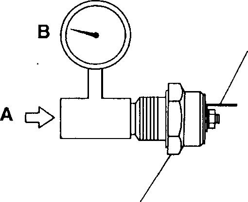
♦ Service procedure
� Inspection of engine oil bypass alarm switch
Carry out the following inspections and replace the engine oil bypass alarm switch 9 if the results are unsatisfactory:
• With no air pressure A applied to engine oil bypass alarm switch 9, check that thereis noelectrical continuity between the terminal(1) and body® of the engine oil bypass alarm switch.
• Starting with pressure of OkPa {O kgf/cm2}, gradually increas� the air pressure A on engineoil bypass alarm switch 9. Note the air pressure when electrical continuity appears between the terminal (1) and body �). Verifythatthispressureconformswiththespecifiedstandardvalue.
B: Air pressure gauge
G) c� 11312 12
12-27
OIL COOLER
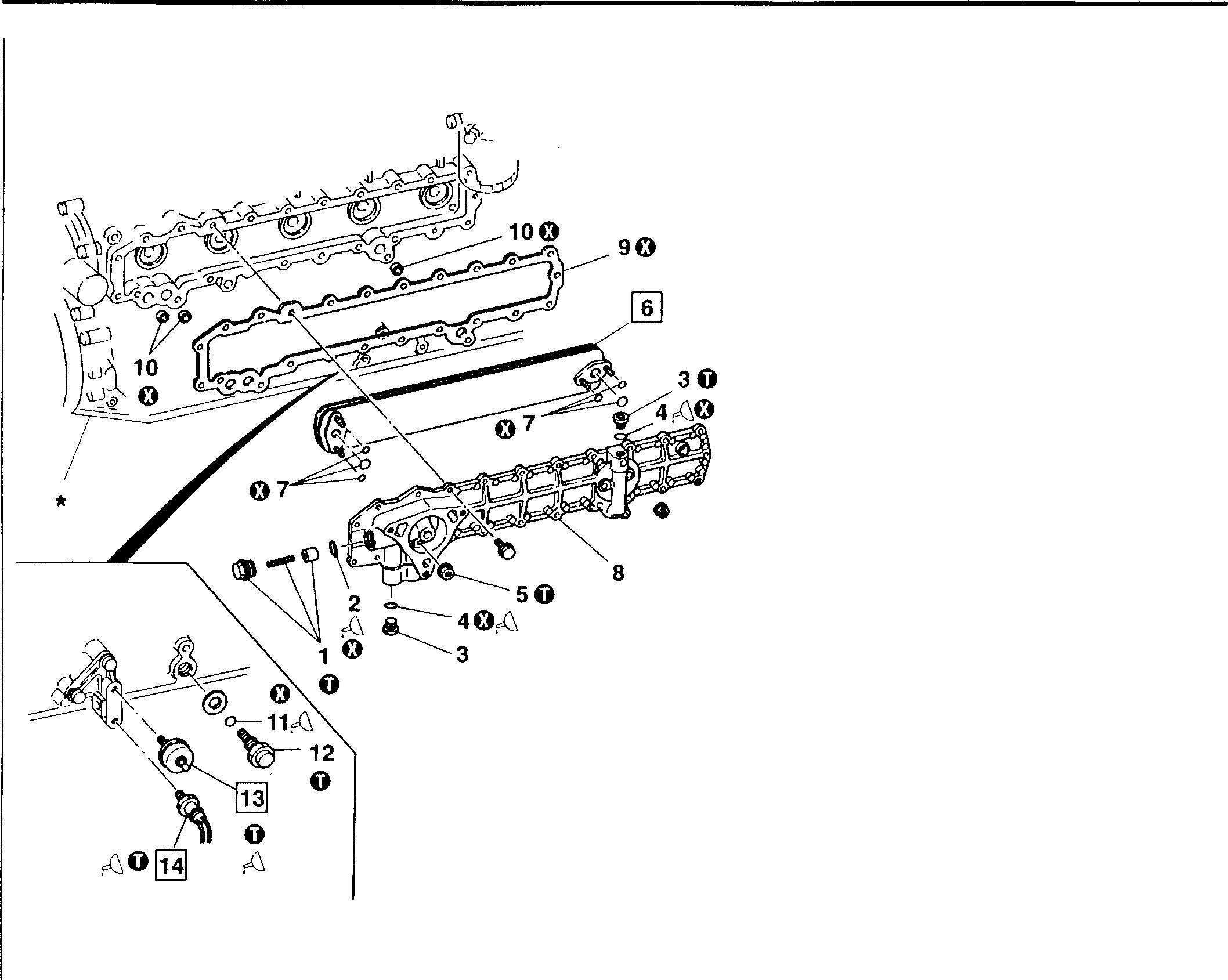
Service standards
Maintenance item
1 Oil cooler bypass valve opening pressure
6 Oil cooler element air leakage (air pressure of 980 kPa {10kgf/cm2 } for 15seconds) 14 Operating pressure of engine oil pressure switch
0 Tightening torques

1 Bypass valve
Parts to be tightened
Oil cooler plug
Nut (oil cooler element mounting)
valve
• Disassemblysequence
1 Bypass valve 2 O-ring
3 Oil cooler plug
O-ring
Nut
Oil cooler element
O-ring
Oil cooler cover
Gasket
O-ring
O-ring
Regulator valve CO P.12-30
Engine oil pressure gauge unit
Engine oil pressure switch
*: Crankcase assembly CO Gr 11 0: Non-reusable part
• Assemblysequence
the order of disassembly.
Location
Locat�on
3
5
12
13 Engine
14 Engine oil
switch 12-28 16779
Regulator
oil pressure gauge unit
pressure
4
5
7
8
9
10
11
12
13
14
6
Reverse
Standard value Limit Remedy 295± 20kPa (3.0± 0.2kg/cm2 } -0cc - Replace 49± 9.8kPa (0.5± 0.1kgf/cm2 } - Replace Unit: N ·m {kgf·m} Tightening torque Remarks 20± 4.9(2.0± 0.5}25± 4.9(2.5± 0.5}20±4.9(2.0± 0.5}105± 9.8(11± 1}15to 22(1.5to 2.2}15to 22{1.5to 2.2}Mitsubishi 6D16TLEA engine parts contact: email: engineparts2@gmail.com Phone: 269 673 1638 Text: 269 760 8652
� Lubricant and sealant
Location
2,4,11
13,14
A Pointsofapplication
Applyto O-rings
Engine oil
Wraparoundthread ofengine oilpressure gauge unitand Teflontape
Kinds
Quantity
As required
1/2 turns engine oilpressure switch 01505
♦ Service procedure
• Cleaning
• Checkwhethercarbondepositsorsludgehaveaccumulatedintheoil passagesofoilcoolerelement6andoilcoolercover8orintheoilcooler'sbypassarrangement. Removeanydepositswithcleaningsealant.
• Cleanoutany waterscaleorfurthathasaccumulatedin theoilcooler element 6 or oil cooler cover 8. OJ Gr 14
[§] Inspection of oil cooler element
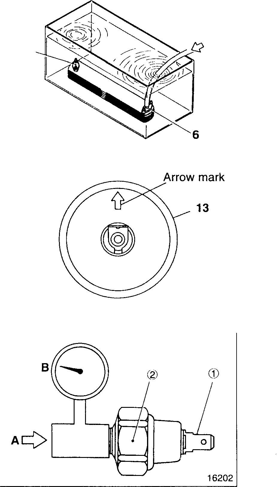
Plug outlet A of oil cooler element 6 and connect a hose to the oil inlet. Then, immerse the oil cooler element inatank of water.
Apply thespecified airpressureviathe hose and check that no airleaks fromthe oil cooler element.
If any air leaks, replace the oil cooler element.
� Engine oil pressure gauge unit
Iftheengineoilpressuregaugeunit 13 isinstalledhorizontally, itmustbe fittedwithits arrowpointingupward.
� Inspection of engine oil pressure switch
Carry out the following inspections and replace the engine oil pressure switch 14 ifthe results are unsatisfactory.
• Withnoairpressureappliedtotheengineoilpressureswitch 14, check that there is continuity between the terminal(1) and body <gl_
• Startingfrom0kPa{0kgf/cm2}, gradually applytheairpressureAand check that the air pressure when the continuity between the terminal (1) and body cg) disappears is withinthespecification.
B: Air pressure gauge
12
16886
3
12-29
REGULATOR VALVE
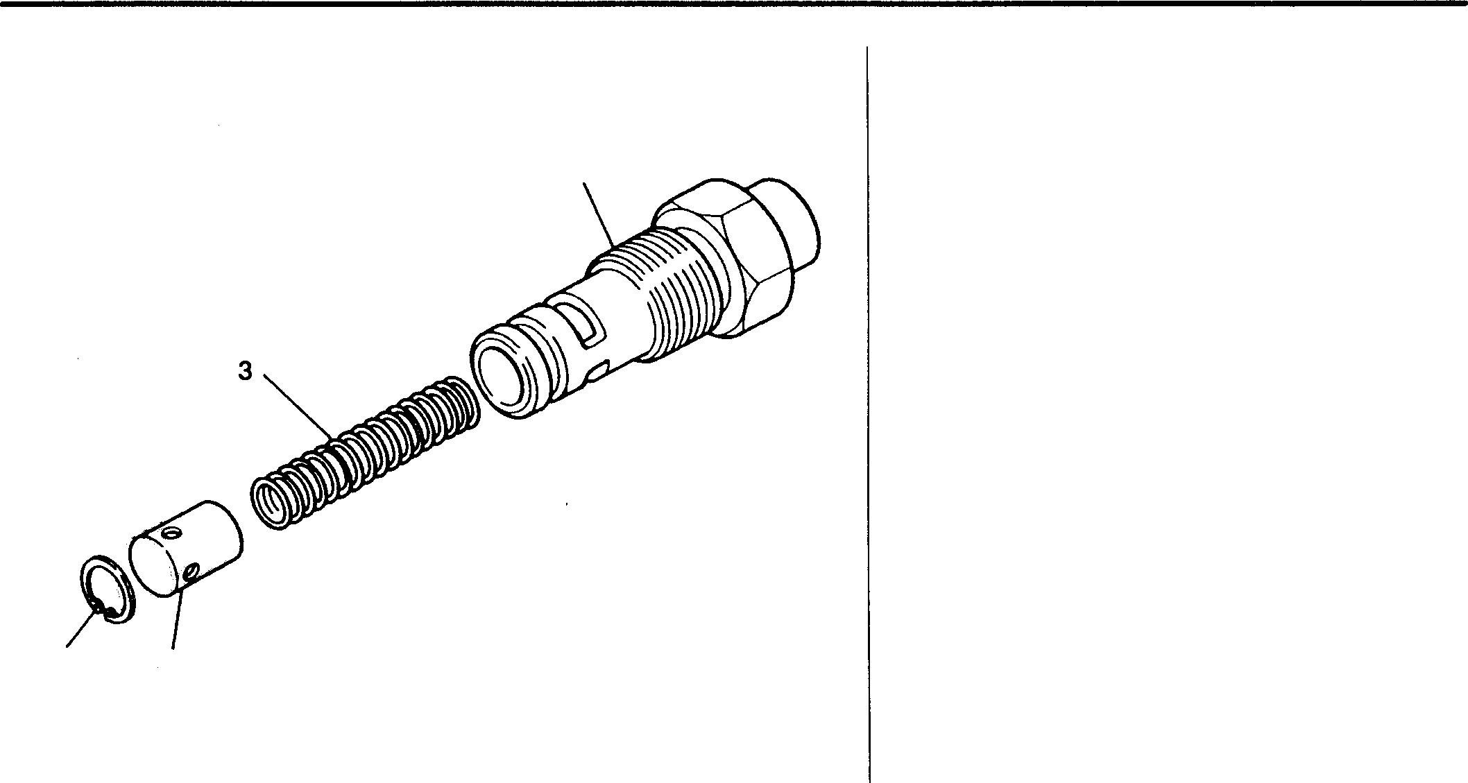
1 2
Service standards
Location Maintenance item
3 Regulator valve spring load (installed length = 48.3 mm)
- Regulator valve opening pressure
4
09189
• Disassembly sequence
1 Snap ring
2 Valve
3 Spring
4 Body
• Assembly sequence
Reverse the order of disassembly.
[Installation] ffi P.12-28
Standard value (Basic diameter in [ ]) 76 to 80 N {7.8 to 8.2 kgf}
390 ± 29 kPa {4.0 ± 0.3 kgf/cm2}
Mitsubishi 6D16TLEA engine parts contact:
email: engineparts2@gmail.com
Phone: 269 673 1638
Text: 269 760 8652
12-30
LimitRemedy-
GROUP 13 FUEL AND
13
CONTROL STRUCTUREANDOPERATION ............................... 4 TROUBLESHOOTING......................................... 16 ON-VEHICLEINSPECTIONAND ADJUSTMENT • Checking andAdjusting InjectionTiming ............................. 20 • Checking andAdjusting Minimum and Maximum No-loadSpeeds ...... 22 • Cleaning Fuel Feed Pump Gauze Filter ....................•.......... 23 FUELFILTER . . . . . . . . . . . . . . . . . . . . . . . . . . . . . . . . . . . . . . . . . . . . . . . . 24 SECONDARYFUELFILTER ................................... 26 WATER SEPARATOR ....................................•.... 27 INJECTIONPUMP ....................................•....... 28 INJECTIONPUMP DRIVE .............................•..•.••. 30 INJECTIONNOZZLE <1-spring Type>.........................................•..•.........• 34 <2-springType: Zexel> ........................................... Deleted <2-spring Type: Nippondenso>.................................... Deleted 13-1 I
ENGINE
Other Items
Fuelfiltertype
Item
Secondaryfuelfiltertype
Waterseparatortype
Specifications
Spin-on type (paperfilter)
Filterpapertype
Sedimenttrap type
13
13-3
STRUCTURE AND OPERATION
Tadano Crane Mitsubishi 6D16TLEA Fuel System
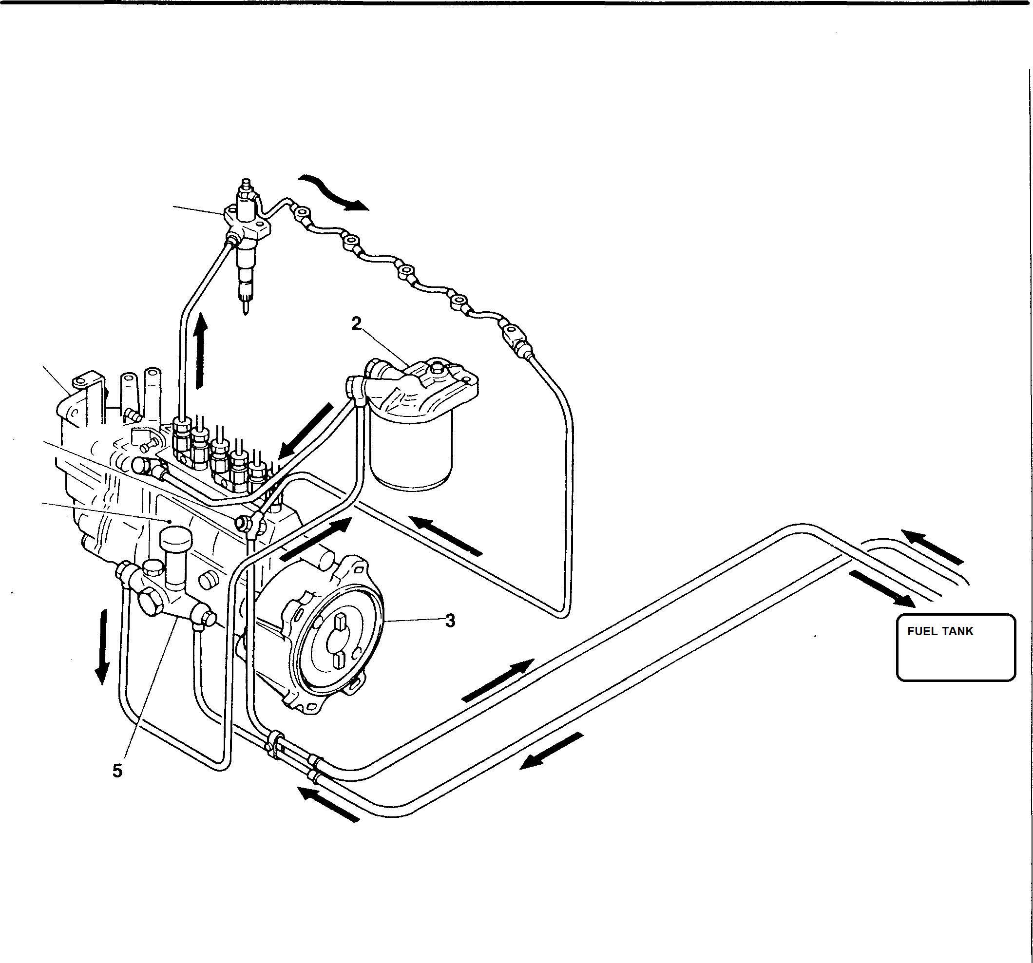
l• Fuel from thefuel tank 4is drawnupby the feed pump 5 andstrainedbythefuelfilter 2. The feedpumpisdrivenbya cam in the injection pump 6.
• Afterfiltration, fuelisfedto theinjectionpump 6. Fromthere, itisfedunderhighpressuretotheinjectionnozzles 1. The injectionnozzles spray the fuelintothecombustionchambers.
• Ifthefuelpressureintheinjectionpump6exceedsapresetlevel,theoverflowvalve7openstoallowexcessfueltoreturn to thefuel tank 4.
Mitsubishi 6D16TLEA engine parts contact: email: engineparts2@gmail.com
Phone: 269 673 1638
Text: 269 760 8652
1 8 7 6 1 Injection nozzle 2 Fuel filter 3 Automatic timer 4 Fuel tank
5 Feed pump 6 Injection pump 7 Overflow valve 8 Governor 4 12574
13-4
Fuel Filter
1 Fuel filter
2 Fuel filter head
A: From feed pump
B: To injection pump
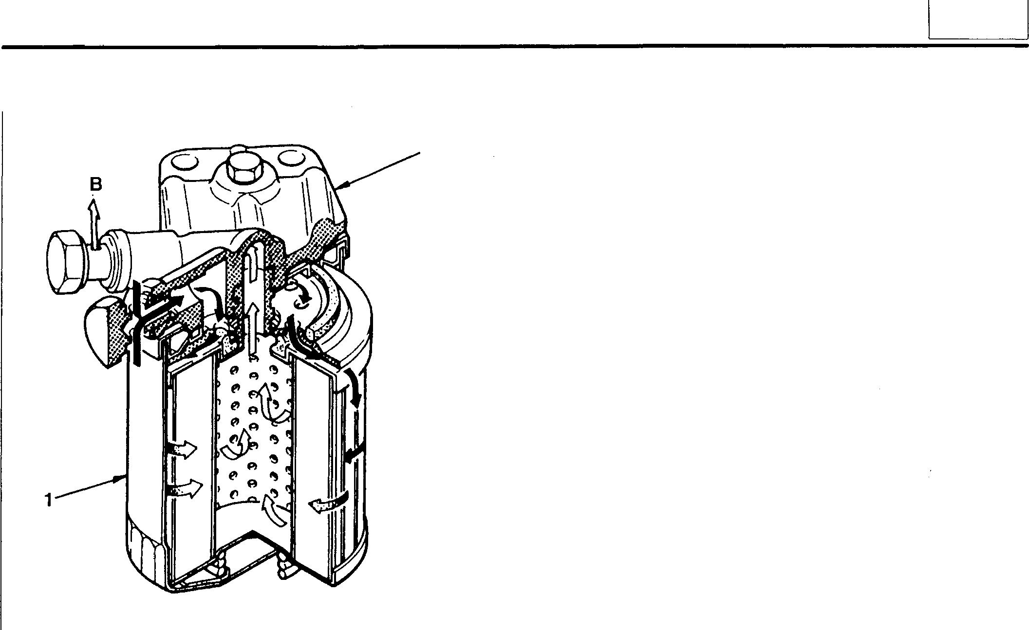
Secondary Fuel Filter
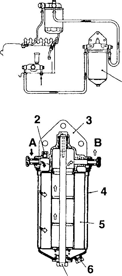
L1
2 01822
The fuel filter separates any water content out of fuel fed from the injection pump's feed pump, and its element removes any impurities.
1 Secondary fuel filter
2 Air plug
3 Cover 4 Case
5 Element
6 Drain plug
7 Center bolt
A: From feed pump
B: To fuel filter
When the engine is run on JIS class 1 heavy oil (ASTM No. 4; BS class D, B1 and B2), a secondary fuel filter is fitted in the positionillustrated. Likethe regular fuelfilter, thisunitseparates any water content out of fuel received from the feed pump. It uses a paper element to remove impurities.
7 18223
13
13-5
STRUCTURE AND OPERATION
Water Separator
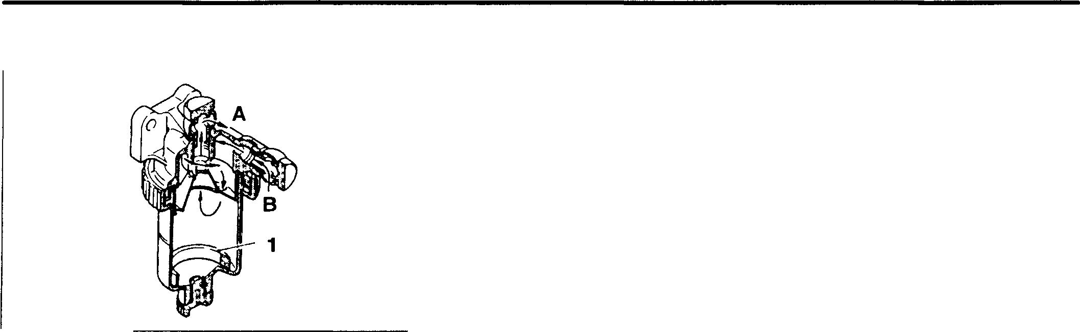
18224
1 Water level ring
A: Fuel outlet (to feed pump)
B:Fuel inlet
Thesedimenttraptypewaterseparatorsplitsfuelandwatercentrifugally utilizingthedifferenceinspecificgravitybetweenthetwofluids. Fuelenteringfromtheinletconnectorissqueezedthroughapassageinthehead, resultinginafasterflowwithamorepowerfulaxialtwist.Waterseparated fromthefuelsettlesinthecase, andthewater-freefuel flowstothefeed pumpviaa passageinthecenter ofthehead.
The water separator is effective in removing notonly water but also dirt andotherimpurities. Aredwaterlevelring1 floatsinsidethecase,enabling the waterquantitytobechecked ataglance.
Injection Pump

Theinjectionpumpfeedsfueltotheinjectionnozzlesunderhigh pressureandincorporates amechanismforincreasinganddecreasingthefuelflow.
13-6
1 Deliveryvalveholder 1 2 Deliveryvalvespring 2 3 Delivery valve 4 Plunger barrel 3 5 Controlpinion 4 6 Plunger 7 Control rack 5 8 Controlsleeve 6 9 Plunger spring 10 Tappet 11 Camshaft __..,,._____,..........,�_8 9 10 11 01823
• Fuel feed action
A: Fuel drawn in
B: Start of pressure feed
C: End of pressure feed
D: Inlet/outlet hole
E:Lead
Astheplunger6 risesanditslead E meetsthefuelinlet/outlethole D, fuel flowsthroughthecenteroftheplungerandisexpelledfromtheinlet/outlet hole. Regardlessofhowmuchfurthertheplungerrises, nofuelfeedtakes place thereafter.
The stroke length F of the plunger 6 during which pressure feed takes place is known as the "effective stroke."
• Injection volume adjustment mechanism
To matchchangesinengine loading, anadjustmentmechanism controls theamountoffuelinjected.Thismechanismturnstheplunger6byagiven angle, therebyalteringthepointatwhichthefuelinlet/outlethole Dmeets the lead E. Simply stated, the effective stroke is made longer or shorter. Asinglecontrolrack7isusedtorotateeveryplungerintheengine, sothe plungers rotate simultaneously and by the same angle.
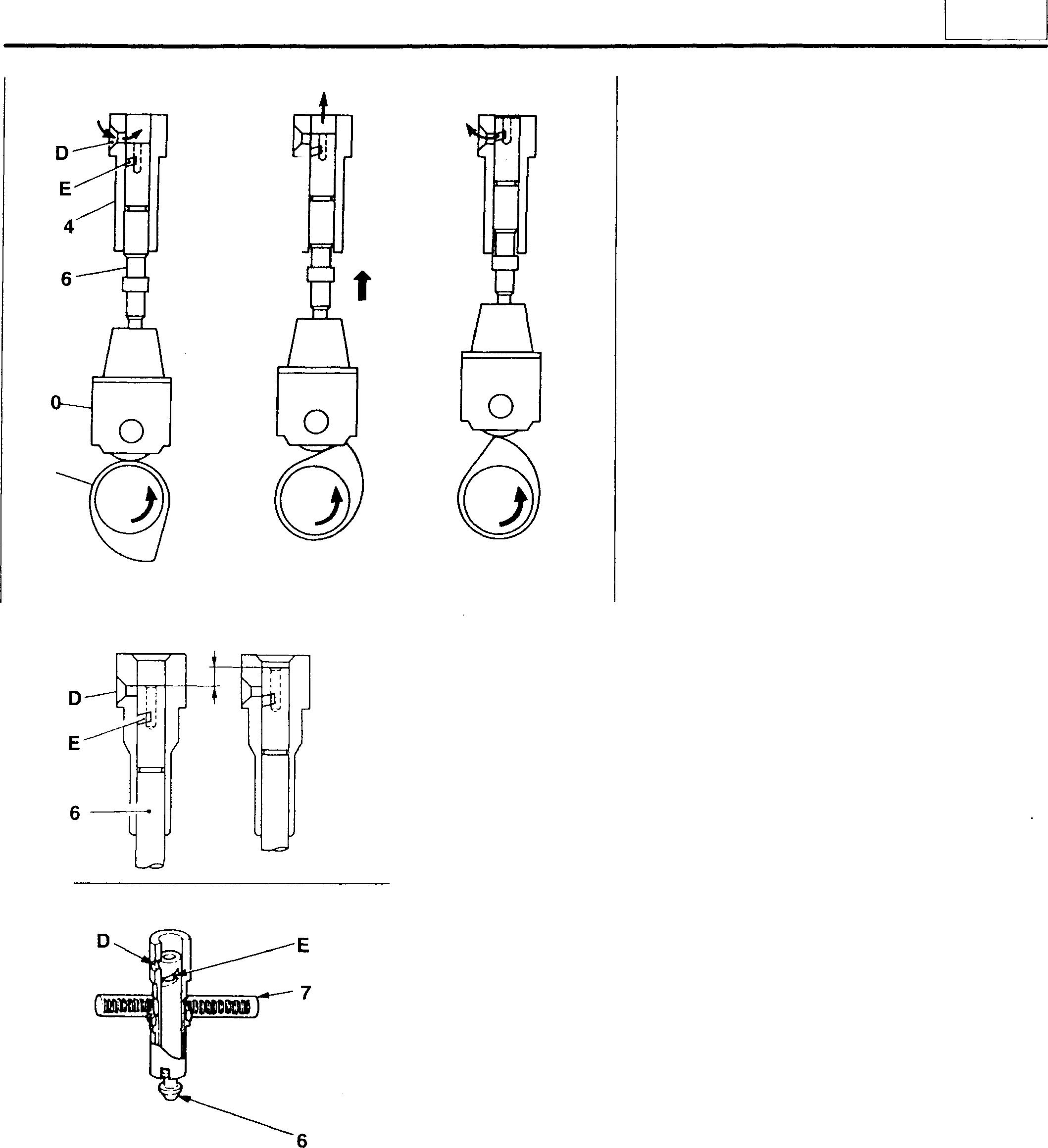
1 11 A B F 01825 01826 C 01824
13
13-7
STRUCTURE AND OPERATION
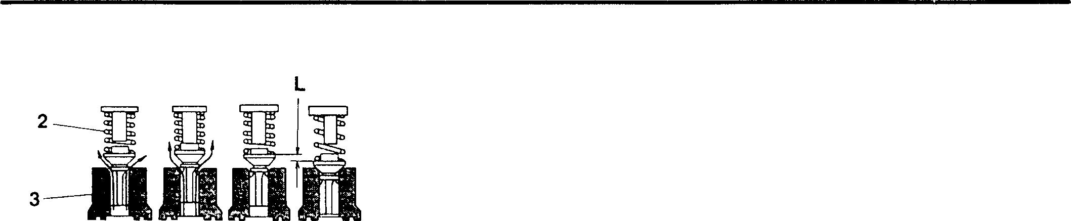
• Delivery valve
G: Pressurizationstarts
H: Injection
J: Pressurization ends (Startingsuction)
K: Suctionends
L: Suctionstroke
Fuel highly pressurized by plunger pushes updeliveryvalve 3 for injection,andwhendeliveryofpressurizedfuelends,deliveryvalvereturnsby the force of delivery valve spring to close fuel passage, thus avoiding reverse flow offuel. Delivery valvelowersfurther to restat its seat, and for this stroke L, residual pressure between delivery valve and injection nozzleisforaninstantlowered.Thisreturnsuctionmakes fuel-cuttingat nozzleseffectiveandavoidspost-injection dripping.
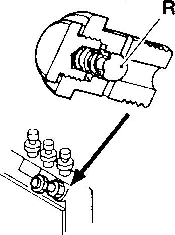
• Overflow valve
Whenthefuelpressureintheinjectionpumpexceedsapresetlevel,the steelballRispushedup,allowingfueltoflowoutfromtheinjectionpump andreturntothefueltank. Thisstabilizesthefueltemperature andtemperature distribution in the injection pump and keeps the injection rate constantineachcylinder.
G H J K
01827
13-8
01830
Governor
<RSV Type>
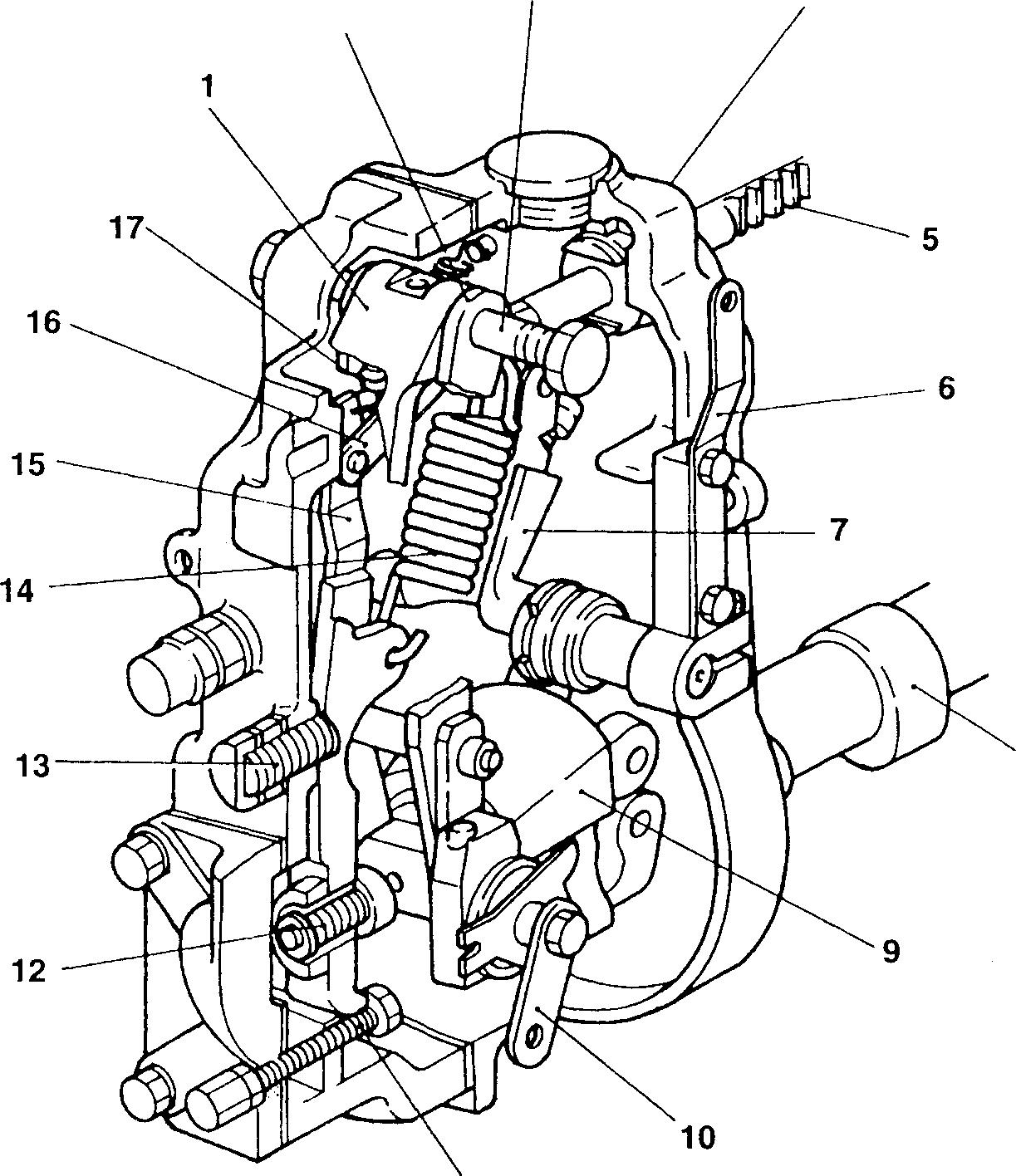
1 Tension lever
2 Guidelever
3 Supporting lever shaft
4 Governorhousing
5 Controlrack
6 Adjusting lever
7 Swivellever
8 Camshaft
9 Flyweight
2 3 11 4 8 10 Stoplever 11 Full-load stopper bolt 12 Ungleich spring or idling spring 13 Idling subspring 14 Governorspring 15 Controllever 16 Shackle 17 Startspring 13 18225 13-9
STRUCTURE AND OPERATION
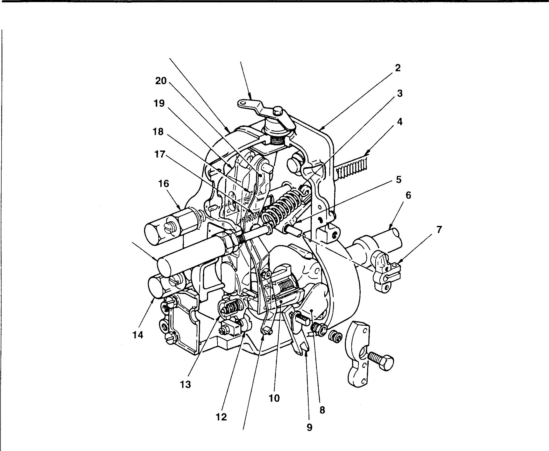
<RFD Type> 21 1 15 11 1 Stop lever 2 Governor housing 3 Governor spring 4 Control rack 5 Swivel lever 6 Camshaft 7 Speed control lever 8 Flyweight 9 Sliding lever 10 Sleeve 11 Floating lever 13-10 12 Stroke adjusting bolt 13 Idling spring 14 Torque spring 15 Smoke set assembly 16 Damper spring 17 Start spring 18 Floating lever link 19 Tension lever 20 Guide lever 21 Governor cover 18227
Tadano Crane Mitsubishi 6D16TLEA Fuel Feed Pump
1 Primingpump
2 Inletcheckvalve
3 Gauze filter
4 Outletcheck valve
5 Feedpump housing
A: From fuel tank
B:Tofuelfilter
• Suction stroke
Thefeedpumpisdrivenbythecamshaftinthe injection pump. The priming pump 1 enables fueltobedrawnupmanuallywhentheinjection pumpisstationary.Itisparticularlyusefulforair bleeding.
The gauze filter 3 removes large impurities fromfueldrawnupfromthefueltankandthus preventscloggingofthefeedpump. Itmustbe washed regularly in gas oil.
Whentheinjectionpumpcamshaft 6 forcesupthepushrod7, fuelinthe suction chamber C is compressed and opens the outlet check valve 4. Most ofthefuelforcedout isdrawn into the pressure chamber D below thepiston.
• Pressure feed stroke
Asthecamshaft 6 turnsandthecamloses itslift, thepiston9 ispushed downbythe pistonspring 8. The fuelinthepressure chamber D is thus forced out andfedtowardthefuelfilter.
Atthesametime,theoutletcheckvalve4closesandtheinletcheckvalve 2 opens. Asaresult, fuel is againdrawn intothesuctionchamber C.
• Stoppage
Whenpressureinthepressurechamber Dexceedsapresetlevel,thepistonspring 8 cannotpushbackthepiston 9. Thepumpthereforestopsoperating, preventingpressureinthefuelfilterfromrisingmorethannecessary.
Mitsubishi 6D16TLEA engine parts contact:
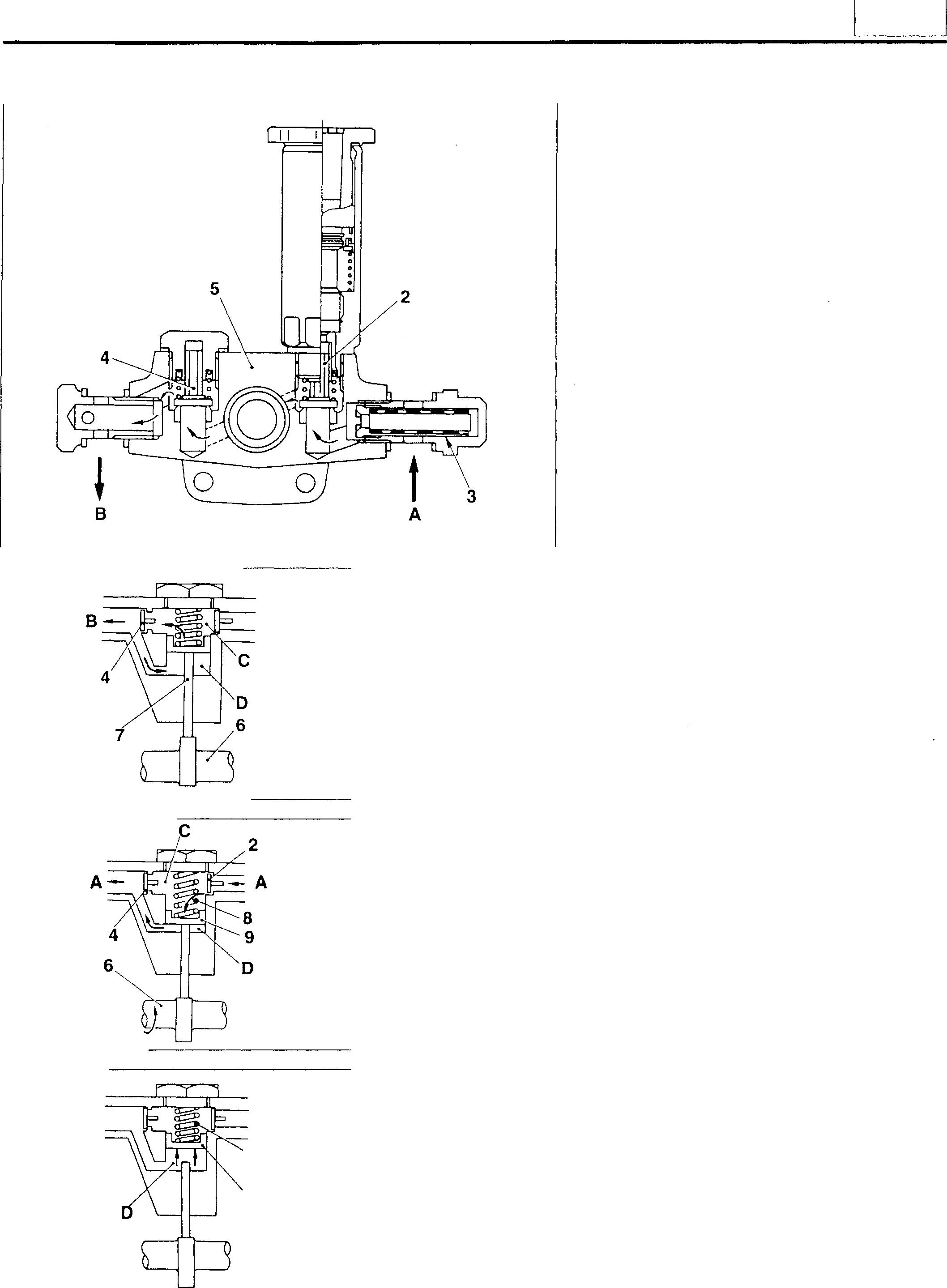
email: engineparts2@gmail.com
Phone: 269 673 1638
Text: 269 760 8652
8
A
9
13912 13913 13914 14431
13
13-11
STRUCTURE AND OPERATION
Automatic Timer
The automatic timer utilizes a mechanical arrangement to adjust the injection timing in accordance with the engine speed. The automatic timer is mounted on the injection pump camshaft using a round nut. Via a driving disk, it is driven by the air compressor crankshaft or pump drive shaft.
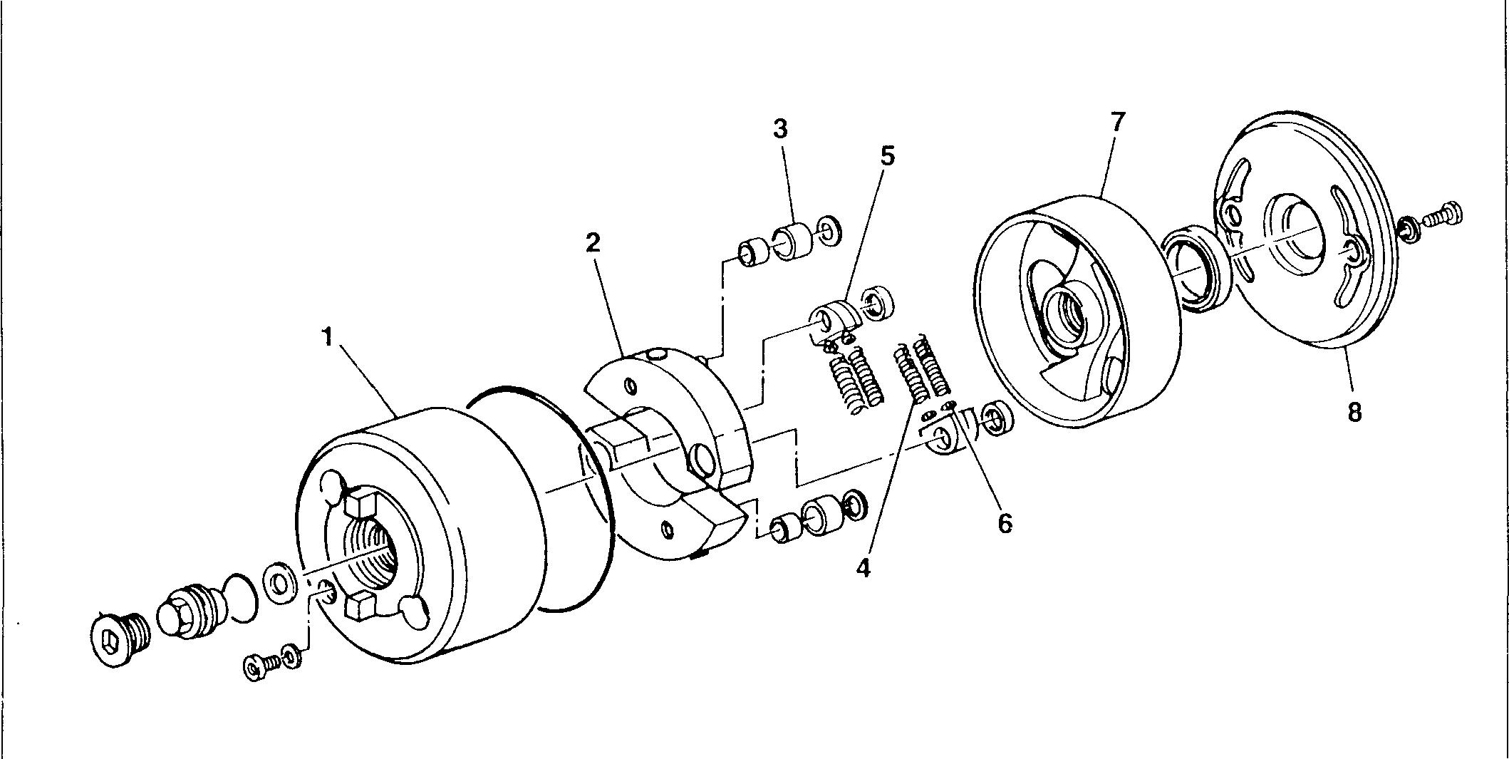
1 Timer housing
2 Flyweight
3 Roller
4 Timer spring
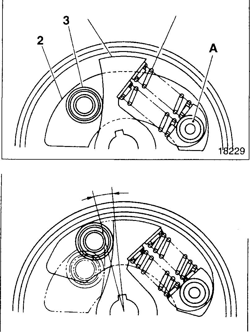
18228
5 Spring seat
6 Shim
7 Flange
8 Cover
• With engine stationary
Whentheengine isstationary, the timerspring 4overcomes the centrifugal force acting on the flyweight 2. The flyweight roller is therefore held down by the flange 7, and the injection timing arrangement is not advanced.
• With engine running
As the engine speed rises, the centrifugal force on the flyweight 2 increases. With the timer housing pin A as the fulcrum, the flyweight roller 3 thus moves outward while pushing the curved surface of the flange 7, causing the flange to compress the timer springs 4. As a result, the roller 3 ofthe flyweight 2 moves the flange 7 inthe rotating directing andtheinjection timing is advanced.
Mitsubishi 6D16TLEA engine parts contact:
email: engineparts2@gmail.com
Phone: 269 673 1638
Text: 269 760 8652
B 13-12 18230
7 4
Injection Pump Drive
1 Pumpdrivecase
2 Bearing
3 Pumpdrivegear
4 Pumpdrive shaft
5 Coupling
A:Timing gearside
B:Timerside
Theinjection pumpdriveisfitted ontotheflywheelhousing on theleftoftheengine. Itisdrivenbytheenginetiminggearathalf the engine speed.
The pumpdrive shaft 4 drivestheinjection pump via the coupling 5onits timerside.
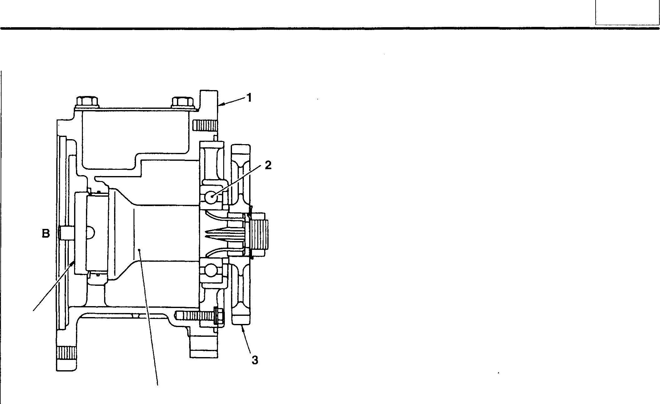
Injection Nozzles
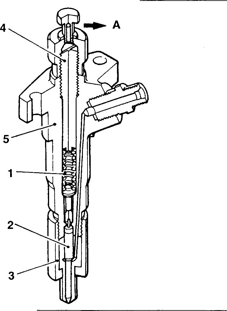
1 Nozzlespring
2 Needle valve
3 Nozzle
4 Adjustingscrew
5 Nozzleholder
A:Toleak-offpipe
B: From injectionpump
Fuel fed from the injection pump enters the nozzle holder 5. Whenthe fuel pressureinthe nozzle holder exceeds apreset pressure, it overcomes the nozzle spring 1, pushes up the needlevalve2,andthefuelissprayedintothecylinderfromthe orifice at the end ofthe nozzle 3.
Some of the high-pressure fuel lubricates the needle valve 2 andreturnstothefueltankviathe leak-off pipe.
Mitsubishi 6D16TLEA engine parts contact: email: engineparts2@gmail.com
Phone: 269 673 1638
Text: 269 760 8652
5
4 A 01844 """"""' B 04538
<1-springtype>
13
13-13
STRUCTURE AND OPERATION
<2-spring
1 Valve opening pressure adjustment shim
2 Prelift adjustment shim
3 1st spring
4 1st push rod
5 Nozzle
6 Needle valve
7 Nozzle holder
8 2nd push rod
9 2nd spring
Inside the nozzle, there are two springs 3, 9 and twopush rods 4, 8. A prelift clearance is provided between the twopush rods. When high-pressure fuel from the injection pump overcomes the 1st spring 3 (this spring determines thevalveopening pressure), the needle valve 6 pushes upthe 1st push rod 4, thereby opening the valve.
When the 1st push rod 4 moves through the prelift clearance and contacts the2ndpush rod 8, theneedlevalve 6 momentarily stops lifting. As the fuel pressure increases further and overcomesthecombined forceof the 1st spring 3 and 2nd spring 9, the needlevalve 6 lifts again for the main injection.
Mitsubishi 6D16TLEA engine parts contact:
email: engineparts2@gmail.com
Phone: 269 673 1638
Text: 269 760 8652
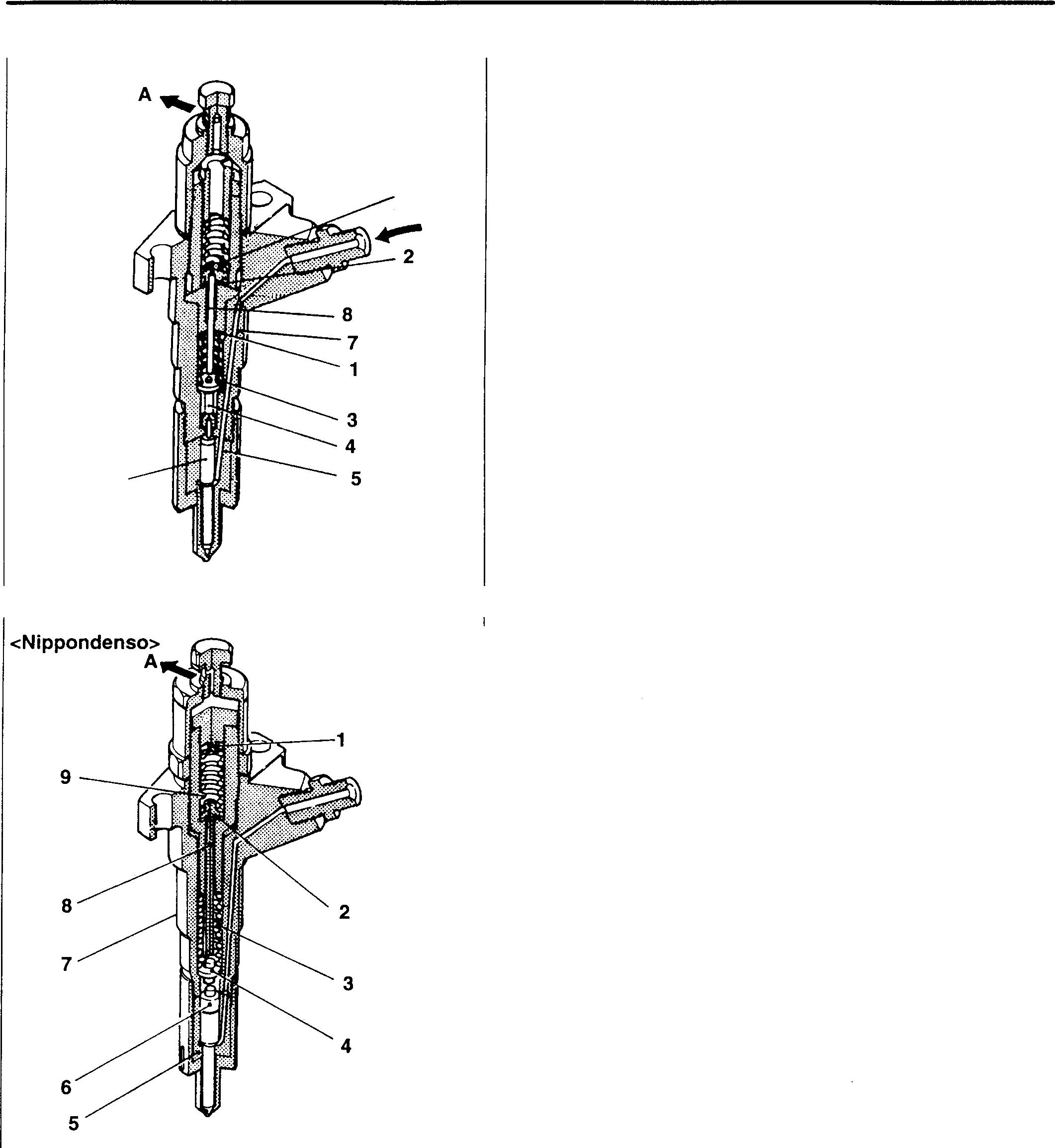
18362
type>
<Zexel> 9 B 6---
18361 .,_-s
13-14
13 MEMO 13-15
TROUBLESHOOTING
Mitsubishi 6D16TLEA engine parts contact: email: engineparts2@gmail.com
Phone: 269 673 1638
Text: 269 760 8652
Symptoms -0 <l) <l) 0.. Cf) .c E .!2> O'l :::J C E t 0 <1l ·x .8 en <1l :t= :3 -0 .... E :;:; :3 0.. <l) <l) .c Cf) t :3 <l) Ol -1= <1l 0.. C (.) 0 t en :3 0 0.. <1l <1l .8 0.. Cf) :2 C � <1l 0 <l) 0 0.. en .8 <l) -� E <l) 0 0 en iii :::J 0 C Ol :::J -� Cf) -0 Cf) 0 Cl) E C 0 <l) _::,: Ol C Ol Cl) 0.. ai C (.) (..) C <l) ·x C 0.. Cf) C .2 - :i= 0 <l) c <1l <l) 0 <l) = 0 C 0 -� 'o _::,: <l) <l) E <l) en -0 -� � ::i:i u ::i:i <l) <l) Cl) <l) Cl) <l) <l) �� -� C -� <1l :i= C <1l C C C en en <l) <l) Ol Ol Ol :::J Ol Ol Ol Ol (.) Q) C C C C Cf) C C C C C (.) Possible causes ww w :::, C w :::i w w w <( 0Injection pump Sticky plunger 0 proper Sticky control rack 0 Sticky delivery valve 0 Worn tappet 0 Worn camshaft 0 Poorly adjusted injection timing 0 00 0 Worn plunger 0 0 Defective delivery valve seat 0 Excessively advanced injection timing 0 Insufficient plunger slide stroke 0 Broken plunger spring 0 0 Defective sliding action in control rack 0 0 00 Tappet worn or not sliding correctly 0 Broken delivery valve spring 00 Poor airtightness due to loose delivery valve holder 00 Defective delivery valve operation 0 Loose control pinion 0 Plunger spring not seating correctly 0 Delivery valve holder too tight 0 Uneven injection volume to cylinders 0 0 Fuel feed pump Gauze filter clogged 0 00 Check valve not operating 0 Sticky piston 0 Sticky push rod 0 Worn tappet 0 Defective check valve operation 0 0 0 Piston worn 0 0 0 13-16
13 Symptoms Q) Q) 0. (/) ..c E .Ql Ol ..c C E ·-e 0 en x .8 U) co :i:: "5 cJ .... E � t "5 0. Q) Ol Q) 0. "5 Q) .t (.) 0 co "5 0 0. _s; en en -.8 t U) (/) :2 C � 0. ci co 0 Q) .8 0. U) .8 .£;; E 0 cii :::, Q) Q) 0 0 (/) cJ - C Ol :::, C (/) (/) 0 (/) E C 0 Q) :::, .:,,:. "6> C "6> (/) 0. Q) C (.) (.) C Q) x C 0. (/) C .2 :E 0 Q) c co Q) 0 Q) 0 C 0 "3: '6 .:,,:. Q) Q) E Q) U) cJ "3:cii Q) :0·c::; :0 ai Q) Q) Q) Q) Q) Q) (I) n C C C co:E C co C C C Q) "6> "6> Ol U) :::, "6> U) "6> "6> "6> (I) (.) ai C C C C (/) C C C C C Possible causes LU LU LU :) C LU :) w LU LU <( DGovernor Insufficient full-loadstopperposition 0 Weakgovernorspring 0 0 Incorrectlyadjustedcontrollever 00 0 Flyweightsnotoperatingeffectively 0 Weakidlingspring 0 Bentlinks 0 Excessivefrictionorplayinlinks 0 Looseroundnut 0 Poorlyadjustedidlingsetbolt 0 Defectiveslidingactionincontrollever 0 Stop mechanismdamaged 0 Automatic timer Defective advancingaction 0 0 Injection nozzles Stickyneedlevalve 0 Valveopeningpressuretoolow 0 0 Blockedinjectionorifice 0 0 0 0 0 Poorairtightnessinnozzle 0 0 0 0 0 Valveopeningpressuretoohigh 0 Brokenspring 00 Defective slidingactioninneedle valve 0 Defective valveopeningpressure 0 Weakness/deteriorationinspring 0 Fuel filter Filter (and/orsecondaryfilter) clogged 0 0 0 0 Fuel tank empty 0 Fuel pipes blocked and/or fuelleakingfrom connections 0 Airor waterinfuel system 0 0 0 0 Low-quality fuelinuse 0 0 0 0 Cracked fuel pipe Leaky fueltank ,_' Incorrect oil viscosity Gr.12 0 Incorrect valve clearance Gr.11 0 0 Defective headgasket O]Gr.11 0 0 Wear and/orcarbondepositson valveand valve seat [DGr.11 0 0 Weakness/deteriorationin valve spring illGr.11 0 0 13-17
TROUBLESHOOTING
Mitsubishi 6D16TLEA engine parts contact: email: engineparts2@gmail.com
Phone: 269 673 1638
Text: 269 760 8652
Symptoms '"O (I) (I) Cl. CJ) .c E .!2> D) :::, .c C E --e 0 (1j ·x .9 en (1j :i:: 5 '"O .... E � t: 5 Cl. (I) D) (I) .c Cl. 5 (I) .i:: CJ 0 (1j 5 0 Cl. .£ (1j (1j .9 >, t en CJ) :2 C � Cl. ci. cu 0 (I) 0 Cl. en .9 (I) .£ E (I) 0 0 en <ii :::, :::, 0 '"O CJ) 0 +-' CJ) .£ D) E C CJ) C 0 (I) :::, � D) C D) CJ) Cl. <ii C CJ CJ C (I) ·x C Cl. CJ) C 2 ;E 0 (I) c (1j (I) 0 (I) 0 C 0 "§: '"O � � (I) E (I) en '"O "§: cO (I) "c:5 ::0 .... > (I) (I) (I) .0 (I) (I) (I) (I) (I) u C C C (1j :E: C cu C C C a3 "5> "5> "5> en :::, "5> en "5> "5> 5> QJ CJ Q) C C C C CJ) C C C C C CJ Possiblecauses LU LU LU ::) C LU ::) LU LU LU � 0Worn/damaged piston ring(s) []JGr.11 0 0 Worn/damaged piston ring groove(s) [lJGr. 11 0 0 Worn piston and cylinder liner [DGr. 11 0 Cooling system malfunctioning [DGr. 14 0 0 Defective starter switch [lJGr. 54 0 Defective glow relay [DGr. 54 0 13-18
I 1a I MEMO 13-19
ON-VEHICLE INSPECTION AND ADJUSTMENT
Checking and Adjusting Injection Timing
Service standards
- Fuelinjection timing (BTDC)
0 Tightening torques
Bolt (injection pipe lock plate)
on specifications - Adjust
to
(0.45 to0.6}
to0.5}
to54 (5 to5.5}
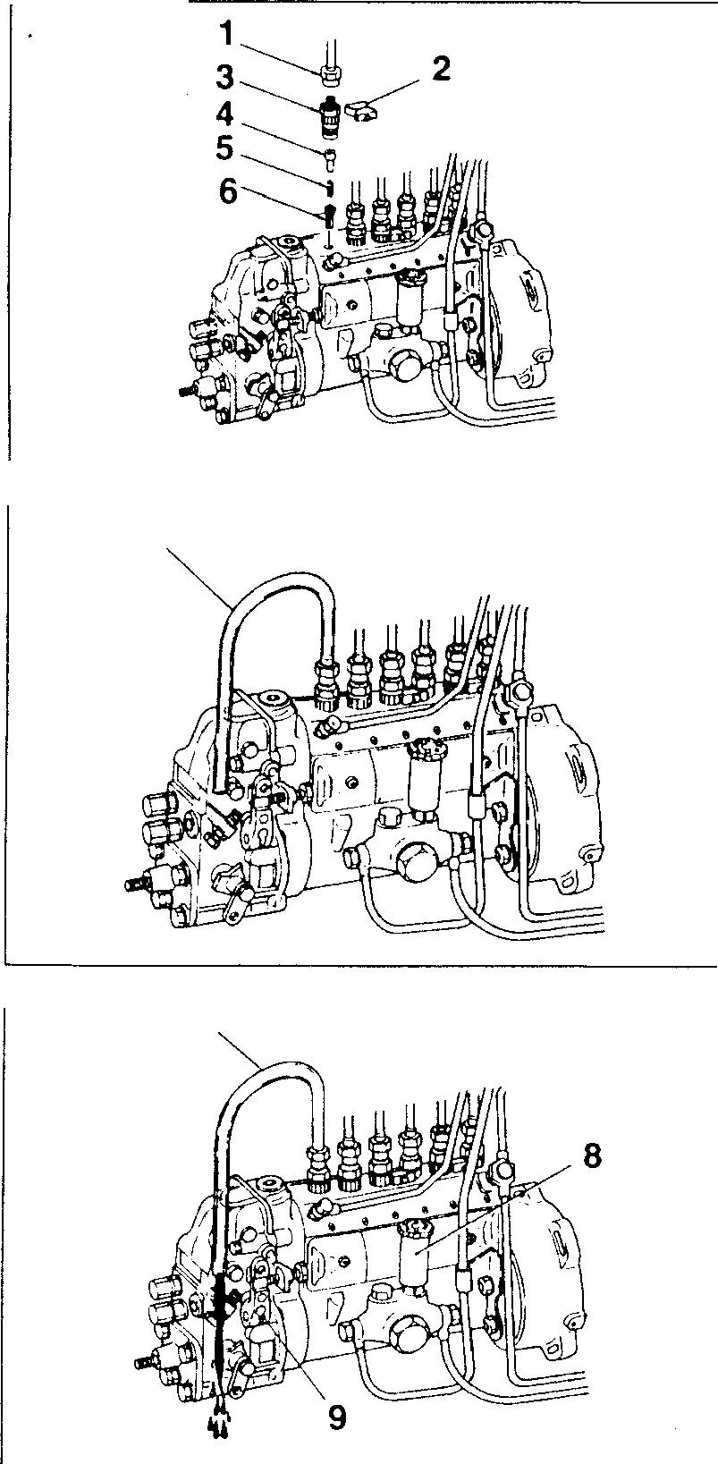
[Inspection]
• From the injection pump's No. 1 cylinder, remove the injection pipe 1, lockplate 2, delivery valve holder 3, stopper4, delivery valve spring 5, and delivery valve 6.
• Fit the delivery valve holder 3.
CAUTION&,_--------------
Place all partsin gas oil afterremoval to keepthemfree ofdust.
• Fit an injection pipe 7 onto cylinder No. 1. Point the pipe's other end downward such that fuel flowing out can be seen clearly.
• Rotate the crankshaft pulley clockwise (as seen from the front of engine) by at least 180° and bring cylinder No. 1 to approximately 30° BTDC on its compression stroke.
NOTE
Iftheengineisturnedinitsreversedirection(whenstoppingthe engine or by cranking), the automatic timer may stay in an advanced condition. Thismaynot be cancelled bya slight forward rotationoftheengine. Besuretocranktheengineforwardmanually by at least 180°
• Feed fuel into the injection pump using the priming pump 8. With fuel flowingoutoftheinjection pipe7, crankthe engineslowlyclockwise (as seen from the front of engine).
NOTE
Ensure that the stop lever 9 at the side of the governor isnot in its STOP position.
Location Maintenance item Standard value Limit Remedy
Depends
Unit: N ·m {kgf·m} Location 1 2 3 7 13-20 Parts to be tightened Tightening torque Remarks Union nut
25
-
Delivery
holder 7 Nippondenso 7.8
11
Zexel A-type 4.4
Zexel AD-type 3.4
Nippondenso 34 to 39 (3.5to
Zexel A-type 39 to 44 (4
Zexel AD-type 49
-
(injectionpipemounting)
{2.5}
valve
to
(0.8 to1.1}
6.0
to 4.9 (0.35
4}
to 4.5}
18934
18935
18936
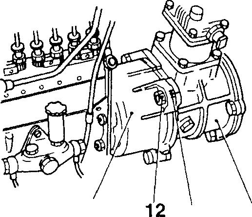
• Whentheflowoffuelfromtheinjectionpipe7diminishes,cranktheenginemoreslowly.Whentheflowoffuelstopscompletely,stopcranking theengine.
• Checkthatthepointer10 ontheflywheelhousingortorsionaldamper B indicatesthe value 1° earlierthanthecorrect fuel injection timing.
A: Flywheel
NOTE
• Theinjection timing in this measurementbecomes1° earlier than the correct injection timing due to the inactivation of the delivery valve spring.
• The correctinjection timing is indicated on the plate attached on the rocker cover.
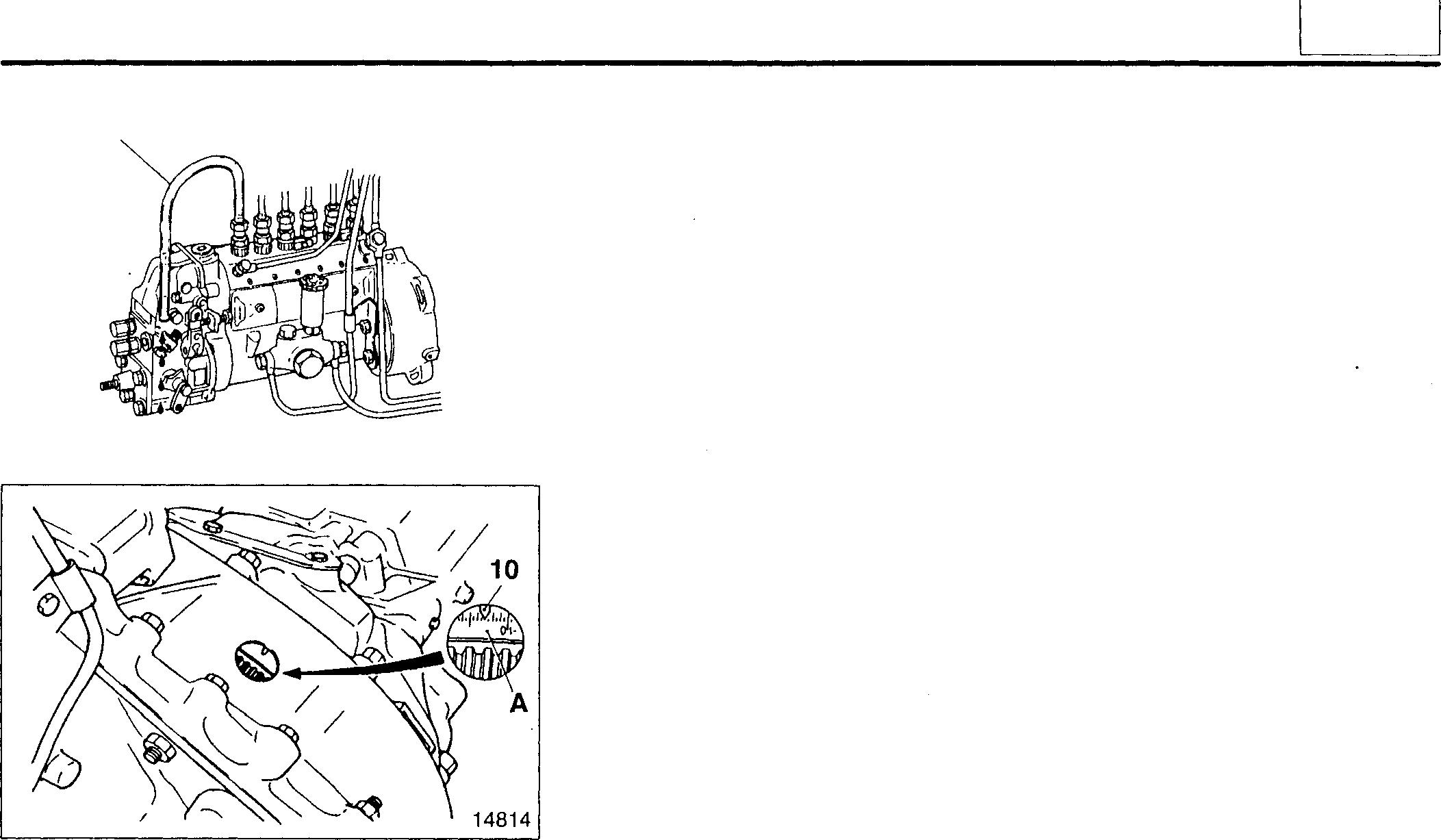
• Iftheinjectiontimingshouldbemeasuredinadustylocation, perform asfollows:
• Rotate the crankshaft pulley clockwise (as seen from the front of engine)andbringtheNo. 1 cylinderto30° BTDConitscompression stroke.
• Disconnecttheinjectionpipe1 witha littleamountoffuelremained atthe topofthe deliveryvalveholder 3.
• Slowly rotate the crankshaft pulley clockwise. When the injection timing is reached, the fuelat the top of the delivery valve holder 3 startsto move.
• Iftheinjection timingisoutof thespecification, adjust as follows:
[Adjustment]
• Loosenthenuts 12 thatholdthetimercase 11 ontothepumpdriveor aircompressor 13.
• Ifthefuelinjectiontimingisoverlyretarded, inclinetheinjectionpump toward the crankcase.
• Ifthefuelinjectiontimingisoverlyadvanced, inclinetheinjectionpump away fromthe crankcase.
NOTE
Turning the injectionpump by one of the gradations inscribed on the timer caseflange C causesa6° change in the injection timing.
• Tighten thenuts 12, thencheck thefuel injectiontimingagain.
NOTE
If the fuel injection timing is so far out of specification that adjustmentwith the injectionpump is notpossible, theengine timing gear and injection pump drive gear may not be meshing correctly. If this occurs, removeandrefittheaircompressororinjectionpump drive.
• Air compressor: OJ Gr. 61
• Injection pump drive: OJ P.13-30
• Aftercheckingthatthefuelinjectiontimingisuptospecification, fitthe deliveryvalve 6, deliveryvalve spring 5, and stopper 4.
7
11
13
18937
C 13 01852
13-21
ON-VEHICLE INSPECTION AND ADJUSTMENT
• Tighten each part to its specified torque.
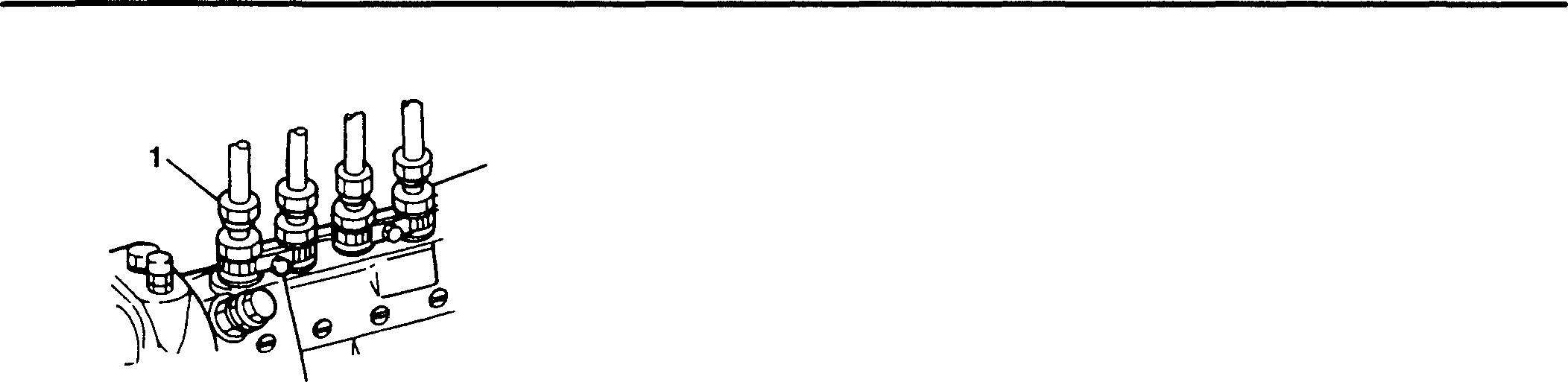
Checking and Adjusting Minimum and Maximum No-load Speeds
Service standards
Location Maintenance item - No-loadminimum speed - No-loadmaximumspeed
<RSV-type governor> 1
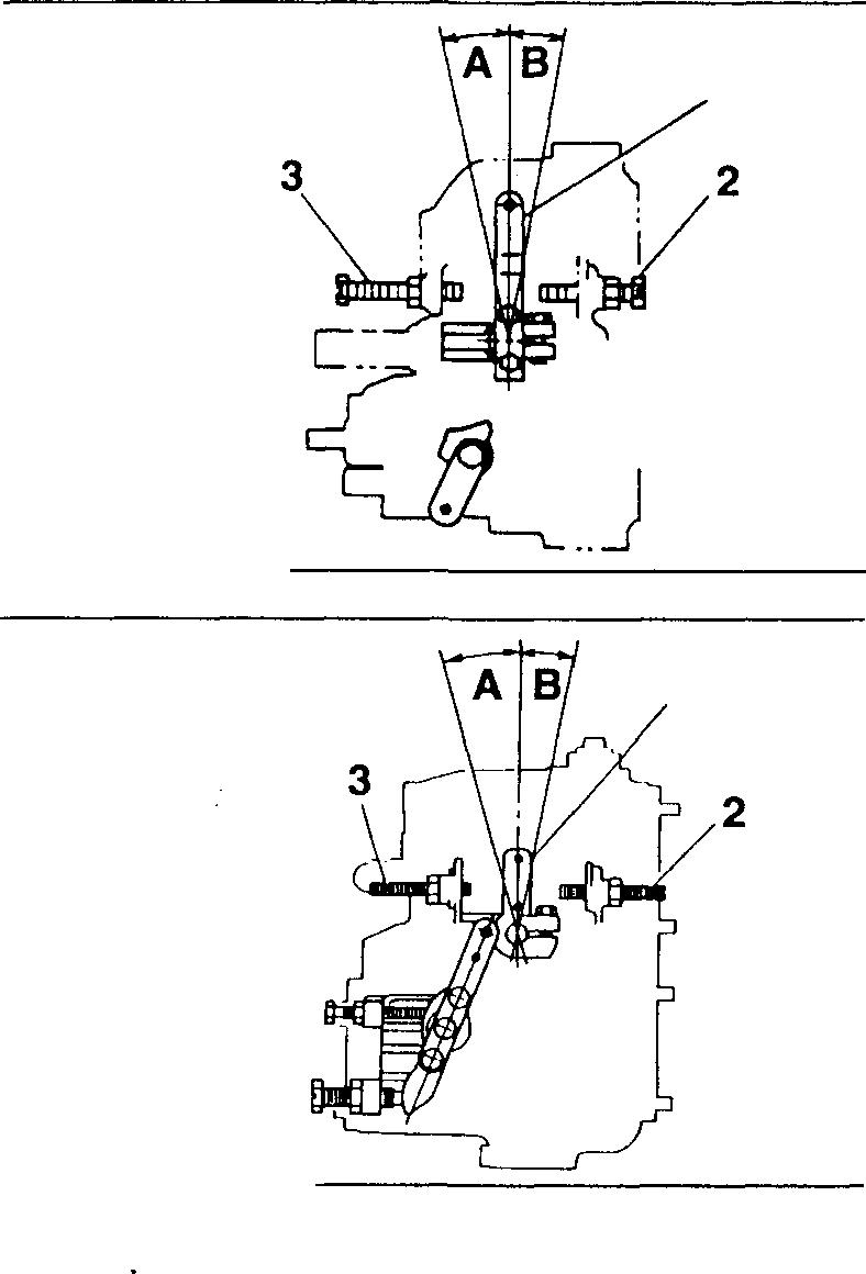
Standard value Limit Remedy
Depends on specifications - Adjust
Depends onspecifications - Adjust
Start the engine and allow it to warm up before carrying out the following inspections.
• No-load minimum speed [Inspection]
Confirmthatthecontrollever 1 istouchingtheidlingset bolt3. Thencheck that the minimum speed is up to specification.
A: Idling position
[Adjustment]
If the minimum speed is out of specification, adjust it using the idling set bolt 3.
• No-load maximum speed [Inspection]
Confirmthatthecontrollever 1 istouchingthefull-speed set bolt 2.Then, check that the maximum speed is up to specification.
B: Full-speed position
[Adjustment]
Ifthe maximum speedisoutofspecification,adjustit using thefull-speed set bolt 2.
NOTE
Check that the engine does not stall and that no hunting occurs when the control lever 1 is moved quickly from the full-speed position to the idling position. If any abnormality is.apparent, make adjustments within the specified range.
3
2 01853
18231
13-22
<RFD-type governor> 1 18232
• No-load minimum speed
[Inspection]
Confirmthattheloadcontrollever7 istouchingtheidlingsetbolt 6. Then checkthatthe minimum speed is upto specification.
A:Idlingposition
[Adjustment]
Ifthe minimumspeedisoutofspecification, adjustitusingtheidling set bolt 6.
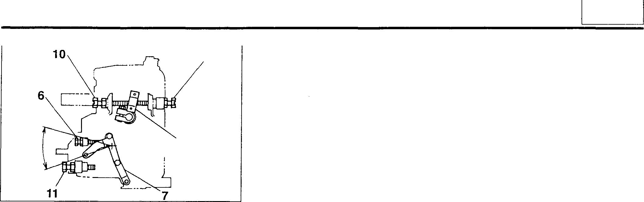
• No-load maximum speed
[Inspection]
Movetheloadcontrollever7tothefull-loadposition B.Then,checkthat the maximumspeedis up to specification.
[Adjustment]
Ifthemaximumspeedisoutofspecification, adjustpositionofthespeed controllever 8 usingthemaximumspeed stopperbolt 9 andstopperbolt 10.
NOTE
• Do not alter the position of the full-load stopper bolt 11.
• Check that the engine does not stall and that no hunting occurs when the load control lever 7 is moved quickly from the full-load position to the idling position. If any abnormality is apparent, make adjustments within the specified range.
Cleaning Fuel Feed Pump Gauze Filter
0
torques
N·m {kgf·m}
to 29 {2 to 3}
to 20 {1 .5 to 2}
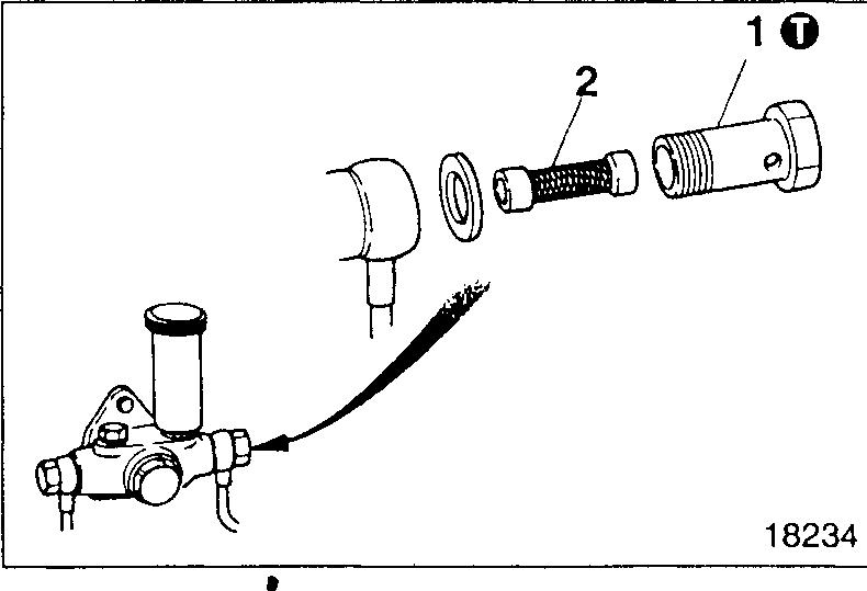
• Removetheeyebolt1 fromthesuctionportsideofthefuelfeedpump.
• Remove thegauzefilter 2 from theeyebolt 1.
• Cleanthegauzefilter2.
• Refitthe gauze filter 2 and eyebolt 1 inthe oppositeorderto their removal.
• Bleed allairoutofthe fuel system.
• Start the engineand checkforfuelleaks.
Mitsubishi 6D16TLEA engine parts contact: email: engineparts2@gmail.com
Phone: 269 673 1638
Text: 269 760 8652
9 B 8 A 18233
13
Tightening
Location Parts
betightened 1
Zexel Nippondenso Tighteningtorque Remarks 20
15
Unit:
to
Eyeball
-
13-23
6D16TLEA FUEL FILTER
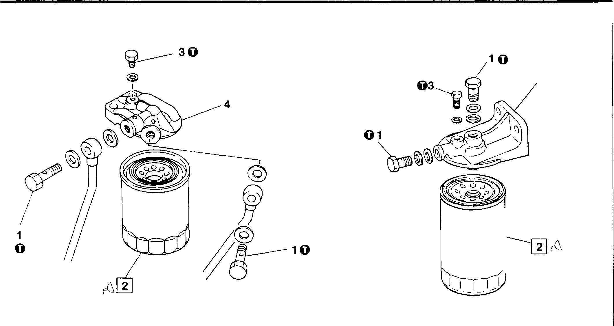
• Disassembly sequence
1 Eyebolt
2 Fuel filter
• Assembly sequence
Reverse theorder of disassembly.
0 Tightening torques
Location Parts to betightened
1 Eyebolt
3 Air vent plug
� Oils
Location Points of application
2 Gasket between fuel filter and fuelfilterhead
� Special tools
Location Tool name and shape
Filter Wrench
Part No. A
2 MH061509 90.2
MH061572 94.2
3 Air ventplug
{3.5}
Mitsubishi 6D16TLEA Tadano Crane
±2.0 {1 ±0.2}
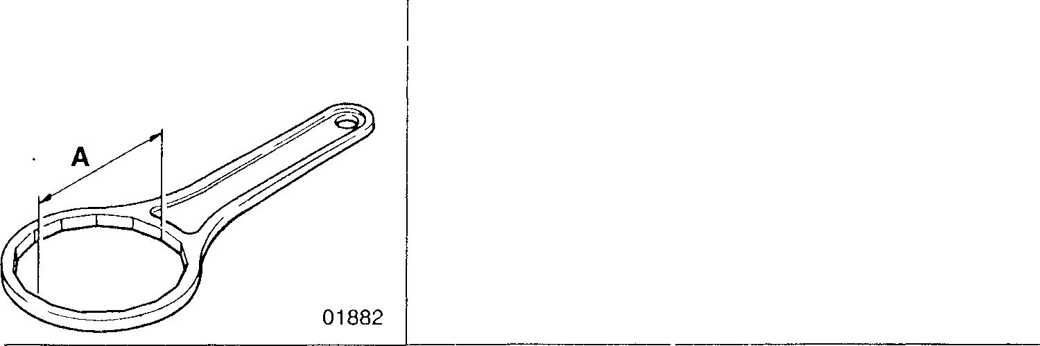
MH061509
Mitsubishi 6D16TLEA engine parts contact: email: engineparts2@gmail.com Phone: 269 673 1638 Text: 269 760 8652
13-24 18235 4 18236
4
head Unit: N·m {kgf·m} Tightening
Remarks 34
9.8
Kinds Quantity Engineoil As required Part
Application
Fuel filter
torque
No.
MH061572 Removingfuel filter
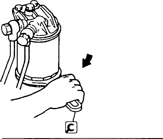
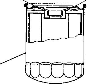
♦ Service procedure @ Fuel filter
[Removal]
WARNING&_-------------
• Fuel is highly flammable; keep it away from flames and sources of heat.
• To minimize the risk of fire, wipe up any spilled fuel.
[Installation]
WARNING&_------------
Use of an unsuitable fuel filter 2 can lead to fuel leaks and fires. Be sure to use a genuine Mitsubishi filter.
• To fit the fuel filter 2, turn it until the gasket C touches surface B of the fuelfilter head4. Then, tighten thefilter by 3/4 to 1 turn. Besure to turn the filter by hand.
• Start the engine and checkfor fuel leaks.
01883 4 � 2 13220 13
13-25
TLEA SECONDARY FUEL FILTER/WATER SEPARATOR
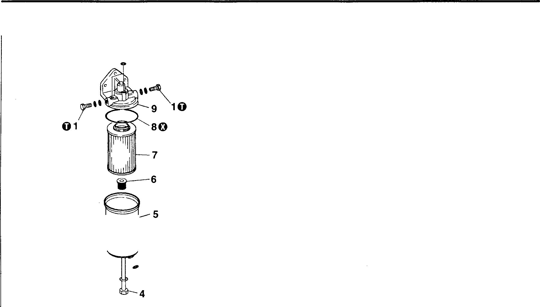
�3
0 Tightening torques
Location Parts to be tightened
1 Eyeball
• Disassembly sequence
Eyebolt
0: Non-reusable part
• Assembly sequence
Reverse the order of disassembly.
Tightening torque 34 (3.5}
Unit: N·m {kgf·m}
Remarks -
6D16
i-2
SECONDARY FUEL FILTER
13-26 18237
1
2
3 Drain
4 Center
5 Case 6 Spring 7 Element 8 O-ring 9 Fuel
Air vent plug
plug
bolt
filter head
6D16TLEA WATER SEPARATOR
• Disassembly sequence
1 Eyebolt
2 Airvent plug
3 O-ring
4 Drain plug 5 Ringnut
6 Case
7 Isolation plate
8 Screenassembly 9 Baffleplate
1O Water levelring
Head 12 O-ring
0:Non-reusablepart
WARNING_&.-----------
• Fuel ignites easily. Do not get it near flame or heat.
• Wipe up any spilled gas oil because it can cause a fire.
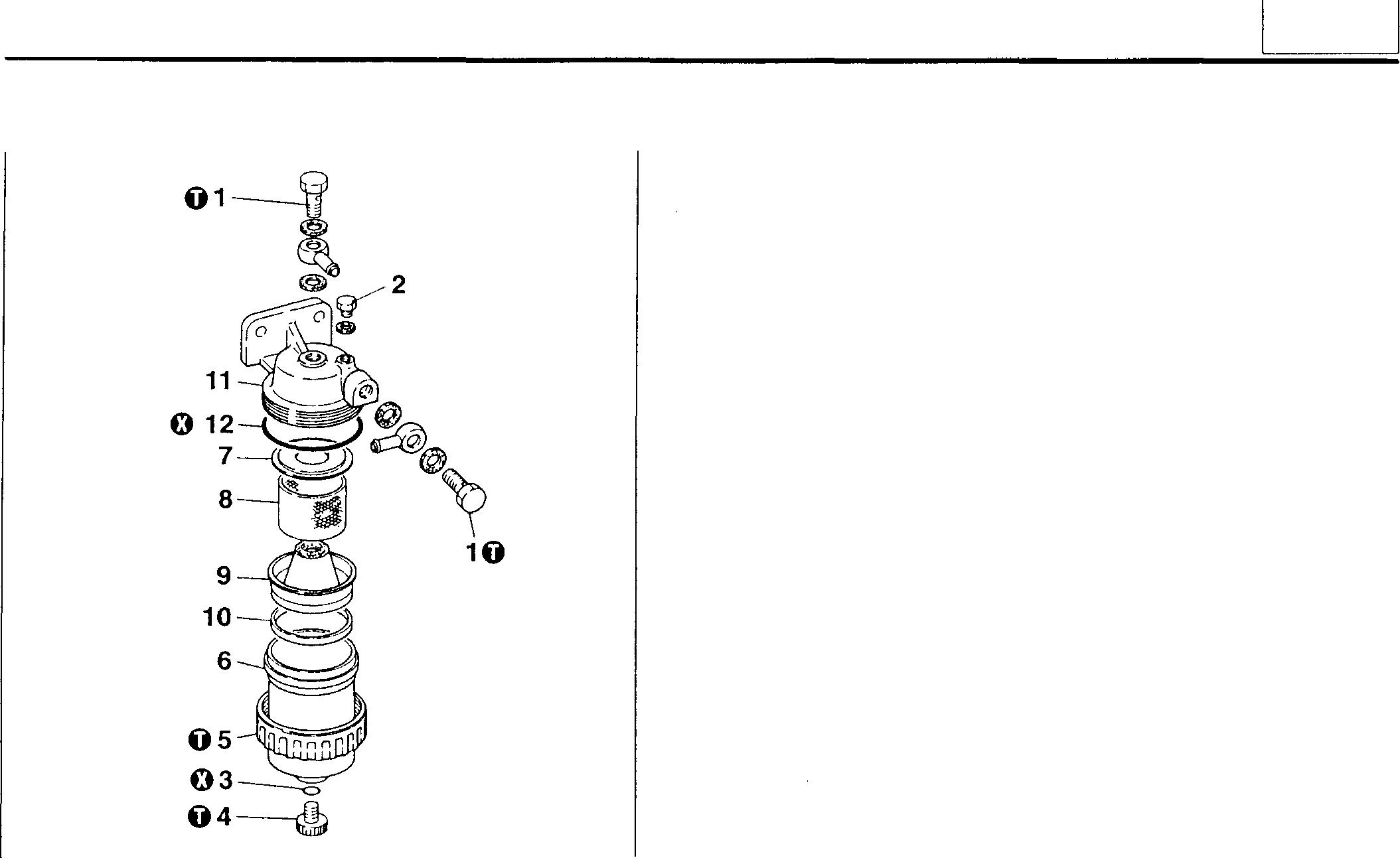
20305
• Assembly sequence
Reverse the order ofdisassembly.
0 Tightening torques
Location Partsto be tightened
1 Eyebolt
5 Airvent plug
7 Drain plug
8 Ring nut
Unit: N·m {kgf·rn}
{3.5}
to 12 {0.8to 1.2}
to3.9 {0.3 to0.4}
to7.8 {0.6 to0.8}
11
13
Tighteningtorque Remarks 34
7.8
2.9
5.9
13-27
-
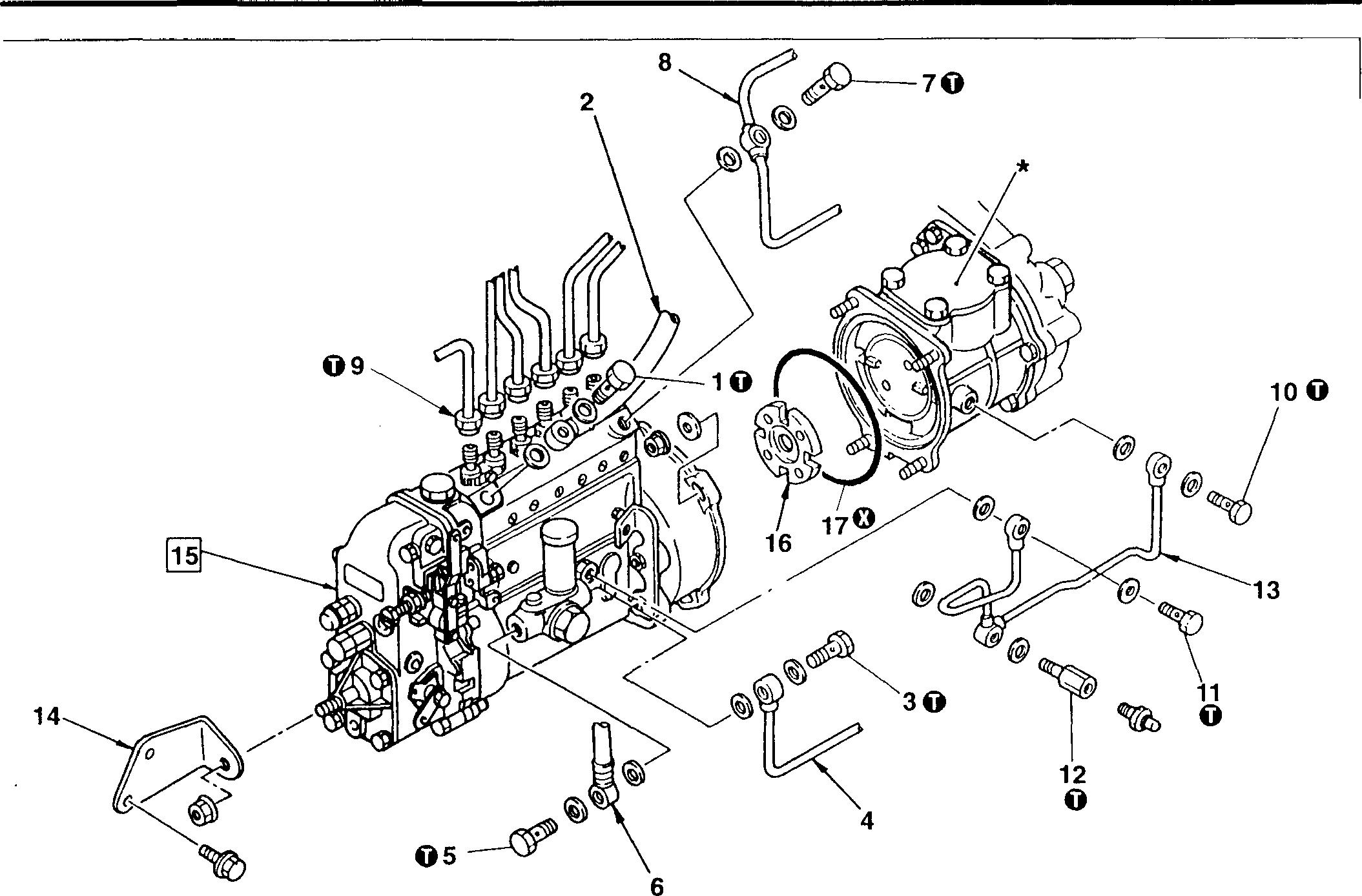
*:Air compressor [O Gr. 61, or
WARNING&_-
• Fuel is highly flammable; keep it away from flames and sources of heat.
• To minimize the risk of fire, wipe up any spilled fuel.
CAUTION&_--------------------------
Dirt particles in the injection pump assembly 15 can seriously detract from engine performance. To prevent the ingress of dirt, cover all pipes, hoses, and other parts after removal.
NOTE
For maintenance of the injection pump assembly 15, please contact a Zexel service station.
MITSUBISHI 6D16TLEA TADANO CRANE > INJECTION
Disassembly sequence 1 Eyebolt 2 Fuelfeedhose 3 Eyebolt 4 Fuel suction pipe 5 Eyebolt 6 Fuelfeedhose 7 Eyebolt • Assembly sequence Reversethe order ofdisassembly. 8 9 10 11 12 13 14 18238 Fuel returnpipe 15 Injection pump assembly Injectionpipe 16 Driving disk Eyebolt 17 0-ring Eyebolt Connector
PUMP •
Oil pipe injection
Injectionpumpstay 0
pumpdrive[O P.13-30
:Non-reusablepart
13-28
Eyebolt (fuel suctionpipe, fuel Zexel
feedhose)
pipeunion
side)
Eyebolt (oil pipe; injectionpump side)
Connecter (oil pipe)
{2 to2.5}
to2}
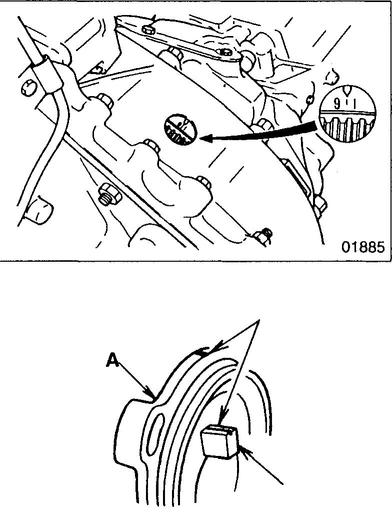
♦ Service procedure
� Installing injection pumpassembly
• Bring cylinder No. 1 ofthe engine to the TDC position of its compression stroke.
• Align the inscribed lines C on the timer case A and timer B. Then, fit the injection pump assembly 15 onto the air compressor or injection pump drive.
Mitsubishi 6D16TLEA engine parts contact:
email: engineparts2@gmail.com
Phone: 269 673 1638
Text: 269 760 8652
13 0 Tightening torques Unit: N·m {kgf·m} Location 1, 7 3,5 9 10 11 12 Parts to be tightened Tightening torque Remarks Eyebolt
fuel re- Zexel 20 to29 {2 to3}turn
Nippondenso 15to20 {1.5
-
(fuelfeed hose,
pipe)
to2}
20
25
-
Nippondenso 15 to20 {1.5
Injection
nut 25 {2.5} -
compressor or
drive 21 {2.1} -
to
Eyebolt (oilpipe; air
pump
C B Zexel 10 to13 {1 to
Nippondenso 7.8to13 {0.8to
21 {2.1} -
1.3}
1.3}
13-29
01886
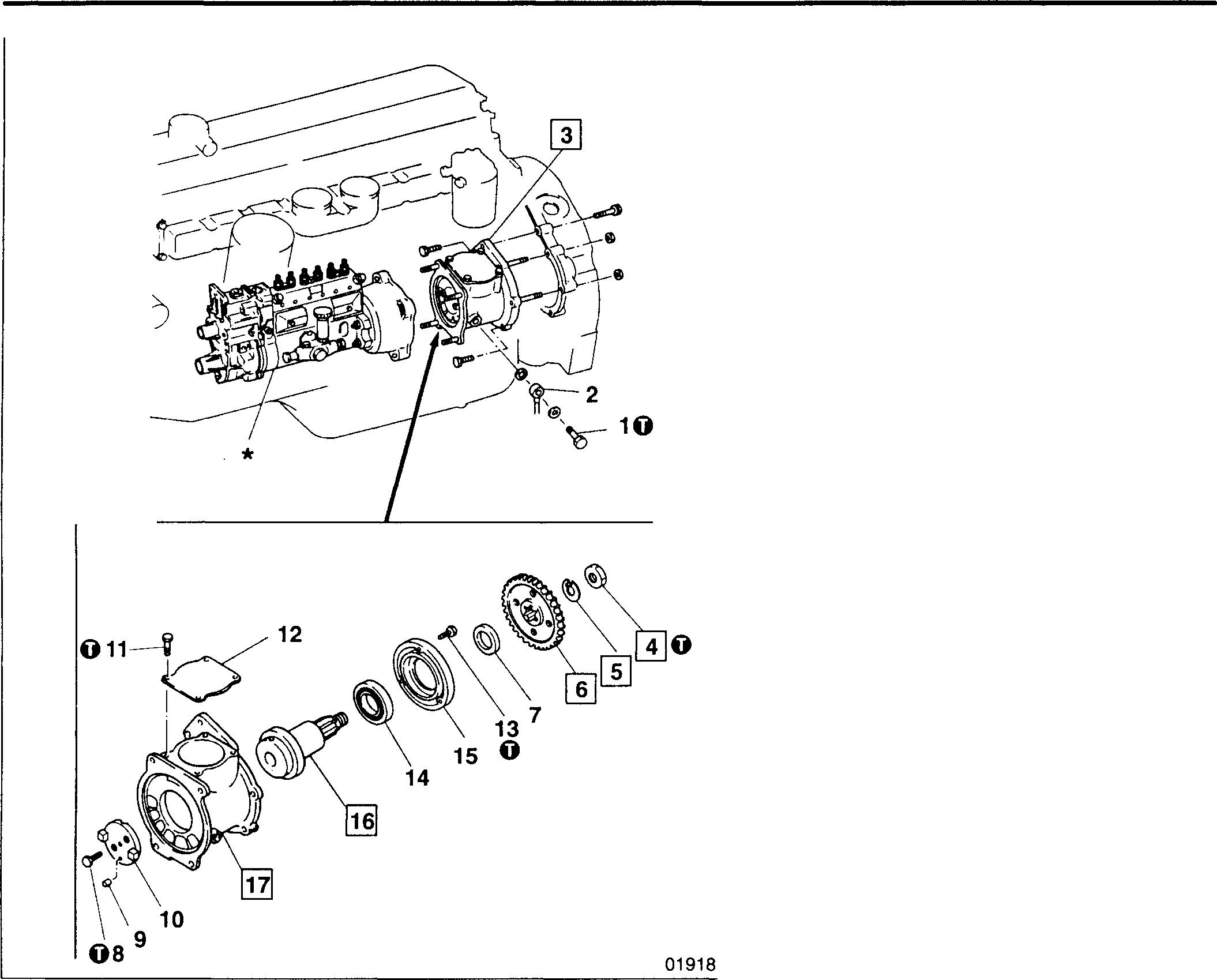
*: Injection pump assembly ffi P.13-28
• Assembly sequence
the order of disassembly.

MITSUBISHI 6D16TLEA TADANO INJECTION
Service standards Location Maintenance item 16 , Pump drive shaft end play 16, 17 Pump drive shaft-to-pump drive case clearance
Location Parts to be tightened 1 Eyeball 4 Nut (drive gear mounting) 8 Bolt (coupling mounting) 11 Bolt (cover mounting) 13 Bolt (bearing holder mounting) 13-30
PUMP DRIVE
0 Tightening torques
sequence 1
2 Oil pipe 3
assembly 4 Nut 5 Lock washer 6 Drive gear 7 Collar 8 Bolt 9 Pin 10 Coupling 11 Bolt 12 Cover 13 Bolt 14 Bearing 15 Bearing holder 16 Pump drive shaft 17 Pump drive case
• Disassembly
Eyebolt
Injection pump drive
Reverse
Unit: mm Standard value Limit Remedy - 0.59 Replace - 0.12 Replace pump drive case Unit: N -m {kgf·m} Tightening torque Remarks 21 {2.1}167to 211 {17to 21.5}30to 36{3.1 to 3.7}25to 29 {2.5to 3}5.9 to 6.9 {0.6to 0.75} -
6D16TLEA
contact: email: engineparts2@gmail.com Phone: 269 673 1638 Text: 269 760 8652
Mitsubishi
engine parts
♦ Service procedure
@] Installing injection pump drive assembly
• Bring cylinder No. 1 of the engine to the TDC position of its compression stroke. [O Gr. 11
• AligntheinscribedlineAonthedrivegear6oftheinjectionpumpdrive assembly 3 with the inscribed line A on the pump drive case 17.
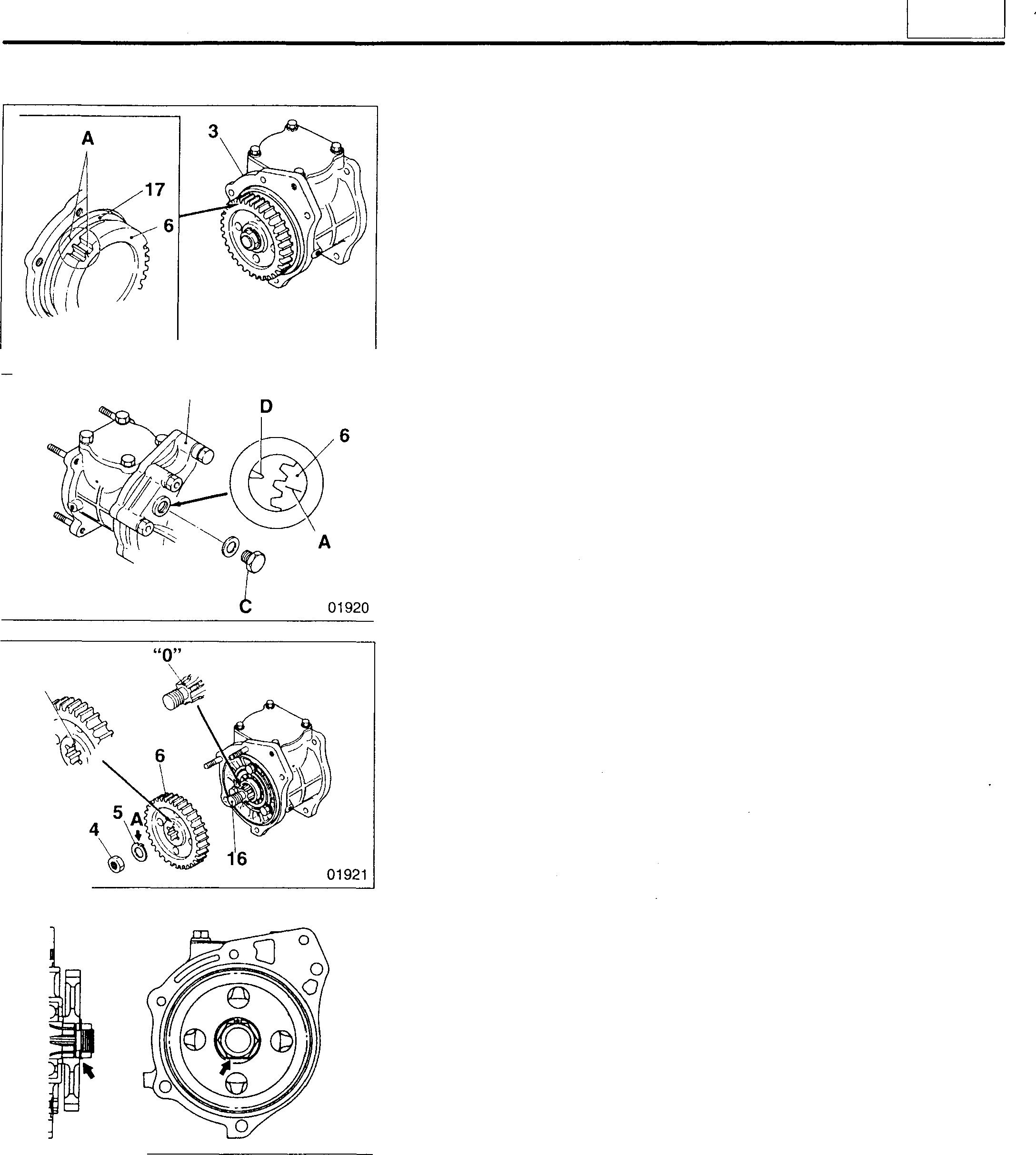
B
• Remove the plug C from the flywheel housing B, then check that the inscribedline A on the drive gear 6 isalignedwith the pointer D. If the line and pointer are not aligned, remove and refit the injection pump drive assembly.
Ci] to II] Installing drive gear
• Fit the drive gear 6 such that its "O" alignment mark is aligned with the "O"alignmentmarkonthepumpdriveshaft16.Then,fitthelockwasher 5 such that its notch A is aligned with the drive gear alignment mark, and tighten the nut 4 to the specified torque.
• Whentheassemblyiscomplete, bendthelockwasher5downonto the nut 4.
01919
"O" 01922 13
13-31
INJECTION PUMP DRIVE
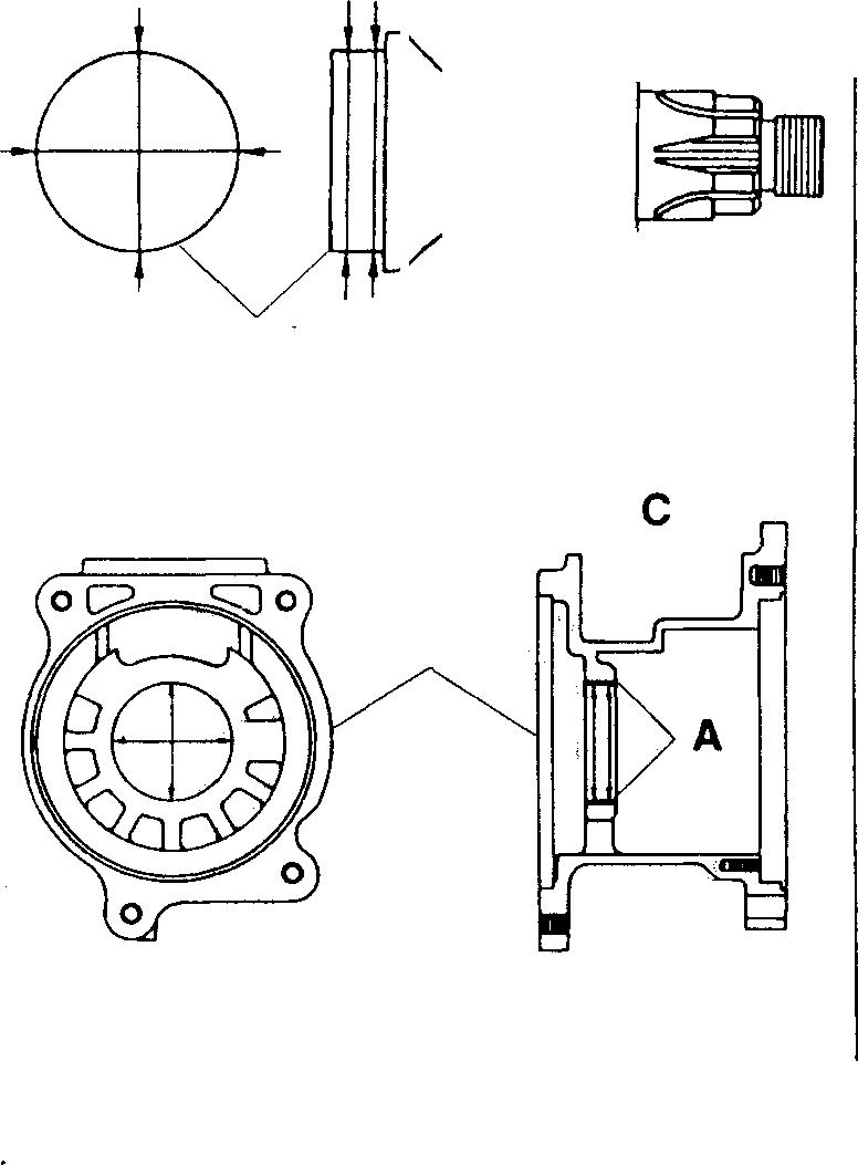
��Pumpdriveshaft-to-pumpdrivecaseclearance Iftheclearanceexceedsthespecifiedlimit, replacethepumpdrive case 17.
A: Bushing
B:Measurementdirections
C: Measurementpositions
B C 16 01923 B 17 02116 13-32
1a MEMO 13-33
INJECTION NOZZLE <1-spring Type>
@1--10 �8
• Inspectionbeforedisassembly [D P.13-35
•Disassemblysequence
Eyebolt
Fuelleak-off pipe
Injectionpipe
Bolt
Injectionnozzle assembly
Connector
Capnut
Adjustingscrew
Spring
0:Non-reusablepart
Repair kit : Nozzle Service Kit (for Zexel nozzlesonly)
•Assemblysequence
Reversethe orderof disassembly.
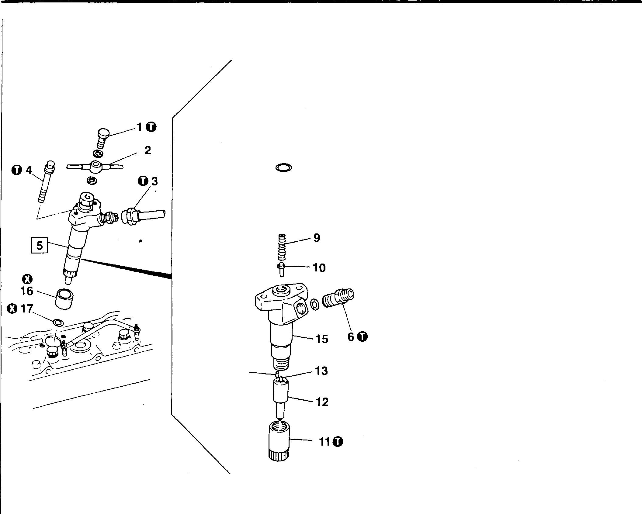
04555
WARNING_&------------------------
Tominimizetheriskoffire,wipeupanyspilledfuel.
CAUTION_&--------------------------
Underno circumstances changetheneedlevalve13andnozzle12combinationusedineachinjectionnozzle assembly5.
NOTE
• Clean off any carbon deposits before disassembling, reassembling, or adjusting the injection nozzle assembly 5. Before disassembly, check the pressure and shapeof the spray and inspect the assembly for fuel leaks. If no abnormality is apparent, do not commence disassembly.
• When fitting the injection nozzle assembly 5, tighten each of the two bolts 4 a little at a time.
14
1
2
3
4
5
6
7
8
9
10 Pushrod 11 Retainingnut 12 Nozzle 13 Needlevalve 14 Pin 15 Nozzle
16 Dustseal 17 Gasket
holder
13-34
Service standards Unit: mm Location Maintenanceitem
value Limit Remedy
5 Injectionpressure 17.7 MPa(180 kg/cm2} - Adjust
0 Tightening torques
Parts to be tightened
1 Eyebolt (fuelleak-off pipe mount- Zexel
to15(1.0to1.5}ing)
to20(1.5to2.0} -
3 Injectionpipeunion nut 25(2.5) -
4 Bolt(injection nozzle mounting) Zexel 15(1.5) -
� Special tools
Location Tool name and shape
- Nozzle Cleaning Tool
• Zexelpart number
to 78{6to8}
*105789-0010 Cleaningnozzles
♦ Service procedure
• Pre-disassembly inspection
Unit: mm
Fit the injectionnozzle assembly 5 onto the nozzle tester A ready for inspection.
NOTE
Before commencing inspection, operate the lever on the nozzle tester A two or three times to bleed all air out of the arrangement.
(1) Checking valve opening pressure
• Pushdowntheleveronthenozzletester A atarateof 1-2seconds perstroke. Thepressuregaugereadingwillgraduallyrise, thenthe needle will suddenly deflect. Note the pressure when the needle starts to deflect.
• If themeasurementisoutof specification, disassemble the nozzle, clean it, and make adjustments using the adjusting screw 8.
• If the measurement is still out of specification after adjustment, replace the injection nozzle assembly 5.
01910
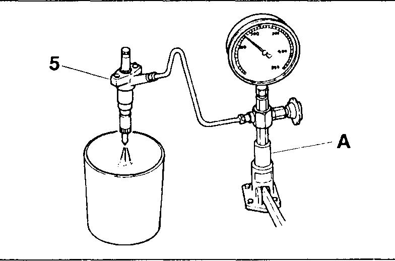
WARNING&_-----------
Do not touch the spray that comes out of the nozzle.
13
Standard
Location
Tightening
Remarks
Unit: N ·m {kgf·m}
torque
9.8
Nippondenso
15
6 Connector Zexel 69to 78(7
Nippondenso 59 to69(6
7 Cap nut 29
11 Retainingnut 59
-
Nippondenso 121014(1.2101.4) -
to8}
to7)
to39(3to4)
Part
No. Application
13-35
INJECTIONNOZZLE <1-spring Type>
(2) Inspecting spray condition
• PumptheleveronthenozzletesterAatarateofabout 1-2seconds per stroke, and maintain acontinuousspray.
B:Evensprayfromall fiveinjectionorifices (Good)
C:Evenandsymmetricalspray(Good)
D:Asymmetricalspray (Bad)
E:Branchedspray (Bad)
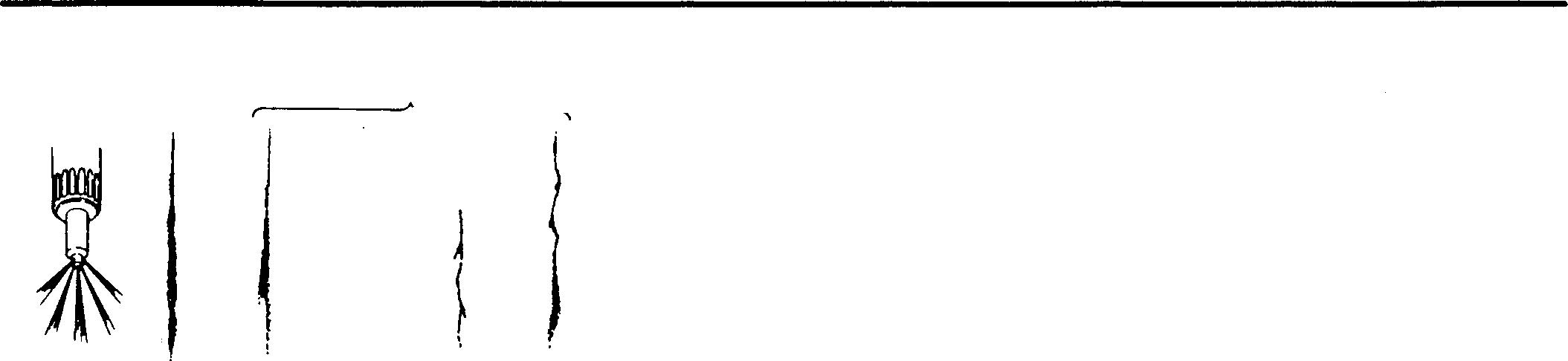
F:Thinspray (Bad)
G: Irregularspray (Bad)
• If the spray is unsatisfactory, disassemble and clean the injection nozzleassembly 5, theninspectthesprayagain. Ifthesprayisstill unsatisfactory, replacetheinjectionnozzleassembly 5.
• Checkthatnofueldripsfromthenozzleafterthesprayiscomplete.
WARNING_&------------
Do not touch the spray that comes out of the nozzle.
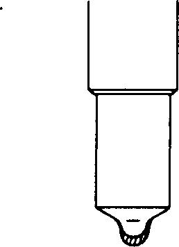
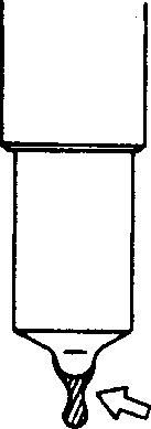
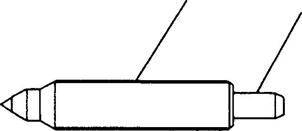
B

(3) Inspecting for leaks
• Slowlyincreasethenozzlepressureto1.96MPa{20kgf/cm2}below thespecifiedvalveopeningpressure. Maintainthispressurefor 1O secondsandcheckthatnofueldripsfrom the end ofthenozzle.
• If the injection nozzle assembly 5 appears defective, disassemble andclean it, then inspect it again. If theinjection nozzle assembly 5 stillappearsdefective, itmust bereplaced.
[I] Injection nozzle assembly
[Disassembly]
CAUTION_&--------------
• Do not touch the sliding parts A of the needle valve 7.
• Do not change the needle valve 13 and nozzle 12 combination on each cylinder.
[Cleaning]
Washtheneedlevalve 13 andnozzle 12 ingasoil,thenusethe�CleaningToolSettoremoveanycarbondepositsinaccordancewiththefollowingprocedure.
• Removecarbonfromtheendoftheneedlevalve 13usingtheCleaning Barofthe� Cleaning Tool Set.
CAUTION_&-------------
Do not use a wire brush or any hard metallic object for cleaning.
Good ,----"----, B C Good 13-36 � J D E A Bad t F G 06931 Bad 05388 13 04744
04556
• Remove carbon from the injection orifice of the nozzle 12 using the Needle Cleaner ofthe I&] Cleaning Tool Set. Insert the Needle Cleaner and rotate it to dislodge the carbon.
• Clean the seat of the nozzle 12 using the Cleaning Scraper of the I&] Cleaning Tool Set.
• Toremoveburnedandhardenedcarbon, use FUSOCarbon Remover.
[Inspection]
• Washthe needlevalve 13andnozzle 12 ingasoil, thenfit them together.
• Pull up the needle valve 13 by approximately 1/3 of its entire stroke, then check that it drops under its own weight. Repeat this test several times, turning the needle valve each time.
• If theneedlevalve 13doesnotdrop asrequired, washit in gasoiland carryoutthistestagain. Iftheneedlevalveisstilldefective,replacethe needle valve and nozzle 12 as a set.

NOTE
Whenever a nozzle 12 isreplaced, the nozzle and needle valve 13 must be replaced as a set using Nozzle Service Kit. (This applies to Zexel products only.)
01894 13 01911 13
13-37
Pages 13-38 to 13-53 are deleted as they are not in use.
COOLING SPECIFICATIONS ............................• • •...•.......•. 2 STRUCTURE AND OPERATION ............................... 3 TROUBLESHOOTING .................................•....... 5
INSPECTION AND ADJUSTMENT • Replacing Coolant and Cleaning CoolantSystem ..................... 6 • Air Bleeding ofCooling System ...................................... 8 • Gas LeakTesting ................................................... 8 RADIATOR ..... ......... ........ ............... ............ . 10 COOLING FAN AND V-BELT................................... 12 WATER PUMP ............................................... 16 THERMOSTAT ............................................... 20 14 1: 14-1
GROUP 14
ON-VEHICLE
SPECIFICATIONS
Item
Cooling system
Water pump type
Thermostat type
Automaticcoolingfancouplingtype
Radiatortype
Coolantcapacity dm3 {L}
(enginemain body only)
Specifications
Forced water circulation type
Belt-driven involute type
Wax pellet, bottom bypass type (withjiggle valve)
Constantcontroltype
Tubeandcorrugated fintype
13(13}
14-2
STRUCTURE AND OPERATION
MITSUBISHI 6D16TLEA Cooling System (Water Flow)
Mitsubishi 6D16TLEA Tadano Crane Water Pump
<Withoutcover>
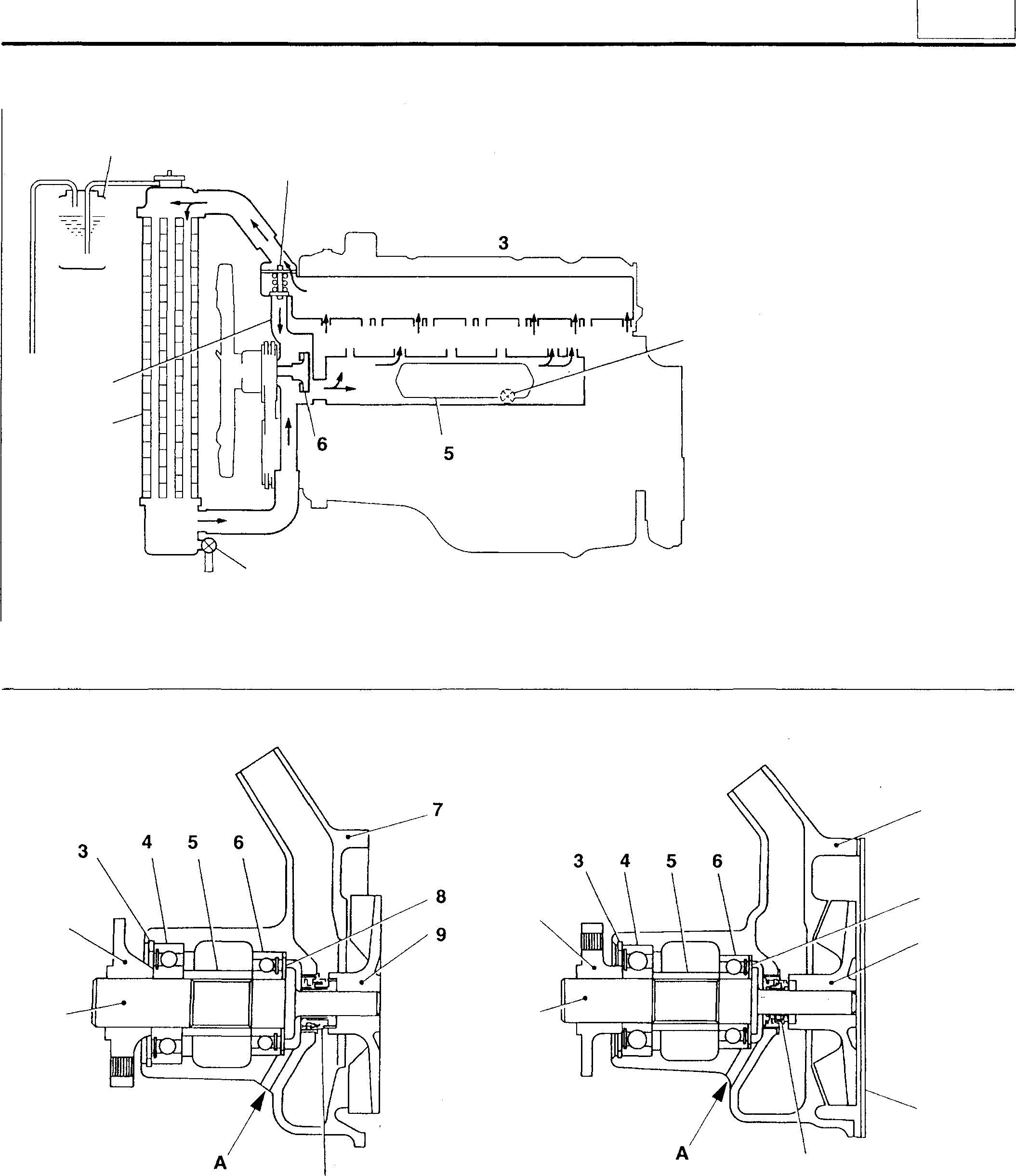
9 8 1
2 1 1 Water
2 Flange 3
4 Bearing 5 Spacer 6 Bearing 7 Water pump case 2 7 11 16934 1 <With cover> 2 8 Washer 9 Impeller 10 Cover 11 Unit seal A: Drain hole 4 16951 1 Reservoir tank 2 Thermostat 3 Cylinder head 4 Drain plug 5 Oil cooler 6 Water pump 7 Drain cock 8 Radiator 9 Bypass hose 7 8 9 10 11 14 16935 14-3 Mitsubishi 6D16TLEA
parts contact: email: engineparts2@gmail.com Phone: 269 673 1638 Text: 269 760 8652
pump shaft
Snap ring
engine
STRUCTURE AND OPERATION
Mitsubishi 6D16TLEA Tadano Crane Thermostat
1 Thermostatcover
2 Thermostat
3 Thermostatcase
A:Toradiator
B: Withlowcoolanttemperature
C: Withhighcoolanttemperature
D: Fromcylinderhead
E:Towaterpump
Thermostat 2 isabottombypasstypethatuseswax-charged pelletsasitsregulatingelement.Asthewaxchangesfromsolid toliquidinlinewithtemperatureincreases,thetotalwaxvolume changes.Asaresult,thepositionofthevalve, changedbythe coolanttemperature,regulatestheflowofcoolanttotheradiator andwaterpump(bypassside)andcontrolsthecoolanttemperature.
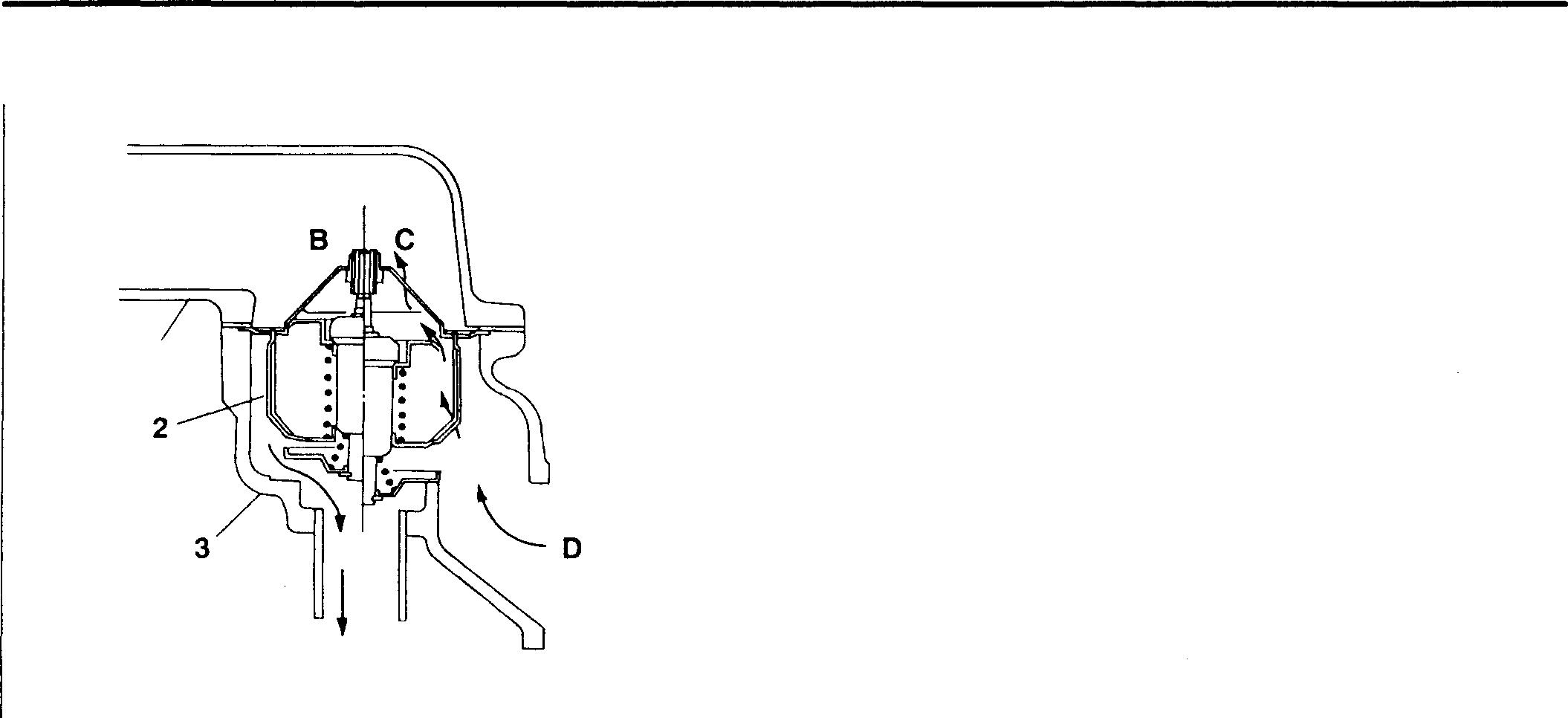
Cooling System Electric Circuit 1 2 3


• Water temperature gauge circuit
1 Fusebox
2 Watertemperaturegauge
3 Watertemperaturesensor
Inthiscircuit,thewatertemperatureisdeterminedaccordingto theelectricalresistanceofwatertemperaturesensor3anddisplayedonwatertemperaturegauge 2.
Mitsubishi 6D16TLEA engine parts contact: email: engineparts2@gmail.com
Phone: 269 673 1638
Text: 269 760 8652
A1
E
06361 cf'\s)-1-�f------+-'I�----+--I�-t=16952 14-4
TROUBLESHOOTING
14 Symptoms .£ 0 c (/l u (/l Remarks i: .2 � c (/l Q) Cll C: 0 :=:.- (/l 0) o 0 C: (.) C: .£ � cil Q) 0 > Q) 0 E "iii � .... 0 Q) Q) Q) C: (.) > > .0 Possible causes 0 0 c:x: w V-belt Loose or damaged 0 0 Excessive tension 0 Oil on belt 0 Water pump Water pump fitted poorly 0 0 Gasket defective 0 0 Bearing defective 0 0 Impeller defective 0 Unit seal defective 0 0 Loose fit between shaft and flange and/or shaft and im- 0 0 peller Thermostat Case fitted poorly 0 0 Gasket defective 0 0 Valve opening temperature too high; valve remains 0 closed Valve opening temperature too low; valve remains open 0 Water leaking from water temperature sensor 0 0 Radiator Space between core and fins clogged 0 Core cracked and/or separation of soldered joints 0 0 Pressure cap not sufficiently airtight 0 Cooling fan Fan shroud fitted poorly 0 0 Automatic cooling Bearing defective 0 0 fan coupling Bimetal damaged 0 Bimetal contaminated with foreign particles 0 0 Silicon oil leaking 0 0 Oil cooler Oil cooler fitted poorly 0 0 OJ Gr 12 Gasket defective 0 0 Cylinder head Cylinder head fitted poorly 0 0 OJ Gr 11 Gasket defective 0 0 Coolant quantity insufficient and/or coolant dirty 0 Coolant passages dirty and/or clogged 0 Hoses fitted poorly 0 0 Ambient temperature extremely low 0 14-5
ON-VEHICLE INSPECTION AND ADJUSTMENT
Replacing Coolant and Cleaning Coolant System
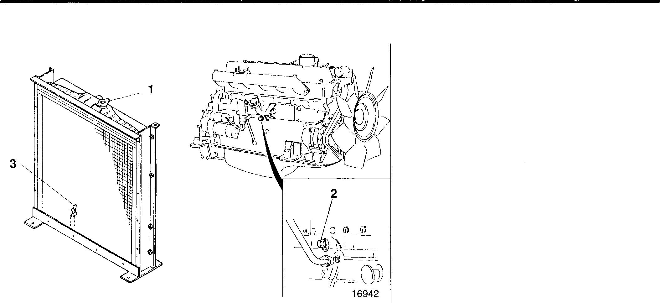
16941
0 Tightening torques
Location Parts to be tightened
2 Crankcase drain plug
1 Pressure cap
2 Crankcase drain plug
3 Radiator drain cock
Tightening torque 115 (12}
Unit: N ·m {kgf ·m}
Remarks -
Using the radiator for extended periodswithout cleaning the cooling system willcause overheating since rust andscaledeposits will accumulate. The cooling system must be cleaned periodically.
• Draining coolant
Before draining the coolant, loosen pressure cap 1 to reduce the pressure in the cooling system.
WARNING_&.-------------------------
• To avoid being scalded, ensure that the coolant has cooled sufficiently before draining it out.
• Unless care is exercised, opening pressure cap 1 when the coolant is hot can cause the coolant to spray out. Cover the pressure cap with a cloth, and loosen the cap slowly to bleed off the pressure before opening it fully.
• Cleaning procedure
• Run the engine and keep the coolant at a temperature of approximately 90°C sothat the thermostat valve remains open and the coolant continues to circulate in the radiator.
• To increase the coolant temperature quickly, cover the front of the radiator with cardboard or a similar material.
• If cleaning is carried out after a large amount of rust has accumulated, the radiator may start to leak. Carefully examine the radiator for leaks after cleaning the cooling system.
• Soft water to be used should have the following properties.
CAUTION_&.--------------------------
Do not use hard water as it causes scale and rust.
Required propertiies of soft water
Total hardness
300 ppm or less
Sulfate SO4 100 ppm or less
Total dissolved solids 500 ppm or less
pH 6 to 8
Chloride c1- 100 ppm or less - -
14-6
Method of cleaning the cooling system depends onits condition.
• Ordinary condition
Cleaning using water
e Extremely dirty coolant
• Clogged radiator
Cleaning using Radipet 7or equivalent
Drain the coolant.
(Workprocedure)
Drain the water and the solution.
r ►
Fill with soft water (boiled preferably).
Keep the water temperature at 90°C and let engine idle for 10 minutes.
' I Drain the water. i i
If the drained water is clear, cleaning has been successful.
If it is still muddy, repeat the procedure.
Make a solution of FUSO Radiator Cleaner (Radipet 7 or equivalent) at a rate of 5 to 10% to the total volume of coolant.
Fill the radiator with the solution.
Keep the solution temperatureat 90°C andletthe engine idle for 30 minutes.
CAUTIONL[s--------
Besure toallow theengineto idle for 30 minutes only. Circulating the solution in the system for more than an hour might cause the system to breakdown.
L _J
NOTE
• After cleaning with solution, fill with coolant as quickly as possible.
• To prevent freezing of the coolant andcorrosion of the cooling system, use specified coolant solution of FUSO Diesel Long Life Coolant, FUSOAntifreezeor Radiator Antirust (Radipet 9). (See the Owner's Handbook for use of these materials.)
14
14-7
ON-VEHICLE INSPECTION AND ADJUSTMENT
Air Bleeding of Cooling System
• Removethepressurecap. Keepingthecoolanttemperatureat90°C, lettheengineidleuntilthecoolingsystemiscompletelybled ofair. Whiletheengineis idling, keeptheheatercontroller's adjustmentleveratitsmaximum-temperature positionsothat coolantflowsfreelyin the heaterpiping.
• After bleeding thecoolingsystem ofair, addcoolantto the radiatorand reservoir tankas required.
Gas Leak Testing
Thepresenceofairorexhaustgasinthecoolantincreasescorrosionandrustinthecoolingsystem.Checkforairorexhaust gas in the coolant usingthefollowing procedure:
• Remove pressurecap 1.
WARNING&--------------
Make sure the coolant is sufficiently cool before loosening the pressure cap. If the coolant is hot, it will spray out.
• Run the engineuntilthecoolanttemperaturereaches approximately 90°C.
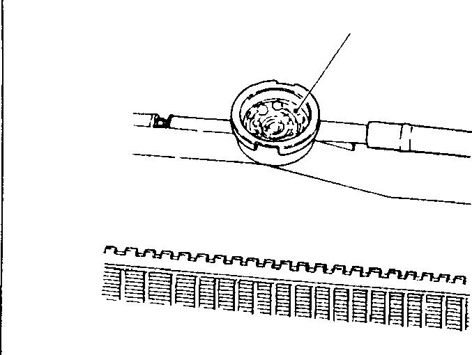
• IfbubblesAappearcontinuously,thereisairorexhaustgasinthecoolant.
• Ifthecoolantcontainsair, thecylinderheadbolts, waterpumpmounting bolts, or hose connections maybeloose. Alternatively, the hoses may bedamaged.
• Ifthecoolantcontainsexhaustgas,itispossiblethatthecylinderhead gasketis damagedor that thecylinder headiscracked.
A ------------:---.._____00187 14-8
14 MEMO 14-9
RADIATOR
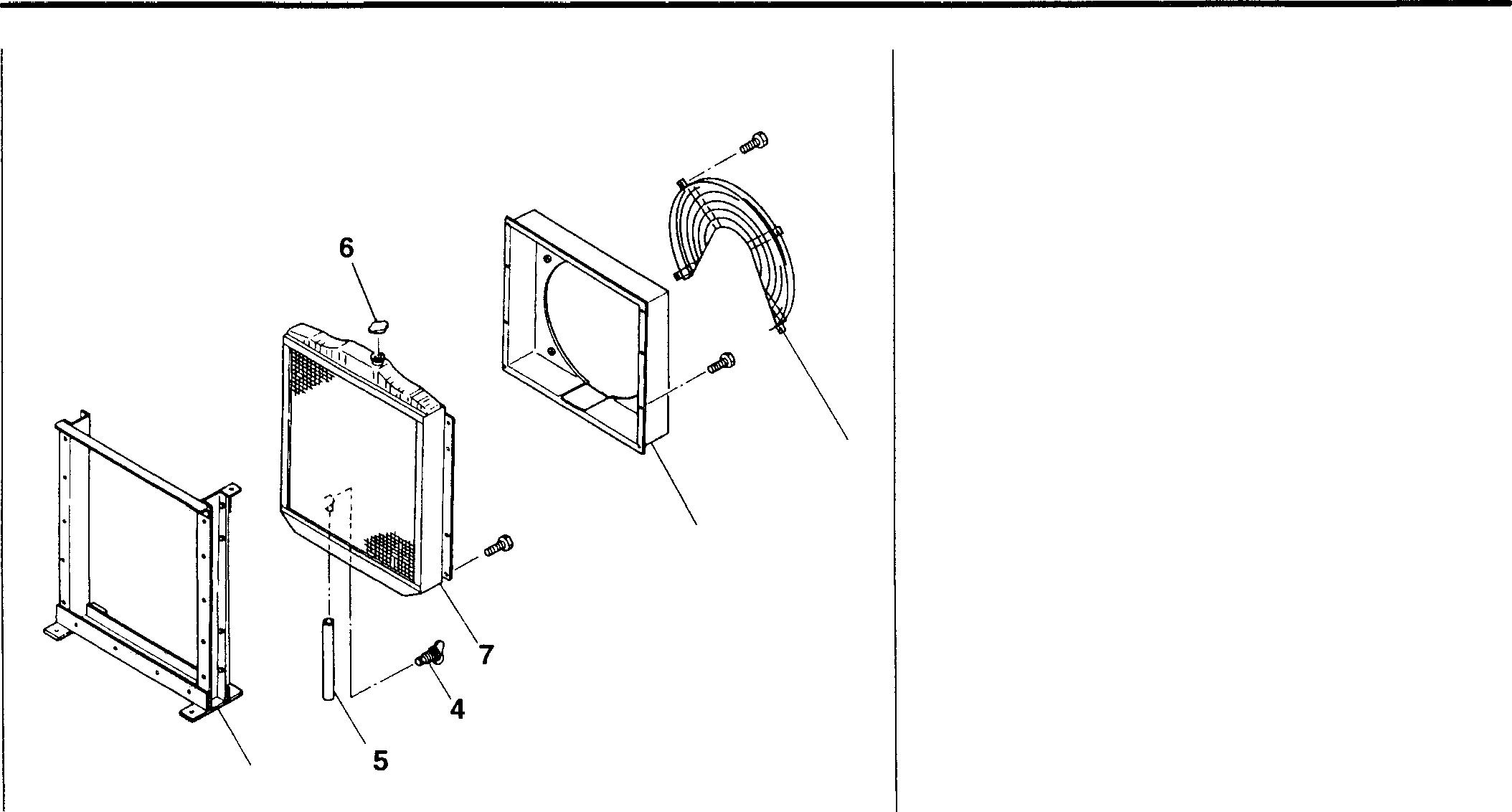
3
Service standards
Location Maintenance item
6 Pressure valve opening pressure
7 Radiatorairleakage
2
• Disassembly sequence
1 Wirenet
2 Shroud
3 Frame
4 Drain cock
5 Drain hose
6 Pressurecap
7 Radiator
• Assembly sequence Reversethe order of disassembly.
Standardvalue Limit
69±15 kPa (0.7±0.15 kg/cm2}0ccRemedy Replace Corrector
(with airpressure of 150kPa(1.5 kgf/cm2}) replace
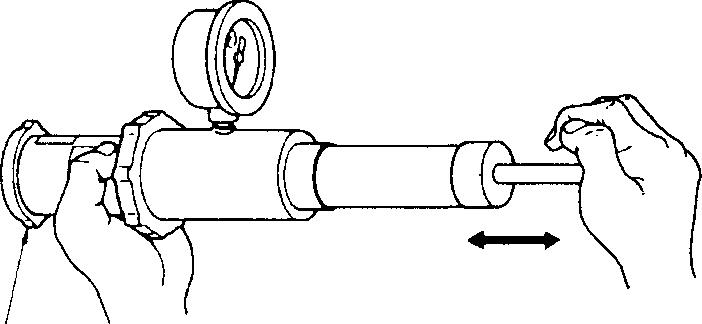
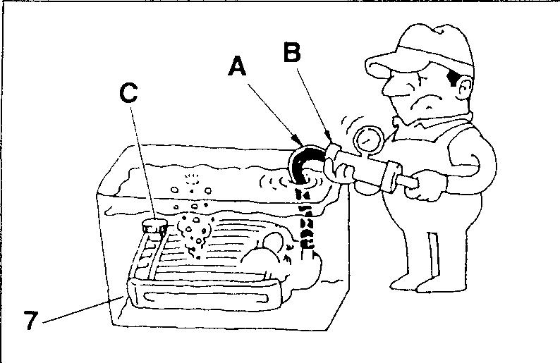
♦ Service procedure
W Pressure cap inspection
Measure the pressure valve's opening pressure. If the measurement doesnot conform with the standard value, replace pressure cap 6.
[z] Radiator inspection
• Fit hose A and radiator captester B to the radiator upper tank.
• FitplugCtothelowertank,thenimmersetheradiatorinatankofwater.
• Usingradiatorcaptester B, applythespecifiedairpressureof150kPa {1.5 kgf/cm2}, and check for air leakage.
• If air leakage is apparent, correct orreplaceradiator 7.
1 16943
6 00194 07386 14-10
14 MEMO 14-11
• Disassembly sequence
1 V-belt
2 Automatic cooling fan coupling
3 Cooling fan
4 Spacer
5 Water pump pulley
*: Water pump assembly [O P.14-16
• Assemblysequence Reverse the order of disassembly.
CAUTION_&.-------
• Automatic cooling fan coupling 2 is an integrated unit and cannot be disassembled.Ifanyfaultisapparent,replace the whole assembly.
• When replacing V-belts 1, be sure to replacethemasasettomaintaineventension between them.
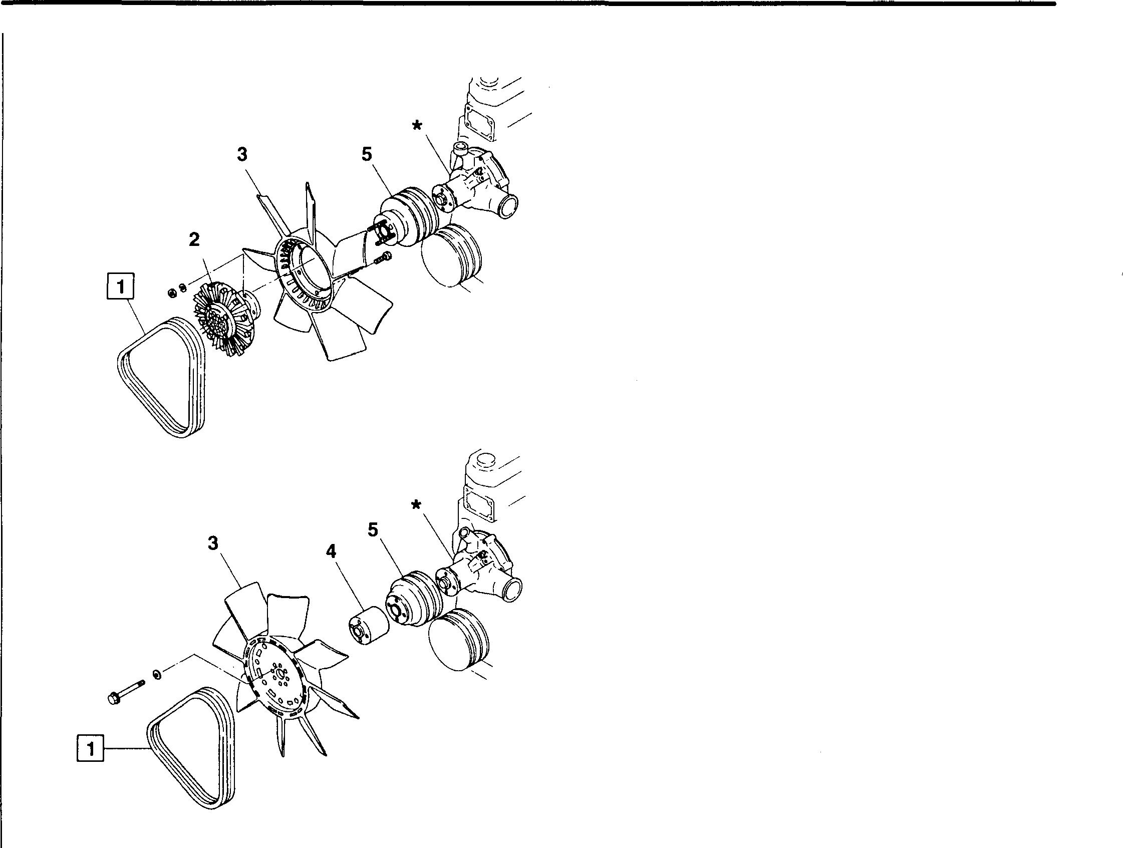
Mitsubishi 6D16TLEA engine parts contact: email: engineparts2@gmail.com
Phone: 269 673 1638
Text: 269 760 8652
Special tools
MH062345 V-belt tensionmeasurement
MITSUBISHI
TLEA TADANO
ANE
Service
Location Maintenance item
�
Location Tool name and shape I Belt tension = 1 gauge 03612 14-12 16946 16947
6D16
CR
COOLING FAN & VBELT
standards
1 V-belt tension
Unit: mm Standardvalue Limit Remedy 10 to 15 - Adjust Part No. Application
♦ Service procedure [I] V-belt
[Inspection]
Applyforceofapproximately98 N {10kgf}tothecenteroftheV-belt 1 and measure the extent of V-belt deflection A.
B: Alternator pulley
C: Water pump pulley
D: Crankshaft pulley
• Use of belt tension gauge
• Setupper O-ring E of� belttensiongaugeto 8 N {10 kgf} (push load) on scale F.
• SetlowerO-ringG of�belttensiongaugetotheV-belt'scorrectmaximum deflection value on scale H.
• Applythe� belttensiongaugetothecenter of V-belt 1 andpushuntil O-ring E reaches the flange K.
• Measure the extent of V-belt 1 deflection A. If the measurement does notconformwiththestandardvalue, adjusttheV-beltasshownbelow.
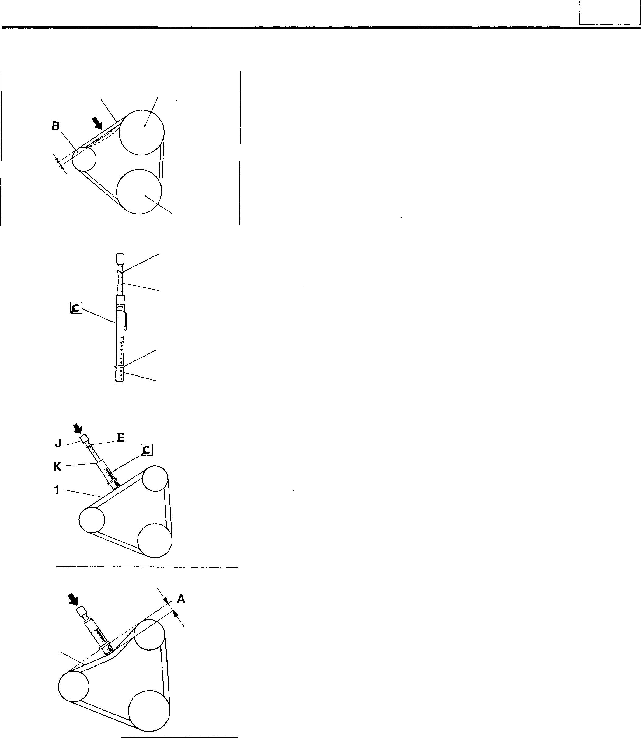
1 C A D 16948 E F G H 03613 03614 1 03615
14
14-13
COOLING FAN AND V-BELT
(Adjustment]
Adjustthe V-belttension as follows:
• Loosenalternatormountingbolts L (2places)andadjusttheV-belttension by moving alternator M tothe left orright.
• Whentheadjustmentiscomplete, tightentheboltsandnutssecurely.
CAUTION_&--------------
• Excessive tension in V-belt 1 may damage the belt and related bearings.
• Be sure to replace the V-belts 1 as a set to maintain even tension between them.
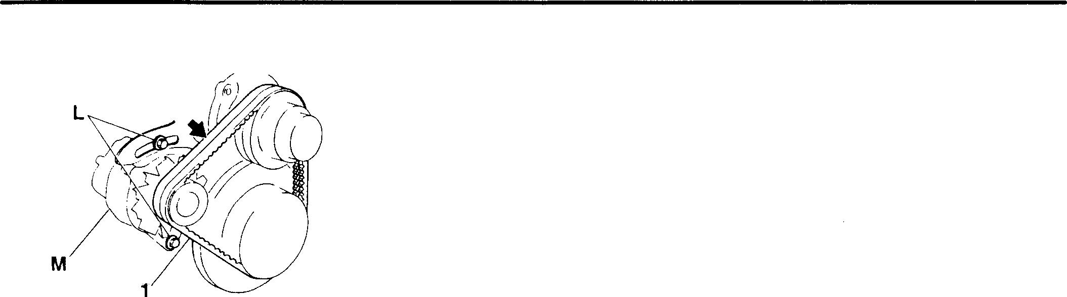
00203
• Keep V-belt 1 freeof oil. If the beltbecomes oily, it will slip, resulting in overheating of the engine and insufficient charging of the battery.
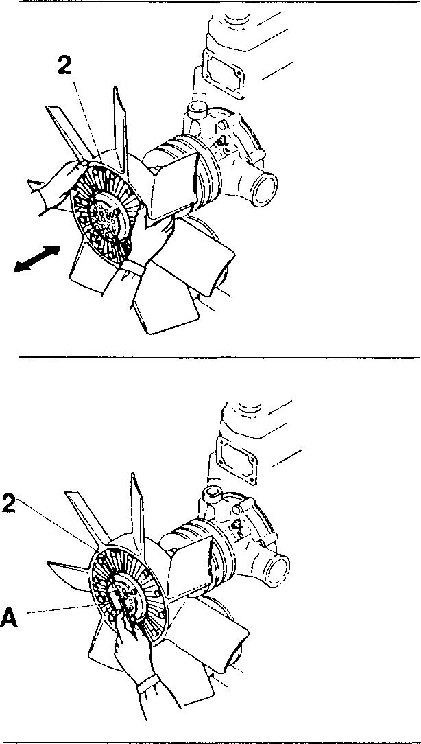
[I] Automatic cooling fan coupling
[Inspection]
Inspectautomaticcoolingfancoupling 2 inaccordancewiththefollowing procedure. If any defect is evident, replace theunit.
• Checkfor leakage of oil fromthe couplingbody.
• Rotateautomaticcoolingfancoupling2byhandandcheckforirregular movement or abnormal noisecausedby a defect in the bearing.
• Check for excessive axial play in automatic cooling fan coupling 2 when the engine is cool.
[Cleaning]
Ifany foreignparticleshaveadheredtobimetalA, brushthemoffgently.
16949
14-14
16950
I 14 I MEMO 14-15
UBISHI 6D16TLEA TADANO CRANE WATER PUMP
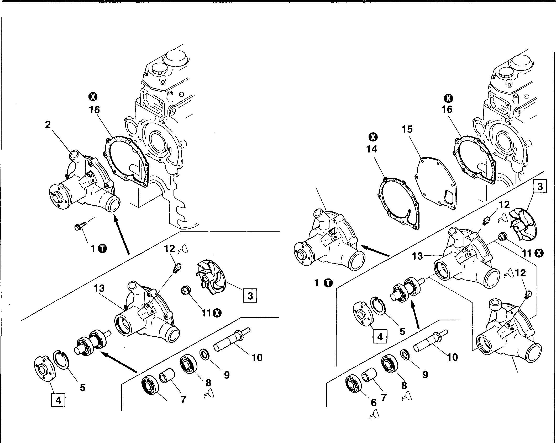
• Assembly sequence 16--+15--+14--+2--+1
2 : 113 ...... 12 ----��10--+9--+8--+7--+6 j
• Inspection after assembly lI] P.14-18
Mitsubishi 6D16TLEA engine parts contact: email: engineparts2@gmail.com Phone: 269 673 1638
269 760 8652
MITS
cover> • Disassembly sequence 1 Bolt 2 Waterpump assembly 3 Impeller 4 Flange 5 Snapring 6 Bearing 7 Spacer 8 Bearing 9 Washer
<Without
14-16 6 � 16925 <With cover> 2 10 Water pumpshaft 11 Unitseal 12 Greasenipple 13 Water pump case 14 Gasket (pumpwith cover) 15 Cover (pumpwith cover) 16 Gasket 0:Non-reusablepart 13 <6D16-TC> 16926
Text:
Service standards
Location Maintenance item
3,10 Impeller-to-waterpump shaftinterference
4,10 Flange-to-waterpump shaftinterference
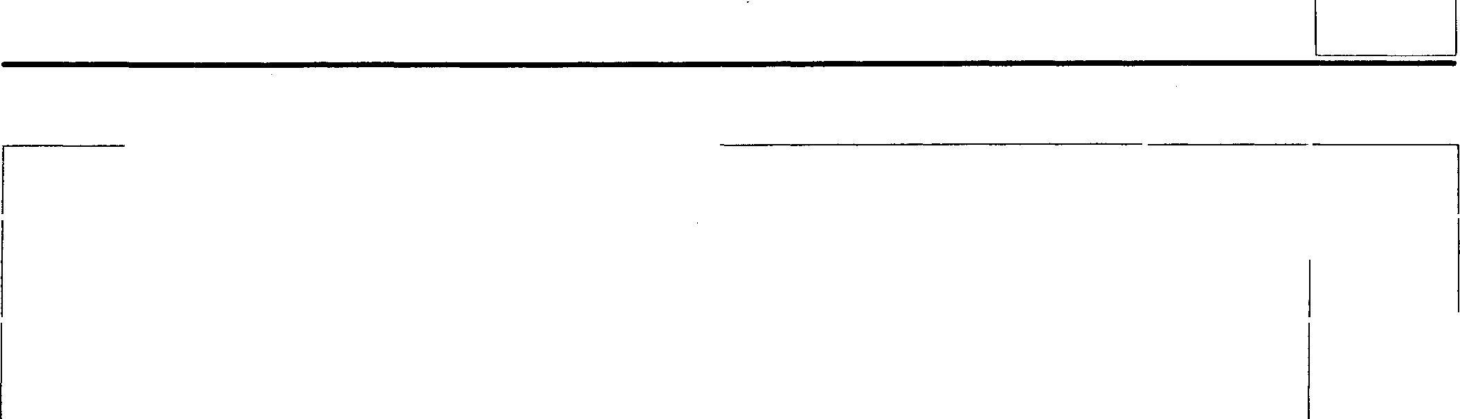
0 Tighteningtorque
Location Parts to be tightened
1 Bolt (waterpumpassemblymounting)
� Lubricants and sealant
Location Points of application
6,8 Bearings
11 Unit seal outerperiphery 12 Grease nipple
� Specialtools
Location Tool name and shape
3
Impeller puller
Standardvalue Limit Remedy (Basicdiameter in [ ])
[13] 0.03 to 0.06 - Reassemblyallowed onlytwice
[26] 0.05to0.08 - Reassemblyallowed onlytwice
9.8 (1.0}
Kinds
Wheelbearinggrease
required [NLGI No. 2 (Lisoap)]
THREEBOND 1102
Wheelbearinggrease
g [NLGI No. 2 (Lisoap)]
Part No. Application MH061417 Removingimpeller
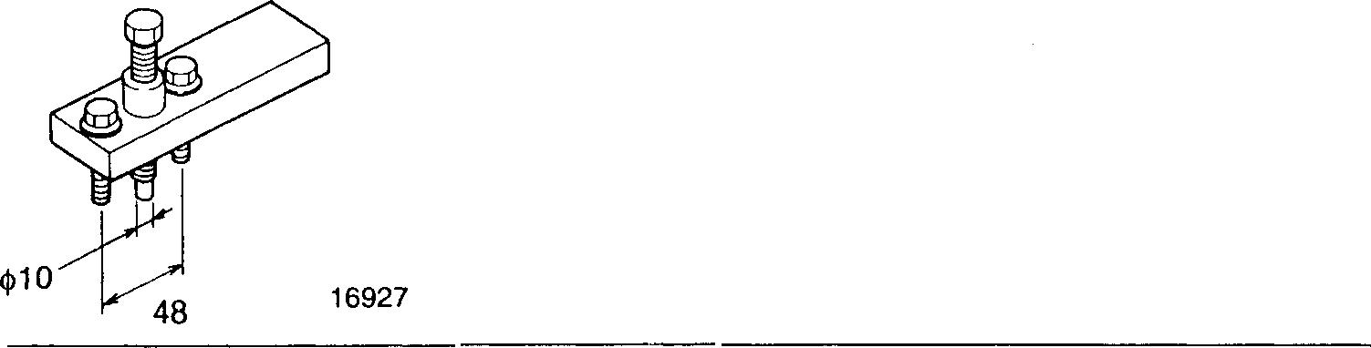
14 Unit:
mm
Unit: N·m {kgf·m}
Remarks
Tighteningtorque
-
Quantity
As
As
required
60
Unit: mm
14-17
WATER PUMP
♦ Service procedure
• Inspection after assembly
• Afterassembly,rotateflange4byhandandcheckthatitturnssmoothly withouthindrance.
• Iftheflangedoesnotturnsmoothly,disassembleandinspectthewater pump again.
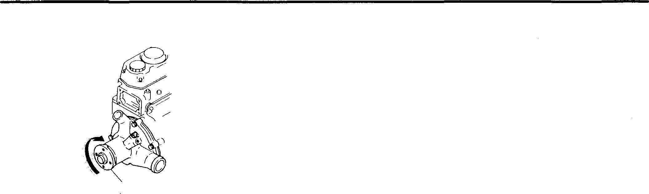
3
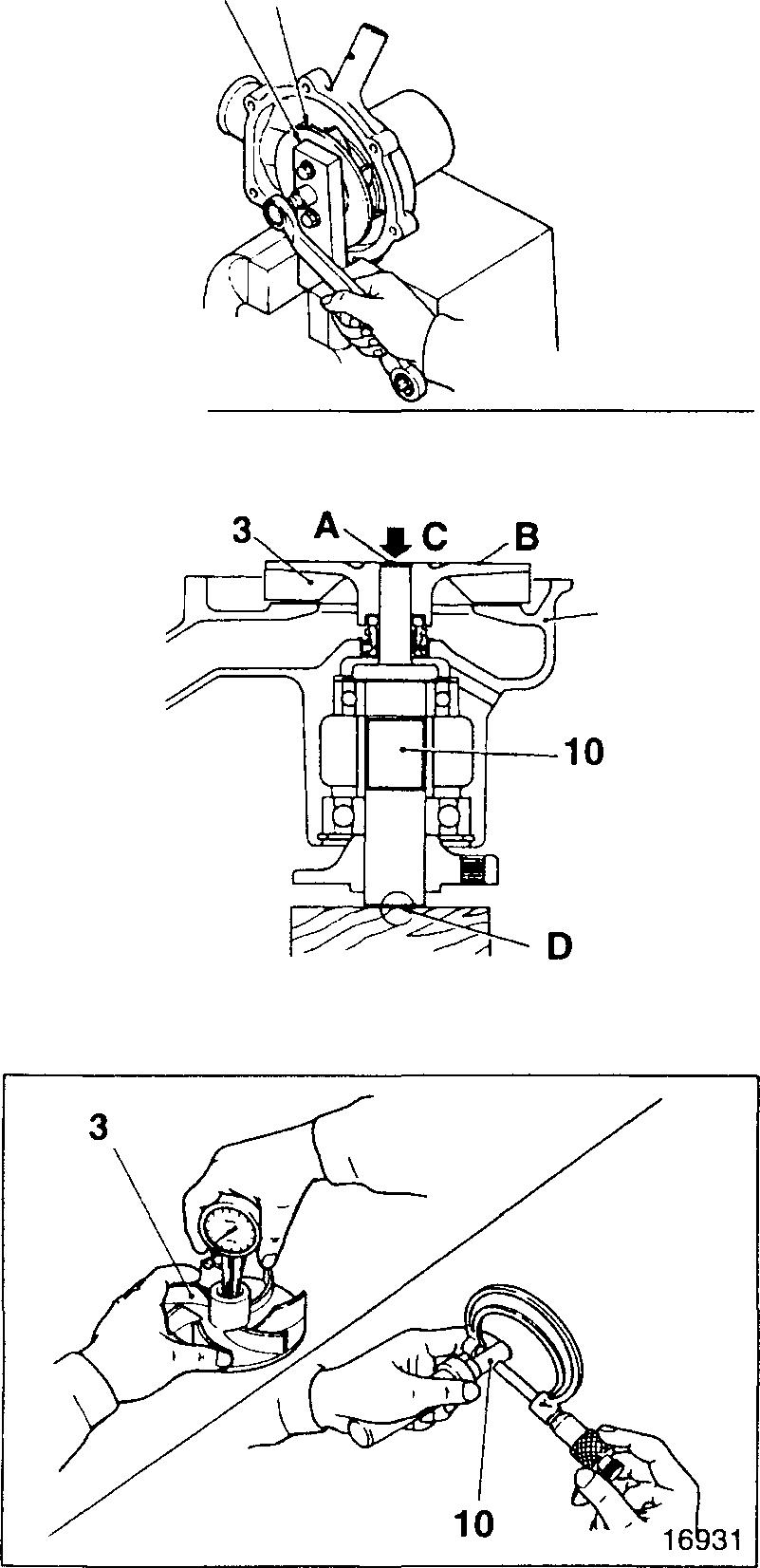
W Impeller [Removal]
[Press-fitting]
Press-fitimpeller3 untilits endface B isinline with end face A ofwater pumpshaft 10.
C: Press NOTE
Press-fittheimpellersuchthatflange side D of waterpumpshaft 10 is the load receivingsurface.
W [IQ] Impeller-to-water pump shaft interference
Ifthemeasurementdoesnotconformwiththestandardvalue,replacethe defectivepart(s).
CAUTION,&--------------
Even if the standard value is satisfied, reassembly must not be carried out more than twice.
4
13
16928 1£]
16929
14-18
16930
@] Flange
[Removal]
A:Gear puller
[Press-fitting]
Withaloadof9,81ON{4,000kgf},press-fitflange4untilittouchesbearing 6.
B: Press
C: Cylindrical jig
@] [!QI Flange-to-water pump shaft interference
Ifthemeasurementdoesnotconformwiththestandardvalue,replacethe defectivepart(s).
CAUTION&,--------------
Even if the standard value is satisfied, reassembly must not be carried out more than twice.
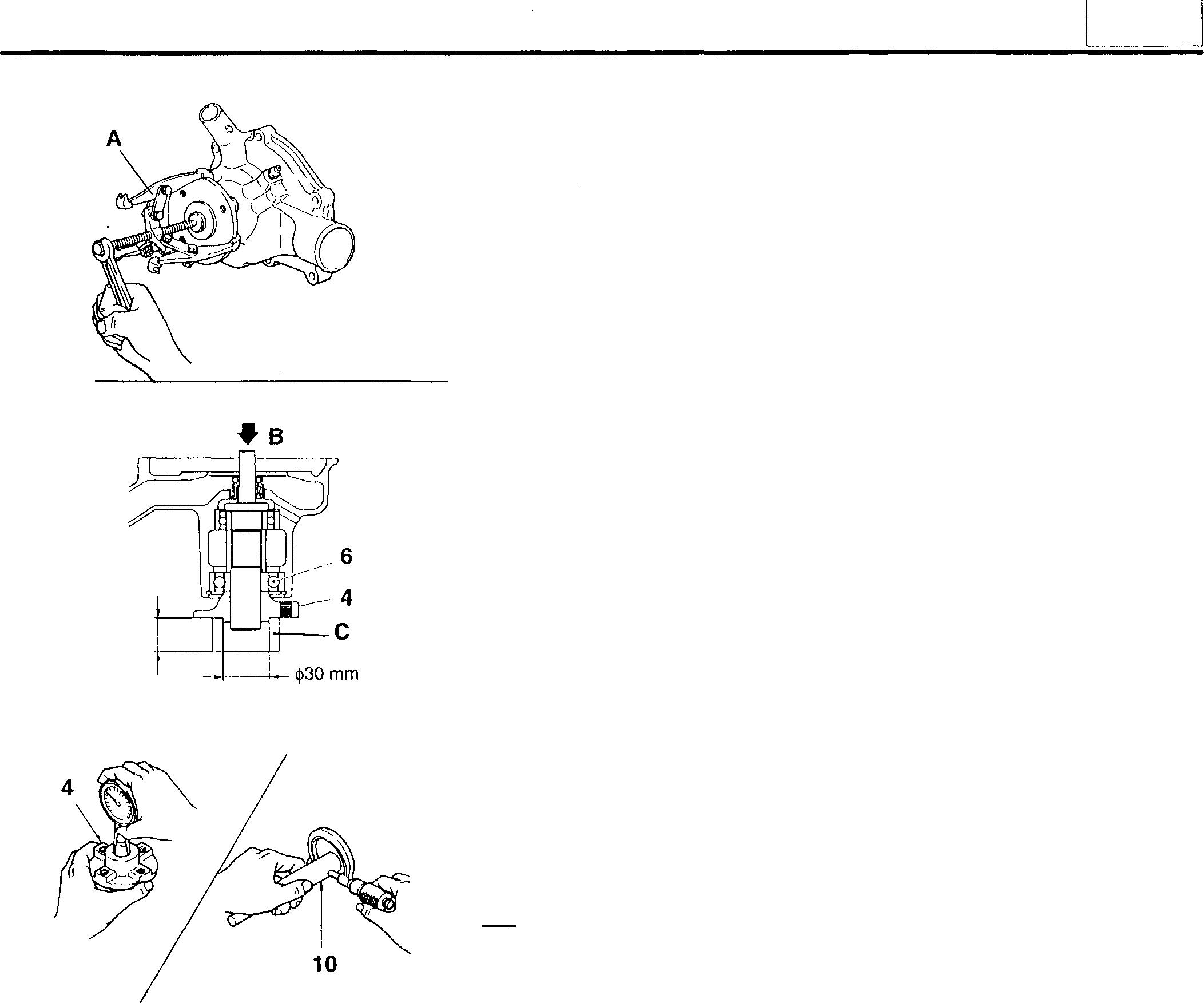
16932 20 mm or more 16933 00212
14
14-19
THERMOSTATHOUSING-TEMPERATORSENSOR-THERMOSTAT
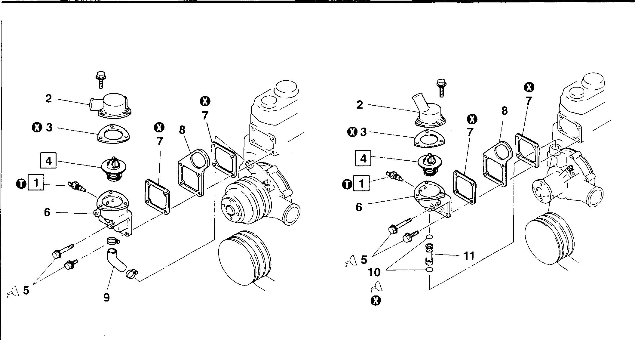
•
Do not remove thermostat case 6 and front hanger 8 unless they are leaking water or otherwise defective.
• Assembly sequence
Reverse the order of disassembly.
1 Water temperature sensor 2 Thermostat cover 3 Gasket 4 Thermostat 5 Bolt 6 Thermostat case 7 Gasket
16944 8 Front hanger 9 Bypass hose 10 O-ring 11 Joint 0: Non-reusable part 16945
Disassembly sequence
NOTE
Service
Location Maintenance item Standard value Limit Remedy 1 Water temperature sensor 50°C (136 n) - Replace resistance (Between termi- 80°C 48 ± s nnal CD and body) 100°c 27.2 ± 2 n4 Thermostat Valve opening 76.s ± 2°c - Replace temperature 4 Thermostat Valve lift/temperature 10 mm or more at 90°C14-20 MITSUBISHI 6D16TLEA
Mitsubishi 6D16TLEA engine parts contact: email: engineparts2@gmail.com Phone: 269 673 1638 Text: 269 760 8652
standards
TADANO CRANE
0
Tightening torque
Location Parts to be tightened
Unit: N ·m {kgf · m}
Tightening torque Remarks
1 Watertemperature sensor 34± 6.9 {3.5 ±0.7) -
� Lubricantand sealant
Location Points of application Kinds Quantity
5 10
Threadsofbolts (thermostatcasemounting)
Peripheryof O-ring
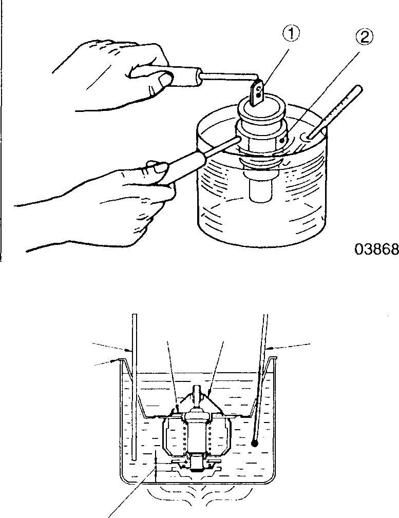
THREEBOND 2302 As required
Soapywater As required
♦ Service procedure
OJ Water temperature sensor inspection
• Place water temperature sensor 1 in a container of engine oil.
• Heat the oil until it reaches the specified temperatures. Stir the oil to ensure that it heats up evenly.
• Measure the resistance between terminal G) and body(� of the water temperature sensor.
• If the measurements donotconform with the specified values, replace the water temperature sensor 1.
[!] Thermostat inspection
Place the thermostat in a container of water. While stirring the water with arodAtoensurethatitisheatedevenly, carry outthefollowinginspection procedure. Ifthemeasurementsdo notconform withthestandardvalue!,, replace the thermostat 4.
(1) Valve opening temperature
• Support thermostat 4 with wire E to keep it away from heat source D.
• Gradually heatthewateruntil itreachesthevalveopening temperature.
• Maintain this temperature for 5 minutes and check that valve B is open.
• When the watertemperature drops below 65°C, check that valve B is completely closed.
C: Thermometer
(2) Valve lift
Heat the water to slightly higher than the valve opening temperature. With valve B fully open, maintainthis water temperature for5 minutes. Measure the extent of valve lift F.
14
A E
F
B 4 C n-----0
00218
14-21
GROUP 15 INTAKE AND
SPECIFICATIONS . . . . . . . . . . . . . . . . . . . . . . . . . . . . . . . . . . . . . . . . . . . . 2 STRUCTURE AND OPERATION . . . . . . . . . . . . . . . . . . . . . . . . . . . . . . . 3 TROUBLESHOOTING . . . . . . . . . . . . . . . . . . . . . . . . . . . . . . . . . . . . . . . . . 9 ON-VEHICLE INSPECTION AND ADJUSTMENT • Inspection of Dust Indicator . . . . . . . . . . . . . . . . . . . . . . . . . . . . . . . 10 AIR CLEANER <FHG, FWG>••••••••••••••••••••••••••••••••••••••••••••••••• 12 <FTG>•••••••••••••••••••••••••••••••••••••••••••••••••••••• 16 <Cartridge> ••••••••••••••••••••••••••••••••••••••••••••••••• 19 TURBOCHARGER ••••••••••••••••••.••••••••••••••••••••••••••• ••••••••••••30 INTERCOOLER < 6D16-TLEA > . . . . . . . . . . . . . . . . . . . . . . . . . . . . . . . . . . . . . . . . . . . . . . . . . . 52 INTAKE MANIFOLD <6D16-TLEA> ••••••••••••••••••••••••••••••••••••••••••••••••••58 EXHAUST MANIFOLD 6D16-TLEA•••••••••••••••••••••••••••••••••.••• 61 6D16-TLEA•.••••••••••••••••.••••••••••• • 62 15 I 15-1 Mitsubishi 6D16TLEA engine parts contact: email: engineparts2@gmail.com Phone: 269 673 1638 Text: 269 760 8652
EXHAUST
SPECIFICATIONS
Air cleaner element
Item
Type
Specifications
Cyclonetype, filter papertype I Cartridgetype, filter papertype
Manufacturer Nihon Donaldson
Dust indicator
Item
Type
Turbocharger
Specifications
Mechanicaltype Electricaltype
Item Specifications
Manufacturer I Mitsubishi Heavy Industries
lntercooler
Item Specifications
Type Tube & corrugated fin air cooledtype
I I
15-2
STRUCTURE AND OPERATION
Air Cleaner
Cyclonetype air cleaner <FHG, FWG>
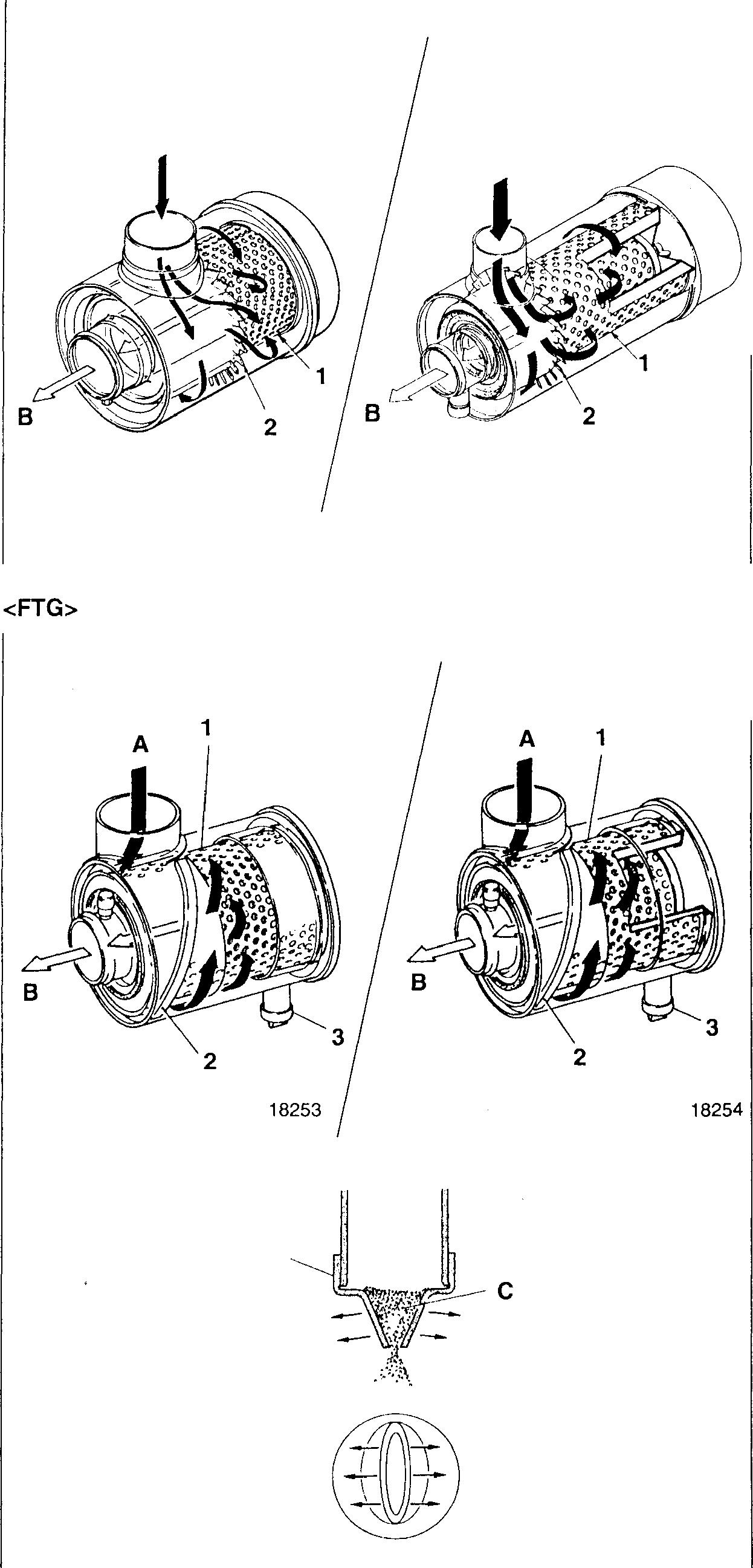
1 Element
2 Vane
A: Outside air
B:To engine
The element 1, which comes in two types; the single and double element types, is the filter paper type. Coated with plastics and given heat treatment, the elementoffersoutstanding resistance to water and oils.
Theairthathasbeendrawninismadetorotate by the vane 2, and large particles of dust are centrifugally separated. Furthermore, small particlesof dust arefiltered out by the filter paper element, and the air thus made clean is drawn into the engine.
1 Element
2 Guide vane
3 Vacuator valve
A: Outside air
B:To engine
The element 1, which comes in two types; the single and double element types, is the filter paper type. Coated with plastics and given heat treatment, theelement offers outstanding resistance to water and oils.
Theairthathasbeendrawninismadetorotate bytheguidevane2, andlargeparticlesof dust are centrifugally separated. Furthermore, small particles of dust are filteredout by the filterpaperelement, andtheair thusmadeclean is drawn into the engine.
Thevacuatorvalve3automaticallydischarges the separated dust and dirt. When the engine speed lowers to a certain speed, the elasticity of the rubber valve overcomes the negative pressureintheaircleaner, thusopensanddischarges the dust and dirt C.
<Single element type> A 18251
A
<Single element type> 3 <Double element type>
<Double element type> 18268 18252
15
15-3
STRUCTURE AND OPERATION
Cartridge type air cleaner A
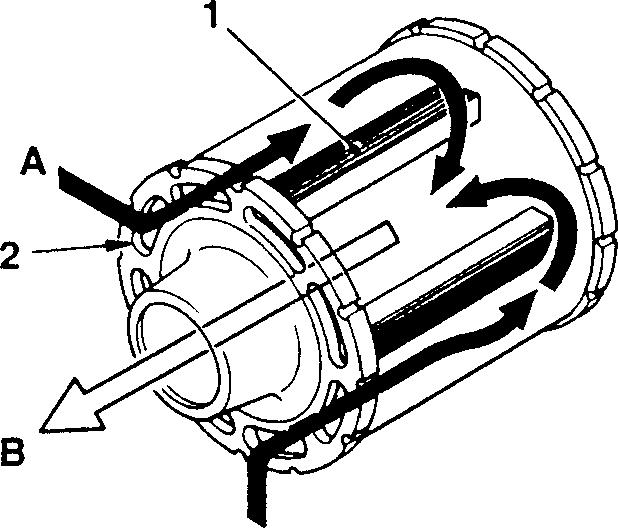
Pre-cleaner
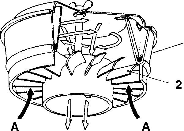
1
1 Element
2 Inlet slot
A: Outside air
B: Into engine
The element 1 is the filter paper type. The outside air is directly drawn in from the inlet slot 2 of the air cleaner proper.
1 Pre-cleaner body
2 Guide vane
A: Outside air
B:To air cleaner
The pre-cleaner removes relatively large particles of dust contained in the air that has been drawn in.
The air that has been drawn in is made to rotate by the guide vane 2 in the pre-cleaner, and the centrifugally separated particles of dust are accumulated in the pre-cleaner body 1.
15-4
B
18266
18267
Dust Indicator
<Mechanical
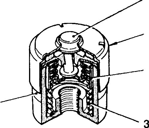
1 Dustindicator
2 Signal
3 Spring
4 Transparentportion
5 Reset button
A: Negativepressure
Themechanicaltypedustindicator1 islocatednearthe intake air outletof the air cleaner.
Operatedbythenegativepressurewhichisproducedwhenthe air is drawn into the engine, the dust indicator indicates that it is hightimeto cleanor replacethe element.
Inotherwords,whentheelementisdoggedwithdust, thesuctionresistanceincreases.WhenthenegativepressureAreaches 6.23 kPa {635 mmH20}, the signal 2 (red) is pulled down against the spring pressure of the spring 3. Sothe signal (red) appears inthetransparent portion 4 ofthebodytoindicatethat itis hightimetocleanor replace the element.
After cleaning orreplacing the element, pressthe reset button 5, andthe signal will return to its original position.
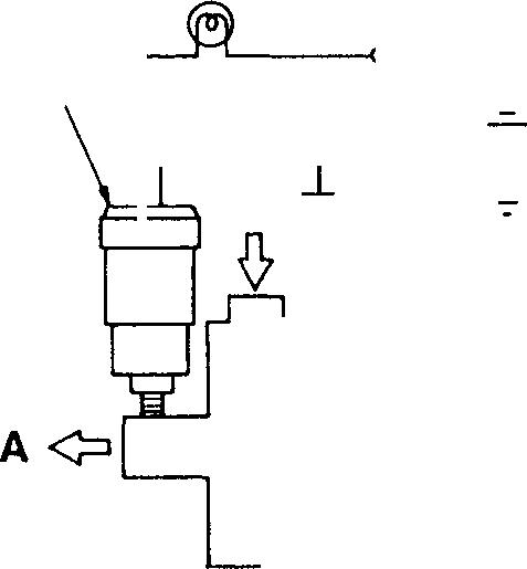
1 Dustindicator
2 Warning lamp
3 Starterswitch
4 Battery
5 Air cleaner
A: Negative pressure
WhenthenegativepressureAreaches6.23kPa{635mmH20}, the electric type dust indicator closes its contact to light the warning lamp 2 and alert the driver that itis high time to clean orreplacethe element.
type> 1 • A 2 5 1 2 3 � l 4 -=5 18269 18270
type> 4 <Electric
15
15-5
STRUCTURE AND OPERATION
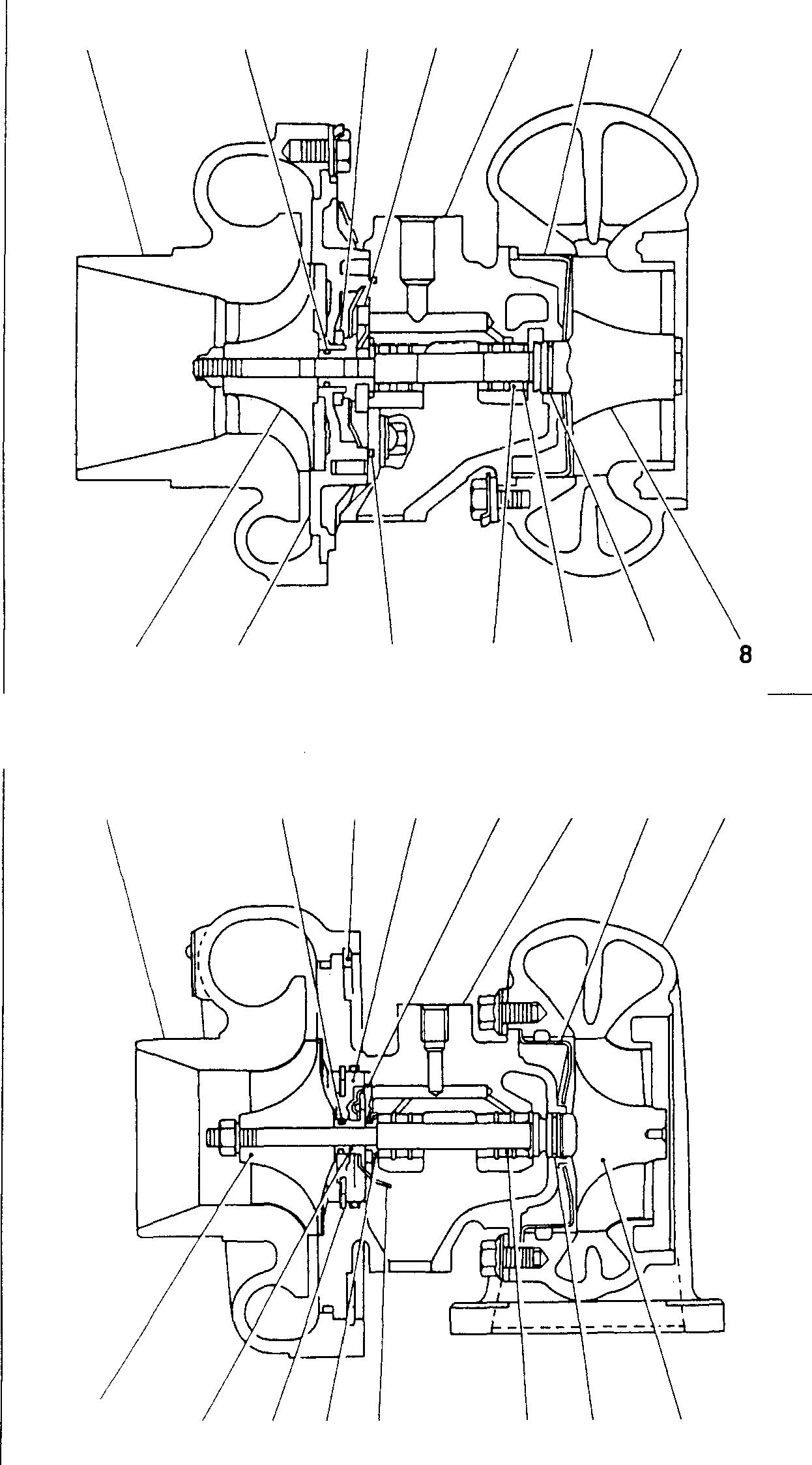
1 Compressor housing
1 Compressor cover
Piston ring
Snap ring
1 I5-6 / 16 1 2 14 13 2 3 12 3 15 14 1312 4 11 4 5 6 10 5 6 11 10 7 9 7 9 18271 8 18272
2 Piston
3 Thrust
4 Thrust bearing 5 Center housing 6 Wheel shroud 7 Turbine housing 8 Turbine wheel 9 Piston ring 10 Retaining ring 11 Bearing 12 Seal ring 13 Back plate 14 Compressor wheel
ring
collar
2
3
4 Insert 5
6 Bearing housing 7 Turbine back plate 8 Turbine housing 9 Shaft & turbine wheel assembly 10 Piston ring 11 Bearing 12 Oil deflector 13 Thrust ring 14 Snap ring 15 Thrust sleeve 16 Compressor wheel EARLY TYPE
Thrust bearing
LATE TYPE
LATE TYPE WITH ACTUATOR
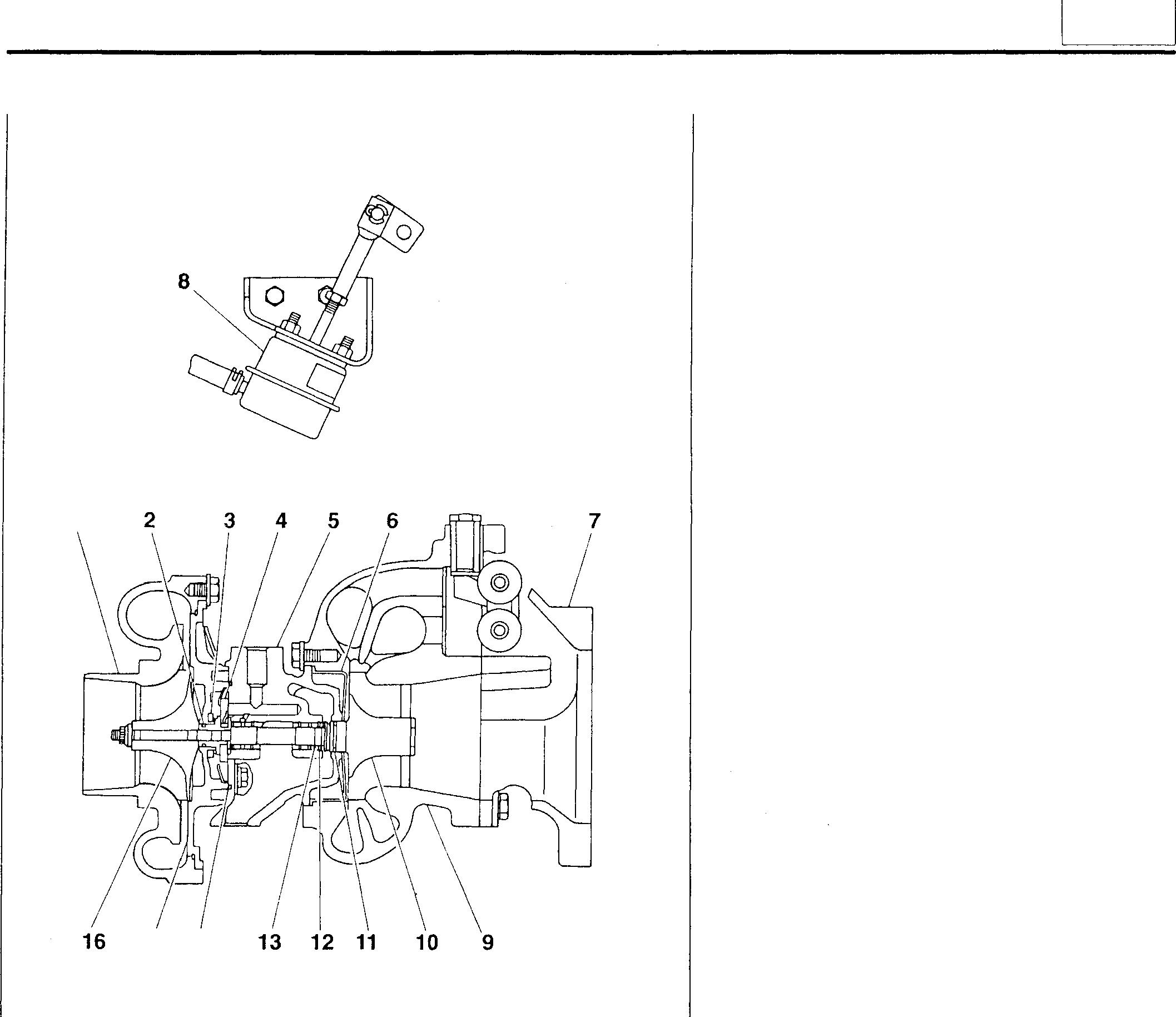
1 Compressorhousing
2 Piston ring
3 Thrust collar
4 Thrust bearing
5 Center housing
6 Wheel shroud
7 Exhaust coupler
a Actuator assembly
Turbine housing
1o Turbine wheel
Piston ring
Retaining ring
Bearing
Seal ring
Back plate
Compressor wheel
1 15 14 18273
g
11
12
13
14
15
16
15 15-7
STRUCTURE AND OPERATION
• Waste gatemechanism <6D16-TLEA>
• The waste gate mechanism has the actuator assembly 8 to let extra exhaustgasescape. Bysodoing, theboost pressure isproperlycontrolled to prevent the turbine wheel from overrunning and prevent an excessive pressure produced in the intake manifold.
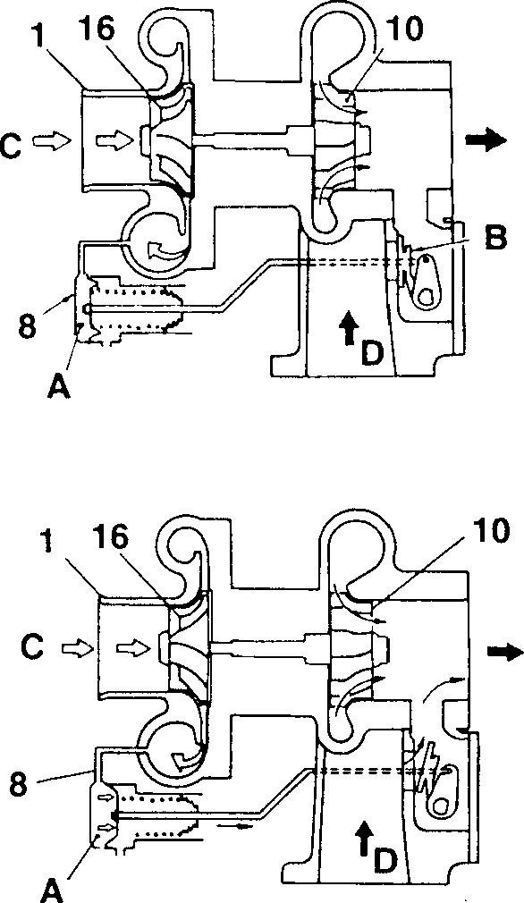
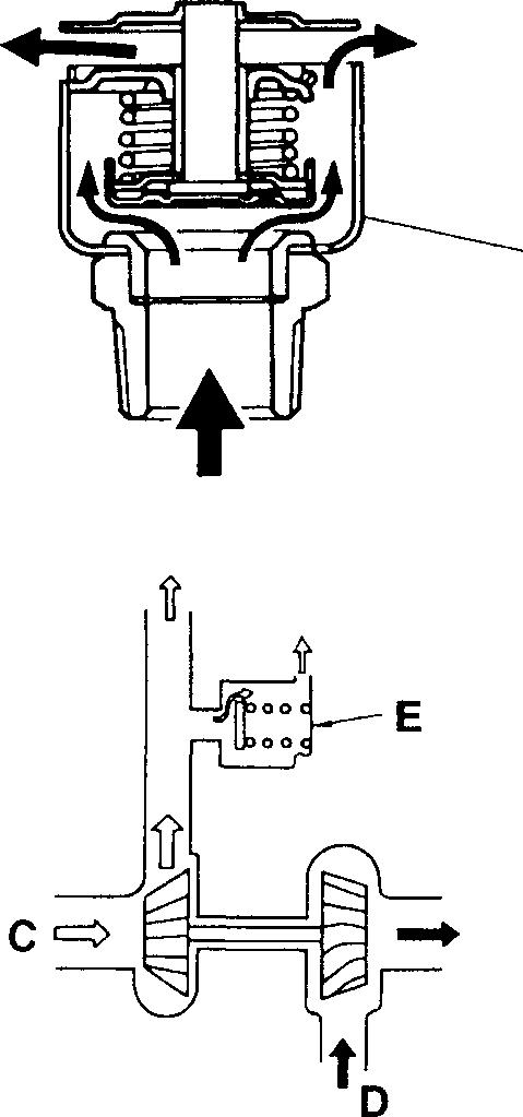
• The boost pressure is led from the compressor housing 1 through a rubber hose to the chamber A of the actuator assembly 8. When the boostpressurethatactsonthechamber A isbelowthesetting,theactuatorassembly does not operate, and the waste gatevalve remains closed, and the exhaust gas D isblown against the turbine wheel10.
• WhentheboostpressurethatactsonthechamberAexceedsthesetting,thewastegatevalveisopened.Asaresult,theamountofexhaust gas blown against the turbine wheel 1O decreases, and the rotating speedofthecompressorwheel16alsodecreases, andtheboostpressure falls.
• Operation ofoverboostvalve
• TheoverboostvalveEoperateswhentheboostpressurebecomesabnormally highdue tothe failure of the waste gate mechanism.
• WhentheboostpressureoftheoverboostvalveEexceedsthesetting, the valve releases the boost pressure into the atmosphere to make sure that a boost pressure more than necessary is notapplied to the engine.
Thevalvewhistleswhen itis in operation.
01510
01511
E
01512
15-8
01513
TROUBLESHOOTING
15 Symptoms "O ct! QJ ct! .!: C C :5 0 0 Q. li � :5 E .0 Remarks t:: 0 ::, ·;; ct! en en QJ en in ct! ct! .!: C oE 0) 0) 0 0) (.) in in C "O QJ c_ "O ::, ::, QJ ·o ::, en co ct! ct! c 0 >, .c .c QJ en en .c X X QJ > QJ - QJ QJ QJ ·c3 "ui en en C ;:,,:_ 2 :i= en C ::, ·o, (.) ::, QJ ct! ct! ct! :.c en (.) .... .c C X -x Possible causes w in 3: C w (/) QJAir cleaner Clogged aircleanerelement 00 0 Turbocharger Defective bearing 0 0 0 Carbon deposited onturbinewheel 0 0 Turbinewheel interfering withwheel shroudand 0 0 0 turbine back plate Turbinewheel interfering withturbine housing 0 0 0 Bent turbinewheel 0 0 0 Damaged turbinewheel 0 0 0 Compressorwheel interferingwith compressor 0 0 0 housing Thrust sleeve, thrustcollar andthrustbearing 0 0 0 seizure Damaged compressorwheel 0 0 0 Oilleaksdue toworn pistonring andinsert 00 0 Improperly mounted pistonring 0 Unsmooth
ofinternal partsdue
0 0 clogged
Damaged oil seals due
0 0 Improperly mounted compressor housing 0 000 Improperlymountedturbinehousing 0 0 lntercooler Foreign substances deposited
core of 0 intercooler Deformedfront pipe, muffler, tailpipe 0 Improperlymounted front pipe, muffler, tail pipe 0 Incorrect valve clearance 0 [O Gr 11 Defective head gasket 0 [O Gr11 Worn valveand valve seat and deposited carbon 0 lJ] Gr 11 Sagging valve spring 0 Gr 11 Worn or damaged piston ring 0 0 [O Gr11 Worn or damaged piston ringgrooveof piston 0 0 DJ Gr 11 Malfunctioning cooling equipment 0 OJ Gr 14 Excessive engine oil 0 i]] Gr12 Seizure of major moving parts 0 [O Gr11 Uneven or excessive fuel injection 0 [O Gr13 15-9
sliding
to
lubrication oil pipeand eyeball
tocloggedoilreturn pipe
on front
ON-VEHICLE INSPECTION AND ADJUSTMENT
Inspectionof Dust Indicator
Service standards
Location Maintenance item Standard value Limit Remedy
- Negative pressure for operation ofdust indicator 6.23± 0.57 kPa {635 ±58 mmH20} A
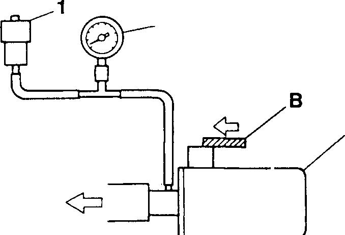
<MechanicalType>
�1
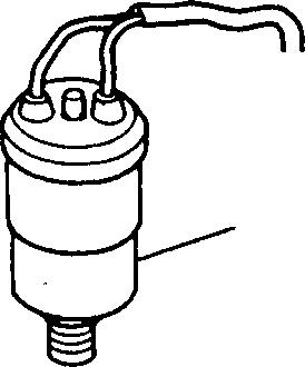
2 18274 <ElectricType> 1
• Before checking the dustindicator 1, clean or replace the air cleaner element.
• Startthe engine, and cover the inlet of theaircleaner through use of awoodenblockBinsuchawaythatthenegativepressureofthedust indicator1willhavethenominalvalueandcheckthatthemechanical type will showthe red signal or theelectric type will light the warning lamp. Ifthere isanything wrong inoperation, replace defectiveparts.
2 Aircleaner
A:Negativepressuregauge
15-10
18275
15
15-11
MEMO
AIR CLEANER <FHG, FWG>
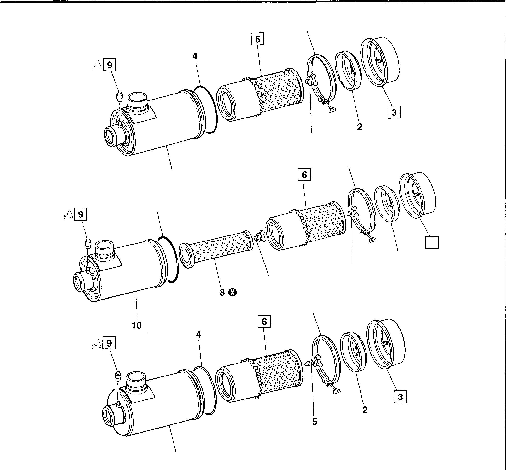
<FHG Single ElementType>
<FHG Double ElementType>
<FWG>
• Disassembly sequence
Clamp
Baffle
Dustcup
O-ring
Do not disassemble the safety element 8 except when it need be replaced.
• Reassembly sequence
Reverse the order of disassembly.
1
2
3
4
Nutgasket
Bolt
<FWG> Element
10 4 10 7 1 5 1 3 2 5 1 7 Nut gasket <FHGdoubleelement type> 8 Safety element <FHGdouble elementtype> 9 Dustindicator 10 Air cleaner body 0: Non-reusable part
<FHG>
gasket
NOTE
I5-12 18276 18277 18278
Service standards
Location Maintenanceitem Standard value Limit Remedy
9 Negativepressureforoperationof dustindicator 6.23±0.57 kPa(635±58mmH20} - Replace
� Sealant
Location Points of application Kinds Quantity
9 Apply to threadsof dustindicator
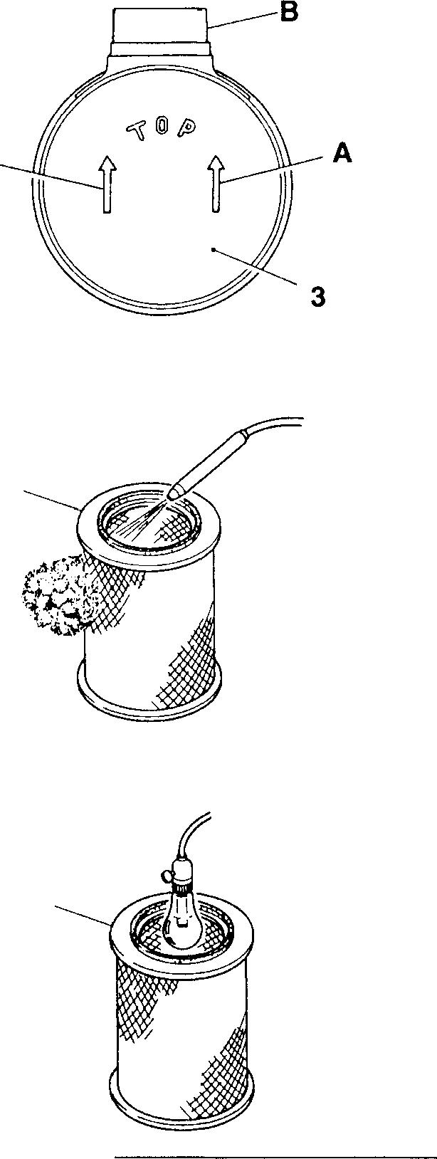
♦
Service
THREEBOND1401B
[fil Dust cup Asrequired
procedure
Reassemblethedust cup 3 with thearrow mark A toward theinlet B.
[]] Element
[Cleaning]
• Blow compressed air 685 kPa {7 kg/cm2} or less from inside the element 6.
• Blow thecompressedair, working along the creases of filter paper of the element 6 up and down throughout theelement.
CAUTION&_--------------
• Do not strike the element 6 to loosen dust.
• Do not blow the air from outside the element 6.
[Inspection]
• Put a light insidetheelement 6.
• Ifthefilterpaperisbrokenorpartially thin, orifthepackingonthetop of theelement 6 is broken, replace theelement.
• Ifthedustdepositedontheelement6iswetwithoilsmokeorsoot, replace theelement irrespective ofthe replacement intervals.
15
A 18279 6 13996
13997
6
15-13
AIR CLEANER <FHG, FWG>
[fil Inspection of dust indicator
Perform thefollowing checks. Ifthereisanything wrong, replace the dust indicator.
<Mechanical type>
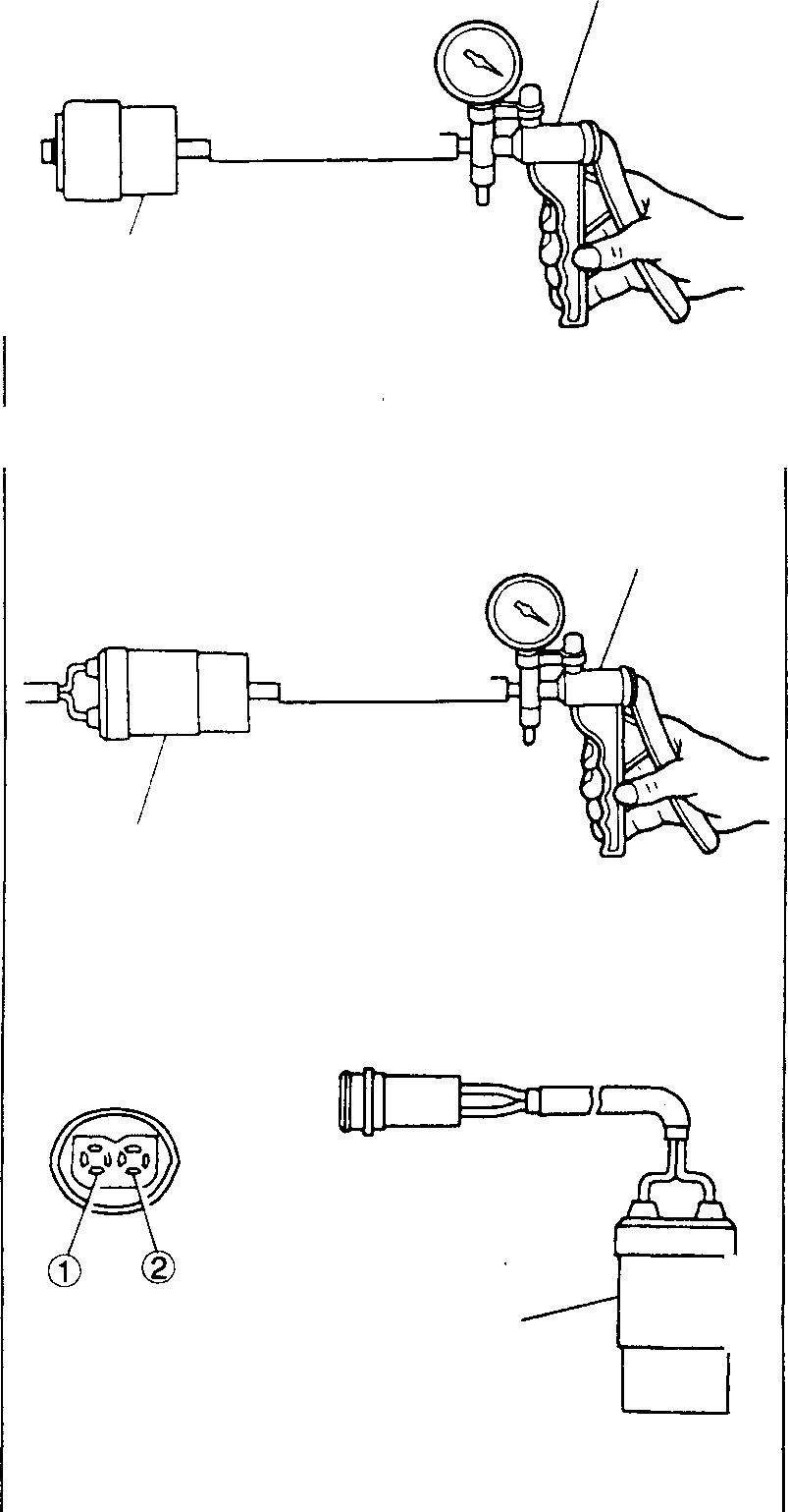
I• Mount a hand vacuum pump A on the dust indicator 9 and apply the standard operating negative pressure to check whether the red signal appears.
<Electric type>
• Mount a hand vacuum pump A on the dust indicator 9 and apply the standard operating negative pressure to check that there is continuity between terminals G) and®.
• Checkthatwhenthereisnonegativepressureappliedtothedustindicator 9, there is no continuity between the terminals G) and®.
A
9 A 9 9 15-14
18281
18282
18280
1s I MEMO 15-15
AIR CLEANER <FTG>
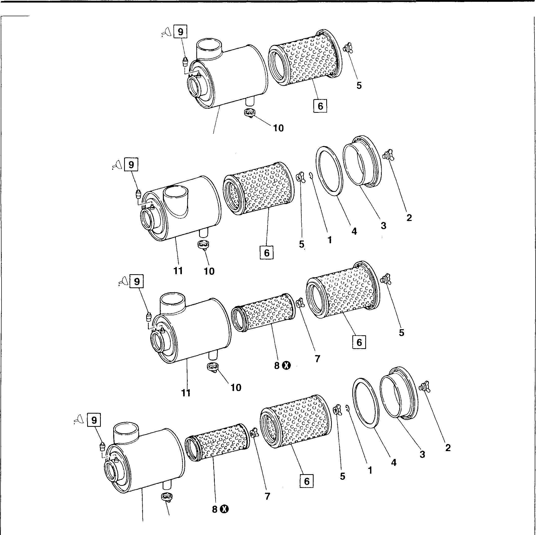
<Single Element Type>
<Type A>
<Type B>
<Double Element Type>
<Type A>
<Type B>
• Disassembly sequence
1 Clip <Type B>
2 Wing nut <Type B>
3 Cover <Type B>
Gasket <Type B>
Nut gasket
Element
Do not disassemble the safety element 8 except when it need be replaced.
• Reassembly sequence
Reverse the order of disassembly.
5
6
11 10 7
NOTE 11 8 Safetyelement <Doubleelement type> 9 Dust indicator 10 Vacuator valve 11 Air cleaner body 0: Non-reusable part
4
Nut gasket <Double element type>
15-16 18283 18284 18285 18286
Servicestandards
Location Maintenance item Standard value Limit Remedy
9 Negative pressure for operationof dust indicator 6.23 ±0.57 kPa {635± 58 mmH20} - Replace
� Sealant
Location Points of application Kinds Quantity
9 Applyto threadsof dust indicator
THREEBOND 14018
♦ Service procedure � Element
[Cleaning] As required

• Blow compressed air 685 kPa {7 kg/cm2} or less from inside the element 6.
• Blow the compressed air, working along the creases of filter paper of the element 6 up and down throughout the element.
CAUTION&--------------
• Do not strike the element 6 to loosen dust.
• Do not blow the air from outside the element 6.
(Inspection]
• Put a light inside the element 6.
• If the filter paper is broken or partially thin, or if the packing on the top of the element 6 is broken, replace the element.
• If the dust deposited ontheelement 6 is wet with oil smokeor soot, replace the element irrespective of the replacement intervals.
[]] Inspection of dust indicator
Performthefollowingchecks. If thereis anything wrong, replace the dust indicator.
<Mechanical type>
• Mount a hand vacuum pump A on the dust indicator 9 and apply the standard operating negative pressure to check whether the red signal appears.
15
13996
13997 A 9 18281
6
6
15-17
AIR CLEANER <FTG>
<Electric type>
• Mount a hand vacuum pump A on the dust indicator 9 and apply the standard operating negative pressure to check that there is continuity between terminals G) and®.
• Checkthatwhen there isno negative pressure applied tothe dust indicator 9, there is no continuity between the terminals G) and®.
A 9
9
15-18
18282
18280
AIR CLEANER <CARTRIDGE> 15
• Disassembly sequence
1 Clamp
2 Air cleaner
3 Dust indicator
• Reassembly sequence
Reverse the order ofremoval.
0----1
18287
Service standards
Location
Maintenanceitem Standardvalue Limit Remedy
3 Negativepressureforoperation ofdustindicator 6.23±0.57 kPa (635±58 mmH20} - Replace
� Sealant
Location
3
3 Points ofapplication Kinds Quantity Applyto threadsofdustindicator
THREE BOND 14018
♦ Service procedure
[fil Cleaning air cleaner
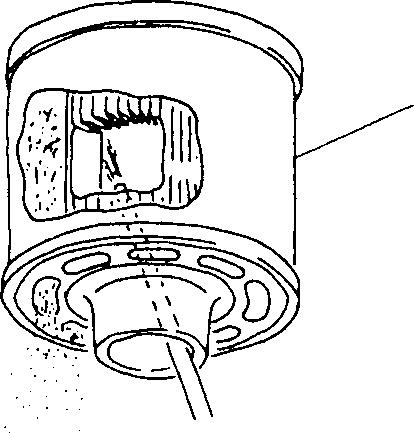
2
As required
18288
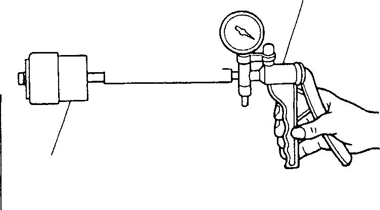
[Cleaning]
Blowcompressedair685kPa{7kg/cm2}orlessfrominsidetheaircleaner 2, workingalong the creasesof filterpaper up anddown to clean the air cleaner.
CAUTION&_--------------
• Donotstriketheelement and donot blowthe air from the suction portion.
• Make sure that the loosened dust is not blown into the element.
[1J Inspection of dust indicator
• MountahandvacuumpumpAonthedustindicatorandapplythestandardoperatingnegativepressure to check whether theredsignalappears.
A 18281
15-19 Pages
to 15-29 are deleted as they are not in use.
15-20
TURBOCHARGER 6D16-TLEA
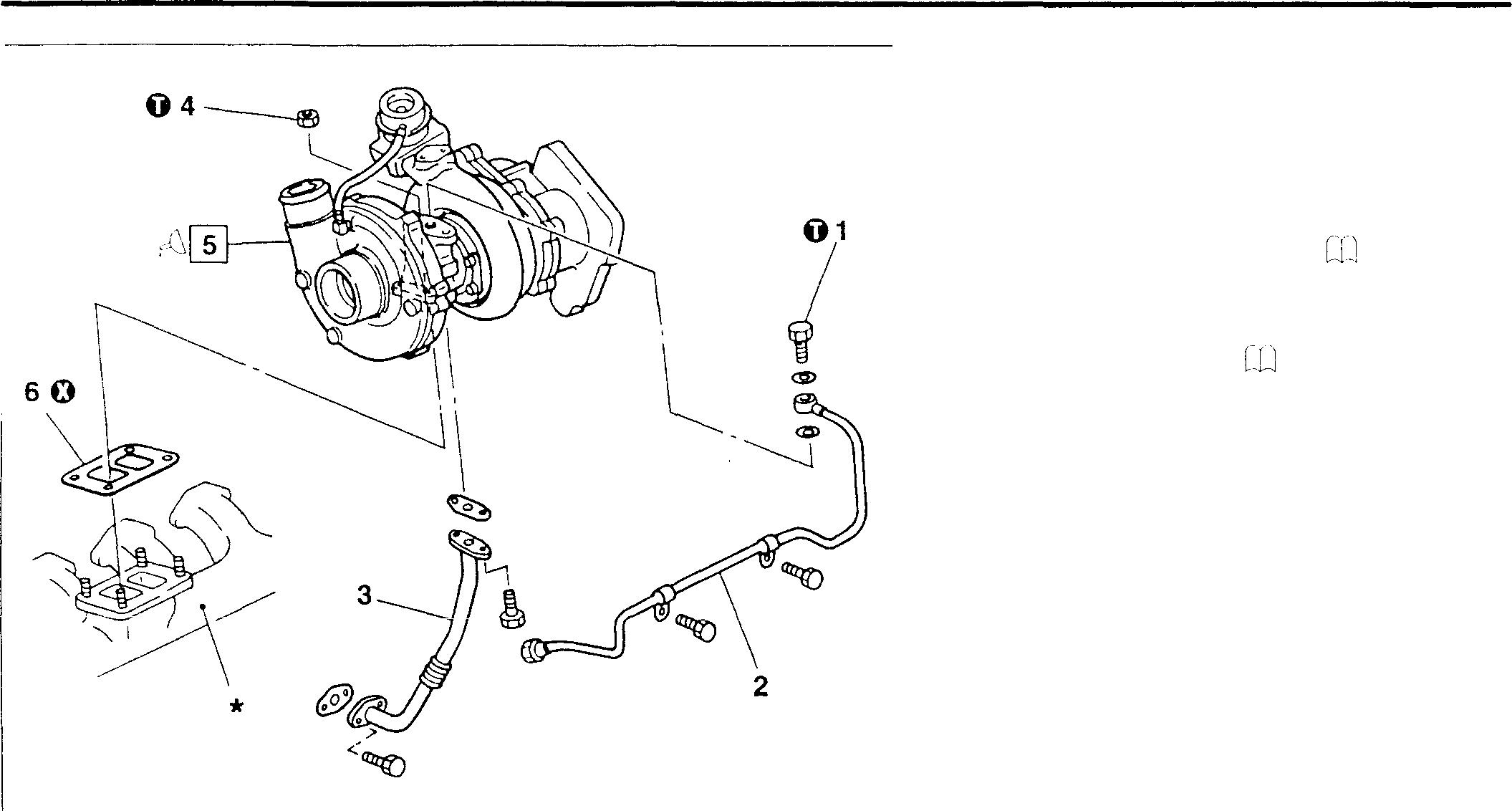
18387
O Tightening torque
Location Parts to be tightened
1 Eyebolt (for mounting oilinletpipe)
4 Nut (for mounting turbocharger assembly)
Lubricant Location Points of application
5 Supplywhen installing turbochargerassembly
• Removal sequence
1 Eyebolt
2 Oil inlet pipe
3 Oil return pipe
4 Nut
5 Turbocharger assembly
6 Gasket P.15-32
*: Exhaust manifold P.15-60, 61
0: Non-reusable part
• Installation sequence Reverse the order of removal. Unit:
♦ Service procedure
5
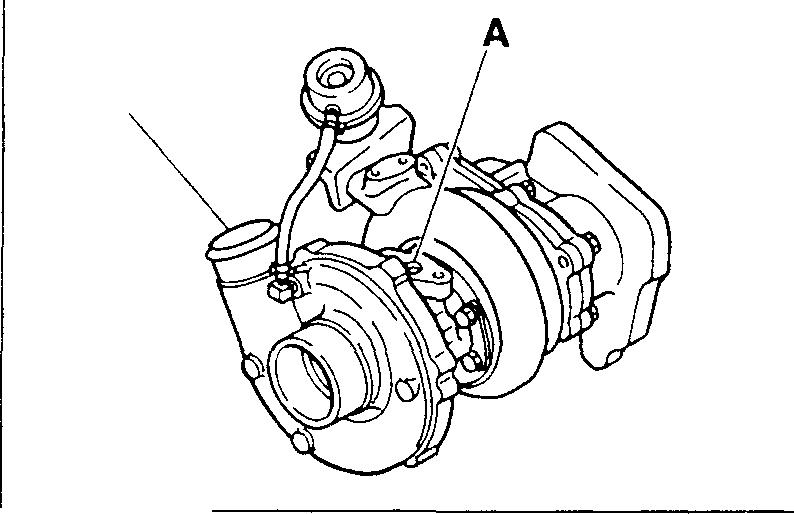
[fil Installation of turbocharger assembly
Whentheturbochargerassembly5isinstalled,supplyengineoilfromthe oil hole A to make sure that all the partsoperate smoothly.
18388
N·m {kgf·m} Tightening torque Remarks 21
-
41
�
Kinds Quantity
{2.1)
{4.2)
Engine
As required
oil
15-30
I 1s I MEMO 15-31
TURBOCHARGE 6D16-TLEA
Turbocharger Assembly
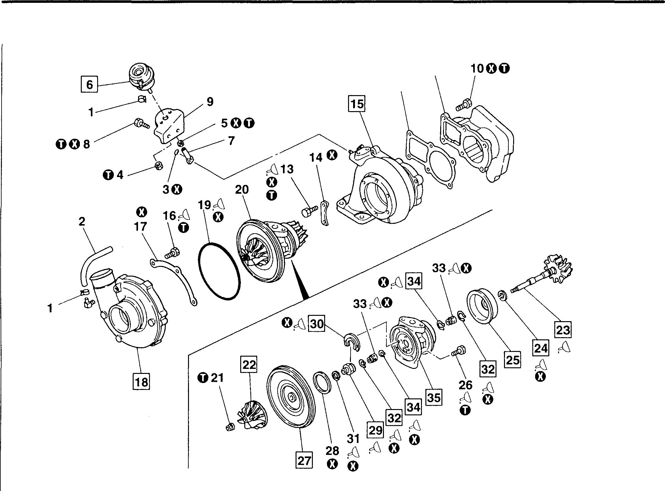
CAUTION&-------------------------
Carefully remove the piston rings 24 and 31, as they are readily broken.
• Operations
0: P.15-34 • Disassembly sequence 1 Hoseclamp 2 Hose 3 Retainingring 4 Nut 5 Nut 6 Actuator assembly 7 Rod end 8 Bolt 9 Bracket 10 Bolt 11 Exhaustcoupler 12 Gasket 13 Bolt 14 Clamp 15 Turbinehousing 16 Bolt 17 Clamp 18 Compressorhousing 19 O-ring 0 11 12 20 Centerhousing & rotating assembly 21 Locknut 22 Compressorwheel 23 Turbinewheel 24 Piston ring 25 Wheelshroud 26 Bolt 27 Backplate 28 Sealring 29 Thrustcollar 30 Thrustbearing 31 Piston ring 32 Retaining ring 33 Bearing 34 Retaining ring 35 Centerhousing O:Non-reusablepart 18315
before disassembly
15-32
• Cleaning after disassembly Cl] P.15-35
• Reassembly sequence
CAUTION&------------------------Do not widen the piston rings 24 and 31 more than necessary, as they are readily broken.
• Inspection after reassembly CO P.15-35
standards
Mitsubishi 6D16TLEA engine parts contact: email: engineparts2@gmail.com Phone: 269 673 1638
269 760 8652
35➔34➔33➔32➔29➔30➔31➔28➔27➔26 y 22➔21➔20➔19➔18➔17➔16 7 24➔23 L 15➔14➔13➔12➔11➔10➔9➔a➔6➔4➔5➔7➔3➔2➔1 15
Service
Location Maintenance item 6 Actuatorassemblysetpressure 23 Turbine Bearing journal outside diameter wheel Shaftbend Hubdiameter Piston ring mounting Groove portion width Groove diameter Playinradialdirection Playinthrustdirection 27 Backplate Seal land height Seal bore insidediameter 29 Thrust Piston ring mounting Groove collar portion width Groove diameter Thrustbearingmounting Groove portion width Groove diameter Insidediameter 35 Center Bearinginserting portion inside housing diameter Seal bore insidediameter Standard value Limit (Basic diameter in [ ]) 83to 90kPa {625to 675mmHg}[10.156] 10.152or more - 0.01or less [17.31] 17.25or more 1.69 1.74or less [14.46] 14.40or more 0.076to 0.1500.025to 0.07611.672 11.658or less [12.687] 12.712or less 1.640 1.659or less [10.35] 10.29or more 4.43 4.44or less [9.53] 9.40or more [6.358] 6.363orless [15.800) 15.806or less [18.03) 18.06or less Unit: mm Remedy Adjust Replace Check Replace Replace Replace 15-33
Text:
TURBOCHARGER 6D16-TLEA
0
Nut (formounting actuator assembly)
Nut (for mounting rodend)
0.80}
0.70}
to2.3(0.21to 0.23) After tightening, turndown90°C to 110°C further from that position. 26 Bolt (formountingback plate)
to14 {1.26to 1.45} -
/:i Lubricants
of application
Applytothreadsand bearingsurfaceofbolt
Apply to threadedportion of bolt
� Special tools
Part No. Application
801059-0
Removaland installation ofcompressor
801053-0 wheel
801098-0
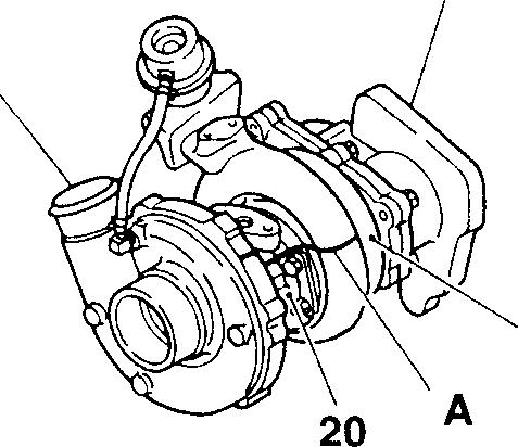
Inspectionofplay of turbine wheel in radial direction
801050-0 Installation ofpiston ring
801058-0 Removal and installation of retaining ring
♦ Service procedure
• Operations before disassembly Make alignment mark A on the turbine housing 15, compressor housing 18 and center housing & rotating assembly 20.
Tightening torque Unit: N·m {kgf·m} Location Parts to be tightened Tightening torque Remarks 4
5.6
5
5.6
8 Bolt (for mounting bracket) 20
22
10 Bolt (for mounting exhaust
20to22
13 Bolt (for mounting clamp) 20to22 {2.07 to
16 Bolt (for mounting clamp) 16to 19 {1.67
21
2.1
12
to 7.8 (0.57to
to 6.8 (0.57to
-
to
{2.07to2.29}
coupler)
{2.07to2.29}
2.29}
to 1.89)
Lock nut (for mountingcompressor wheel)
Location Points
Kinds Quantity 13
MOLYKOTE Asrequired 16,26
19, 23,
all
24, 29 to 34
Applyto
of the parts.
Location Tool name and shape T-handle 22 Holding fixture 23 Measuringelement 24 Pistonring inserter 32,34 Retainingring remover 11 18 15 18316 15-34 LOCTITE As required Engineoil As required
Mitsubishi 6D16TLEA engine parts contact: email: engineparts2@gmail.com Phone: 269 673 1638 Text: 269 760 8652
• Cleaning after disassembly
• Before cleaning, visually check the individual parts for burns, rubbed stains, etc. which might disappear after cleaning. If there is anything wrong, replace.
CAUTIONLt,--------------
Do not immerse the actuator assembly 6 in the solvent. Clean it with a cloth dipped in kerosene.
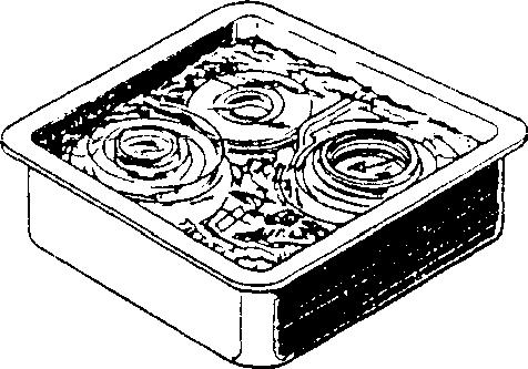
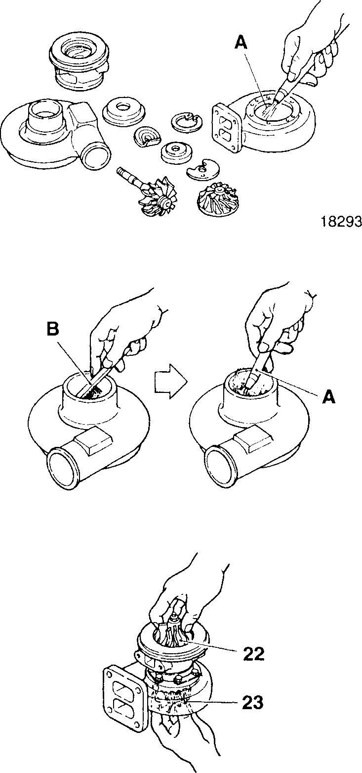
• Immersethedisassembledpartsinanon-combustiblesolvent(0AIDO CHEMICAL INDUSTRY CO., LTD.DAI CLEANER T-30).
• TakeoutthepartsfromthesolventandblowcompressedairAagainst them.
• Scrape off deposits.
B: Plasticscraper orstiff brush
• Re-immerse in the solvent.
• Blowcompressed air A.
• Inspection after reassembly
(1) Manually rotate the compressor wheel 22 and turbine wheel 23 to check whether they rotate smoothly.
13630 18358
13628
15-35
TURBOCHARGER 6D16-TLEA
(2) Play of turbine wheel in radial direction
• Mount the (&] Measuring Element to the dial gauge A and insert it from the oil outlet and press it against the shaft of theturbine wheel 23 at right angles.
• Move the shaft of the turbine wheel 23 up and down by both hands to measure the play in the radial direction.
• If the reading exceeds the limit, replace the bearing 33.
(3) Play of turbine wheel in thrust direction
• Set the dial gauge A on the end of the turbine wheel 23 and move the shaft of the turbine wheel in the axial direction to measure the play.
• If the reading exceeds the limit, worn or defective back plate 27, thrust collar 29 and thrust bearing 30 are suspected. Replace.
(4) Measurement of operating pressure of actuator assembly
• Set the dial indicator A on the end of the rod end 7. (In this case, set the scale of the dial indicator to 0.)
• Extend the rod end 0.38 mm by use of the external air B.) (The scale of the dial indicator A is 0.38 mm.)
• With the scale of the dial indicator A at 0.38 mm, read the value of the pressure gauge C, and check to ensure that the reading is between 83 and 90 kPa {625 to 675 mmHg}.
(5) Adjustment of operating pressure of actuator assembly
• IfthereadingofthepressuregaugeC isnot between 83and90kPa {625 to 675 mmHg}, remove the retaining ring 3, loosen the nut 5, and adjust the length of the rod end 7.
Rod end length adjusting direction
Rod end extending direction � Reduces the pressure. Rod end retracting direction -> Increases the pressure.
CAUTION&------------
When the rod end length is adjusted, if the piston assembly D is rotated, damage to the diaphragm in the actuator assembly 6 will result. Secure the piston assembly through use of avice, pliers, etc. to make sure that it is not rotated.
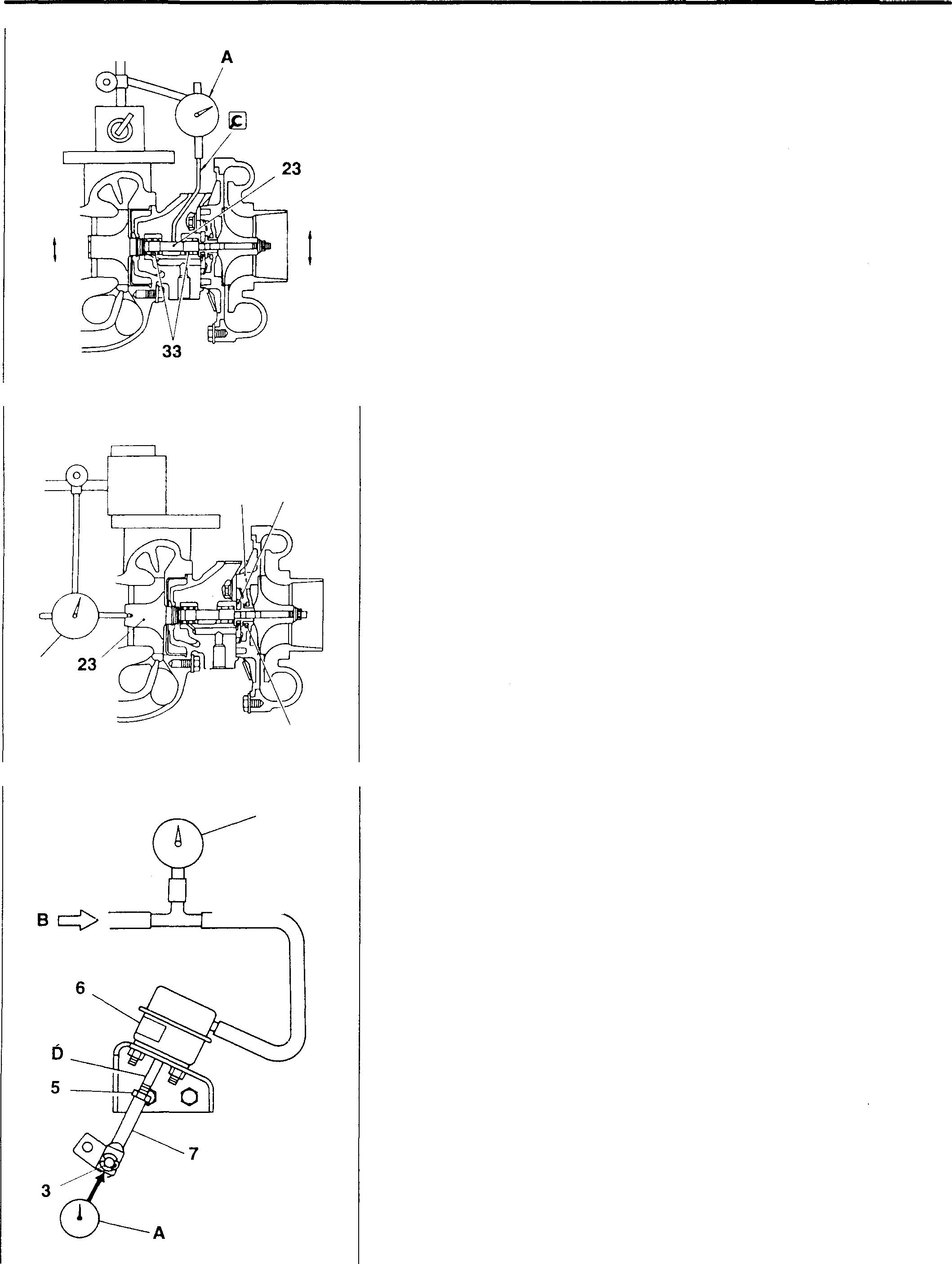
i8317 27 30 A 29 18318 C 18325 15-36
[fil Air-tightness check on actuator assembly
Slowlyapplytheairpressure A totheactuatorassembly 6 tocheckthat therearenoairleakswhentheairpressureis87kPa{650mmHg}.Ifthere are airleaks, replacetheactuatorassembly.
B: Pressuregauge
� Turbine housing
[Removal]
A: Rubberhammer
CAUTION&--------------
• While using care to prevent damage to the turbine housing 15, lightly strike its entire circumference with a rubber hammer or similar tool.
• Since theblades ofthe turbinewheel23are readilybent, usecare to make sure that they do not hit the turbine housing 15.
[Installation]
Apply MOLYKOTEtothethreadsandbearingsurfaceofbolt 13, partially tighten thebolt, line up thealignmentmarks made before disassembly, andthentightenthebolt to thespecifiedtorque.
CAUTION&-
Use care toprevent damage to the blades of the turbine wheel23.
� Compressor housing
[Removal]
A: Rubber hammer
CAUTION&--------------
• While usingcaretopreventdamagetothecompressor 18, lightly strike its entire circumference with a rubber hammer A or similar tool.
• Sincethebladesofthecompressorwheel22 arereadily bent, use caretomakesurethatthey donot hitthecompressorhousing 18.
[Installation]
• Place the center housing & rotating assembly 20 on the compressor housing18, lineupthealignmentmarksmadebeforedisassembly,and tighten the bolt 16 tothespecifiedtorque.
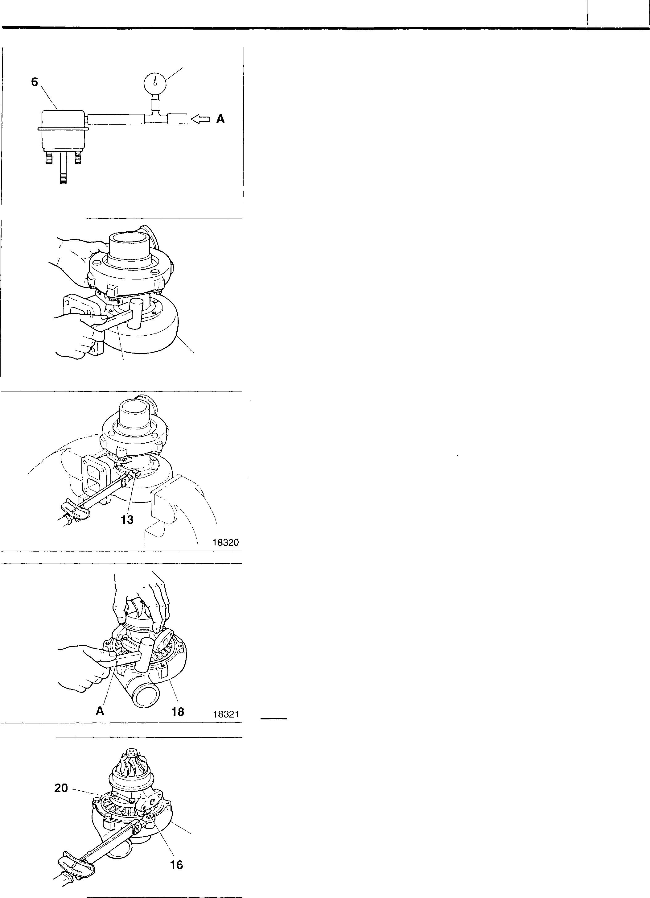
8 18366 A 15 18319 18 18322 15
15-37
TURBOCHARGER6D16-TLEA
� Compressor wheel
[Removal]
• Hold the �a Holding Fixture in a vice, and slowly insert the center housing & rotating assembly 20.
• Using the 1gb T-handle, remove the lock nut 21 and slowly withdraw the compressor wheel 22 upward.
CAUTION&-------------
Use care to prevent bending the shaft of the turbine wheel 23.
[Installation]
• Hold the shaft of the turbine wheel 23 and center housing 35 by hand, and slowly insert them into the �a Holding Fixture.
CAUTION&--------------
• Whenthey areinserted, use care to preventdamage to theblades of the turbine wheel 23.
• Do not release the shaft before insertion, as the turbine wheel 23 falls down.
• Holdthe �a Holding Fixturein avice andslowly insertthe compressor wheel 22.
• Using the �b T-handle, tighten the locknut 21 to the specified torque, and then turn it down 90°C to 110°C further from that position.
CAUTION&--------------
Use care to prevent bending the shaft of the turbine wheel 23.
� � Turbine wheel, wheel shroud
[Removal]
Placethebackplate27ofthecenterhousing35onthecompressorhousing 18 removed beforehand, and remove the turbine wheel 23 and wheel shroud 25.
[Installation]
After installation, lightly rotate the turbine wheel 23 by hand to check whether it continues to rotate. If it does not rotate lightly, re-perform the disassembly and reassembly procedures.
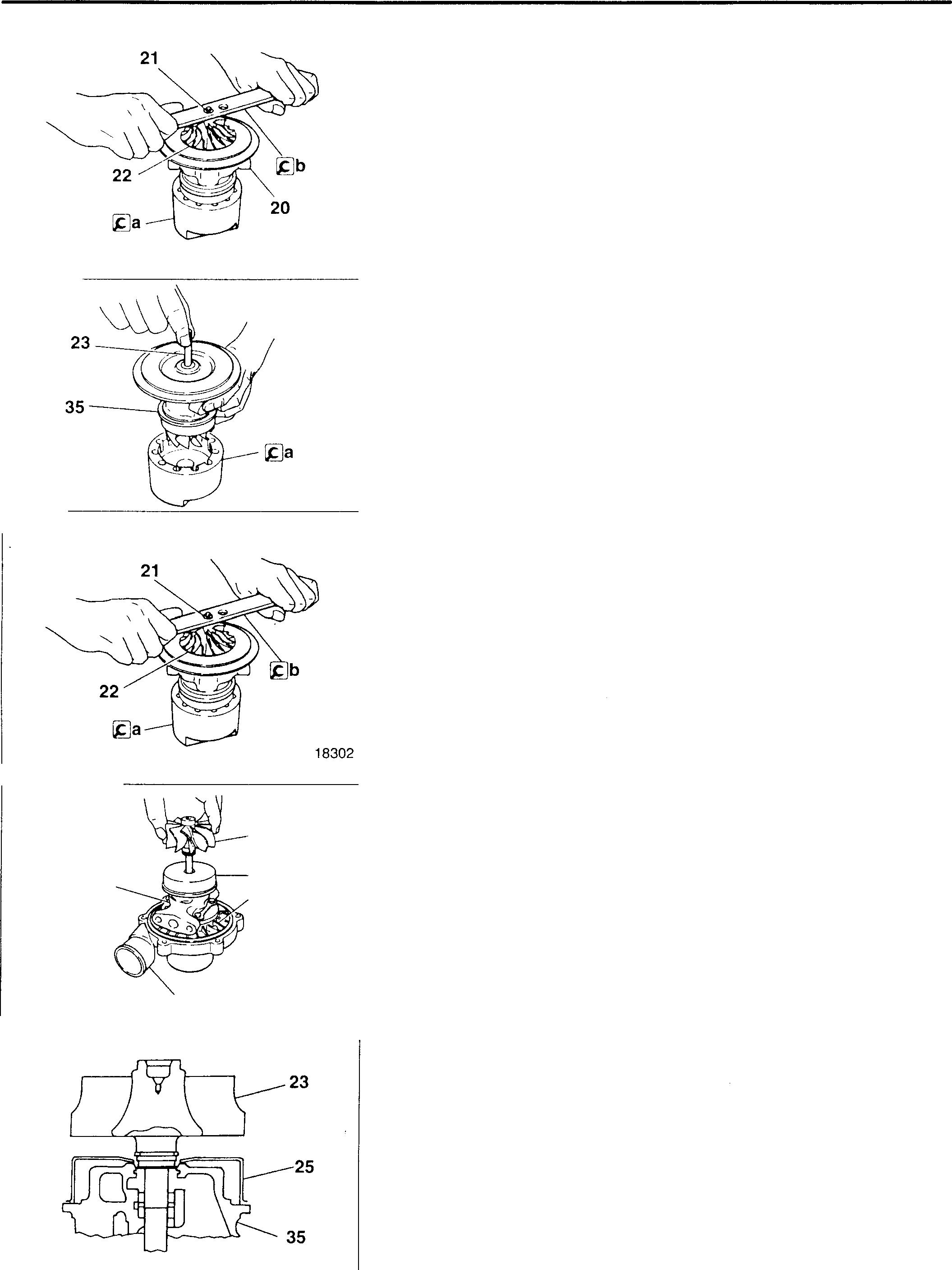
35 15-38 18 23 25 27 18300 18301 18303 18304
[Inspection]
(1) Bend of shaft
• Using the dial indicator, measure at the illustrated position.
• If the reading exceeds the limit, replace the turbine wheel 23.
(2) Outside diameters of journal and hub
If any reading exceeds the limit, replace the turbine wheel 23.
A: Journal
B:Hub
(3) Width and outside diameter of piston ring groove
If any reading exceeds the limit, replace the turbine wheel 23.
A:Width
B: Outside diameter
� Installation of piston ring
Insert the � Piston Ring Inserter into the turbinewheel 23and install the piston ring 24.
� Back plate
[Installation]
Slowly install the back plate 27 on the center housing 35, while lining up the alignment marks made before disassembly, andtighten the bolt 26 to the specified torque.
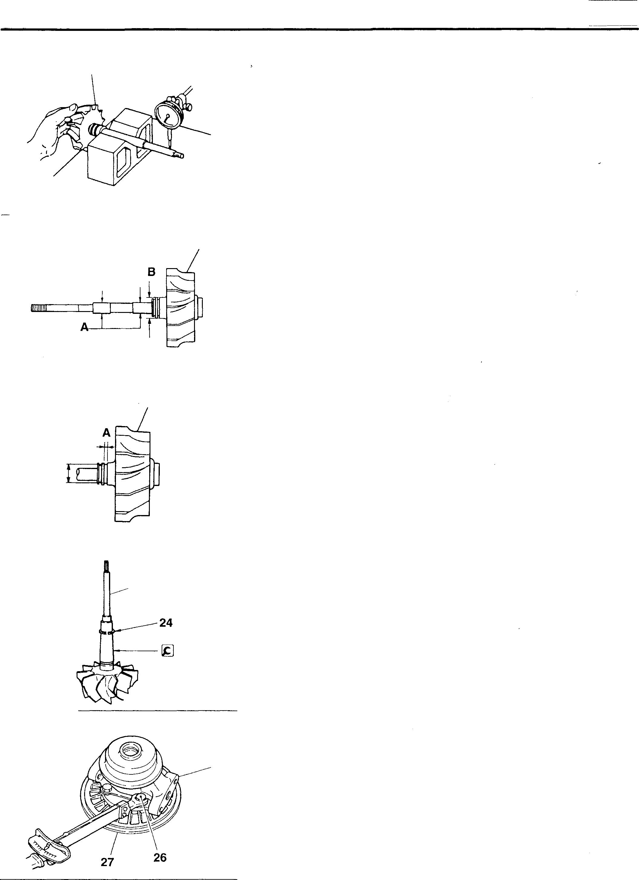
23 13655 23 18305 23 B 18306 ----23 18307 35 18308 L1s I
15-39
TURBOCHARGER 6D16-TLEA
[:=9§�,\
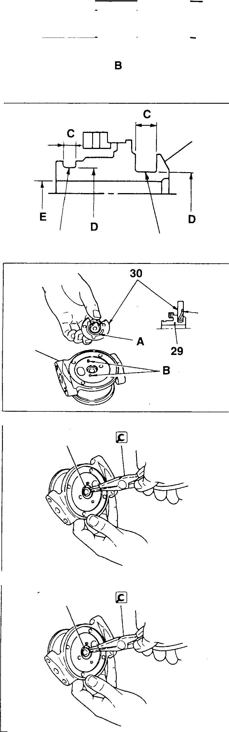
[Inspection]
• MeasuretheseallandheightAandsealboreinsidediameter 8 ofthe backplate 27.
• Ifany reading exceeds the limit, replace the back plate 27.
� Piston ring groove and groove diameter of thrust collar and thrustbearinggroovewidth, groovediameter and bore insidediameter
Ifany reading exceeds the limit, replace the thrust collar 29.
A: Piston ring groove
8:Thrust bearing groove
C:Groove width
D: Groove diameter
E: Bore inside diameter
@Q] Installation of thrust bearing
Installthe thrust bearing30 on the thrust collar 29 with the oil groove A toward thecenter housing 35, and insertitontothe positioning pins 8 of the center housing.
� � Retaining ring
[Removal]
�: Retaining Ring Remover
CAUTION&--------------
When the retaining rings32 and34 are removed, hold your hand over the rings to make sure that they do not bounce out.
[Installation]
Install the retaining rings32 and34 securely in the groove ofthe center housing.
CAUTION&--------------
When the retaining rings32 and34 are installed, hold your hand over the rings to make sure that they do not bounce out.
27
18309 29 A 8 18311 A 35 18312 32,34 18313 32,34 18313 15-40
� Check the bearing inserting portion inside diameter and seal bore diameter ofthecenter housing.
Ifanyreadingexceeds thelimit, replacethe center housing35.
A:Bearinginsertingportion insidediameter
B:Seal bore diameter
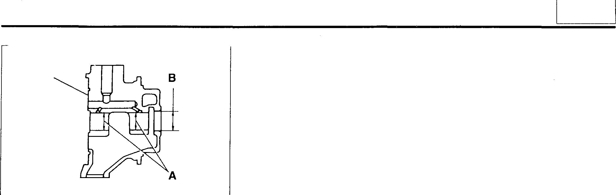
35 18314 15
15-41 Pages
are deleted as they are not in use.
15-42 to 15-51
INTERCOOLER 6D16-TLEA TOP HOSES
• Disassembly sequence
1 Clamp
2 Rubber hose
3 lntercooler
• Reassembly sequence
Reverse the order of disassembly.
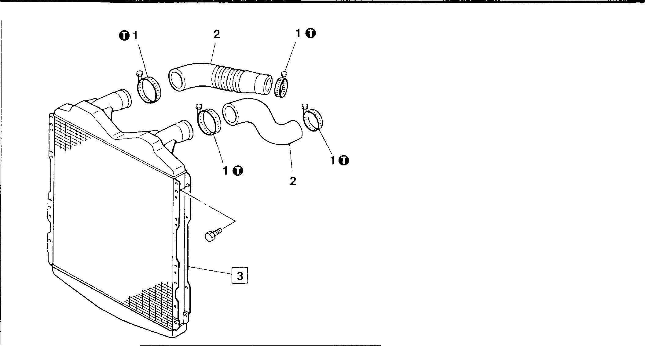
Service standards
Location Maintenance item
018348
Standard value
Limit Remedy
3 lntercooler (air leakatthe airpressureof 150kPa 0cm3 {0 ml} - Replace (1.5 kgf/cm2})
Tightening torque
Location Parts to be tightened
1 Clamp (for mounting rubber hose)
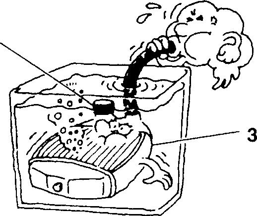
Tightening torque 4.9to9.8 (0.5to 1.0)
♦ Service procedure [1] Inspection of intercooler
Unit: N ·m {kgf·m}
Remarks -
Put a cap A on either of the air ports of the intercooler 3 and connect a hosetotheother, immerse the intercooler3 inawater tank, andapplythe standard pressure from the hose side to check for air leaks. If there are air leaks, replace the intercooler.
A
15-52
18349
INTERCOOLER 6D16TLEA SIDE HOSE TYPE
P Disassembly sequence
1 Clamp
2 Air inlet hose
3 Clamp
4 Air inlet pipe
5 Clamp
6 Air inlet hose
7 Boost air temperature sensor L Gr13E
8 Intercooler
P Assembly sequence
Follow the disassembly sequence in reverse.
Service standards
Location Maintenance item
Standard value
LimitRemedy
8 Air leakage from intercooler (Air pressure : 195 kPa {2.0 kgf/cm2}) 0 cm3 {0 mL}—Replace
T Tightening torque Unit : N·m {kgf·m}
LocationParts to be tightenedTightening torqueRemarks
1, 3, 5 Clamp (Air inlet hose and inlet duct mounting)4.9 to 9.8 {0.5 to 1.0}—
7 Boost air temperature sensor14.7±2 {1.5±0.2}—
Mitsubishi 6D16TLEA engine parts contact:
email: engineparts2@gmail.com
Phone: 269 673 1638
Text: 269 760 8652
15-24
5 1 T 1 T 7 T 3 T T 5 8 T 6 4 2 13458
I 1s I MEMO 15-53
♦ Service procedure
[I] Installation of air heater
Theairheater 4shouldbeinstalledwithitsarrowmark A directedtoward the intake manifold7.
[I] Installation of intake manifold
• Theintakemanifoldisinstalledbyuse ofeitheraseatgasketorsealant. This sectiondescribestheproceduresforinstallation byuse ofa sealant.
• Applysealant A evenlywithoutabreaktothecylinderheadmounting surface ofthe intake manifold7.
• Installthe intake manifold onthecylinderheadinlessthanthree minutesafterapplicationofsealant A.
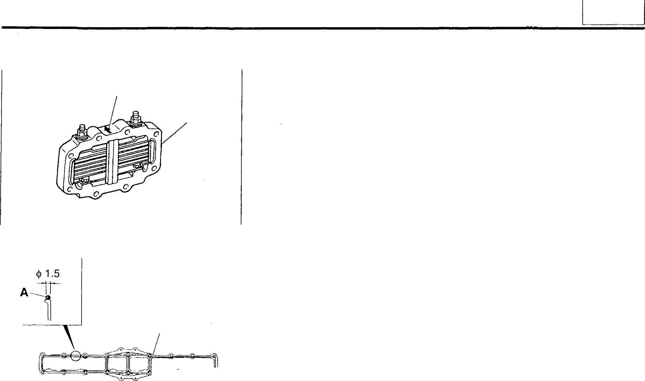
CAUTION&--------------
• Thoroughly clean the sealant applyingsurface of the intake manifold 7 beforehand.
• Whentheintakemanifold7isinstalled, makesurethatitisnot out of alignment.
• When the manifold mounting bolt 6 was loosened, be sure to reapply sealant A to the intake manifold 7.
• Do not start the engine in less than an hour after installation.
A 4 18698 7 ,=="�'==®� 18339
15
15-55
INTAKE MANIFOLD-NOINTERCOOLER TYPE
<Exhaust outletforward specification>
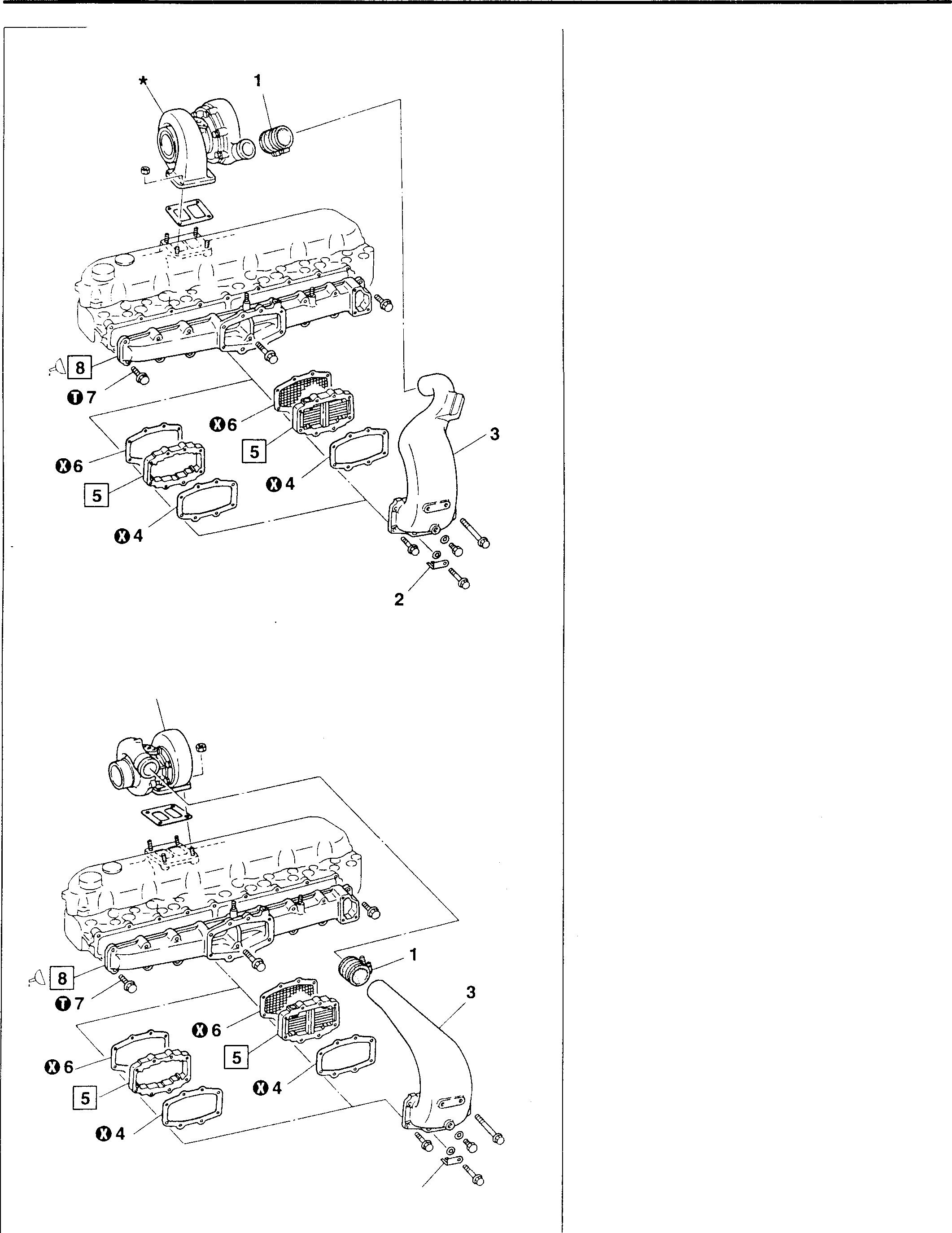
<Exhaust outletrearward specification> *
• Disassemblysequence
1 Rubber hose
2 Earth plate <with air heater>
3 Air inlet pipe
4 Gasket
5 Air heater <withair heater>
Spacer <withoutair heater>
6 Gasket
7 Bolt
8 Intake manifold
*:Turbocharger assembly [O P.15-20, 42
O: Non-reusable part
• Reassembly sequence
Reverse the order of disassembly.
15-56 18340 2 18341
0
Tightening torque
Location Parts to be tightened
Unit: N·m {kgf·m}
Tightening torque Remarks
7 Bolt(formounting intakemanifold) 19{1.9} -
� Sealant
Location Pointsofapplication Kinds Quantity
8 Applytocylinderhead mountingsurface oftheintake THREE BOND 1207B As required manifold <With air heater> A
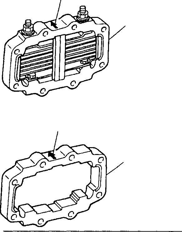
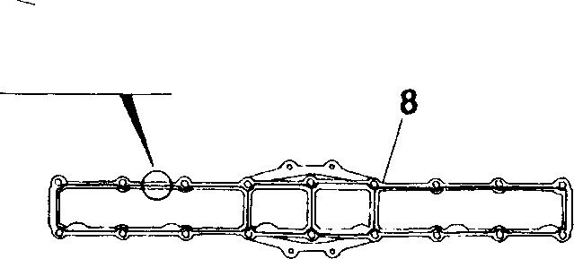
Al♦ Service procedure
[fil Installation ofair heaterorspacer
Theairheater 5 orthespacer 5 shouldbeinstalledwith itsarrowmark A directedtoward the intakemanifold8.
[fil Installation of intake manifold
• Theintakemanifold8isinstalledbyuseofeitheraseatgasketorsealant.Thissectiondescribesthe proceduresfor installationbyuseof a sealant.
• ApplysealantAevenlywithoutabreaktothe cylinder headmounting surface of the intake manifold 8.
• Installtheintakemanifold8onthecylinderheadinlessthanthreeminutes afterapplication ofsealant A.
CAUTION&-------------
• Thoroughlycleanthesealantapplyingsurfaceoftheintakemanifold 8 beforehand.
• Whentheintakemanifold8isinstalled,makesurethatitisnotout of alignment.
• Whenthemanifoldmounting bolt7wasloosened, besuretoreapplysealant Ato the intakemanifold8.
• Do not starttheenginein lessthan an hourafter installation.
15
5 <Without
heater> A 5 <jJ 1.5
air
18698 18699
18339
15-57
INTAKE MANIFOLD 6D16-TLEAINTERCOOLER TYPE
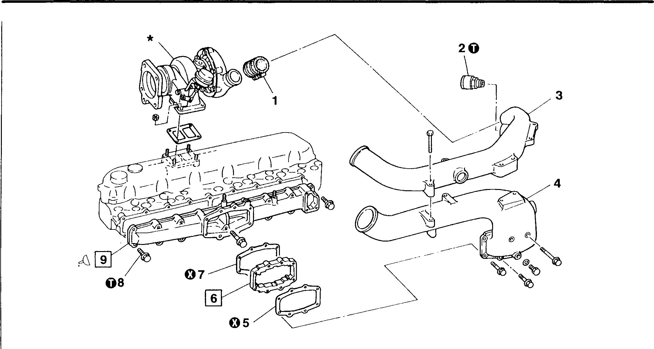
• Disassembly sequence
1 Rubber hose
2 Overboost valve
3 Air inlet pipe
4 Air inlet pipe 5 Gasket 6 Spacer 7 Gasket
• Reassembly sequence
Reverse the order of disassembly.
0
Tightening torque
Location Parts to be tightened
2 Overboost valve
8 Bolt (formounting intake manifold)
� Sealant
Location Points of application
9 Apply to cylinder head mounting surface of the intake manifold
8 Bolt
9 Intake manifold
*: Turbocharger assembly [D P.15-30
0: Non-reusable part
15-58
Tightening torque 31
23
THREE BOND 1207B 18342 Unit: N ·m {kgf·m} RemarksQuantity As required
{3.2}
{2.37} Kinds
♦ Service procedure
[]] Installation of spacer
Thespacer6shouldbeinstalledwithitsarrowmarkAdirectedtowardthe intake manifold 9.
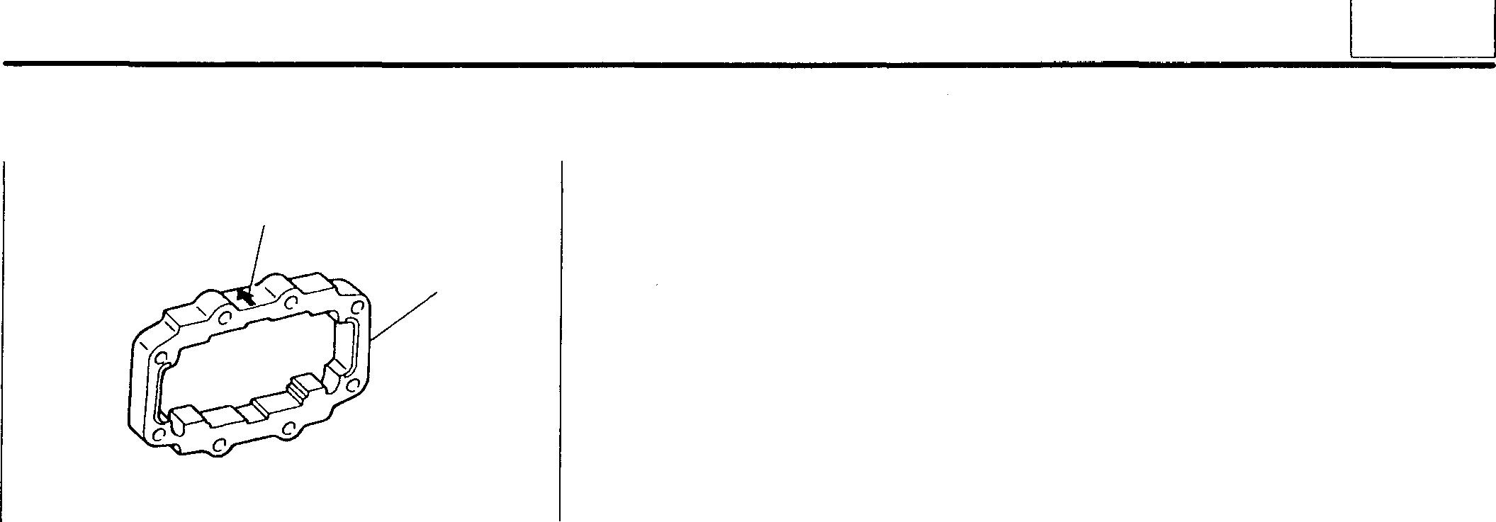
[]] Installation of intake manifold
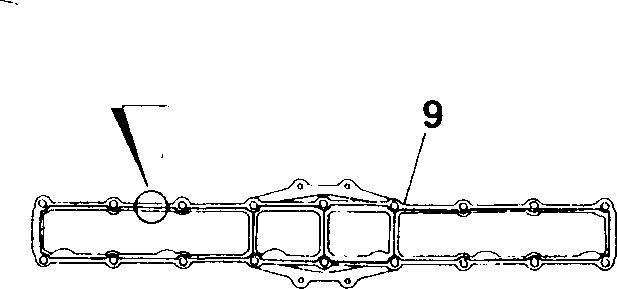
• The intake manifold9isinstalledbyuse ofeitheraseatgasket orsealant. This section describes the procedures for installation by use of a sealant.
• Apply sealant A evenly without a break to the cylinder head mounting surface of the intake manifold 9.
• Install theintake manifold9onthecylinderheadinlessthan three minutes after application of sealant A.
CAUTION&-------------
• Thoroughly clean the sealant applying surface of the intake manifold 9 beforehand.
• Whentheintakemanifold9isinstalled, make surethatitisnotout of alignment.
• When the manifold mounting bolt 8 was loosened, be sure to reapply sealant A to the intake manifold 9.
• Do not start the engine in less than an hour after installation.
A 6 18699 qi 1.5 AT 18339
15
15-59
EXHAUST MANIFOLD 6D16-TLEAEARLY TYPE
• Disassembly sequence
1 Cover
2 Nut
3 Exhaust manifold
4 Gasket
*: Cylinder head u] Gr.11
0: Non-reusable part
• Reassembly sequence
Reverse the order of disassembly.
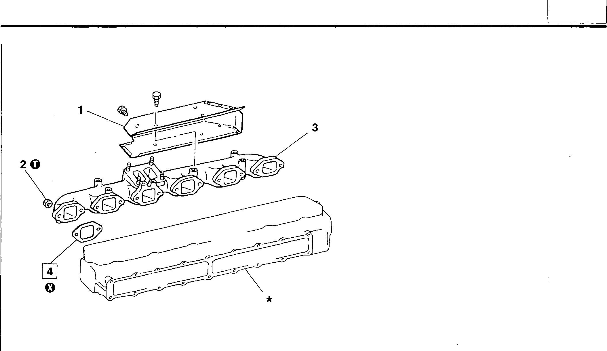
0
Tightening torque
Location
Parts tobetightened
2 Nut (formounting exhaust manifold)
Tightening torque
41 {4.2}
♦ Service procedure
[II Installation of gasket
4
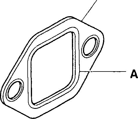
Unit: N·m {kgf·m}
Remarks
Installthegasket4withthegrommetfold-backportionAtowardthecylinderhead.
15
06185 18346
-
15-61
EXHAUST MANIFOLD 6016-TLEALATETYPE
• Disassembly sequence
1 Front insulator
2 Rear insulator
3 Nut
4 Exhaust manifold
5 Gasket
*: Cylinder head [D Gr.11
0: Non-reusable part
• Reassembly sequence
Reverse the order of disassembly.
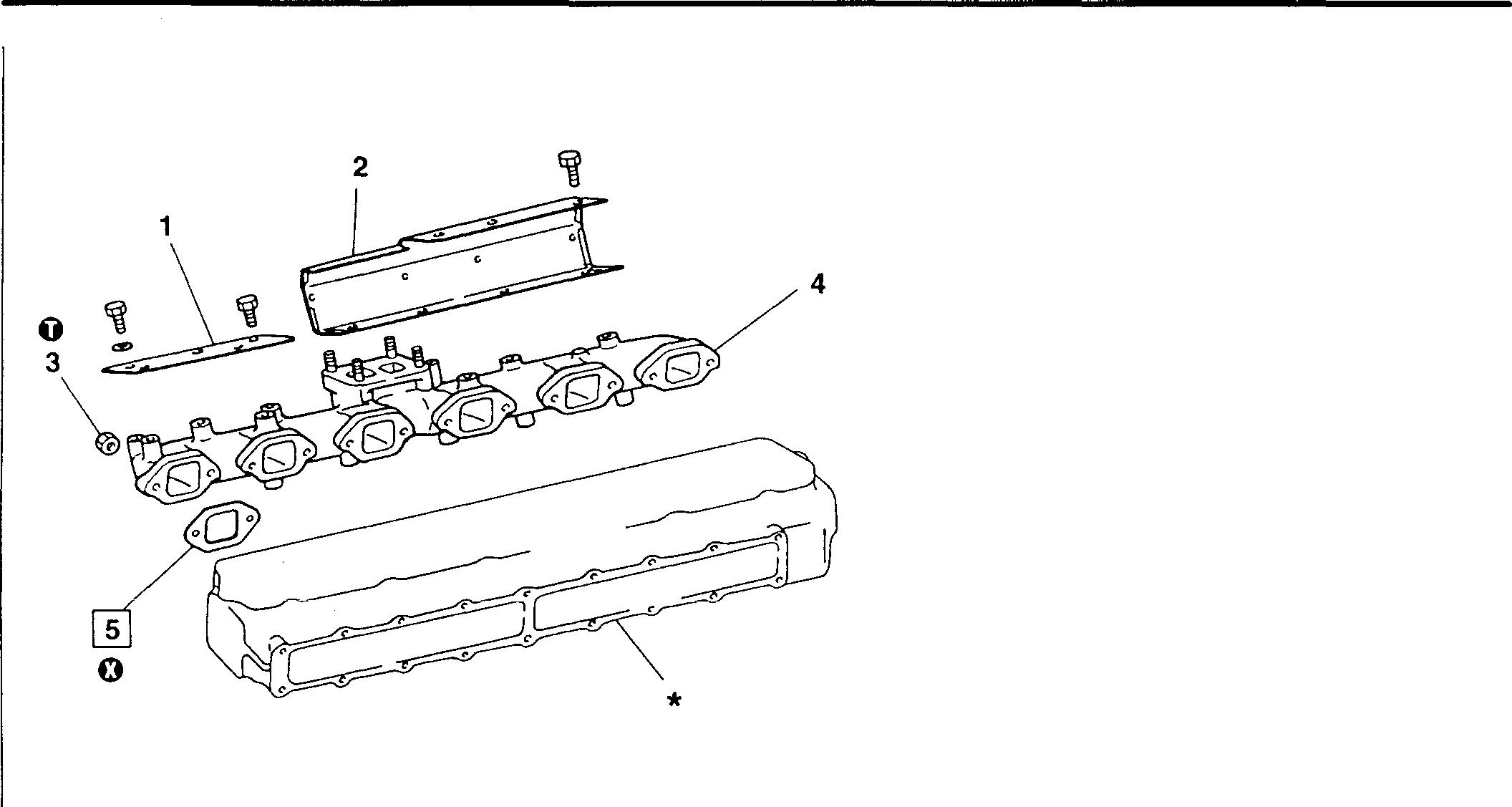
0
Tightening torque
Location
Parts to be tightened
3 Nut (formounting exhaust manifold)
Tightening torque
41 {4.2}
♦ Service procedure
[I] Installation of gasket
5

Unit: N·m {kgf·m}
Remarks -
Installthegasket 5 withthe grommet fold-back portion A towardthecylinder head.
06185 15-62 18347
GROUP 54 ELECTRICAL SYSTEM

SPECIFICATIONS...........................................2 STRUCTUREANDOPERATION..............................3 TROUBLESHOOTING........................................30 ON-VEHICLEINSPECTIONANDADJUSTMENT................32 • Inspection of PreheaterSystem ...........................•......•.. 32 • Inspection of Safety Relay ...............................••......... 32 • Automatic Stop System 37 ALTERNATOR <24V-35A> ................................................•.......... 44 <24V-80A> ....................................................... Deleted <24V-60A> ............................................,.......... Deleted <24V-40A> (withvacuumpump) ................................... Deleted <24V-40A> (withoutvacuum pump) .........................•...... Deleted <24V-90A> ................................................•...... Deleted <12V-80A> ....................................................... Deleted STARTER <24V-5kW> ...............................................•........... 94 <24V-6kW> ...............................................••...... Deleted <12V-5.5kW> .............................................•....... Deleted PREHEATERCIRCUIT.......................................130 ENGINESTARTERCIRCUIT..................................134 AUTOMATICSTOPSYSTEM • Shutdown ..............................................•.......... 136 • Run-on .................................................•.......... 140 54 54-1
SPECIFICATIONS

Item Specifications Alternator Manufacturer MITSUBISHIELECTRICCORP. Type Alternator Alternatorwithbuilt-inregulator,fanexternallymountedtype withbuilt-in regulator, faninternal contacttype Withbrush Brushless Vacuumpump Notprovided Provided Notprovided Model A3TN A6T7 A2T3 A4TU A4T4 I A4T4 A4T7 A4TU 5379 6086 2386 3186 0286 0299 0199 0286 Output (V-A) 24-35 24-80 12-60 24-40 24-90 12-80 Starter Manufacturer MITSUBISHIELECTRICCORP. Model Output(V-kW) 24-5 24-6 12-5.5 Magnetswitch 16orless 8orless operatingvoltage (V) Starter Model relay Excitingcurrent 24-2.3 12-4 (V-A) Closedmagnetic 16orless 8orless voltage(V) Openedmagnetic 4orless 3.5orless voltage(V) Allowablebreaking 200 200 voltage(V) Intakeair Manufacturer HiyoshiDenso heater Voltage-capacity 22-1.83 22-2.9 11-1.83 (V-kW) Fusecapacity (A) - 127Heater Manufacturer relay Model Voltage-current 24-2.3 12-5.2 (V-A) Fusecapacity (A) 91 127Glow Type Sheathedtype plug Voltage-current 23-3 (V-A) Glow Model relay Voltage-current 24-2.3 (V-A) Fusecapacity(A) 127 Safety Model relay Stop Manufacturer KimuraYoko NIPPONDENSO solenoid Kind Shut-downtype Run-ontype Type Electromagnetictype Solenoid Manufacturer NikkoDenki relay Kind Shut-downtype Run-ontype Model 24V 12V 54-2
STRUCTURE AND OPERATION
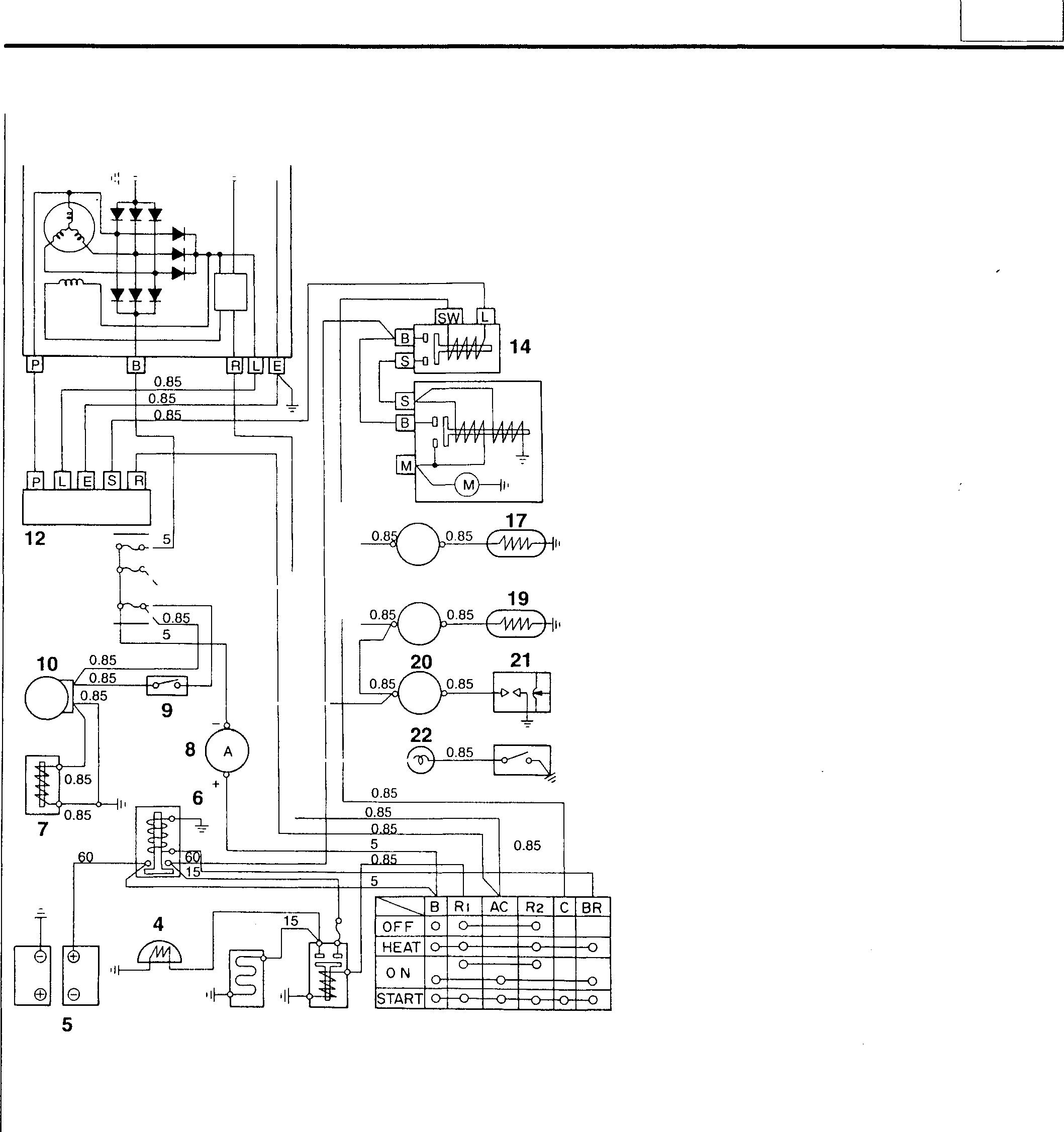
13 0.85 0.85 0.85 11 3 Wiresymbol � � Wireconductorsectionalarea (0.85mmormore) 15 16 18 23 0.85 2 1 18458 1 Starterswitch 2 Heater relay 3 Airheater 4 Heaterindicator 5 Battery 6 Batteryrelay 7 Tachometersensor 8 Ammeter 9 Lampswitch 10 Tachometer 11 Fuse box 12 Safetyrelay 13 Alternator 14 Starter relay 15 Starter 16 Thermometer (foroil) 17 Thermo sending unit 18 Thermometer (for coolant) 19 Thermo sending unit 20 Oilpressure gauge 21 Oil pressure gauge unit 22 Warninglamp 23 Oil bypass alarm switch B:TerminalB E:Terminal E L:Terminal L M:Terminal M P:Terminal P R:Terminal R S:TerminalS SW:Terminal SW 54 54-3
Circuit Diagram <24V (Air Heater) Specification>
STRUCTURE AND OPERATION
Circuit Diagram <24V (Glow Plug) Specification>
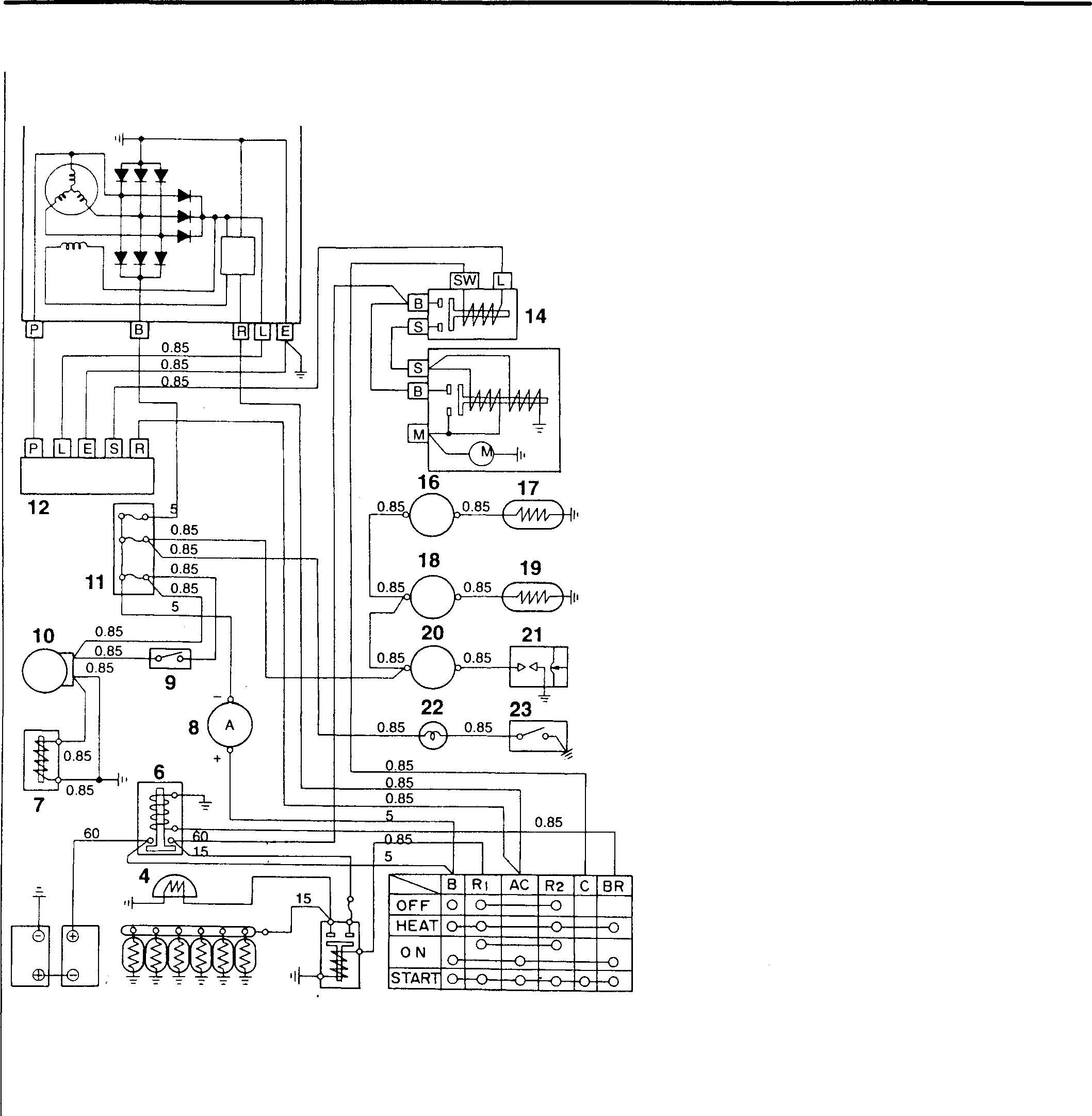
Wiresymbol QJlli � Wireconductorsectionalarea (0.85mmormore)
Terminal M
Terminal P
Terminal R
Terminal S
Terminal SW
13 5 3 54-4
15 2 1 18459 1
2 Glow
3 Glow
4 Glow
5 Battery 6 Battery
7 Tachometer sensor 8 Ammeter 9 Lamp switch 10 Tachometer 11 Fuse box 12 Safety relay 13 Alternator 14 Starter relay 15 Starter 16 Thermometer (for oil) 17 Thermo sending unit 18 Thermometer (for coolant) 19 Thermo sending unit 20 Oil pressure gauge 21 Oil pressure gauge unit 22 Warning lamp 23 Oil bypass alarm switch B:
B E:
E L:
M:
P:
R:
S:
SW:
Starter switch
relay
plug
indicator
relay
Terminal
Terminal
Terminal L
Circuit Diagram <12V Specification>
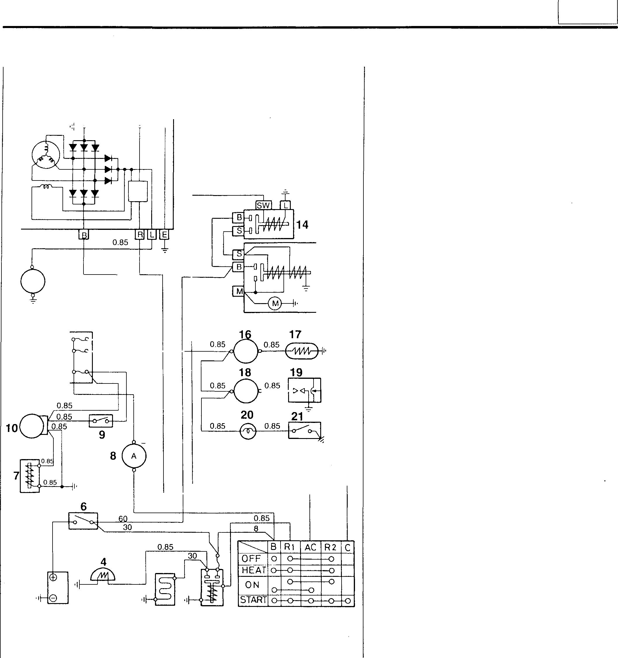
1 Starter switch 2 Heater relay
Airheater
Heater indicator
Battery
Battery switch
Tachometer
sending
pressure gauge
pressure gauge
Warning lamp
Oil bypass alarm switch
54
13 4
5
6
7
sensor 8
9
switch 10 Tachometer 11 Fuse box 12 Hour meter 13 Alternator 14 Starter relay 12 15 15 Starter 16 Thermometer (for
17
unit 18
19
unit 11 20
21
B: Terminal B E: Terminal E L: Terminal L M: Terminal M R: Terminal R + 8 S: Terminal S 2 SW: Terminal SW 8 5 3 2 1 18460 54-5
3
Ammeter
Lamp
coolant)
Thermo
Oil
Oil
STRUCTURE AND OPERATION
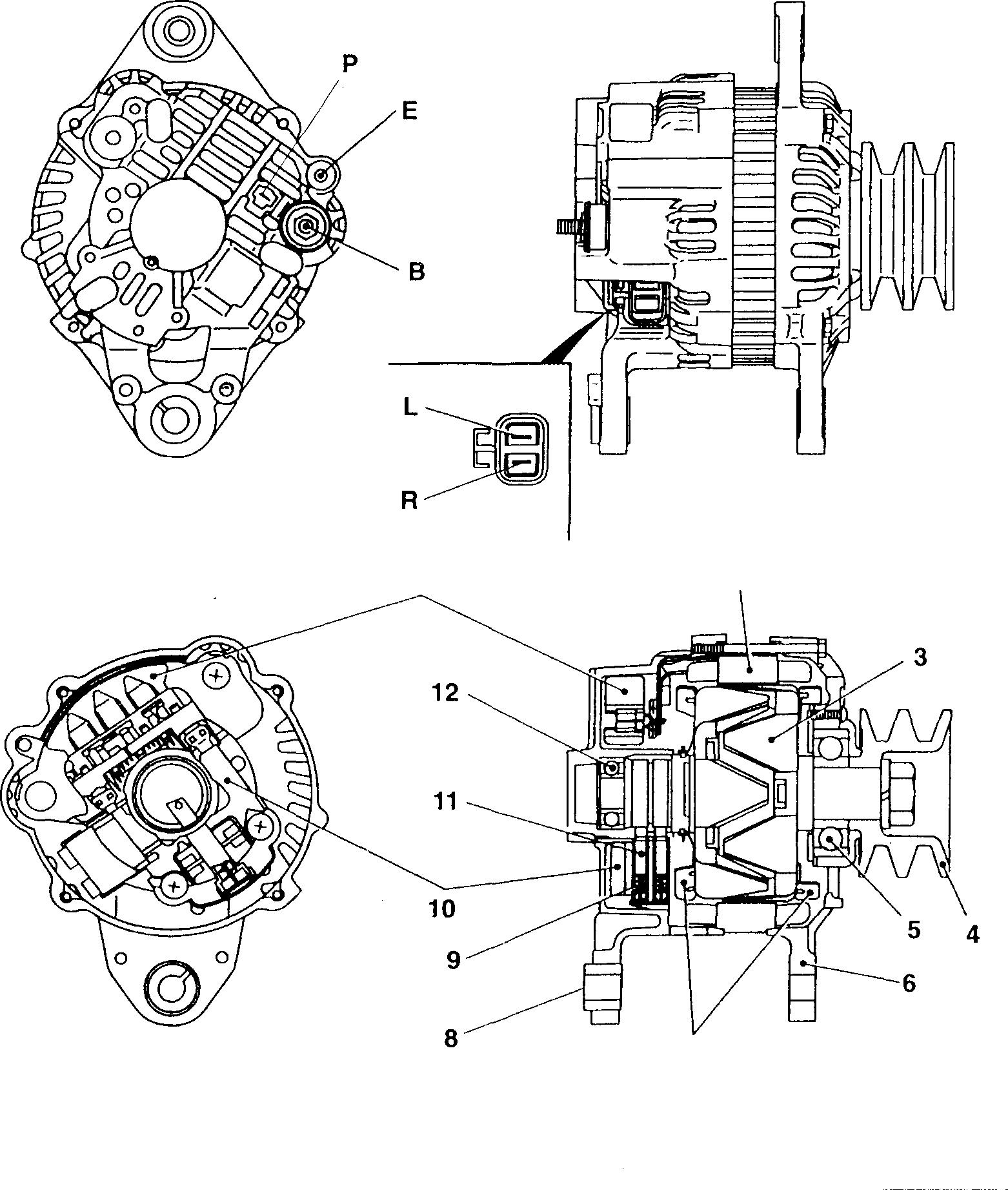
1 Rectifier
Stator assembly
Rotorassembly
Pulley
Front bearing
Front bracket
Alternator <24V-35A>
54-6 1 7 Fan 8 Rear bracket 9 Brush spring 10 Regulator & brush holder 11 Brush 12 Rearbearing 2 7 16742 B:Terminal B E:Terminal E L:Terminal L P:Terminal P R:Terminal R
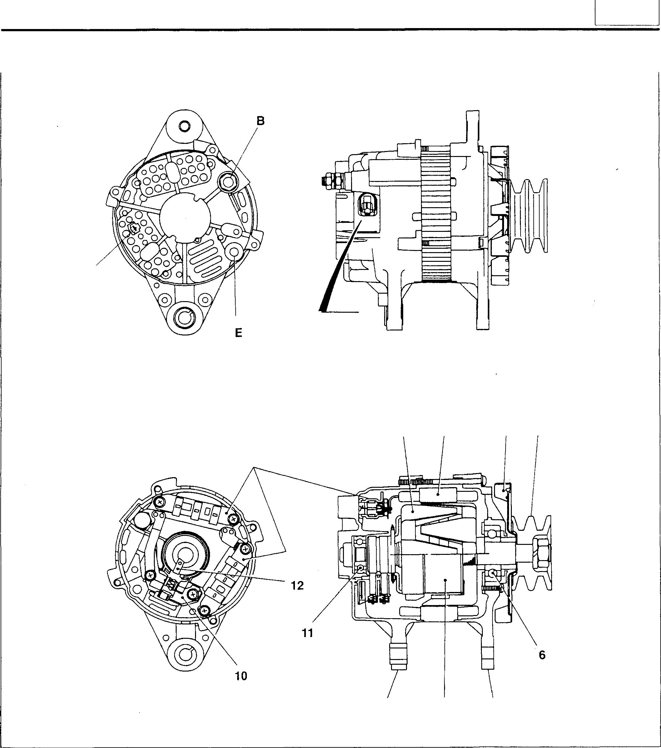
54 <24V-80A> p A�L 2 3 4 5 1 9 8 7 10625 1 Rectifier 7 Frontbracket B:Terminal B 2 Rotor assembly 8 Field coil E:Terminal E Stator assembly 9 Rearbracket L:Terminal L Fan 10 Regulator P:Terminal P Pulley 11 Rear bearing R:Terminal R Frontbearing 12 Brush 54-7
STRUCTURE AND OPERATION
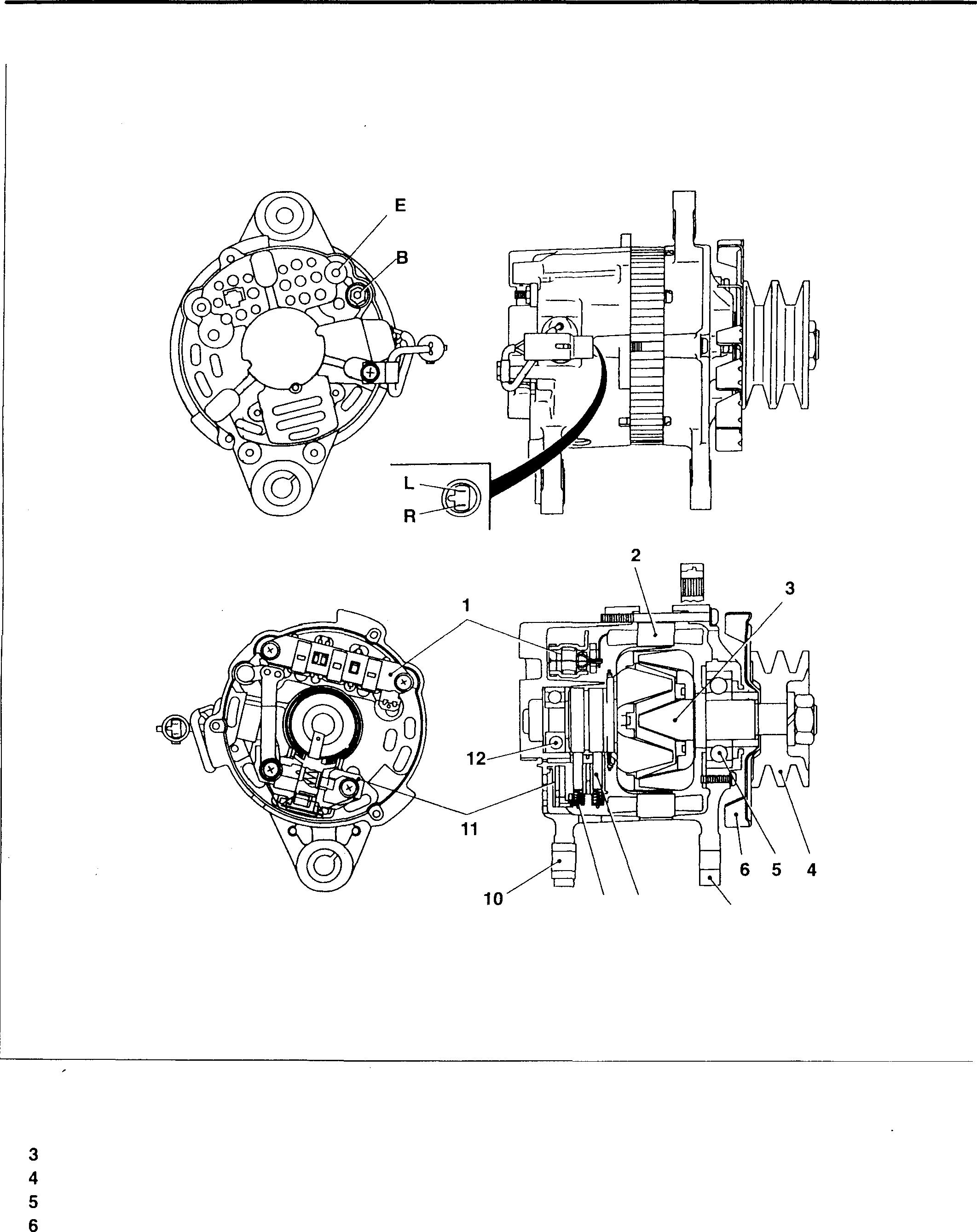
1 Rectifier 7 Front bracket 2 Stator assembly 8 Brush Rotor assembly 9 Brush spring Pulley 10 Rear bracket Front bearing 11 Regular & brush holder Fan 12 Rear bearing 54-8 9 8 7 B: Terminal B E: Terminal E L: Terminal L R: Terminal R 16743
<12V-60A>
<24V-40A (with vacuum pump)>
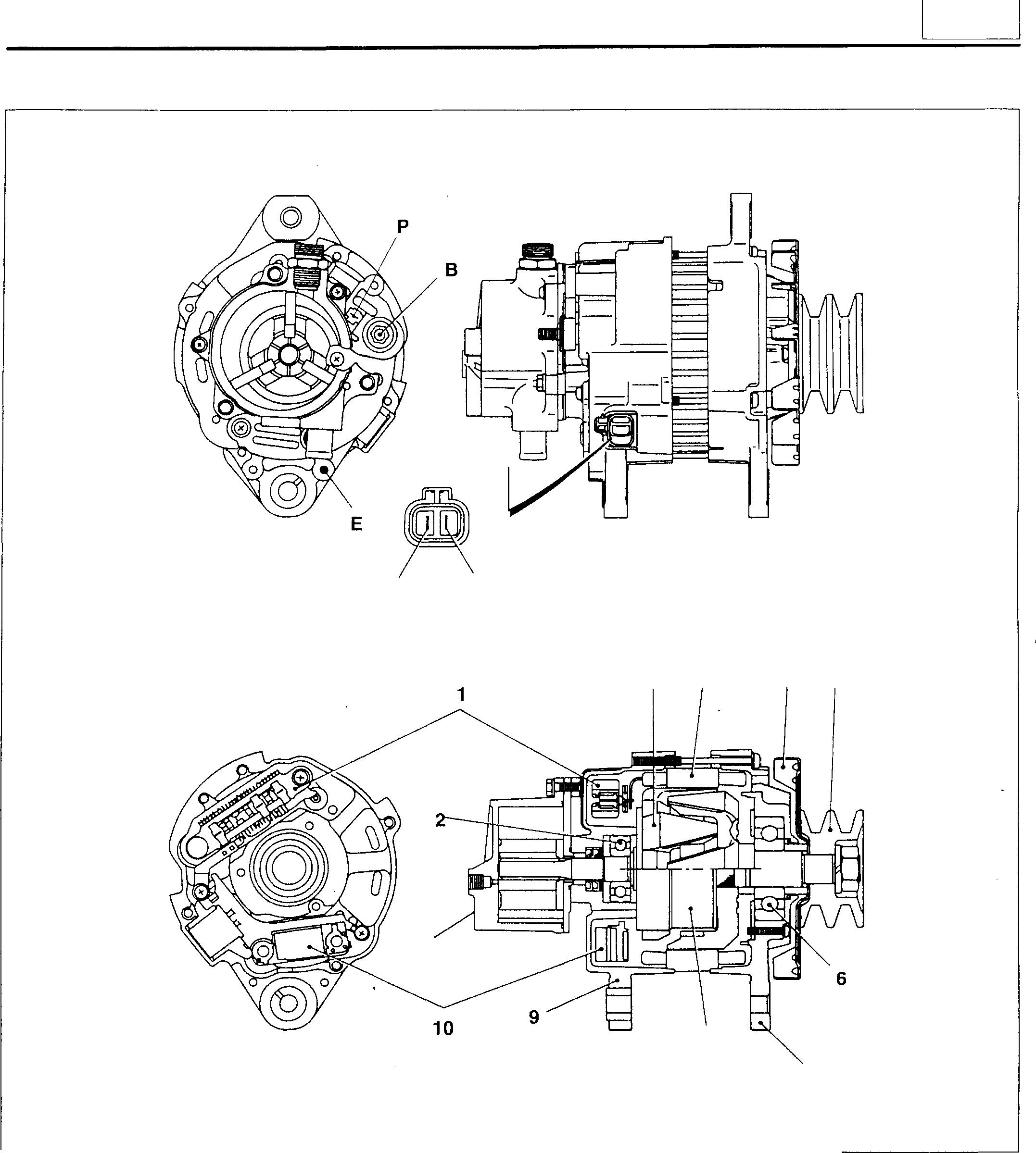
1 Rectifier 7 2 Rotor assembly 8 3 Stator assembly 9 4 Fan 10 Pulley 11 Front bearing 12 R L 1 11 Front bracket Field coil Rear bracket Regulator Vacuum pump Rear bearing 54 2 3 4 5 8 7 09431 B: Terminal B E: Terminal E L: Terminal L P: Terminal P R: Terminal R 54-9
STRUCTURE AND OPERATION
<24V-40A (without vacuum pump), 12V-80A>
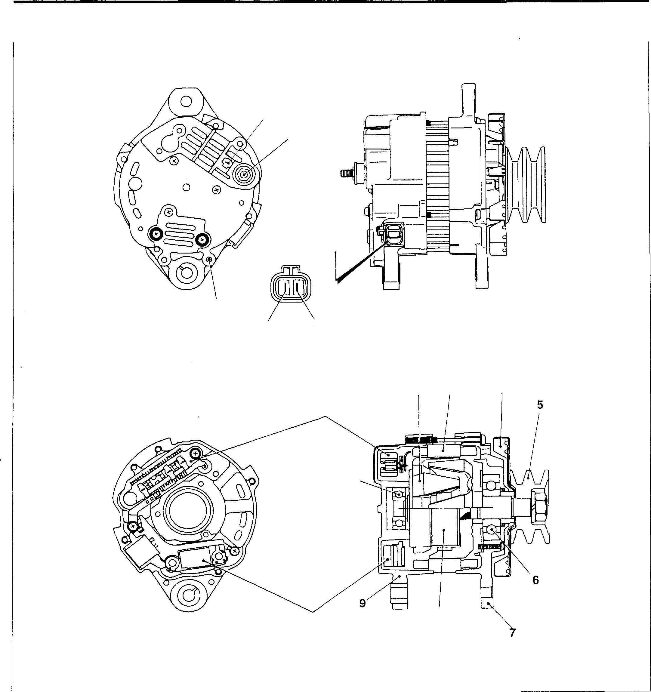
E 1 Rectifier 7 2 Rotor assembly 8 Statorassembly 9 Fan 10 Pulley 11 Front bearing 54-10 p 8 R L 1 10 Front bracket Field coil Rear bracket Regulator Rear bearing 11 2 3 4 8 08644 B:Terminal B E: Terminal E L:Terminal L P: Terminal P R:Terminal R
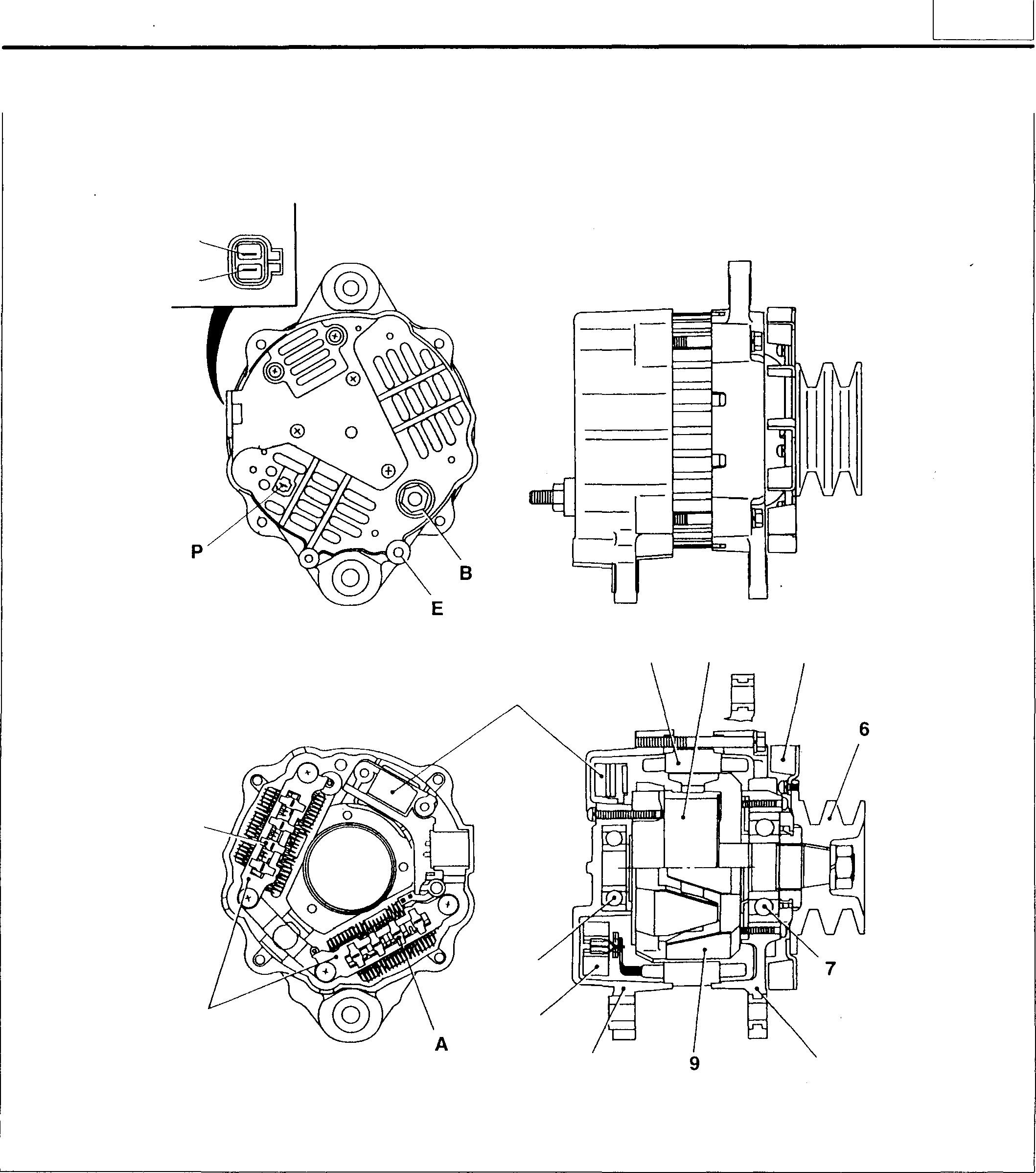
R L A 1
4
5
2 11 1 7 Front bearing 8 Frontbracket 9 Rotor assembly 10 Rear bracket 11 Rear bearing A: Neutral
54 3 4 5 10 8 16744 8:Terminal B E:Terminal E L:Terminal L P: Terminal P R: Terminal R 54-11
<24V-90A> 1 Rectifier 2 Regulator
Stator assembly
Fieldcoil
Fan Pulley
pointdiode
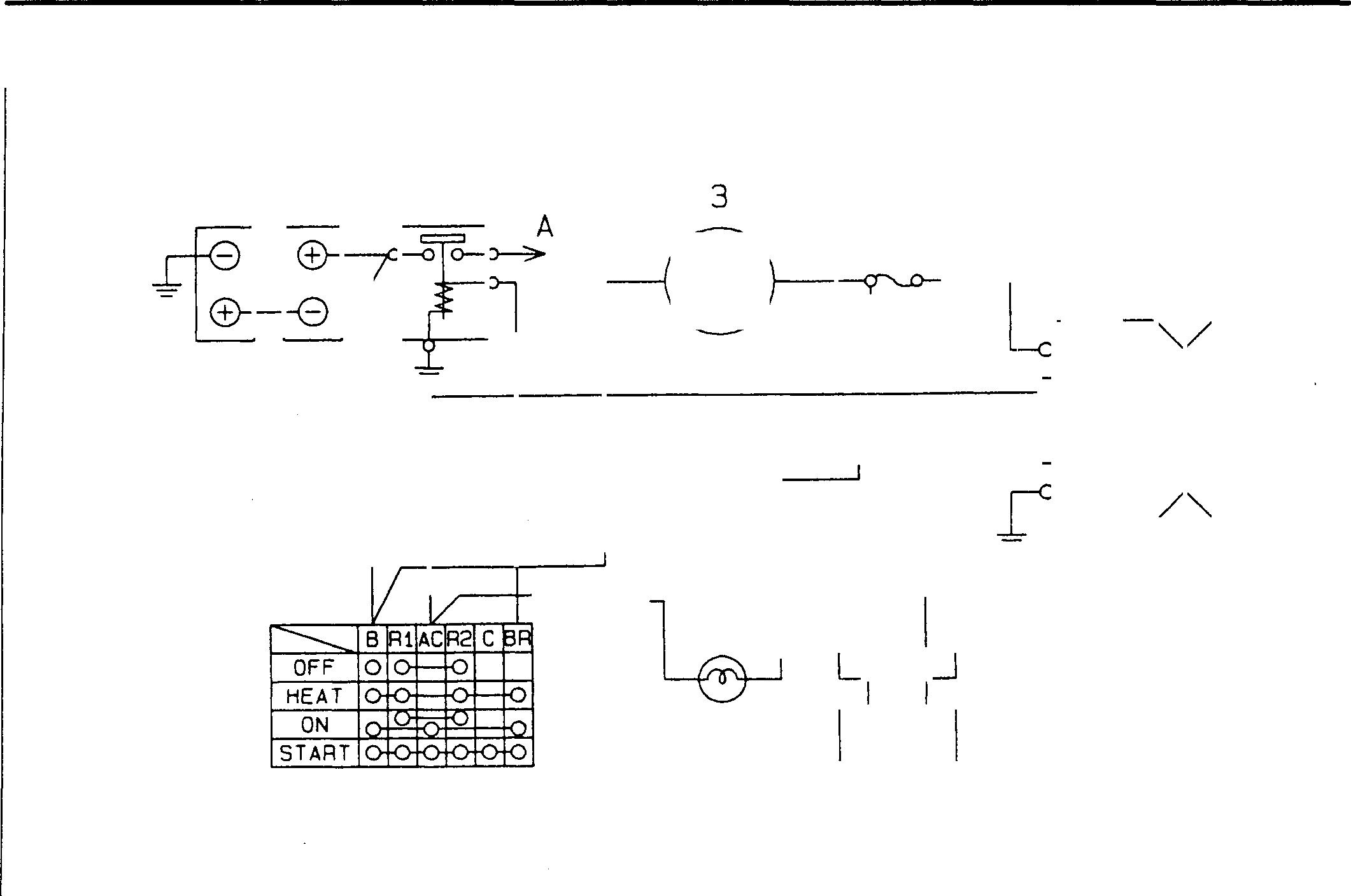
Charging Circuit 1 Battery 2 Batteryrelay 3 Ammeter 4 Fuse box 5 Alternator 1 28 6 Safety relay <Circuitwithoutchargelamp> 7 Chargelamp <Circuitwithchargelamp> 8 Starterswitch 54-12 <BmG 4 � 7 L R<With charge lamp> 6 <Without charge lamp> A: Tostarter relay terminal B B:Terminal B E:Terminal E L:Terminal L R: Terminal R 5 B R L E 16739
STRUCTURE AND OPERATION
7
<With charge 6 lamp> <Without charge lamp>
When engine is stationary
Position of starter switch 8: ON
• To improve the performance of the alternator 5 in starting power generation at a low speed immediately after the engine has been started, current is set flowing to terminal R.
1 ➔ 2 ➔ 8t 5 (R ➔ E) ➔ Earth 6 (R ➔ L) ➔ 5 (L ➔ E) ➔ Earth
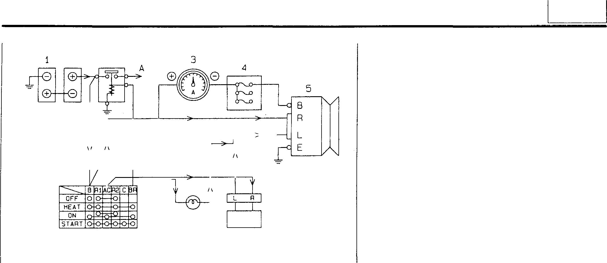
• In the circuit with A charge lamp 7, current flows as shown below.
1 ➔ 2 ➔ 8t 5 (R ➔ E) ➔ Earth 7 ➔ 5 (L ➔ E) ➔ Earth
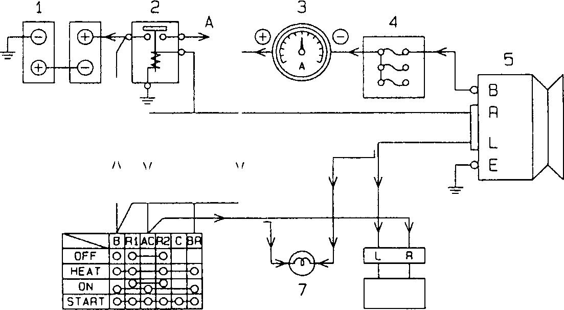
<With charge 6 lamp> <Without charge lamp>
After engine has been started
Position of starter switch 8: ON
• The alternator 5 starts generating power.
• Theoutput voltageatterminal B of thealternator 5 becomes higher than the voltage of the battery 1.
• The alternator 5 startscharging the battery 1.
5 (8) ➔ 4 ➔ 3 ➔ 8 ➔ 2 ➔ 1
• In the case of the circuit with the charge lamp 7, the charge lamp goes out, as there is no potential difference between the voltage at terminal L of the alternator 5 and the battery voltage.
2 8 8
16740 16741
54
54-13
STRUCTURE AND OPERATION
• Alternator with neutral point diode
Effectiveness of alternator with neutral point diode
The point where three stator coils A are coupled is called the neutralpointC. Additionoftwodiodes Dtothecurrentalternator whichusessixdiodesmakesitpossibleto provideahigherDC output than an alternatorwithoutneutral point diodes.
B: Alternatorterminal B
E: Alternatorterminal E
F: IC regulator
L: Alternatorterminal L
R: Alternatorterminal R
Variations in potential at neutral point, and operation of neutral point diode
• The potential at the neutral point C varies up and down as shownwiththeneutralpointDCvoltage (onehalfoftheoutput voltage) as the center. When the alternator rotates at a very high speed, the peak values of the potential by far exceed the outputvoltage. (28V or more, OV orless)
G: Duringhigh speed rotation
H: During lowspeed rotation
J: Neutral point voltage waveform
K: Outputvoltage
L: Mean voltage atneutral point
M: Ground potential
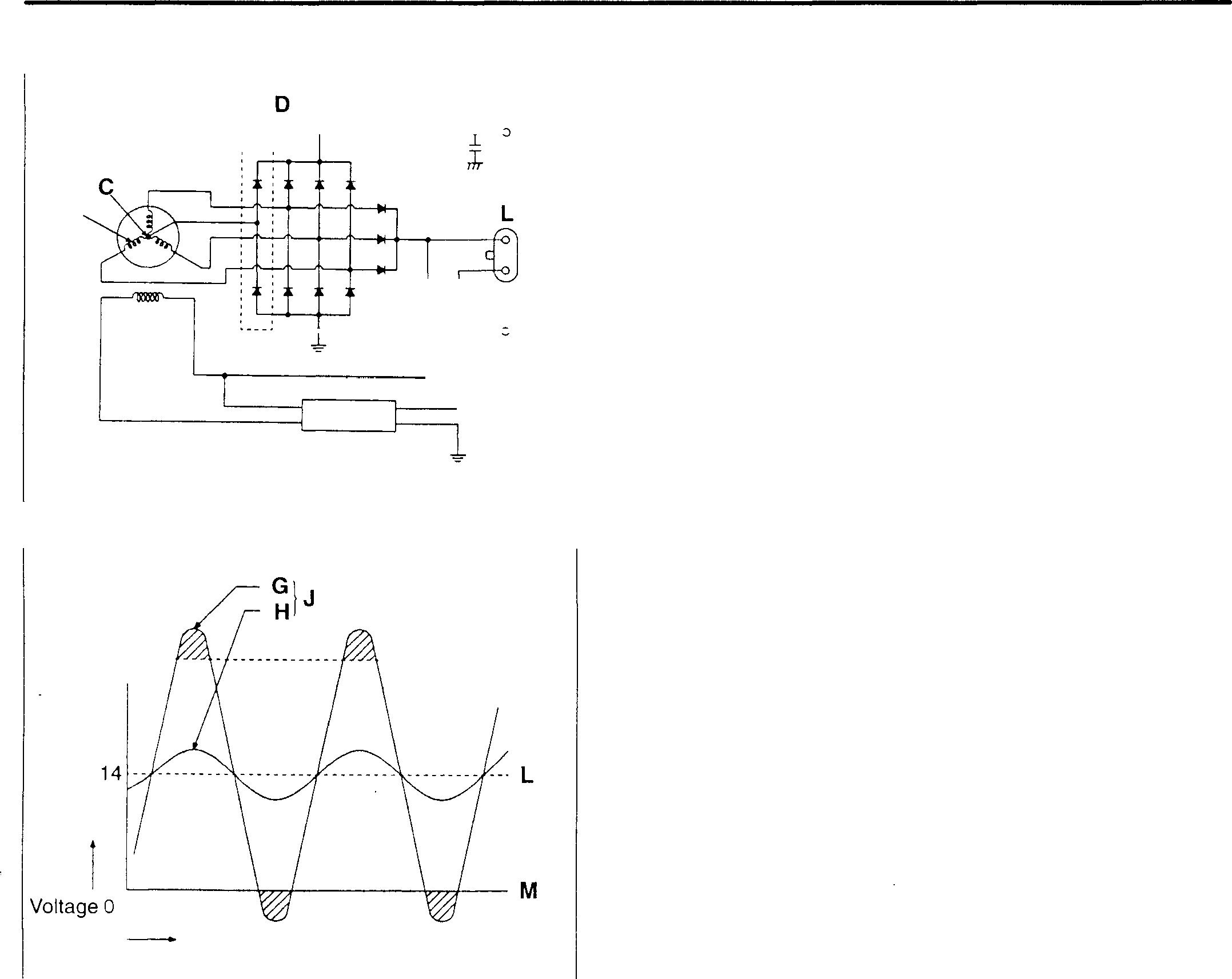
In each of the voltage and potential conditions, the neutral point diode operates as described below.
• WhentheneutralpointvoltageismorethanOVandlessthan 28V, the six conventional diodes operate.
..
B A R E F 07033 (V) 28 ..... K Turning angle 07400 54-14
I
• When the neutral point voltage is more than 28V
The positive side diode N conducts to add to the conventional DC output, so ahigher DC voltage is outputtoeachequipment.
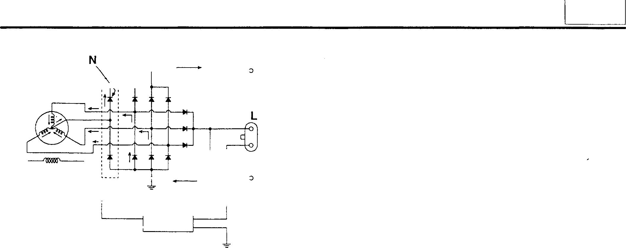
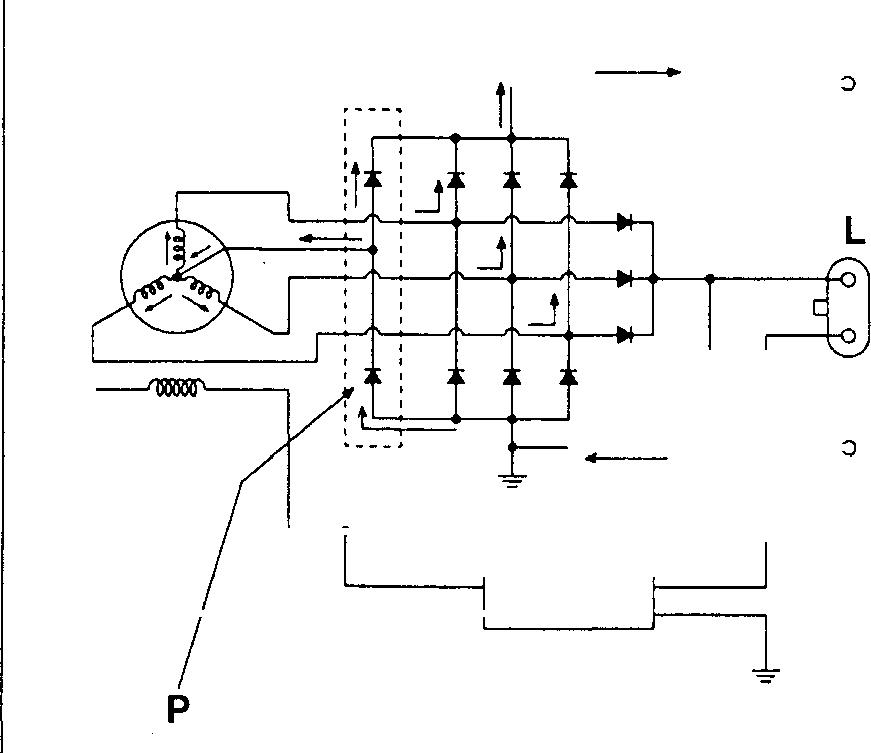
• When the neutral point voltage is less than OV
The negative side diode P conducts, and the neutral point output is supplied via the three conventional diodes.
8 :--; __J tl A E 07034 8 A E 07035 54
54-15
STRUCTURE AND OPERATION
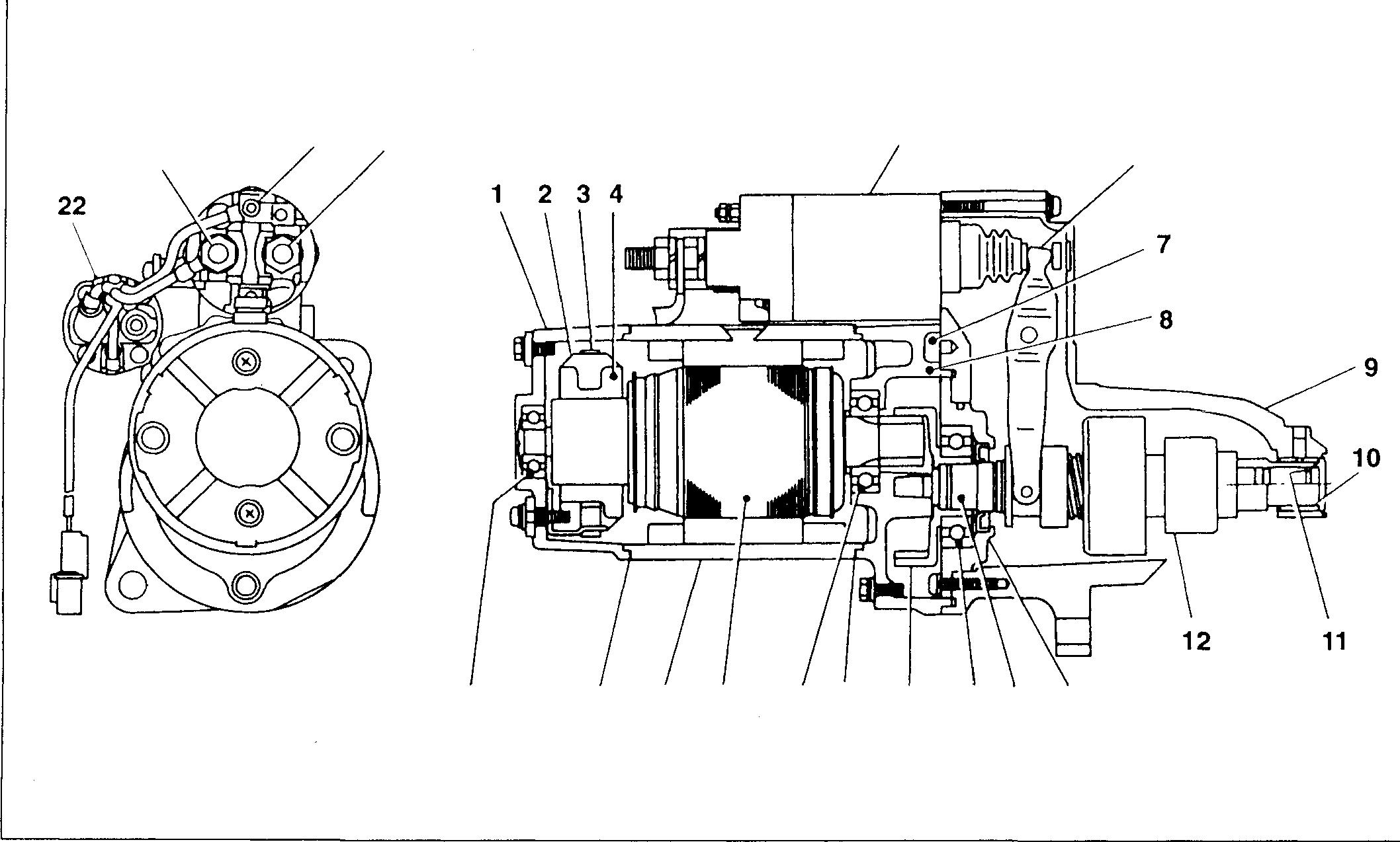
Starter <24V-6kW> B 1 Rear bracket 2 Brush 3 Brush spring s 4 Brush holder assembly 5 Magnetswitch 6 Lever 7 Guide 8 Centerbracket 9 Front bracket 10 Sleeve bearing 11 Stopperring 12 Overrunningclutch 13 Gear bracket 54-16 M 5 21 172019181716151413 14 Gearshaft 15 Gearshaft bearing 16 Internalgear 17 Rubberpacking 18 Frontbearing 19 Armature 20 Yokeassembly 21 Rearbearing 22 Starterrelay B:Terminal B M: Terminal M S: Terminal S 6 18987
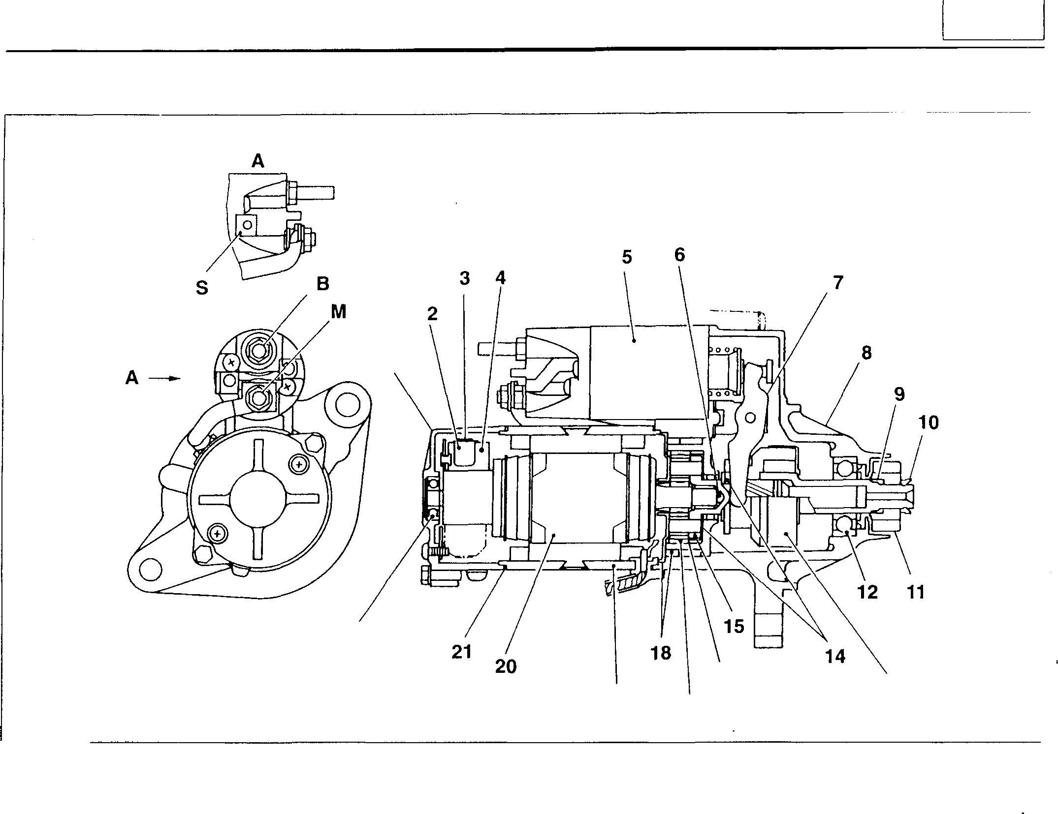
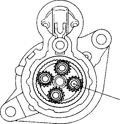
54 <24V-5kW> 1 22 16 13 19 17 10739 1 Rear bracket 10 Pinion stopper 19 Yoke assembly 2 Brush 11 Pinion 20 Armature assembly 3 Brush spring 12 Front bearing 21 Packing 4 Brush holder assembly 13 Overrunning clutch 22 Rear bearing 5 Magnet switch 14 Washer 6 Ball 15 Gearshaft assembly B: Terminal B 7 Lever 16 Internal gear assembly M: Terminal M 8 Front bracket 17 Planetary gear S: Terminal S 9 Spring 18 Packing This starter uses planetary gear 17 in the reduction gear mechanism. 17 13501 54-17
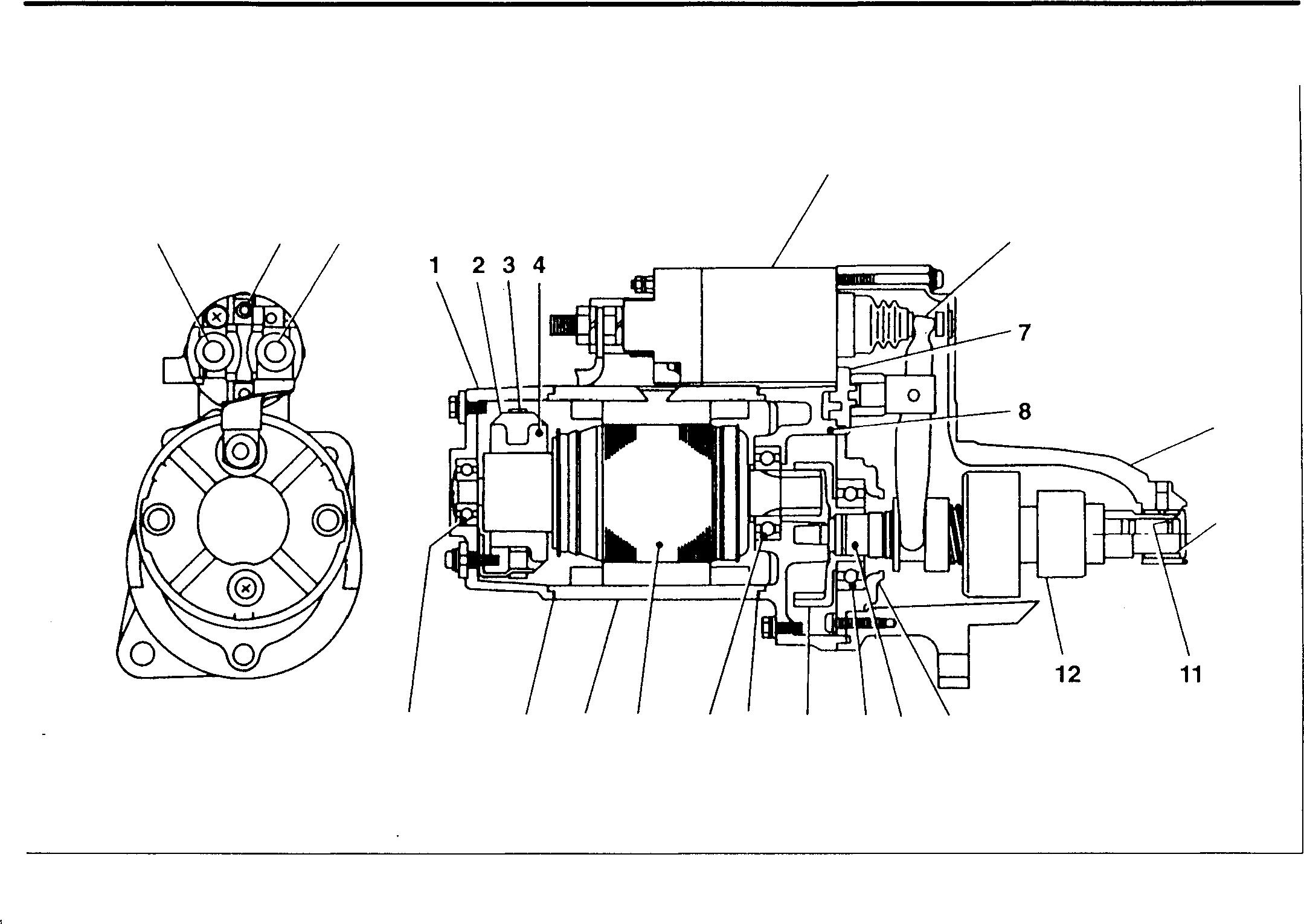
<12V-5.5kW> 1 2 3 4 5 6 7 8 9 10 11 12 13 B Rear bracket Brush Brush spring S M Brush holder assembly Magnet switch Lever Rubberpacking Center bracket Front bracket Sleeve bearing Stopper ring Overrunningclutch Gear bracket 54-18 21 17 20 19 5 6 9 10 18 17 16 15 14 13 10847 14 Gearshaft 15 Gearshaft bearing 16 Internal gear 17 Rubberpacking 18 Front bearing 19 Armature 20 Yokeassembly 21 Rear bearing B:Terminal B M: Terminal M S: Terminal S
STRUCTURE AND OPERATION
Preheating Circuit
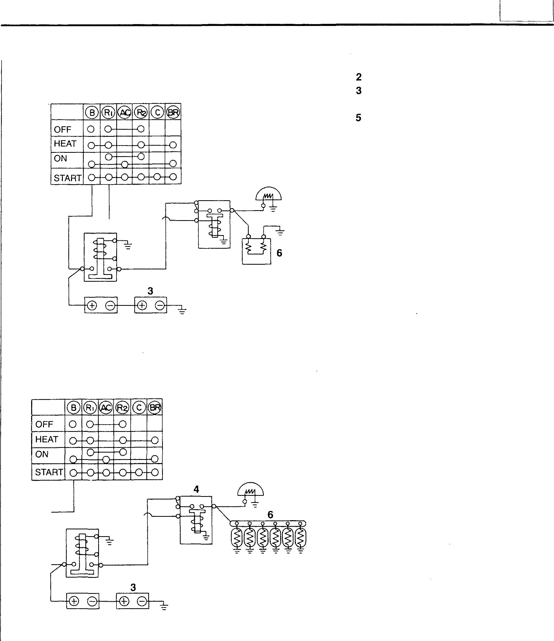
<GlowPlug>
1 Starter switch
54
1
5 4 2 18461
<Intake Air Heater> Battery relay Battery 4 Heater relay Heater indicator Glowindicator
6 Intake air heater Glowplug
1 5 2 18462 54-19
STRUCTURE AND OPERATION
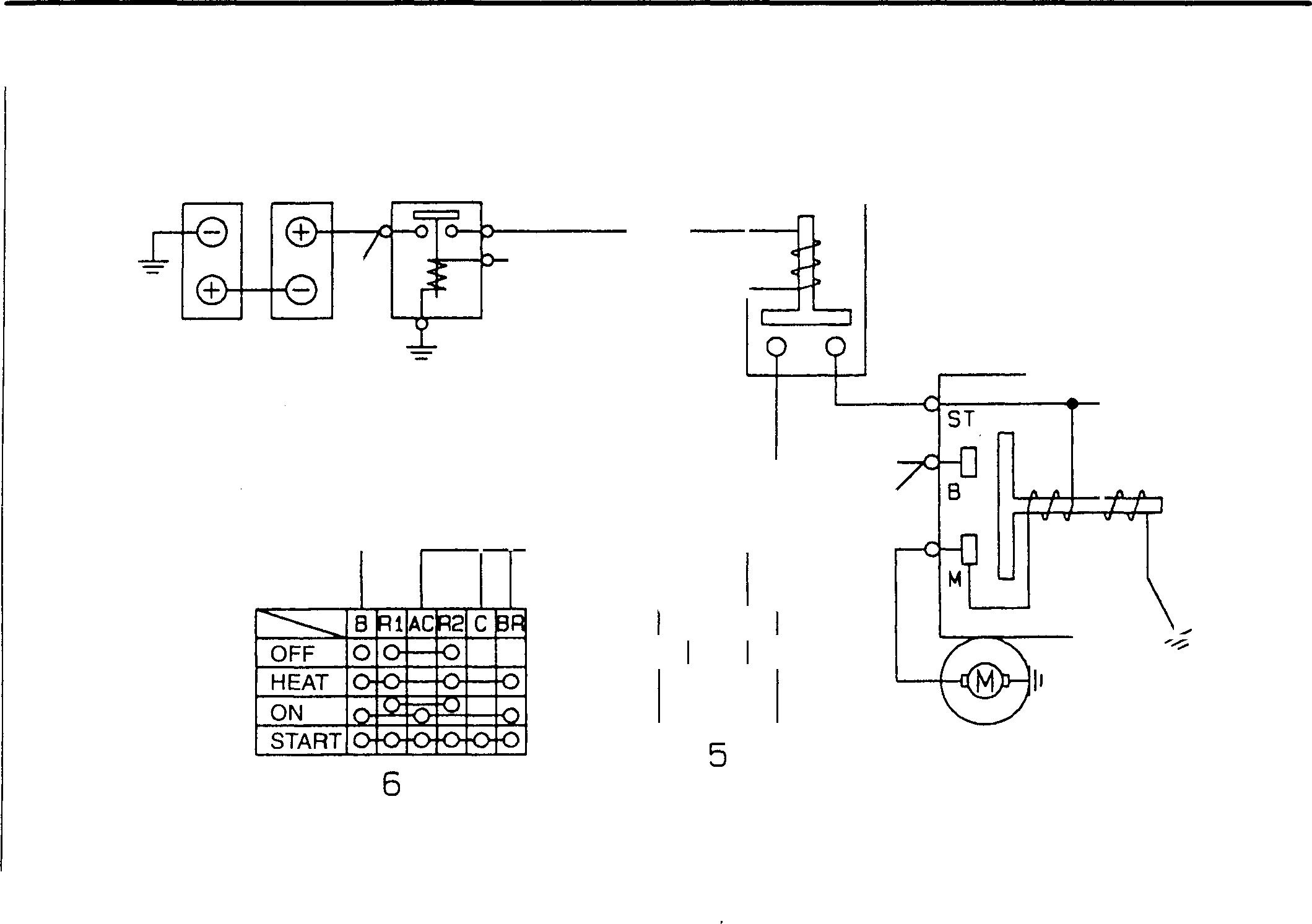
1
2
3
4
1 5
6
54-20 2 3 4 s R 16757
Engine Starter Circuit
Battery
Battery relay
Starter relay
Starter
Safetyrelay
Starterswitch
The safety relay detects the rotating speed of the alternator. When the rotating speed exceeds the reference value, the safety relay keeps the starterinoperativeevenifthestarterswitch is accidentally set toONwhile the engine is running.
Terminal P
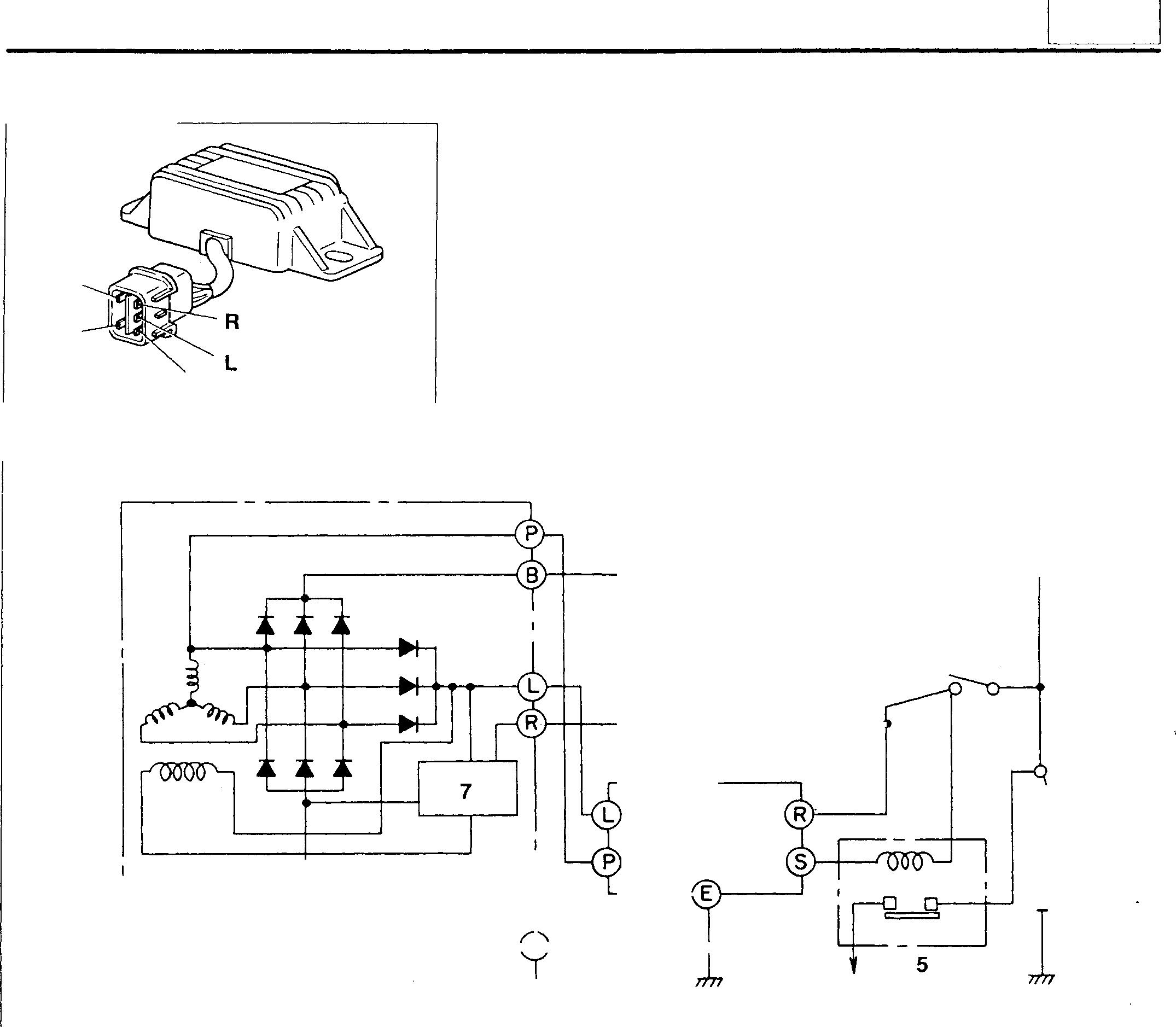
1 Alternator
Starter switch
Battery switch
Starter relay
Safety relay
• When the starter switch 2 is set to ON, current flows from the starter relay 5 through terminal S of the safety relay 6 to terminal E, and contact P1 closes.
• When rotationof the starter causestheengine to start running, pulseswitha frequency of atenth of the alternator speed are generated at terminal P of the alternator 1.
• Whenthe pulsefrequency atterminal P ofthealternator 1 exceedsthereferencevalue, the continuitybetweenterminals S and E is lost, and the starter remains inoperative even if the starter switch 2 is set to ON while the engine is running.
Mitsubishi 6D16TLEA engine parts contact:
email: engineparts2@gmail.com
Phone: 269 673 1638
Text: 269 760 8652
Relay p E 1 s 17530 54
Safety
P:
R:
L: Terminal L S: Terminal S E: Terminal E 6 2 r L_�---E1 4
5
6
7
A A:
B 17531
Terminal R
2
3
4 Battery
IC regulator
To starter terminal
54-21
1 Battery
2 Starter switch
3 Battery relay
4 Stop switch
5 Solenoid relay
6 Solenoid
7 Engine oil pressure switch
8 Stop lever
9 Injection pump governor
10 Water temperature sensor
®: Engine stop signal
®: Hydraulic pressure detection signal
©: Solenoid drive signal
@: Coolant temperature detection signal
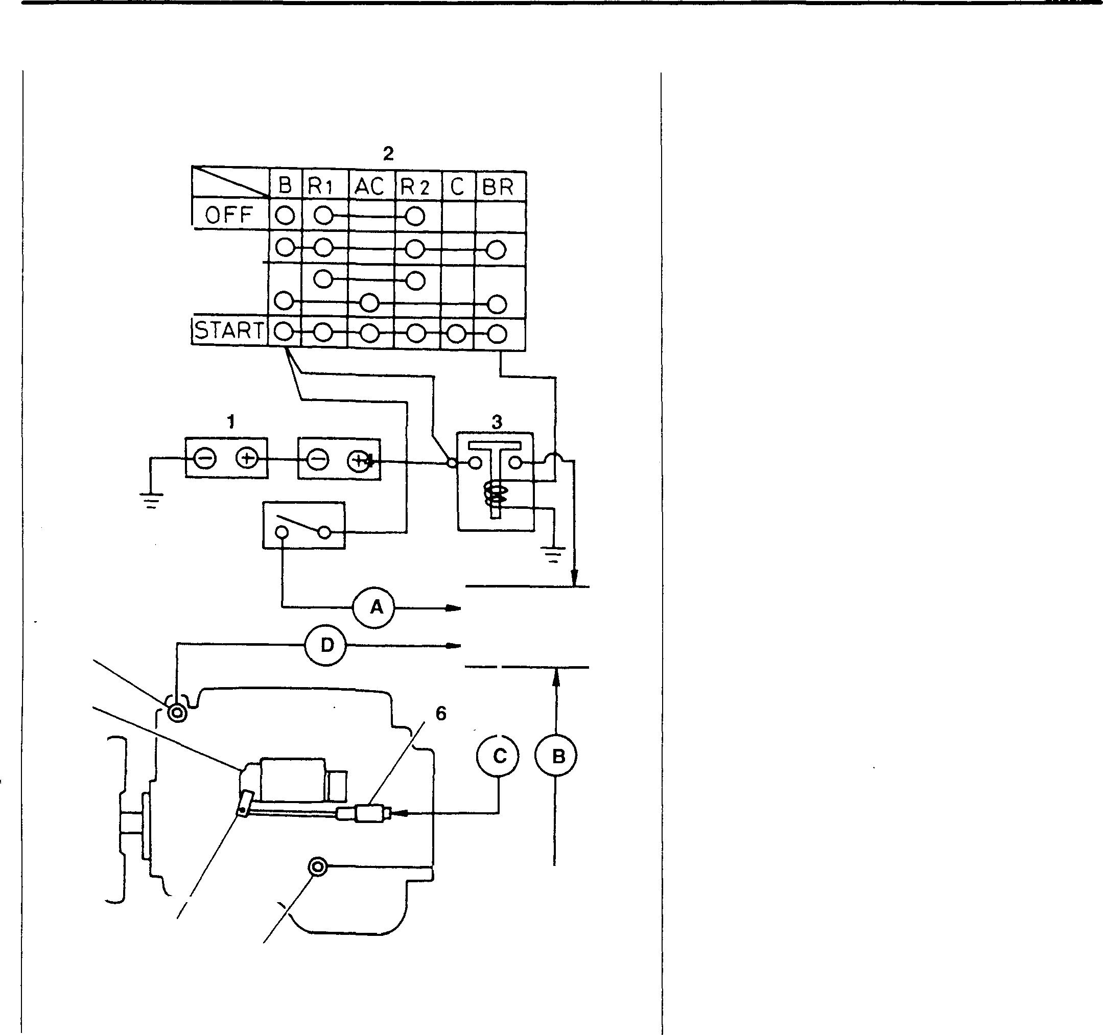
When the oil pressure becomes abnormal or when the coolant temperature abnormally rises while the engine is running, the automatic stop system automatically stops the engine. When anything wrong occurs in the oil pressure or coolant temperature, it is detected by the engine oil pressureswitch 7 or water temperature sensor 10 which operates the solenoid relay 5. As a result, the solenoid 6 moves the stop lever 8 of the injection pump governor 9 in the direction A that the engine stops, thereby stopping the engine. The system comes in two types; the shutdown type and run-on type.
Mitsubishi 6D16TLEA Automatic Stop System 10 9 8 HEAT ON 4 7 5 18736
STRUCTURE AND OPERATION
54-22 Mitsubishi 6D16TLEA engine parts contact: email: engineparts2@gmail.com Phone: 269 673 1638 Text: 269 760 8652
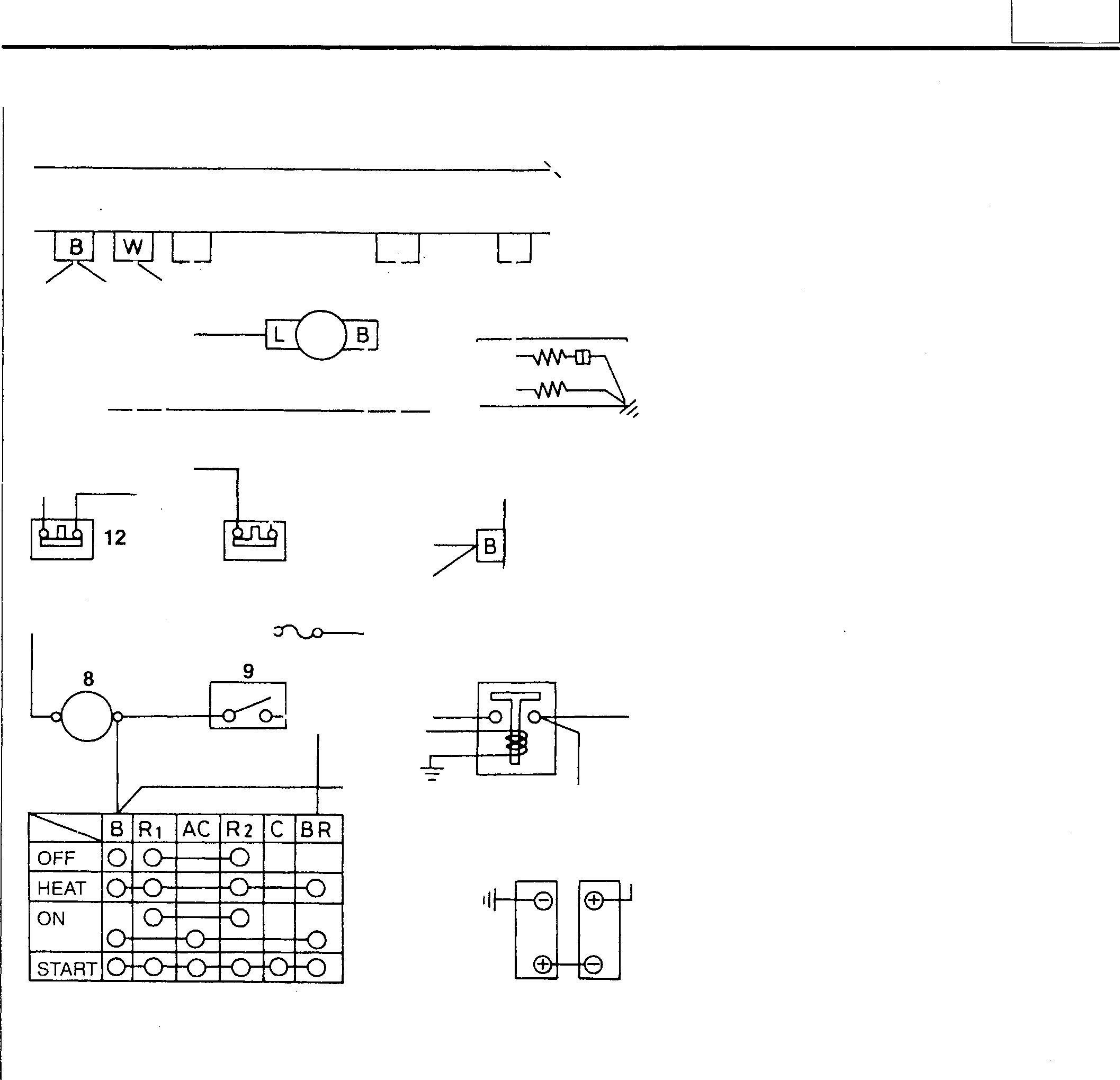
• Onnormalcondition,solenoid 3 isnotenergizedandthestop leverAoftheinjectorpump governor isatthedrivesideBto keep theengine in running condition.
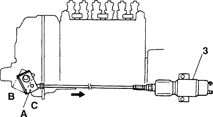
• Whenatroubleoccurs, solenoid 3 isenergizedandpullsthe stop lever A to the stop side C to stop the engine.
< Mitsubishi 6D16TLEA Engine Shutdown> 1 A ST C 2 11 10 5 7 18738 54 1 Solenoid relay 2 Alternator � 3 Solenoid 4 Starter 5 Battery relay 6 Battery 7 Starter switch 8 Ammeter 3 9 Stop switch 10 Fuse box 11 Engine oil pressure switch 12 Coolant temperature sensor 4 6 18737
54-23 Mitsubishi 6D16TLEA engine parts contact: email: engineparts2@gmail.com Phone: 269 673 1638 Text: 269 760 8652
STRUCTURE AND OPERATION
Before engine starts
• Positionof starter switch 7: ON
6➔ 5 -r 7 (B➔ BR)➔ 5 (coil)➔ Earth
4 4 (B)➔1 (8)➔11➔ 1 (W)➔ Earth
• Sincenogeneratedvoltagefromthealternator2isavailableatterminal Aof thesolenoid relay, thesolenoid relay 1 remains inoperative, and nocurrentissupplied tothesolenoid3. Therefore, thestopleverAof the injection pump governor staysatthe position C wherethe engine can bestarted.
When engine starts
• Positionof starter switch7: START
Whenthe engine is started, the generatedvoltagefromthe alternator 2 isappliedtoterminal Aofthesolenoidrelay 1. Atthispoint, theoilpressure is still low. Therefore, the contact of the oil pressure switch 11 remainsclosed,andcurrentflowstoterminalWofthesolenoidrelay 1 to actuate the solenoid relay. In the solenoid relay, however, the voltage appliedtoterminalAisaccumulatedinthecapacitor,sothecurrentdoes notimmediately flowtotheoperatingcircuitintherelay, therebydelaying the timethe solenoidrelay isactuated.
Duringtheperiod, theengineoilpressurerises,andthecontactoftheoil pressureswitchopens to stopthe supply ofcurrenttoterminalW ofthe solenoidrelay, making thesolenoidrelay completely inactive..

4 7 18739 A� 111 C �·�b:£ 18740 18741 54-24
When engine isautomatically stopped
• When the oil pressure abnormally falls or the coolant temperature abnormallyriseswhiletheengineisrunning, engineoilpressureswitch 11 orcoolanttemperaturesensor(thermoswitch)12turnsonandcurrentflowsas described below.
6➔ 5 T 7 (B➔ BR)➔ 5 (coil)➔ Earth
½ 4 (8)➔ 1 (8) T 11➔ 1 (W)➔ Earth
• Atthispoint, thecurrentfromterminalAofthesolenoidrelay1 isflowingtheinternalcircuit, theswitchinthe relayisactivated andthe currentflows as follows:
1 (8)➔ Internalswitchof the relay➔ 1 (C)➔ 3➔ Earth
• Asaresult,solenoid3isactivatedandpullsthestopleverAindirection D to stoptheengine.
• Evenafterlosingthegeneratingvoltagefromthealternator2,theinternalcapacitor of the solenoid relay1 keeps the solenoid 3 in position.
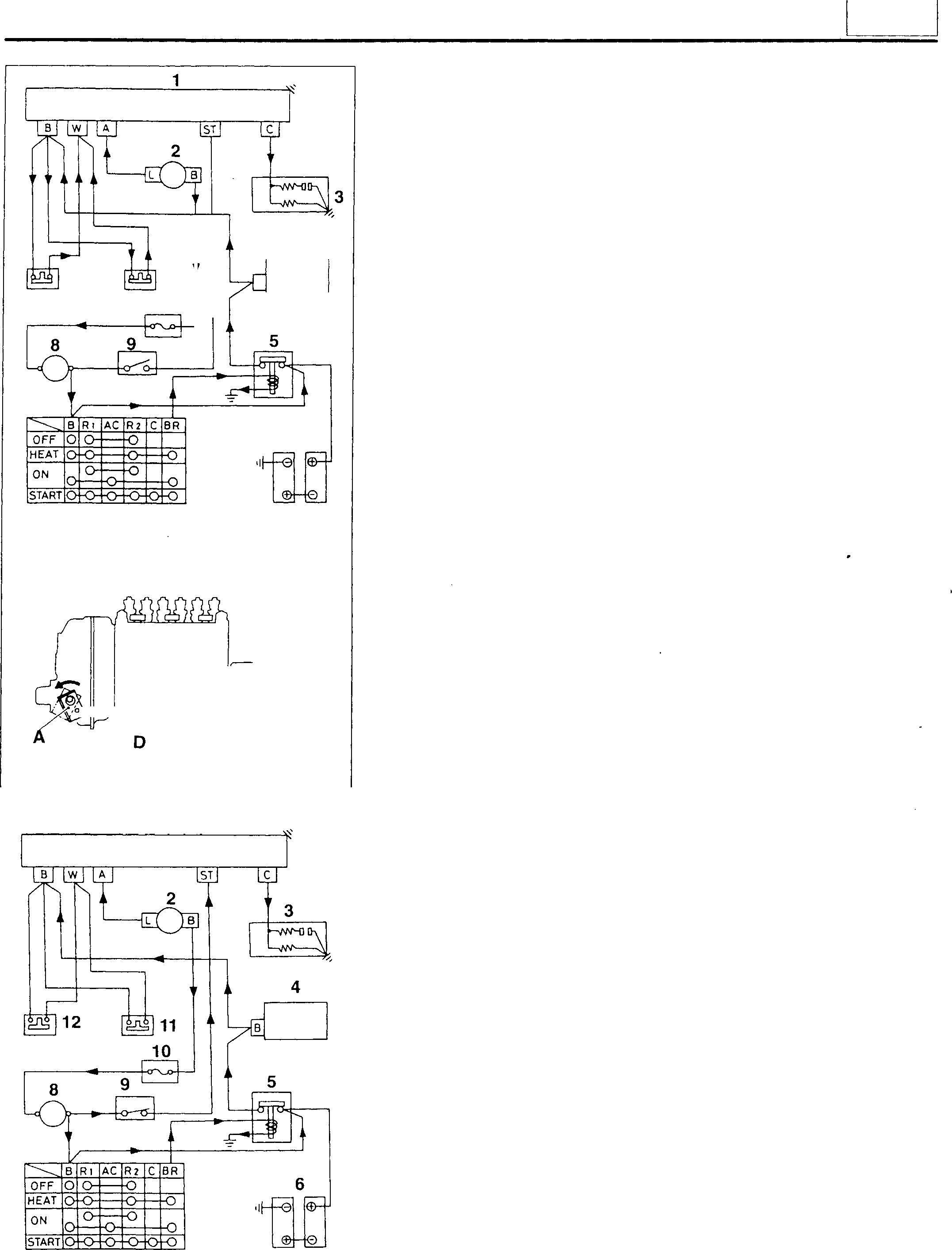
When engine is manually stopped
• Positionof stopswitch 9: ON
Irrespectiveofthegeneratingvoltage of thealternator2, currentfrom stopswitch9flowstotheinternalcircuitviaST-terminalofthesolenoid relay1 toactivatetheinternalswitchoftherelay, andthecurrentflows asfollows:
1 (8)➔ Internal switchofthe relay➔ 1 (C)➔ 3➔ Earth
• Asaresult, engineisstoppedinthesamewayas theautomatic stop.
12 7 11 10 B 4 6 18742 3 ·�-� 18743 1 7 18744 54
½
12--1
54-25
STRUCTURE AND OPERATION
Terminal B
Terminal C
Terminal H
Terminal S
• WhenthestopswitchissettoON, thecontactopens. When the switch is setto OFF, the contact closes.
• On normal condition, solenoid 2 is energized and the stop lever A of the injection pump governor is at the drive side B to keep the engine in running condition.
• Whenatroubleoccurs, currenttoactivatethesolenoidiscut offand solenoid 3 losesitspullingforce. Thenthestoplever A is pulled to the stop side C by its return spring and the engine is stopped.
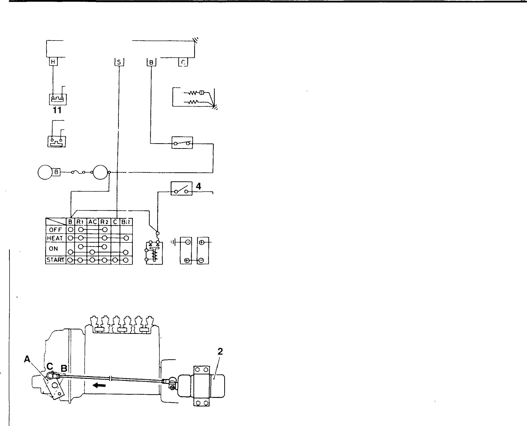
<Run-On> 1 2 3 8 10 9 7 6 5 18745 18746 54-26 1 Solenoid relay 2 Solenoid 3 Stop switch 4 Batteryswitch 5 Battery 6 Heaterrelay 7 Starter switch 8 Alternator 9 Ammeter 10 Engineoilpressureswitch 11 Coolanttemperature sensor B:
C:
H:
S:
Before engine starts Batteryswitch4: ON
5 ➔ 4 ➔ 6 ➔ 7 (B) ➔ 9 ➔ 3 ➔ 1 (B)
As the voltage is applied to terminal B of the solenoid relay 1, but is not appliedtoterminalS, thesolenoidrelayisnot energized. Therefore, current does not flow to thesolenoid relay 2 and solenoid relay 2 does not operate.
When engine starts
• Position ofstarterswitch 7: START
5 ➔ 4 ➔ 6 ➔ 7 (B) ➔ 7 (C) ➔ 1 (S) ➔ earth
• Atthispoint,internalswitchofthesolenoidrelay1 turnsonandthecurrentflows asfollows:
1 (B) -p Internal coil ofrelay ➔ Earth
4 Internal switch ofrelay ➔ 1 (C) ➔ 2 ➔ Earth
• Duetotheactivationofthesolenoid2, thestopleverAoftheinjection pumpgovernorispulledto theposition B and the enginestarts.
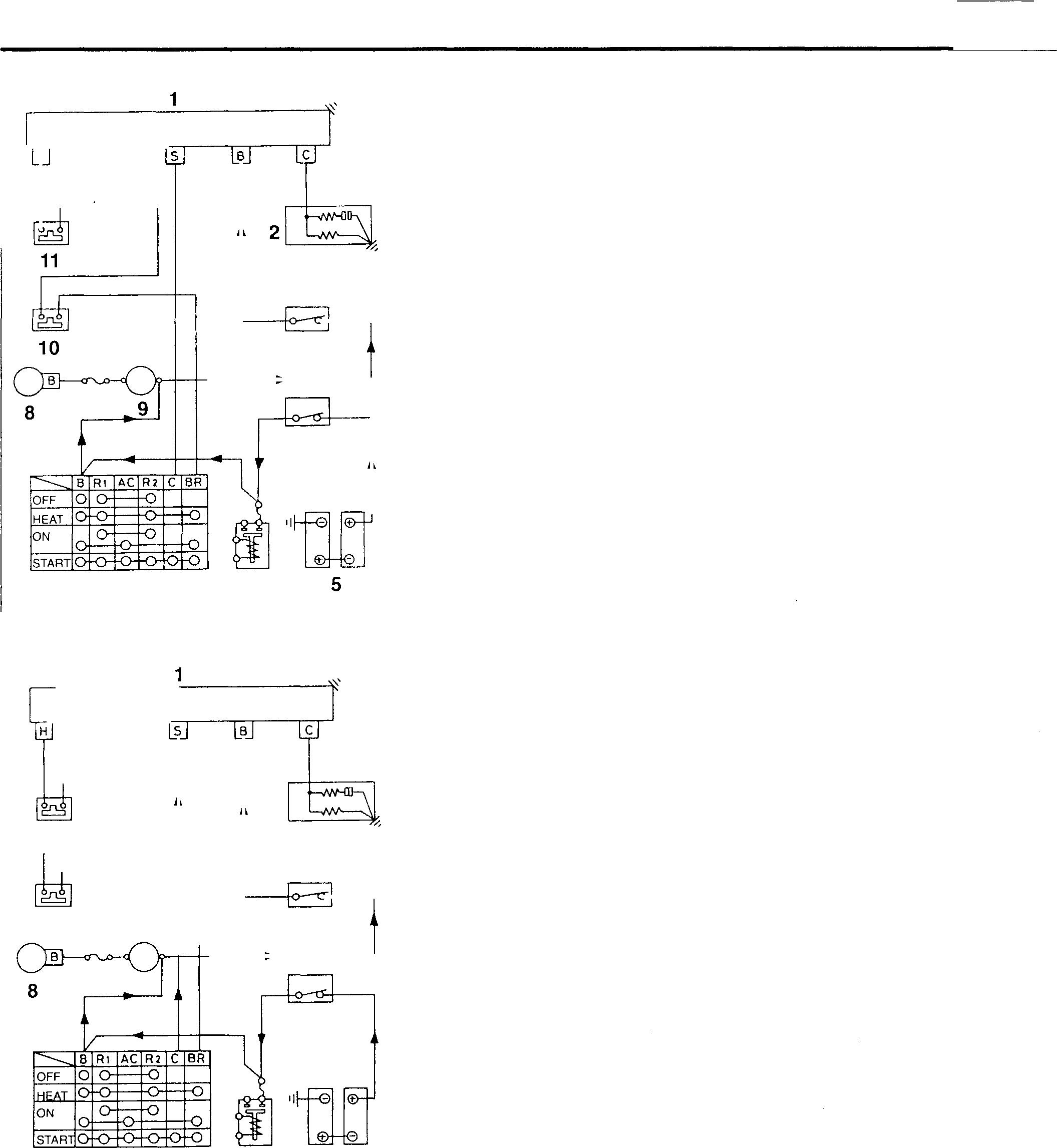
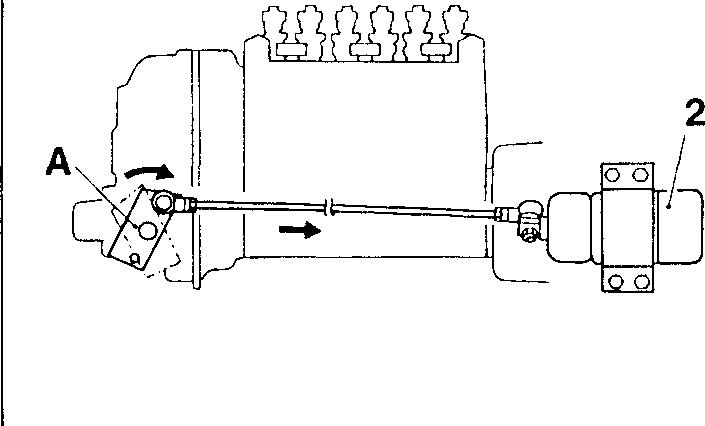
H 3 7 6 11 3 10 9 4 7 6 4 18747 2 5 18748 18749
I s4J
5../--27
STRUCTUREAND OPERATION
After engine has started
• Position of starterswitch7: ON
Thecurrentfromthestarterswitch (terminal C) tothesolenoidrelay 1 (terminal S) is cut off.
However, solenoid2remainsactivated astheinternalswitchiskeptin the ON positionby the capacitor in the relay.
• During this period, engine oil pressure increases to close the engine oilpressureswitch1O, andthecurrent flows as follows:
7 (BR)➔ 10➔ 11➔ 1 (H)➔ Internal coilof relay➔ Earth
• Inthisway, internalswitchof relay isheldON to keepthe enginerunningirrespective ofthe discontinuation ofthecurrenttotheterminal S of the solenoidrelay 1.
When engine is automatically stopped
Whentheoilpressureabnormally fallsorthecoolanttemperatureabnormally riseswhiletheengineisrunning,thecontactoftheengineoilpressure switch 10 or coolant temperature sensor (thermo switch) 11 turns OFF to stop the supply of current to the solenoid relay, so the solenoid relay stops operating. Accordingly, the solenoid 2 also stops operating, andthestopleverA ofthe governorismovedtothestoppositionby the return spring andthe engine is stopped.
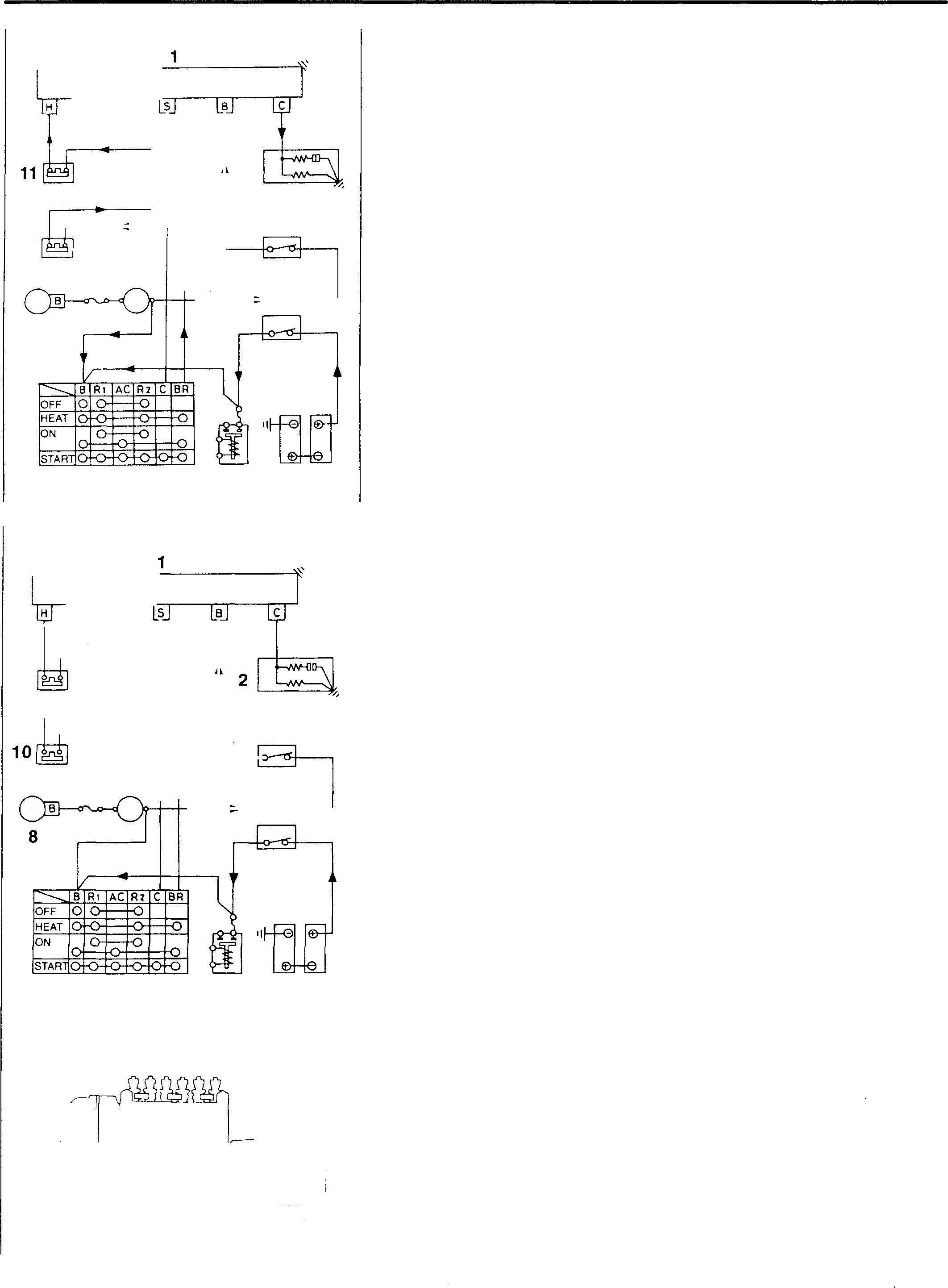
10 8 11 9 7 6 9 7 6 2 3 4 S 18750 3 4 5 18751 ( ; 1 2 A r : / / �� 18752 54-28
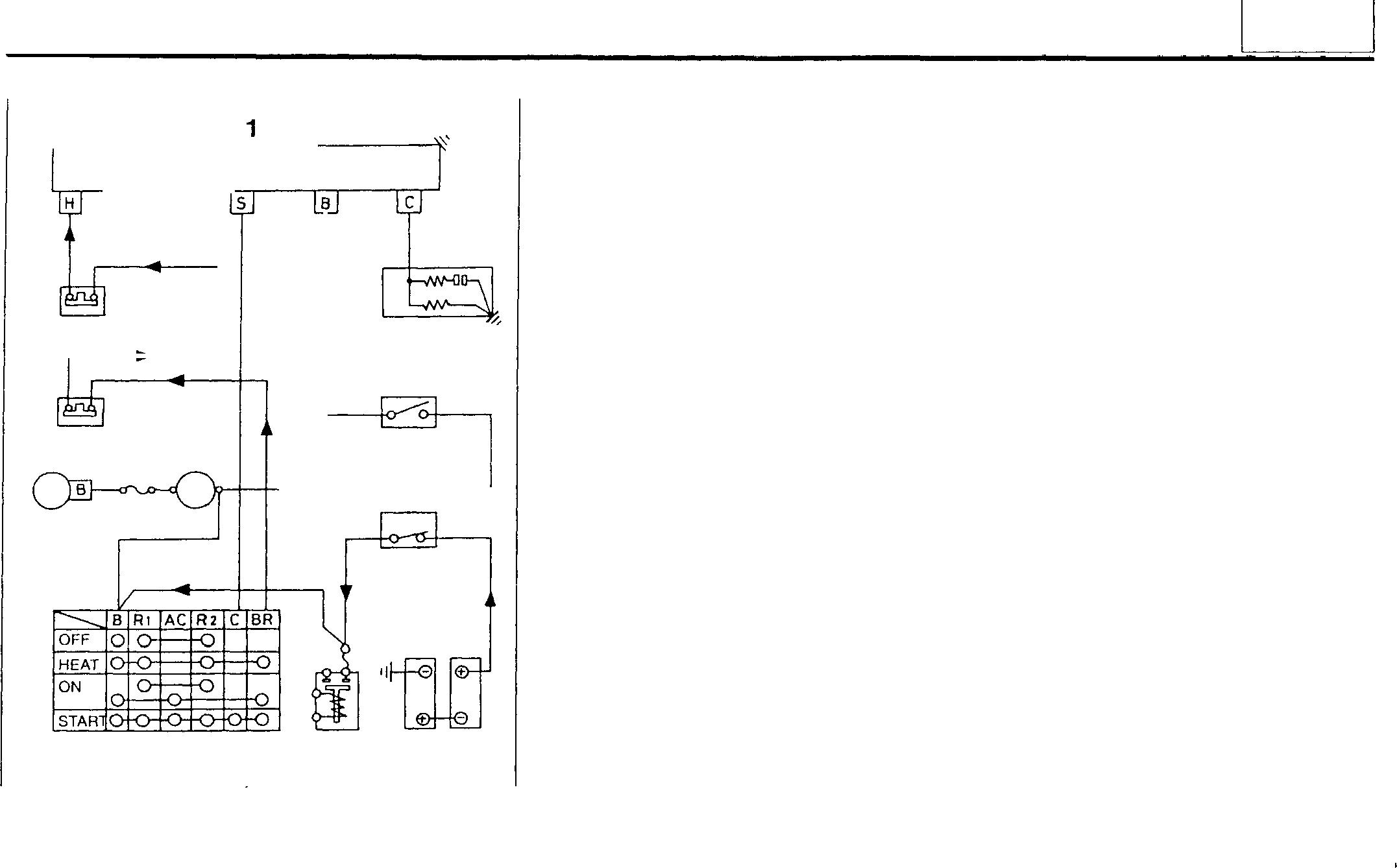
When engine is manually stopped
• Position of stop switch 3: ON (ON: Contact is opened; OFF: Contact is closed)
When the currentto the solenoidrelay 1 (terminal B) is cutoff, the currentfromthesolenoid (terminal C) tothe solenoid2isalsolost, andthe engine is stopped in the same way as the automatic stop.
11 10 8 9 7 2 6 3 4 5 18753 54
54-29
TROUBLESHOOTING
Alternator
Defective conditions Q) ,__ Ol E cu Q) ·.;:: .c 1ii El -� t:: u U) ' 0 -� Q) Q_ c .c '( E Q) CJ) .c :i::: (D ;::..al Cll c� Cll C > .D .c 0 Cll Ol :3 CJ) .Q"> CJ) C ,__ Q) .c 0 Cll .D CJ) :3 - .c ,__ Remarks Cll � .D al u Q) Q) :::J - Q) C: "O � <ii CJ).c 0 0 "O Q) - Q) E C -Q) C Q) "O Q) ·--E - Ol Q_ 0 Ol Z O CJ),__ E C a; 0 u - Cll :::J 2 -� ,__.c Q) CO 0 OU - CJ) c c c £ C C Cl)·C"O Q) Q) Q) £ u CJ) ,__ ..'.. :i::: :i::: :i::: -� Q) Q) Q) Cll Cll Cll � � 0 == > Probable causes enenen CJ)"O <( 0 Connector incorrectly connected, harnessopen-circuited, defective grounding 0 0 Blown fuse 0 0 0 Weak tension of V belt 0 0 (l]Gr14 Broken V belt 0 0 [JjGr 14 Defective battery 0 0 Alternator Stator coil open-circuited 0 Stator coil andcore short-circuited 0 Fieldcoil defective 0 Rectifier defective 0 Regulator defective 00 0 Brush worn (if brush isprovided) 0 Sagging brush spring (ifbrush is provided) 0 Defective wiring 0 54-30
Starter
Connector incorrectly connected, harness open-circuited, defective
grounding
starts but engine does not start
Starter, Preheater
54
Defective condition Starter
..c Ol C U) ·;:: -0 QJ QJ QJ E £ C iii "§ QJ ci C C QJ ..c iii QJ ..c t:: Remarks t:: QJ a. � E U) - :5 Cll Cll QJ e 0 a. en en 0 E- .0 in u .5 g U) Q) .8 0 0 QJ 0 .0 C rJ) rJ) iii t:: C 0 -0 C'- iii rJ) rJlCll QJ QJ +-'Cl) rJ) C QJ QJ QJ Eo o- QJ C 0 0 Ol 0-0 '-rJ) 0 Cll -0 Ol u:5 mo -0 u .!!1 '- c-5 c.o QJC QJ Q) QJ QJ ..c rJ) C C C t:: 0 '- 0 '- �QJ ·ci Ol Cll ·-..c ·c Cll Ol c- C C C Possible
if) a::"§ ·-QJ -0 Cl. Ol u..-c w w w
causes
0 0 0 0 0
Blown fuse 0 Insufficient capacity of battery 0 0 Starter
of magnetswitchbindingor deposited 0 Coil of magnet switch open-circuited 0 Overrunning clutch in defective operation 0 Worn or damaged pinion 0 Defective starter relay 0 Defective starter switch 0 0 Worn or damaged ringgearof flywheel 0 [lJGr11
Contact
Defective condition QJ iii QJ ..c t:: � Remarks a. QJ rJ) .0 .8 -0 C iii C u Q) QJ C C ·ci "6i C C Possible causes ww Defective heater relay or glowrelay wiring 0 0 Defective battery wiring 0 0 Defective airheater orglowplug wiring 0 0 Defective airheater or glow plug 0 0 Defective coolant temperature sensor 0 [lJGr14 Defectivecoolant temperature sensor wiring 0 54-31
ON-VEHICLE INSPECTION AND ADJUSTMENT
Inspection of Preheater System <Glow Plug Specification>
• Set the starter switch to OFF.
2 1 08718
Inspection of Safety Relay
• Connecttheinspectionlamp 2 (24V-1.8Worthereabouts) totheglow plug 1.
• Set the starter switch to the HEAT position.
• If the inspection lamp 2 does not come on, check the glow plug or heater relay.
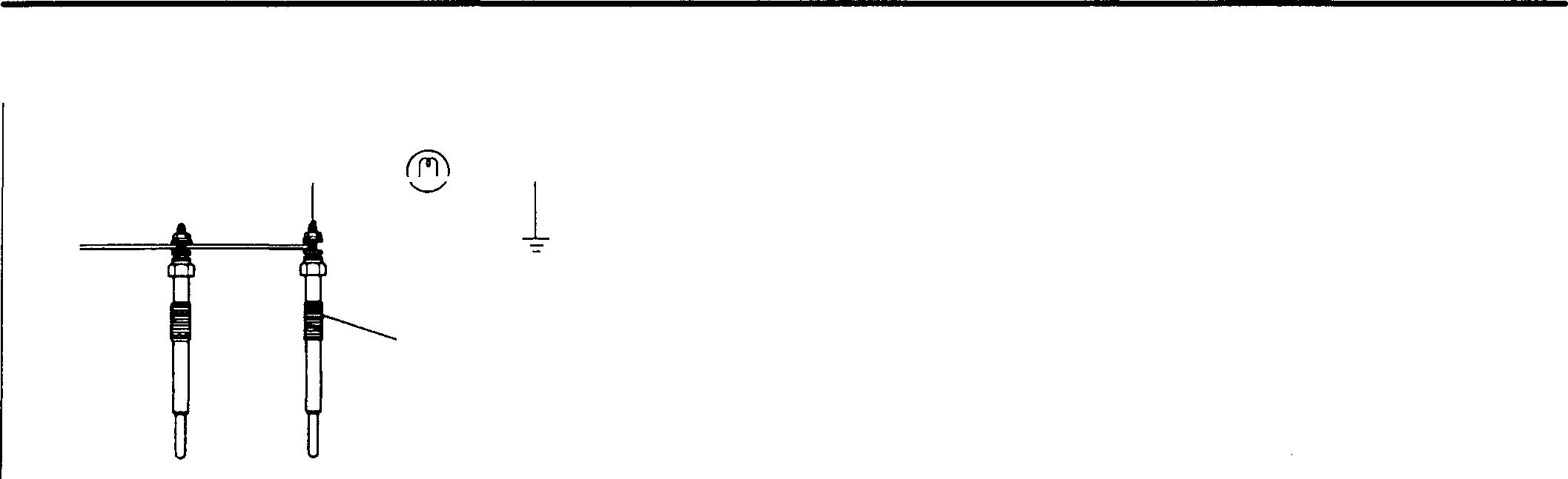
Service standards Unit: mm
Location Maintenanceitem Standard value Limit Remedy
Outputvoltage
Whenengineisstationary 1V or less - Replace alternator orwiring. atterminal P
Outputvoltage
Whileengineisrunning 12- 16V Check and replace wiring.(atidle,600 rpmor more)
Whileengineisrunning Approx.24V - Check and replace wiring. at terminal R
Outputvoltage
Whenengineisstarted 1V or less -
• Ifthe outputvoltageisclose at terminalS (incrankingstate) tothebattery voltage, 6 replace the safety relay.
• If the output voltageis0V, check and replace parts
Outputvoltage
Whileengineis running 5V or less (but not0V) -
• Replace atterminal L
• If the outputvoltage isclose tothe battery voltage, inspectthealternatorand herness and replaceifneeessary.
54-32
(1) Checkingoutputvoltageat terminal P
• Connect the voltmeter (pointer type) 7 asshown.
1 Battery
2 Batteryrelay
3 Starter switch
4 Fuse
5 Alternator
6 Safetyrelay
7 Voltmeter (pointertype)
A:Toterminal Bofstarter relay
B:To terminal Lof starter relay
E:Terminal E
L:Terminal L
P:Terminal P
A:Terminal R
S:Terminal S
• MeasurethevoltagebetweenterminalPintheillustration andtheground.
• Ifthereadingisoutofthestandardvalue, thealternator5 or wiring is defective. Check all the parts and replace defectiveones.
• Starttheengineandletitrunatidle(600rpmormore)and measure thevoltage..
• If the reading is 0V, the wiring to terminal P is short-circuited. Check the wiring and connector connections. Replaceifdefective.
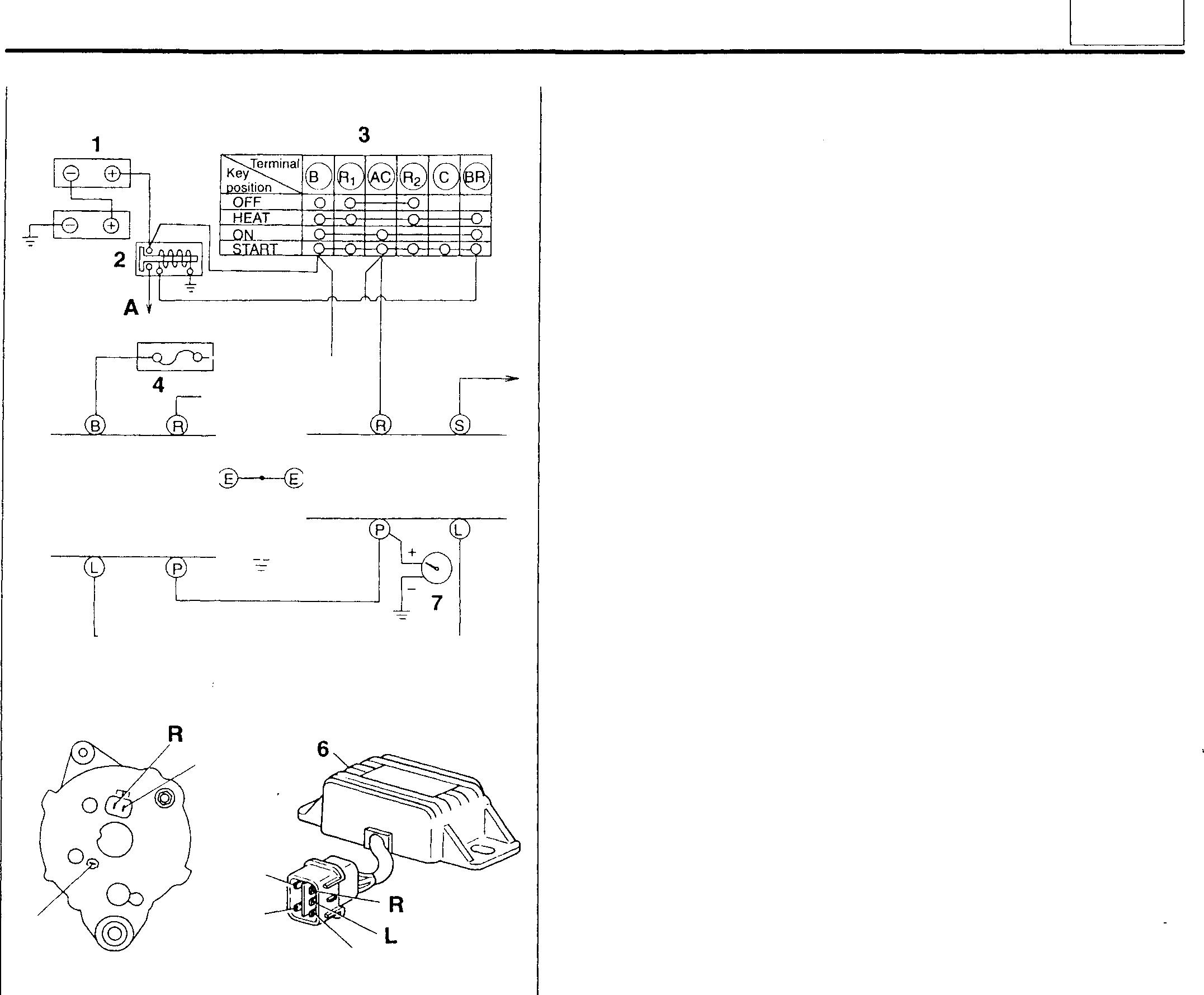
Mitsubishi 6D16TLEA engine parts contact: email: engineparts2@gmail.com
Phone: 269 673 1638
Text: 269 760 8652
B 5 6 18469 L 5 p p E s 17534 17535 54
54-33
ON-VEHICLE INSPECTION AND ADJUSTMENT
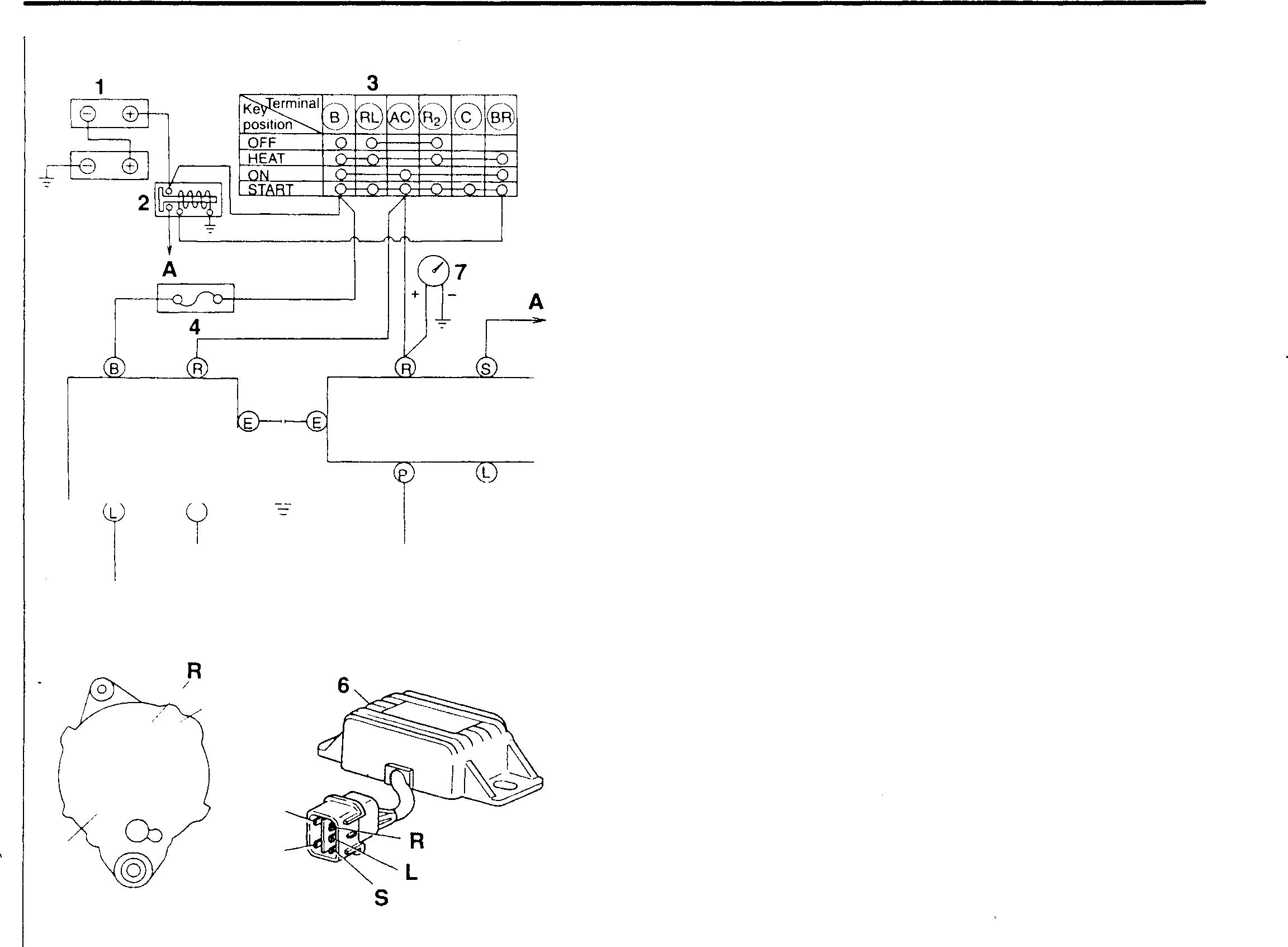
(2) Checking output voltage atterminal R
• Connect thevoltmeter 7 as shown.
• Placethestarterswitch 3 intheON positionandmeasure the voltage.
• When the reading is out of the standard value, checkthe wiring. Replace ifdefective.
5 p / ,L o�@ o'z)o 5 / p
54-34 6
p E
17534
18471
17535
(3) Checking output voltage at terminal S
• Connect the voltmeter 7 and lamp 8 as shown.
• Set the starter switch 3 to the START position and measure the voltage between the safety relay 6 (terminal S) and the earth in the cranking state.
• If the reading is out of the standard value, the following points are likely to be defective. Check all the points and replace if defective.
• When the reading is close to the battery voltage, the safety relay 6 is defective.
• Whenthereadingis0V, thefollowingproblemsaresuspected.
Defective wiring
Incorrectly connected connector
Defective starter relay
Defective starter switch
• Start the engine and let it run at idle (600 rpm or more).
• Measure the voltage at terminal P.
• Ifthereadingisoutofthestandardvalue, replacethealternator 5.
• Intheidlingstate, checktoensurethatthelamp8doesnot come on. When the voltage at terminal P is normal and the lamp comes on, replace the safety relay 6.
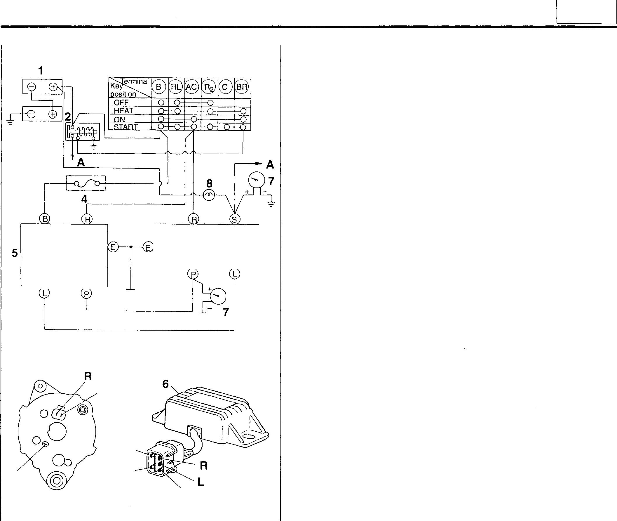
3 -= -=L 5 p p E s 17534 6 18470 17535 54
54-35
ON-VEHICLE INSPECTION AND ADJUSTMENT
(4) Checking output voltage at terminal L (where no charge lamp is provided)
• Connectthevoltmeter7asshown.
• Placethestarterswitch 3 attheONpositionandmeasure the voltage.
• If the reading is out of the standard value, replace the safetyrelay 6. If the reading is close to the battery voltage, check the alternator 5 and wiring, andreplaceifdefective.
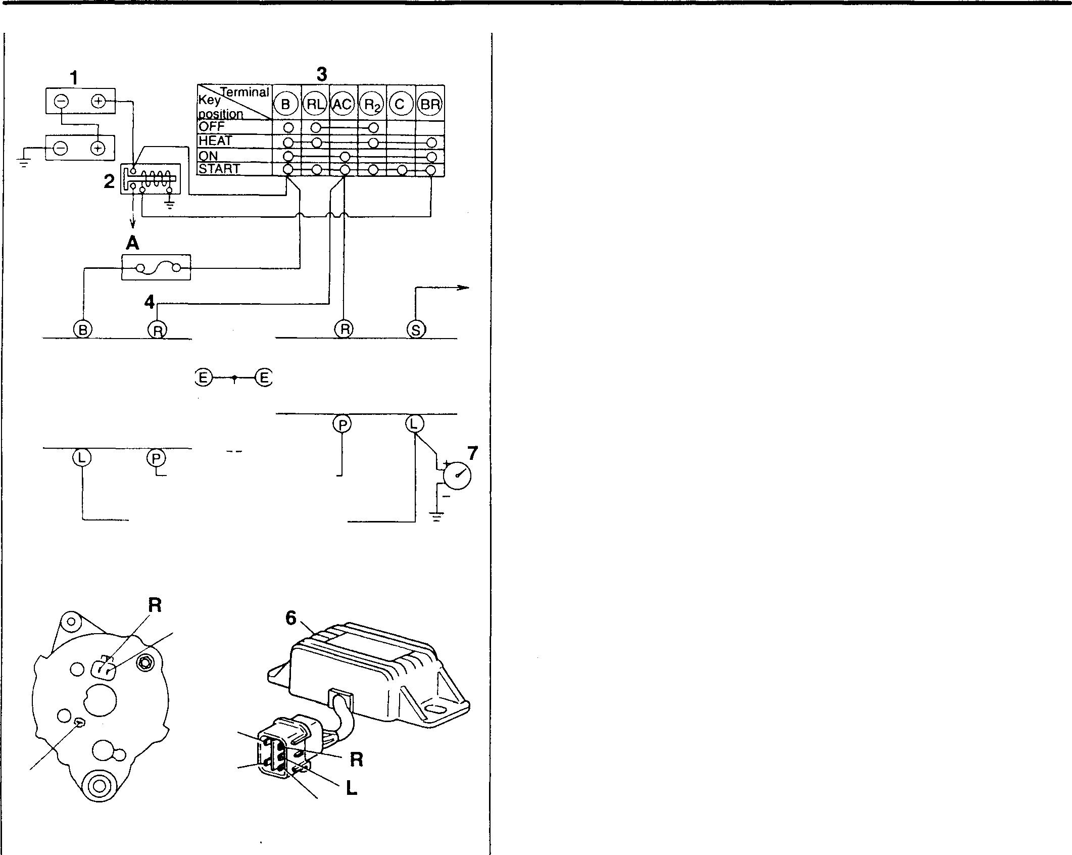
5 = L 5 p p E
54-36 A 6
17534
s
18472
17535
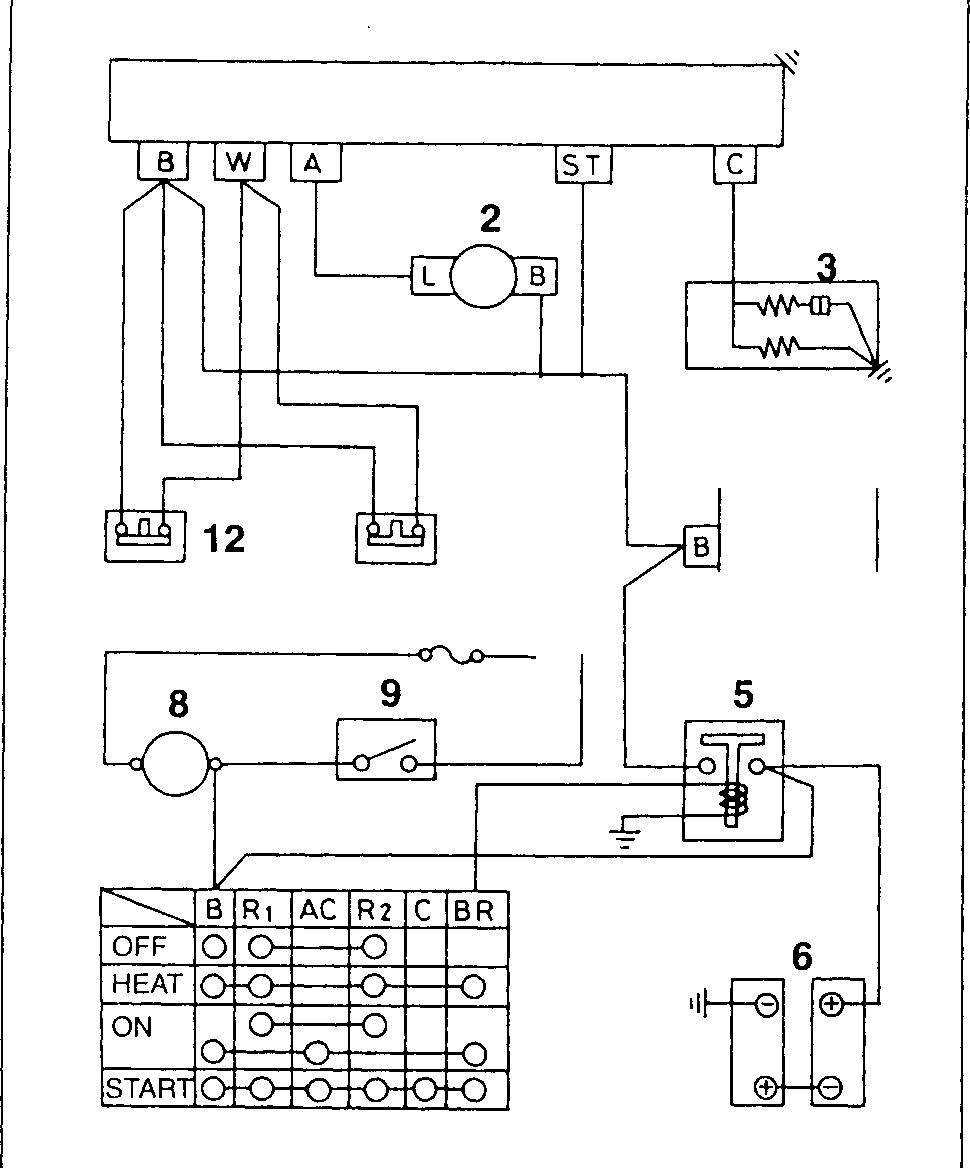
Measure the voltages at the terminals of thesolenoid relay 1. Performchecks as described below and replace defective parts.
When starter switch 7 is placed at ON position, solenoid 3 operates.

Measure voltage at terminalA. (24V available?) No
Measure voltage at terminalST.


Automatic Stop System <Shutdown> 7 1 11 10 4 18737 1 Solenoid relay 2 Alternator 3 Solenoid 4 Starter 5 Batteryrelay 6 Battery 7 Starterswitch 8 Ammeter 9 Stopswitch 10 Fusebox 11 Engineoilpressureswitch 12 Watertemperaturesensor 54
Yes I,________ Alternator2 defective 24V >-- ---I Stopswitch 9 defective ov__..l Solenoid
1 defective 54-37 Mitsubishi 6D16TLEA engine parts contact: email: engineparts2@gmail.com Phone: 269 673 1638 Text: 269
8652
relay
760
ON-VEHICLE INSPECTION AND ADJUSTMENT
Even when stop switch 9 is set to ON, engine does not stop.

Measure voltage at terminal ST. �-�...I Stop switch 9 defective
24V
Measure voltage at terminalC. ov >-----------1 Solenoid relay 1 defective
24V I �- ----► Solenoid3 defective
Whenoilpressureisabnormallylowor coolant temperature abnormally high, enginedoes not stop.
Measure voltage at terminal W.*
24V
Measure voltage at terminal A. (28 to 29V available)*
Yes

ov * Measure while engine is running. Engine oil pressure switch 11 or water temperature sensor 12 defective
�-�-1 Alternator2 defective
Measure voltage at terminal C.* ov ----1 Solenoidrelay 1 defective
24V I �- - --► Solenoid 3 defective
Afterenginehasstopped, solenoid 3 is not caused to be OFF.
Measure voltage at terminal C.
24V
Measure voltage at terminal ST. Yes
Measure voltage at terminal A. (24V available?) .,____ov__, Solenoid 3 defective
24V �------- Stop switch 9 defective
No _I Solenoid relay 1 defective
Yes
I - • Alternator2 defective
54-3R
While engine is running, solenoid 3 is operated andenginestops.
Measurevoltage at terminal C.*
24V
Measurevoltageat terminal ST.* ov
* Measure whileengineisrunning.
Measurevoltageat terminal W.* -,__o_v _, Solenoid3 defective

24V I'>------ Stopswitch 9 defective av �---- --� -��--...I Solenoidrelay1 defective
24V Engine oil pressure switch 11 or water temperature sensor 12 defective i Ifinorder
Oil pressure or coolant ternperatureabnormal
54 54-39
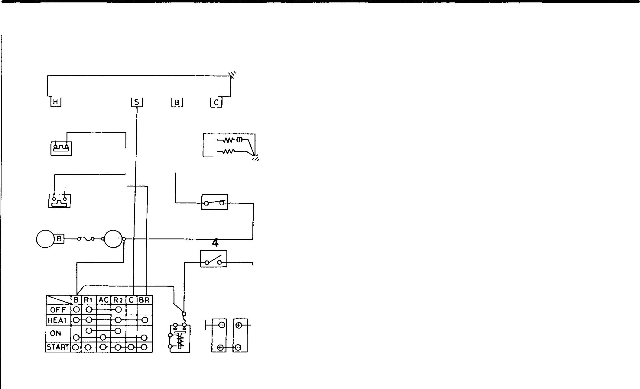
Measure the voltages at the terminals ofthe solenoid relay 1. Performchecks as describedbelow and replacedefective parts.
Whenthebatteryswitch4issettoON, thesolenoid2isoperated. Orwhenthe starterswitch 7 issettotheONposition withthebatteryswitchatON, thesolenoid isoperated.

Measure voltageat terminal S.
relay1 defective
INSPECTION AND ADJUSTMENT <Run-On> 1 Solenoid relay 2 Solenoid 1 3 Stopswitch 4 Battery switch 5 Battery 6 Heater relay 7 Starterswitch 2 8 Alternator 9 Ammeter 11 10 Oil pressureswitch 3 11 Water temperature sensor 10 9 8 ,1 7 6 5 18745
ON-VEHICLE
54-40
OV >------I
24V
engine parts contact: email: engineparts2@gmail.com
269 673 1638
269 760 8652
Solenoid
�- ---1►, Starter switch 7 defective or incorrectwiring Mitsubishi 6D16TLEA
Phone:
Text:
Evenwhenstarterswitch7issettoON position,solenoid 2 doesnotoperate. (Batteryswitch4:ON)
Checkbattery. Good
Measurevoltageat terminalB 24V
Placestarterswitch7at
STARTpositionandmeasure voltageatterminalS. (18Vormoreavailable?)
Yes
Defective I -,._____Battery5defective OV , No_Battery5defective(Capacityinsufficientwhenloadsareplaced)
MeasurevoltageatterminalC.)-No_,Solenoidrelay1defective (Battery voltage avaHable) I L_ ___ Yes•ISolenoid 2 defective
Istherecontinuitybetween terminalsofstopswitch3? '-- No___IStopswitch3defective Yes I .__ lncorrectwiring ______�
Whenstarterswitch7isreturnedfrom STARTpositiontoONposition,solenoid 2 operates.

Placestarterswitch 7 at
STARTpositionandmeasure voltageatterminalS. (18Vormoreavailable?) Yes I ,___Solenoidrelay1defective
___N_o __.l Battery 5 defective
54 54-41
ON-VEHICLE INSPECTION AND ADJUSTMENT
When oil pressureisabnormally lowor coolant temperature abnormally high, engine does not stop.
Measure voltage at terminal H.*
OV
Measurevoltageat terminal S.*
OV
Measure voltage at terminal C.*
24V
* Measure while engine is running.
�
Engine oil pressure switch 1O or water temperature sensor 11 defective
24V I >----� Starter switch 7 defective
24V I>------- Solenoid 2 defective
ov ___l Solenoid relay 1 defective
Even when stop switch 3 isset to OFF, engine does not stop.
Measure voltage at terminal B.
�
24V I>----- Stop switch 3 defective
ov __l Solenoid 2 defective
While engine is running, solenoid 2 is operated, and engine stops.
Measure voltage at terminal C.*
ov
Measurevoltageat terminal B.*
24V
Measure voltage at terminal H.*
* Measure while engine is running.
24V I ,,__ __ Solenoid 2 defective '>--
ov __l Stop switch 3 defective
24V I ,__ __ Solenoid relay 1 defective OV �--- -
Engine oil pressure switch 10 or water temperature sensor 11 defective If inorder
Oil pressure or coolant temperature abnormal
54-42
54 MEMO 54-43
ALTERNATOR <24V-35A>
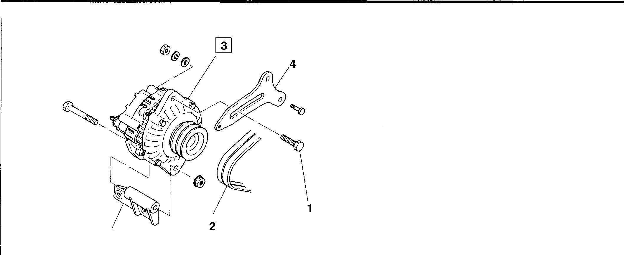
*
• Removal sequence
1 Adjustbolt
2 V belt
3 Alternator assembly m P.54-46
4 Adjust plate
*: Alternator bracket
WARNING,&--------------------------
Beforeremovingthealternator3,besuretodisconnectthenegativeeterminalofthebatteryandinsulateitwith atapeorsomethingelse. Ifthenegativee terminalisnotdisconnected, thebatteryvoltageisalwaysavailable at terminal B and is dangerous.
• Installation sequence
Reverse the order of removal.
• Adjustmentafterinstallation
Adjust the tension of the V-belt 2. ffi Gr 14
Servicestandards
Location Maintenance item
3 Alternatoroutput current (* When hot, when 27Vis generated)
Regulatorregulated voltage (5000rpm, loads5Aor less)
- Replace
*:"Whenhot"referstothestateoftheengineafter30minutesofmaximumoutputoperationat5000rpmatanormalambienttemperature.
16745
Standard value Limit Remedy 1500rpm 20Aor more - Check 2500rpm 29Aor more5000rpm 33Aor more28.5±0.5V
54-44
♦ Service procedure
@] Inspection of alternator
(1) Inspection of performance of alternator (Inspection by test bench)
• Wire the alternator 3 as shown.
A: Ammeter
B: Alternator terminal B
C: Switch
D: Switch
E: Alternator terminal E
F: Load resistance (variable resistance)
G: Alternator drive motor
R: Alternator terminal R
V: Voltmeter
• Increase the load resistance F to a maximum {where practically no load current flows).
• Set the switch C and switch D to ON.
• Let the alternator 3 warm up at 5000 rpm for 30 minutes.
• Adjusttheloadresistance Fsothatthecurrentwillhavethenominal value.
Nominal value of alternator current j 24V-35A f
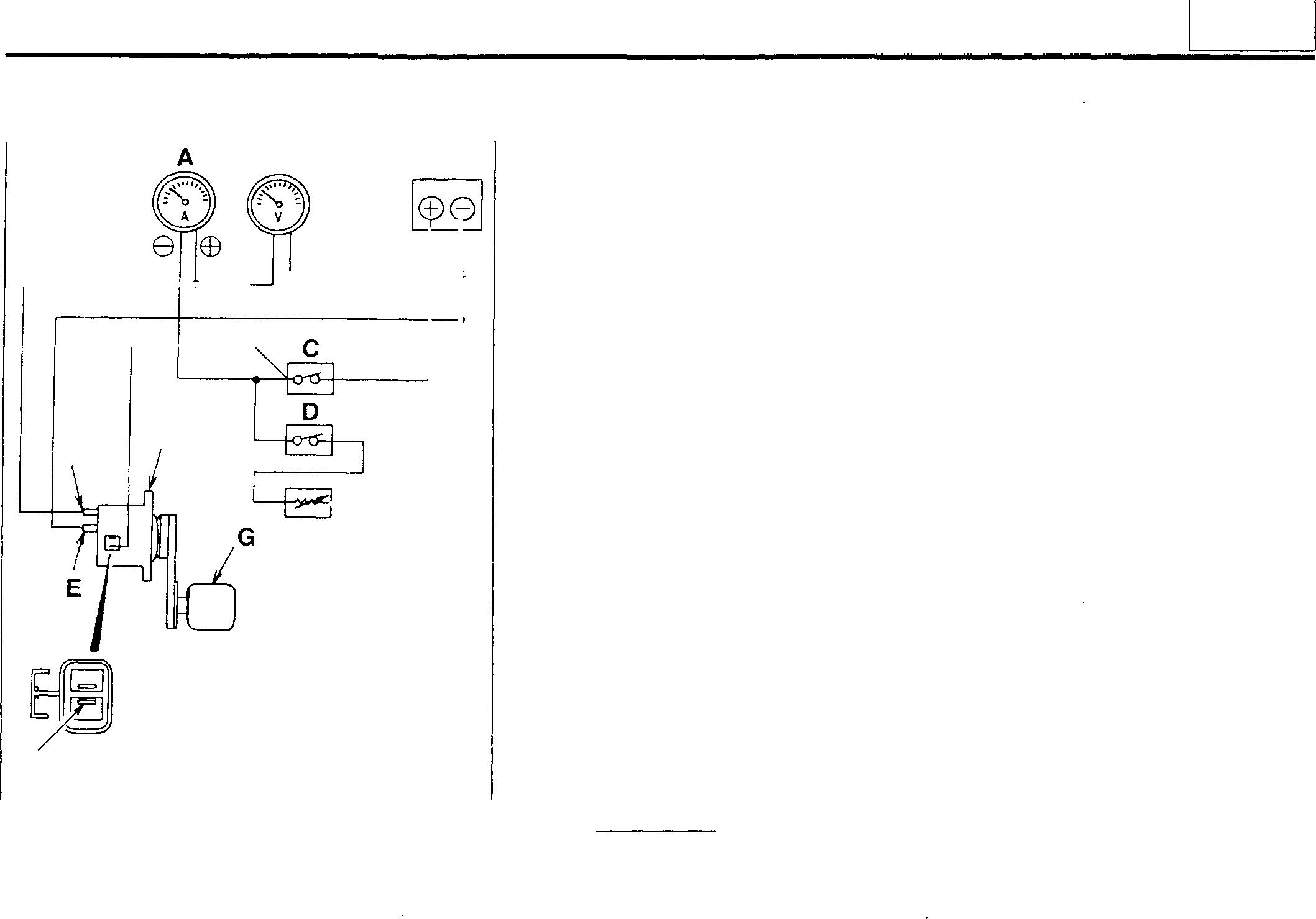
• Measure the current with the alternator 3 at each of the specified speeds.
• If the reading is out of the standard value, disassemble and check the alternator 3. Ql P.54-46
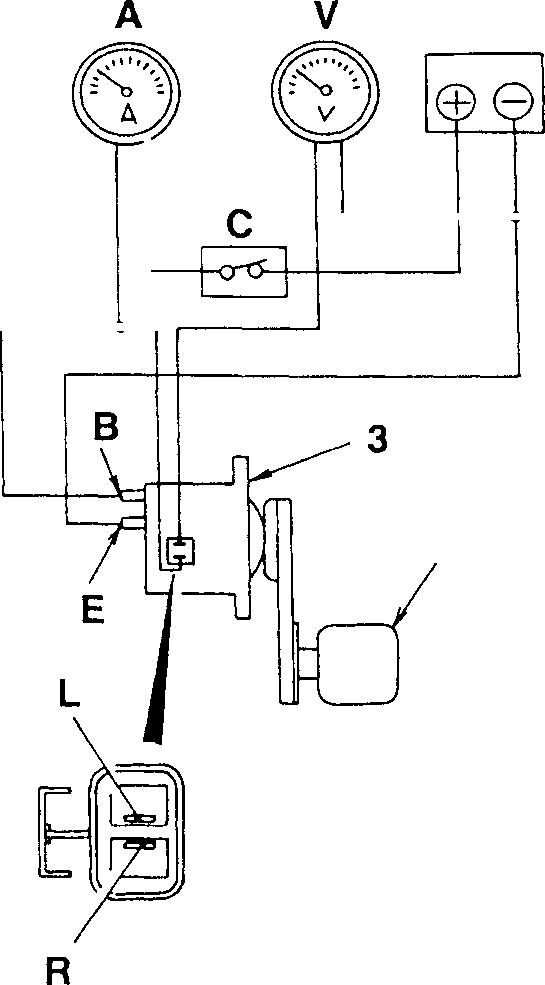
(2) Inspection of performance of regulator {Inspection by test bench)
• Wire the alternator 3 as shown.
A: Ammeter
B: Alternator terminal B
C: Switch
E: Alternator terminal E
G: Alternator drive motor
L: Alternator terminal L
R: Alternator terminal R
V : Voltmeter
• Set the switch C to ON.
• Let the alternator 3 rotate at a low speed.
• Increasetherotatingspeedofthealternator3to5000rpmandmeasure the voltage (regulated voltage). At the same time, check to ensure that the current value is SA or less.
• Ifthereadings are outof the standard values, proceed as described below.
• Ifthereadings exceedthe standardvalues, replacethe regulator {built in the alternator 3).
• Ifthereadings are below the standardvalues, checkall the parts of the alternator before replacing the regulator.
V DC24V B 3 F R 16132 DC24V 0 EB G 16133
54
54-45
ALTERNATOR <24V-35A>
AlternatorAssembly
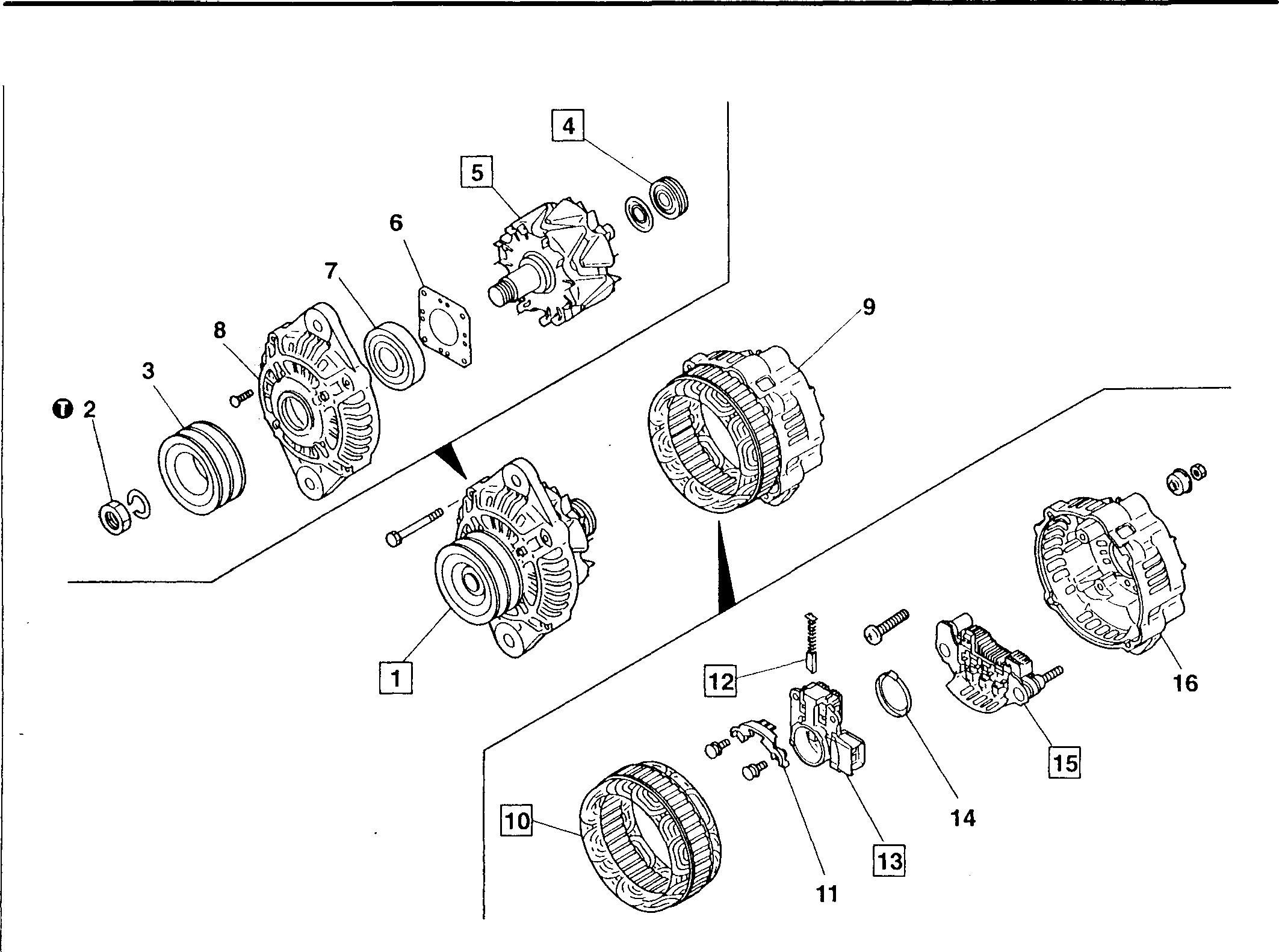
NOTE
Donotremoveparts4,7,10and12unlesstheyarefoundtobedefective.
•Reassemblysequence

9: 14➔13➔12➔11, _ I 15_____r16➔10 1:
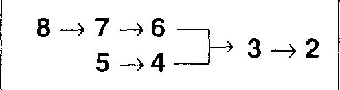
16197 •Disassembly sequence 1 Rotorandfrontbracketassembly 7 Front bearing 12 Brush 2 Nut 8 Front bracket 13 Regulator andbrush holder 3 Pulley 9 Statorandrearbracketassembly 14 Slinger 4 Rear bearing 10 Stator assembly 15 Rectifier 5 Rotor assembly 11 Cover 16 Rear bracket 6 Cover
54-46
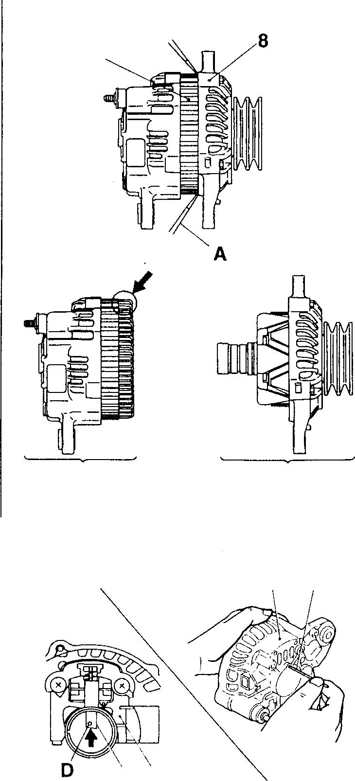
♦ Service procedure IT]
• Insert a plain screwdriver A between the front bracket 8 and stator assembly 10.
• While wrenching the plain screwdriver A, remove the rotor & front bracket assembly 1 from the stator & rear bracket assembly 9.
CAUTION_&-------------
lf the plain screwdriver A is inserted toofar, thecoil Bof the stator assembly 10 might be damaged and short-circuited.
[Installation]
Ifthebrush 12isprotrudingfromtheregulator&brushholder 13, therotor assembly 5 cannot be mounted on the rear bracket 16. Therefore, perform the followingsteps.
• Push the brush 12 into the regulator & brush holder 13.
• Insertthepin C from therearof the rear bracket 16andpress the pin C againstthe pinhole D tohold the brush 12.
Ifthebrush12iswornandthepinhole D gone,holdtheendofthebrush 12 with the pin C.
• After installation, slowly remove the pin C.
54 Service standards Unit: mm Location Maintenanceitem Standardvalue Limit Remedy 5 Rotorassembly Fieldcoil resistance (at 20°C) 9 to10.5n - Replace Slip ringoutsidediameter 33 32.4 12 Brushlength
Tightening torques Location Parts to betightened 2 Nut (tomountpulley) 10 B 9 1 16198 16 C 12 13 16199 21.5 Tighteningtorque 132 to162 {13.5 to16.5}
0
Rotor
assembly [Removal] 8 Replace Unit: N ·m {kgf·m} Remarks -
& front bracket
54-47
[Disassembly]
CAUTION_&--------------
When the rotor assembly 5 is held in a vice, make sure that the base E of the lugs of the core is held.
If the lugs F of the core are held, they will be broken or damaged.
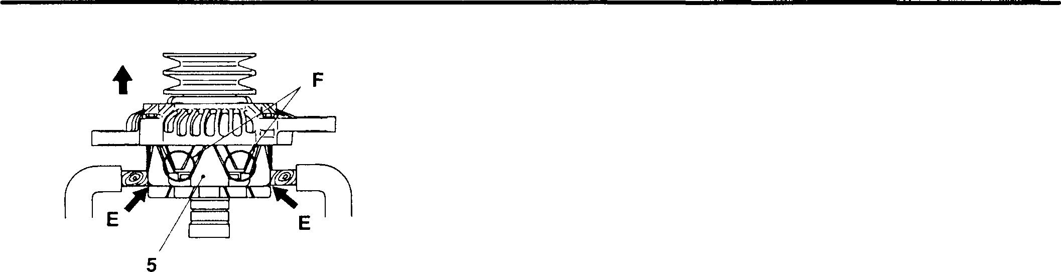
A
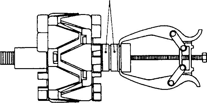
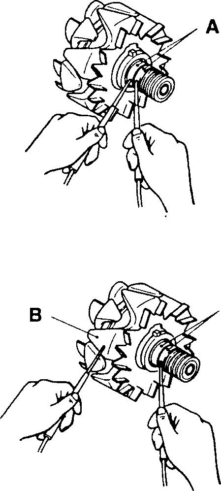
A
[i] Removal of rear bearing
CAUTION_&--------------
When the bearing puller is installed, use care to prevent damage to the slip ring A.
If the slip ring is damaged, the brush will fail to make good contact.
[]] Inspection of rotor assembly
(1) Resistance of field coil
• Measure the resistance across the slip ring A.
• Ifthereadingisoutofthestandardvalue,replacetherotorassembly 5.
(2) Continuity between slip ring and core
• Check to ensure that there is no continuity between slip ring A and core B.
• If there is continuity, it means a short circuit. Therefore, replace the rotor assembly 5.
(3) Outside diameter of slip ring
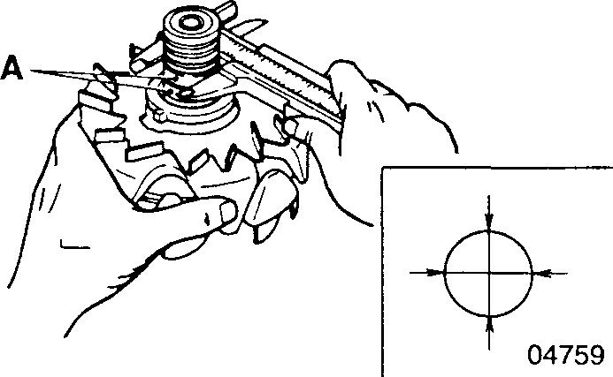
• If the outside diameter of the slip ring A is below the limit, replace the rotor assembly 5.
• If the outside diameter of the slip ring A is rough or unevenly worn, correct by grinding with emery paper or a lathe.
CAUTION_&-------------
Do corrective grinding withintheextentthattheoutsidediameter of the slip ring A does not exceed the limit.
<24V-35A>
ALTERNATOR
16223
16224
04757
54-48
04758
[IQ] Statorassembly
[Removal]
•Disconnect the leadsA and remove the stator assembly 10 from the rectifier 15.
The leads are soldered to the diode leads B of the rectifier. (Three places <35A>, four places <40A>)
CAUTION&-------------
De-solderingshouldbedonequickly(inabout5secondsorless). Thediodeswillbedamagedifheatedforalongertime.
• For installation, reverse the order of removal.
[Inspection]
(1) Continuitybetweenleads
• Check to ensure that there is continuity between each lead.
• If there is no continuity, the leads are open-circuited. Replace the stator assembly 10.
(2) Continuitybetweeneachleadandcore
• Check to ensure that there is no continuity between each lead and the core.
• If there is continuity, it means a short circuit. Replace the stator assembly 10.
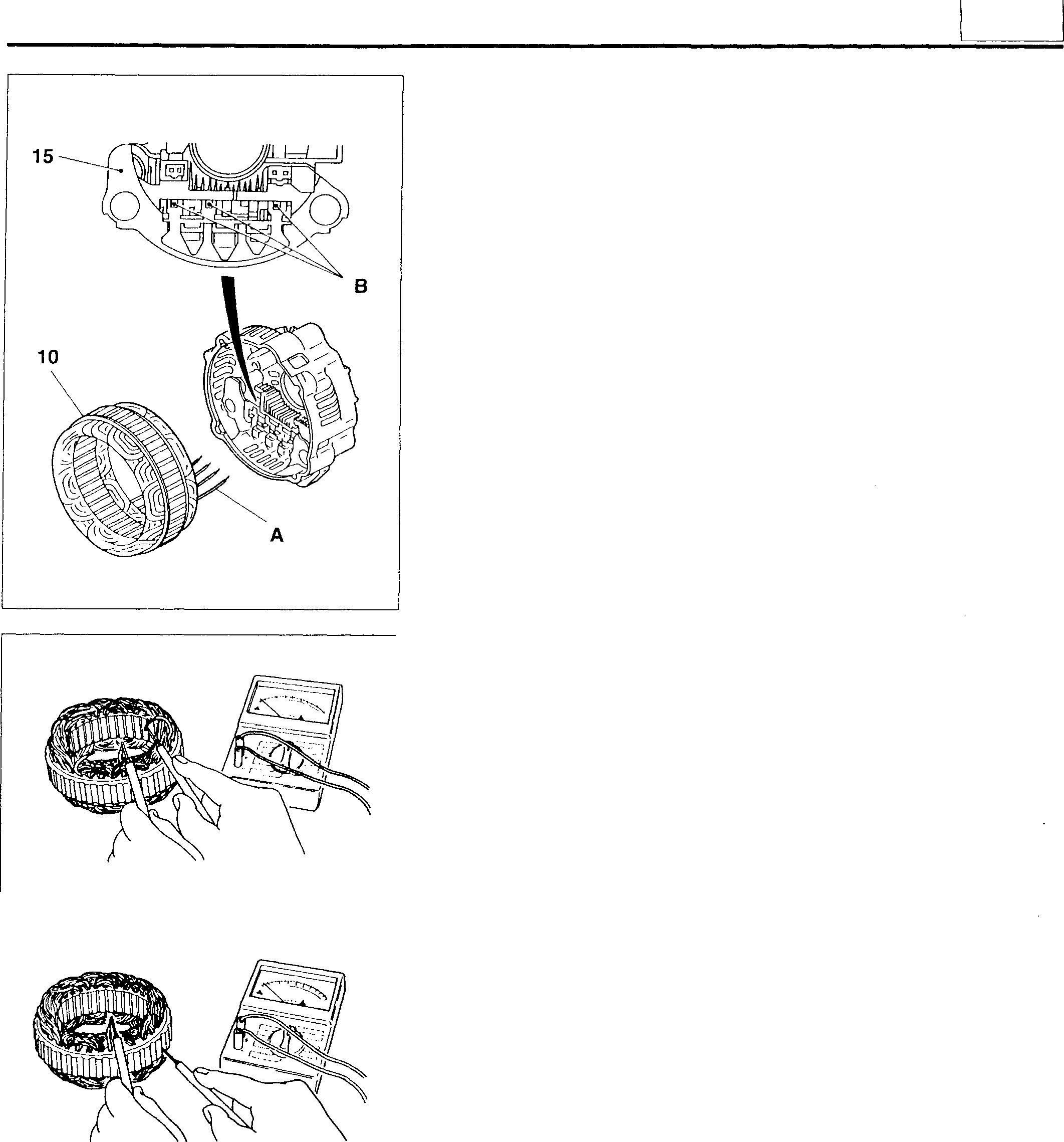
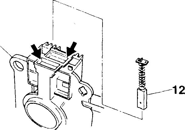
� Brush
[Removal]
After removing the cover A, de-solder the leads of the brush 12 and remove the brush from the regulator & brush holder 13.
16746 02336 02337 �A 13 16225
54
54-49
[Installation]
• Installthe brush 12 in the regulator & brush holder 13 in the direction shown.
• After installation, solder the leads of the brush 12 to the regulator & brush holder 13. Thereafter, fitthe cover A as before.
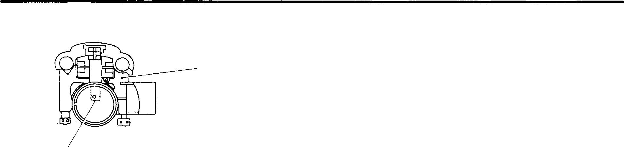
[Inspection]
If the length of the brush 12 is near the wear limit B, replace.
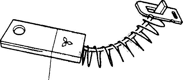
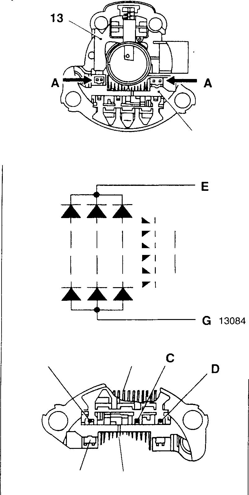
� Removal ofregulator & brush holder
• Removetheregulator& brushholder 13 by de-solderingthetwoillustratedpoints A.
• For installation, reverse the order ofremoval.
[Th] Inspection ofrectifier
• Check the rectifier 15 to see if the internal diodesfunctionproperly.
Resistance infinite in bothcases Open Resistanceclose to Q in bothcases...Short
A, B, C, D: Leads ofstatorcoilconnected E, G: Heat sinkportion F: Regulator connected
• ExchangetheEB and8sidesofthetesterandperformchecksinboth cases.
CAUTION,&--------------
When a testeris used for thechecks, the currentthat flows out from the tester is feebler than the current that normally flows throughtherectifier15,sothetestermayindicateaquestionable resistance value. In a low range, this tendency will be stronger. Therefore, it is advisable to use the highest possible range.
13 12 16231 B 04786 15 16232 A -----+--+---191----, C --+-------+---�---- F D ---+-t---.---191--___J A G F E 54-50 16233
ALTERNATOR <24V-35A>
54 MEMO 54-51 Pages
are deleted as they are not in use.
54-52 to54-93
STARTER <24V-5kW>
2
• Removal sequence
1 Earthstrap
2 Starter relay
3 Battery cable EB
4 Starter assemblyOJ P.54-96
8:Terminal B
S: Terminal S
WARNING&_-----------
Before removing the starter 4, be sure to disconnect the negative e terminal of the battery and insulate it with a tape or something else. If the negative e terminal is not disconnected, the battery voltage is always available at terminal 8 and is dangerous.
• Installation sequence
Reverse theorder ofremoval.
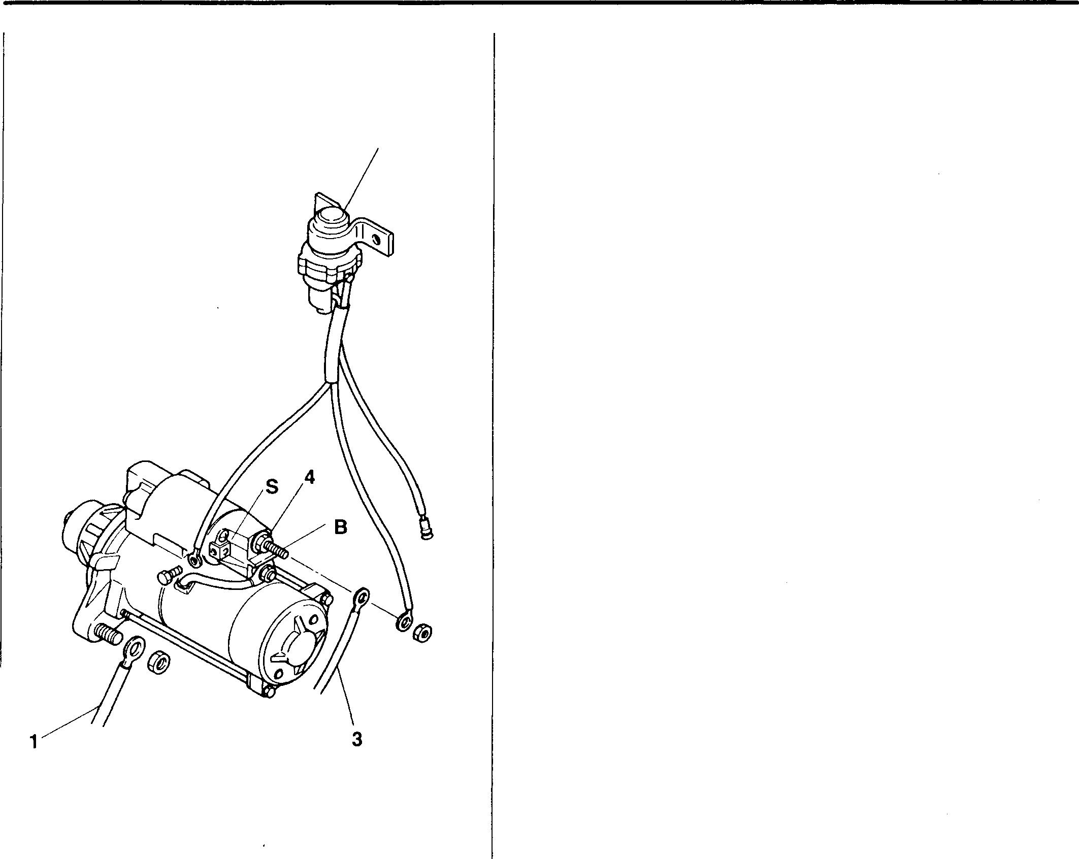
Mitsubishi 6D16TLEA engine parts contact: email: engineparts2@gmail.com
Phone: 269 673 1638
Text: 269 760 8652
54-94
16759
I s4 I
54-95
MEMO
STARTER <24V-5kW>
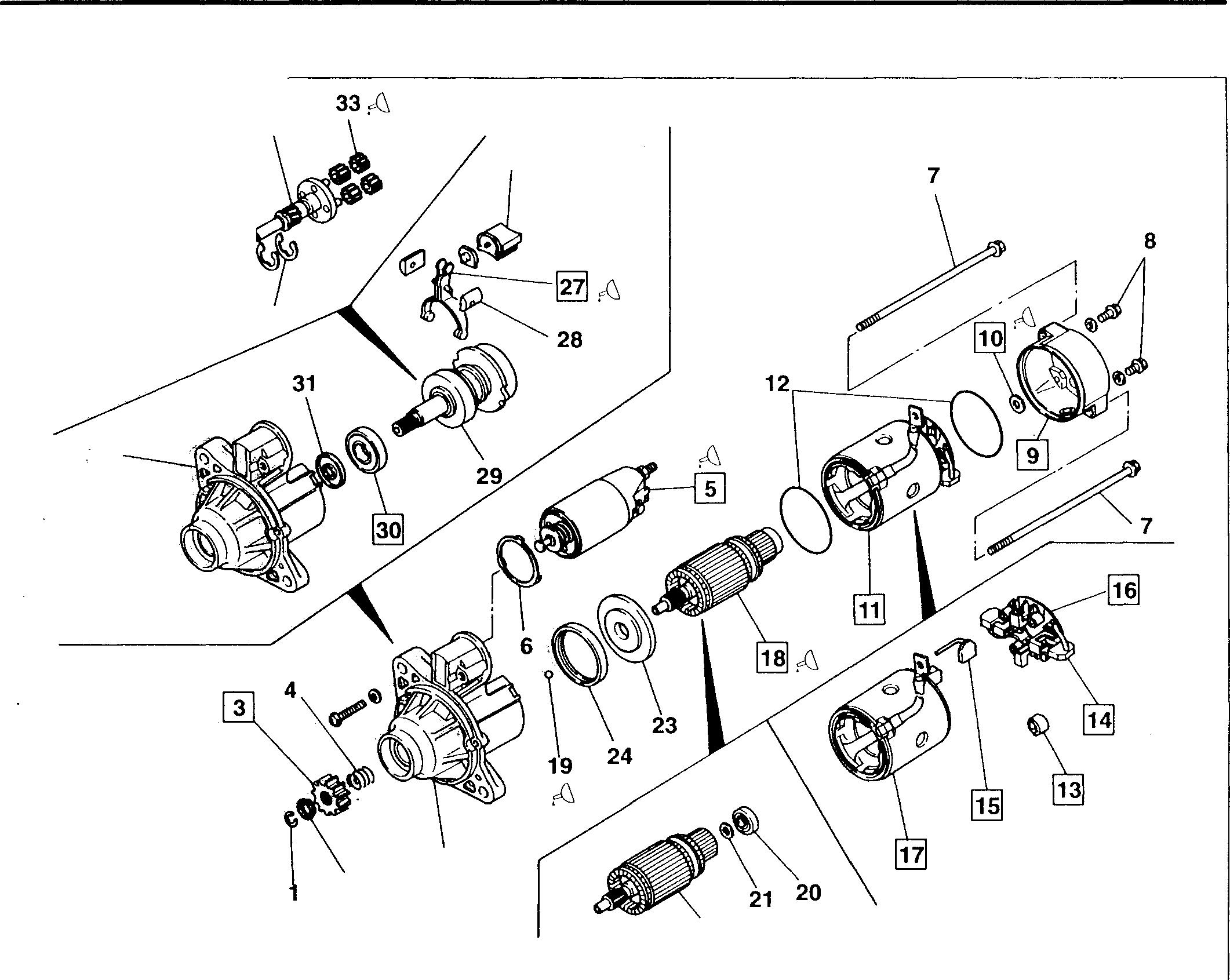
�34
Starter Assembly � 35 � 36
32 •Disassembly sequence 1 Stopper ring 2 Pinion stopper 3 Pinion 4 Spring 5 Magnet switch 6 Shim 7 Bolt 8 Screw 9 Rear bracket 10 Conical washer 2 11 Yoke & brush holder assembly 12 Rubber packing 13 Brush spring 54-96 26 25 22 14 Brush 0 15 Brush EB 16 Brushholderassembly 17 Yoke assembly 18 Armature assembly 19 Ball 20 Rear bearing 21 Washer 22 Armature 23 Cover 24 Rubber packing 25 Frontbracketassembly 26 Rubber packing 13511 27 Lever 28 Bushing 29 Gearshaft & overrunning clutch assembly 30 Front bearing 31 Dust seal 32 Front bracket 33 Planetarygear 34 Washer 35 Washer 36 Gearshaft 37 Internalgear 38 Overrunning clutch
CAUTION&_---------------------------
• Toremovetheyoke&brushholderassembly11,firstraisethebrushes14 and15from thebrushholderassembly 16 to prevent damage to the commutator of the armature 22.
• Do not remove the bearings 20 and 30 unless they are found to be defective.
• Whentheyoke&brushholderassembly11 isremovedfromthefrontbracketassembly 25,becarefulnottoallow the armature assembly 18 to fall.
• When the armature assembly 18 is removed,the ball 19 may simultaneously come out. Be careful not to lose it.
• When the motor section only is to bedisassembled and checked like when the brushes and surrounding areas are to be checked,the pinion 3 need not be removed.
• Except in the above case,the pinion 3 must be removed before disassembly of the individual portions.
• Reassembly sequence
Reverse the order of disassembly.
CAUTION&----
When the magnet switch 5 was replaced,be sure to adjust the pinion gap.
• Inspection after reassembly [I) P.54-98
Servicestandards
No-load During23V characteristics supply
Spring pressureofbrush spring
item
to2.0
� Lubricants
54
Location Maintenance
-
-
13
14,15 Brushlength 18
Standard
Current
Rotatingspeed
29 to39 N {3 to4kgf} 18 32 Unit: mm Limit Remedy - Adjust - Check20 N {2kgf} Replace 11 Replace 31.4 Replace Commutatorouter circumferentialrunout - 0.05 or more Depth ofmicabetweensegments - 0.2 or less Repair or replace
Piniongap
Outsidediameterofcommutator
value 0.5
85Aor less
3300 rpmormore
Location Points of application Kinds Quantity 5 Applytolevercontacting portionofmagnetswitch. MULTEMPPS-2 Asrequired 10 Applytoconicalwasher MULTEMPPS-2 Asrequired 19 Apply toball MOLYCOAT ® AG650 Asrequired 18,33 Applyto teeth ofgears of armatureassembly andplanetarygears MOLYCOAT ® AG650 Asrequired 27 Apply to overrunningclutch slidingsurfacesoflever MULTEMP PS-2 Asrequired 35 Applyto washer MOLYCOAT ®AG650 Asrequired 36,38 Applytosliding surfaces ofgearshaft assembly and overrunning MULTEMP PS-2 Asrequired clutch assembly 18,36 Applytoslidingsurfacesofgearshaftand armatureassembly MOLYCOAT ® AG650 Asrequired 38 Applytosplinedportionof overrunningclutch MULTEMPPS-2 Asrequired 54-97
3
♦ Service procedure
• Inspection after reassembly
Afterreassembly, checkthe starter bysupplyingcurrent.
CAUTION&_-------------
• Whencurrentissuppliedtothestarter,thepinion3 willspringout and rotate. Be careful not to touch it by hand.
• The magnet switch 5 may be very hot after the end of inspection. Be careful when you touch it.
• Thetime duringwhichcurrentis suppliedtothestartershouldbe limited to 10 seconds or less on the pull-in coil P side and 30 seconds or less on the holding coil H side. If current is supplied to the coils for a longer period, the coils will be overheated and baked.
• When current is supplied to the starter, a large current that exceeds 100A will flow. When the starter is inspected, therefore, use thick cables like booster cables. Check to ensure that all the connections are tight and secure.
(1) Performance test
• Wire the starter as shown.
A: Ammeter
B: Starter terminal B
C: Switch
• Setthevoltageat23V DC.
D: DC powersupply
S: Starterterminal S
V:Voltmeter
CAUTION&_-------------
The voltage that is applied should be limited to 24V maximum.
• Thefollowing operationsareperformedbysupplyingcurrenttothe starter. Itisthereforenecessarythattheseriesofoperationsranging frommeasuringthecurrentthatflowsthroughthestartertomeasuring therotatingspeedare completed inlessthan 30seconds.
• Settheswitch CtoONtosupplycurrenttothestarter.Atthetime, the pinion 3 will springoutandrotate.
CAUTION&_------------
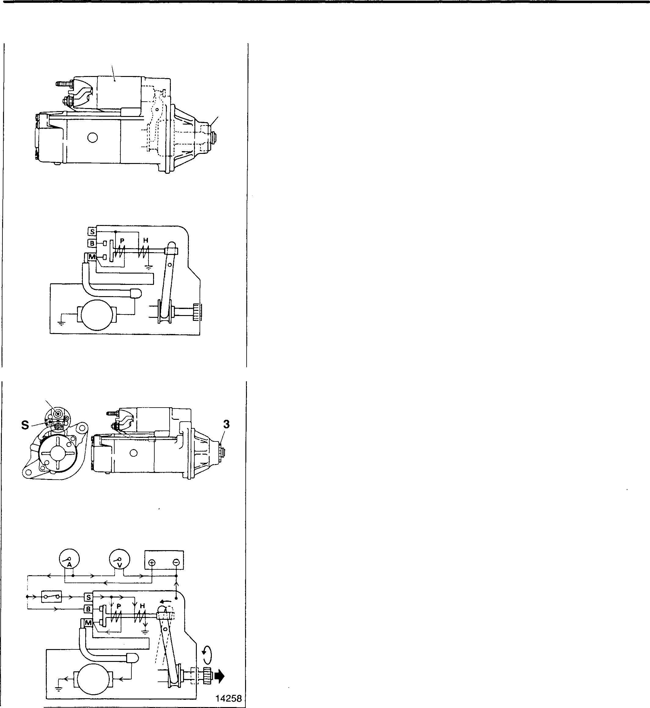
When the switch C is set to ON, current is supplied to both the pull-in coil P and holding coil H. When the large current from theDCpowersupply Dissuppliedfromterminal Bofthestarter to terminal M, the current to the pull-in coil is interrupted, and current flows to the holding coil only. Toprevent baking theholding coil, therefore, alltheoperations must be completed in less than 30 seconds.
• Measurethe current and rotating speed of the starter. Measure therotating speedofthe starter byilluminatingthepinion 3 with astroboscope.
• Setthe switch C to OFF tostopsupplyingcurrent to the starter.
• If thereading is outofthe standard value, disassemble and check thestarter.
5
STARTER <24V-5kW>
14266 14257 B 10767 A V D 54-98
(2) Pinion gap
[Inspection]
• Wire the starter as shown.
C: Switch
D: Switch
E: Cable
M: Starter terminal M
S: Starter terminal S
• The following operations are performed by supplying current to the starter. It is therefore necessary that the series of operations up to completion of measurement of the pinion gap is completed in less than 30 seconds.
• Set the switch C and switch D to ON to supply current to the starter. At the time, the pinion 3 will spring out and rotate.
• Immediately (in less than5seconds) after the pinion has started rotation, set the switch D to OFF stop rotation of the pinion.
CAUTION_&-------------
When the switch Cand switch Dare set to ON, current is supplied to both the pull-in coil P and holding coil H. Since wiring is such that no voltage is applied to terminal B of the starter, current flows to the pull-in coil during rotation of the pinion 3. Toprevent baking the pull-incoil, therefore, it is necessary that the switch Eis set to OFF immediately (in less than 5 seconds) after the pinion has started rotating.
• Lightlypushtheendoftheoverrunning clutch 38 inandmeasure the amount F theclutchmovesin theaxialdirection (piniongap).
• Set the switch C to OFF to stop supplying current to the starter.
• Ifthereadingisoutofthestandardvalue, adjustbythefollowingprocedures
[Adjustment]
• Remove the magnet switch 5 from the front bracket assembly 25.
• Adjust by changing the thickness of shim 6. Increasing the number of shims reduces the pinion gap F.
Types of shims: 0.25, 0.5 mm
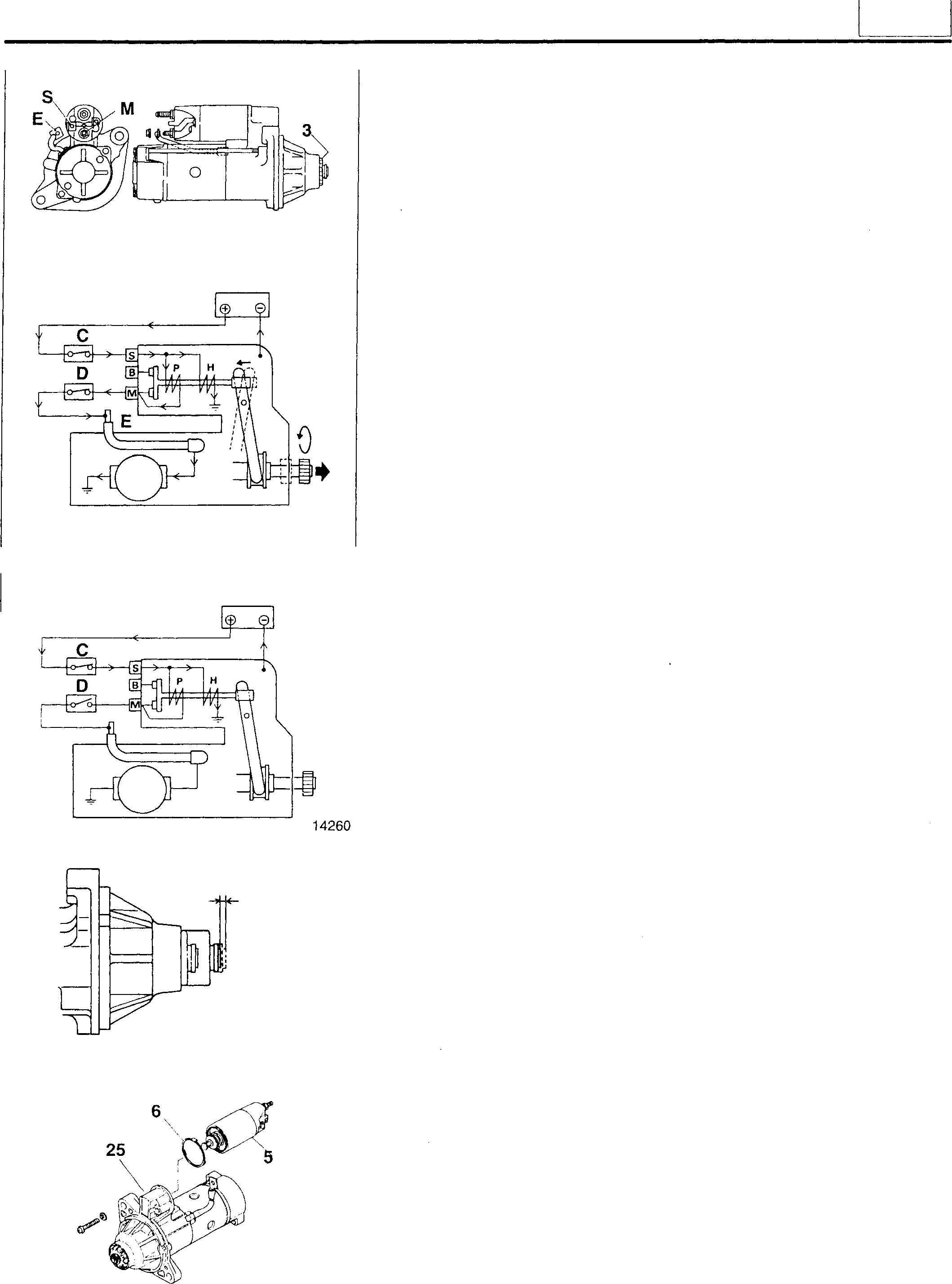
10768 DC24V 14259 DC24V F .. 10769 10770
54
5../--99
STARTER <24V-5kW>
[II Pinion
(Removal]
To removethepinion 3, itis necessary to supply current to thestarterand let the pinion spring out.
CAUTION.&_--------------
• Whencurrentissuppliedtothestarter,thepinion willspringout and rotate. Be careful not to touch it by hand.
• The magnetswitch 5 may be very hot after the end of inspection. Be careful when you touch it.
• Thetimeduringwhichcurrentissuppliedtothe startershouldbe limited to 10 seconds or less on the pull-in coil P side and 30 seconds or less on the holding coil H side. If current is supplied to the coils for a longer period, the coils will be overheated and baked.
• Make sure that the pinion is made to spring out by supplying currenttothestarter. Ifthepinionisforcedoutbypullingthelever 27 without supplying current to the starter, the front bracket 32 and lever could be damaged by the impact produced when the stopper ring 1 is removed.
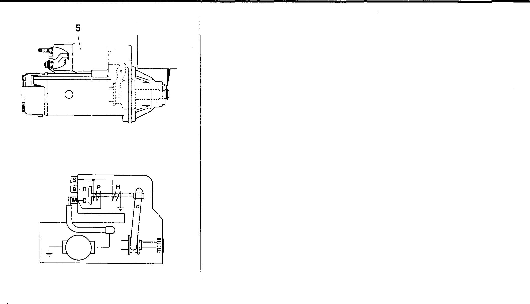
• When current is supplied to the starter, a large current that exceeds 100A will flow. When the starter is inspected, therefore, use thick cables like booster cables. Check to ensure that all the connections are tight and secure.
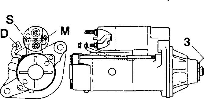
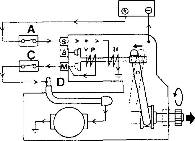
• Wire the starter as shown.
A: Switch
B: Starter terminal B
C: Switch
D:Cable
M: Starter terminal M
S: Starter terminal S
• The following operations are performed by supplying current to the starter. It is therefore necessary that the series of operations up to removal of the pinion 3 is completed in less than 30 seconds.
• Setthe switch A and switch C to ON to supplycurrentto the starter. At the time, the pinion 3 will spring out and rotate.
--,-,.�-\-, rJ j,
54-100
14267 14257 10768 DC24V 14259
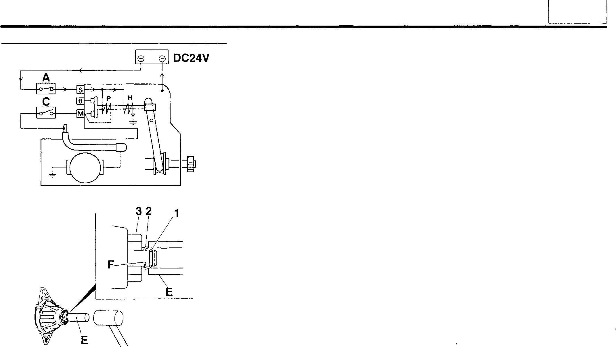
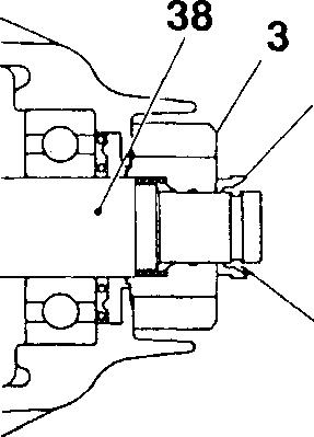
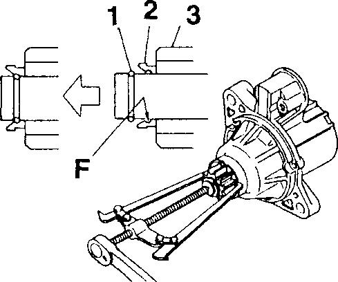
• Immediately (in less than 5 seconds) after the pinion 3 has started rotating, set the switch Cto OFF to stop rotation of the pinion.
CAUTION&-------------
WhentheswitchA and switchCare set toON, currentissupplied to both the pull-in coil P and holding coil H. Since wiring is such thatnovoltageisappliedtoterminal Bofthestarter,currentflows to the pull-in coil during rotation of the pinion 3.
To prevent baking the pull-in coil, therefore, it is necessary that the switch Cis set to OFF immediately (in less than 5 seconds) after the pinion has started rotating.
• Set the pipe-like tool E on the pinion stopper 2.
• LightlystrikethetoolEwithahammertoremovethestopperring1 from the ring groove F of the pinion stopper 2.
• Remove the stopper ring 1 and remove the pinion 3.
• Set the switch A to OFF to stop supplying current to the starter.
CAUTION&-------------
Whenthe power supplytothestarter is stopped, the pinion 3may move in and the stopper ring 1 may fit in the ring groove F of the pinion stopper 2 again.
In this case, repeat the operations by supplying current to the starter.
[Installation]
To install the pinion 3, it is not necessary to supply current to the starter.
• Install the pinion stopper 2 and pinion 3 on the overrunning clutch 38 in the direction shown.
• Set the stopperring 1 inthering groove F oftheoverrunningclutch 38.
• Pull the pinion 3stronglyto make sure that the stopper ring 1 securely fits in the ring groove F of the pinion stopper 2.
14260 10779 2 (� F 10781 10782 54
54-101
STARTER <24V-5kW>
W Magnet switch
[Installation]
Installthemagnetswitch5onthelever27withterminalSinthedirection shown.
[Inspection]
(1) Open circuit teston coil
• ChecktoensurethatthereiscontinuitybetweenterminalsSand M.
• Ifthereis no continuity, replace the magnet switch 5.
• Check to ensure that there is continuity between terminal M and body A.
• Ifthere is no continuity, replace the magnetswitch 5.
(2) Contact fusion check
• ChecktoensurethatthereisnocontinuitybetweenterminalsBand M.
• Ifthere is continuity, replace the magnet switch 5.
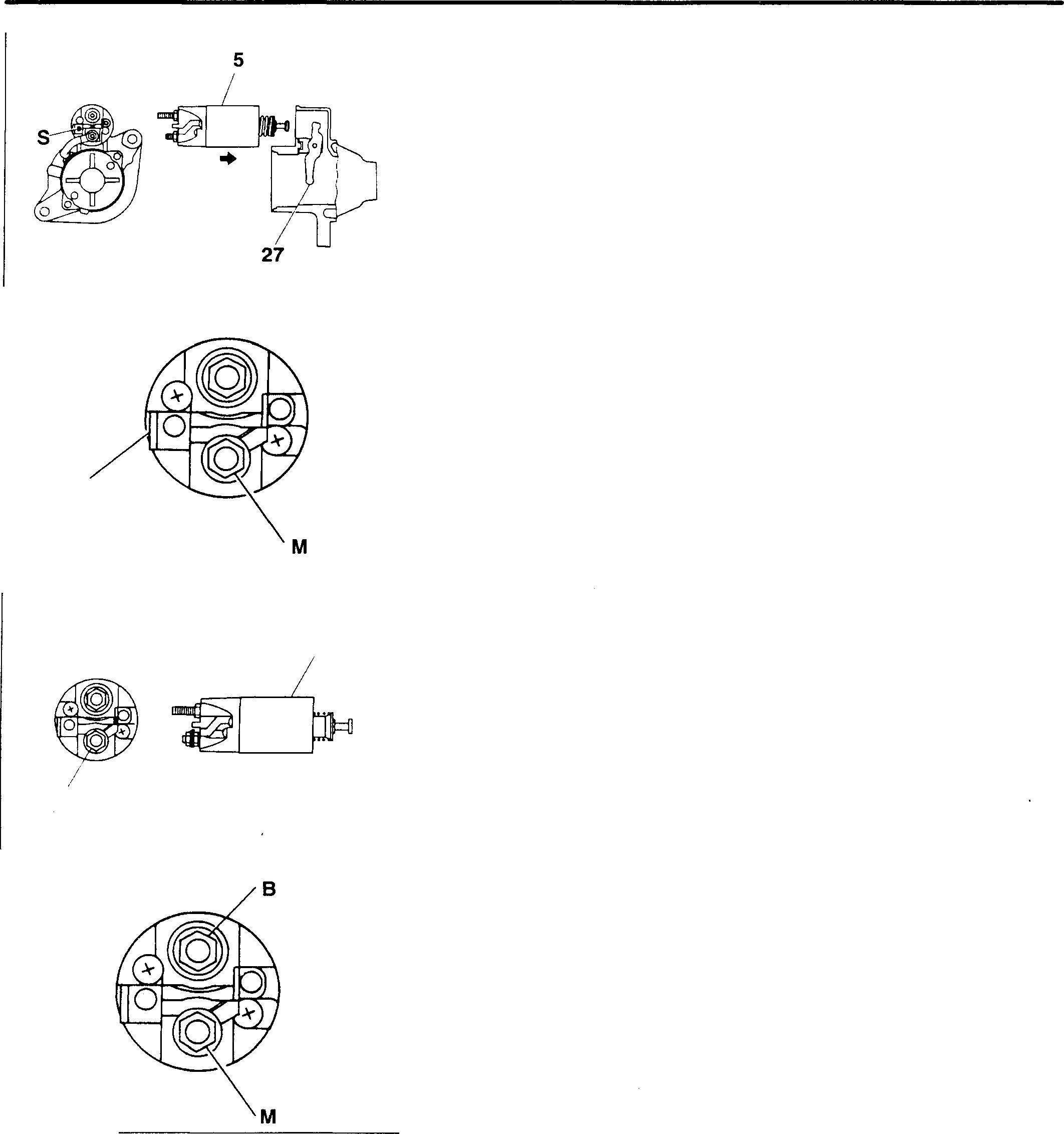
(3) Contact contacting check
• Pushtheendofthemagnetswitch5intoclosetheinternalcontact. Inthisstate, checktoensurethatthereiscontinuity betweenterminals Band M.
• Ifthere is no continuity, replace the magnetswitch 5.

10771 s 10773 A M 10774 10775 8 -�· M 10776 54-102
[fil Installation of rear bracket A:Alignmentmarks
� Installation of conical washer
Installtheconicalwasher10 intheillustrated directionintherearbracket 9.
[!3J Removal of yoke & brush holder assembly
To remove the yoke & brush holder assembly, proceed as described below, while using care to prevent damage to the commutator A of the armature assembly 17 bythe brushE;is 14 and 15.
• Keepthebrushes14 and15apartfromthecommutatorAandholdthe brushspring 13 alongsidethe brushes.
• Removethe yoke & brush holder assembly 11 fromthe front bracket assembly25.
CAUTION&-------------
Whenthe yoke & brushholder assembly11 isremoved, do not tilt itdownward. Otherwise,the armature assembly18mayfalldown.
• For installation, reversethe order ofremoval.
� Inspection of brush spring
• Usenewbrushes 14 and 15 andmeasuretheloadatthemomentthe brushspring 13 leavesthe brushes as shown.
• If thereadingis less thanthe limit, replacethebrushspring 13.
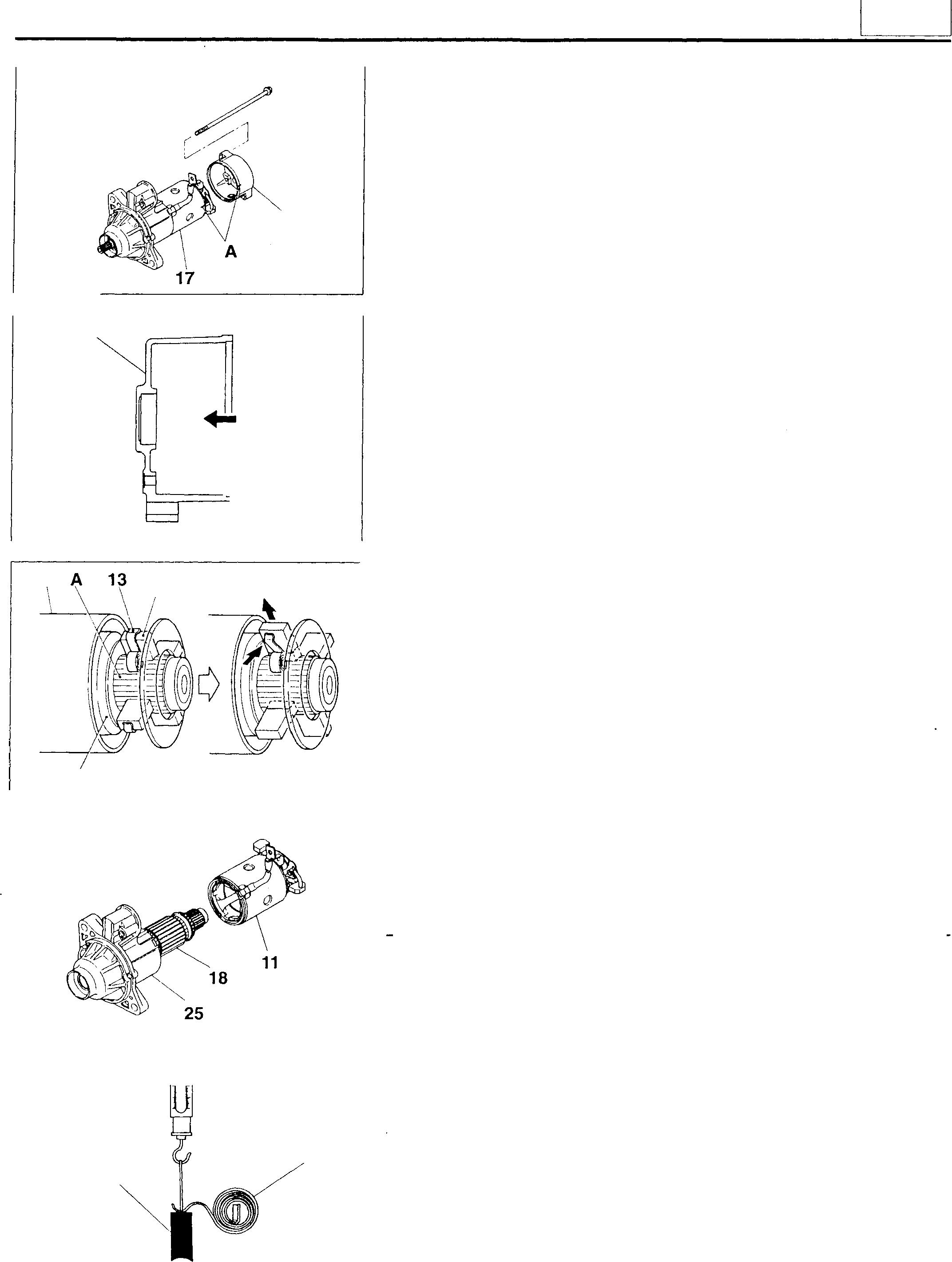
9 13528 9
10766 11 14,15 18 16083 20017 13 14,15 02466
(
54
54-103
STARTER <24V-5kW>
�� Inspectionof brush
(1) Length of brush
If the reading is less than the limit, replace the brushes 14 and 15.
CAUTION&--------
Toreplacethebrush814,replacethebrushholderassembly16.
(2) Commutator contacting surfaces
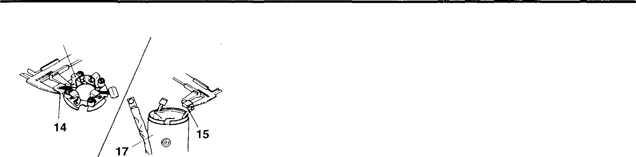
If the contacting surfaces are rough or unevenly worn, repair with emery paper (#300 to 500).
@] Inspectionof brush holder assembly
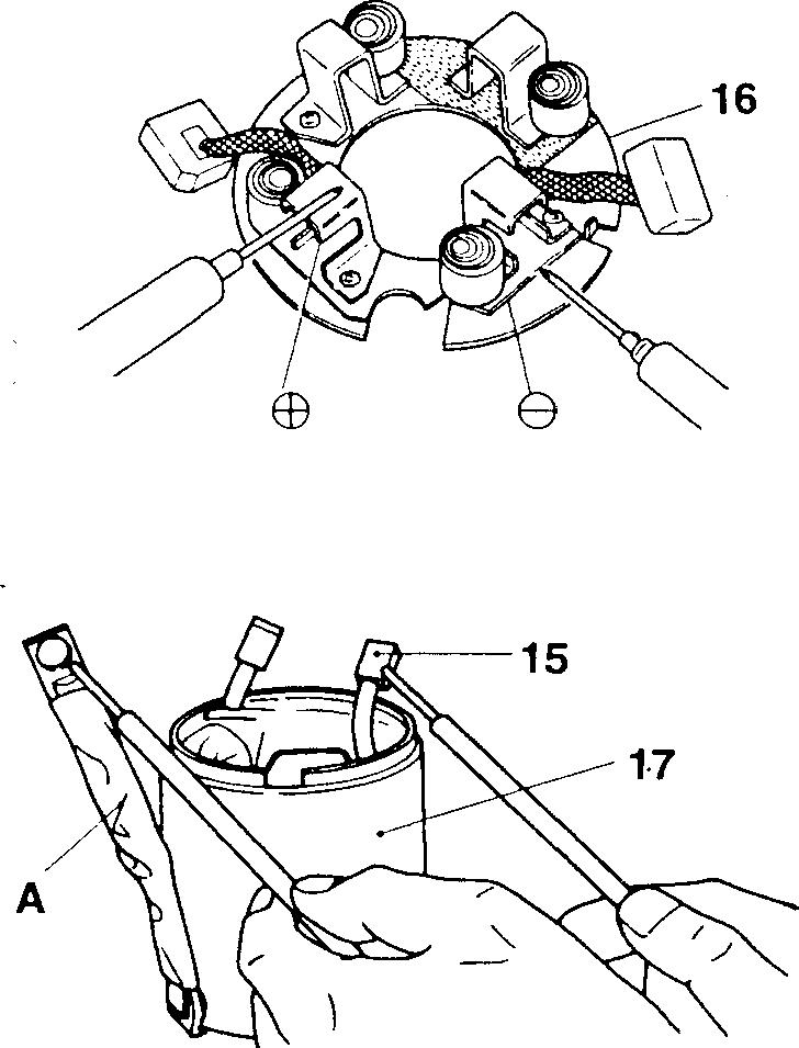
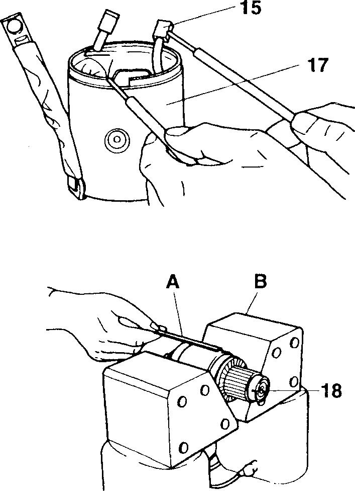
• Check to ensure that there is nocontinuitybetween the EB side brush holder and 8 side holder plate.
• If there is continuity, it means a short circuit. Replace the brush holder assembly 16.
[Izj Inspectionofyoke assembly
(1) Open circuit teston coil
• Check to ensure that there iscontinuitybetweencable A and brush EB 15.
• If there is no continuity, it meansanopen circuit. Replace the brush EB 15 or yoke assembly 17.
(2) Earth test on coil
• Checktoensure thatthereisnocontinuitybetween theyokeassembly 17 and brush EB 15.
• If there is continuity, it means a short circuit. Check the insulation. If repairisimpossible, replace the brush EB15oryoke assembly 17.
� Inspectionof armature assembly
(1) Short circuit test on coil
• Bring the iron piece A close to the armature assembly 18, keeping it in parallel.
• Slowly rotate the armature assembly 18 by hand.
• If the iron piece A is attracted or vibrates, it means a short circuit. Replace the armature assembly 18.
16
02465
02467
02477
02471 54-104
02478
(2) Earth teston coil
• Checktoensurethatthereis nocontinuity betweenthecommutator C and core D (or shaft portion E).
• If there is continuity, it means a short circuit. Replace the armature assembly 18.
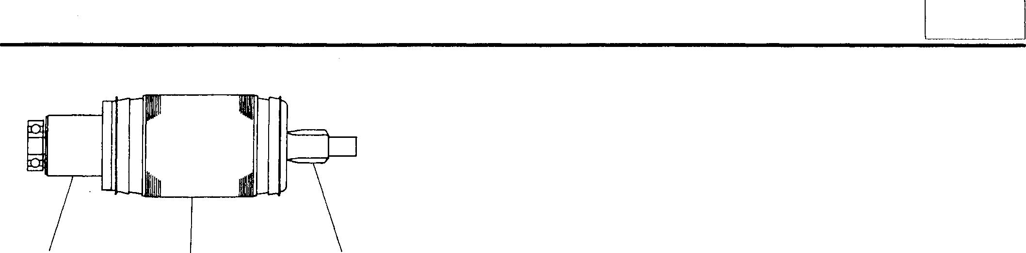
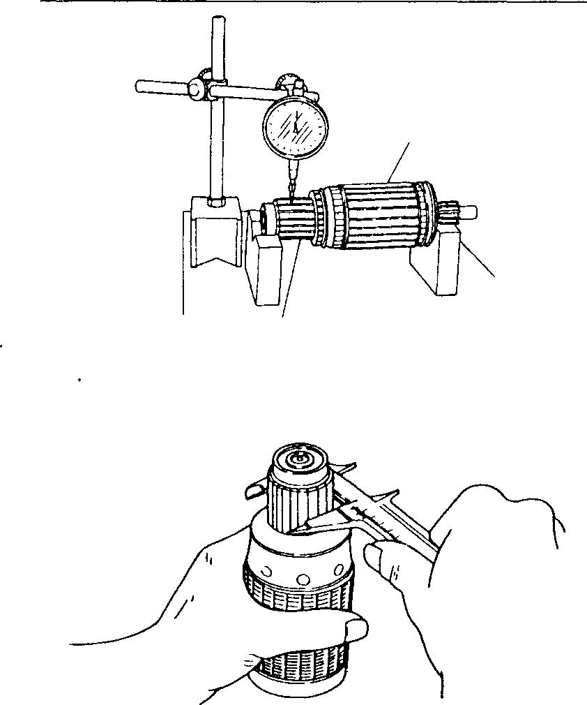
)8
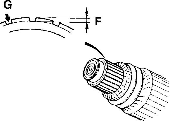
(3) Runoutofcommutator
If the reading is more than the limit, repair the outside diameter of the commutator portion C of the armature assembly 18 within the limit.
(4) Condition of commutator surface
• If the surface is rough or unevenly worn, repair with emery paper (#300 to 500).
• After the repair, be sure to check the runout of the commutator portion C.
(5) Outside diameter ofcommutator
Ifthereading ismorethanthelimit, replacethearmatureassembly 18.
(6) Depth ofmold between segments
Before inspection, clean the mold portions.
• If the reading is less than the limit, repair or replace the armature assembly 18.
F: Depth of mold
• Make repairs by grinding the illustrated portion G.
• If the mold portion is as shown, repair or replace the armature assembly 18.
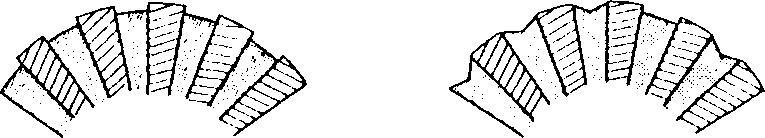
C D E 13329
C 13330 02474 16078 Good No good 02476 54
54-105
� Installation of lever
Installthelever27intheillustrateddirectionontheoverrunningclutch38.
� Installation of front bearing
• Beforethe frontbearing 30 is press-fitted, install the dustseal 31.
• Press-fitthefrontbearing30 inthefrontbracketwithapress,usingthe pipe-like tool A.
• Stake the front bracket 32 side.
CAUTION_&-------------
Avoid staking the previously staked points B.
C:Stakingpoints(4 places)
� Inspection of overrunning clutch
Performthefollowingchecks.Ifthereisanythingwrong,replacetheoverrunningclutch 38.
• ChecktoensurethatwhentheshaftAismadetorotateinthedirection B, itrotatessmoothly.
• ChecktoensurethatwhentheshaftAismadetorotateinthedirection C, itislocked.
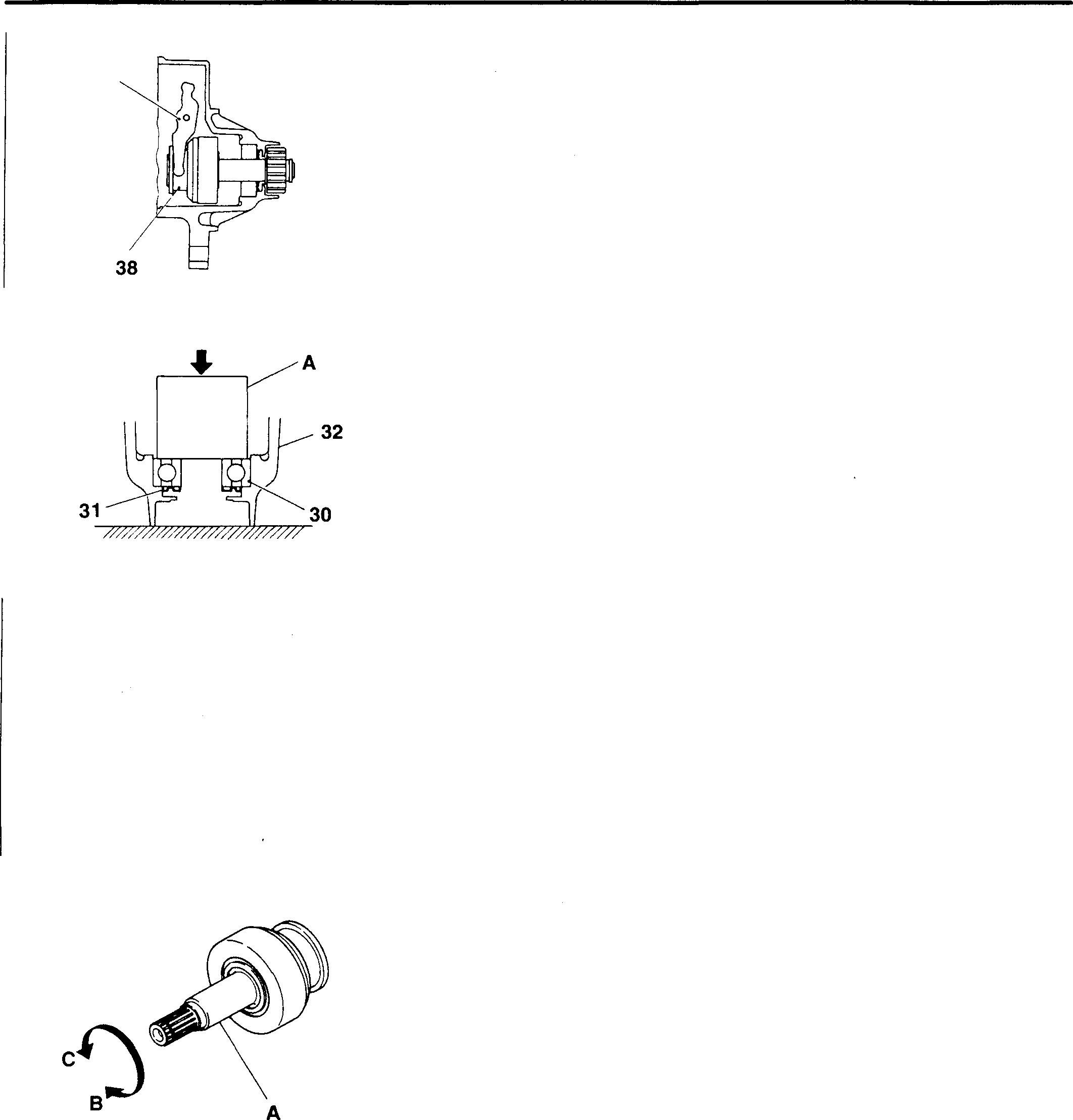
54-106 27 (; 32 c @:B"/�' 30
STARTER <24V-5kW>
ft
10778
13325
13326
13328
Pages 54-107 to 54-129 are deleted as they are not i"n use.
PREHEATER CIRCUIT
<24V (air heater) specification> 1
<24V (glow plug) specification> 1
<12V specification> 1
1 Starter switch
2 Heater relay (or glow relay)
3 Heaterindicator (vehicleswithairheater)
Glow plug indicator (vehicles with glow plugs)
4 Intake air heater
5 Glow plug
6 Battery relay (24V specification)
Battery switch (12V specification)
7 Battery
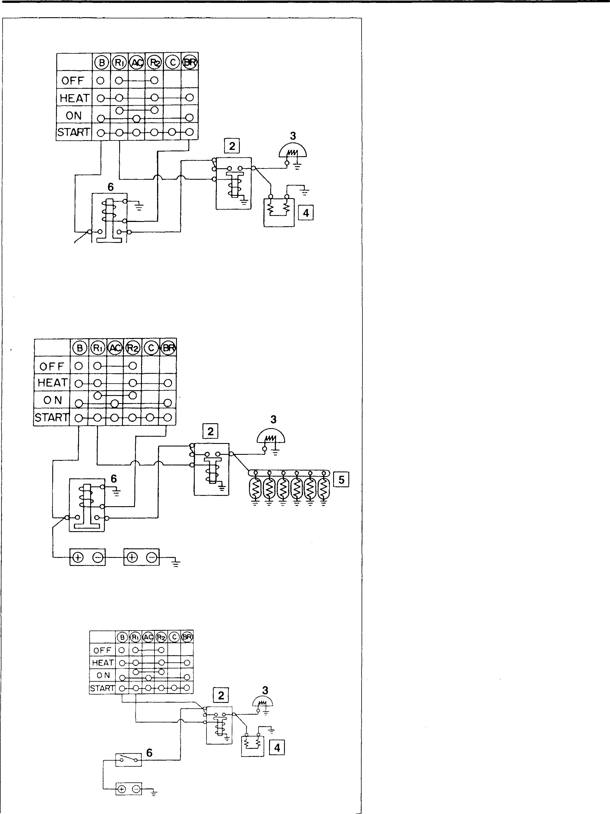
� 7
7
7 54-130
18461
18462
18463
♦ Service procedure
� Inspection of heater relay {or glow relay)
(1) Inspection of heater
If the fuse A is blown, replace it with one having the same amperage stamped on the fuse.
(2) Inspection of main body
<24V specification>
• Perform continuity checksaccording to the following table. G)
Whencurrent is supplied
0--0 There iscontinuity between terminals.
®-----0 Terminalsto which24V DC isapplied
A: Fuse
• Ifthereisanything wrong, replacetheheaterrelay (or glowrelay) 2.
<12V specification>
• Perform continuity checksaccording to the following table.
Whenno current issupplied
Whencurrentis supplied
0--0 There iscontinuity betweenterminals.
®-----0 Terminals to which24V DC isapplied @
• If thereisanything wrong, replace the heaterrelay (or glow relay) 2.
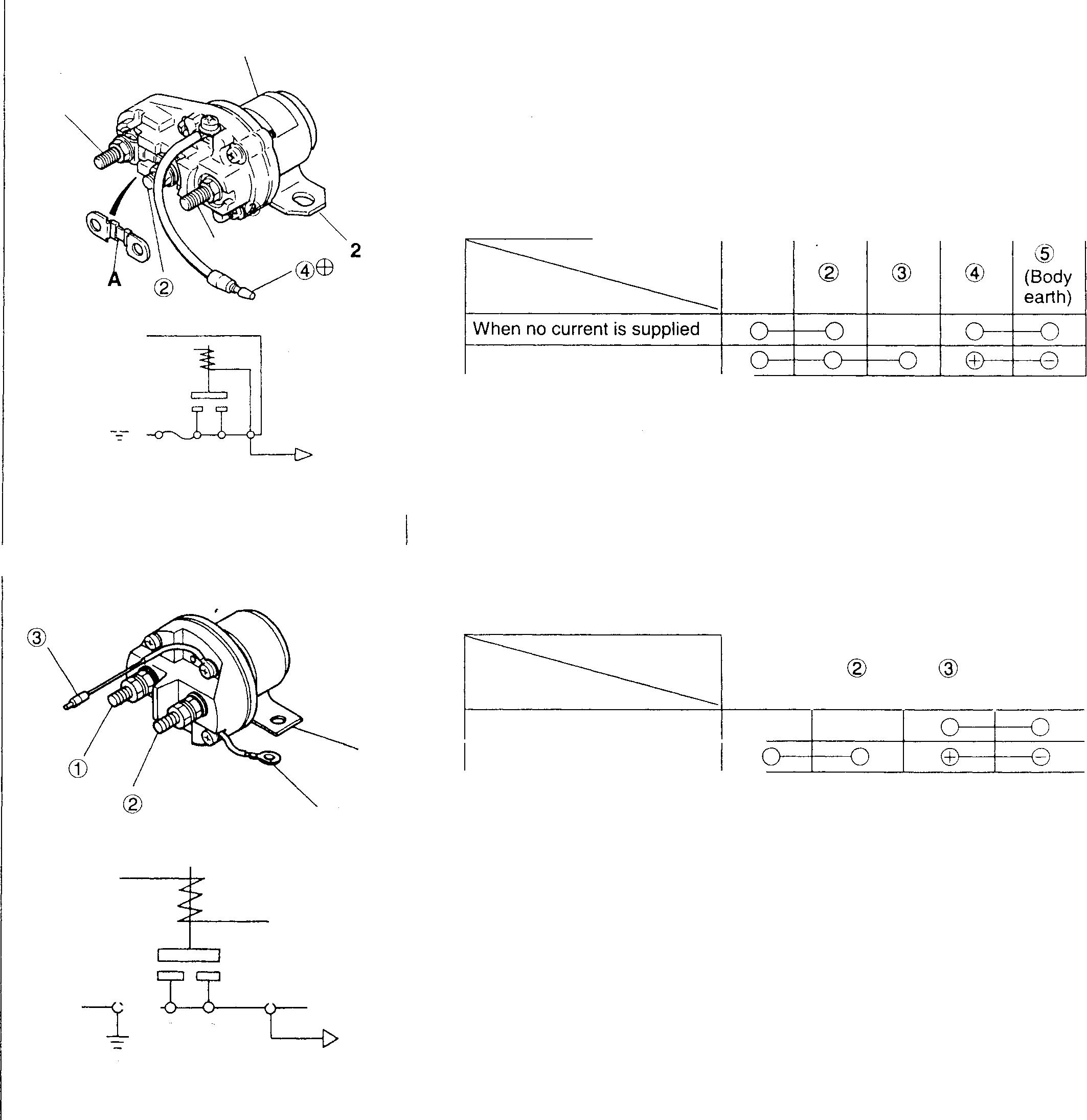
54 Service standards Location Maintenance item Standard value Limit Remedy Resistance of glow plug atnormaltemperature 3.8Q - Replace G) @e (� G) Cg)@ 8 @ 8 CD C2> @ED 17543 2 @ �)ED 18464
G)
54-131 Mitsubishi 6D16TLEA engine parts contact: email: engineparts2@gmail.com Phone: 269 673 1638 Text: 269 760 8652
PREHEATER CIRCUIT
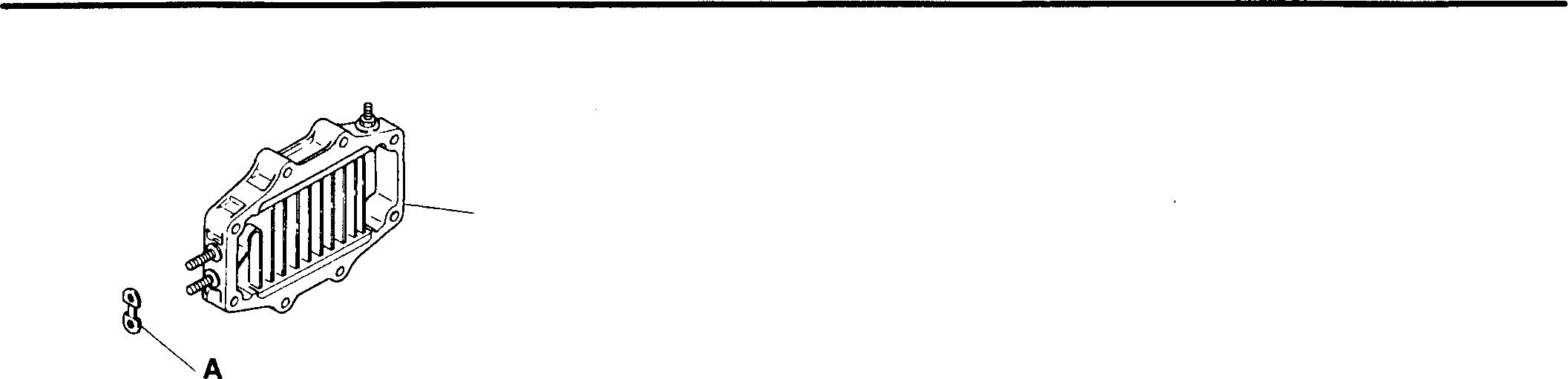
4
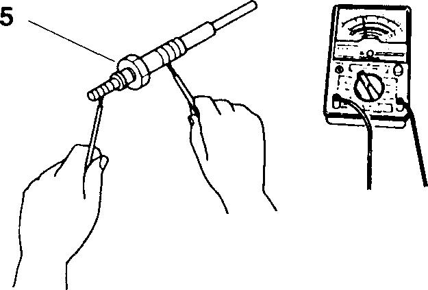
[!] Inspection of intake air heater
(1) Inspection of fuse
If there is anything wrong, replace the fuse A (127A).
A: Fuse (127A)
(2) Inspection of main body Checktheterminalsforlooseness, andtheheaterelementfordamage and loose contact with the glass.
• If there is anything wrong, replace the intake air heater 4.
[]] Inspection of glow plug
• Measure the resistance of the glow plug 5 as shown.
• If the reading is out of the standardvalue, replace the glow plug 7. (I]Gr11
Mitsubishi 6D16TLEA engine parts contact:
email:
Phone: 269 673 1638
Text: 269 760 8652
18465
54-132
02513
engineparts2@gmail.com
54
54-/33
MEMO
ENGINE STARTER CIRCUIT
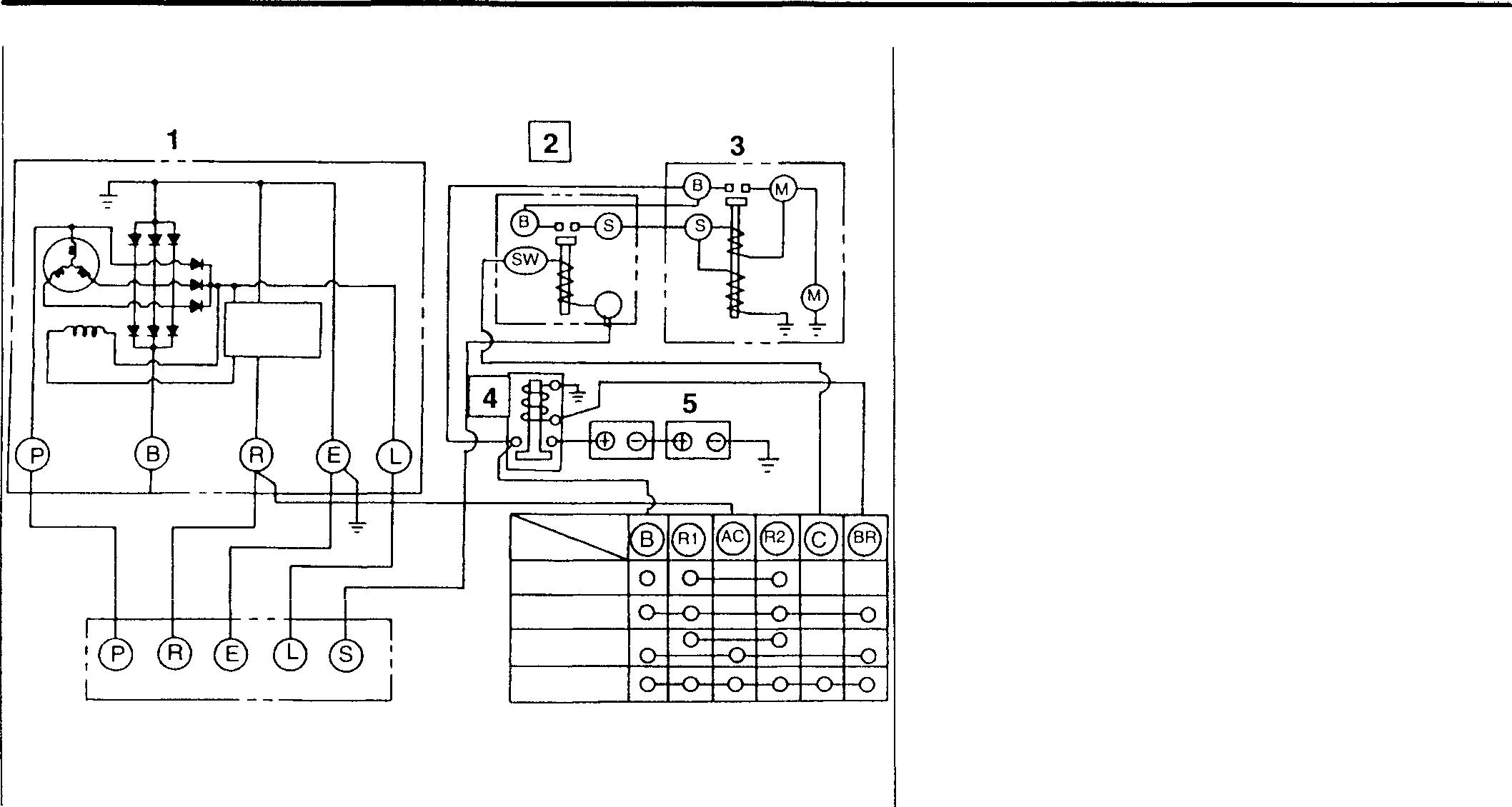
1 Alternator
Starter relay
Starter 4 Battery relay (24V)
switch (12V)
Battery
Starter switch
Safety relay Standard value Limit Approx. 200n
♦ Service procedure
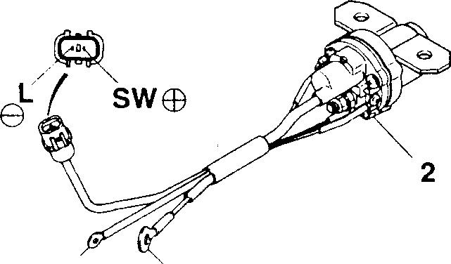

@] Inspection of starter relay -
• Perform continuity checks according to the following table.
When no current is supplied
When current is supplied 0----0 There is continuity between terminals. ©--------8 Terminals to which 24V DC is applied SW
• If there is anything wrong, replace the starter relay 2.
W Inspection of safety relay
Measurethe resistance valuebetween terminals R-L. Ifthereadingisout of the standard value, replace the safety relay 4.
Mitsubishi 6D16TLEA engine parts contact:
email: engineparts2@gmail.com
Phone: 269 673 1638
Text: 269 760 8652
Service standards Location 4 p E s/ 54-134 Safety relay '8 s Maintenance item 18017 17530 6 18466
2
3
Battery
5
6
7
7
B
s
Remedy Replace L
I 54 I MEMO 54-135
AUTOMATIC STOP SYSTEM (SHUTDOWN)
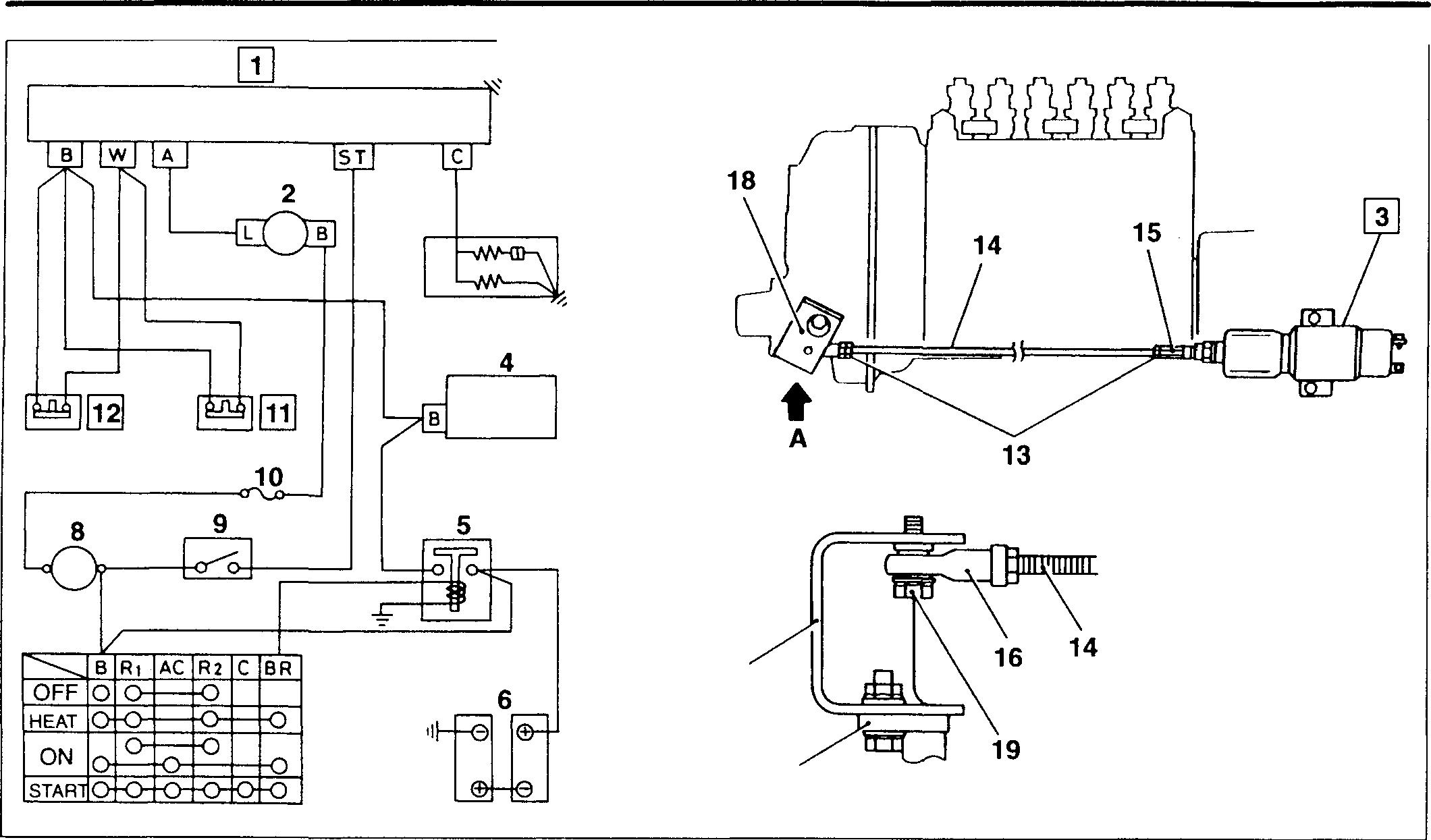
3 18 17 7 18737 View A 18819 1 Solenoid relay 8 Ammeter 14 Rod 2 Alternator 9 Stop switch 15 Swivel joint 3 Solenoid 10 Fuse box 16 Ball joint 4 Starter 11 Engine oil pressure switch 17 Base lever 5 Battery relay 12 Coolant temperature sensor 18 Stop lever 6 Battery 13 Lock nut 19 Flange bolt 7 Starter switch Service standards Unit: mm Location Maintenance item Standard value Limit Remedy 1 Solenoid Delay time at start 18 ± 5 secs. - Replace relay (after application of 28.5V to terminal B, and 28.5V to terminal A) Delay time at stop 30 ± 5 secs. - Replace (after application of 24V to terminal B and 0V to terminal A) 3 Solenoid Clearance between base lever and 1.2 ± 0.2 - Adjust case stopper Holding coil current 0.5A or less - Replace 11 Engine oil pressure switch operating pressure 78 ± 20 kPa {0.8 ± 0.2 kgf/cm2} - Replace 12 Coolant temperature sensor City water cooling 95 ± 2°c - Replace operating temperature Radiator cooling 101 ± 2°c - Replace 54-136 Mitsubishi 6D16TLEA engine parts contact: email: engineparts2@gmail.com Phone: 269 673 1638 Text: 269 760 8652
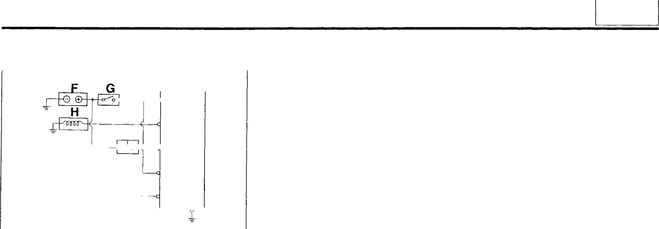
♦ Serviceprocedure
OJ Solenoid relay
Wire as shown at left and perform the following inspections.
F: Power supply
G: Switch
H: Solenoid (or coil load: 30 ± 3A)
J: Switch
K: Switch
L: Power supply
(1) Inspection of oil pressure timer
• Connect 28.5V DC power supplies to F and L.
• Set the switch G to ON.
• Set the switch K to ON and simultaneously measure the time required before the solenoid Hoperates.
• If the reading is out of the standard value, replace defective parts.
NOTE
When the timer is to be re-tested, allow a recovery time of five minutes as the discharge finishing time of the capacitor in the solenoid relay 1.
(2) Inspection of stop timer
• Connect 24V DC power supply to F and 28.5V DC power supply to L.
• Set the switches G and Kto ON.
• Set the switch Kto OFF 5 seconds after the solenoid H has operated. (It takes 5 seconds for the generating voltage of alternator· 2 to disappear after the activation of the solenoid.) At the same time, measure the time required before the solenoid returns.
• If the reading is out of the standard value, replace defective parts.
NOTE
When the timer is to be re-tested, allow a recovery time of five minutes as the discharge finishing time of the capacitor in the solenoid relay.
(3) Manual stop timer
• Connect 24 V DC power supply to F.
• Set the switch J to ON to operate the solenoid H.
• Measure the timerequired for the solenoid H to return after setting the switch J to OFF.
• If the reading is out of the standard value, replace defective parts.
+-----<l 8 J C '---�i--O-'--o--4-------<J $T L K w A E 18820
54
54-137
AUTOMATIC STOP SYSTEM (SHUTDOWN)
@] Solenoid
[Installation]
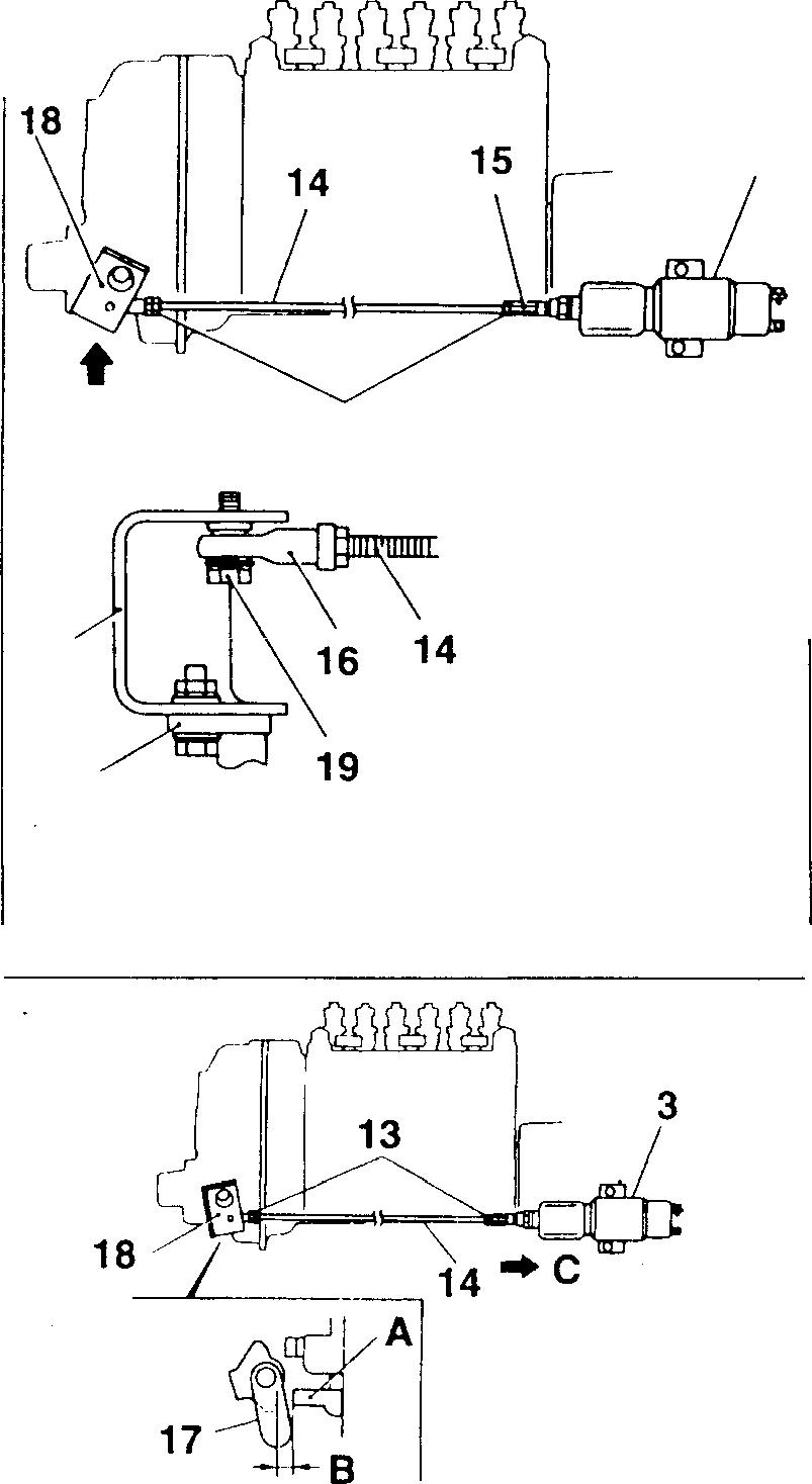
3
• Temporarily tighten the ball joint 16 to the rod 14 and thread the other end six to ninetimesintotheswiveljoint 15 and secureitwith locknuts 13.
• Checktoensurethattherotating portionsoftheswivel joint 15 and ball joint 16 smoothly rotate.
• Mount the solenoid 3 on the engine.
• Rotate the ball joint 16 to adjust the length of rod 14, place the stop lever 18 in the normal use position, and install the ball joint with the flange bolt 19.
[Adjustment]
• Adjust the length of the rod 14 so that the clearance 8 between the baselever 17 and case stopper A willhavethestandard valuewith the solenoid 3 in operation.
C: Solenoid moving direction
• Firmly tighten the lock nuts 13 at both ends of the rod 14 and stop operation of the solenoid.
CAUTION.&_-------------
Do not continue to supply current to the solenoid3for more than 20 seconds. Otherwise the solenoid may be burned.
• Switch the switch of the circuit between ON and OFF repeatedly two or three times and check the following items.
CAUTION.&_------------
Do not switch the switch rapidly between ON and OFF.
• Check to ensure that the stop lever 18, rod 14 and solenoid 3 move smoothly.
• Check to ensure that the clearance B between the base lever 17 and case stopper A have the standard value.
A 13 18 17
A
54-138
View
18819 18824
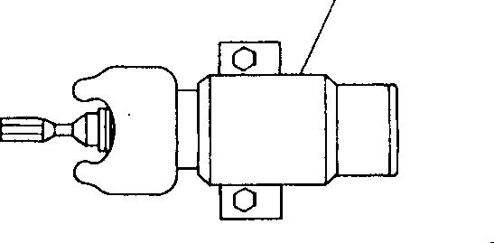
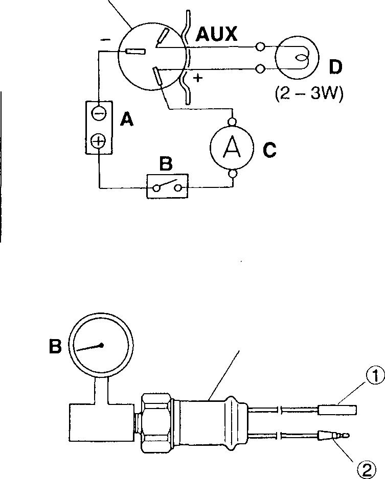
[Inspection]
Wireasshownatleftandperformthefollowingchecks. NOTE
The checks can be performed by use of either the ammeter C or lampD.
A: Powersupply
B: Switch C:Ammeter
• Settheswitch B toON.
• Ifthereadingoftheammeter C afteractivationofsolenoid 3 isoutof thestandardvalueorthelampDdoesnotlight,replacethesolenoid.
CAUTION_&------------
When the check lamp does not light, do not continue to supply currenttothesolenoid3 formorethan 20seconds. Otherwisethe solenoid may be burned.
[TI] Inspection of engine oil pressure switch
Performthefollowingchecks.Ifdefective,replacetheengineoilpressure switch 11.
• Undertheconditionwherenoairpressure A isappliedtotheengine oilpressureswitch11, checktoensurethatthereiscontinuitybetween theterminalsCDand®.
• Slowlyapplytheairpressure A totheengineoilpressureswitch 11, beginningatOkPa(0kgf/cm2).
WhenthereisnomorecontinuitybetweentheterminalsCDand®, measuretheairpressureandchecktoensurethattheairpressurehas thestandardvalue.
B:Airpressuregauge

� Inspection of coolant temperature sensor
• Putthecoolanttemperaturesensor12inacontainerfilledwithengine oil.
• Beforeraisingtheoiltemperature,checktoensurethatthereisnocontinuitybetweentheterminalsCDand®.
• Slowlyraisetheoiltemperatureandstirtheengineoilwell.
• Measurethetemperatureatthetimewhenthereiscontinuitybetween theterminalsCDand®.
• Ifthereadingisoutofthestandardvalue,replacedefectiveparts.
NOTE
When the oil temperature is near the operating temperature, slowly heat the oil. (When the operating temperature -5°C is reached, leave italonefor five minutes, andthenraisetheoil temperature at a rate of 1°C in two or three minutes.)
3 AUX (� (+) 18821 3 18822 11 AQ 18825 e,� �,-0 0 0 0 0 18826 54
Mitsubishi 6D16TLEA engine parts contact: email: engineparts2@gmail.com Phone: 269 673 1638 Text: 269 760 8652
54-139
AUTOMATIC STOP SYSTEM <RUN-ON>
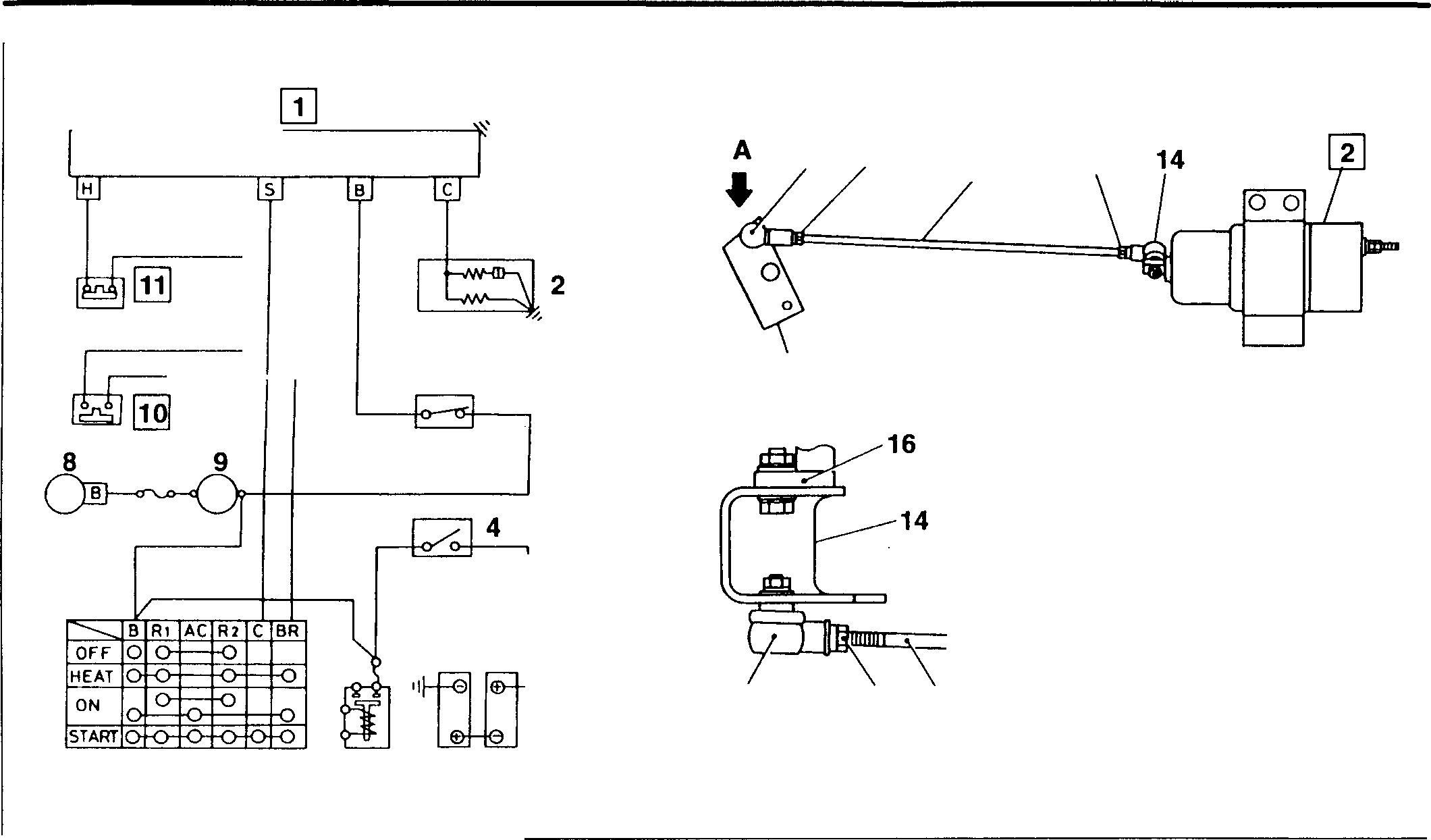
Mitsubishi 6D16TLEA engine parts contact:
email: engineparts2@gmail.com
Phone: 269 673 1638
Text: 269 760 8652
3 7 6 5 1 Solenoid relay 2 Solenoid 3 Stop switch 4 Battery switch 5 Battery 6 Heater relay Service Standards 14 14 12 15 12 13 View A 18745 7 Starter switch 8 Alternator 9 Ammeter 10 Engine oil pressure switch 11 Coolanttemperaturesensor 13 12 13 14 15 16 Location Maintenance item Standard value 1 Solenoid relay delaytime 30±4secs. 2 Solenoid Pointerclearance 0.8to1.5 Clearancebetweenstopleverand 0.4to 0.5 externalstopper Holding coil cur- 24V 1A orless rent 12V 5A or less 12 Lock nut Rod Balljoint Stop lever Base lever 11 Engine oil pressure switch operatingpressure 78±20 kPa {0.8± 0.2 kgf/cm2} 12 Coolant temperature sensor City watercooling 95±2°c operating temperature Radiatorcooling 101±2°c 54-140 0 0 18827 Unit: mm Limit Remedy - Replace - Replace - Replace - Replace - Replace - Replace - Replace - Replace
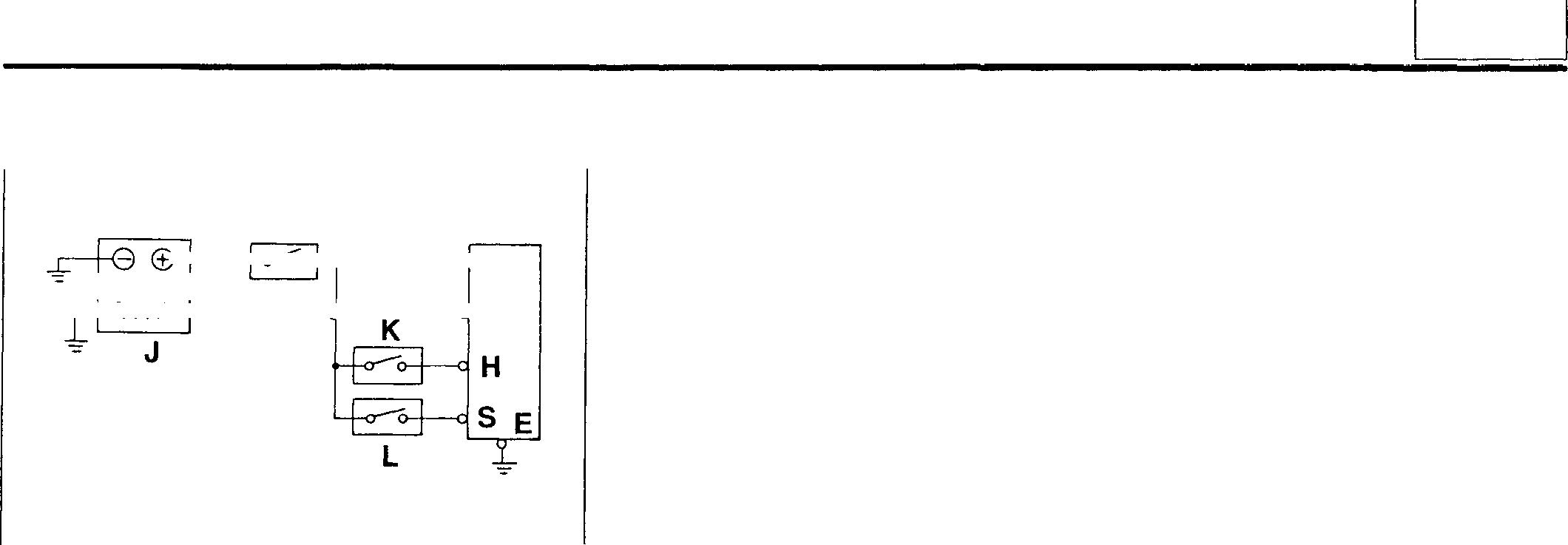
♦ Service procedure IT] Solenoidrelay
Wire asshownatleftand performthefollowingchecks.
F: Powersupply
G: Switch
J:Solenoid (or coilload: 30±3A)
K:Switch
L:Switch
(1) Inspection ofoperation ofsolenoid relay 1 and delay time
• ChecktoensurethatwhentheswitchesGand LaresettoON, the solenoidJ operates.
• Set the switch L to OFF and simultaneously measure the time required beforethesolenoid J isdeactivated.
(2) Inspection ofrelay holding time
• SettheswitchesGand LtoON. AfterthesolenoidJ hasoperated, settheswitch Kto ON.
• Set the switch L to OFF and check to ensure that the solenoid J stays intheoperatingstate for more than 30 seconds.
• After checking that thesolenoid J is in the operating state, set the switch Kto OFFto checkthat thesolenoid is deactivated.
[fil Solenoid
[Installation]
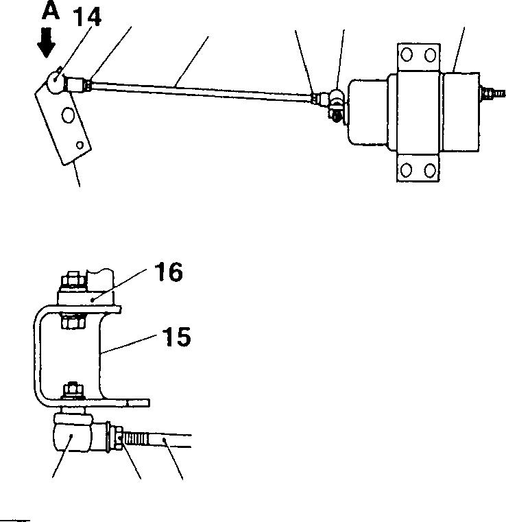
T• Installtheballjoint14totherod 13andtemporarytightenwithlocknut 12.
• Checkto ensure thatthe balljoint 14 moves smoothly.
• Installthesolenoid 2 to theengine.
• Withthestoplever15inthestopposition,installtherod 13. Adjustthe rod length by turningit.
[Adjustment]
• Removethecover of thesolenoid2.
• Apply thespecified voltageto solenoid2 and energize the solenoid.
• Check that the clearance A between the pointers of the solenoid is within the standard value.
14 F G 1 l---+-��o---1-.--------d B :====� -+rimllf'-+--------t'-----dc 12 13 12 14 2 15 View A 12 13 A 2
18828 18827 18831
54
54-141


• Withthesolenoid2keptenergized,adjusttheclearanceC betweenthe baselever 16 andthecasestopper Btothestandardvalueby turning the rod 13.
D: Solenoid moving direction
• Deenergize the solenoid 2.
• Firmly tightenthe lock nut 12.
• Switch the solenoid 2 between ON and OFF repeatedly two or three times (with approx. 1O seconds of internal) and check the following items.
CAUTION_&------------
Do not switch the solenoid rapidly between ON and OFF.
• Checktoensure thatthestop lever 15, rod 13 and solenoid 2 operate smoothly.
• Check to ensure that the clearances A and C fallwithin thestandard limits.
• Mount the coverof solenoid 2.
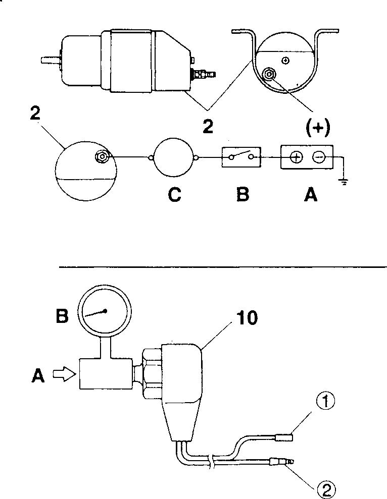
[Inspection]
Wire as shown atleft and perform the following checks.
A: Powersupply
B: Switch
C:Ammeter
• Setthe switch B to ON.
• Ifthereadingoftheammeter C afterthe activationofsolenoid 1 isout of the standardvalue, replace the solenoid.
[IQ] Inspection of engine oil pressure switch
Performthefollowingchecks. Ifdefective,replacetheengineoilpressure switch 10.
• Under the condition where no air pressure A is applied to the engine oil pressure switch 10, check to ensure that there is no continuity between the terminalsG) and®.
• Slowly apply the air pressure A to theengineoil pressure switch 10, beginning atO kPa (O kgf/cm2). Whenthereiscontinuity betweentheterminalsG)and®,measurethe airpressureandchecktoensurethattheairpressurehasthestandard value.
B:Air pressure gauge
Mitsubishi
Phone: 269 673 1638
Text: 269 760 8652
12 0 c� 2 16 18832 18829 18833 54-142
AUTOMATIC STOP SYSTEM <RUN-ON>
6D16TLEA engine parts contact: email: engineparts2@gmail.com
[TI] Inspection of coolant temperature sensor
• Putthecoolanttemperaturesensorinacontainerfilledwithengineoil.
• Beforeraisingtheoiltemperature, checktoensurethatthereiscontinuity between theterminalsG) and@.
• Slowlyraisetheoiltemperatureandstir theengineoilwell.
• Measurethetemperatureatthetimewhenthereisnomorecontinuity betweentheterminalsG) and@.
• If thereadingis outofthe standard value, replace defective parts.
NOTE
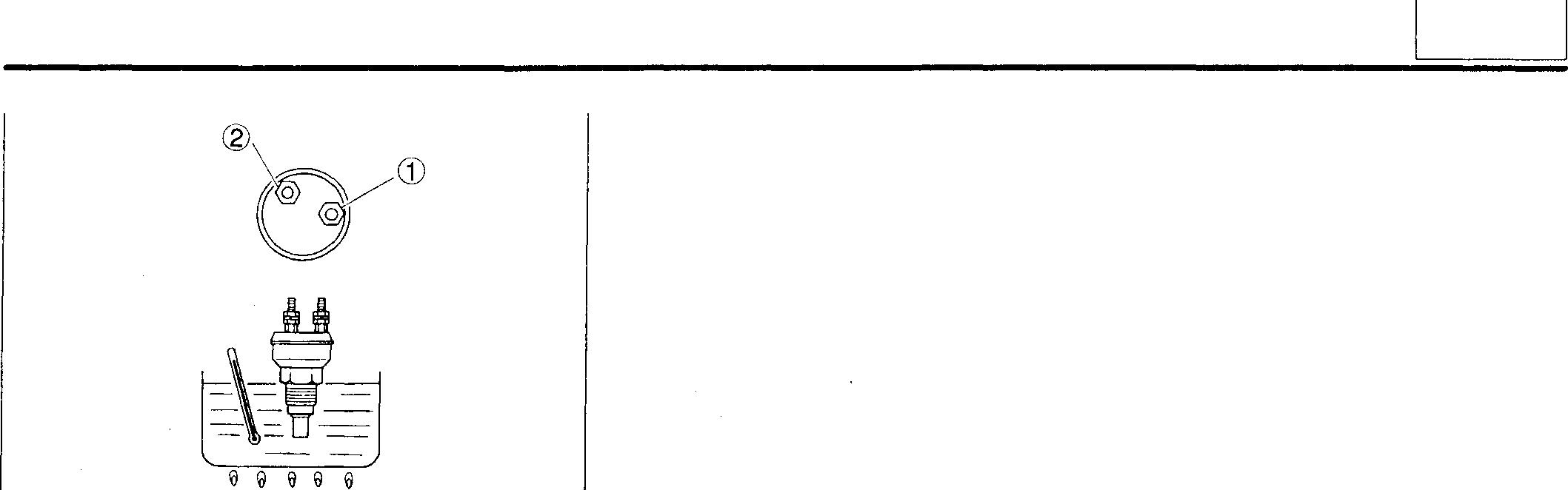
18826
When the oil temperature is near the operating temperature, slowly heat the oil. (When the operating temperature -5°C is reached, leaveitaloneforfive minutes, and thenraisetheoil temperature at a rate of 1°C in two or three minutes.)
Mitsubishi 6D16TLEA engine parts contact: email: engineparts2@gmail.com
Phone: 269 673 1638
Text: 269 760 8652
54
5.J-143
LAST PAGE
