This Shop Manual is published for the information and guidance of personnel responsible for maintenance of the Mitsubishi 6M60 series diesel engine, and includes procedures for adjustment and maintenance services.
We earnestly look forward to seeing that this manual is made full use of in order to perform correct services with no wastage.
For more details, please consult your nearest authorized Mitsubishi forklift truck dealer.
Kindly note that the specifications and maintenance service figures are subject to change without prior notice in line with improvement which will be effected from time to time in the future. Applicable models 6M60 6M60TL
GROUP 00 GENERAL
DIAGNOSTIC CODES
1. Using Multi-Use Tester ..............................................................
2. Use of Blinking Warning Lamp for Diagnostic Code ....................
• Procedures for inspection and adjustment of individual parts and assemblies as mounted on the machine are described including specific items to check and adjust. Specified or otherwise, inspection should be performed for looseness, play, backlash, crack, damage, etc.
Service procedure
• Procedures for servicing components and parts off the machine are described centering on key points in their removal, installation, disassembly, reassembly, inspection, etc.
Inspection
• Check items subject to “acceptable/unacceptable” judgement on the basis of service standards are all given.
• Some routine visual checks and cleaning of some reused parts are not described but must always be included in actual service work.
Caution
• This service manual contains important cautionary instructions and supplementary information under the following four headings which identify the nature of the instructions and information:
DANGER
WARNING
CAUTION
NOTE
Terms and Units
• Front and rear
Precautions that should be taken in handling potentially dangerous substances such as battery fluid and coolant additives.
Precautionary instructions, which, if not observed, could result in serious injury or death.
Precautionary instructions, which, if not observed, may result in damage to or destruction of equipment or parts.
Suggestions or supplementary information for more efficient use of equipment or better understandings.
The forward running direction of the machine is referred to as the front and the reverse running direction is referred to as the rear.
• Left and right
Left hand side and right hand side, when facing the forward running direction of the machine, are respectively left and right.
Standard value
• Standard value dimensions in designs indicating: the design dimensions of individual parts, the standard clearance between two parts when assembled, and the standard value for an assembly part, as the case may be.
Limit
• When the value of a part exceeds this, it is no longer serviceable in respect of performance and strength and must be replaced or repaired.
Tightening torque
• Values are directly specified for out-of-standard tightening torques for bolts and nuts.
• Where there is no specified figure for tightening torque, follow the table covering standard tightening torques.
• When the item is to be tightened in a wet state, “wet” is indicated. Where there is no indication, read it as dry.
Units
• Tightening torques and other parameters are given in SI* units with metric units added in brackets { }. Values in engine specifications, performance curves, and other items taken from official approval documents are given only in metric units.
*SI: Le Système International d’Unités
Example: 390 N·m {40 kgf·m}
Metric unit SI unit
Power kW (kilowatt) HP
L = 0.2642 gal. (U.S.)
L = 0.220 gal. (Imp.) 1 cm3 = 0.033814 oz (U.S.) 1 cm3 = 0.035195 oz (Imp.) 1 cm3 = 0.061023 cu.in.
= 2.2046 lb
= 0.035274 oz Dimension m mm ft. in.
m = 3.2808 ft. 1 mm = 0.03937 in. Stress N/cm2 lbf/in.2
N/cm2 = 1.45 lbf/in.2
HOW TO READ THIS MANUAL
SymbolDenotationApplicationRemarks
Tightening torque
Parts not tightened to standard torques (standard torques specified where necessary for servicing)
Locating pinParts to be positioned for installation
Non-reusable partsParts not to be reused
Lubricant and/or sealant
Special tool
*a Associated part
Parts to be coated with lubricant or sealant for assembly or installation
Parts for which special tools are required for service operation
Parts associated with those removed/disassembled for servicing
Specified values shown in table
See Table of Standard Tightening Torques for parts for which no tightening torques are specified.
Necessary lubricant and/or sealant, quantity required, etc. are specified in table.
Tool name/shape and part number are shown in table.
HOW TO READ THIS MANUAL
How
to Use Diagnostic Codes <Electronically Controlled Fuel System (Gr13E)>
TROUBLESHOOTING
1.Diagnostic Procedure
This section suggests areas to inspect for each diagnostic code.
2.Diagnostic Precautions
3.Inspections Based On Diagnostic Codes
4.Multi-use Tester Service Data
5.Actuator Tests Performed Using Multi-use Tester
6.Inspections Performed At Electronic Control Unit Connectors
There are the diagnostic code and message displayed on Multi-Use Tester. Numerical values in parenthesis are added only when a diagnostic code indicated in the Multi-Use Tester display differs from the code indicated by the number of warning lamp flashes.
P125A: Common Rail Pressure M/V1 (high) (warning lamp flashes: 63)
Code generation criteria
MPROP1 (rail pressure control valve) voltage is above standard valve. Resetability System recovers (power is re-supplied to electronic control unit) if signal becomes normal when starter switch is turned OFF → ON.
Electronic control unit control
Service data
Inspection item
Actuator test
• Engine is stopped.
• Exhaust gas recirculation control is stopped.
0C: Difference Common Rail Pressure
B9: Fuel Leak Check
08
Electronic control unit connector : Resistance of MPROP (rail pressure control valve)
Electrical part
#574: MPROP1 (rail pressure control valve)
Refer to “Inspection of Electrical Equipment.”
The contents of this manual include functions and parts that are not used in your truck depending on the truck specifications. Please refer to the chassis service manual for the details.
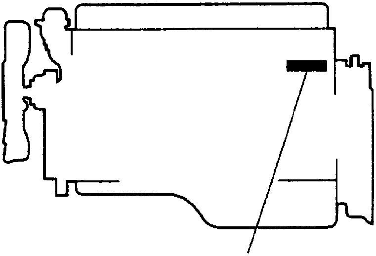
ENGINE NUMBER
• Serial engine numbers are assigned to the engines in manufacturing sequence. Every engine has its own number. These numbers are required for registration and related inspection of the vehicle.
• An engine nameplate indicates the following item.
• Engine model
PRECAUTIONS FOR MAINTENANCE OPERATION
• Before performing service operations, inquire into the customer ’s complaints and ascertain the conditions by checking the total distance traveled, the conditions under which the vehicle is operated, and other relevant factors about the vehicle. And note the necessary information. This information will help you to service the truck efficiently.
• Check the location of the fault, and identify its cause. Based on your findings, determine whether parts must be removed or disassembled. Then, follow the service procedure given in this manual.
• Prepare all the general and special tools necessary for the job.
WARNING
• Special tools must be used wherever specified in this manual. Do not attempt to use other tools since they could cause injuries and/or truck damage.
• Take extreme care when removing/installing heavy items such as engine, transmission and axle. When lifting heavy items using a cable etc., observe the following precautions.
• Identify the weight of the item being lifted. Use a cable that is strong enough to support the weight.
• If lifting eyes are not provided on the item being lifted, tie a cable around the item taking into account the item’s center of gravity.
• Never work in shoes that have oily soles. When working with a partner or in a group, use pre-arranged signals and pay constant attention to safety. Be careful not to touch switches and levers unintentionally.
• Inspect for oil leakage etc. before washing the vehicle. If the order is reversed, any oil leakage or fault that may exist could go unnoticed during inspection.
• Prepare replacement parts ready for installation.
• Oil seals, packings, O-rings and other rubber parts, gaskets, and split pins must be replaced with new ones after removal. Use only genuine MITSUBISHI replacement parts.
• When disassembling parts, visually check them for wear, cracks, damage, deformation, deterioration, rust, corrosion, defective rotation, fatigue, clogging and any other possible defect.
• To facilitate correct reassembly of parts, make alignment marks on them before disassembly and arrange disassembled parts neatly. Make punch marks and other alignment marks where they will not detract from parts’ functionality and appearance.
• After removing parts from the vehicle, cover the area to keep it free of dust.
CAUTION
•Be careful not to mix up identical parts, similar parts and parts that have left/right alignments.
•Keep new replacement parts and original (removed) parts separately.
• Apply the specified oil or grease to U-seals, oil seals, dust seals and bearings before reassembly.
• Always use the specified oils and greases when performing inspection or replacement. Immediately wipe away any excess oil or grease with a rag.
PRECAUTIONS FOR MAINTENANCE OPERATION
• Wear safety goggles when using a grinder or welder. Wear gloves when necessary, and watch out for sharp edges and other items that might wound your hands.
• Before working on the electrical system, disconnect the (–) battery cable to prevent short circuits.
CAUTION
•Make sure the starter switch and lighting switches are OFF before disconnecting or connecting battery cable. Semiconductor components may otherwise be damaged.
• Carefully handle sensors relays, and other items that are sensitive to shock and heat. Do not remove or paint the cover of any control unit.
• When separating connectors, grasp the connectors themselves rather than the harnesses.
• To separate locking connectors, first push them in the direction of the arrows. To reconnect locking connectors, push them together until they click.
• Before washing the vehicle, cover electrical parts to keep them dry. (Use plastic sheets or the like.) Keep water away from harness connectors and sensors and immediately wipe off any water that gets on them.
• When applying a voltage to a part for inspection purposes, check that the (+) and (–) cables are connected properly then gradually increase the voltage from zero. Do not exceed the specified voltage.
Remember that control units and sensors do not necessarily operate on the battery voltage.
1.Handling Precautions for Electric Circuits
CAUTION
•Do not pierce wire insulation with test probes or alligator clips when performing electrical inspections. Piercing the wire harness will cause corrosion.
1.1Inspection of harnesses
(1)Inspections with connectors fitted together (1.1)Waterproof connectors
• Connect an inspection harness and connector A between the connectors B of the circuit to be inspected. Perform the inspection by applying a test probe C to the connectors of the inspection harness. Do not insert the test probe C into the wire-entry sides of the waterproof connectors since this would damage their waterproof seals and lead to rust.
(1.2)Non-waterproof connectors
• Perform the inspection by inserting a test probe C into the wireentry sides of the connectors. An extra-narrow probe is required for control unit connectors, which are smaller than other types of connector. Do not force a regular-size probe into control unit connectors since this would cause damage.
(2)Inspections with connectors separated (2.1)Inspections on female terminals
• Perform the inspection by carefully inserting a test probe into the terminals. Do not force the test probe into the terminals since this could deform them and cause poor connections.
PRECAUTIONS FOR MAINTENANCE OPERATION
(2.2)Inspections on male terminals
• Perform the inspection by applying test probes directly to the pins.
CAUTION
•Be careful not to short-circuit pins together with the test probes. With control unit connectors, short-circuiting of pins can cause damage to the control unit’s internal circuitry.
• When using a multimeter to check continuity, do not allow the test probes to touch the wrong terminals.
1.2Inspection of connectors
(1)Visual inspection
• Check that the connectors are fitted together securely.
• Check whether wires have been separated from their terminals due to pulling of the harness.
• Check that male and female terminals fit together tightly.
• Check for defective connections caused by loose terminals, by rust on terminals, or by contamination of terminals by foreign substances.
(2)Checking
for loose terminals
• If connector terminal retainers become damaged, male and female terminals may not mate with each other when the connector bodies are fitted together. To check for such terminals, gently pull each wire and see whether any terminals slip out of their connector housings.
1.3Inspections when a fuse blows
• Remove the fuse, then measure the resistance between ground and the fuse’s load side.
Next, close the switch of each circuit connected to the fuse. If the resistance measurement between any switch and ground is zero, there is a short circuit between the switch and the load. If the resistance measurement is not zero, the circuit is not currently short-circuited; the fuse probably blew due to a momentary short circuit.
• The main causes of short circuits are as follows:
• Harnesses trapped between chassis parts
• Harness insulation damage due to friction or heat
• Moisture in connectors or circuitry
• Human error (accidental short-circuiting of components)
2.Service Precautions for Alternators
• When servicing alternators, observe the following precautions:
• Never reverse the polarity of battery connections. If the polarity of the battery connections were to be reversed, a large current would flow from the battery to the alternator, damaging the diodes and regulator.
PRECAUTIONS FOR MAINTENANCE OPERATION
• Never disconnect the battery cables with the engine running. Disconnection of the battery cables during engine operation would cause a surge voltage, leading to deterioration of the diodes and regulator.
• Never perform inspections using a high-voltage multimeter. The use of a high-voltage multimeter could damage the diodes and regulator.
• Keep alternators dry.
Water on alternators can cause internal short circuits and damage.
• Never operate an alternator with the B and L terminals short-circuited. Operation with the B and L terminals connected together would damage the diode trio.
• Disconnect the battery cables before quick-charging the battery with a quick charger.
Unless the battery cables are disconnected, quick-charging can damage the diodes and regulator.
3.Intermittent Faults
• An intermittent fault typically occurs only under certain operating conditions. Once these conditions have been identified, the cause of the intermittent fault can be ascertained easily. First, ask the customer about the vehicle operating conditions and weather conditions under which the fault occurs. Also ask about the frequency with which the fault occurs and about the fault symptoms. Then, reproduce the fault based on this information. In accordance with the conditions under which the fault occurs, determine whether the fault is caused by vibration, heat or other factors. if vibration is a possible factor, see if the fault can be reproduced by performing the following checks on individual connectors and other parts:
• Gently move connectors up and down and to left and right.
• Gently move wiring harnesses up and down and to left and right.
• Gently wiggle sensors and other devices by hand.
• Gently wiggle wiring harnesses on suspension systems and other moving parts.
• Connectors and other parts to be checked are those included or given as likely fault locations in inspection procedures corresponding to diagnostic codes and/or fault symptoms.
PRECAUTIONS FOR MAINTENANCE OPERATION
4.Precautions for Arc Welding
• When arc welding is performed, current from the welder flows to ground via the machine metal parts. Unless appropriate steps are taken, this current can damage control units, other electrical devices and wiring harnesses. And any electrical device near the point on the vehicle to which the (–) cable of the welder is connected, might be largely damaged.
• The current of the welder will flow backward through the battery’s (–) cable and damage the battery and electrical systems directly connected to the battery. Be sure to disconnect the battery’s (–) cable in the following procedure.
• Turn the battery switch to the LOCK position.
• Turn the starter switch to the LOCK position.
• Disconnect the battery’s (–) cable.
• Cover all parts of the machine that may be damaged by welding sparks.
• Connect the welder’s (–) cable to the machine as close as possible to the area being welded.
• Set the welding current in accordance with the part being welded.
DIAGNOSTIC CODES
NOTE:
The Multi-Use tester tool will not be used to service the 6M60-TL diesel engine at this time. Please disregard the Multi-Use Tester information. The Up-Time 2.41 or later software must be used to service the 6M60-TL diesel engine.
1.Using Multi-Use Tester
1.1Connecting Multi-Use Tester Special tools
V.C.I.
Multi-Use Tester harness A
Multi-Use Tester test harness D (used for extension)
USB cable
FMSi-E06-1 (Multi-Use Tester-III version)
N/A
Data transmission to/from V.C.I.
Data transmission between electronic control unit and PC
MH062928 Power supply to V.C.I. and communication with electronic control unit
MH062931 (1 m)
MH062951 (2 m)
Multi-Use Tester test harness A extension
MB991827 Communication between V.C.I. and PC
• Move the starter switch to the LOCK position.
• Connect , , and as illustrated.
• Connect the Multi-Use Tester connector on the vehicle with the connector of .
DIAGNOSTIC CODES
• Use to extend the cable if is not long enough such as when using Multi-Use Tester outside the vehicle.
1.2Access and Clearing of Stored Diagnostic Code
(1)Difference of diagnostic code
• There are two types of diagnostic codes – present code and past code.
(1.1)
(1.2)Present diagnostic code
• Fault developed in the machine after the starter switch is set to ON is indicated by corresponding diagnostic code.
• The fault warning lamp is lit at the same time.
(1.3)Past diagnostic code
• Past fault developed in the machine is indicated by corresponding diagnostic code stored in the memory of the electronic control unit.
• With the machine restored to its normal condition or the starter switch turned from OFF to ON after inspection or repair against present diagnostic codes, the present diagnostic code is stored as past diagnostic codes in the memory of the electronic control unit.
• The warning lamp is not lit because the indicated fault is not present one.
(2)Access of diagnostic code
• Set the starter switch to ON.
• Operate the Multi-Use Tester for a display of necessary diagnostic codes stored in the memory of the electronic control unit and identify the location of the fault.
(3)Clearing of diagnostic code
• Set the starter switch to ON (the engine not to be started).
• Operate the Multi-Use Tester to delete all the diagnostic codes stored in the memory of the electronic control unit.
2.Use of Blinking Warning Lamp for Diagnostic Code
• Using the diagnostic and memory clear switches, display diagnostic codes.
CAUTION
•Opening the memory clear switch followed by its reconnection will erase the stored diagnostic codes from the memory. To avoid inadvertently erasing necessary codes, be sure to read well the procedure described below before handling diagnostic codes.
2.1Reading diagnostic codes
• To read a diagnostic code, observe how may times the warning lamp flashes and how long each illumination lasts.
• The duration of illumination differs between the first and second digits.
• Second digit: 1.2 sec.
• First digit: 0.4 sec.
• A diagnostic code consists of the flashing of second digit and the flashing of first digit in that order. If a diagnostic code has “0” in the second digit, only the first digit will be displayed.
• The same diagnostic code will be displayed 3 times in a row before moving to the display of the next code.
• After the last diagnostic code is displayed, the first code will be displayed again 3 times in a row and then the subsequent codes. This will be repeated.
2.2Present diagnostic codes
• Turn the starter switch ON.
• Remove the diagnostic switch.
• Diagnostic codes will be displayed (flashing of the warning lamp).
• When the diagnostic switch is connected, electronic control unit will immediately stop (terminate) displaying diagnostic codes.
2.3Present and past diagnostic codes
• Turn the starter switch to the ON position.
• Open the diagnostic switch.
• Open the memory clear switch.
• The corresponding warning lamp will display diagnostic codes by flashing.
• Turn the starter switch to the OFF position, connect the memory clear switch and then connect the diagnostic switch. The electronic control unit terminates (exits) the diagnostic code displaying mode.
DIAGNOSTIC CODES
2.4Erasing diagnostic codes
• Turn the starter switch to the ON position (do not start the engine).
• Open the memory clear switch and reconnect it; all diagnostic codes stored in electronic control unit memory will be erased. To erase diagnostic code after opening the memory clear switch, turn the starter switch to the OFF position and then reconnect the memory clear switch.
TABLE OF STANDARD TIGHTENING TORQUES
3.Up-Time Service Tool Functions
3.1Menu
Monitor menu
• Input Monitor Indicates the input values of the controllers.
• Output Monitor Indicates the output values of the controllers.
• Custom Monitor Indicates the input/output values of the item selected.
• Fault Status Indicates all error codes occurring.
• Fault History Indicates the fault data, such as the error codes and hour meter data, stored in the controller.
Tool menu
• Set-up Option Indicates or sets the Setup Option data.
• Oscilloscope Graphs the input/output values. The oscillograph can be stored as data.
• Active Test Outputs the signal forcibly to check the operation of the equipment selected.
• Connection Change Designates the controller operated by the service tool and the controller connected to it.
• Firmware Update Updates the firmware of the controller connected.
TABLE OF STANDARD TIGHTENING TORQUES
3.2Input Monitor and Output Monitor
These screens indicate the input and output values of each controller.
3.2.1VCM-3 input monitor and output monitor (VCM-3 → VCM-3)
(InputUnit)
3.2.2VCM-3OP
212342
3.3Fault Status
This screen indicates all error codes occurring.
212344
3.4Fault History
This screen indicates the fault data, such as the error codes and hour meter data, stored in the controller. 2123
InputUnit
OutputUnit
InputUnit
OutputUnit
InputUnit
OutputUnit
InputUnit
4.Troubleshooting
4.1General Information
4.1.1Before replacing controllers
Do not replace controllers casually even if replacement is required as a result of troubleshooting. Be sure to check the following items before replacing controllers.
• Loose battery connectors
• Abnormal wire harness connections
• Loose connectors
• Broken, bent or loose connector pins
• Dirty connectors
If connectors are dirty, remove the connector and clean connectors. See “How to clean harness connectors and system components” on the next page.
• Ensure that the main harness is not short-circuited to the truck body.
If any of these items (above items) is a source of the trouble, the controller will be damaged even if it is replaced with a new one. Be sure to check the above items and replace carefully.
4.1.2Connection of service tool
(1)Turn off the truck power.
(2)Find the service tool connector in the CAB harness.
(3)Remove the cover and connect the PC as shown.
(4)Turn on the truck power.
(5)Start the service tool software.
4.1.3Diagnostic Precautions
(1)Before measuring voltage, check the battery for charged condition and specific gravity. If system inspection is performed with the battery uncharged or reduced in specific gravity, accurate measurements cannot be achieved.
(2)To avoid having electrical parts damaged, set the starter switch to OFF before disconnecting and reconnecting battery cables.
(3)Before disconnecting connectors, set the starter switch to OFF then allow at least 20 seconds. Voltage may remain in electric parts or connected circuit.
(4)When performing measurement with the tester, handle the test bar carefully so that it does not damage internal circuit and other electrical parts of the electronic control unit to result in a short-circuit failure between terminals in connector or between connector and truck body.
(5)Resistance is affected by temperature. Determine the necessity of resistance measurement following given temperature specification as a guide. Otherwise, use normal temperature (10 to 35°C) as the measuring condition.
VCM-3OP
4.1.4How to clean harness connectors and system components
(1)Open-circuits are often caused by dirty harness connectors and components. Dust, together with greasy matter, forms grime which, in time, penetrates electrical connections, resulting in loose metal-to-metal contact or, for worse, electrical separation of surfaces in contact. For this reason, it is essential that the connectors and components be cleaned at each periodic inspection and when servicing the truck. Instead of a commonly used solvent, use the electronic parts cleaner (in the manner illustrated on the right).
Electronic parts cleaner Three Bond 29D or Pow-R-Wash CZ*
NOTE
•The cleaner liquid is volatile. All you have to do is just give a strong spray to wash off grime. No need to wipe off the sprayed liquid.
(2)After checking the connector for continuity, wash it as shown. Then, uncouple the connector and spray the contact surface activator onto contact surfaces.
Install and remove the connector several times to wet the surfaces thoroughly with the activator liquid.
After coupling up the connector, check to be sure that it is in locked state.
Contact surface activator Three Bond 2501S (aerosol) or Nyogel 760G*
*: Products contained in Terminal Maintenance kit (SE000003)
NOTE
•Do not spray too much liquid into the connector. Cleaner liquid reacts differently with some resins (plastic materials).
parts cleaner
Electronic parts cleaner
Contact surface activator
• Use specified bolts and nuts. Tighten them to the torques shown below as appropriate, unless otherwise specified.
• Threads and bearing surfaces shall be dry.
• If the mating nut and bolt (or stud bolt) are different in level of strength, tighten them to the torque specified for the bolt.
Hexagon Head Bolts and Stud Bolts (Unit: N·m {kgf·m})
Identification symbol
M5 2 to 3 {0.2 to 0.3}
M6 4 to 6 {0.4 to 0.6}
M8 9 to 13 {0.9 to 1.3}
M10 18 to 27 {1.8 to 2.7} 17 to 25 {1.8 to 2.6}
4 to 6 {0.4 to 0.6}
7 to 10 {0.7 to 1.0}
to 2.5}
to 50 {3.5 to 5.1}
to 4.9}
5 to 7 {0.5 to 0.7}
8 to 12 {0.8 to 1.2}
to 2.9}
to 6.0}
to 55 {3.8 to 5.7} M12 34 to 50 {3.4 to 5.1} 31 to 45 {3.1 to 4.6} 70 to 90 {7.0 to 9.5}
M14 60 to 80 {6.0 to 8.0} 55 to 75 {5.5 to 7.5} 110 to 150 {11 to 15}
M16 90 to 120 {9 to 12} 90 to 110 {9 to 11} 170 to 220 {17 to 23}
M18 130 to 170 {14 to 18} 120 to 150 {12 to 16} 250 to 330 {25 to 33}
M20
M22
M24
to 240 {19 to 25}
to 330 {25 to 33}
to 430 {33 to 44}
to 220 {17 to 22}
to 300 {23 to 30}
to
{29 to 39}
to
{35 to 47}
to
{47 to 63}
Hexagon Head Flange Bolts (Unit: N·m {kgf·m})
Identification symbol
Nominal diameter
M6
to
to 31 {2.1 to 3.1} 20 to 29
to 3.0}
to 85 {6.5 to 8.5}
to 140 {11 to 14}
to 210 {16 to 21}
to 290 {23 to 30}
to
{32 to 42}
to
{43 to 57}
to 105 {8.5 to 11} 75 to 95 {7.5 to 10}
to
{13 to 17}
to
{20 to 27}
{30 to 39}
to
{41 to 55}
to
{55 to 73}
to 160 {12 to 16}
to 240 {19 to 25}
to 340 {26 to 35}
to 480 {37 to 49}
to
{50 to 67}
to 3.3}
to 120 {9 to 12}
to 110 {8.5 to 11}
Hexagon Nuts (Unit: N·m {kgf·m})
Strength 4T 6T
Identification symbol
M5 2 to 3
{0.2 to 0.3} –4 to 6 {0.4 to 0.6}
M6 4 to 6 {0.4 to 0.6} –7 to 10 {0.7 to 1.0} –
M8 9 to 13 {0.9 to 1.3} –16 to 24 {1.7 to 2.5} –
M10 18 to 27 {1.8 to 2.7} 17 to 25 {1.8 to 2.6} 34 to 50 {3.5 to 5.1} 32 to 48 {3.3 to 4.9}
M12 34 to 50 {3.4 to 5.1} 31 to 45 {3.1 to 4.6}
to 90 {7.0 to 9.5}
to 85 {6.5 to 8.5}
M14 60 to 80 {6.0 to 8.0} 55 to 75 {5.5 to 7.5} 110 to 150 {11 to 15} 100 to 140 {11 to 14}
M16 90 to 120 {9 to 12} 90 to 110 {9 to 11} 170 to 220 {17 to 23} 160 to 210 {16 to 21}
M18 130 to 170 {14 to 18} 120 to 150 {12 to 16} 250 to 330 {25 to 33}
M20 180 to 240 {19 to 25} 170 to 220 {17 to 22}
M22 250 to 330 {25 to 33} 230 to 300 {23 to 30}
M24
320 to 430 {33 to 44} 290 to 380 {29 to 39}
Hexagon Flange Nuts (Unit: N·m {kgf·m})
Strength 4T
Identification symbol
Nominal diameter Standard screw thread Coarse screw thread
M6 4 to 6 {0.4 to 0.6} –
M8 10 to 15 {1.0 to 1.5} –
M10 21 to 31 {2.1 to 3.1} 20 to 29 {2.0 to 3.0}
M12 38 to 56 {3.8 to 5.6} 35 to 51 {3.5 to 5.2}
340 to 460 {35 to 47}
460 to 620 {47 to 63}
600 to 810 {62 to 83}
220 to 290 {23 to 30}
310 to 410 {32 to 42}
420 to 560 {43 to 57}
540 to 720 {55 to 73}
Tightening Torque for General-Purpose Flare Nut (Unit: N·m {kgf·m})
Tightening Torque for General-Purpose Air Piping Nylon Tube (DIN Type) (Unit: N·m {kgf·m})
Tightening Torque for General-Purpose Air Piping Nylon Tube (SAE Type) (Unit: N·m {kgf·m})
GROUP 11 ENGINE
Specifications
Engine mode 6M60
Type 6-cylinder, in-line, water-cooled, 4-cycle diesel engine
Combustion chamber Direct injection type
Valve mechanism Overhead camshaft (OHC) system
STRUCTURE AND OPERATION
1.Engine Proper
• The 6M60-TL engine employs an overhead camshaft (OHC) system, with the valve mechanism and the timing gears arranged as shown above.
2.Rocker and Bracket Assembly, Camshaft, Rocker Case and Cylinder Head Gasket
• The camshaft is directly supported at its journals by the rocker case, and is held in place from above by the rocker and bracket assembly.
• The camshaft journals are directly supported by the rocker case and the rocker and bracket assembly, without using any camshaft bearings. The rocker case and brackets have been machined together, meaning that they all need to be replaced with a new set when one of them becomes defective.
3.Valve Mechanism
• Each valve has a valve stem seal, which regulates the flow of lubricating oil to the contact surface between the valve and the valve guide.
• The valve springs have a variable pitch to prevent abnormal vibration at high engine speed. The exhaust valves use a double spring, with the inner and outer springs coiled in different directions to prevent them from jamming each other.
5. Piston
• The piston, the cylinder liner and the crankcase bore all must have the same size marks to ensure a good fit between them.
• The pistons are made of special aluminum alloy, and are provided with a recess on each end of the piston pin boss to reduce weight.
STRUCTURE AND OPERATION
6. Timing Gears
• The timing gears are provided with timing marks to help ensure correct assembly.
• Timing marks are provided on the following gears.
• Camshaft gear: stamped line
• Crankshaft gear: “1”
• Air compressor gear: “2”
• No. 1 idler gear: “1”, “2”
6.1 No. 3 idler gear
• The No. 3 idler gear consists of the sub-gear A, the sub-gear B and the main gear.
• A spring is installed between the subgear A and the main gear, as well as between the sub-gear B and the main gear. The springs are locked in place with pins.
• The sub-gears are installed as follows. The sub-gear A has been turned in such a way as to compress the spring before meshing with the camshaft gear. Likewise, the sub-gear B has been turned to compress the spring before meshing with the No. 2 idler gear.
(1)Non-backlash mechanism
• Engine hunting during idling causes fluctuation in the speed of camshaft and No. 2 idler gears.
• Without the non-backlash mechanism, the backlash changes between zero and the maximum, generating gear rattle noise.
• With the non-backlash mechanism equipped on the engine, the sub-gears A and B maintain the backlash to zero even when the engine hunts, eliminating gear rattle during idling.
7. Flywheel
TROUBLESHOOTING
Possible causes
Cylinder head and valve mechanism
Timing gears
Camshaft
Pistons and connecting rods
Incorrect valve clearanceOO
Defective cylinder head gasketOO
Worn valve and valve seat; carbon depositsOO
Weakened valve springOO
Defective rocker shaft and bracketO
Poor lubrication of rocker shaft bracketO
Incorrect backlash in timing gearsO
Poor lubrication of timing gears and idler shaftO
Excessive end play in camshaftO
Worn camshaftO
Worn/damaged piston ring groove(s)OO
Worn/damaged piston ring(s)OO
Worn piston pin and connecting rod small endO
Excessive end play in crankshaftO
Incorrectly fitted crankshaft pulleyO
Crankshaft
Fuel system
Cooling system
Intake and exhaust system
Worn/damaged crankshaft pins and connecting rod bearings O
Worn/damaged crankshaft journals and main bearingsO
Supply pump faultyOO Gr13E
Defective injectorOO
Air trapped in fuel systemOGr13A
Malfunctioning cooling system componentsO Gr14
Loose/damaged V-beltsO
Clogged air cleanerOO Gr15
Clogged mufflerOO
Malfunctioning turbochargersOO
Incorrect oil viscosityOGr12
Improper fuel O
Incorrectly fitted piping and hosesO
Defective/incorrectly fitted alternator and other auxiliariesO
GENERAL INSPECTION AND ADJUSTMENT
1. Measuring Compression Pressure Service standards
• A drop in compression pressure can be used as a guide to determine when the engine should be overhauled.
• Measure the compression pressure at regular intervals. Keeping track of its transitions can provide a useful tool for troubleshooting. On new vehicles and vehicles with newly replaced parts, the compression pressure will be somewhat higher depending on the break-in condition of piston rings, valve seats, etc., but this will return to normal as the parts wear down.
• Before inspection, confirm that the engine oil, starter, and battery are in normal condition, and satisfy the following conditions.
• Warm up the engine until the coolant temperature reaches approximately 75 to 85°C.
• Turn off the lights and auxiliaries.
• Place the lever in neutral.
• Remove the fuse for fuel cut to prevent fuel from being injected while the engine is cranked using the starter.
CAUTION
•When cranking the engine, never shut off the power supplied to the engine electronic control unit by disconnecting the engine electronic control unit connector or other similar methods. If the engine is cranked with the power to the engine electronic control unit shut off, the supply pump will not be controlled by the electronic control unit, causing the supply pump to be malfunctioned.
• Remove all the injectors. (See Gr13A.)
• Cover the injector mounting holes with shop towels or other similar cloth. Crank the engine using the starter. Ensure that no foreign matter is attached on the shop towels.
CAUTION
•If cracks or any other damage are evident in the cylinders, this means that the coolant, engine oil or fuel, or other substances, has entered the cylinders. If this is the case, it is extremely dangerous to crank the engine as these substances will gush out at high temperature from the injector mounting holes. Stay away from the engine when cranking it.
• Attach the nozzle gasket and to one of the injection nozzle mounting holes. Then, connect a compression gauge to .
• Crank the engine and measure the compression pressure.
• Measure the compression pressure for all the cylinders one after another. Determine the compression pressure difference between the cylinders.
• If the compression pressure is below the limit or the cylinder-tocylinder pressure differences is not within the limit, pour a small amount of engine oil into the corresponding injection nozzle mounting hole and remeasure the compression pressure.
• If the compression pressure increases, the piston rings and cylinder surfaces may be badly worn or otherwise damaged.
• If the compression pressure remains unchanged, there may be seizure in the valves, the valves may be incorrectly seated or the cylinder head gasket may be defective.
• Install the injectors. (See Gr13A.)
• Install the rocker cover and gasket. (See later pages.)
GENERAL INSPECTION AND ADJUSTMENT
2. Inspection and Adjustment of
Service standards (Unit: mm)
Valve Clearances
Tightening torque (Unit: N m {kgf m})
Mark Parts to be tightened Tightening torque Remarks
–Lock nut (adjusting screw tightening)
–Lock nut (rocker arm adjusting screw tightening)
Special tools
59 {6.0} –
34 {3.5} –
Mark Tool name and shape Part No. Application
the lock nut
• Valve clearances should be checked and adjusted as follows while the engine is still cold.
[Inspection]
• Remove the rocker cover.
• Bring the No. 1 or No. 6 cylinder piston to the top dead center (TDC) on the compression stroke according to the following procedure:
• Rotate the crankshaft until the pointer is aligned with the “1 6” mark on the flywheel.
• This will place either the No. 1 or No. 6 cylinder piston at TDC on the compression stroke. The cylinder in which the rocker arms for both the intake and exhaust valves can be pushed down by hand by the valve clearance amounts has its piston at TDC. Rotate the engine by one full turn to switch the TDCs of the No. 1 and No. 6 cylinder pistons.
• With the No. 1 or No. 6 cylinder piston at TDC, measure the clearance of the valves (clearance between valve bridge and pad) marked with a circle in the table below.
No. 1 cylinder piston at TDC on compression stroke
No. 6 cylinder piston at TDC on compression stroke
Socket wrench
Mitsubishi 6M60 Engine Parts
• Any attempt to insert a feeler gauge without first securing sufficient space, as described below, between the pad and the valve bridge will fail, as the pad will tilt as shown in the illustration, thus blocking the entry of a feeler gauge.
• Before inserting a feeler gauge, push the adjusting screw pad on the side opposite from where a feeler gauge is to be inserted, as shown in the illustration, using a flat-head screwdriver or other similar tool. This will create space necessary for the gauge to be inserted.
• The measurement is correct when the feeler gauge feels slightly resisted as it is inserted.
• The measurement is not yet correct if the feeler gauge can still be inserted smoothly.
• If the measurement deviates from the standard value, adjust as follows.
[Adjustment]
• Loosen the lock nuts and adjusting screws on the valve bridge and rocker arm.
• While holding the valve bridge by hand, screw in the adjusting screw until it lightly contacts the valve stem end.
• Then, further screw in the adjusting screw by 45° .
• While holding the adjusting screw in this position with a socket wrench and extension, tighten the lock nut to the specified torque using .
CAUTION
•After adjusting the adjusting screw, be sure to tighten the lock nut to the specified torque. Insufficient torquing will compromise the parallelism of the valve bridge, damaging the valve mechanism.
• Screw in or out the adjusting screw on the rocker arm until the correct feeler gauge can be inserted with a slight resistance.
• While holding the adjusting screw in this position with a screwdriver, tighten the lock nut to the specified torque using .
• Recheck the valve clearance using the correct feeler gauge.
[Installation]
• Install the rocker cover and gasket. (See later pages.)
ROCKER COVER, ROCKER BRACKET AND CAMSHAFT
Disassembly sequence
1 Oil filler cap
2 Rubber
3 Rocker cover
4 Rocker cover gasket
5 Baffle plate
6 Cylinder recognition sensor
7 Rocker case upper
CAUTION
8 Rocker case upper gasket
9 Packing
10 Rocker and bracket assembly (See later pages.)
11 Camshaft (See later pages.)
12 Rocker case
13 Rocker case gasket
*a:Cylinder head
*b:No. 3 idler gear
:Locating pin
:Non-reusable parts
•The rocker case and the brackets of the rocker and bracket assembly have been machined together, which means that they all must be replaced together. Never swap the locations of the brackets, either.
Assembly sequence
Follow the disassembly sequence in reverse.
Service standards (Unit: mm)
Location Maintenance item
–Camshaft end play 0.05 to 0.20 0.4 Inspect 11, *bBacklash between camshaft gear and No. 3 idler gear0.18 to 0.26 0.35Replace
Tightening torque (Unit: N m {kgf m})
Mark Parts to be tightened
Remarks Bolt (rocker cover mounting) 8.8 {0.9} –
Lubricant and/or sealant
Mark
Points of application Specified
Rubber portion of oil filler cap
Camshaft journal supports on rocker and bracket assembly
Camshaft journals and cams
Camshaft journal supports on rocker case
Periphery and top surface of packing
Work before removal
1217H As required
Inspection: Backlash between camshaft gear and No. 3 idler gear
• Measure the backlash at least at three different locations. If the measurement exceeds the limit, replace the defective part(s).
ROCKER COVER, ROCKER BRACKET AND CAMSHAFT
Inspection: Camshaft end play
• If the measurement exceeds the limit, replace the defective part(s).
Removal procedure
Releasing valve spring force
• Before loosening the rocker and bracket assembly mounting bolts, check whether the valve springs are compressed by the rockers. If so, loosen the adjusting screws on the rockers to relieve the spring force. This will eliminate the possibility of compressed springs damaging parts when they are released.
Removal: Camshaft
• Remove the plug at the rear end of the cylinder head.
• Insert a sub-gear locking bolt (M8 × 1.25 mm, length 20 mm) into the dedicated hole in the No. 3 idler gear to lock the subgears. Remove the camshaft.
Installation procedure
Installation: Rocker case
• Tighten the rocker case bolts in the order shown in the illustration.
Installation: Camshaft
• Make sure that the timing marks on the timing gears are aligned with each other.
• Install the camshaft so that the stamped line on the camshaft gear is level with the top surface of the rocker case.
• Install the plug at the rear end of the cylinder head. (See later pages.)
Mitsubishi 6M60 Engine Parts
Installation: Packing
• Apply sealant onto the peripheral surface of the packing.
• Immediately after the sealant application, install the packing to the rocker case.
• After installing it on the rocker case, apply sealant to the top surface of the packing.
• Immediately after the sealant application, install the rocker case upper and rocker case upper gasket in place.
CAUTION
•Do not start the engine for one hour after installation. •When removing the rocker cover after installation, never fail to apply sealant again.
Installation: Rocker case upper gasket
• Make sure that the gasket fitting groove in the rocker case is clear of grease and dirt. Clean if necessary.
• Before installation, make sure that the gasket is free of grease, etc. that could cause an oil leakage.
Installation: Rocker cover gasket
• Make sure that the gasket fitting groove in the rocker cover is clear of grease and dirt. Clean if necessary.
• Before installation, make sure that the gasket is free of grease, etc. that could cause an oil leakage.
•After the No. 3 idler gear has been reassembled onto the cylinder head, remove the locking bolt from the sub-gears.
Service standards (Unit: mm)
Location
–
13, 18
Backlash between No. 3 and No. 2 idler gears 0.17 to 0.25 0.35Replace No. 3 idler gear end play 0.05 to 0.15 0.3Replace
Clearance between No. 3 idler shaft and No. 3 idler gear bushing 0.01 to 0.05 0.2Replace
Tightening torque (Unit: N m {kgf m})
Mark
Parts to be tightened
Nut (connecting plate mounting) 1.0 to 1.5 {0.1 to 0.15}
(nozzle bridge mounting)
Cylinder head bolt
{8} + 90
to 3 times
Plug 13 to 17 {1.3 to 1.7} –Nut (collar mounting) 39 to 59 {4.0 to 6.0}
3 idler bolt
Lubricant and/or sealant
Threaded portion of cylinder head bolt
O-ring
Threaded portion of No. 3 idler bolt
Periphery of No. 3 idler shaft
Inside surface of No. 3 idler gear bushing
Top mating surfaces of flywheel housing and crankcase
Mitsubishi 6M60 Engine Parts
Contact email:
Phone: 269 673 1638 www.6M60.com
1207F As required
CYLINDER HEAD AND VALVE MECHANISM
Special tools (Unit: mm)
Mark Tool name and shape
Socket wrench
Pin wrench arm
Idler gear push-puller
Work before removal
Part No. Application
MH063388Installation of cylinder head
MH063473Assembly of No. 3 idler gear
MH061779 Removal and installation of No. 3 idler gear bushing
Locking sub-gears
• Before removing the No. 3 idler gear, install a locking bolt (M8 × 1.25 mm, length 20 mm) into the dedicated hole to lock the subgears.
Inspection: End play of No. 3 idler gear
• If the measurement exceeds the limit, replace the defective part(s).
Inspection: Backlash between No. 2 and No. 3 idler gears
• If the measurement exceeds the limit, replace the defective part(s).
Removal procedure
Removal: Cylinder head
• Remove the bolts (× 4).
• Progressively loosen the cylinder head bolts in the order shown in the illustration, going over them several times, before eventually removing them.
Inspection procedure
Removal: Cylinder head gasket CAUTION
•Be careful not to scratch the cylinder head, crankcase and flywheel housing when removing the cylinder head gasket.
Inspection: Clearance between No. 3 idler shaft and No. 3 idler gear bushing
• If the measurement exceeds the limit, replace the bushing.
Replacement of No. 3 idler gear bushing [Removal]
[Installation]
• Using, press in the bushing until contacts the No. 3 idler gear.
• After installation, measure the clearance again.
• If the measurement is lower than the standard value, ream the bushing.
CYLINDER HEAD AND VALVE MECHANISM
Installation procedure
Installation: Sub-gears
• Install the No. 3 idler gear on a vice. Use shop towel to protect the gear from direct contact with the vice.
• Install a sub-gear, a spring and pins on one side of the No. 3 idler gear.
• Hook each end A of the spring on a pin.
• Install a snap ring.
• Using , turn the sub-gear clockwise until the countermark on the sub-gear is aligned with the stamped line on the No. 3 idler gear. Then, install a locking bolt (M8 × 1.25 mm, 20 mm long) into the dedicated hole.
• Turn over the No. 3 idler gear and repeat the same procedure on the other side of the No. 3 idler gear, installing another sub-gear, a spring, pins and a snap ring.
Installation: Cylinder head CAUTION
•Before fitting the cylinder head bolts, check the punch marks on each bolt’s head. Do not use the bolt if there are three punch marks. The punch marks indicate the number of times each bolt has been tightened using the torque-turn tightening method. Any bolt that already has three punch marks must be replaced.
• The cylinder head gasket is a part that needs to be selected for use. Choose the appropriate gasket in the following manner.
• Measure the piston protrusion from each cylinder. (See Piston.)
• Then, from the table below, choose the cylinder head gasket having a thickness appropriate to the average protrusion of the pistons.
• If the cylinder head has even one cylinder that exceeds the largest of the measured piston protrusions by 0.05mm or more, use a gasket at least one size larger in thickness (A → B, B → C).
Piston protrusion
Average piston protrusion
0.804 to 0.872
0.873 to 0.941
0.942 to 1.011
Unit: mm
Cylinder head gasket
Type by size ( ): No. of notches
• Identify the appropriate type of cylinder head gasket according to the number of notches in its notched end.
• Remove oil and any other contamination from the surfaces where sealant is to be applied.
• Apply sealant onto the surfaces of the flywheel housing and crankcase that will be fitted together.
• Within three minutes following the sealant application, install the cylinder head onto the crankcase, with the cylinder head gasket in between them, using the cylinder head bolts. Take care so that the applied sealant is not displaced during installation. Be sure to install the gasket in the illustrated position.
CAUTION
•Do not start the engine for at least an hour after installation. •Whenever cylinder head bolts are loosened or removed after installation, the cylinder head gasket must be replaced and sealant reapplied.
• Tighten the cylinder head bolts to a torque of 78N.m {8kgf.m} in the order shown in the illustration.
• Further tighten the bolts in the illustrated order as follows.
CYLINDER HEAD AND VALVE MECHANISM
• Turn the holder of counterclockwise to pretension the internal spring.
• Set the tool such that the rod (extension) is pressed against the rocker shaft bracket by the force of the spring.
• Align any line on the holder scale with any line on the socket scale. (This will be used as the reference point = 0°.)
• From the reference point, turn the socket by 90° in the direction shown. Each division on the holder scale represents 5°
• Further turn the socket by 90° .
+5° 0 +5° 0
• After tightening the cylinder head bolts within the plastic region, punch a mark on the bolt heads to record the number of times that they have been tightened.
CAUTION
•Cylinder head bolts that have been tightened using the torque-turn method must never be additionally tightened after the final angular tightening.
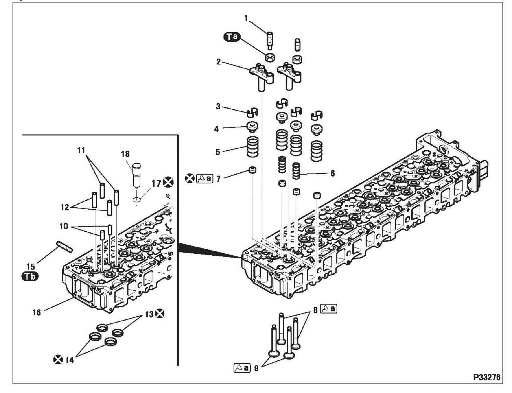
CYLINDER HEAD, INJECTOR TUBES AND VALVE MECHANISM
Mitsubishi 6M60 Cylinder Head Disassembly
Follow the disassembly sequence in reverse.
Service standards (Unit: mm)
Tightening
torque (Unit: N·m {kgf·m})
Lubricant and/or sealant
CYLINDER HEAD AND VALVE MECHANISM
Special tools (Unit: mm)
Mark Tool name and shape
Valve lifter
Valve lifter hook
Valve lifter seat A
φ 38
Valve stem seal installer AB
25 φ 9
Valve lapper
Valve bridge guide installer AB
1037.2
Valve guide remover
8 φ 12
Valve guide installer
25.5 φ 1317
Caulking tool body
Part No. Application
MH061668
MH061679
MH061772
Installer ring
Removal and installation of valve cotters
MH062689Installation of valve stem seals
30091-07500Lapping valves and valve seats
MH062724Installation of valve bridge guides
31391-10500Removal of valve guides
MH062726Installation of valve guides
31391-13100
MH062725 <Intake valve>
MH063605 <Exhaust valve>
Installation of valve seat
Special tools (Unit: mm)
Injector tube remover
Injector tube installer bolt
Injector tube installer body
Injector tube sizing tool
Removal procedure
MH998004
MH907553
Removal of Mitsubishi 6M60 injector tube
MH907601
MH907781
Installation of 60 nozzle tube
Removal: Injector tube
CYLINDER HEAD AND VALVE MECHANISM
Installation procedure
Installation: M60 Injector tubes
• Apply a sealant to the perimeter A of the tip of the injector tube.
• Push in the injector tube by hand until it contacts surface B of the cylinder head.
• Tighten with the bolt and press the injector tube onto surface B of the cylinder head.
• Apply engine oil to section C of.
• Screw in until can be pulled out from the bottom of the cylinder head.
• After installing the injector tube, be sure to perform a leak test to check for airtightness.
Removal procedure
Removal: Valve cotters
• Using , and , remove the valve cotter while compressing the valve spring(s) evenly.
Inspection procedure
Inspection: Valve bridge and valve bridge guide
(1)Valve bridge-to-guide clearance
• If the measurement exceeds the limit, replace the defective part(s).
(2)Outside diameter of valve bridge guide
• If the measurement is less than the limit or the valve bridge guide is worn extremely unevenly, replace the valve bridge guide.
Replacement of valve bridge guide [Installation]
• Before installation, ensure that no water, oil or other foreign matter is in the installation hole.
• Using, install the valve bridge guide until comes into positive contact with the cylinder head.
CAUTION
•The valve bridge guide must be installed to the specified depth of the cylinder head. Correct installation can only be possible by using .
Inspection: Intake and exhaust valve
(1)Valve stem outside diameter
• Replace the valve if the stem’s outside diameter is below the limit or is severely worn.
• When the valve has been replaced with a new one, make sure to lap the valve and valve seat.
(2)Valve seat angle and valve margin
• Reface or replace the valve if the valve seat angle or valve margin exceeds the specified limits.
• After refacing or replacing the valve seat, make sure to lap the valve and valve seat.
CYLINDER HEAD AND VALVE MECHANISM
Refacing
• Limit grinding to a necessary minimum.
• If the valve margin is below the limit after grinding, replace the valve.
• After grinding, make sure to lap the valve and valve seat.
Inspection: Valve-to-valve guide clearance
• If the clearance exceeds the specified limit, replace the defective part(s).
Replacement of valve guides [Removal]
[Installation]
• Install the valve guide until sits snugly on the cylinder head.
CAUTION
•The valve guide must protrude from the cylinder head by the specified amount. Correct installation can only be possible by using .
•The valve guides for the exhaust valves are longer than the valve guides for the inlet valves.
Inspection: Contact between valve and valve seat
• Before starting inspection, check that the valve and valve guide are intact.
• Apply an even coat of red lead to the valve contact surface of the valve seat.
• Strike the valve once against the valve seat. Do not rotate the valve during this operation.
• If the red lead deposited on the valve indicates a poor contact pattern, take either of the following corrective actions.
Contact pattern Corrective action
Minor defectLapping
Serious defectReface or replace valve and valve seat
Lapping
• Lap the valve in the following sequence.
• Apply a thin coat of lapping compound to the seat contact surface of the valve. Adding a small amount of engine oil to the lapping compound can facilitate even application.
CAUTION
•Do not put any compound on the stem.
• Start with an intermediate-grit compound (120 to 150 grit) and finish with a fine-grit compound (200 grit or more).
• Strike the valve several times against the valve seat while rotating the valve a little at a time.
• Wash away the compound with diesel fuel.
• Apply engine oil to the valve contact surface of the valve seat and rub in the valve and seat well.
• Inspect the contact pattern of the valve and valve seat again.
• If the contact pattern is still defective, replace the valve seat.
Inspection: Valve seats
(1)Valve seat width
• If the measurement exceeds the limit, reface or replace the valve seat.
• After refacing or replacing the valve seat, make sure to lap the valve seat and valve.
(2)Valve sinkage from cylinder head bottom surface
• Perform measurement keeping the valve in close contact with the valve seat.
• If the measurement exceeds the limit, adjust or replace the defective part(s).
• After refacing or replacing the valve seat, make sure to lap the valve seat and valve.
CYLINDER HEAD AND VALVE MECHANISM
Refacing the valve seat
• Grind the valve seat using a valve seat cutter or valve seat grinder.
• Place a piece of sandpaper of approximately #400 between the cutter and valve seat and grind the valve seat lightly.
• Use a 15° or 75° cutter to cut the valve seat to a width within the standard range.
CAUTION
•Make sure that the valve seat refacing does not cause the valve sinkage to exceed the specified limit.
• Lap the valve and valve seat.
Replacement of valve seat [Removal]
• The valve seats are installed by expansion fitting. To remove a valve seat, grind inside the metal stock to reduce the wall thickness, then remove the valve seat at room temperature.
[Installation]
• Check that the diameters of the valve seat holes in the cylinder head conform with the values shown below.
• Replace the cylinder head if necessary.
• Chill the valve seat thoroughly by immersing in it in liquid nitrogen.
• Install the valve seat in the cylinder head using and
• Lap the valve seat and valve.
Inspection: Cylinder head bottom surface distortion
• If the distortion exceeds the specified limit, rectify it using a surface grinder.
CAUTION
•Make sure that the height of the cylinder head from the top surface to the bottom surface is not reduced to a value below the specified limit.
Installation procedure
Installation: Valve stem seal
• Apply engine oil to the lip of the valve stem seal.
• Install the valve stem seal until sits snugly on the cylinder head.
CAUTION
•After installing the valve stem seal, check that its spring is not deformed or damaged.
Installation: Valve spring
• Install the outer and inner valve springs onto the cylinder head while facing them as shown in the illustration.
Installation: Valve cotter
• Using , and , install the valve cotter while compressing the valve spring(s) evenly.
CAUTION
•Do not compress the valve spring(s) too much, or the upper retainer will contact the valve stem seal and damage will result.
1 Lower connecting rod bearing 2 Connecting rod cap
3 Upper connecting rod bearing 4 Piston and connecting rod (See later sections.)
5 Cylinder liner :Locating pin
Assembly sequence
Follow the disassembly sequence in reverse.
Service standards (Unit: mm)
Location Maintenance item Standard
–Piston projection from crankcase top surface 0.81 to 1.01 – Inspect –Connecting rod end play 0.15 to 0.45 0.6 Inspect
1, 3Connecting rod bearing Oil clearance 0.034 to 0.093 0.2 Replace Span when free –Less than 74.5
4, 5Piston and connecting rod-to-cylinder liner clearance0.19 to 0.21 – Replace 5Cylinder liner Flange projection 0.03 to 0.10 –Replace Bore
Tightening torque (Unit: N m {kgf m})
Lubricant and/or sealant
Threaded portion of connecting rod bolt
Inside surface of connecting rod bearing Outside periphery of cylinder liner
Outside periphery of piston
Special tools (Unit: mm)
Mark Tool name and shape
Piston guide clamp
Piston guide lever
Socket wrench
Cylinder liner extractor
117.5
Cylinder liner installer
117.5
Inspection before removal
Part No. Application
MH061658
MH061760 Installation of piston and connecting rod
MH061560
MH061761Removal of cylinder liner
MH061771Installation of cylinder liner
Retaining cylinder liners
• The cylinder liners may move up when the crankcase is turned over, or the crankshaft is rotated after the pistons are installed. To prevent this, retain the cylinder liners by holding their flanges with bolts and washers.
PISTON AND CONNECTING ROD, CYLINDER LINER
Inspection: Piston projection from crankcase top surface CAUTION
•The amount of piston projection affects engine performance and must therefore be inspected without fail.
• Set the piston at the top dead center.
• Mark reference points A (seven points in total) on the top surface of the crankcase as shown in the illustration. Using each of the marks as a zero point, measure the amount of piston projection relative to the zero point (height of measurement point B –height of reference point A).
• Make the measurements at the two measurement points B for each cylinder (twelve points in total) using the reference point A nearest to each measurement point, and calculate the average value of all the measurements.
• If the average value is out of the standard value range, check the clearances between all relevant parts.
Inspection: Connecting rod end play
• Measure the end play for every connecting rod.
• If any measurement exceeds the specified limit, replace the defective part(s).
Inspection: Cylinder liner flange projection
• If the measurement deviates from the standard value, inspect the installation and replace the defective part(s).
CAUTION
•If the cylinder liner flange protrusion is less than the specified value, the contact pressure of the cylinder head gasket against the bore of the cylinder will not be high enough to prevent gas leakage.
Inspection procedure
Inspection: Connecting rod bearing span when free CAUTION
•Do not attempt to manually expand the bearings.
• If the span is less than the specified limit, replace both the upper and lower bearings.
Inspection: Connecting rod bearing oil clearance
• Fit the lower bearing to the connecting rod cap and the upper bearing to the connecting rod, then tighten the nut to a torque of 29 N m {3 kgf m}.
• Measure the inside diameter of the bearing and the outside diameter of the crankshaft pin.
• If the clearance exceeds the limit, replace the defective part(s).
• If a bearing has to be replaced with an undersized one, machine the crankshaft pin to the specified undersize diameter. (See CRANKSHAFT AND CRANKCASE.)
Inspection: Clearance between piston and cylinder sleeve
• If the measurement deviates from the standard value, replace the defective part(s).
A: Measuring point on the crankcase (in direction of the crankcase axis).
B: Measuring point on the crankcase (vertical to the crankcase axis).
C: Measuring point on the piston outer diameter (vertical to the piston pin hole).
Replacement of cylinder liner [Removal]
• If the cylinder liners will need to be reused for some reason or other, make countermarks to ensure correct reassembly.
PISTON AND CONNECTING ROD, CYLINDER LINER
[Installation]
• The cylinder liner being installed must have the same size mark as that on the crankcase as well as that on the piston.
Size mark on crankcase
Size mark on cylinder liner
Size mark on piston
Installation procedure
CAUTION
•Using a piston with the size mark different from the size mark of the cylinder liner can lead to engine seizure.
• Apply a thin coat of engine oil onto the outside periphery (hatched area) of the cylinder liner.
• While pushing the top surface of evenly with hands, gently insert the cylinder liner into the crankcase.
CAUTION
•Cylinder liners are thinly structured. Therefore, they must be handled with extreme care.
Installation: Connecting rod bearings
CAUTION
•Do not reverse the positions of the lower bearing and the upper bearing (with oil hole) when installing, as this may cause seizure in the engine.
Installation: Piston and connecting rod
• Check that the piston ring end gaps are in their correct positions.
A: 1st compression ring gap
B: 2nd compression ring gap
C: Oil ring gap
D: Oil ring expander spring gap
“”:Front mark on piston
• Ensure that the size mark (“A”, “B”) on the piston is the same as that on the cylinder liner.
• Face the front mark “” of the piston toward the front of the engine.
• With and installed around the piston skirt, tighten the adjusting bolt of until the inside diameter of matches the outside diameter of the piston skirt.
• Remove and from the piston. Apply engine oil to the following areas. Then, install and over the rings of the piston.
• Outside surface of piston
• Inside surface of
• Cylinder liner inside surface
• Install the piston and connecting rod, taking care not to damage the inside surface of the cylinder liner or the crank pin with the connecting rod.
CAUTION
•Be careful not to scratch or damage head of the piston (a part of the combustion chamber).
•Make sure that the connecting rod does not hit oil jet.
PISTON AND CONNECTING ROD, CYLINDER LINER
• After the piston and connecting rod have been installed, install the connecting rod cap onto the connecting rod, ensuring that the alignment marks are aligned. Tighten the bolts alternately as follows.
• Tighten the bolts to a torque of 29 N m {3 kgf m}.
• Further tighten the bolts in the following sequence.
• Turn the holder of counterclockwise to preload the built-in spring.
• Set the tool such that the rod (extension) is pressed against the crankshaft by the force of the spring.
• Align any line on the holder scale with any line on the socket scale. (This will be used as the reference point = 0°.)
• From the reference point, turn the socket by 90° ± 5° in the direction shown. Each division on the socket scale represents 5° .
• With the connecting rod cap installed, check the following items.
Removal and installation of connecting rod bushings
Removal: Piston pin
• Remove the piston pin by striking it with a rod and hammer.
• If the piston pin is difficult to remove, first heat the piston in hot water or with a piston heater.
Inspection procedure
Inspection: Piston ring end gap
• Using the crown of a piston, push the piston ring horizontally into a cylinder in the crankcase until it reaches the lower part of the cylinder liner, where there is relatively small wear.
• Taking care not to move the piston ring, measure the end gap.
• If any of the rings has a gap exceeding the specified limit, replace all the piston rings as a set.
PISTON AND CONNECTING ROD, CYLINDER LINER
Inspection: Piston ring side clearance in piston groove
• Remove any carbon deposits from the ring groove in the piston.
• Measure the side clearance of each ring around the piston’s entire periphery.
• If any of the measurements exceeds the specified limit, replace the defective part(s). If any of the piston rings is defective, replace all the rings on the piston as a set.
• The side clearance of the 1st compression ring must be measured using a feeler gauge while holding the ring against the piston ring groove with a straight edge.
Inspection: Piston pin-to-piston clearance
• If the measurement exceeds the specified limit, replace the defective part(s).
Inspection: Piston pin-to-connecting rod bushing clearance
• If any of the measurements exceeds the specified limit, replace the bushing.
Replacement of connecting rod bushing
• Replace the connecting rod bushing using . [Removal]
• Remove the upper bearing (if fitted) from the large end of the connecting rod.
• Mount the connecting rod on the base and lock it in position with the bracket and plate.
• Fit collar A over the puller with its ends facing in the illustrated directions. Then, slowly apply a pressure of approximately 49 kN {5,000 kgf} to the puller with a press to force out the connecting rod bushing.
[Installation]
• Apply engine oil to the outside surface of the connecting rod bushing and the bushing fitting surface of the connecting rod.
• Fit collar B, the bushing, and collar A over the puller in the illustrated directions and lock this arrangement together with the nut.
• Align the oil holes in the connecting rod bushing and the connecting rod. Then, use a press to slowly apply a pressure of approximately 49 kN {5,000 kgf} to the puller until the bushing is forced into place.
• After press-fitting the connecting rod bushing, measure the clearance between the piston pin and connecting rod bushing.
• If the measurement is less than the standard clearance range, ream the bushing.
PISTON AND CONNECTING ROD, CYLINDER LINER
Inspection: Connecting rod bend and twist
• Mount the connecting rod on the connecting rod aligner. Also mount the connecting rod bearings, piston pin, and connecting rod cap to create the same conditions as are expected when the connecting rod is mounted on a crankshaft. Tighten the nuts of the connecting rod bearing cap to a torque of 29 N m {3 kgf m}.
• Measure the extent of bend and twist in the connecting rod.
• If either measurement exceeds the specified limit, replace the connecting rod.
Installation: Piston and connecting rod
• If the piston and/or connecting rod have been replaced, assemble them while paying attention to the following:
• The connecting rods on the same engine must all have the same mass mark (A to E).
• Apply engine oil to the piston pin, and assemble the piston and connecting rod with their marks facing in the illustrated directions.
“”:Front mark
• If the piston pin is difficult to insert, heat the piston in hot water or with a piston heater.
Installation: Piston rings
• With the manufacturer’s marks (found near the piston ring end gaps) facing up, install the piston rings so that the end gap of each ring is positioned as illustrated.
A: 1st compression ring end gap
B: 2nd compression ring end gap
C: Oil ring end gap
D: Oil ring’s expander spring end gap
“”:Front mark on piston
The manufacturer’s marks are present only on the 1st (“T”) and 2nd (“T1”) compression rings.
Disassembly sequence
Eyebolt
Flywheel housing
:Non-reusable parts
*a:Varies depending on specifications
Assembly sequence
Follow the disassembly sequence in reverse.
Service standards
Eccentricity of flywheel housing measured at spigot joint section (when fitted)
Tightening torque (Unit: N m {kgf m})
(flywheel mounting)
Eyebolt (air outlet pipe mounting)98
(air suction pipe mounting)19
Eyebolt (water inlet pipe mounting)
Eyebolt (water outlet pipe mounting)
Eyebolt (oil pipe mounting)21 {2.1}–
Lubricant and/or sealant
Thread of bolts
O-ring
Rear oil seal lip
Rear oil seal surface to be mated with flywheel housing
1207CAs required Engine mounting surface of flywheel housing
•You may burn yourself if you touch the heated ring gear. Mark Tool name and
Installation of flywheel
Inspection: Flywheel friction surface runout when fitted
• If the measurement exceeds the limit, check if the bolts are correctly tightened as well as the crankshaft mounting surface. Correct or replace the flywheel as required.
Removal: Flywheel
• To remove the flywheel, use bolts (M16 × 1.5 mm, Length 60 mm) inserted into the dedicated holes in the flywheel.
Removal: Ring gear
• Heat the ring gear evenly with a gas burner or the like until it reaches approximately 200°C, then remove it from the flywheel.
WARNING
Socket wrench
MH062354
Magnet base
MH062356
Inspection procedure
Inspection: Flywheel
(1)Friction surface height
• If the height is less than the limit, replace the flywheel.
(2)Friction surface distortion
• If the measurement exceeds the limit, rectify or replace the flywheel.
• If the ring gear is evidently defective, replace the ring gear before inspecting the friction surface for distortion.
Rectification of friction surface
• Rectify the friction surface so that its height is not below the specified limit, and it is parallel with surface A with an error not exceeding 0.1 mm.
Installation procedure
Installation: Flywheel housing [Installation]
• Clean the flywheel housing surface where sealant is to be applied.
• Apply an even and continuous bead of sealant onto the flywheel housing surface where the crankcase is to be mounted.
• Install the flywheel housing onto the crankcase within 3 minutes following the application. Be careful not to smear the sealant bead.
CAUTION
•Do not start the engine at least for an hour after the flywheel housing has been installed.
•If the flywheel housing mounting bolts are subsequently loosened, be sure to apply sealant again upon reassembly.
[Inspection]
• While turning the crankshaft, measure the flywheel housing for any eccentricity at the location indicated in the illustration.
• If the eccentricity exceeds the limit, reassemble the flywheel.
• If the eccentricity still exceeds the limit after reassembly, replace the defective part(s).
Installation: Rear oil seal
• Clean the rear oil seal surface where sealant is to be applied.
• Apply an even and continuous bead of sealant on the rear oil seal as shown in the illustration.
• Install the rear oil seal onto the flywheel housing within 3 minutes following the application. Be careful not to smear the sealant bead.
CAUTION
•Do not start the engine at least for an hour after the rear oil seal has been installed.
•If the rear oil seal mounting bolts are subsequently loosened, be sure to apply sealant again upon reassembly.
• Apply engine oil to the rear oil seal lip.
• Install the rear oil seal onto the flywheel housing ensuring that the seal is faced in the illustrated direction.
Installation: Air compressor
• Bring the No. 1 cylinder of the engine to top dead center of the compression stroke.
• After aligning inscribed lines with each other, install the air compressor to the flywheel housing.
• Remove the inspection plug and check if the inscribed line is aligned with the pointer.
• If not aligned, remove and refit the air compressor.
Installation: Ring gear
• Heat the ring gear evenly with a gas burner or the like until it reaches approximately 200°C.
WARNING
•You may burn yourself if you touch the heated ring gear.
• Fit the ring gear with the side having non-chamfered tooth edges toward the flywheel.
Installation: Flywheel
CAUTION
•Before installing a bolt, check the number of punch marks on the bolt head. (Bolts with up to two punch marks can be reused.)
The number of punch marks indicates the number of times the bolt has been tightened in the past within the plastic region. If there are three punch marks (tightened three times in the past), replace the bolt.
• Tighten the flywheel mounting bolts to a torque of 98 N·m {10 kgf·m}.
• Further tighten the bolts in the following procedure.
• Turn the holder of counterclockwise to preload the builtin spring.
• Set such that the rod (extension) is pressed against by the force of the spring.
• Align any line on the holder scale with any line on the socket scale. (This will be used as the reference point = 0°.)
• From the reference point, turn the socket by 150° clockwise. Each division on the socket scale represents 5°
• After tightening the bolt within the plastic region, make a punch mark on the bolt head for subsequent identification.
CAUTION
•The bolts should be tightened within the plastic region. Never tighten them further than the specified angle.
Clearance between No. 1 idler shaft and No. 1 idler gear bushing
3, 10Idler gear end play
9, 11
Clearance between No. 2 idler gear bushing and No. 2 idler shaft
Tightening torque (Unit: N·m {kgf·m})
Bolt (No.1 idler gear mounting)
(collar mounting)
2 idler bolt
Lubricant and/or sealant
Mark Points of application
Special tools (Unit: mm)
Mark Tool name and shape
Gear puller
Idler gear push-puller
No. 2 idler shaft puller
M12 × 1.25M10 × 1.5
to 0.15
to 0.15
to 0.14
to 0.15
to 0.05
{9}
MH061326Removal of No. 1 idler shaft and gear
MH062601 Removal and installation of No. 1 and No. 2 idler gear bushings
MH062562Removal of No. 2 idler gear shaft
TIMING GEARS
Inspection before removal
Inspection: Backlash between gears
• For each pair of gears, measure the backlash at more than three teeth.
• If any of the measurements exceeds the specified limit, replace the defective part(s).
Inspection: Idler gear end play
• If the measurement exceeds the specified limit, replace the defective part(s).
Removal procedure
Removal: No. 1 idler shaft and No. 1 idler gear
• With the bolt loosened by approximately 15 mm, pull out the No. 1 idler shaft from the crankcase using .
• Remove the bolt. Remove the No. 1 idler shaft and No. 1 idler gear.
Removal: No. 2 idler shaft
Inspection procedure
Inspection: Clearance between No. 1 idler shaft and No. 1 idler gear bushing [Inspection]
• If the measurement exceeds the limit, replace the bushing.
Replacement of No. 1 idler gear bushing [Removal]
[Installation]
• Place the No. 1 idler gear as shown in the illustration. Using , insert the bushing until contacts the chamfered tooth edge of the gear.
• After installation, measure the clearance again.
• If the measurement is less than the standard value, ream the bushing.
Inspection: Clearance between No. 2 idler gear bushing and No. 2 idler shaft [Inspection]
• If the measurement exceeds the limit, replace the bushing.
Replacement of No. 2 idler gear bushing [Removal]
[Installation]
• Place the No. 2 idler gear as shown in the illustration. Using , insert the bushing until contacts the chamfered tooth edge of the gear.
• After installation, measure the clearance again.
• If the measurement is less than the standard value, ream the bushing.
TIMING GEARS
Installation: No. 2 idler shaft
• Install the No. 2 idler shaft onto the crankcase ensuring that the boss of the shaft faces down.
Installation: No. 1 idler gear
• Install the No. 1 idler gear such that the alignment mark “2” on the gear is aligned with the alignment mark “2 2” on the air compressor gear.
• When installing the No. 1 idler gear, also ensure that the alignment mark “1 1” on the gear is aligned with the alignment mark “1” on the crankshaft gear.
Disassembly sequence
1 Torsional damper
2 Crankshaft pulley
3 Front oil seal
4 Front cover
5 Main bearing cap
6 Lower main bearing 7 Thrust plate
CAUTION
8 Front oil seal slinger
9 Rear oil seal slinger
10 Crankshaft gear
11 Crankshaft
12 Rear plate
13 Upper main bearing 14Check valve
Oil jet
Crankcase
pin
parts
•The check valve has been tightened using thread-locking compound and so, may deform during removal. Once removed, the check valve must not be reused. Do not remove it unless defects are evident.
Assembly sequence
Follow the disassembly sequence in reverse.
Service standards (Unit: mm)
Location
6, 13Main bearing
to 0.25
or less
or less
or replace Pins and journals Out-of-roundness
Tightening torque (Unit: N m {kgf m})
(crankshaft pulley installation)
damper installation)
Lubricant and/or sealant
Front cover surface to be mated with crankcase
Front oil seal lip
of bolts
Inside surface of main bearing
Crankcase mounting surface of rear plate
or replace
or
CRANKSHAFT AND CRANKCASE
Special tools (Unit: mm)
Mark Tool name and shape
Main bearing cap extractor
32M8 × 1.25
Socket wrench
Front oil seal slinger installer
76
Rear oil seal slinger installer
104.5 φ 100 φ 14
Gear puller
Part No. Application
MH061189Removal of main bearing cap
MH061560Installation of main bearing cap
MH062710Installation of front oil seal slinger
MH061470Installation of rear oil seal slinger
MH061326Removal of crankshaft gear
Inspection before removal
Inspection: Crankshaft end play
• If the measurement exceeds the specified limit, replace the thrust plates with oversized ones.
Removal procedure
Removal: Main bearing caps
Removal: Front oil seal slinger
• Taking care not to damage the crankshaft, split the rear oil seal slinger using a chisel or a similar tool.
Removal: Rear oil seal slinger
• Taking care not to damage the crankshaft, split the rear oil seal slinger using a chisel or a similar tool.
Removal: Crankshaft gear CAUTION
•Do not tap off the crankshaft gear as this can damage it.
Inspection procedure
Inspection: Main bearing (1)Main bearing span when free CAUTION
•Do not attempt to manually expand the bearings.
• If the measurement exceeds the specified limit, replace the upper and lower bearings as a set.
• Fit the upper main bearing into the crankcase and the lower main bearing into the main bearing cap.
• Tighten the main bearing cap bolts to a torque of 78 N·m {8 kgf·m}.
• Measure the inside diameter of the main bearing and the diameter of the corresponding crankshaft journal.
• If the difference between the measurements exceeds the specified limit, machine the crankshaft journal to one of the specified undersize dimensions.
Inspection: Crankshaft
(1)Bend
• Measure the crankshaft at the center journal for bend while supporting the shaft at the end journals.
• A half of the dial gauge reading obtained as the crankshaft is rotated by a full turn represents the bend of the crankshaft.
• If the measurement exceeds the specified limit, replace the crankshaft.
(2)Roundness and cylindricity of crankshaft journals and pins
• If any of the measurements exceeds the specified limits, grind the crankshaft journal(s) and/or pin(s) to undersize(s) or replace the crankshaft.
Grinding of crankshaft
CAUTION
•If the crankshaft pins and journals are ground to undersizes, be sure to use bearings of corresponding undersizes.
• Do not change the center-to-center distance A between the journal and pin.
A: 57.5 mm
• Do not change the journal width B and the pin width C. B: 37 mm C: 42 mm
• Finish the fillets D smoothly.
D: R4 ± 0.2 mm
• Carry out a magnetic inspection to check for cracks possibly caused by grinding. Also, check that the hardness of the surface has not dropped below Shore hardness number (Hs) 75.
• Replace the crankshaft if defects are evident.
Crankshaft undersize dimensions (Unit: mm)
Finished journal outside diameter83.685 to 83.70583.435 to 83.45583.185 to 83.20582.935 to 82.955 Finished pin outside diameter69.67 to 69.6969.42 to 69.4469.17 to 69.1968.92 to 68.94
Out-of-roundness0.01 or less
Taper 0.006 or less
• When grinding, turn both the crankshaft and the grinder counterclockwise as viewed from the crankshaft front end.
• When finishing the crankshaft with whetstone or sandpaper, rotate the crankshaft clockwise.
Inspection: Distortion of crankcase top surface
• If the measurement exceeds the limit, correct the crankcase top surface with a surface grinder.
CAUTION
•Do not grind the crankcase top surface so much as to compromise the correct piston projection.
CRANKSHAFT AND CRANKCASE
Installation procedure
Installation: Rear plate
• Clean the rear plate surface where sealant is to be applied.
• Apply an even and continuous bead of sealant onto the rear plate surface where the crankcase is to be mounted.
• Install the rear plate onto the crankcase within 3 minutes following the application. Be careful not to smear the sealant bead.
CAUTION
•Do not start the engine at least for an hour after the rear plate has been installed.
•If the rear plate mounting bolts are subsequently loosened, be sure to apply sealant again upon reassembly.
Installation: Crankshaft gear
• Heat the crankshaft gear to approximately 100°C with a burner or the like.
WARNING
•Be careful not to get burned.
• Align the key fitted in the crankshaft with the slot in the crankshaft gear. Drive the gear into position by lightly striking its end face with a plastic hammer.
Installation: Rear oil seal slinger
• Using , install the rear oil seal slinger onto the crankshaft until comes into positive contact with the end face of the crankshaft gear.
Installation: Front oil seal slinger
• Using , install the front oil seal slinger onto the crankshaft until the end face of comes into positive contact with the guide.
Installation: Main bearing
• Install the main bearings with their lugs aligned as shown in the illustration. When the crankshaft journals have been ground to an undersize, use undersized main bearings. Available main bearing undersizes: 0.25 mm, 0.50 mm, 0.75 mm, 1.00 mm
CAUTION
•The upper main bearing has an oil hole. The lower main bearing has no oil hole. Do not confuse the upper and lower bearings, as this can cause seizure in the engine.
Installation: Thrust plate
• Install trust plates on both sides of the main bearing cap and the rear end of the crankcase, ensuring that the oil grooves face outside.
:Locating pin
NOTE
•If oversized thrust plates are to be used, those with a mark must be the same in size. Oversized thrust plates are available in the following sizes: 2.6 mm, 2.75 mm and 2.9 mm.
CAUTION
•If thrust plates are installed with the oil grooves facing inside, the engine may seize.
Installation: Main bearing cap
CAUTION
•Before installing the main bearing cap bolts, check the number of punch marks on the head of each bolt. (A bolt with two or less marks is reusable.)
•The number of punch marks corresponds with the number of times the main cap bolt has been tightened using the torque-turn tightening method. Any bolt that has three marks (i.e. that has been used three times) must be replaced.
• Starting at the front of the engine, fit the main bearing caps in the order of the embossed numbers facing the illustrated direction.
CRANKSHAFT AND CRANKCASE
• Tighten all the bolts to 78 N·m {8 kgf·m}, then additionally tighten them according to the following procedure.
• Turn the holder of counterclockwise to pretension the internal spring.
• Set the tool such that the rod (extension) is pressed against the crankshaft by the force of the spring.
• Align a scale mark on the socket with a scale mark on the holder. (This point will be the point of reference, or the 0° point.)
• Starting with this point of reference, turn the socket with a wrench in the illustrated direction until the scale on the socket indicates 90°
One graduation on the socket-side scale represents 5°.
• After tightening the bolts using the above torque-turn tightening method, make a punch mark on the head of each bolt to indicate the number of times that it has been used.
CAUTION
•The bolts that have been tightened using the torque-turn method must never be additionally tightened after the final angular tightening.
• After installing the main bearing cap, rotate the crankshaft by hand. If it cannot be rotated smoothly, inspect the main bearing caps for correct installation.
Installation: Front oil seal
• Install the front oil seal onto the front cover while pressing the seal’s entire periphery evenly to prevent it from tilting.
• Install the front oil seal until its flange comes into positive contact with the front cover.
Installation: Front cover
• Clean the front cover surface where sealant is to be applied.
• Apply an even and continuous bead of sealant onto the front cover surface where the crankcase is to be mounted.
• Install the front cover onto the crankcase within 3 minutes following the application. Be careful not to smear the sealant bead.
CAUTION
•Do not start the engine at least for an hour after the front cover has been installed.
•If the front cover mounting bolts are subsequently loosened, be sure to apply sealant again upon reassembly.
• This engine uses a gear-type oil pump driven by the rotation of the crankshaft transmitted through the engagement of the crankshaft gear and the oil pump gear.
• The oil pump has a relief valve, which prevents excessive pressure from building up inside the lubricating system by allowing part of the engine oil to escape to the oil pan when the oil pressure exceeds a specified level.
STRUCTURE AND OPERATION
3.1 Bypass valve
• When the engine oil is cool and its viscosity is high, or when the oil cooler element becomes clogged and restricts the flow of the engine oil, the bypass valve opens to let the engine oil bypass the oil cooler and flow directly to the oil filter.
3.2
Engine oil pressure switch and regulator valve
• When the pressure of the engine oil to the main oil gallery drops below the specified level, an electrical contact inside the engine oil pressure switch closes. This causes a warning lamp on the meter cluster to illuminate and notify the operator of the excessive pressure drop.
• When the oil pressure in the main oil gallery exceeds the specified level, the regulator valve opens to adjust the oil pressure by allowing part of the engine oil to escape to the oil pan.
• This oil filter is a spin-on paper-filter type that incorporates both a full-flow filter and a bypass filter.
4.1 Engine oil bypass alarm switch
• If the oil filter elements clog up, this will restrict the flow of engine oil, causing the engine to seize. To prevent this, the oil filter is provided with the engine oil bypass alarm switch.
• If the oil filter clogs up, the engine oil bypass alarm switch trips in such a way as to direct the engine oil straight on to the oil cooler, bypassing the fullflow and bypass filter elements. When the switch trips, the relevant warning lamp illuminates to alert the operator to the clogged oil filter.
STRUCTURE AND OPERATION
5.Lubrication of Engine Components
• The engine oil in the main oil gallery lubricates the engine components in the following ways.
5.1 Main bearing and connecting rod bearing
• Engine oil supplied through an oil passage in the crankshaft lubricates the big end (connecting rod bearing) of each connecting rod. Simultaneously, engine oil supplied through an oil passage in the connecting rod lubricates the connecting rod’s small end (connecting rod bushing).
5.2 Timing gears
• Engine oil in the main oil gallery is directed through the oil passages in the crankcase and cylinder head and is used to lubricate the various gear shafts. After lubricating the gear shafts, the oil is used to lubricate the gears before returning the oil pan.
5.3 Valve mechanism
• Engine oil in the main oil gallery is directed through the oil passages in the cylinder head, rocker case and front rocker bracket. The oil is then supplied through the camshaft and rocker shaft. The oil flowing through the camshaft also lubricates the camshaft journals. The oil flowing through the rocker shaft also lubricates the rockers. The oil flowing to the adjusting screws on the rockers also lubricates the valve bridges. After lubricating the various parts, the oil returns to the oil pan.
5.4 Check valves and oil jets
• An oil jet is fitted in the lower part of the main oil gallery for each cylinder.
• Engine oil is sprayed out of the oil jet into the piston to cool the piston.
• Each oil jet is fitted with a check valve that opens and closes at predetermined oil pressure levels. At low engine speeds, the check valve closes to maintain the required volume of oil in the lubrication system and prevent reductions in oil pressure.
• Engine oil in the main oil gallery is directed through a pipe to the bearing housing to lubricate the inner components.
• A piston ring is provided on each end of the turbine wheel shaft. The rings function as oil sealing.
5.6 Air compressor
• Engine oil in the main oil gallery is directed through a passage in the crankshaft to the supply pump coupling and also to the big ends of the connecting rods to lubricate these parts. At the same time, the pistons and the small ends of the connecting rods are splash-lubricated with engine oil by the rotating crankshaft.
TROUBLESHOOTING
Symptoms
Possible causes
Oil cooler
Oil pump
Oil filter
Front cover timing gear case
Flywheel housing
Incorrectly mounted elementOOO
Defective gasketOOO
Defective O-ringOOO
Clogged elementOO
Damaged elementOOO
Weakened bypass valve springO
Malfunctioning oil pumpOO
Interference between oil pump gear and oil pump case and/or cover OO
Incorrectly connected oil pipeOO
Clogged oil strainerOO
Weakened relief valve springO
Incorrect installationO
Clogged elementOO
Defective O-ringO
Defective front oil sealO
Incorrectly mounted front coverO
Defective rear oil sealO
Incorrectly mounted gasketO
Weakened regulator valve springO
Defective piston cooling oil jet(s)O
Gr11
Reference Gr
Oil working its way up into combustion chamber(s) through piston ringsO Gr11
Oil working its way down into combustion chamber(s) through valvesO
Too high oil viscosityO
Poor oil quality
Deterioration of oilO
Excess of oil
Fuel mixed with oilO
GENERAL INSPECTION AND ADJUSTMENT
1.Oil Filter Replacement
Tightening torque (Unit: N·m {kgf·m})
Parts to be tightened
Lubricant and/or sealant
Mark Points of application
Special tools
WARNING
•Wipe up any spilled engine oil, as it can cause fires.
CAUTION
•Make sure not to put any engine oil on the V-belt when working on the oil filter. V-belts soiled with oil or grease may easily slip, resulting in deteriorated performance of the cooling system.
[Removal]
• Remove the drain plug and drain the oil out of the oil filter.
• Remove the oil filter using.
[Installation]
• Clean the surface of the oil filter head where the oil filter is to be mounted.
• Apply a thin coat of engine oil onto the oil filter gasket.
• Screw in the oil filter by hand until the gasket contacts the oil filter head. Tighten further by 1 1/8 to 1 3/8 of a turn.
• Install the drain plug.
• With the oil filter installed, start the engine and ensure that there is no oil leakage through the gasket.
• If oil is leaking, remove and reinstall the oil filter.
• Stop the engine and check the engine oil level.
• Add engine oil if the engine oil level is low.
GENERAL INSPECTION AND ADJUSTMENT
2.Engine Oil Replacement
Tightening torque (Unit: N·m {kgf·m})
Lubricant and/or sealant
Points of application
Oil filter
Oil pan
WARNING
•Wipe up any spilled engine oil, as it can cause fires.
•Make sure not to put any engine oil on the V-belt when working on the oil filter. V-belts soiled with oil or grease may easily slip, resulting in deteriorated performance of the cooling system.
[Draining]
• Remove the filler cap.
• Remove the drain plugs of the oil filter or oil pan to drain out the engine oil.
[Refilling]
• Tighten the drain plug to the specified torque, then pour a specified amount of new engine oil into the engine.
• Stop the engine and check the engine oil level.
• Add engine oil if the engine oil level is low.
CAUTION
•Do not add engine oil too much. An excessive oil level can only lead to increased oil consumption or make the positive crankcase ventilation system less efficient.
3.Oil Pressure Measurement
Service standards
Location Maintenance item
No-load minimum speed
–Oil pressure (oil temperature at 70 to 90°C)
No-load maximum speed
Tightening torque (Unit: N·m {kgf·m})
145 to 295 kPa {1.5 to 3 kgf/cm2}
295 to 490 kPa {3 to 5 kgf/cm2}
49 kPa {0.5 kgf/ cm2} Inspect
195 kPa {2 kgf/cm2}
MarkParts to be tightenedTightening torqueRemarks
– Engine oil pressure switch15 to 22 {1.5 to 2.2} Sealant With cold engine
Lubricant and/or sealant
MarkPoints of applicationSpecified lubricant and/or sealantQuantity
• Using an adapter, connect an oil pressure gauge to the engine oil pressure switch mounting hole.
• Warm up the engine until the oil temperature reaches 70 to 90°C
• Measure the oil pressure while running the engine at a minimum speed and then at maximum speed, both under no load.
• If the measurements are below the specified limits, overhaul the lubrication system.
• After taking the measurements, wrap the threads of the engine oil pressure switch with teflon tape and then tighten the switch to the specified torque.
CAUTION
•Reinstall the oil pressure switch only when the engine is cold.
OIL PAN, OIL JETS AND OIL LEVEL SENSOR
Disassembly sequence
1 Drain plug
2 Oil pan
3 Check valve
4 Oil jet
:Locating pin
:Non-reusable parts
Assembly sequence
Follow the disassembly sequence in reverse.
CAUTION
•If overtightened, the check valve will not operate properly, leading to engine seizure. Be sure to tighten the check valve to the specified torque.
Tightening torque (Unit: N·m {kgf·m})
Lubricant
Installation procedure
Installation: Oil pan
• Clean the mating surfaces of each part.
• Apply a bead of sealant to the mating surface of the oil pan evenly and without any breaks.
• Change the amount of application to A and B at four locations shown in the illustration.
• Mount the oil pan within three minutes of applying the sealant. Make sure that the sealant stays in place.
CAUTION
•Do not start the engine for one hour after installation. If the oil pan mounting bolts were loosened or removed, be sure to reapply sealant.
OIL PUMP, OIL STRAINER
Disassembly sequence
• The oil strainer, the oil pipe and the oil pump must all be removed together as an assembly.
• Do not disassemble the oil pump unless defects are evident.
• The gear and case assembly is not serviceable. If the gear and case assembly appears defective, replace it.
Assembly sequence
Follow the disassembly procedure in reverse.
Service standards (Unit: mm)
Tightening torque (Unit: N·m {kgf·m})
Inspection before removal
Inspection procedure
Inspection: Backlash between oil pump gear and crankshaft gear
• If the measurement exceeds the limit, adjust by shimming.
Shim feeler
Change in backlash
0.1 mm 0.073 mm
0.2 mm 0.146 mm
CAUTION
•Perform shimming such that the shim packs on both sides will have the same feeler.
Inspection: Driven gear, Gear and case assembly
• Perform the following inspections. Replace the defective part(s) as required.
(1)Difference between case depth and height of each gear
(2)Clearance between case and tooth tips of each gear
(3)Clearance between drive gear shaft and cover
(4)Clearance between driven gear shaft and case, and that between the shaft and cover
Removal sequence
1 Drain plug
2 Oil filter
3 Engine oil bypass alarm switch
4 O-ring
5 Oil filter head
6 Gasket
:Non-reusable parts
Installation sequence
Follow the removal sequence in reverse.
WARNING
•Wipe up any spilled engine oil, as it can cause fires.
•To avoid any risk of burns, take care not to touch the engine oil when the engine is hot.
CAUTION
•When adding engine oil, be careful not to allow engine oil to smear the V-belt. A V-belt smeared with oil will slip, resulting in reduced cooling efficiency.
Tightening torque (Unit: N·m {kgf·m})
Mark Parts to be tightened
Drain plug
Engine oil bypass alarm switch
(Oil filter head mounting)
Lubricant and/or sealant
± 2 {0.8 ± 0.2}
± 4.9 {5.0 ± 0.5}
to 53 {3.6 to 5.4}
[Removal]
• Remove the drain plug and drain the oil out of the oil filter.
• Remove the oil filter using .
[Installation]
• Clean the surface of the oil filter head where the oil filter is to be mounted.
• Apply a thin coat of engine oil onto the oil filter gasket.
• Screw in the oil filter by hand until the gasket contacts the oil filter head. Tighten further by 1 1/8 to 1 3/8 of a turn.
• Install the drain plug.
• With the oil filter installed, start the engine and ensure that there is no oil leakage through the gasket.
• If oil is leaking, remove and reinstall the oil filter.
• Stop the engine and check the engine oil level.
• Add engine oil if the engine oil level is low.
Removal sequence
1 Bypass valve
2 O-ring
3 Plug
4 O-ring
5 Plug
6 O-ring
7 Engine oil pressure switch
8 Regulator valve (See later pages.)
9 O-ring
10 Plug
11 O-ring 12 Plug
13 O-ring
14 Oil cooler element
15 Gasket
16 Oil cooler cover
17 Gasket
18 O-ring
:Non-reusable parts
Installation sequence
Follow the removal sequence in reverse.
Service standards (Unit: mm)
Location Maintenance item Standard valueLimitRemedy 14 Air leakage from oil cooler element (air pressure: 1470 kPa {15 kgf/cm2}) 0 cm3 {0 mL} – Replace
Tightening torque (Unit: N·m {kgf·m})
Mark
Bypass valve 15 to 20 {1.5 to 2.0}
Nut (oil cooler element mounting) 24.5 to 32.3 {2.5 to 3.3}
Engine oil pressure switch 15 to 22 {1.5 to 2.2} –Regulator valve 98 to 118 {10 to 12} –Plug 14.7 to 19.6 {1.5 to 2.0} –
• Fuel in the fuel tank is sucked up by the feed pump, which is driven by the pump camshaft within the supply pump, and is fed through the fuel filter where foreign matter is filtered out.
• The filtered fuel is sent to the supply pump where it is pressurized, and then is accumulated in the common rail. The accumulated fuel is then delivered through the injectors into the combustion chambers.
• If fuel leakage occurs through any of the fuel line connections between the common rail and injectors, the relevant flow damper(s) will close, shutting off fuel supply and thus preventing any further fuel leakage out of the system.
• If the pressure of fuel in the common rail rises above the specified level, the pressure limiter valve opens to allow fuel to return to the fuel tank.
• If the pressure of fuel in the supply pump rises above the specified limit, fuel is allowed to returned to the fuel tank.
• The fuel filter removes foreign matter from fuel via the filter element. The fuel filter also incorporates a water separator which separates any water from fuel.
• Water separated from fuel accumulates at the bottom of the fuel filter assembly. When water has accumulated to a certain level, this is detected by the water separator sensor, provided on the fuel filter assembly, which then illuminates a warning lamp on the meter cluster.
• The water which has collected in the water separator can be drained through the drain hole by loosening the water separator sensor.
• To bleed air from the fuel system, a manually operated pump is provided on the fuel filter head.
3.Water separator
• The water separator separates water in fuel.
• The float provides visual indication of the level of the water separated from fuel. This enables the water to be drained at an appropriate timing through the drain hole by loosening the drain plug.
Possible causes
Common rail system abnormal
Symptoms
Supply pump
Common rail
Incorrect injector fuel injection
Fuel filter clogged
does not start
hard to start
output unstable
black smoke
output not sufficient
maximum speed too high
idling unstable
stalls immediately after start Engine does not reach maximum speed Fuel supply insufficient Warning lamp illuminates Reference Gr
Defective feed pumpOOOOOO
Incorrect pump output
Defective pressurized-fuel delivery systemOO
Defective SCV; Defective base supply pumpOO
SCV open-circuited, short, or intermittent connection
Defective sealing
Pressure limiter valve opening pressure too lowOOOOO
Operation of flow damperOO
Common rail pressure sensor circuit open, short, or intermittent connection
Defective sealingOOOO
Injector magnetic valve open-circuited, short, or intermittent connection
Defective injector, injector magnetic valve, or injection nozzle
Defective idling speed adjustment knob; Idling speed adjustment knob opencircuited, short or intermittent connection
Defective electronic control unit main power relay; Relay open-circuited, short or intermittent connection
Engine electronic control unit Defective electronic control unit
Not yet initialized for supply pump unit differenceOOOO
Dead batteryOOOO
Alternator malfunctionOOO
Blown fuseOOO
GENERAL INSPECTION AND ADJUSTMENT
1.Air-bleeding of Fuel System
Tightening torque (Unit: N·m {kgf·m})
• Loosen one of the bleeder plugs on the fuel filter.
• Feed the system with fuel by manually operating the pump up and down.
• Continue pumping until fuel with no bubbles of air comes out of the bleeder plug.
• With no air bubbles coming out with fuel, tighten the bleeder plug to the specified torque.
• Continue operating the pump until there is strong pumping resistance.
CAUTION
•If the fuel is cold, pumping resistance may not become strong. Even if this is the case, be sure to cycle the pump several times.
• Wipe up all spilled fuel, then start the engine.
• Check that no fuel leakage occurs.
WARNING
•Fuel is highly flammable. Keep it away from flames and sources of heat.
•Be sure to wipe up all spilled fuel. Unless it is wiped up, it could catch fire. Mark Parts to be tightened
GENERAL INSPECTION AND ADJUSTMENT
2.Fuel Filter Replacement
Tightening torque (Unit: N·m {kgf·m})
Lubricant and/or sealant
Special tools
Filter wrench MH063203Removal and installation of case
[Removal]
• Drain fuel from the case by loosening the water separator sensor.
• Using, remove the case.
WARNING
•Fuel is highly flammable. Keep it away from flames and sources of heat.
•Thoroughly wipe up any spilled fuel. Otherwise, it may catch fire.
CAUTION
•Be careful not to damage the case.
[Installation]
• Clean the surface of the fuel filter head where the O-ring is to be mounted.
• Replace the filter element and O-rings with new parts.
• Apply a thin coat of engine oil to the O-rings. Install the O-rings onto the case and water separator sensor.
CAUTION
•The use of non-genuine filter elements will lead to engine problems. Be sure to use only genuine parts.
•To help prevent fuel injection problems, keep the fuel filter and hoses free from contamination.
• Using , tighten the case to the specified torque.
• Tighten the water separator sensor to the specified torque. With the sensor correctly installed, bleed air from the fuel system.
• Start the engine and ensure that there is no fuel leakage.
• If there is fuel leakage, remove and install the fuel filter correctly.
GENERAL INSPECTION AND ADJUSTMENT
3.Water Separator Element Replacement
Tightening Torque (Unit: N·m {kgf·m})
Mark Parts to be tightened
–Plug A
–Plug B
Lubricant and/or sealant
Mark Points of application
Special tools
± 2.5 {2.0 ± 0.3}
± 2.5 {1.25 ± 0.3}
± 2.5 {1.75 ± 0.3}
Mark Tool name and shape Part No. Application
Filter wrench
MH063201Removal and installation of cover
[Removal]
• Loosen the plugs A and B, then loosen the drain plug to let out the fuel in the water separator.
• Remove the cover using the .
WARNING
•Fuel is highly inflammable. Keep open flame and heat source away from it.
•Spilled fuel can easily catch a fire. Wipe it off completely.
CAUTION
•Be careful not to damage the cover.
[Installation]
• Clean the O-ring contact surface of the water separator body and the O-ring fitting groove in the cover.
• Replace the element and O-ring with new ones.
• Apply a thin coat of engine oil to the O-ring and fit the O-ring onto the cover.
CAUTION
•The use of inappropriate element can lead to engine problems. Be sure to use a genuine element.
•To prevent fuel injection problems, keep the water separator and fuel hoses clear of fine dirt and other foreign matter.
• Using the with a torque wrench attached to it, tighten the cover to the specified torque.
• Tighten the drain plug, plug A and plug B to the specified torque. Then, bleed the fuel system of trapped air.
• Start the engine and ensure that there is no fuel leakage.
• If there is any fuel leakage, remove the water separator and reinstall it correctly.
FUEL FILTER
Disassembly sequence
1 Fuel hose
2 Water separator sensor
3 O-ring
4 Case
5 O-ring
6 Element
7 Plug
8 Fuel filter head
:Non-reusable parts
WARNING
•Fuel is highly flammable. Keep it away from flames and sources of heat.
•Thoroughly wipe up any spilled fuel. Otherwise, it may catch fire.
Assembly sequence
Follow the disassembly sequence in reverse.
Tightening torque (Unit: N·m {kgf·m})
Mark Parts to be tightened Tightening torque Remarks
Lubricant and/or sealant
Special tools
Removal procedure
Removal: Case
• Drain fuel from the case by loosening the water separator sensor.
• Using , remove the case.
CAUTION
•Be careful not to damage the case.
Installation procedure
Installation: Case
• Clean the surface of the fuel filter head where the O-ring is to be mounted.
• Replace the filter element and O-rings with new parts.
• Apply a thin coat of engine oil to the O-rings. Install the O-rings onto the case and water separator sensor.
CAUTION
•The use of non-genuine filter elements will lead to engine problems. Be sure to use only genuine parts.
•To help prevent fuel injection problems, keep the fuel filter and hoses free from contamination.
• Using , tighten the case to the specified torque.
• Tighten the water separator sensor to the specified torque. With the sensor correctly installed, bleed air from the fuel system.
• If there is fuel leakage, remove and install the fuel filter correctly.
WATER SEPARATOR
Disassembly sequence
1 Fuel hose
2 Plug A
3 O-ring
4 Plug B
5 O-ring
6 Drain plug
7 O-ring
8 Cover
9 O-ring
10 Float
11 Element
12 Body
:Non-reusable parts
WARNING
•Fuel is highly flammable. Keep it away from flames and sources of heat.
•Thoroughly wipe up any spilled fuel, otherwise it may catch fire.
Assembly sequence
Follow the disassembly sequence in reverse.
Tightening torque (Unit: N·m {kgf·m})
and installation of cover
Removal procedure
Installation procedure
Removal: Fuel filter
• Drain fuel from the cover by loosening the drain plug after loosening the plug A and B.
• Remove the cover using .
CAUTION
•Be careful not to damage the case.
Installation: Cover
• Clean the O-ring contact surface of the water separator body and the O-ring fitting groove in the body.
• Replace the element and O-ring with new ones.
• Apply a thin coat of engine oil to the O-ring and fit the O-ring onto the cover.
CAUTION
•The use of an inappropriate element can lead to engine problems. Be sure to use a genuine element.
•To prevent fuel injection problems, keep the water separator and fuel hoses clear of fine dirt and other foreign matter.
WATER SEPARATOR
• Using the with a torque wrench attached to it, tighten the cover to the specified torque.
• Tighten the drain plug, plug A and plug B to the specified torque. Then, bleed the fuel system of trapped air.
• Start the engine and ensure that there is no fuel leakage.
• If there is any fuel leakage, remove the water separator and reinstall it correctly.
MITSUBISHI 6M60 COMMON RAIL
Disassembly sequence
O-ring
Eyebolt
Fuel return pipe
Connector
Eyebolt
WARNING
Fuel overflow pipe
Fuel pipe
Injection pipe
Flow damper
Pressure limiter
Common rail pressure sensor
•Fuel is highly flammable. Do not handle it near flames or heat.
•Spilled fuel may catch fire and therefore, must be wiped up completely.
Common rail *a:Crankcase :Non-reusable parts
•Any contamination of the common rail, even if it is minor, will greatly affect the performance of the engine. After removing pipes or other parts, plug the openings with covers. Wash eye bolts and gaskets in light oil and keep them away from contaminants.
• For the maintenance of the common rail, ask Denso Service Station.
Assembly sequence
Follow the disassembly sequence in reverse. 1 Fuel temperature sensor
Threads and end face of common rail pressure sensor DENSO Grease 5 As required
Installation procedure
Installation: Common rail pressure sensor
• Apply grease onto the threaded portion and end face of the sensor.
CAUTION
•Do not touch the connector terminal of the common rail sensor.
Installation: Injection pipe and fuel pipe
• Ensure that the pipe and mounting surfaces of the connector are flat and free from damage.
• Bring the pipe into intimate contact with mounting surfaces of the connector evenly, and temporarily tighten it without applying an excessive force.
• Tighten it to the specified torque after temporary tightening.
SUPPLY PUMP
Disassembly sequence
1 Eyebolt
2 Fuel return pipe
3 Eyebolt
4 Fuel suction pipe
5 Fuel pipe
WARNING
6 Supply pump bracket
7 Supply pump
8 Driving disc
9 O-ring
10 Key
•Fuel is highly flammable. Do not handle it near flames or heat.
•Spilled fuel may catch fire and therefore, must be wiped up completely.
CAUTION
*a:Air compressor
*b:Fuel temperature sensor
*c:Suction control valve
:Non-reusable parts
•Any contamination of the supply pump, even if it is minor, will greatly affect the performance of the engine. After removing pipes, hoses, or other parts, plug the openings with covers. Wash eye bolts and gaskets in light oil and keep them away from contaminants.
• For the maintenance of the supply pump, ask Denso Service Station.
Assembly sequence
Follow the disassembly sequence in reverse.
CAUTION
•If the supply pump has been replaced, perform the “initialization of supply pump unit difference learning value” using Multi-Use Tester in order to clear the correction data (learned pump unit difference) from the engine electronic control unit. (See Gr13E.)
Tightening
torque (Unit: N·m {kgf·m})
Mark Parts to be tightened
Fuel pipe
Eyebolt (for fuel return pipe mounting)
Eyebolt (for fuel suction pipe mounting)
Lubricant and/or sealant
Mark Points of application
Tightening torque
Remarks
39.2 to 49 {4.0 to 5.0} –
7.9 to 12.7 {0.8 to 1.3} –
14.8 to 19.6 {1.5 to 2.0} –
Specified lubricant and/or sealantQuantity
O-ring Engine oil As required
Installation procedure
Installation: Supply pump
• Position the No. 1 piston to the top dead center in the compression stroke in the following manner.
• Crank the engine to align the pointer with the “1 6” mark on the flywheel.
• This will bring either the No. 1 piston or the No. 6 piston to the top dead center in the compression stroke. If both the inlet and exhaust rockers can be moved by hand by the amount of valve clearance, that cylinder is at the top dead center in the compression stroke. From that position, every turn of the crankshaft will alternately bring the No.1 and No. 6 pistons to the top dead center in the compression stroke. (See Gr11.)
• Install the supply pump while ensuring that the stamped line on the supply pump timing cover is aligned with the stamped line on the coupling block.
Installation: Injection pipe and fuel pipe
• Ensure that the pipe and mounting surfaces of the connector are flat and free from damage.
• Bring the pipe into intimate contact with mounting surfaces of the connector evenly, and temporarily tighten it without applying an excessive force.
• Tighten it to the specified torque after temporary tightening.
INJECTOR
Disassembly sequence
1 Injection pipe
2 Injection pipe seal
3 O-ring
4 Nozzle bridge
5 Injector
6 O-ring
7 O-ring
8 Nozzle tip gasket
9 Eye bolt
10 Fuel return pipe
*a:Two-Way electromagnetic Valve :Non-reusable parts
WARNING
•Fuel is highly flammable. Keep it away from flames and sources of heat.
•Be sure to wipe up all spilled fuel. Unless it is wiped up, it could catch fire.
CAUTION
•To eliminate fuel injection and other problems, protect the injectors and pipes, that have been removed, from the ingress of contaminants.
• For the maintenance of the injector, ask Denso Service Station.
Assembly sequence
Follow the disassembly sequence in reverse.
CAUTION
•Do not attempt to clean the nozzle hole with a wire brush or other similar tools, or the hole can be damaged.
•Be sure to tighten the nozzle bridge bolts to the specified torque. Overtightening the bolts can deform the injectors, resulting in incorrect fuel injection.
Tightening torque (Unit: N·m {kgf·m})
Mark Parts to be tightened
Tightening torque
Remarks
Bolt (for mounting nozzle bridge) 33 to 38 {3.4 to 3.9} –
3.Inspections Based on Diagnostic Codes ................................... 13E-22
4.Multi-Use Tester Service Data ................................................. 13E-37
5.Reading and Erasing Diagnostic Trouble Codes ....................... 13E-39
6.Actuator Tests Performed Using Multi-Use Tester ..................... 13E-41
7.Initialization of Supply Pump Unit Difference Learning Value in Engine Electronic Control Unit ................................................ 13E-43
8.Inspections Performed at Electronic Control Unit Connectors .............................................................................
SPECIFICATIONS
Supply pump
Item
Specification
Manufacturer DENSO
Model HP-4
Control method
Feed pump type
SCV (suction control valve)
Max. common rail pressure
Common rail
Injectors
Engine electronic control unit
Electronic type
Trochoid type
Rated voltage V 24
MPa {kgf/cm2} [psi] 155 {1580} [22473]
Manufacturer DENSO
Common rail volume cm3 {mL} 26 {26}
Pressure limiter opening pressure
MPa {kgf/cm2} 221 ± 9 {2250 ± 92}
Common rail pressure sensor supply voltage V 5
Manufacturer DENSO
Control method
Max. operating pressure
Min. operating pressure
Electrical type
MPa {kgf/cm2} [psi] 155 {1580} [22473]
MPa {kgf/cm2} [psi] 24 {245} [3485]
Manufacturer DENSO Rated voltage V 24
STRUCTURE AND OPERATION
1.Overview
•In the common rail system, an electronic control unit monitors various aspects of the engine (engine speed, throttle opening, coolant temperature, etc.) using information from sensors. In accordance with these data, the electronic control unit effects control over the fuel injection quantity, fuel injection timing, and fuel injection pressure in order to optimize the engine’s operation.
•The electronic control unit has a diagnostic function that enables it to recognize abnormalities in the common rail system’s major components and alert the driver to them.
•The common rail system consists mainly of an electronically controlled supply pump; injectors; a common rail; and the electronic control unit and sensors that are used to control the other components.
• When the engine is cranked by means of the starter switch, the feed pump (this is located inside the supply pump) simultaneously draws fuel from the fuel tank and feeds it via the water separator and fuel filter to the SCV (suction control valve). A quantity of fuel metered by the SCV (suction control valve) is supplied via the inlet valves to the plunger chambers.
•The fuel in the plunger chambers is pressurized. The outlet valves are then opened, and the fuel is fed under pressure to the common rail.
•The pressurized fuel is held in the common rail and then uniformly fed to the injectors.
•In response to signals from the engine electronic control unit, a solenoid valve in each injector causes the injector to inject fuel into the relevant combustion chamber at the optimal timing and in the optimal quantity.
•Be sure to connect the SCV (suction control valve) connector to the engine harness before starting the engine. If the engine is started with the SCV (suction control valve) connector not connected, control of the supply pump by the engine electronic control unit would not be possible and a fault would ensue.
•The supply pump pressurizes fuel and supplies it in a highly pressurized state.
•Fuel drawn from the fuel tank by the feed pump is not supplied directly to the plungers. It is supplied first to the common rail pressure solenoid valve, which controls the amount of fuel reaching the plungers.
•If the fuel pressure exceeds a certain level, the regulating valve returns fuel to the inlet side of the feed pump. This operation keeps the pressure of the fuel fed to SVC (suction control valve), constant.
•Rotation of the camshaft causes (via the ring cam) up-down movement of the plungers. Fuel in the plunger chambers is thus highly pressurized.
(1)SCV (suction control valve)
• The SCV (suction control valve) receives fuel from the feed pump and feeds fuel toward the plungers of the supply pump in such a quantity that the fuel pressure corresponds to that required by the engine electronic control unit.
• When the SCV (suction control valve) is not operating, i.e., when current is not flowing, fuel flows at its maximum rate. When current flows, the piston in the common rail pressure solenoid valve is pressed down such that fuel is not fed toward the plungers.
• The engine electronic control unit controls the ratio of current-off time (duty ratio).
STRUCTURE AND OPERATION
1.2 Mitsubishi 6M60 Common rail
•The common rail distributes to the injectors high-pressure fuel that has been fed from the supply pump.
•Each flow damper prevents an abnormal outflow of fuel. It does so by blocking the fuel passage in the event of fuel leakage from the injection pipe or excessive injection of fuel from the injector.
•The common rail pressure sensor is used in feedback control. It senses the fuel pressure inside the common rail and feeds a corresponding signal to the electronic control unit.
•If the fuel pressure in the common rail exceeds a certain, set level, the piston in the pressure limiter pushes and compresses the spring such that fuel is able to escape. The pressure limiting valve thus prevents the fuel pressure from becoming higher than the set pressure.
CAUTION
•When the pressure limiter is activated, the common rail system is faulty and needs an inspection.
(1)Flow damper
•During normal operation, the piston moves (thus pushing and compressing the spring) to the extent necessary for one injection quantity to pass through. The piston does not make contact with the seat at this time. When injection is complete, the piston is returned to its initial position by the spring.
•If the amount of fuel passing through the flow damper becomes excessively great, the piston presses against the seat, thereby closing the fuel passage and preventing an abnormal outflow of fuel. When the piston has pressed against the seat, it does not return to its original position until the engine has been stopped and the pressure in the common rail has come down.
•In accordance with electrical signals from the engine electronic control unit, each injector supplies high-pressure fuel from the common rail to the relevant combustion chamber of the engine at the optimal timing and in the optimal quantity.
•The injector is divided into the control section and the injector section.
• The control section consists of the control chamber, magnet, spring, valve body, valve ball, pressure pin, command piston, and orifice plate. The pressure pin is located between the control section and the injection section.
• The injection section consists of the nozzle body, nozzle needle, nozzle spring, and retaining nut.
STRUCTURE AND OPERATION
Mitsubishi 6M60 Engine Parts
(1)Operation
(1.1)Injection not taking place
• With the magnet not energized, the valve body, is pushed up by the spring in the magnet such that the ball seat is closed.
• The high-pressure fuel acts upon the control chamber via orifice plate. The same pressure acts upon the nozzle needle.
• The fuel pressure acting on the nozzle needle cannot overcome the command piston and nozzle spring, so the nozzle needle stays in its downwardpushed position and injection does not take place.
(1.2)Start of injection
• When the magnet is energized, the resulting electromagnetic force draws the valve body upward, causing the ball seat to open.
• Fuel in the control chamber passes through the orifice plate and ball seat and flows to the fuel tank.
• With the pressure in the control chamber reduced, the fuel acting on the nozzle needle overcomes the command piston and nozzle spring, pushing up the nozzle needle such that injection starts.
• If the magnet remains energized, the injection rate reaches its maximum level.
• When energization of the magnet is stopped, the valve body is pushed downward by the spring in the magnet such that the ball seat closes. At this time, fuel flows into the control chamber via orifice plate, pushing down the command piston and nozzle needle such that injection finishes.
STRUCTURE AND OPERATION
2.Electronic Control System
2.1System block diagram
Input signals
Engine speed sensor
Cylinder recognition sensor
Engine
Water temperature sensor
Boost pressure sensor
Common rail pressure sensor
Fuel temperature sensor
Intake air temperature sensor
Engine electronic control unit
Fuel injection control
Warm-up acceleration function
Exhaust gas recirculation valve control function (See Gr17.)
Vehicle
Starter switch
Accelerator pedal position sensor
Accelerator pedal switch
Vehicle speed sensor
Fuel injection rate adjustment
resistor
Memory clear switch (Connector)
Diagnostic switch (Connector)
Multi-Use Tester connector
Transmission neutral switch
Starter continuous energization prevention function (See Gr54.)
Pre-heat control function (See Gr54.)
Fault diagnostic function
Output signals
Injector magnetic valve supply pump
(SCV: suction control valve)
Fuel injection quantity control
Fuel injection timing control
Fuel injection pressure control
Electronic control unit main power relay
Engine warning lamp
Tachometer
Glow drive relay
Glow plugs
Safety relay
Exhaust gas recirculation solenoid valve
Engine speed sensor
Part
Cylinder recognition sensor
Starter switch
Water temperature sensor
Accelerator pedal position sensor
Accelerator pedal switch
Transmission neutral switch
Vehicle speed sensor
Fuel temperature sensor
Diagnostic switch
Memory clear switch
Fuel injection rate adjustment resistor
Boost pressure sensor
Intake air temperature sensor
Multi-Use Tester connector
Common rail pressure sensor
Injector magnetic valve
SCV (suction control valve)
Sensing of engine speed
Main function/operation
Cylinder recognition
Senses that the engine is in starting condition with the starter switch in START position.
Sensing of coolant temperature
Sensing of extent of accelerator pedal depression
Sensing of released/depressed condition of accelerator pedal (OFF with pedal depressed)
Detecting of neutral position in the transmission (OFF with the transmission in neutral)
Sensing of vehicle speed
Sensing of fuel temperature
Output of diagnostic codes
Deletion of diagnostic codes; output of past diagnostic codes
Correction of fuel injection rate
Sensing of boost pressure
Sensing of intake air temperature
Communication between Multi-Use Tester and common rail system
Sensing of common rail pressure
Control of fuel injection rate, fuel injection quantity, and fuel injection timing
Control of fuel injection pressure
Electronic control unit main power relayPower on/off of electronic control unit
Engine warning lamp
Glow drive relay
(Tachometer)
Indication of system abnormalities
ON/OFF control of glow plugs
(Indication of engine speed)
Exhaust gas recirculation solenoid valveExhaust gas recirculation switching control
Safety relay
CAN communication
(Truck VCM and other controls)
Control of starter continuous energization prevention function
Engine data recognized by the engine electronic control unit are outputted to the CAN bus to enable Truck VCM and other controls system to obtain data needed for control. MVCU system issues signals to the engine electronic control unit via the CAN bus to enable it to effect engine control appropriate for each type of system control.
2.2Fuel injection control
(1)Pilot injection
• Pilot injection entails the injection of an extremely small amount of fuel ahead of the main injection.
• Pilot injection suppresses heat generation early in the injection cycle and thus suppresses NOx generation and noise at the start of combustion.
STRUCTURE AND OPERATION
2.3Fuel injection quantity control
(1)Fuel injection quantity during engine startup
• During engine startup, the fuel injection quantity is determined in accordance with the engine speed and coolant temperature.
(2)Basic fuel injection quantity
• The basic fuel injection quantity is determined in accordance with the engine speed and throttle opening.
(3)Maximum injection quantity
• The maximum injection quantity is calculated from the engine speed and boost pressure.
• To limit inconsistency in the injection quantity, the injection quantity is corrected by the fuel injection rate adjustment resistor.
2.4Fuel injection timing control
(1)Main injection timing
• The main injection timing is calculated from the fuel injection quantity and engine speed.
(2)Pre injection timing
• The pre injection timing is calculated from the fuel injection quantity and engine speed.
2.5Fuel injection timing control
• The fuel injection pressure is calculated from the fuel injection quantity and engine speed.
STRUCTURE AND OPERATION
2.6Warm-up acceleration function
Input signals
Water temperature sensor
Accelerator pedal position sensor
Idling speed adjustment potentiometer
Engine electronic control unit
Comparison operations
Output signals
Idling speed control
Target injection quantity
•The warm-up acceleration function increases engine warm-up by varying the engine’s idling speed in accordance with the engine’s coolant temperature. It can operate either automatically or manually. Selection is made using the idling speed adjustment potentiometer.
2.7Starter continuous energizing preventing function
•This function is provided to prevent starter over-run.
•If the starter operates for longer than a predetermined period following engine startup, the Engine electronic control unit deems that it has been energized continuously for too long. The Engine electronic control unit then stops the flow of current to the starter and starter relay, thereby preventing the starter from seizing.
•If the engine electronic control unit determines, based on the engine speed signal it receives, that the engine has run at or above the specified speed for longer than the specified time period after start-up, the unit trips the safety relay open.
(1)Operation mode
2.8Preheating function
•This preheating function aims to enhance the engine start up when the engine coolant is low in cold weather or temperature.
(1)Pre-glow and After-glow
The preheating is operated with a preglow before the engine starts and an after-glow after the engine starts. They are controlled by the starter switch (S terminal) signal, engine water temperature signal and the engine rotation signal.
(2)Operation mode
• When the engine coolant temperature is 60°C or more.
• When the engine coolant temperature is 0°C to 60°C.
• When the engine coolant temperature is 0°C or less.
2.9Fault diagnostic function
•When the starter switch is in the ON position, the system continuously monitors the sensors and other system components. If any fault is detected, the system warns the driver of this by illuminating the warning lamp and displaying the error code on the meter panel. At the same time, the system also stores a relevant diagnostic code in the memory and starts operation in the fault mode.
•While the fault is taking place, the control limits the systems functionality to ensure vehicle and driver safety. It is possible to read the memorized diagnostic code using a Multi-Use Tester or from flashing of the warning lamp.
•Diagnostic codes displayed on the meter panel, indicated by flashing of the warning lamp and shown by the MultiUse Tester are different.
•The Multi-Use Tester is capable of showing more detailed diagnostic codes.
3.Electronic Control Unit Connection Diagram
TROUBLESHOOTING
1.Diagnostic Procedure
•The system can be efficiently inspected for faults using Up-Time 2.41 or later software or a Multi-Use Tester-III System inspection can be accomplished basically in two ways according to trouble symptom and diagnostic code as shown below.
• Check against each diagnostic code stored in memory by the electronic control unit
• Response to transient fault
Fault code output
Warning lamp lit
Vehicle in service shop
Read diagnostic code. (See Gr00.)
Normal code output after cleared
Check against each diagnostic code
Normal code output
Response to transient fault (See Gr00.)
Clear stored diagnostic code. (See Gr00.)
Start the engine.
After starting the engine, check for diagnostic code and warning lamp lighting. If diagnostic code is issued and warning lamp is lit, check fault again.
Clear stored diagnostic code. (See Gr00.)
2.Diagnostic Precautions
•Before measuring voltage, check the battery for charged condition and specific gravity. If system inspection is performed with the battery uncharged or reduced in specific gravity, accurate measurements cannot be achieved.
•To avoid having electrical parts damaged, set the starter switch to LOCK or OFF before disconnecting and reconnecting battery cables.
•Before disconnecting connectors, set the starter switch to LOCK or OFF, then allow at least 20 seconds. Voltage may remain in electric parts or connected circuit.
•When performing measurement with the tester, handle the test bar carefully so that it does not damage internal circuit and other electrical parts of the electronic control unit to result in a short-circuit failure between terminals in connector or between connector and car body.
•Resistance is affected by temperature. Determine the necessity of resistance measurement following given temperature specification as a guide. Otherwise, use normal temperature (10 to 35°C) as the measuring condition.
TROUBLESHOOTING
3.Inspections Based on Diagnostic Codes
3.1Diagnostic code list
•Diagnostic codes displayed on the meter panel, indicated by flashing of the warning lamp and shown by the MultiUse Tester or Up-Time 2.41 or later software are different.
•The Multi-Use Tester or Up-Time 2.41 or later software is capable of showing more detailed diagnostic codes.
Accelerator pedal position sensor 1 voltage is below standard value.
Recoverability System recovers if signal becomes normal with starter switch in ON position.
Control effected by electronic control unit
Service data
Inspection
• Control is effected using accelerator pedal position sensor 2.
• If both sensors 1 and 2 are faulty, control is effected on assumption that accelerator pedal is depressed 30% when accelerator switch is on and the pedal is not depressed when the switch is off.
22: Accel Pedal Position (unfiltered), 23: Accel Pedal Position (filtered), 24: Accel Pedal Sensor Voltage 1
Electronic control unit connector: Accelerator pedal position sensor
Electrical equipment #324: Accelerator pedal position sensor
Accelerator pedal position sensor 1 voltage is above standard value.
Recoverability System recovers if signal becomes normal with starter switch in ON position.
Control effected by electronic control unit
Service data
Inspection
• Control is effected using accelerator pedal position sensor 2.
• If both sensors 1 and 2 are faulty, control is effected on assumption that accelerator pedal is depressed 30% when accelerator switch is on and the pedal is not depressed when the switch is off.
22: Accel Pedal Position (unfiltered), 23: Accel Pedal Position (filtered), 24: Accel Pedal Sensor Voltage 1
Electronic control unit connector: Accelerator pedal position sensor
Electrical equipment #324: Accelerator pedal position sensor
Accelerator pedal position sensor 2 voltage is below standard value.
Recoverability System recovers if signal becomes normal with starter switch in ON position.
Control effected by electronic control unit
Service data
Inspection
• Control is effected using accelerator pedal position sensor 1.
• If both sensors 1 and 2 are faulty, control is effected on assumption that accelerator pedal is depressed 30% when accelerator switch is on and the pedal is not depressed when the switch is off.
22: Accel Pedal Position (unfiltered), 23: Accel Pedal Position (filtered), 25: Accel Pedal Sensor Voltage 2
Electronic control unit connector: Accelerator pedal position sensor
Electrical equipment #324: Accelerator pedal position sensor
Accelerator pedal position sensor 2 voltage is above standard value.
Recoverability System recovers if signal becomes normal with starter switch in ON position.
Control effected by electronic control unit
Service data
Inspection
• Control is effected using accelerator pedal position sensor 1.
• If both sensors 1 and 2 are faulty, control is effected on assumption that accelerator pedal is depressed 30% when accelerator switch is on and the pedal is not depressed when the switch is off.
22: Accel Pedal Position (unfiltered), 23: Accel Pedal Position (filtered), 25: Accel Pedal Sensor Voltage 2
Electronic control unit connector: Accelerator pedal position sensor
Electrical equipment #324: Accelerator pedal position sensor
TROUBLESHOOTING
E-03: Accel SW (warning lamp flashes: 65) P0510
Generation condition
Accelerator pedal switch signal is abnormal when compared with accelerator pedal position sensor outputs 1 and 2.
RecoverabilitySystem recovers if signal becomes normal with starter switch in ON position.
Control effected by electronic control unitNormal control is effected using accelerator pedal position sensor signals.
Inspection Service data73: Accel SW
Electronic control unit connector: Accelerator pedal switch
Output voltage difference of accelerator pedal position sensors 1 and 2 is outside standard range.
RecoverabilitySystem recovers if signal becomes normal with starter switch in ON position.
Control effected by electronic control unit
Service data
Inspection
Control is effected using value of 30% with accelerator pedal depressed and using value of 0% with accelerator pedal not depressed. (Output is reduced.)
22: Accel Pedal Position (unfiltered), 23: Accel Pedal Position (filtered), 24: Accel Pedal Sensor Voltage 1, 25: Accel Pedal Sensor Voltage 2
Electronic control unit connector: Accelerator pedal position sensor
Electrical equipment#324: Accelerator pedal position sensor
Either one of injector magnetic valves (No. 1, 2 or 3 cylinder) is short-circuited, or open-circuited.
• When short-circuited: System recovers (power is re-supplied to electronic control unit) if signal becomes normal when starter switch is turned OFF → ON.
• When open-circuited: System recovers if signal becomes normal with starter switch in ON position.
Either one injector magnetic valves (No. 4, 5 or 6 cylinder) is short-circuited, or open-circuited.
• When short-circuited: System recovers (power is re-supplied to electronic control unit) if signal becomes normal when starter switch is turned OFF → ON.
• When open-circuited: System recovers if signal becomes normal with starter switch in ON position.
<When short-circuited>
• Main injections only enabled.
• Common rail pressure upper limit provided.
• Injection rate limited to predetermined value.
• Exhaust gas recirculation control stopped.
• FCCB learning disabled.
<When open-circuited>
• Auto cruise control stopped.
• Exhaust gas recirculation control stopped.
• FCCB learning disabled.
BC: Injector Test 2, BE: Injector Test 4, C0: Injector Test 6
Electronic control unit connector: Injector magnetic valve
Electrical equipment #582: Injector magnetic valve
Vehicle speed limited Value is same as vehicle speed during vehicle speed restriction.
4DPump Adjustment StateEngine idling It is adjusting or Temporary end or Complete end.
52 Pump Adjustment Value (Last Time)
53 Pump Adjustment Value (This Time)
72Starter SW (M)ON/OFF
73Accel SWON/OFF
83 Diagnostic SWON/OFF
84 Memory Clear SWON/OFF
8DGlow relayON/OFF
8E Glow relay indicator lampON/OFF
8FStarter safety relayON/OFF
91MIL LampON/OFF
92Diagnostic LampON/OFF
Engine idling–100 to + 100 mA
Engine idling–100 to + 100 mA
Starter Switch in ON positionON Starter switch in position except ON OFF
Accelerator pedal not depressedON Accelerator pedal depressedOFF
Diagnostic switch OFF (fuse fitted) ON
Diagnostic switch ON (fuse removed) OFF
Memory clear switch OFF (fuse fitted) ON
Memory clear switch ON (fuse removed) OFF
Actuator test is performedON Actuator test is not performedOFF [Actuator test] AF: Relay for glow relay
Actuator test is performedON Actuator test is not performedOFF [Actuator test] B0: Glow indicator lamp
Actuator test is performedON Actuator test is not performedOFF [Actuator test] B1: Starter safety relay
Starter switch ON (engine not started) ON
No error after engine startupOFF [Actuator test] B3: MIL Lamp
Starter switch ON (engine not started) ON
No error after engine startupOFF [Actuator test] B4: Diagnostic Lamp
5.Reading and Erasing Diagnostic Trouble Codes
Up-Time or Multi-Use Tester III is used to read or erase the diagnostic trouble code. And also, a method using the diagnostic switch and memory clear switch without these tools is available.
5.1Method using Up-Time or Multi-Use Tester III
Refer to each service tool manual.
(1)Current diagnostic trouble code
•Set the starting switch to ON.
•Disconnect the diagnostic switch connector.
•The diagnostic trouble code is displayed by flashes of the warning lamp.
(2)Reading diagnostic trouble code
• Diagnostic trouble codes are indicated by the number of times the warning lamp flashes and their duration.
• The flashing intervals also differ between the 10s digit and units digit.
• 10s digit: 1.2 second interval
• Units digit: 0.4 second interval
• The display of diagnostic trouble codes starts from the 10s digit and next units digit. When the 10s digit of a diagnostic trouble code is 0, only the units code is displayed.
• Some diagnostic trouble codes are displayed from the 10s unit in numeral followed by alphabet in place of the numeral for the units digit, in which case alphabetical letters are represented by the following numbers flashes.
Diagnostic trouble code 8A. The lamp flashes 8 times for the 10s digit, followed by 10 times for A as the unit’s digit.
• Each diagnostic trouble code is displayed three times in succession.
• If there is no more code stored, the sequence is then repeated from the beginning with each code indicated three times.
• When the diagnostic switch is connected, the engine control unit will immediately stop displaying codes.
(3)Past diagnostic trouble codes
• After reading the current diagnostic trouble codes (with the diagnostic switch disconnected), disconnect the memory clear switch. Then the warning lamp will restart flashing.
• This time, the warning lamp displays the past diagnostic trouble codes. Determine the fault locations based on the indicated codes.
(4)Erasing
diagnostic trouble codes
Disconnect the memory clear switch connector and then reconnect. Then all the diagnostic trouble codes stored in the engine control unit will be cleared.
NOTE
•Pay attention that the stored codes can be erased only by the operation of memory clear switch.
•When you want to keep the memory contents after the indication of stored codes, leave the memory clear switch disconnected and turn the starter switch in the off position. Then connect the memory clear switch connector.
•When you change the combination of the injection pump and engine control unit, you must rewrite the pump data stored in the engine control unit. For this purpose, be sure to perform the diagnostic trouble code erasing procedure.
6.Actuator Tests Performed Using Multi-Use Tester
•It is possible to see service data and actuator tests simultaneously.
No. Item
A1EGR 1
A2EGR 2
A3EGR 3
AFRelay for glow relay
B0Glow indicator lamp
B1Starter safety relay
B3MIL Lamp
B4Diagnostic Lamp
Explanation
Switch ON/OFF exhaust gas recirculation solenoid valve (automatic reset after six seconds)
[Can be executed under the following conditions]
• Vehicle: stopped (vehicle speed 0 km/h)
• Starter switch: ON
• Engine: Stopped
Switch ON/OFF grow drive relay (automatic reset after six seconds)
[Can be executed under the following conditions]
• Vehicle: stopped (vehicle speed 0 km/h)
• Starter switch: ON
• Engine: Stopped
Switch ON/OFF glow indicator lamp (automatic reset after six seconds)
[Can be executed under the following conditions]
• Vehicle: stopped (vehicle speed 0 km/h)
• Starter switch: ON
• Engine: Stopped
Switch ON/OFF safety relay (automatic reset after six seconds)
[Can be executed under the following conditions]
• Vehicle: stopped (vehicle speed 0 km/h)
• Starter switch: ON
• Engine: Stopped
Switch ON/OFF engine warning lamp (orange) (automatic reset after six seconds)
[Can be executed under the following conditions]
• Vehicle: stopped (vehicle speed 0 km/h)
• Starter switch: ON
• Engine: Stopped
Switch ON/OFF engine warning lamp (red) (automatic reset after six seconds)
[Can be executed under the following conditions]
• Vehicle: stopped (vehicle speed 0 km/h)
• Starter switch: ON
• Engine: stopped
Confirmation method
Operating sound of exhaust gas recirculation solenoid valve when turned ON/OFF [Service data]
1F: EGR Position
Operating sound of glow drive relay when turned ON/OFF [Service data]
8D: Glow Relay
ON/OFF condition of indicator lamp [Service data]
8E: Glow Relay Indicator Lamp
Operating sound of safety relay when turned ON/OFF [Service data]
8F: Starter Safety Relay
ON/OFF condition of warning lamp (orange) [Service data] 91: MIL Lamp
Increase rail pressure for a specified six seconds [Can be executed under the following conditions]
• Vehicle: stopped (vehicle speed 0 km/h)
• Transmission: neutral
• Diagnostic switch: OFF (removal of fuse)
Force the selected injector magnetic valve to be deactivated.
[Can be executed under the following conditions]
• Vehicle: stopped (vehicle speed 0 km/h)
• Transmission: neutral
• No present diagnostic codes generated
The service data “4D: Pump Adjustment State” displays “Unlearned” No.ItemExplanationConfirmation
Check that no fuel leaks from fuel system (pipe, hose)
Injector magnetic valve (No.1 cylinder) should stop.
Injector magnetic valve (No.5 cylinder) should stop.
Injector magnetic valve (No.3 cylinder) should stop.
Injector magnetic valve (No.6 cylinder) should stop.
Injector magnetic valve (No.2 cylinder) should stop.
Injector magnetic valve (No.4 cylinder) should stop.
C2Pump Adjustment Value Clear Delete the compensation information (pump learning condition) in engine electronic control unit
7.Initialization of Supply Pump Unit Difference Learning Value in Engine Electronic Control Unit
•Following replacement of the engine electronic control unit or the supply pump, this item is used to program the current supply pump data into the engine electronic control unit.
7.1After replacement of engine electronic unit with new one
Replacement of engine electronic control unit with new one
Start engine. Allow it to warm up fully then run at low idle speed for 30 seconds. *
Check service data 4D: Pump Adjustment State.
Learning, Temporal leaning completed or Learning completed will be shown.
End of programming
* New engine electronic control unit starts auto learning when the truck is in a halt condition, engine lowidling, fuel temperature between 20 and 80˚C (68 and 176˚F) and water temperature 65˚C (149˚F) or higher without any defect.
7.2After re-installing of other truck’s engine electronic control unit or replacement of supply pump without replacing engine electronic control unit. (This operation is available with MultiUse tester-III.)
Replacement of supply pump or replacement (re-use) of engine electronic control unit
Erase the compensation information (pump learning condition) in the electronic control unit.
Perform actuator test C2: Pump Adjustment Value Clear
Start engine. Allow it to warm up fully then run at low idle speed for 30 seconds.
Check service data 4D: Pump Adjustment State.
Learning, Temporal leaning completed or Learning completed will be shown.
End of programming
7.3Check after engine electronic control unit programming
If the measurement values (which show the learning values) shown by service data 52: Pump Adjustment Value (Last Time) and 53: Pump Adjustment Value (This Time) are out of specification, a defect in the supply pump or in the engine electronic control unit is conceivable so you must replace the supply pump or engine electronic control unit. (Initialize the engine electronic control unit again after replacing the supply pump or engine electronic control unit.)
•New engine electronic control unit starts automatic pump adjustment after engine warming-up and various conditions satisfied. To replace the supply pump and engine electronic control unit, complete all the replacement jobs other than the replacement of engine electronic control unit. Then replace the new unit.
TROUBLESHOOTING
8.Inspections Performed at Electronic Control Unit Connectors
•These inspections aid troubleshooting by enabling you to check whether electronic control unit signals are being correctly transmitted via the vehicle harness and connectors. The white-on-black numbers ( , , and so on) correspond to the similarly printed reference numbers in section “3. Inspections based on diagnostic codes”.
8.1Electronic control unit connector terminal layout
8.2Inspection instructions
• Some inspections are performed with the connectors removed. Others are performed with the connectors fitted. Observe the following caution:
CAUTION
•Do not touch any terminal except those specified for the inspection. Be particularly careful not to cause short circuits between terminals using the tester probes.
•When the supply pump has been replaced, perform the “Initialization of supply pump unit difference learning value” using the MUT and erase the compensation information (pump learning condition) in the ECU.
Output voltage of accelerator pedal position sensor
Resistance of fuel temperature sensor (inlet)
[Conditions]
• Starter switch ON
• Vehicle-side harness connected (Perform inspection on back of connector.) [Requirements]
Terminals (+)-(–)
A24-D30 (accelerator pedal position sensor 1)
A23-D28 (accelerator pedal position sensor 2)
• With accelerator pedal not depressed: 0.85 ± 0.1 V
• With accelerator pedal depressed: 4.15 ± 0.1 V
[Conditions]
• Starter switch OFF
• Disconnect connector. Perform inspection on vehicle-side connector. [Requirements]
Terminals: E30-B27
• –20°C: 15.0 ± 1.5 kΩ
• 20°C: 2.45 ± 0.24 kΩ
• 80°C: 0.318 ± 0.008 kΩ
[Conditions]
• Starter switch OFF
• Disconnect connector. Perform inspection on vehicle-side connector. [Requirements]
Resistance of fuel temperature sensor (outlet)
Resistance of injector magnetic valve
Terminals: E31-B26
• 20°C: 2.45 kΩ
• 80°C: 0.318 ± 0.01 kΩ
• 110°C: 0.1417 ± 0.01 kΩ
[Conditions]
• Starter switch OFF
• Disconnect connector. Perform inspection on vehicle-side connector. [Requirements]
Terminals:
D1 or D2-D5 (injector magnetic valve: No. 1 cylinder)
D1 or D2-D3 (injector magnetic valve: No. 2 cylinder)
D1 or D2-D4 (injector magnetic valve: No. 3 cylinder)
E1 or E2-E5 (injector magnetic valve: No. 4 cylinder)
E1 or E2-E7 (injector magnetic valve: No. 5 cylinder)
E1 or E2-E6 (injector magnetic valve: No. 6 cylinder)
• 0.45 ± 0.1 Ω (20°C)
[Conditions]
• Starter switch OFF
Resistance of engine speed sensor
Output of cylinder recognition sensor
• Disconnect connector. Perform inspection on vehicle-side connector. [Requirements]
Terminals: B2-B1
• 125.5 ± 17 Ω (20°C)
[Conditions]
• Starter switch OFF
• Disconnect connector. Perform inspection on vehicle-side connector. [Requirements]
Terminals: D31-D33 (+5 V to GND)
• 200 to 1800 Ω (Resistance serves as rough indication only. Pulse output monitor is needed for confirmation of functionality.)
[Conditions]
• Starter switch OFF
• Disconnect connector. Perform inspection on vehicle-side connector. [Requirements]
Continuity of accelerator pedal switch
• Terminals: B20 and chassis earth
• With accelerator pedal depressed: no continuity is found.
• With accelerator pedal not depressed: continuity is found.
Resistance of fuel injection rate adjustment resistor
[Conditions]
• Starter switch OFF
• Disconnect connector. Perform inspection on vehicle-side connector. [Requirements]
Terminals: B35-B27
• No. 1 resistor: 270 ± 13.5 Ω
• No. 2 resistor: 510 ± 25.5 Ω
• No. 3 resistor: 820 ± 41 Ω
• No. 4 resistor: 1300 ± 65 Ω
• No. 5 resistor: 2000 ± 100 Ω
• No. 6 resistor: 3300 ± 165 Ω
• No. 7 resistor: 5600 ± 280 Ω
• No. 8 resistor: 15000 ± 750 Ω
• No. 9 resistor: 390 ± 19.5 Ω
• No. 10 resistor: 4300 ± 215 Ω
• No. 11 resistor: 9100 ± 455 Ω
[Conditions]
Starter switch OFF
Resistance of SCV (suction control valve)
Glow drive relay voltage
Safety relay voltage
Disconnect connector. Perform inspection on vehicle-side connector. [Requirements]
Terminals: E14-E16, E14-E17, E15-E16, E15-E17
• 7.9 ± 0.2 Ω
[Conditions]
• Keep the vehicle harnesses connected to the electronic control unit connector halves. (Inspection is made at the back of the vehicle connectors.)
• Carry out the actuator test ‘‘AF-Relay for Glow Relay” using Multi-Use Tester. [Normal status]
Terminals (+)-(–): C7 and body earth
• Battery voltage
[Conditions]
• Keep the vehicle harnesses connected to the electronic control unit connector halves. (Inspection is made at the back of the vehicle connectors.)
[Normal status]
Terminals (+)-(–): B18 and body earth
• Relay ON: 24 V
• Relay OFF: 0 V
INSPECTION OF ELECTRICAL EQUIPMENT
#029 Inspection of accelerator pedal switch
Switch positionTerminals with continuity OFF–ON1 – 2
• If there is any abnormality, replace the switch.
#201 Inspection of relay (normally open type with 5 pins)
• Test for continuity and proper operation. If there is any abnormality, replace the relay.
#262 Inspection of water temperature sensor
• Place the water temperature sensor in a container filled with engine oil.
• Heat the oil to each of the specified temperatures. Stir the oil well while doing so.
• Measure the resistance between terminals 1 and 2.
• If either measurement is out of specification, replace the sensor.
#263 Inspection of engine speed sensor
• Measure the resistance between terminals 1 and 2.
• If the measurement is out of specification, replace the sensor.
INSPECTION OF ELECTRICAL EQUIPMENT
#305 Inspection of intake air temperature sensor
• Clean the sensor as dirty sensor terminals may provide false output signals. (See Gr15.)
• Place the boost air temperature sensor in a container filled with engine oil.
• Heat the oil to each of the specified temperatures. Stir the oil well while doing so.
• Measure the resistance between terminals 1 and 2.
Standard value
• If either measurement is out of specification, replace the sensor.
#318 Inspection of boost pressure sensor
• Apply 5 V DC to terminals 3 and 1.
• Apply air pressure. Gradually increase it and, while doing so, measure the output voltage occurring at terminals 2 and 1 (see the diagram on the left).
Air pressure (Gauge pressure) Voltage
Standard value
101.67 kPa {1.0 kgf/cm2} Approx. 3.2 V
165.67 kPa {1.7 kgf/cm2} Approx. 4.5 V
• If any measurement is out of specification, replace the sensor.
#319 Inspection of common rail pressure sensor
• The sensor cannot easily be inspected in isolation, so you must evaluate it indirectly by inspection of system harnesses and related parts.
• If there is no abnormality in any related part but the system is abnormal, replace the common rail pressure sensor.
#320 Inspection of cylinder recognition sensor
• Measure the resistance between terminals 1 and 2. (The resistance serves as a rough indication only. A pulse output monitor is needed for confirmation of functionality.)
Standard value200 to 1800 Ω
• If the measurement is out of specification, replace the sensor.
#323 Inspection of fuel temperature sensor
<Fuel temperature sensor (inlet)>
• Measure the resistance between terminals 1 and 2.
Standard value –20°C 15.0 ± 1.5 kΩ
°C 2.45 ± 0.24 kΩ
°C 0.318 ± 0.008 kΩ
• If any measurement is out of specification, replace the supply pump.
<Fuel temperature sensor (outlet)>
• Measure the resistance between terminals 1 and 2.
• If any measurement is out of specification, replace the sensor.
#324 Inspection of accelerator pedal position sensor
[Inspection]
• Apply 5 V DC to terminals 4 and 6 and terminals 1 and 3 of the accelerator pedal position sensor connector.
• Measure the output voltage at terminals 5 and 6 (sensor 1) and the output voltage at terminals 2 and 3 (sensor 2) with the lever in each specified position.
A:Position in which accelerator pedal switch is fully pushed in by lever
B:Position at which continuity between terminals 1 and 2 of accelerator pedal switch connector disappears as accelerator pedal is pushed downward
C:Position in which lever is touching stopper bolt
• If any output voltage is out of specification, make an adjustment.
• If any output voltage is still out of specification when you have made an adjustment, replace the sensor.
[Adjustment]
• To adjust the output voltage for the accelerator pedal switch operating position A, use nut D
• To adjust the output voltage for the full load position C, loosen nut E and make the adjustment using the stopper bolt.
• After making the adjustment, lock the stopper bolt in position with the nut.
#530 Inspection of exhaust gas recirculation solenoid valve
• Perform the following checks. If there is any abnormality, replace the exhaust gas recirculation solenoid valve.
(1)Check of operation
• Gradually increase from zero the voltage applied to terminals 1 and 4 (M/V-1), 2 and 5 (M/V-2), or 3 and 6 (M/V-3).
• Observe the voltage when the exhaust gas recirculation solenoid valve operates. (Determine the solenoid valve’s OFF-ON operation from the operating sound.)
(2)Check of continuity and airtightness
• Air pressure applied during check: 930 kPa {9.5 kgf/cm2}
#574 Inspection of SCV (suction control valve)
• Measure the resistance between terminals 1 and 2.
• If the measurement is out of specification, replace the supply pump.
#582 Inspection of injector
• Measure the resistance between terminals 1 and 2.
• If the measurement is out of specification, replace the injector.
#828 Inspection of fuel injection rate adjustment resistor
• Measure the resistance of the resistor number marked on the fuel injection rate adjustment resistor.
• If the measurement is out of specification, replace the fuel injection rate adjustment resistor with one that has the same resistor number and same specified resistance.
CAUTION
•The fuel injection rate adjustment resistor is matched to the engine. If you replace it, be sure to replace it with one that has the same resistor number.
GROUP 14 COOLING
SPECIFICATIONS
Item
Cooling system
Specifications
Forced water circulation system
Water pump Belt-driven type
Thermostat Wax pellet, bottom bypass type (with jiggle valve)
STRUCTURE AND OPERATION
1. Mitsubishi 6M60 Cooling System (Flow of Coolant)
STRUCTURE AND OPERATION
2.Thermostat
• The thermostat is a bottom bypass type that uses a wax-filled pellet as its flow-regulating element. When the wax is heated, it melts from solid to liquid, changing its total volume. This allows the valve to open or close in accordance with the coolant temperature, regulating and adjusting the flow of coolant to the radiator and to the water pump (bypassing the radiator).
3.
• The water pump has a drain hole to prevent coolant from entering the unit bearing in case of a defect in the unit seal.
Mitsubishi 6M60 Water Pump
TROUBLESHOOTING
Symptoms
Possible causes
V-belt
Water pump
Thermostat
Radiator
Loose or damagedOO Excessive tensionO Oil on beltO
Incorrectly mounted water pumpOO
Defective gasketOO
Defective unit bearingOO
Defective impellerO
Defective unit sealOO
Fit of unit bearing on flange and impeller too loose OO
Incorrectly mounted caseOO
Defective gasketOO
Valve opening temperature too high (valve remains closed) O
Valve opening temperature too low (valve remains open)O
1.Coolant Replacement and Cleaning of Cooling System
• Using the radiator for extended periods of time without cleaning can increase chance of rust and scale formation, which may cause engine overheating. The cooling system must be cleaned periodically.
Tightening torque (Unit: N·m {kgf·m})
Mark
case drain cock
1.1Draining of coolant
• Before draining the coolant, loosen the pressure cap to reduce the pressure in the cooling system. Remember to drain the coolant out of the reservoir tank as well.
WARNING
•Drain the coolant only after it has cooled sufficiently to avoid getting scalded.
•Opening the pressure cap while the coolant temperature is still high can cause hot coolant to spray out. Cover the pressure cap with a cloth, and loosen it slowly to let the pressure out before opening it fully.
1.2Cleaning procedure
CAUTION
•Water used for flushing the cooling system must be soft water that has a property meeting the requirements indicated below. Using hard water will cause scale and rust to form in the system.
Required properties of soft water
Total hardness..........................300 ppm or less
Sulfate SO..............................100 ppm or less
Chloride CI.............................100 ppm or less
Total dissolved solids..............500 ppm or less
pH..............................................6 to 8
• Keep the coolant temperature at approximately 90°C so that the thermostat valve remains open and coolant continues to circulate in the radiator.
• For the sake of convenience you can raise the coolant temperature quickly by covering the front of the radiator with corrugated cardboard or something similar.
• In cases where a great amount of rust has accumulated it is common for the radiator to leak as a result of cleaning. Conduct a through check for leakage after cleaning.
• Select an appropriate cleaning method according to the condition of the cooling system as shown below.
• Ordinary condition
Flushing with water
• Coolant extremely dirty
• Radiator clogged
Cleaning using FUSO RADIATOR CLEANER (RADIPET-7)
Drain out coolant
Make water solution of FUSO RADIATOR CLEANER (RADIPET-7) at 5 to 10% concentration in volume.
Pour solution into reservoir tank.
Let the engine idle for 30 minutes with the water at approximately 90°C.
CAUTION
•Limit the engine idling period to one hour. Operating an engine containing the cleaning solution for longer time may lead to damage of the cooling system.
Drain out coolant
Pour tap water (preferably hot) into the surge tank.
Let the engine idle for 10 minutes with the water at approximately 90°C.
Drain out water
Cleaning is complete if drained water is clear
Repeat procedure if drained water is not clear
CAUTION
•After cleaning the cooling system using cleaning solution, fill it with coolant containing the specified additive as soon as possible.
•To prevent freezing of the coolant and corrosion of the cooling system, add the specified portion of FUSO DIESEL LONGLIFE COOLANT to the coolant. (See the Owner’s Handbook for instructions on the use of the additive.)
DANGER
•If you accidentally splash FUSO DIESEL LONGLIFE COOLANT or RADIATOR ANTIRUST (RADIPET9) in your eyes, wash it out immediately with water and seek medical attention.
WARNING
•FUSO DIESEL LONGLIFE COOLANT is flammable. Keep it away from heat and flames.
GENERAL INSPECTION AND ADJUSTMENT
2.Air Bleeding of Cooling System
• With the pressure cap removed and the coolant temperature at 90°C, let the engine idle in order to bleed air completely out of the cooling system.
• After air bleeding is completed, refill the reservoir tank with coolant as needed.
3.Gas Leakage Test
• Presence of air or exhaust gas in coolant accelerates corrosion of the cooling system components. To prevent this, carry out air/ gas leakage tests in accordance with the following procedure.
• Remove the pressure cap.
WARNING
•If the engine is hot, boiling coolant may spurt out from the filler port when the pressure cap is loosened. To avoid burning yourself, make sure to remove the pressure cap only when the coolant is cold.
• Run the engine until the coolant temperature rises to approximately 90°C.
• If air bubbles appear continuously through the filler port, there is air or exhaust gas penetrating into the cooling system.
• Presence of air in coolant can be an indication of loose cylinder head bolts, loose water pump mounting bolts, loose hose connections, and/or a damaged hose.
• Presence of exhaust gas in coolant can be an indication of a damaged cylinder head gasket and/or cracks in the cylinder head.
4.Inspection of V-belts
• Visually check the V-belts for possible cracks and damage. V-belt replacement time varies depending on the severity of cracks and damage that may be found through the check. Study the table given below for the applicable replacement time.
Belt condition Remaining service life (reference)
• The driving distance over the which the belt can still be used is at least as long as that over which the belt has been used since the vehicle was new or since the belt was replaced (whichever is more recent).
• The driving distance over the which the belt can still be used is about half of that over which the belt has been used since the vehicle was new or since the belt was replaced (whichever is more recent).
• The driving distance over the which the belt can still be used is about a quarter of that over which the belt has been used since the vehicle was new or since the belt was replaced (whichever is more recent).
• The belt has reached the end of its service life and must be replaced.
DISCONNECTION AND CONNECTION OF HOSES AND PIPES
Removal sequence
EGR: Exhaust gas recirculation
Installation sequence
Follow the removal sequence in reverse.
CAUTION
•Install each hose clamp to the angle indicated in the illustration so that sufficient clearance is assured between the hose clamp and its surrounding parts.
Tightening torque (Unit: N·m {kgf·m})
Mark Parts to be tightened
Removal sequence
Installation sequence
Follow the removal sequence in reverse.
Service standards
Tightening Torque (Unit: N·m {kgf·m})
Special tools (Unit: mm)
Mark Tool name and shape
Tip clearance spacer
600505
620507
Inspection procedure
Part No. Application
<For φ600 fan> MC019470
<For φ620 fan> ME294842
Adjusting clearance between fan shroud and cooling fan blades
Inspection: Air leaking of intercooler
• Plug an end of the intercooler and apply a specified air pressure from the other end with the intercooler immersed in water.
• If any leakage is found, replace the intercooler.
Inspection: Air leaking of oil cooler
• Plug an end of each coolant passage and oil passage of the oil cooler and apply a specified air pressure from the other end with the oil cooler immersed in water.
• Be sure to check both the coolant passage and oil passage.
• If any leakage is found, replace the oil cooler.
Inspection: Pressure cap (1)Pressure valve opening pressure
• If the measurement does not conform to the standard value, replace the pressure cap.
RADIATOR, OIL COOLER, INTERCOOLER AND FAN SHROUD
(2)Inspection of vent valve
• Note the coolant level in the reservoir tank.
• Start the engine and run it at high speed until the coolant level in the reservoir tank has risen to a certain degree. Stop the engine.
• Allow the system to cool down. When the coolant temperature has dropped to the atmospheric temperature, check if the coolant level in the reservoir tank has subsided to the original level noted earlier.
• If not, the vent valve is deemed faulty. Replace the pressure cap.
CAUTION
•If the pressure cap is opened before the coolant temperature drops to the atmospheric temperature, the negative pressure in the radiator is canceled out. As a result, it is no longer possible for coolant to flow into the reservoir tank. Ensure that this does not happen.
Installation procedure
Installation: Fan shroud
• Using , adjust the clearance between the fan shroud and cooling fan blades to the dimension shown in the illustration.
Installation sequence
Inspection procedure
Inspection: Air leaking of intercooler
• Plug an end of the intercooler and apply a specified air pressure from the other end with the intercooler immersed in water.
• If any leakage is found, replace the intercooler.
Inspection: Air leaking of oil cooler
• Plug an end of each coolant passage and oil passage of the oil cooler and apply a specified air pressure from the other end with the oil cooler immersed in water.
• Be sure to check both the coolant passage and oil passage.
• If any leakage is found, replace the oil cooler.
Inspection before removal
Inspection: Air leaking of radiator
• Install hose and radiator cap tester and plug to upper tank.
• Insert plug in lower tank, and immerse the entire body of the radiator in water.
• Apply a specified air pressure using radiator cap tester, and check for any air leakage.
• If any leakage is found, repair or replace radiator.
Inspection: Pressure cap (1)Pressure valve opening pressure
• If the measurement does not conform to the standard value, replace the pressure cap.
(2)Inspection of vent valve
• Note the coolant level in the reservoir tank.
• Start the engine and run it at high speed until the coolant level in the reservoir tank has risen to a certain degree. Stop the engine.
• Allow the system to cool down. When the coolant temperature has dropped to the atmospheric temperature, check if the coolant level in the reservoir tank has subsided to the original level noted earlier.
• If not, the vent valve is deemed faulty. Replace the pressure cap.
CAUTION
•If the pressure cap is opened before the coolant temperature drops to the atmospheric temperature, the negative pressure in the radiator is canceled out. As a result, it is no longer possible for coolant to flow into the reservoir tank. Ensure that this does not happen.
RADIATOR, OIL COOLER, INTERCOOLER AND FAN
Radiator Assembly
• Only the type A radiator can be disassembled.
Disassembly sequence
1 Radiator shroud 2 Drain cock
CAUTION
Packing
•Gently handle upper tank and lower tank, since they are made of a resin that can break on impact.
•If there are two paint marks on the joint between the core and upper tank or on the joint between the core and lower tank (which indicates that the tank retaining tabs have been crimped twice before), replace the core with a new part.
Assembly sequence
Follow the disassembly sequence in reverse.
Service standards
Tightening torque (Unit: N·m {kgf·m}) Location
8 Air leakage from radiator (air pressure: 177 kPa {1.8 kgf/cm2})
cm3 {0 mL} –Repair or replace
Special tools
Mark Tool name and shape
Lock-and-break tool
The indicated part number is T. RAD’s part number.
Inspection before removal
Part No. Application
J94-Z013 -10000
Removal of upper and lower tanks
Inspection: Air leaking of radiator
• Install hose and radiator cap tester and plug to upper tank.
• Insert plug in lower tank, and immerse the entire body of the radiator in water.
• Apply a specified air pressure using radiator cap tester, and check for any air leakage.
• If any leakage is found, repair or replace radiator.
Removal procedure
• Replace the following parts according to the leakage location.
Area of leakage Cause
Tank
Upper tank Lower tank
Tube; Tube joint
CAUTION
Tank joint
Cracked tank
Defective crimping
Defective packing
Cracked tank
Cracked tube
•If there are two paint marks on the joint between the core and upper tank or on the joint between the core and lower tank (which indicates that the tank retaining tabs have been crimped twice before), replace the core with a new part.
•The number of paint marks on the upper tank joint or the lower tank joint corresponds to the number of repairs performed on that joint.
Removal: Upper tank and lower tank
• Use for removal and reinstallation of the tanks.
RADIATOR, OIL COOLER, INTERCOOLER AND FAN
• Adjust the stopper bolt until the gap dimension shown in the illustration is obtained on the attachment of .
CAUTION
•Before using , be sure to set the gap to the specified dimension by adjusting the stopper bolt. Otherwise, will become damaged.
• Use to bend open tabs of retain tank in place.
• After tabs are bent open, squeeze the handle of to straighten tabs as illustrated.
• After straightening all tabs in the perimeter, hold the pipes connected to the inlet/outlet, and remove tank.
Inspection procedure
• If it is difficult to remove tank lightly hit with rubber hammer (or plastic hammer) to remove.
CAUTION
•Gently handle tanks, since they are made of a resin that can break on impact.
Inspection: Tank surface where core is to be mounted
• Check the tank surface where the core is to be mounted for cleanliness, damage, etc. Clean the surface.
• If an abnormality is found on the surface, replace the tank.
CAUTION
•To prevent adhesion of foreign substances on mounting surface, conduct work with bare hands.
Inspection: Core groove where tank is to be mounted
• Check the groove on the core where the tank is to be mounted for adhesion of foreign substances or cracks.
• If foreign substances are found, rub the area with #1000 sandpaper or a like gently so as to avoid scratching the surface, or use compressed air to remove them.
• If there are cracks in the groove, repair or replace.
CAUTION
•If the packing and tank are installed onto the core without removing foreign substances from the groove, coolant leakage will result. Be sure to inspect and clean the tank mounting groove along the entire periphery (even a hair can cause leakage).
Repairing core
CAUTION
•The core is repaired by means of tungsten inert-gas arc welding (TIG welding), which should only be performed by a skilled welder.
•It is extremely dangerous to weld on a wet core. Before welding, ensure that the core is completely dry.
• Using a stainless wire brush, brush both ends A of the leaky tube and the areas B around the tube ends until the base aluminum is exposed.
• Before closing the tube at both ends by welding, drill a small breather hole in the tube.
CAUTION
•If a breather hole is not provided, the tube may develop small pinholes due to escaping air.
• Ground the core at the support.
CAUTION
•If welding is performed without the core properly grounded, this can lead to short-circuit where the base metal may melt.
RADIATOR, OIL COOLER, INTERCOOLER AND FAN SHROUD
• Close both end of the tube by tungsten inert-gas arc welding (TIG welding).
Welding conditions
• Welding rod: A4043 (approx. φ2 mm)
• Welding current: AC80A
• After welding, check for the following problems. If any of them exist, repair again or replace the core.
• Undercut
• Bead crack
• Base metal crack
CAUTION
•Improper weld can lead to recurrence of coolant leakage.
Installation procedure
Installation: Upper tank, Lower tank
• With the tank installed, eliminate any clearance between the tank and core plate by tapping with a rubber (or plastic) hammer.
CAUTION
•To prevent adhesion of foreign matter, use bare hands to install the packing and tank.
• Adjust the stopper bolt until the gap dimension shown in the illustration is obtained on the attachment of .
• Following the sequence shown in the diagram, bend tabs for caulking tank. To perform this work, since cannot be used to caulk sides 1 and 2, use pliers with the tips wrapped in vinyl tape.
1 to 4: Bend two tabs at the center.
5 to 8: Bend other tabs following the direction of the arrow.
• After crimping the tabs onto the tank, check for coolant leakage.
• Paint a mark on the core where it can be easily noticed to indicate that the core has been crimped.
CAUTION
•Paint a mark for each repair performed on either the upper or lower tank.
MITSUBISHI 6M60 COOLING FAN AND V-BELT
Disassembly sequence
1 V-belt
2 Cooling fan <Type B and Type C>
3 Fan spacer <Type B>
4 Fan spacer <Type B and Type C> 5 Water pump pulley 6 Inlet pipe 7 Inlet hose 8 Tube <Type C> 9 Straight joint <Type C>
10 Grease nipple <Type C>
11 Connector <Type C>
12 Grease nipple bracket <Type C>
*a: Water pump
*b: Crankshaft pulley
Assembly sequence
Follow the disassembly sequence in reverse.
CAUTION
•When replacing the V-belts, replace them as a set to prevent differences in tension between the belts.
Service standards (Units: mm)
Location Maintenance item Service standardLimitRemedy 1 V-belt tension 10 to 15 – Adjust
Tightening torque (Unit: N·m {kgf·m})
Mark Parts to be tightened
Grease
Straight joint
Tightening torque Remarks
Tube 2.25 ± 0.25 {0.2 ± 0.03}
Clamp
Lubricant and/or sealant
Mark Points of application
Grease nipple
Special tools
Specified lubricant and/or sealantQuantity
Wheel bearing grease [NLGI No. 2 (Li soap)] As required
Mark Tool name and shape Part No. Application Belt tension gauge
MH062345Measurement of tension of V-belt
Inspection procedure
Inspection: Tension of V-belts
• Press each V-belt at a central portion between pulleys with a force of approximately 98 N {10 kgf} as shown in the illustration and measure the amount of deflection of the belt.
A: Alternator pulley
B: Water pump pulley
C: Crankshaft pulley
• Place the small O-ring on at the scale mark corresponding to 98N {10 kgf} (press force).
• Place the large O-ring on at the scale mark corresponding to the maximum permissible deflection value specified for the belt.
COOLING FAN AND V-BELT
• Place at a central portion between pulleys of the V-belt and push the handle (indicated by the arrow in the illustration) until the O-ring touches the flange.
• Measure the amount of deflection of the V-belt.
• If the measured value deviates from the standard value range, adjust the tension of the belt as follows.
Adjustment of V-belt
• Loosen alternator mounting bolts (2 locations), then adjust the tension of V-belts by moving the alternator from side to side.
• When the adjustment is completed, tighten the bolts and nuts securely.
CAUTION
•Excessive tension in V-belts may damage the belts and related bearings.
•When replacing the V-belts, replace them as a set to prevent differences in tension between the two belts.
•Keep the V-belts free of oil. If the belts become oily, they may slip, resulting in overheating of the engine and insufficient charging of the battery.
Disassembly sequence
1 Impeller
Flange
Snap ring
Bearing
Spacer
Bearing
Assembly sequence
Washer
Water pump shaft
Unit seal
Grease nipple <If equipped>
Water pump case
Gasket
For the sequence not mentioned below, follow the disassembly sequence in reverse. 12 → 8 → 7 → 6 → 5 → 4 → 11 → 3 → 9 → 10
• If the measurement does not comply with the standard value, replace the defective part(s).
CAUTION
•Even if the measurement complies with the standard value, reassembly must not be carried out more than twice.
WATER PUMP
Installation procedure
Installation: Flange
CAUTION
•Before installing flange, make sure that there is no or only one punch mark in the shown location on the flange. Make an additional punch mark on the flange to indicate that it undergoes the disassembly and reassembly process you are doing now.
•Punch mark(s) indicate the number of times the flange was disassembled and reassembled in the past. If there are two marks, the flange must be replaced.
• Place a fixture under the flange and apply the ram load of a press to the shaft of the bearing unit.
• Ram the shaft of the bearing unit down into the flange until it contacts the fixture.
CAUTION
•If the flange is installed without the fixture, the water pump case will be damaged.
Installation: Impeller
CAUTION
•Before installing impeller, make sure that there is no or only one punch mark in the shown location on the impeller. Make an additional punch mark on the impeller to indicate that it undergoes the disassembly and reassembly process you are doing now.
•Punch mark(s) indicate the number of times the impeller was disassembled and reassembled in the past. If there are two marks, the impeller must be replaced.
• Place the water pump so that the flange side end of the water pump shaft becomes the load bearing surface.
• Apply pressure to the impeller with a press and press-fit the impeller so that its end face is flush with the end of the water pump shaft.
Inspection after assembly
Inspection: Flange rotation
• Rotate the flange by hand. The flange should rotate smoothly without any binding.
• If the flange does not rotate freely, disassemble and check.
MITSUBISHI 6M60 THERMOSTAT
Disassembly sequence
1 Thermostat cover
2 Gasket
3 Thermostat
4 Water temperature sensor
5 Plug
6 Cock
7 Thermostat case
8 Gasket
9 O-ring 10 Joint
11 O-ring
:Non-reusable parts
CAUTION
•Do not remove the thermostat case unless it has a water leak or any other defect.
• Stir the water using a stirring rod to maintain an even water temperature in the container, then conduct the tests indicated below.
• If the measured values deviate from the standard value ranges, replace the thermostat.
(1)Valve opening temperature
• Hold the thermostat with wire to keep it away from the heat source.
• Heat the water gradually to the valve opening temperature.
• Maintain this temperature for five minutes and make sure that the valve is completely open.
• Make sure that the valve closes completely when the water temperature drops below 65°C.
(2)Valve lift
• Heat the water to a temperature slightly higher than the valve opening temperature. Maintain this temperature for five minutes and measure the valve lift.
Installation: Gasket
• Fit the gasket onto the thermostat case in the illustrated direction.
GROUP 15 INTAKE AND EXHAUST
SPECIFICATIONS
Item
Air cleaner element
Dust indicator type
Turbocharger
Specifications
Cyclone filter paper type
Mechanical/electrical
Model TD06
Manufacturer
Mitsubishi Heavy Industries
STRUCTURE AND OPERATION
1.Air Cleaner
• The air cleaner utilizes single element.
• The lower air duct incorporate a vacuator valve.
• The vacuator valve automatically works in such a way that when the engine speed drops below a specified level, the valve’s rubber boot which is usually subdued by internal vacuum is allowed to spring back and accumulated dust and dirt are discharged as a result.
STRUCTURE AND OPERATION
2.1Waste gate mechanism
• The waste gate mechanism, which is operated by an actuator, is designed to let excess exhaust gas bypass the turbocharger, thereby preventing the turbocharger from overrunning and the intake manifold pressure from rising excessively. This ensures that the boost pressure is properly controlled.
• The boost pressure is led from the compressor cover into the actuator’s chamber A through rubber hose. When the boost pressure working on the chamber A is lower than the preset level, the actuator remains inactive, allowing exhaust gas to be blown against the turbine wheel with the waste gate valve closed.
• When the boost pressure in the chamber A becomes higher than the preset level, it causes the waste gate valve to be opened, and the exhaust gas being blown against the turbine wheel is decreased. This reduces the revolution of the compressor wheel and the boost pressure returns below the preset level as a result.
TROUBLESHOOTING
Possible causes
Turbocharger Cartridge assembly Carbon deposits on shaft
Interference between turbine wheel and turbine housing
Bent shaft
Damaged turbine wheel unit
Interference between compressor wheel and compressor cover
Damaged compressor wheel
Compressor cover fitted poorly
Turbine housing fitted poorly
Incorrect valve clearances
Wear/carbon deposits on valves and valve seats
spring weakened
Piston rings worn/damaged
Piston ring grooves worn/damaged
Cooling system malfunctioning
Major moving parts seized
Uneven or excessive fuel injection
AIR CLEANER
Removal sequence
1 Dust indicator
2 Adaptor
3 Vacuator valve
4 Cover
5 Element
6 O-ring
7 Case
:Non-reusable parts
Installation sequence
Follow the removal sequence in reverse.
Service standards
Location Maintenance item Standard
1 Operation of dust indicator under specified negative pressure
Tightening torque (Unit: N·m {kgf·m})
6.2 ± 0.6 kPa {47 ± 4.3 mmHg} – Replace Mark
Cleaning procedure
Inspection procedure
Cleaning: Element
• Blow a jet of compressed air at a pressure not higher than 685 kPa {7 kgf/cm2} against the inside surfaces of the element.
• Move the compressed air jet up and down along all pleats of the filter paper element.
CAUTION
•For the frequency and timing of cleaning, refer to the relevant instruction manual. More frequent cleaning than necessary could damage the element or cause dust and foreign matter to be sucked into the engine.
•Do not strike the element or hit it against another object to remove dust.
•Do not blow compressed air against outside surfaces of the element.
Inspection: Element
• Shine some electric light inside the element.
• Replace the element if thin spots or broken parts are evident in the filter paper, or if the packing at the top of the element is damaged.
Also replace the element if the dust on the element is damp with oily smoke or soot, regardless of the replacement schedule.
Inspection: Operation of dust indicator under specified negative pressure
<Mechanical type>
• Apply negative pressure to the dust indicator, and take the reading when the white signal appears in the dust indicator window.
• Replace the dust indicator if found faulty.
<Electrical type>
• Perform the following inspection and, if faulty, replace the dust indicator.
• With no vacuum applied to the dust indicator, take measurement between the terminals 1 and 2. There should be no continuity.
• Gradually apply vacuum to the dust indicator. Measure the vacuum when the continuity is made between the terminals 1 and 2.
MITSUBISHI 6M60 TURBOCHARGER
Removal sequence
1 Air inlet pipe
2 Rubber hose
3 Eyebolt
4 Oil feed pipe
5 Oil return pipe
6 Gasket
Installation sequence
Follow the removal sequence in reverse.
7 Turbocharger cover
8 Exhaust pipe
9 Gasket
10 Turbocharger (See later section.)
11 Gasket
Tightening torque (Unit: N·m {kgf·m})
*a: Exhaust manifold :Non-reusable parts
Mark Parts to be tightened Tightening
Clamp (rubber hose mounting)
Eyebolt (oil feed pipe mounting)
Nut (exhaust pipe mounting)
Nut (turbocharger mounting)
Lubricant and/or sealant
Mark Points of application
Turbocharger (to be filled with engine oil)
Remarks
Installation procedure
Installation: Turbocharger
• Before installing the turbocharger, pour engine oil into the oil hole to ensure smooth operation of the internal parts.
• The cartridge assembly cannot be taken to pieces. Replace the whole assembly if the turbine wheel or compressor cover is damaged and when the cartridge does not rotate smoothly.
Service standards (Unit: mm)
Tightening torque (Unit: N·m {kgf·m})
Lubricant and/or sealant
Alignment mark
• Put alignment marks on the coupling, turbine housing, compressor cover and cartridge assembly.
Removal procedure
Removal: Turbine housing
• Lightly tap around the entire periphery of the turbine housing with a rubber-faced hammer, taking care not to cause damage.
CAUTION
•The blades on the cartridge assembly are easily bent. Make sure that they do not strike the turbine housing.
Removal: Compressor cover
• Lightly tap around the entire periphery of the compressor cover with a rubber-faced hammer, taking care not to cause damage.
CAUTION
•The blades on the cartridge assembly are easily bent. Make sure that they do not strike the compressor cover.
Work after disassembly
Inspection procedure
Cleaning
• Before cleaning, visually check the disassembled parts for scorches, abrasion and other marks that may be difficult to see after cleaning. Replace any part that appears defective.
• Immerse the disassembled parts in a non-flammable solvent (a 5 to 10 aqueous solution of Oil Clean from New Hope Co., Ltd.). Take out the parts and blow them dry with compressed air. Remove any hard deposits with a stiff brush or plastic scraper.
CAUTION
•Do not immerse the cartridge assembly in the solvent. If the cartridge is immersed in the solvent, O-ring in the cartridge will swell, causing the turbocharger function to be impaired.
• Again, immerse the parts in the solvent.
• Blow them dry using compressed air.
Inspection: Cartridge assembly
• If the measurement exceeds the specified limit, replace the cartridge assembly.
(1)Play in axial direction of shaft
TURBOCHARGER
(2)Play perpendicular to axis of shaft
Installation procedure
Installation: Snap ring
• With the tapered surface facing up, install the snap ring into the compressor cover.
CAUTION
•Fit the snap ring into place using hands not to let it spring away.
Work after installation
Inspection: Free rotation of cartridge assembly
• Turn the wheels of the cartridge assembly. They should turn freely without binding.
• If not, disassemble again and correct.
MITSUBISHI 6M60 INTAKE MANIFOLD
Removal sequence
1 Boost pressure sensor
2 Intake air temperature sensor
3 Exhaust gas recirculation valve adapter
4 Gasket
5 Plate
6 Reed valve
7 Intake manifold fitting
8 Gasket
9 Intake manifold
*a:Cylinder head (See Gr11.) :Non-reusable parts
Installation sequence
Follow the removal sequence in reverse.
Tightening torque (Unit: N·m {kgf·m})
Mark Parts to be tightened
Tightening torque Remarks
Bolt (boost pressure sensor mounting) 4 to 6 {0.4 to 0.6} –
Intake air temperature sensor 14.7 to 24.5 {1.5 to 2.5} –
Bolt (exhaust gas recirculation valve adapter mounting) 46 to 54 {4.7 to 5.5}
Lubricant and/or sealant
Mark Points of application
Specified lubricant and/or sealantQuantity
Intake manifold to cylinder head mounting surface ThreeBond 1217H As required
Inspection procedure
Installation: Intake air temperature sensor
• Check that the sensor portion is free of soot, oily substance, etc.
• If not, clean the sensor portion as follows.
• Spray a cleaner on the sensor portion from 2 or 3 cm away.
Recommended cleaners: Non-chlorinated Brake Parts Cleaner
• In 20 to 30 seconds after spraying, wipe the sensor portion clear of the sprayed cleaner using a soft waste cloth or the like.
CAUTION
•Be sure to wait for 20 to 30 seconds before wiping. It takes the cleaner that long to dissolve foreign matter.
• If the sensor portion is fouled excessively, the positive crankcase ventilation (PCV) may be faulty. Inspect the PCV valve and filter to locate the cause and remove it. (See Gr17.)
Installation procedure
Installation: Intake manifold
• Clean the sealing surfaces of the intake manifold and cylinder head where they are to be mated with each other.
• Apply an even and continuous bead of sealant onto the intake manifold surface where the cylinder head is to be mounted.
• Install the intake manifold onto the cylinder head within 3 minutes following the application while taking care not to spread the sealant beyond the application area.
CAUTION
•Do not start the engine at least for an hour after the intake manifold has been installed.
•If the intake manifold mounting bolts are subsequently loosened or removed, be sure to apply sealant again upon reassembly.
1.Exhaust Gas Recirculation System ...............................................17-2
2.Blowby Gas Return System ..........................................................17-4
GENERAL INSPECTION AND ADJUSTMENT
1.Replacement of PCV Valve Element ..............................................17-5
EGR VALVE, EGR SOLENOID VALVE, EGR PIPE AND EGR COOLER.....................................................................................17-6 BLOWBY GAS RETURN SYSTEM....................................................17-9
STRUCTURE AND OPERATION
1. Mitsubishi 6M60 Exhaust Gas Recirculation System
1.1 Overview
• EGR mixes inert gases contained in burned exhaust gases with the air on the inlet side (inlet manifold), thereby reducing the combustion temperature and thus reducing the amount of harmful NOx (nitrogen oxides) contained in the exhaust gases.
The EGR cooler provides cooling to increase the density of the inert gases, thereby achieving a greater EGR effect.
• The EGR system uses various sensors to detect engine operating conditions (engine speed, coolant temperature, accelerator opening) and, based on the information obtained, lets the engine ECU control operation of the EGR solenoid valve. (See Gr13E for the electronic control system and ECU connection diagram.)
• If black smoke occurs or the engine speed becomes erratic under heavy or low load condition of the engine, the EGR valve control function is suspended.
(1)EGR solenoid valves
• The EGR solenoid valves are each turned ON/OFF by drive signals from the engine electronic control unit to realize a 7-stage supply of air to the EGR valve.
(2)EGR valve
• The EGR valve realizes 7 stages of valve lift in accordance with the supply of air to its input ports from the EGR solenoid valves.
• The blowby gas return system returns blowby gases to an air duct to prevent them from being released to the outside air.
• The PCV valve keeps constant the pressure inside the crankcase.
• The oil in the blowby gas is separated by the wire mesh and the element in the PCV valve and is returned to the oil pan.
• When the element is clogged, the regulator valve opens and the blowby gas is returned to the breather hose.
GENERAL INSPECTION AND ADJUSTMENT
1.Replacement of PCV Valve Element
Lubricant and/or sealant
Mark Points of application
Specified lubricant and/or sealantQuantity – O-ring Engine oil As required
CAUTION
•For information on the element replacement interval, refer to the element instruction manual. If the element is used beyond its replacement interval, it may become clogged, causing the pressure inside the engine to increase such that oil leakage occurs.
•Be sure to remove and install the cap by hand. Using tools could result in damage.
[Removal]
• Loosen the cap by hand.
CAUTION
•Do not use any tools to loosen the cap. Otherwise, the cap may become damaged.
[Installation]
• Clean the thread on the cap.
• Lightly smear the O-ring with engine oil and fit it on the cap.
• Securely tighten the cap until it stops slightly above the PCV body.
CAUTION
•Be sure to use a genuine Mitsubishi Fuso element. Using an inappropriate element could result in engine trouble.
•When replacing the element, be sure to replace the O-ring also.
Service standards
LocationMaintenance
18 EGR valve liftOperating stage
Tightening torque (Unit: N·m {kgf·m})
Replace 11.3 ± 0.3–
± 0.3–34.6 ± 0.3–45.7 ± 0.3–
57.7 ± 0.4–
69.0 ± 0.3–
711.0 ± 0.3–
MarkParts to be tightenedTightening torqueRemarks
Clamp (water hose mounting)4 to 5 {0.4 to 0.5}–
Connector (air pipe mounting)15 to 29 {1.5 to 3.0}–
Clamp (water hose mounting)3.9 {0.4}–
Eyebolt (water outlet pipe mounting) 25 {2.6}–
Eyebolt (EGR air pipe mounting)
Nut (EGR adapter mounting)58 {5.9}–
Bolt (EGR adapter mounting) 46 to 54 {4.7 to 5.5}–
Bolt (EGR pipe mounting)
Bolt (EGR solenoid valve mounting)
Plug29 {3.9}–
Inspection procedures
Inspection: EGR valve lift
• While applying air pressure of 637 to 932 kPa {6.5 to 9.5 kgf/ cm2} to the ports in accordance with the table below, measure the valve lift in operating steps 0 to 7 on each valve.
• Replace the EGR valve if it does not conform to the standard value.
Operating step Input port M/V-1M/V-2M/V-3
O: Air applied –: Air not applied
EGR VALVE, EGR SOLENOID VALVE, EGR PIPE AND EGR COOLER
Inspection procedures
Inspection: EGR cooler
(1)Exhaust gas passage side
• Fit a cover over the exhaust gas outlet of the EGR cooler, and connect a hose to the exhaust gas inlet. Then, submerge the EGR cooler in a container of water. Make sure the coolant passage is full of water.
• Apply air pressure of 390 kPa {4 kgf/cm2} through the hose. Check that air does not leak from any part of the EGR cooler.
• If there is any abnormality, replace the EGR cooler.
(2)Coolant passage side
• Fit covers over the EGR cooler’s exhaust gas inlet, exhaust gas outlet, and coolant outlet, and connect a hose to the coolant inlet. Then, submerge the EGR cooler in a container of water.
• Apply air pressure of 294 kPa {3 kgf/cm2} through the hose. Check that air does not leak from any part of the EGR cooler.
• If there is any abnormality, replace the EGR cooler.
MITSUBISHI 6M60 BLOWBY GAS RETURN SYSTEM
Removal sequence
Installation sequence
Perform installation by following the removal sequence in reverse. Tightening torque (Unit: N·m {kgf·m})
parts PCV: Positive crankcase ventilation
BLOWBY GAS RETURN SYSTEM
parts
Positive crankcase ventilation
Installation sequence
Perform installation by following the removal sequence in reverse.
Installation sequence Perform installation by following the removal sequence in reverse.
Positive crankcase ventilation
GROUP 54 MITSUBISHI 6M60
SPECIFICATIONS
Alternator
Item Specifications
Manufacturer MITSUBISHI ELECTRIC
Type
Model A4T40379
Alternator with built-in regulator (without brush external fan)
A4T40399
Output V–A 24–50
Starter, Preheat
Item Specifications
StarterManufacturer MITSUBISHI ELECTRIC
Model M008T62271 Output V–kW 24–5.0
Magnetic switch operating voltage V 16 or less
Model U001X33472
Excitation
Starter relay
Closing voltage V 16 or less Opening voltage V 4 or less
Allowable cutoff currentA 200
Model Sheathed type
Glow plug
Glow relay
Rated voltage and currentV–A 23–2.2 (reference)
Model U001T41472
Excitation current V–A 24–1.8
Closing voltage V 16 or less
Opening voltage V 4 or less
Allowable cutoff currentA 60 Temperature fuse capacityA 127
A4TU7686
STRUCTURE AND OPERATION
1.Starter
• This starter uses planetary gears as its reduction gearing mechanism.
2.Alternator <24V–50A>
2.1Alternator with neutral diodes
(1)Features
• The alternator with neutral diodes provides higher DC output during operation at high speeds than the alternator without neutral diodes.
(2)Variations of voltage at neutral point and operation of neutral diodes
• The potential at the neutral point varies up and down with the neutral point DC voltage (1/2 of output voltage) as a center as shown.
• When the alternator is operated at high speeds, the voltage at the neutral point can increase to exceed the output voltage (28 V) and decrease to become lower than the ground voltage (0 V), and these voltages are lost in conventional system. The neutral diodes rectifies these over-voltage and undervoltage (shaded portions of diagram) and adds them to the DC output.
• When the voltage at neutral point is in the range from 0 to 28 V, the conventional diodes (other than neutral diodes) operate.
STRUCTURE AND OPERATION
• When the voltage at neutral point exceeds 28 V, the positive diode operates and adds extra output to the DC output for supply to each electric equipment.
• When the voltage at neutral point drops below 0 V, the negative diode supplies the output from neutral point through other three diodes.
3. Mitsubishi 6M60 Electrical Circuit diagram
TROUBLESHOOTING
1.Power and Charging
Possible causes
Symptoms
Battery electrolyte decreases too early.
Battery overheating. Battery is normal but over-discharged. Charge warning lamp does not light when starter switch is turned ON, with engine stopped. Alternator is normal but battery over-discharged.
Starter operates but engine does not start. Engine does not stop. Engine cannot be preheated. Engine is hard to start. Does not operate cold start function.
Reference Gr
Connecting plate connection faulty
#001 to #179 SWITCH - MITSUBISHI 6M60
#024 Inspection of thermo switch
• Dip the switch in a container filled with engine oil.
• Raise the oil temperature to the specified one while stirring oil.
• Measure the operating temperature between terminals 1 and 2 respectively.
± 2°C
Mitsubishi 6M60 Engine Parts
Phone: 269 673 1638 www.6M60.com
• If the measured value deviates from the standard value, replace the sensor. (See Gr14.)
#044 Inspection of engine oil pressure switch
• Perform the following checks, and if any fault is found, replace the switch. (See Gr12.)
(1)Inspection by without applying air pressure
• Make sure that there is continuity between terminal 1 and body.
(2)Inspection by applying air pressure
• Gradually apply air pressure to the switch starting from 0 kPa {0 kgf/cm2}.
• Measure the degree of air pressure at the moment when continuity is not detected between terminal 1 and body, and make sure to confirm if the value meets the standard.
#053 Inspection of engine oil bypass alarm switch
• Perform the following checks, and if any fault is found, replace the switch. (See Gr12.)
(1)Inspection by without applying air pressure
• Make sure that there is no continuity between terminals 1 and body.
(2)Inspection by applying air pressure
• Gradually apply air pressure to the switch starting from 0 kPa {0 kgf/cm2}.
• Measure the degree of air pressure at the moment when continuity is detected between terminals 1 and body, and make sure to confirm if the value meets the standard. Standard value
• Perform continuity check and operation check, and if any fault is found, replace the relay.
#188 Inspection of main power relay
• Perform continuity check and operation check, and if any fault is found, replace the relay.
#195 Inspection of glow relay
• Perform continuity check and operation check, and if any fault is found, replace the relay.
#201 Inspection of relay (normally open type 5 pin)
• Perform continuity check and operation check, and if any fault is found, replace the relay.
#250 to #349 SENSOR - MITSUBISHI 6M60
#259 Inspection of water level sensor
• Remove the water level sensor from the radiator.
• Turn the starter switch ON.
• Dip the water level sensor in a container filled with engine coolant, and check that the pilot lamp goes on and out under the following conditions.
Condition Pilot lamp
When water level sensor is out of the engine coolant ON When water level sensor is in the engine coolant OFF
• If any fault is found, replace the sensor. (See Gr14.)
#262 Inspection of water temperature sensor
<For water temperature gauge>
• Dip the sensor in a container filled with engine oil.
• Raise the oil temperature to the specified one while stirring oil.
• Measure the resistance between terminals 1 and the body.
Standard value
• If the measured value deviates from the standard value, replace the sensor. (See Gr14.)
<For water temperature gauge>
• Dip the sensor in a container filled with engine oil.
• Raise the oil temperature to the specified one while stirring oil.
• Measure the resistance values between terminals 1 and the body.
Standard value
• If the measured value deviates from the standard value, replace the sensor. (See Gr14.)
<For engine control>
• Dip the sensor in a container filled with engine oil.
• Raise the oil temperature to the specified one while stirring oil.
• Measure resistance values between terminals 1 and 2.
• If the measured value deviates from the standard value, replace the sensor. (See Gr14.)
#250 to #349 SENSOR,
#263 Inspection of engine speed sensor
• Measure the resistance values between terminals 1 and 2.
± 17 Ω
• If the measured value deviates from the standard value, replace the sensor. (See Gr13E.)
#274 Inspection of water separator sensor
• If any fault is found, replace the sensor. (See Gr13A.)
#350 Inspection of control unit and other units
• Since the units alone cannot be readily checked in the off–vehicle state, check the harness, switch and other related parts in each system.
• If any fault is not found in the related parts, and the problem still remains in the system, replace the control units or other units. Standard value (at 20°C)
#750 to #859 OTHER
#757 Inspection of dust indicator
• Perform the following checks, and if any fault is found, replace the dust indicator.
• Make sure that there is no continuity between terminals 1 and 2 when air pressure is not applied to the dust indicator.
• Make sure that there is no continuity between terminals 1 and 2 when negative pressure of 6.23 ± 0.57 kPa {635 ± 58 mmH2O} is applied to the dust indicator. (See Gr15.)
#758 Inspection of air dryer (1)Inspection of thermostat
• Perform the following check. If any fault is found, replace the thermostat.
• While varying the temperature around the thermostat, measure the temperatures when the continuity is established and is lost between terminals 1 and 2.
Lowering the temperature
Standard value
Raising the temperature
Temperature when continuity is established (ON temperature) 4 ± 4°C
Temperature when continuity is lost (OFF temperature) 20°C or lower
(2) Inspection of Mitsubishi 6M60 heater
• Measure the resistance of heater as shown.
Standard value 8.2 Ω or less
• If the measured value is out of the standard value, replace the heater.
#764 Inspection of Mitsubishi 6M60 glow plug
• Measure resistance value of glow plug as shown.
Standard value (cold resistance of glow plug) Approx. 4 Ω
• If the measured value deviates from the standard value, replace the glow plug. (See Gr11.)
•Before removing the starter, disconnect the (–) battery cable and insulate the cable and the (–) battery terminal with tape.
•It is dangerous to leave the (–) battery cable connected since the battery cable voltage is always present at terminal B.
Installation sequence
Follow the removal sequence in reverse.
#930 STARTER
Packing
CAUTION
•When the armature is removed, the ball may come out with it. Take care not to lose the ball.
• Do not remove the bearings and unless defects are evident.
• The rubber packing is serviceable if any defect is not found in it during disassembly.
• It is not necessary to remove the pinion when only the motor section needs to be disassembled for inspection, like when inspecting brushes and related parts.
• Be sure to remove the pinion before disassembling any other parts.
Assembly sequence
Follow the disassembly sequence in reverse.
CAUTION
•Whenever the magnetic switch is replaced, the pinion gap must be adjusted.
Service standards (Unit: mm)
Location
–Pinion gap 0.5 to 2.0 – Adjust –No-load characteristics With 23V applied Current 85 A or less –Inspect Rotation speed3300 rpm or higher –
Mold depth between segments – 0.2 or less Correct or replace
Lubricant and/or sealant
Mark Points of application Specified lubricant and/or sealantQuantity
Lever contact surface of magnetic switch
Sliding surfaces of gear shaft and overrunning clutch
Sliding surfaces of lever and overrunning clutch
Sliding surfaces of armature and gear shaft
Ball
Teeth of planetary gear and internal gear
Washer
Oil seal
Splines of overrunning clutch
Special tools
Mark Tool name and shape
Bearing puller and installer
A: Bearing puller and installer
B: Bearing installer
Multipurpose grease [NLGI No. 2 (Li soap)] As required
Molykote AG650 As required
Multipurpose grease [NLGI No. 2 (Li soap)] or grease attached to oil seal As required
Multemp OA-171 (Kyodo Yushi Co., Ltd.) As required
Part No. Application
Removal and installation of front bearing
Work before disassembly
Mating mark: Rear bracket and yoke
Disassembly procedure
Disassembly: Pinion
• For removal of the pinion, current must be supplied to the starter such that the pinion springs out.
WARNING
•When the starter is energized, the pinion will spring out and rotate. Be careful not to touch it with your hands.
•The magnetic switch may become very hot during inspections. Be careful when touching it.
CAUTION
•Do not energize the pull-in coil P for longer than 10 seconds, and do not energize the holding coil H for longer than 30 seconds. If these periods are exceeded, the coils may overheat and burn out.
•To make the pinion spring out, be sure to energize the starter such that its parts are positioned correctly. If the starter is not energized and the lever is pulled to make the pinion come out, the front bracket and/or lever may be damaged by the shock inflicted upon them when the stopper ring is removed.
•When current is supplied to the starter, a large current (100 A or higher) will flow. For inspection purposes, use booster cables or similarly thick cables. It is also important to ensure that all connections are secure.
• Connect the starter as illustrated.
• The following operations are performed with current supplied to the starter. Thus, the entire procedure for removal of the pinion must be completed within 30 seconds.
• Turn ON switches 1 and 2 to supply current to the starter. The pinion will spring out and rotate.
• After the pinion starts to rotate, quickly (within five seconds) turn OFF switch 2 to stop the pinion’s rotation.
CAUTION
•When switches 1 and 2 are turned ON, the pull-in coil P and holding coil H are both energized. The circuit is connected such that no voltage is applied to starter terminal B, so current flows to the pull-in coil while the pinion rotates. To prevent the pull-in coil from burning out, it is essential to turn OFF switch 2 quickly (within five seconds) after the pinion starts to rotate.
• Apply a pipe-shaped implement to the pinion stopper.
• Using a hammer, lightly tap the pipe-shaped implement to remove the stopper ring from the ring groove of the pinion stopper.
• Remove the stopper ring and pinion.
• Turn OFF switch 1 to de-energize the starter.
CAUTION
•When the starter is de-energized, the mechanism will attempt to pull in the pinion. Thus, the stopper ring may slip back into the ring groove of the pinion stopper. If this happens, energize the starter and go through the pinion removal procedure again.
Disassembly: Yoke and brush holder
• Use the following method to remove the yoke and brush holder in order to prevent the commutator of the armature from being damaged by the brushes.
• Lift the brushes away from the commutator and hold them lifted by applying the brush springs against the sides of the brush springs.
• Pull part A of each brush spring and pull up the brushes.
• Hold the brushes in position with the brush springs as illustrated.
• Remove the yoke and brush holder.
Disassembly: Gear shaft and internal gear
• Remove the E-rings and then the gear shaft and internal gear from the overrunning clutch.
Proceed as follows if the gear shaft cannot be removed due to interference of the splined section of gear shaft with internal parts of the overrunning clutch.
• Press the gear shaft against the overrunning clutch.
• Turn the gear shaft approx. 1/8 of a turn to change the position of splined section.
Disassembly: Front bearing
Inspection procedure
Inspection: Magnetic switch
• Perform the following inspections. If any abnormality is found, replace the switch.
(1)Test for coil open circuit
• Check that continuity exists between terminals S and M.
• Check that continuity exists between terminal M and the body.
(2)Test for fused-together contacts
• Check that continuity does not exist between terminals B and M.
(3)Test for contact-to-contact continuity
• Push in the end of the magnetic switch to close the internal contacts. Then, check that continuity exists between terminals B and M.
#930 STARTER
Inspection: Brush spring pressure
• Using new brushes, measure the load required to separate each brush spring from its brush.
• If either measurement is lower than the specified limit, replace the brush springs.
Inspection: Brush (–)
(1)Brush length
• If either brush (–) is shorter than the limit, it must be replaced.
CAUTION
•The brush (–) and its brush holder should be replaced as a set.
(2)Contact surface of armature’s commutator and brush
• If the commutator contact surface of either brush is rough or unevenly worn, rectify it with emery paper (#300 to 500).
Inspection: Brush holder
• Thoroughly clean the (+) brush holder and the (–) holder plate, then, check that continuity does not exist between them.
• If continuity exists, there is a short circuit and the brush holder must be replaced.
Inspection: Yoke
(1)Test for coil open circuit
• Check that continuity exists between the cable and the (+) brush.
• If there is no continuity, there is an open circuit and the yoke or (+) brush must be replaced.
(2)Test for coil grounding
• Check that continuity does not exist between the yoke and the (+) brush.
• If continuity exists, the coil is grounded. Inspect the insulation, and replace the yoke and the (+) brush if the insulation cannot be rectified.
CAUTION
•The coil may be grounded to the yoke due to the accumulation of worn-off metal particles from the brushes and/or armature.
Inspection: Brush (+)
(1)Brush length
• If either brush (+) is shorter than the limit, it must be replaced.
(2)Contact surface of armature’s commutator and brush
• If the commutator contact surface of either brush is rough or unevenly worn, rectify it with emery paper (#300 to 500).
Inspection: Armature
(1)Test for coil short circuit
• Hold an iron rod parallel with the armature.
• Slowly rotate the armature by hand.
• If the iron rod vibrates or is pulled toward the armature, the coil is short-circuited and the armature must be replaced.
(2)Test for coil grounding
• Check that continuity does not exist between the commutator and the core (or shaft).
• If continuity exists, the coil is grounded and the armature must be replaced.
(3)Commutator outside diameter
• If the measurement is out of specification, replace the armature.
(4)Runout of commutator periphery
• If the reading exceeds the specified limit, rectify the commutator of the armature, making sure the outside diameter stays within specification.
(5)Condition of commutator surface
• If the surface is rough or has stepped wear, rectify it with emery paper (#300 to 500).
• After rectifying the surface, check the extent of commutator runout.
(6)Mold depth between segments
• If the measurement is lower than the specified limit, rectify or replace the armature.
• To rectify the armature, grind the illustrated portions.
• If the mold is worn as illustrated, rectify or replace the armature.
: Acceptable
X: Unacceptable
Inspection: Overrunning clutch
If the following inspections reveal any abnormality, replace the overrunning clutch.
• Turn the shaft in direction B and check that it rotates smoothly.
• Turn the shaft in direction A and check that it locks.
Assembly procedure
Assembly: Front bearing
• Press-fit the front bearing using –A and –B.
• After the press fitting, caulk the front bearing using the claws on –A.
CAUTION
•Avoid re-caulking previously caulked points.
Assembly: Yoke and brush holder
• To install the yoke and brush holder, follow the removal sequence in reverse.
(See “ Disassembly: Yoke and brush holder”)
Assembly: Magnetic switch
• Fit the magnetic switch onto the lever with terminal S aligned as illustrated.
Assembly: Pinion
• For installation of the pinion, it is not necessary to supply current to the starter.
• Fit the pinion stopper and pinion onto the overrunning clutch, making sure they are oriented as illustrated.
• Fit the stopper ring into the ring groove of the overrunning clutch.
• Pull the pinion hard and securely fit the stopper ring into the ring groove of the pinion stopper.
Inspection after assembly
Inspection: Performance and pinion gap
• After assembling the starter, perform inspections with current supplied to it.
WARNING
•When the starter is energized, the pinion will spring out and rotate. Be careful not to touch it with your hands.
•The magnetic switch may become very hot during inspections. Be careful when touching it.
CAUTION
•Do not energize the pull-in coil P for longer than 10 seconds, and do not energize the holding coil H for longer than 30 seconds. If these periods are exceeded, the coils may overheat and burn out.
•When current is supplied to the starter, a large current (100 A or higher) will flow. For inspection purposes, booster cables or similarly thick cables must therefore be used. Also, it is important to ensure that all connections are secure.
(1)Performance test
• Connect the starter as illustrated.
• Set the voltage to 23 Volts DC.
CAUTION
•The voltage applied must not exceed 24 V.
• The following operations are performed with current supplied to the starter. Thus, the entire test (consisting of measurement of the current flowing through the starter and measurement of the starter’s rotational speed) must be completed within 30 seconds.
• Turn ON the switch to supply current to the starter. The pinion will spring out and rotate.
CAUTION
•When the switch is turned ON, the pull-in coil P and holding coil H are both energized. When the large current from the DC power supply flows from terminal B to terminal M, the supply of current to the pull-in coil P is cut; only the holding coil H remains energized. To prevent the holding coil from burning out, it is essential to complete all operations within 30 seconds.
• Measure the current and the starter’s rotational speed. To measure the rotational speed, shine a stroboscope on the pinion.
• Turn OFF the switch to de-energize the starter.
• If either measurement is out of specification, disassemble and inspect the starter again.
(2)Pinion gap
• Connect the starter as illustrated.
• The following operations are performed with current supplied to the starter. Thus, the entire procedure for measurement of the pinion gap must be completed within 30 seconds.
• Turn ON switches 1 and 2 to supply current to the starter. The pinion will spring out and rotate.
• After the pinion starts to rotate, quickly (within five seconds) turn OFF switch 2 to stop the pinion’s rotation.
CAUTION
•When switches 1 and 2 are turned ON, the pull-in coil P and holding coil H are both energized. The circuit is connected such that no voltage is applied to starter terminal B, so current flows to the pull-in coil while the pinion rotates. To prevent the pull-in coil from burning out, it is essential to turn OFF switch 2 quickly (within five seconds) after the pinion starts to rotate.
• Pull out the end of the overrunning clutch and then lightly push in the end of the overrunning clutch and measure the amount of movement in the axial direction, i.e., the pinion gap.
• Turn OFF switch 1 to de-energize the starter.
• If the measurement is out of specification, replace the lever.
•Before removing the alternator, disconnect the (–) battery cable and insulate the cable and the (–) battery terminal with tape.
•It is dangerous to leave the (–) battery cable connected since the battery cable voltage is always present at terminal B.
Installation sequence
Follow the removal sequence in reverse.
• For adjustment of V-belt tension (See Gr14).
Service standards
Alternator output current (* when alternator is hot and producing 27 V) At 1500 rpm24 A or more
Inspect At 2500 rpm38 A or more –At 5000 rpm45 A or more
Adjustment voltage of regulator (at 5000 rpm, 5 A is loaded) 28.5 ± 0.5 V – Replace
*The hot condition is that which occurs after the alternator has been running at normal ambient temperature at 5000 rpm and maximum output for 30 minutes.
Inspection procedure
Inspection: Alternator
(1)Alternator output current (bench test)
• Connect the alternator as illustrated.
CAUTION
•Wires with sufficient thickness should be used for wiring and each connection should be securely fastened.
B: Terminal B
E: Terminal E
L: Terminal L
R: Terminal R
• Increase load resistance to the maximum (condition under which the load current hardly flows).
• Turn switch A and B ON.
• Run alternator at 5000 rpm for 30 minutes by adjusting load resistance so that electric current can conform to the following standard.
Alternator nominal current
Current
Approx. 45 A
• Measure the current at each specified revolution of alternator.
• If the measured value deviates from the standard value, disassemble and check alternator.
(2)Adjustment voltage of regulator (bench test)
• Connect the alternator as illustrated.
B: Terminal B
E: Terminal E
L: Terminal L
R: Terminal R
• Turn switch ON.
• Run alternator at low speeds.
• Increase the speed of alternator to 5000 rpm and measure the voltage (adjustment voltage) at this speed. At the same time, make sure that the current is 5 amperes or less at 5000 rpm.
• If the measured value deviates from the standard value, do as follows:
• If higher than the standard value: Replace the regulator.
• If lower than the standard value: Inspect the alternator related parts before replacing the regulator.
Disassembly
• Do not remove the rear and front bearing, stator, or unless faulty.
Assembly sequence
Follow the disassembly sequence in reverse.
Disassembly procedure
Disassembly: Rotor and front bracket
• Insert a screwdriver between front bracket and stator.
• Use the screwdriver to pry rotor and front bracket away from stator and rear bracket.
CAUTION
•Be careful not to insert the screwdriver too deep or it will damage coil of stator and may cause a short-circuit.
Disassembly: Pulley
CAUTION
•Make sure to grip the root of the core claws when you hold the rotor in a vice. Gripping claws can damage them.
Inspection procedure
Disassembly: Field coil
• Remove screw A (2 places).
CAUTION
•If screws B are removed first, the weight of field coil may be placed on the joining portion with regulator which is fixed with screw A, causing break of the joining portion. To avoid this, remove screw A first.
• Remove screw B (3 places).
CAUTION
•If screw B are removed, the field coil will fall under its own weight. Keep the field coil supported with your hand.
• Remove field coil.
CAUTION
•Do not remove the field coil forcibly. Otherwise the portion that joins with the regulator may be caught by the stator coil.
Disassembly: Stator
• Disconnect lead of stator from rectifier. The lead is soldered to the diode of the rectifier at 4 places.
CAUTION
•Unsolder within as short a time period as possible (within 5 seconds), otherwise diode can be easily damaged by heat.
Inspection: Field coil
• Measure the resistance between the terminals of field coil.
• If the measured value deviates from the standard value, replace field coil.
Assembly procedure
Inspection: Stator
• Perform the following inspections. If any abnormality is found, replace the stator.
(1)Continuity between each lead wire
• Check that there is continuity between each stator lead.
• If there is no continuity, the lead has broken.
(2)Continuity between each lead wires and the core
• Check that there is no continuity between lead wires and the core.
• If there is continuity, the lead wire has short-circuited.
Inspection: Rectifier
• Check the function of diodes within rectifier properly. If any fault is found, replace the rectifier.
If resistance is infinite in both cases, the diode has open. If resistance is close to 0 Ω in both cases, the diode has shorted.
A, B, C, D: Lead connecting area of stator coil
E, G: Heat sink area
F: Regulator connecting area
• Inspection should be conducted twice, changing over the positive probe and the negative probe of the tester.
CAUTION
•When inspecting using a tester, the current flowing through the rectifier is smaller than usual. Therefore, an incorrect resistance value may be indicated on the tester. Additionally, incorrect indications become larger as the range of the tester gets smaller. Set the tester to the largest possible scale.
Assembly: Stator
• To install the stater, follow the disassembly sequence in reverse. (See “ Disassembly: Stator”.)
#950 INSPECTION OF ALTERNATOR
Performance test
• Connect the meters to the alternator as shown.
WARNING
•To prevent possible injury, be sure to disconnect the negative terminal of the battery and insulate it with tape before working on the wiring. With the negative terminal (–) of the battery connected, battery voltage is always applied to terminal B.
•To connect to switch, use a lead wire with the same or larger diameter than that of the chassis harness connected to terminal B.
• Turn on switch and make sure that voltmeter indicates battery voltage.
• Start the engine.
• Immediately turn on the switches for all lamps on the vehicle.
• Immediately accelerate the engine to the speed indicated below and measure the alternator’s output current.
• The alternator is considered to be good if the measured value is 70% or more of the nominal output current.
Alternator nominal output
Alternator
VoltageOutput current
50 A 24 V 50 A
CAUTION
•The general inspection is only a simplified check. Use a test bench for accurate checking.
Service standards
• Connect the meters to the alternator as shown.
WARNING
•To prevent possible injury, be sure to disconnect the negative terminal of the battery and insulate it with tape before working on the wiring. With the negative terminal (–) of the battery connected, battery voltage is always applied to terminal B.
•To connect to switch, use a lead wire with the same or larger diameter than that of the chassis harness connected to terminal B.
• Turn off the switches for lamps, heater, etc. so that electric loads may not be applied during the inspection.
• Turn on switch and then start the engine.
• If the output current is 5 amperes or less when the engine speed is raised to the appropriate speed indicated below, then measure the voltage at terminal B.
•If the output current is in the range from 5 to 10 amperes, the measured value (regulated voltage) will be slightly lower.
28 V – 0.2 to 0.3 V
• If the output current is 5 amperes or more, do one of the following:
• Run the engine for a while to charge the battery.
• Replace the battery with a fully-charged one.
• If the measured value deviates from the standard value, conduct checking again on the test bench.
Service standards
Location Maintenance item Standard valueLimitRemedy
Pre-glow time
Coolant temperature
After-glow time
60°C or higher
0 or 60°C
0
°C or below
0°C or higher
0°C or below
Mitsubishi 6M60 Engine Parts
No pre-glow operation–
About 12 seconds–
About 20 seconds–
No after-glow operation–
About 168 seconds–
• Turn the starter switch to OFF.
• Connect a check lamp to the glow plug.
Inspect
• Remove the Mitsubishi 6M60 water temperature sensor from the engine, and close the sensor mounting hole with the plug (M16 × 1.5 mm).
• Connect the extension harness between the water temperature sensor and connector.
• Place the water temperature sensor in a container of water.
• Conduct the following test while changing the temperature of water in the container. If anything abnormal is found, check relevant components.
(1)Pre-glow time checking
• Turn the starter switch to ON (without starting the engine) and confirm that the pre-glow time or check lamp ON time at each water temperature conform with standard values.
(2)After-glow time checking
• Start the engine and measure the check lamp ON time to ensure that the after-glow time conforms with the standard value.
• When the piston goes down during the suction stroke cycle, the vacuum causes the suction valve to open, allowing air to be drawn into the cylinder.
1.2During compression and delivery
• When the piston goes up during the compression and delivery stroke cycle, the suction valve is closed by air pressure.
• Air pressure compressed by the piston forces open the delivery valve and makes its way to the air dryer and air tank.
STRUCTURE AND OPERATION
2.Air Dryer
• The air dryer protects brake components by removing moisture and oil from air that has been compressed by the air compressor.
• The air dryer incorporates an air pressure governor, which keeps the pressure in the air tank constant by releasing air compressed by the air compressor to the atmosphere when the pressure in the air tank makes such operation necessary.
2.1Drying action
• While the air tank is being charged, air from the air compressor enters the air dryer’s supply side. Moisture and oil are separated from the air inside the body and collect in the bottom. The air then passes through the oil filter, which removes smaller oil droplets and particles of dust. The air then flows into the case, where the desiccant removes any remaining moisture.
• As the air flows upward in the case, it makes contact with increasingly dry desiccant and thus contains less and less moisture. When the air reaches the top of the case, it is dry. It flows through the check valve A, purge chamber, and check valve B, and it is then supplied from the delivery side to the air tank. Air pressure also acts upon the piston in the air pressure governor.
2.2Regeneration of desiccant
• When the air pressure in the air tank reaches the upper threshold level, signal pressure from the air pressure governor causes the valve in the air dryer’s control port to open. As a result, the pressure in the case cleans the oil filter and pushes the water and oil out into the atmosphere.
• Following the rapid drop in pressure, dry air in the purge chamber flows through the orifice, expands, and becomes super-dry. As this super-dry air flows backward through the case, it carries moisture from the desiccant out into the atmosphere, thereby completing the desiccant’s regeneration.
• During the regeneration process, the check valve is closed. Thus, the signal pressure from the air pressure governor continues to act upon the control port and the valve remains open. Air from the air compressor thus flows through the valve, through the silencer, and out into the atmosphere.
• The regeneration process continues until air consumption causes the pressure in the air tank to decrease to the governor lower threshold level.
2.3Operation when tank pressure reaches upper threshold level
• Air pressure from the air tank continuously acts upon the piston.
• When the tank pressure increases to such a level that it overcomes the spring, it pushes the piston upward such that the valve closes.
• When the tank pressure increases further and exceeds the upper threshold level, the piston is pushed upward further such that the exhaust stem opens the inlet valve. Air pressure from the air tank thus flows out of the air pressure governor as signal pressure, causing the valve to open. Regeneration of the air dryer’s desiccant thus begins.
STRUCTURE AND OPERATION
2.4Operation when tank pressure reaches lower threshold level
• When the air pressure A from the air tank drops below the lower threshold level, the piston is pushed downward by the spring such that the inlet valve closes and the exhaust valve opens. As a result, air pressure flows through the exhaust stem and escapes to the atmosphere.
TROUBLESHOOTING
Air dryer
Symptoms
come out of drain cock of air tank
Possible causes
Deterioration of desiccating agentO
Inoperative heater causing air dryer to freezeO
Malfunctioning of valve due to adherence of foreign particlesO
Heater circuit open and therefore no heat retentionO
Heater malfunction due to thermostat malfunctionO
Extreme lowering of temperature of air dryer main body due to adherence of snow/ice
Heater malfunction due to disconnection with thermostatO
Dry air in air tank flows out in reverse when check valve of air dryer fails to function as a non-return valve
Rising of oil level in air compressor O
GENERAL INSPECTION AND ADJUSTMENT
1.Maintenance and Inspection of Air Dryer
Perform maintenance and inspections at each of the indicated intervals or service time.
(1)Every three months or 500 hours
• Check whether the air dryer is functioning properly by opening the drain cock on the air tank and checking whether water flows out.
• If a small amount of water flows out, check whether the desiccant has changed color. If one fifth or more of the desiccant has changed in color from white to brown, replace the desiccant using repair kit B. (See “AIR DRYER”.)
NOTE
•A small amount of moisture may collect whenever the temperature in the vicinity of the air tank drops by more than 16°C.
• Place the desiccant in the case, then settle the desiccant by tapping gently and evenly around the case with a plastic hammer.
• Place the soft layer side of the filter on the desiccant, and place the filter plate on the case, then tap the desiccant down following the manners.
• Before tapping the case against the work surface, lay two or three layers of shop towel on the work surface to protect the bottom of the case from scratches.
• Holding down the filter plate with both hands, lift the case to a height of about 100 mm and tap it gently against the work surface.
• Tap the case about 30 more times. Make sure the filter plate drops by 4 to 6 mm from its original position.
WARNING
•Unless the tapping procedure is performed, particles of desiccant may escape and create blockages in brake lines, thus preventing normal brake operation.
• Look carefully at the water that flows out of the air dryer’s exhaust port. If the water is contaminated with oil, inspect the air compressor. (See “AIR COMPRESSOR”.)
(2)Every year or 2000 hours
Disassemble the air dryer and replace the desiccant, oil filter, filter, and related rubber parts with the repair kit B. (See “AIR DRYER”.)
(3)Every two years or 4000 hours
Disassemble the air dryer and replace the desiccant, oil filter, and all rubber parts with repair kit A. (See “AIR DRYER”)
2.Inspection and Adjustment of Air Dryer’s Air Pressure Governor
– Nut (for retention of adjusting screw) 6.9 to 7.8 {0.7 to 0.8} –
Lubricant and/or sealant
Mark Points of application
– Plug thread
Specified lubricant and/or sealantQuantity
ThreeBond 1110B As required
[Inspection]
(1)Air leak
• Install the air pressure gauge A between the air dryer and air tank (wet tank side).
• Remove the plug from the air dryer at the location shown in the drawing. Connect air pressure gauge B at that point.
• Start the engine to activate the air compressor such that the air pressure in the air tank gradually increases. Check that the pressures indicated by the pressure gauges A, B do not decrease when air is expelled from the exhaust cover.
• If the pressure indicated by either of the pressure gauges A, B decreases, air is leaking from the check valve and air pressure governor in the air dryer, causing continuous charging and purging. Carry out disassembly and inspection.
GENERAL INSPECTION AND ADJUSTMENT
(2)Operating pressure of air pressure governor
• Remove the cap nut, plate, and seat.
• Start the engine and gradually increase the air pressure in the air tank.
• Turn the adjusting screw until the pressure indicated by air pressure gauge A when air is expelled from the exhaust cover is the standard value (the upper threshold pressure).
• Reduce the air pressure to the lower threshold pressure or lower, then gradually increase it again. Check whether the pressure indicated by the air pressure gauge A is the standard value (the upper threshold pressure). If the indicated pressure deviates from the standard value, make further adjustments.
• With the upper threshold pressure indicated, air from the air compressor is expelled from the exhaust cover continuously. With the equipment in this condition, open the drain cock to gradually reduce the air pressure. When air stops being expelled from the exhaust cover, check whether the pressure indicated by air pressure gauge B is the standard value (the lower threshold pressure). If the indicated pressure deviates from the standard value, replace relevant parts of the air compressor governor.
• Tighten the nut to hold the adjusting screw in position.
Disassembly sequence
1 Lock washer
2 Compressor gear
3 Cylinder head
4 Gasket
5 Valve seat
6 O-ring
7 Cylinder liner
8 O-ring
Assembly sequence
9 1st compression ring
10 2nd compression ring
11 3rd compression ring
12 Oil ring
13 Snap ring
14 Piston pin
15 Piston
16 Coupling
Follow the disassembly sequence in reverse.
Service standards (Unit: mm)
7, 15 Clearance between cylinder liner and piston
9 to 12
Piston ring end gap (measured with ring placed in cylinder)
Compression ring
ring
9 to 12, 15 Clearance between piston ring and piston groove Compression ring
ring
14, 15 Clearance between piston pin and piston
14, 19 Clearance between piston pin and connecting rod small end
19 End play of connecting rod
19, 20 Clearance between connecting rod big end and crankshaft
20 Crankshaft end play
20, 21
Clearance between crankshaft and crankcase bushing inside diameter
Tightening torque (Unit: N·m {ft.lbs, kgf·m})
Nut (compressor gear mounting)
17 Bearing cover
18 Bearing
19 Connecting rod
20 Crankshaft
21 Crankcase
:Locating pin :Non-reusable parts
to 186 {17 to 19}
Bolt (cylinder head mounting) 29 to 34 {3.0 to 3.5}
Bolt (cylinder liner mounting) 25 to 29 {2.5 to 3.0}
Bolt (coupling mounting) 53 to 65 {5.4 to 6.6}
Nut (bearing cover mounting) 8.8 to 10.8 {0.9 to 1.1}
Stud bolt 5.9 to 12 {0.6 to 1.2}
Special tools
Piston ring tool
AIR COMPRESSOR <154 cm3 {154 mL}>
Removal procedure
Removal: Compression rings
Installation procedure
Installation: Compression rings
• Install the compression rings, ensuring that their end gaps are located as shown in the illustration.
• Install the compression rings by following the removal sequence in reverse.
(See “ Removal: Compression rings”.)
Installation: Lock washer, compressor gear
• Install the compressor gear onto the crankshaft, ensuring that “O” mark on the compressor gear is aligned with “O” mark on the crankshaft.
• Insert the protrusion of the lock washer such that the “O” mark on the compressor gear remains exposed.
• Tighten the nut to the specified torque. Bend one part at the bottom of the lock washer toward the nut to prevent the nut from loosening.
Retaining ring 32 O-ring 33 Check valve guide 34 Check valve spring 35 Check valve
Thermostat
Heater
Silencer
39 Retaining ring
Exhaust cover 41 Retaining ring
Silencer plate
Silencer plate
O-ring
Silencer case
O-ring
Piston
Valve spring
Valve body
O-ring
Plug
Follow the disassembly sequence in reverse.
• Check and adjust the air pressure governor after assembly. (See “GENERAL INSPECTION AND ADJUSTMENT”.)
Repair kit: Air dryer kit A, B
Tightening torque (Unit: N·m {kgf·m})
Mark Parts to be tightened
Bolt (purge chamber, cover and body mounting) 17.7 to 27.5 {1.8 to 2.8}
Bolt (case mounting) 2.0 to 3.9 {0.2 to 0.4}
Screw (case cover mounting)
Cap nut (seat and plate mounting) 4.9 to 5.9 {0.5 to 0.6}
Nut (adjusting screw retaining)
Screw (clamp mounting)
Screw (thermostat mounting)
(valve, piston and valve body mounting)
to 7.8 {0.7 to 0.8}
to 1.5 {0.1 to 0.15}
to 1.0 {0.05 to 0.10}
to 29.4 {2 to 3}
to 6.9 {0.4 to 0.7}
to 24.5 {1.5 to 2.5}
to 39.2 {3.0 to 4.0}
AIR DRYER
Lubricant
and/or sealant
Mark Points of application
Specified lubricant and/or sealantQuantity O-ring
Adjusting screw (entire surface except thread)
Outer periphery of piston and O-ring groove
Body (inside surface)
Plug thread
Silencer thread
Installation procedure
Multipurpose grease [NLGI No. 2 (Li soap)] As required
ThreeBond 1110B As required
ThreeBond 1401B Three threads from the end of thread
Adjustment: Adjusting screw
• Turn the adjusting screw to achieve the indicated dimension from the top of the upper spring seat to the bottom of the lower spring seat. Doing so will facilitate the threshold pressure adjustment to the specified value.
Installation: Filters, desiccant, and filter plate
• Install the filters with their soft layers facing the desiccant.
• Place the desiccant in the case, then settle the desiccant by tapping gently and evenly around the case with a plastic hammer.
• Place the soft layer side of the filter on the desiccant, and place the filter plate on the case, then tap the desiccant down following the manners.
• Before tapping the case against the work surface, lay two or three layers of shop towel on the work surface to protect the bottom of the case from scratches.
• Holding down the filter plate with both hands, lift the case to a height of about 100 mm and tap it gently against the work surface.
• Tap the case about 30 more times. Make sure the filter plate drops by 4 to 6 mm from its original position.
WARNING
•Unless the tapping procedure is performed, particles of desiccant may escape and create blockages in brake lines, thus preventing normal brake operation.
Inspection after installation
Inspection: Air leakage
• Completely plug the delivery side of the air dryer, then apply air pressure of 49 kPa {0.5 kgf/cm2} or 780 kPa {8 kgf/cm2} to the supply side and check that no air leaks from any joint. Leakage from the valve assembly must not exceed 20 cm3 per minute.
• Increase the pressure applied to the supply side to 932 kPa {9.5 kgf/cm2} to cause purging (regeneration). Check that no air leaks from the check valve and from the air pressure governor (with the plug removed).
• If there is air leakage from the air pressure governor or the check valves, charging (pressure filling) and purging (regeneration) will be performed continuously. Therefore, carry out the inspection of the air pressure governor and check valve.