
7 minute read
Commissioning brief instructions


Software installation
Before you can begin to set up the printer, the necessary printer driver and printer software “3D Print Control” must be installed on your Windows PC (Versions 7, 8 and 10). To do so, start the installation program from the CD provided with your printer. It automatically takes care of the first steps and copies the required USB driver, application software and several printing examples onto your hard drive – but more about that later.
Once the installation has finished, please restart your PC. Then all drivers and software components will be recognized and initialized by your Windows operating system. Now use the delivered USB cable to connect the printer controller to the PC and then connect only the power supply provided with your printer. Now go to the Device Manager in the Windows system settings and select the item “COM & LPT”. Please note that this setting step may be different depending on Windows version. After “COM & LPT” is clicked, the Device Manager indicates the COM port used (e.g., COM3). Please remember or make a note of this port. You will need it for the final configuration of the 3D printer.
Next, start “3D Print Control” and click the item “Printer Settings” in the upper right of the menu bar.
This opens a new window with additional tabs. Please click the first tab, “Connection”. You control the 3D printer from your PC via this menu item. The necessary settings are presented in the following illustration. Before all else, make sure you enter the correct COM port which you made a note of previously!

All other parameters were already automatically set by Windows during installation of your 3D printer. If this is not the case – for example, if the parameters were accidentally changed after installation – you will find the correct parameter settings for a manual installation below. To do so, go to the next tab “Printer”. Set all parameters according to the illustration below. Please pay special attention to the item “Default Extruder Temperature”. The value here should be 200 °C.

Specify the maximum printing head temperature under the tab “Extruder”. The temperature should be 220 °C.

Specify the last settings under the tab “Printer Shape”. Here, pay special attention to the values for items “X Max” and “Y Max”. X Max must be set to the value 115; Y Max to 100. These values then designate the dimensions of the usable surface on the printing bed in millimeters. Please specify the height of the printing area as 65 millimeters.
Now close the settings via the item “Apply” and close the printer settings. To connect the 3D printer with the PC, click the item “Connection” at the upper left of the menu bar again.

Congratulations! You have just made the essential settings for using your 3D printer. In the next step, we will calibrate the printing bed and printing head.
Calibrating printing bed and printing head
Before calibrating the printer, please see if all components were correctly assembled and the X-, Y- and Z-axes are free and run smoothly. If they is not, adjust them as follows:


Adjusting the Z-axis
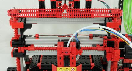
Open the upper drive chain and adjust both sides so the height is the same on both sides. To do so, move the axle upward and clamp a fischertechnik building block at the left and right between the fixed and movable parts. When these blocks are clamped with the same pressure, the X-axis is optimally aligned in the horizontal plane. Now close the drive chain without rotating the two spindles against each other.


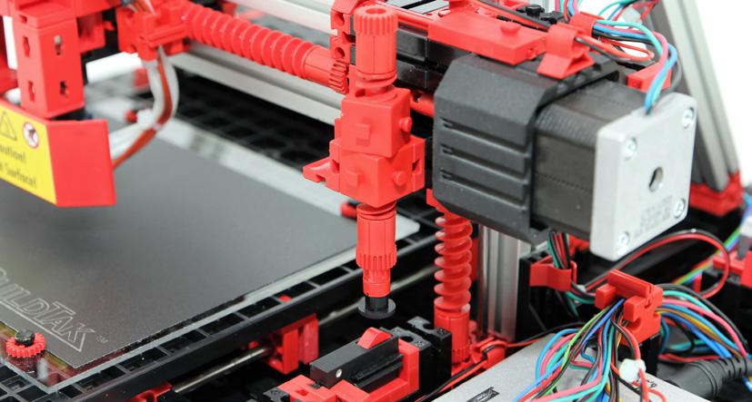
Before starting the first print job, the printing bed and printing head must be aligned. This is the only way to ensure a perfect printing result! The goal of the calibration is to set the distance between the printing bed and the needle tip of the printing head to about 0.2 millimeters by using the adjustment card provided, so the first layer of filament – the print material – adheres to the printing bed. The limit switch on the right side of the printer below the X-axis takes on an important function here (see illustration).

The limit switch is used to control the lowering of the printing head to the printing bed in the end position. As this happens, the needle tip must not be permitted to strike the printing bed, or damage will result! Carry out this step with especial care. To do so, it is best to carefully remove the protective cover from in front of the printing head as show in the following illustration.

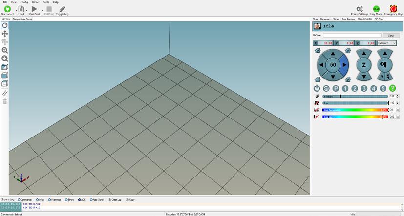
Now change to the item “Manual Control” in the printing software “3D Print Control”. Here you will find the “Home” icon for the printing head start position.

Now use the included adjustment card to check the distance between the needle tip of the printing head and the printing bed. The adjustment card should just fit between the nozzle and the printing bed and be pulled through easily.

If the distance is not set correctly, adjust it as follows: Move the printing head by turning the upper spindles (Z-axis) upward or downward far enough that the needle tip touches the card. Then turn the adjustment screw for the limit switch far enough that the switch is pressed with an audible “click”. Now you have adjusted the stop position of the printing head. Next, please lock the adjustment screw. Then press “Z-Home”. The Z-axis moves upward slightly and then returns to the limit switch. Now you can recheck with the adjustment card to see if the nozzle distance is correct; readjust it as necessary.
Next, make the following setting at all corner points of the printing bed. First, use the right arrow button to manually move the printing head to X-position “100”. Use the adjustment card to recheck the distance at this position. If the distance is not correct, readjust it at this position as described above by opening the drive chain and correcting one of the spindles so the distance from the nozzle to the printing bed is correct. Now re-close the chain. Move in the Y-direction to the value “100” and check the nozzle distance. If there is a deviation in this direction, you can use one of the delivered hole reinforcements to raise the printing plate slightly and then simply adhere the reinforcement beneath the printing plate.

Loading print material (filament)
To insert the filament (print material), first heat the 3D printer to operating temperature (200 °C). To do so, click the “Heat Extruder” icon at the lower left of the “Manual Control” tab and wait a minute until the printing head heats up.
Then the filament can be inserted up to the printing nozzle by strongly pushing the lever on the material feed. To make it easier to insert the filament, carefully bend the first centimeter to straighten it. The filament is correctly inserted when molten material is discharged from the nozzle. Additional options to control the extruder and the filament transport are available in the operating field “Manual Control”.

Exchanging or removing print material (filament)
To change the filament, repeat the above steps in reverse order. First preheat the extruder and let the material transport move backward until you can pull out the filament by hand. Remember to switch off the printing head heat when finished to prevent overheating!


