
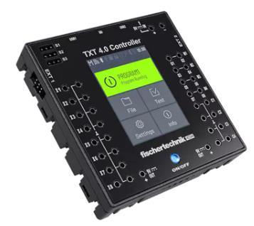
ROBO Pro Coding und TXT 4.0 Controller
In its multilingual programming environment, the ROBO Pro Coding software from fischertechnik offers the option of graphical programming with Blockly as well as textbased programming via Python3 with the TXT 4.0 controller.

ROBO Pro Coding is available for Windows, Mac, Linux, Android, and iOS operating systems:
https://www.fischertechnik.de/en/apps-and-software
The documentation for Blockly in ROBO Pro Coding can be viewed at the following link:
https://doc.fischertechnik-cloud.com/en/blockly
The documentation for the fischertechnik TXT 4.0 controller can be found here:
https://www.fischertechnik.de/en/toys/e-learning/txt4-0-controller
If you have any questions about the content of this document or the tutorial, please contact:
fischertechnik-technik@fischer.de
Tutorials STEM Coding RoboMission
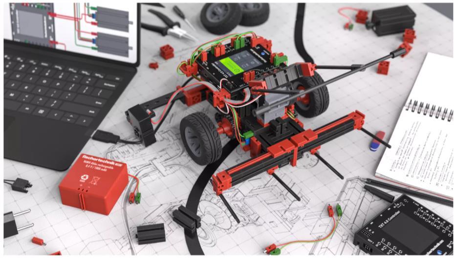
This document describes examples of how the sensors and actuators from the STEM Coding RoboMission robotics set can be used. All examples are based on the robot's model proposal but can also be used for your own models.
All relevant examples in this document can be imported directly into ROBO Pro Coding from fischertechnik GitLab. For this purpose, the name of the program can be entered in the search field under Menu -> Import -> fischertechnik GitLab and the corresponding program example can be loaded directly.

Please note that this tutorial assumes that you are already familiar with ROBO Pro Coding and know the basics of ROBO Pro Coding. The following topics relevant to RoboMission will be covered in the next chapters, whereby the level of difficulty can be classified as follows:
simple
advanced
complex
To familiarize yourself with the components included and to get started with ROBO Pro Coding, we recommend watching these videos:
• First steps with the TXT 4.0 controller
• The fischertechnik encoder motor
• The fischertechnik servo motor
• The fischertechnik color sensor
• The fischertechnik RGB color sensor
★ Encoder Motor und Servo
A maximum of 4 encoder motors (M1-M4, C1-C4) and a maximum of 3 servo motors (S1-S3) can be connected to a TXT 4.0 controller at the same time
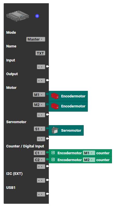
To do this, the corresponding motors are first assigned to the outputs in the controller configuration in ROBO Pro Coding and can then be selected in the main program.
Direct Motor Control
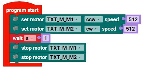
In the simplest case, the two encoder motors can be controlled without using the encoders by directly setting the direction of rotation - clockwise (CW) or counterclockwise (CCW) - and the speed value (0 ... 512) for the pulse width modulation (PWM).
The following program switches the two motors on for 1 second and stops them after the waiting time has elapsed.
The disadvantage of direct control is that the two motors are not synchronized with each other, i.e. one motor is always switched on and off first and the other shortly afterwards. In addition, external influences on the motors and the different friction between the wheels have a negative effect on the robot's behavior. It is therefore not possible for the robot to move precisely in a straight line.
Advanced motor control with synchronization of the motors
The firmware of the TXT 4.0 controller includes an extended motor control function that already performs synchronous control based on the encoder signals.
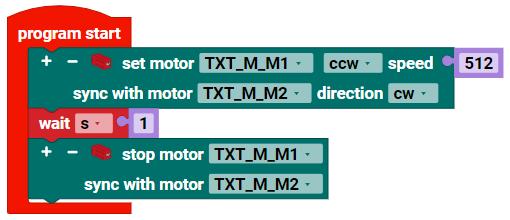
With the following blocks, the two motors M1 and M2 are moved synchronously with each other, and the synchronous run is then stopped again after 1 second. If one motor is blocked during this time, the other motor follows the first motor. Synchronization is relevant, for example, when the robot moves in a straight line.
Advanced motor control with synchronization and distance specification
In addition to synchronous operation, a distance (number of pulses for the encoder) can be specified. This can then be carried out either for a single motor or for several motors synchronously.
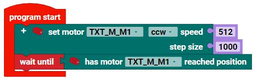
The status from the extended motor control can be queried with the “has motor ... reached position” block. The motor control uses the status to signal that the position has been reached so that program execution can be
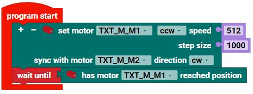
continued. Once the distance has been reached, e.g. after 1000 pulses, the motor is then stopped automatically
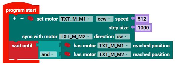
Normally, it is sufficient to query the status of one motor. However, the status of all motors can also be queried to ensure that the controller takes all motors into account in the event of a cable break in an encoder.
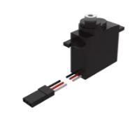
Servo Motor Control
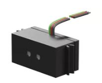
In contrast to the motor, which is usually used to drive the robot, the servo motor can be used to approach absolute angles of approx. -90 ... 90 degrees directly. The control and sensors are already included in the servo motor. The servo motor is ideal for robot gripping devices, for example, wherever rotary movements are required.
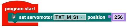
The servo motor moves to a specific angle by specifying a PWM value. The specification is absolute. The central position of the servo is approx. 256 and the two limits are 0 and 512. The absolute values specified differ slightly depending on the servo. They should therefore be calibrated individually for each servo. This can be done using constants or variables in the program, for example.
It should also be noted that the servo has no feedback in relation to the controller. The servo attempts to reach the specified position via the PWM value. If the target position of the servo were permanently mechanically blocked, a very high current could flow through the servo. This could then damage the servo. This should be avoided at all costs when using the servo
★ Optical Color Sensors
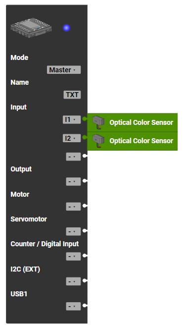
Digital or analog sensors can be connected to the universal inputs (I1-I8) on a TXT 4.0 controller
To do this, the corresponding sensors are first assigned to the inputs in the controller configuration in ROBO Pro Coding and can then be selected in the main program
2x
The STEM Coding RoboMission set includes two optical color sensors that can be used to detect simple light-dark transitions on the course, e.g. black track. The optical sensor can also be used to detect blackwhite transitions, e.g. gray values. This can be used to align the robot precisely to the line or to implement a line follower.
The analog value of the two sensors can be read out with the following blocks: The analog value corresponds in mV to the voltage measured at the two inputs I1 and I2.
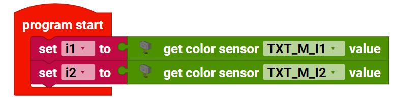
Please note that the RGB color sensors are not connected to the universal inputs, but to the I2C bus (EXT1 or EXT2 connection) of the TXT 4.0 controller. The RGB color sensor is also included in the set and is covered in the chapters below
★ Interface Test
The actuators and sensors can also be tested quickly without a program. The interface test in ROBO Pro Coding can be used for this when a connection to the TXT 4.0 controller is established

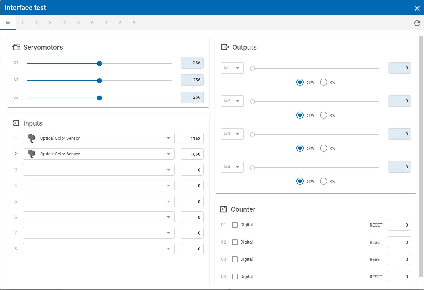
For servo motors S1-S3, the value can be set using the slider.
For motors M1-M4, the speed and direction of rotation of a motor can be set. The value is displayed for the universal inputs I1-I8, e.g. for the optical sensors. The individual universal inputs must be configured beforehand via the selection box.
The current counter value C1-C4 for the encoder inputs is also displayed as a value.
Please note that the interface test and a program cannot be started at the same time.
★★ Python Modules, Functions, and Imports
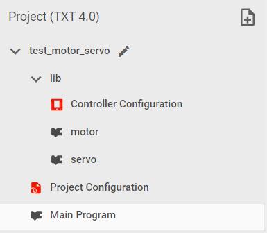
In the RoboMission_motor_servo program example, functions for motors and servo motors are defined in additional files that can be found in the structure under “lib”. The advantage of having your own Python modules is that the code is clearer and can be reused as a library in other projects
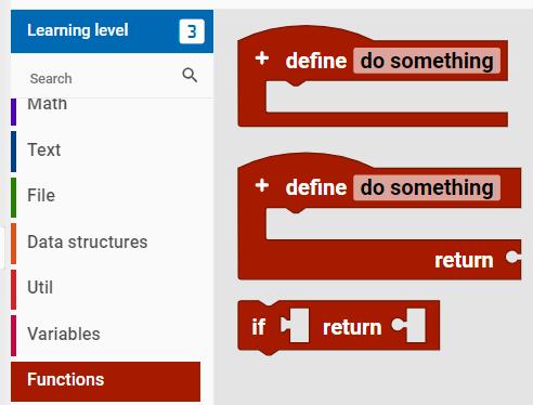
Functions that are available locally in the module or in the main program are defined with “Functions”. Functions can be defined with parameters as well as with return values
The parameters are added with (+) and defined accordingly.
If the functions are to be used in other files, they can be added via “Imports”. To do this, switch to the file in which the function is to be used and select this function from another module via “Imports”.
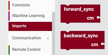
The local functions “Functions” and imported functions “Imports” have different colors. This allows you to differentiate between them in the program flow.
Please ensure that you do not define any circular references between the modules. Modules must not import each other's functions, otherwise the imports cannot be resolved correctly.
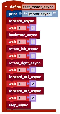
★★ Motor Control as Library [RoboMission_motor_servo]
The RoboMission_motor_servo example shows how an (encoder) motor and a servo motor can be controlled.
Please familiarize yourself with how encoder motors and servo motors work before you look at the program. You will find the technical data for the motors in the respective data sheets.
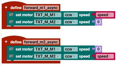
In the “motor” module, various functions are defined with which the motors can be controlled asynchronously (without the use of encoders) or synchronously (synchronized using encoders)
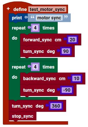
If the two motors are moved synchronously, the control waits until both motors have reached a certain number of pulses. If one motor is blocked in the meantime, the second encoder motor remains stationary until the first motor has also reached the position. For precise movements of the robot on the course, the two motors must always be synchronized.
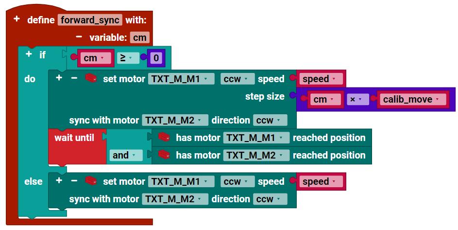
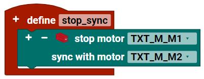
A distance can also be specified. If the distance is to be infinite, a negative parameter, e.g. -1, can be passed to the forward_sync function. The two motors then move endlessly synchronously until both motors are stopped again with stop_sync.
So that the movement of the robot can be specified in the motor functions, e.g. in the unit cm or in degrees, the pulse counters of the encoder must be converted with the corresponding factors in the program. These factors are included in the calibration function. If the model of the robot, in particular the wheel distance and wheel diameter from STEM Coding RoboMission, is changed, the factors calib_move and calib_rotation must then be adapted to the new model accordingly
In the case of a line follower or complex control, it is best if the two motors are not synchronized with each other. For these applications, it is advantageous to set the speed directly via pulse width modulation (PWM) so that the two motors can be set quickly and independently of each other
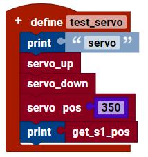
The “servo” module contains functions for the servo motor. The servo motor has its own control and is given an absolute position via (PWM: 0...512), which it tries to control as quickly as possible. Very large currents can sometimes flow for a short time and, depending on the current position, the movements can then be very jerky. To avoid jerky movements in the servo motor, intermediate positions must be specified by the program at certain intervals. Slow movements are then also possible with the servo motor.
The values for the individual positions can also be calibrated for the servo motor. This is necessary because each servo has slightly different absolute positions due to the tolerances.
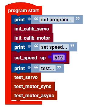
The main program in RoboMission_motor_servo then looks like this:
★★ START Button and TXT 4.0 GUI [RoboMission_display_start]
The example RoboMission_display_start shows how a graphical user interface (GUI) can be created on the display of the TXT 4.0 controller in ROBO Pro Coding. Various elements are available in ROBO Pro Coding on the left sidebar in the GUI editor


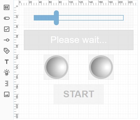
The following elements are used in this example:
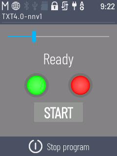
Button (1): Starting the program sequence
Slider (2): Setting variable values
Label (3): Output of text
Status indicator (4): Output of binary states

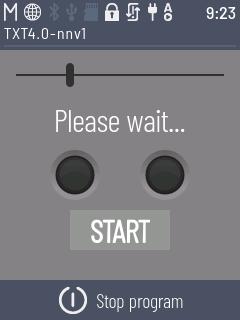

On the left is the definition in the GUI editor, on the right is the representation on the TXT 4.0 display.
The interface on the display can be configured as required. The font size and font style can also be set in the properties of the elements.
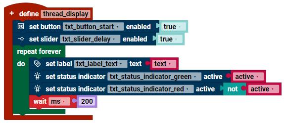
The program sequence must be defined so that actions can be triggered via the interface or program statuses can be shown on the display. It is also recommended to provide a separate thread (a separate endless loop) for updating the display. As the eye is sluggish, the display should be updated every 200ms ... 1s at most. In addition, a separate thread for the display relieves the main loop, in which the robot is often controlled, and the response time must be very short.
Loading the interface usually takes a few seconds. To ensure that no elements can be activated during initialization, all elements that trigger an action can be deactivated in the properties at the beginning. When the display thread is initialized, the corresponding elements can then be specifically activated with set ... enabled.
Callback functions must then be defined for all actions (e.g. “on button ... clicked” and “on slider ... moved”), which set variables for the corresponding events. These can then be evaluated in the main program
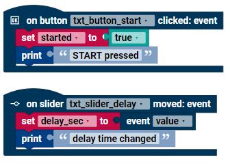
In the callback functions, it is recommended to call only short functions and no blocking functions, as otherwise the callback functions can influence each other.
The program sequence in the main loop can then look like this:
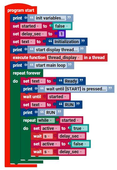
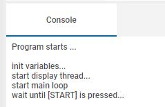
To better understand the program, it is often advisable to provide output with print(...) in the program flow in addition to the output on the display. When the program is then started in ROBO Pro Coding, all outputs with print() in the console can help with the analysis of the program as to when which instruction was executed in the program. However, for control loops with short response times of e.g. 10ms, the print() output should be avoided
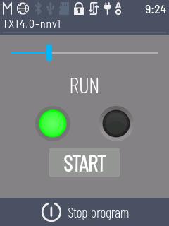
The following shows the output on the TXT 4.0 controller display when the program is executed. The status first changes from “Please wait ...” to “Ready” and finally to “RUN”.
With the START button, for example, it is now possible for the robot to start the program sequence only when START is pressed
★★ Line follower with optical color sensors [RoboMission_line]
The RoboMission_line example shows how a simple line follower can be implemented with optical color sensors at the universal inputs.
Optical color sensors provide an analog voltage as a value in mV depending on how much light is reflected from the course. White areas have a low value, black areas a high value. If the sensor is located at the edge of the line, the value read from the sensor is between the two minimum and maximum values.
Because each optical color sensor has slightly different min and max values, it is advantageous to calibrate each sensor individually. For example, a 360degree rotation can be carried out and the min and max value for each sensor can be determined and saved from all measured values. The calibrated values can then be used in the calculation.
If the robot is placed on a line and the calib_line_rotate360 function is then executed, the min and max values per sensor are calibrated and saved in the corresponding variables:
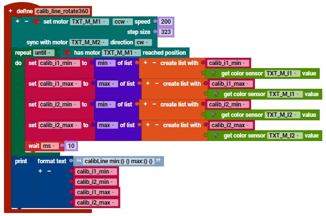
The values calibrated with this function can look as follows, for example:
calibLine min:173 171 max:1559 1485
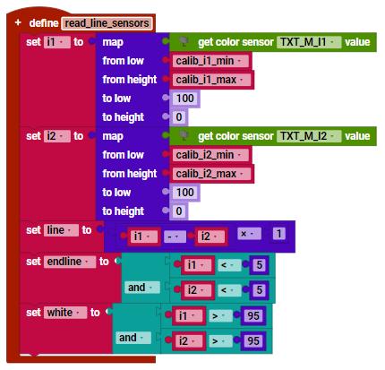
In the read_line_sensors function for reading the sensors, the measured values are then normalized so that the line variable has values between -100 ... 0 ... 100. In addition, several Boolean variables are set to indicate whether a line end has been detected or a white area has been detected. These states can then be used to perform a 180-degree turn at the end of the line or to stop the line follower when the robot passes the white area
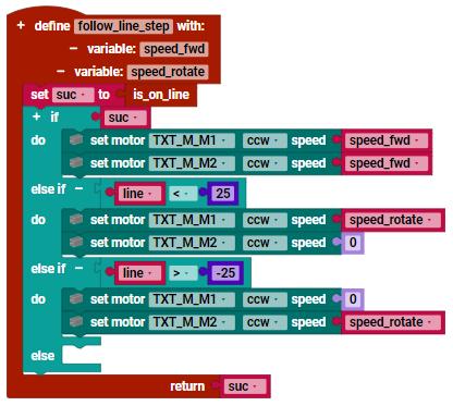
The function follow_line_step is then called in an infinite loop, which controls the motors depending on the calculated variable line. The robot moves one step straight ahead, to the left or to the right. This happens at very short intervals
The main loop in the program can then look like this, for example:
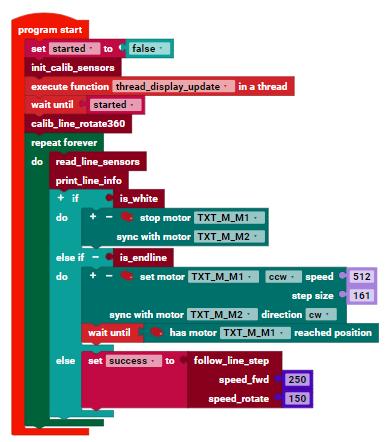
If the speed of the motors is set too high, the robot will lose the line very quickly. If the speed of the motors is set too low, the power of the motors will not be sufficient when the battery charge is low, or the robot will move very slowly along the line.
Many different methods are conceivable with a line follower. For example, a line edge can be followed instead of the line. In this case, the follow_line_step function must be adapted accordingly.
The line follower can be further improved with a PID controller so that the robot does not lose the line even at a very high speed. The implementation of such a PID controller requires knowledge of control technology, which will not be discussed further in this tutorial.
★★ Python Code with Blockly
Most of the functions in ROBO Pro Coding can be implemented with Blockly. There are many blocks for different use cases. It is very convenient to use the blocks because the required instructions in Python are generated automatically with ROBO Pro Coding.
However, sometimes Python commands need to be integrated into Blockly programs because the corresponding block does not yet exist or because the sequence of Python commands needs to be defined differently. This can be done very easily in a Blockly program by creating the required Python commands with the following Python blocks:
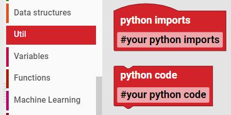
The “python imports” block can be used to import specific Python modules. The blockly generator places the content at the beginning of the file.
The “python code” block can be used to define Python code anywhere in the blockly program.
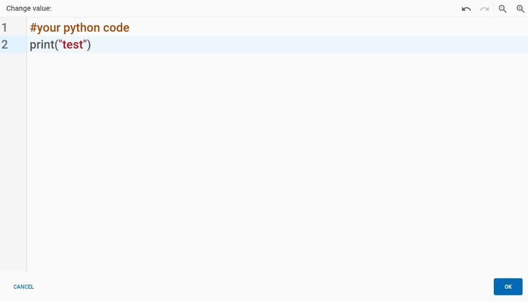
A Python editor opens when the block is clicked. Python code can then also be defined over several lines.
Particular attention must be paid to the indentation of the source code, as in Python the indentation via spaces or tabs has a significant influence on the structure of the program.
★★ RGB Color Sensor as Library [RoboMission_rgbw_hsv]
RGB color sensor is connected to the I2C bus of the TXT 4.0 controller. To do this, an RGB color sensor must be connected to the EXT1 or EXT2 connection of the TXT 4.0 controller using a ribbon cable.
In contrast to optical color sensors, which are connected to the universal inputs of the TXT 4.0 controller, the RGB color sensor is well suited for detecting obstacles of different colors if they are to be detected at a greater distance. Several sensors can also be used with the RGB color sensor, which are then connected to the main sensor in a chain.
The example program
RoboMission_rgbw_hsv shows how the sensor values can be read out
The log module contains functions for logging, whereby the logging level can be changed.
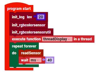
The rgbcolorsensor module contains all the basic functions for reading the registers of the RGB color sensor. All functions required for communication with the RGB color sensor are implemented here.
The rgbcolorsensorutil module contains further functions, e.g. to convert color values from the RGBW model (Red, Green, Blue, White) into the HSV model (Hue, Saturation, Value) or as HEX values. In addition, some case distinctions for the standard colors are already implemented.
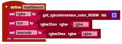
The values of the sensor with the index 0 (main sensor) can then be read out as follows, for example:
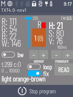
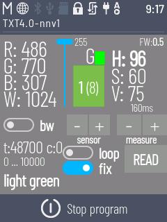
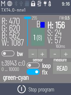
Another example program test_rgbcolorsensor_smbus shows how the complete interface of the RGB color sensor can be used. Various additional interfaces can be found in the screenshot
(1) Raw values of the RGBW sensor: Red/Green/Blue/White
(2) Brightness LEDs adjustable 0...255
(3) Calculated HSV values: Hue/Saturation/Value
(4) fixed: Reference value for HSV calculation either fixed (10000) or adaptive with measured min ... max values from the history
(5) Recognized block color R/G/B/Y
(6) Recognized color as HEX value
(7) Detected color as general text
(8) Sensor 1 (of 8 detected sensors), is selected via (-) and (+) buttons
(9) Set time “160ms” for measurement, is selected via (-) and (+) buttons
(10) bw: Switch for black/white mode

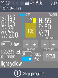
(11)loop: Endless measurement, if activated
(12) Start single measurement with “READ” if loop is deactivated (13) Firmware version FW: 0.5 of the connected sensor
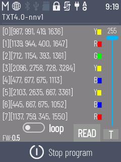
The example test_rgbcolorsensors_smbus shows how several RGB color sensors (index 0-7) can be read out and the values of all sensors can be shown simultaneously on the display
★★ Measuring the battery voltage [test_battery]
The charge status of the battery connected to the TXT 4.0 controller can have an influence on the current applied to the motors and thus affect the behavior of the robot. To be able to react to low voltage, the voltage can be read out in volts via an internal voltage input of the TXT 4.0 controller.
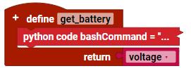
In the test_battery example, the voltage and therefore the approximate state of charge can be read out using a Python function
Template for your own projects
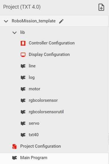
The RoboMission_template example can be used to create your own project
Import this project and modify it according to your own requirements.
The functions used in this tutorial are included as modules and can be used in the main program or in other newly created modules.
Build your own template and use it for your own projects
★★★ Line follower with PID controller [RoboMission_linepid]
The RoboMission_linepid example shows how a PID controller can be implemented in the line follower.
In Python, for example, the simple-pid library exists for this purpose. Version 1.0.0 of this external library is already included in the firmware of the TXT 4.0 controller 3.1.8 and can be used directly. The documentation for simple-pid can be found under the following link:
https://github.com/m-lundberg/simple-pid/tree/v1.0.0
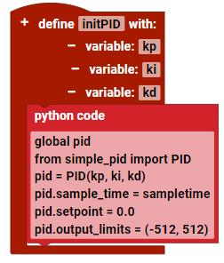
First, the PID controller is initialized, whereby the parameters Kp, Ki and Kd must be set. The setting of the constants must be determined experimentally and can be very time-consuming. For the basics of PID and the correct selection of parameters, please refer to the relevant external literature
Meaning of the parameters:
• Proportional term Kp
• Integral term Ki
• Derivative term Kd
The following functions are called in each step of the control loop:
In the first step, the sensors are read out.
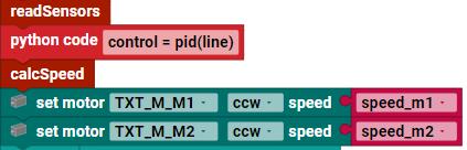
The calculation is then carried out in the PID controller. The variable line (100 ... 0 ... 100) is the control variable. The setpoint is in the middle of the line at the value 0.
The speeds for the two motors are then calculated and set. Please note that the speed of the motors must be limited to values between -512 and 512.
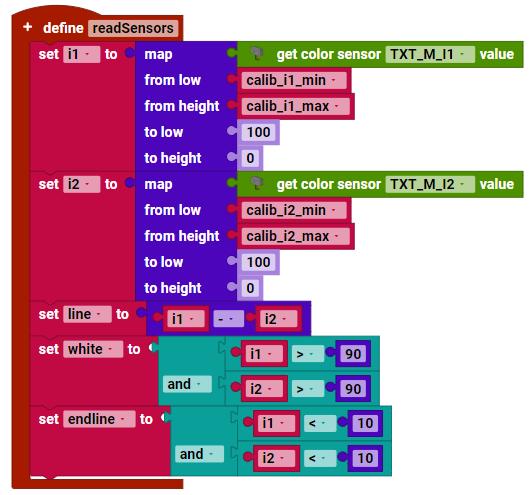
The sensor values are read out in the readSensors function and standardized to the calibrated values. To do this, the calibration routine is called once at the start of the program, in which the min and max values are set. If the min and max values do not change, the values can be set directly in the program during initialization. In this case, the calibration function does not need to be called up.
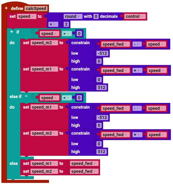
The speed is calculated in the calcSpeed function.
Experiment with different parameters
Kp, Ki and Kd. Also try changing the speed of the motors. If the values are set correctly, the robot should then follow the line even more precisely
What's Next
In addition to the STEM Coding RoboMission set, fischertechnik offers many other additional components and individual parts that can also be used.
Look at the fischertechnik homepage http://www.fischertechnik.de/en.