33 minute read
Steel Dynamics to buy Mexican Metals Recycler


INDUSTRY NEWS / 行业新闻 Steel Dynamics to buy Mexican Metals Recycler Steel Dynamics公司计划收购墨西哥金属回收公司
Steel Dynamics, Inc., one of the largest U.S. steel producers and metals recyclers, recently announced its planned acquisition of ROCA, a Mexican recycling company in a cash-funded deal. ROCA’s primary operations are comprised of four scrap processing facilities, strategically positioned near high-volume industrial scrap sources located throughout Central and Northern Mexico. These combined facilities currently ship approximately 575,000 gross tons of scrap annually and have an estimated annual processing capability of approximately 850,000 gross tons.
Advertisement
“We look forward to adding ROCA to the Steel Dynamics family to further solidify our Southwest U.S. and Mexico growth strategy,” said Mark D. Millett, chairman, president and chief executive officer.
“Combined with our existing North American metals recycling facilities, the addition of ROCA significantly strengthens our raw material procurement strategy in the region. After closing the ROCA transaction and fully integrating our Mexican metals recycling operations, we believe our Mexican scrap facilities will provide an even more meaningful competitive advantage to our U.S. electricarcfurnace steel operations, while also providing a high-quality, customercentered option for our outside scrap customers. We are very excited to welcome and learn from the entire ROCA team.” ■
近日,美国最大的钢铁生产商和金属回收商之一Steel Dynamics公司宣布,将计划以现金资助的方式收购墨西哥资 源回收公司罗卡公司(ROCA)。ROCA公司有4个废料处理厂, 工厂专门设立在墨西哥中部和北部,那里有大量的工业废料产 生。目前,每年输送到这些工厂的废料约575000t,年处理能 力约为850000t。 “我们期待着在ROCA公司加入到Steel Dynamics大家 庭后,将可以进一步巩固我们在美国西南部和墨西哥的发展战 略,”Steel Dynamics公司董事长、总裁兼首席执行官Mark D.Millett表示。 “在现有北美金属回收厂的基础上,ROCA公司的加入将 大大加强我们在该地区的原材料采购战略。在完成ROCA公 司的收购并完全整合我们的墨西哥金属回收业务后,我们相信, 公司的墨西哥金属回收厂将为我们的美国电弧炉钢铁生产注入 更有意义的竞争优势,同时也为公司的其他废金属回收客户提 供高质量、以客户为中心的选择。我们对ROCA公司的加入 感到非常高兴,并向整个ROCA团队学习。”■
MEITECH, International Summit of Die Casting & NADCA South Congress 20 23
APRIL 19, 20 & 21. 2023 Centro de Convenciones de San Luis Potosi. ADRIANA TAVARES VELASCO San Luis Potosi, México. adriana.tavares@meitechexpo.com 52 442 149 629 www.meitechexpo.com
CHINA’S TOTAL CASTING PRODUCTION REACHED 54.05M TONS IN 2021
2021年中国铸件产量达到5405万吨
During the Seventh Forum on National Foundry Industry Innovation and Development held on July 26, the data of China’s foundry industry in 2021 has been officially released by Mr. WANG Dongsheng, the newly elected Executive Vice President and Secretary General of China Foundry Association.
Total casting output
In 2021, the total output of China's castings reached 54.05 million tons, with a year-on-year increase of 4.0%, and an average increase of 5.3% in two years. The foundry industry has maintained relatively stable development. Casting output in different materials
Gray iron: 22.55 million tons; Ductile iron: 15.95 million tons; Malleable iron: 600,000 tons; Steel casting: 6.6 million tons; Aluminum (magnesium) alloy: 7.2 million tons; Copper alloy: 900,000 tons; Other casting: 250,000 tons.
Casting demand of downstream industry
Automobile: 15.4 million tons;
Internal combustion engine and agricultural machinery: 5.55 million tons;
Engineering machinery: 5.2 million tons;
Mining, metallurgical and heavy machinery: 5 million tons;
Cast pipes and fittings: 8.85 million tons;
Machine tools: 2.6 million tons;
Rail transit: 2.15 million tons;
Power generation equipment and power: 2.35 million tons;
Ship building: 350,000 tons;
Other: 6.6 million tons.
The automobile industry is the largest market of castings, auto casting accounts for 28.5% in 2021’s total production. Driven by exports growth, the output of automobile castings increased by 2.7% year-on-year; The demand for castings in machine tools, general machinery and emerging industries has increased, such as robots. ■
2022年7月26日,在第七届全国铸造行业创新发展 论坛上,2021年中国铸造行业数据正式发布。中国铸造协 会执行副会长兼秘书长王东生进行了数据发布与详细解读。
铸件总产量
2021年中国铸件总产量达到5405万吨,同比增长 4.0%,两年平均增长5.3%,铸造行业实现了相对平稳的 发展。
分材质铸件产量
灰铸铁铸件产量2255万吨; 球墨铸铁铸件产量1595万吨; 可锻铸铁铸件产量60万吨; 铸钢铸件产量660万吨; 铝(镁)合金铸件产量720万吨; 铜合金铸件产量90万吨; 其他铸件产量25万吨。
下游行业铸件需求
汽车铸件1540万吨; 内燃机及农机铸件555万吨; 工程机械铸件520万吨; 矿冶重机铸件500万吨; 铸管及管件885万吨; 机床工具260万吨; 轨道交通铸件215万吨; 发电设备及电力铸件235万吨; 船舶铸件35万吨; 其他铸件660万吨。汽车工业是铸件最大需求用户, 2021年汽车铸件占比为28.5%,由于出口的拉动作用,汽 车铸件产量同比增长2.7%;机床、通用机械及新兴产业如 机器人等领域铸件需求增加。■
The Situation of Pakistan Foundry Industry

Pakistan Foundry Association
巴基斯坦铸造行业现状
巴基斯坦铸造协会
Casting output and foundries
There are about 1530 foundries in Pakistan, out of these foundries, their production capacity is 400,000 tons and the current production is 250,000 tons. Bulk of production is basically castings in MS steel, Gray iron, Ductile iron and non-ferrous etc.
The Foundry industry of Pakistan is engaged in the production of automotive parts, tractors, sugar mills machinery parts, cement factories consumables, chemical factories consumables, agriculture implements, heavy industrial castings, pumps, valves, electric motors, textile and cement machinery, processing industries and others.
Challenges
The biggest challenge of the foundry industry in Pakistan is to change in mindset for adopting new technology. The foundry industry of Pakistan seems to be suffering from a lack of awareness of new technologies & skills development of the foundry staff. We have challenges with our local foundry industry and we want international associations to guide us on the association level. We want to create awareness through technical seminars conducted by global foundry experts to teach the new foundry practices. ■ 巴基斯坦铸件产量及铸造企业数量
巴基斯坦有大约1530家铸造厂,总产能可以达到 400,000吨,目前的产量为250,000吨。主要铸件产 品为玛钢、灰铸铁、球墨铸铁和有色金属等。 巴基斯坦的铸件产品主要应用于汽车零部件、拖拉 机、制糖设备零部件、水泥厂耗材、化工厂耗材、农机 工具、重工业、泵、阀、电机、纺织和水泥机械等加工 工业领域。
挑战
目前,巴基斯坦铸造业面临的最大挑战是急需改变 旧有的思维模式,引进新的铸造技术。巴基斯坦铸造业 的发展因缺乏新技术和对新技能的了解而受到很大的制 约。巴基斯坦的铸造行业面临着巨大的挑战,希望国际 铸造行业协会给与指导,例如通过举办有全球铸造专家 参与的技术研讨会,带来新的铸造技术和实践经验,从 而提高巴基斯坦铸造业对新技术的了解。
INTEGRATION OF MICROPOROSITY PREDICTION IN DURABLE AND ROBUST COMPONENT DESIGNS OF HIGHLY LOADED ALUMINUM CASTINGS
M.Sc. M. Weidt, MAGMA Gießereitechnologie GmbH, Aachen, Germany Prof. Dr.-Ing. A. Bührig-Polaczek, Foundry Institute, RWTH Aachen University
将微观缩孔预测集成到高负载铝铸件 的耐久和稳健部件设计中
德国亚琛迈格码公司 理学硕士M. Weidt 亚琛工业大学铸造研究所 Dr.-Ing A. Bührig-Polaczek博士
1.Abstract
Cyclically loaded cast aluminum components continue to be subjected to strong pressure to increase power density, particularly through increased specific loads or by weight reduction. To achieve these goals, it is necessary to fully exploit the material-specific performance potential. At the same time, robust manufacturing processes require precise knowledge of the main influencing variables linking process parameters, component design, and component performance. A closed simulation chain and the systematic use of virtual test plans (DoE) promise the targeted development of components and optimized and robust production. This paper presents in detail one of the main influencing variables in the simulation chain, the relationship between the existing local porosity and the resulting defect size. In an integrated approach, the obtained information will be used to predict the local fatigue strength and combined with the residual stress state to predict the fatigue performance for an aluminum cylinder head. By validation component tests it can be shown that only this integrated approach allows a satisfactory failure prediction under cyclic loading.
2.Motivation and Background
Combustion engines are subjected to static and cyclic loads during operation. In particular, the cyclic loads that can be borne depend not only on the alloy composition and local microstructure but also to a large extent on existing microstructural defects. During the solidification of aluminum castings, it is hardly possible under real production conditions to completely avoid a certain number of property1.摘要
为了提高功率密度,特别是通过增加比负载或减轻重量, 循环加载的铸铝部件持续承受强大的压力。为了实现这些目标, 有必要充分挖掘材料特定的性能潜力。同时,稳健的制造工艺 需要准确了解连接工艺参数、部件设计和部件性能的主要影响 变量。封闭的仿真链和虚拟测试计划 (DoE) 的系统使用保证 了组件的目标开发以及优化和稳健的生产。本文详细介绍了模 拟链中的主要影响变量之一,即现有局部孔隙率与由此产生的 缺陷尺寸之间的关系。在集成方法中,获得的信息将用于预测 局部疲劳强度,并结合残余应力状态来预测铝制缸盖的疲劳性 能。通过验证组件测试可以表明,只有这种集成方法才能在循 环加载工况下取得令人满意的失效预测。
2.动机和背景
内燃机在运行期间承受静态和循环载荷。尤其是 可以承受的循环载荷不仅取决于合金成分和局部微观 组织,而且在很大程度上取决于现有的微观组织缺陷。 在铝铸件凝固过程中,在实际生产条件下,几乎不可 能完全避免一定数量的金属间化合物相、夹杂物或微 观缩孔等降低性能的缺陷。在这些缺陷中,微观缩孔 通常是微观组织中最大的局部缺陷,因此显著决定着
疲劳性能。 [1],[2]
在减轻内燃机重量的同时提高功率密度的持续努
reducing defects such as intermetallic phases, inclusions, or micropores. Among these defects, micropores often represent by far the largest local defect in the microstructure and therefore significantly determine the cyclic properties [1], [2] .
The ongoing efforts to reduce the weight of internal combustion engines while at the same time increase power density are increasingly raising the requirements for full utilization of the material's strength potential.
Design decisions have a direct impact not only on the load distribution of the component but also on the local material properties and defect distributions. Faster solidification leads to a finer microstructure formation, which is usually associated with advantageous material properties. However, design decisions can also have a negative influence on the local solidification behavior and can increase the formation of porosity, as well as cause or intensify residual stress-related casting defects such as hot tearing and cold cracks. It is of great advantage to assess the consequences of decisions regarding cast part and casting process design while still in the planning stage. At this point, the virtual design of experiments (DOE) tool is available as part of the integrated casting process simulation. By systematically working through virtual experiments, safe process windows can be identified at the design stage of the casting. The complex interactions between component design, manufacturing conditions, and unavoidable fluctuations in manufacturing become manageable by a virtual DOE.
The results presented in this paper are based on the systematic analysis of microporosity in a cylinder head using computed tomography at the micrometer scale. The goal of this work is to develop a better understanding of the relationships between porosity, pore size, and pore morphology. With this information available, a methodology to predict the local cyclic fatigue performance should be realized. The extension includes the effect of microporosity in addition to the influence of microstructure; thus it significantly improves the correct representation of the local material behavior of castings compared to the standard approach where only the local dendrite arm spacing (DAS) is considered. Moreover, it is shown that the residual stress state of the casting is a significant contributor to the actual failure behavior. 3.Casting Process
In this paper, the results of a cylinder head, manufactured by NEMAK Linz, Austria, using the Rotacast® process[3], are presented. Here, the melt is transferred from the holding furnace to a tundish by an automated pouring ladle. The tundish then docks with the prepared mold from below. A 180̊ rotational movement around the longitudinal axis fills the mold uniformly and with low turbulence. The cylinder heads were cast using two alloys, AlSi7Cu0.5Mg and AlSi8Cu3. Both alloys are typical for internal combustion engine applications, were melted from grain refined ingots and modified by
力中,对充分利用材料强度潜力的要求越来越高。 设计决策不仅对组件的载荷分布有直接影响,而 且对局部材料性能和缺陷分布也有直接影响。更快的 凝固导致形成的微观组织更细小,从而获得更有利的 材料性能。然而,设计决策也会对局部凝固行为产生 负面影响,并可能增加缩孔的形成,并导致或加剧与 残余应力相关的铸造缺陷,如热裂和冷裂。评估仍处 在规划阶段的铸件和铸造工艺设计是非常有利的。此 时,虚拟实验设计(DOE)工具可用作集成铸造工艺 模拟的一部分。通过系统地进行虚拟实验,可以在铸 件在设计阶段确定安全的工艺窗口。组件设计、制造 条件和制造中不可避免的生成波动之间的复杂相互作 用可以通过虚拟DOE进行管理。 本文介绍的结果基于使用微米级计算机断层扫描 对缸盖中的微观缩孔进行系统分析。这项工作的目标 是更好地理解孔隙度、缩孔尺寸和缩孔形貌之间的关 系。了解这些关系后,就可以实现一种预测局部循环 疲劳性能的方法。还可以了解微观组织和微观缩孔对 局部循环疲劳性能的影响;因此,与仅考虑局部枝晶 间距(DAS)的标准方法相比,它显著提高了铸件局 部材料行为的正确预测。此外,它表明铸件的残余应 力状态是实际失效行为的重要贡献者。
3.铸造工艺
本文介绍了由奥地利NEMAK林茨使用
Rotacast® 工艺制造的缸盖的结果。在这里,熔体
通过自动浇包从保温炉转移到中间包。然后中间包从
下方与准备好的模具对接。围绕纵轴的180°旋转
运动以低湍流、均匀地填充模具。使用两种合金,
AlSi7Cu0.5Mg和AlSi8Cu3,铸造缸盖。这两种合 金都是内燃机应用的典型合金,由晶粒细化的铸锭熔化
并在铸造前通过添加锶进行变质。
从缸盖的三个区域取样,每个区域具有不同的凝
固速率:燃烧室附近、中间甲板和凸轮轴轴承处。本
测试的目的是涵盖各种凝固条件以及产生的微观缩孔。
4. 微型计算机断层扫描和数据准备
孔隙率分布和缩孔形状的分析是基于30个试样, 每次从两种合金的缸盖上的三个位置取5个样(来自 五个缸盖)。取样是在奥地利莱奥本大学通用机械工 程系进行的。计算机断层扫描分析由奥地利莱奥本材 料中心使用GE nanotom m(XCT)进行。根据预
strontium addition before casting.
Samples were taken from the cylinder heads from three areas, each with different solidification rates: near the combustion chamber, in the tween deck, and the camshaft bearing. The objective was to cover a wide range of solidification conditions and the resulting microporosity。 4.Microcomputed Tomography and Data Preparation
The analysis of porosity distribution and pore shapes are based on 30 specimens, five specimens each (from five cylinder heads) in three positions and with two alloys. Sampling was carried out at the Department of General Mechanical Engineering at the University of Leoben, Austria. Computed tomographic analysis was performed by the Materials Center Leoben, Austria, using a GE nanotom m (XCT). Depending on the expected microstructure fineness, a spatial resolution of 3µm voxel size (rapidly solidified samples) and 8µm voxel size (slowly solidified samples) was used (voxel size=threedimensional equivalent to a two- dimensional pixel). At the resolution of 3µm and 8µm, respectively, the scanned sample volume averages at about 144 and 477 mm3 across all corresponding samples.
By setting a threshold value, each voxel was defined to be pore volume or dense metal. Digital image postprocessing was then used to artificially increase the resolution of the resulting pore volumes. Adjacent pore volumes were "merged" and analyzed as one larger pore. The criterion for aggregation was based on the distance between two pores and their equivalent spherical diameters: If the smaller equivalent sphere diameter met or exceeded the pore spacing, the pores were combined. The analysis routine used for this purpose was developed by the Department of General Mechanical Engineering at the University of Leoben in Austria. Details of the XCT measurements and analyses, as well as the suitability of the XCT radiation source, the required spatial resolution, the required size of the scanned volume, and data processing techniques, are discussed elsewhere by Garb et
al. [4]
Figure 1 shows a pore with its associated convex envelope. To characterize the size of each pore, the largest dimension of these envelopes was defined as the envelope diameter de.The maximum value within each sample is referred to below as the maximum envelope diameter de,max.
The measure of sphericity describes how far the quotient of volume to the surface area of a body deviates from that of a sphere. With the help of this quantity, the morphology of a pore can be characterized. Here, the sphericity must be within the values 1 "perfect sphere" and 0 "perfect deviation from a sphere". The sphericity of a pore is calculated using:
Here si and viare the surface area and volume of a
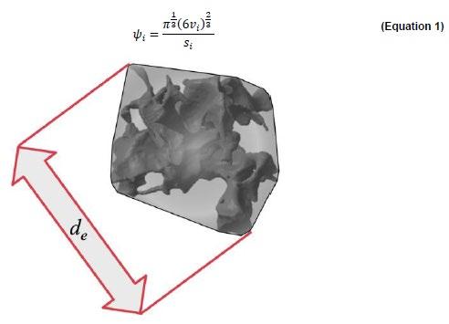
Figure 1: Representation of the largest dimension of a convex pore envelope (de)
图1: 缩孔包络体(de)的最大尺寸表示
图2:来自AlSi8Cu3缸盖中间甲板的XCT样品的三维表示。孔 隙率为0.176 %,孔隙包络体的最大直径为de,max2.75 mm。单个缩 孔的着色是随机完成的,仅用于更好地区分单个缩孔[5]。
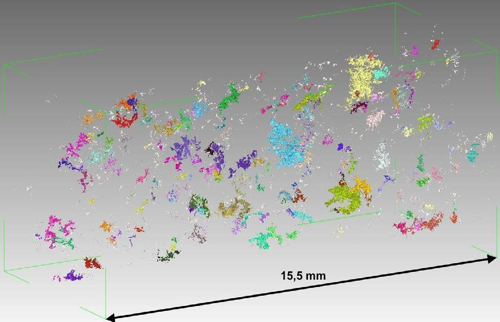
Figure 2: Three-dimensional representation of an XCT sample from the tween deck of an AlSi8Cu3 cylinder head. The porosity is 0.176%, the maximum diameter of the pore envelope is de,max 2.75mm. The coloring of the individual pores is done randomly and serves only for better differentiation of the individual pores [5].
期的微观组织的精细度,使用3µm 体素尺寸(快速 凝固样品)和8 µm体素尺寸(缓慢凝固样品)的 空间分辨率(体素尺寸=三维像素)。在分辨率分别 为3µm和8µm时,所有相应样本的扫描样本体积 平均约为144和477mm 3 。 通过设置阈值,将每个体素定义为孔隙体积或致 密金属。然后使用数字图像后处理来人为地增加所得 孔隙体积的分辨率。相邻的孔隙体积被“合并”并作 为一个更大的孔隙进行分析。聚集的标准是基于两个
In this equation, N represents the total number of all pores within a sample.
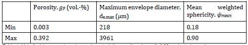
Table 1 summarizes the minimum and maximum characteristic porosity parameters determined by the previously presented methods. Table 1: List of minimum and maximum characteristic porosity values of all 30 evaluated samples

在该公式中,N表示样品内所有缩孔的总数。
表1总结了由先前提出的方法确定的最小和最大特征孔隙度参数。 表1:所有30个评估样品的最小和最大特征孔隙率值列表
single pore, respectively.
To describe the characteristic pore morphology within a sample, a volume-weighted mean sphericity ψmean is determined, also referred to as mean sphericity in the following. This parameter weights large pores, due to their volume, significantly stronger than small pores. In the conducted evaluations, this approach was shown to be very reliable with regard to the use of different resolutions in CT scanning. Also, it minimizes the influence of very small pores that lie at the resolution limit of the computer tomograph. These very small pores are the most errorprone ones and are negligible for lifetime prediction.
5.Result of the Pore Analyses
As can be seen from Table 1, there are significant differences between the measured values. The porosity varies from very low values of 0.003 vol% to moderate values of 0.392 vol%. Due to the non-standardized evaluation routine of the CT measurements as well as the post- processing of the data, no measurement error can be specified. Therefore the main focus lay on determining the pore size as robustly as possible.
Compared to the small variations in total porosity, significant differences occur for both the maximum envelope diameter de,max(about 0.2 to 4mm) and the characteristic pore morphology ψmean (0.18 to 0.90). This shows that the individual pores have significantly different shape characteristics within a narrow overall total range in
缩孔之间的距离及其等效球直径:如果较小的等效球 直径达到或超过孔间距,则将孔合并。用于此目的的 分析程序由奥地利莱奥本大学通用机械工程系开发。 Garb等人在别处讨论了XCT测量和分析的详细信 息,以及XCT辐射源的适用性、所需的空间分辨率、 所需的扫描体积大小和数据处理技术。 [4] 图1显示了一个带有相关包络体的缩孔。为了表 征每个缩孔的大小,这些包络体的最大尺寸被定义为 包络直径 de。每个样本内的最大值在下文称为最大 包络直径 de, max 。 球形度的测量描述了体积与物体表面积之比偏离 球体的程度。借助该量,可以表征孔的形态。此处, 球形度必须在值1“完美球体”和0“与球体的完美 偏差”之间。孔隙的球形度使用以下公式计算: 这里si和vi分别是单个缩孔的表面积和体积。 为了描述样品内的特征缩孔形貌,确定了体积加 权平均球形度 ψ mean ,在下文中也称为平均球形度。 由于大孔隙的体积,该参数对大孔隙的权重明显强于 小孔隙。在进行的评估中,这种方法被证明在CT扫 描中使用不同分辨率方面非常可靠。此外,它还最大 限度地减少了位于计算机断层扫描仪分辨率极限的非
porosity. A more precise understanding of the correlation between these variables is thus essential for quantitative statements about the material's application behavior.
Figure 2 shows exemplarily a sample of the alloy AlSi8Cu3 from the tween deck in 3D. The sample contains only 0.176% porosity but has a maximum diameter of the pore envelopes of 2.75 mm. The pores are highly tortuous, i.e. twisted and branched. Thus, a small absolute pore volume already leads to significant pore dimensions. A small amount of porosity can lead to defect sizes that are relevant for cyclic fatigue prediction.
Figure 3 shows the relationship between the maximum envelope diameter and porosity for the two investigated alloys. The trend is assumed to be linear in the first approximation and the scatter around the assumed linear relationship increases significantly with increasing porosity.
The presumed linear relationship between maximum envelope diameter and porosity is noteworthy in that all samples from both alloys follow the same trend despite being apart by about 2.5 wt% in copper and about 1 wt% in silicon as well as being extracted from three different positions with varying solidification rates.
The higher maximum porosity level exhibited by the AlSi8Cu3 alloy samples can be explained primarily by the increased copper content. Copper is known to destabilize the eutectic solidification front in cast aluminum alloys, causing the last solidifying zone to solidify in a spongy manner [6]. The resulting reduced permeability of the solidifying microstructure leads to earlier isolation of fluid regions, forming the potential for larger porosity volumes.
Figure 2: Three-dimensional representation of an XCT sample from the tween deck of an AlSi8Cu3 cylinder head. The porosity is 0.176%, the maximum diameter of the pore envelope is de,max 2.75mm. The coloring of the individual pores is done randomly and serves only for better differentiation of the individual pores [5] .
A sufficiently high local thermal gradient can in turn shorten the feeding paths of the sponge- like zone, compensating for the negative effects of the increased copper content on porosity. Moreover, copper in combination with strontium as a eutectic refining agent increases the size of eutectic cells [7]. This results in an enlargement of the liquid residual melt areas - and a higher porosity potential. Finally, an increased copper content increases the solidification interval, especially in the Terminal Freezing Range (TFR85-95: temperature interval between the solid fraction of 85% and 95%). The Al2Cu phase formed at the end of solidification exhibits a high volume contraction (about 8.4 vol%) upon solidification. The first factor reduces the feeding capacity of the alloy, the second factor increases the local feeding demand.
Another difference between the two alloys is the significantly higher iron content of the AlSi8Cu3 alloy, which is described in the literature as increasing porosity[8] . In both cases, however, the alloys contain sufficient
常小的孔隙的影响。这些非常小的孔隙是最容易出错 的孔隙,对于寿命预测来说可以忽略不计。
5. 孔隙分析结果
从表1可以看出,测量值之间存在显著差异。孔 隙率从0.003vol%的极低值到0.392vol%的中等 值不等。由于CT测量的非标准化评估程序以及数据 的后处理,不能指定测量误差。因此,主要关注点在 于尽可能稳健地确定缩孔尺寸。 与总孔隙度的微小变化相比,最大包络直径 de, max(约0.2至4mm)和特征缩孔隙形貌 ψ mean(0.18 至0.90)均存在显著差异。这表明在狭窄的总孔隙 度范围内,各个孔隙具有显著不同的形状特征。因此, 更准确地理解这些变量之间的相关性对于关于材料应 用行为的定量陈述至关重要。 图2示例显示了3D中间甲板中的合金 AlSi8Cu3样品。样品仅包含0.176%的孔隙率, 但孔隙包络的最大直径为2.75 mm。缩孔高度曲折, 即扭曲和分枝。因此,小的绝对孔体积已经导致明显 孔尺寸变化。少量的孔隙率会导致与循环疲劳预测相 关的缺陷尺寸。 图3显示了研究中两种合金的最大包络直径和孔 隙率之间的关系。在第一次近似中假设趋势是线性的, 并且围绕假设的线性关系的散射随着孔隙度的增加而 显著增加。 最大包络直径和孔隙率之间假定的线性关系值得 注意,因为两种合金的所有样品都遵循相同的趋势, 尽管铜中的重量百分比约为2.5%,硅中的重量百分 比约为1%,并且从三个不同的位置提取不同的凝固 速度。 AlSi8Cu3合金样品表现出的较高的最大孔隙率 水平主要可以通过增加的铜含量来解释。众所周知, 铜会破坏铸造铝合金中的共晶凝固前沿,导致最后凝 固区以海绵状方式凝固 [6] 。凝固微观组织的渗透性降 低导致流体区域的更早孤立,形成更大孔隙体积的潜 力。 足够高的局部热梯度反过来可以缩短海绵状区域 的补缩路径,补偿铜含量增加对孔隙率的负面影响。 此外,铜与作为共晶细化剂的锶结合会增加共晶晶胞 的尺寸 [7] 。这导致液体残余熔体区域的扩大-和更 高的孔隙率潜力。最后,增加的铜含量会增加凝固 区间,特别是在末段凝固区间(TFR 85-95 :85%和 95%的固体分数之间的温度间隔)。在凝固结束时
amounts of manganese to form the α-Al15(Fe,Mn)3Si2 phase instead of β-Al5FeSi. In contrast to the β-phase, the α-phase has an equiaxed topology, which makes it less detrimental to local feeding at the microstructure level and hardly increases the potential for pore formation[9].
Figure 4 plots the evolution of the mean sphericity ψmean against porosity. With increasing porosity, a continuous decrease of the mean sphericity can be observed. The presumed relationship was approximated with a fit function (see Figure 4). This function results in a theoretical sphericity limit of 0.08 for high porosities and of about 0.8 for a porosity value approaching zero. The samples of both investigated alloys follow the same trend.
Despite the differences presented between the two alloys, the same basic behavior exists concerning the relationship of pore size to porosity amount (see Fig. 3), it can be assumed that there is also no direct dependence for the pore shape on the chemical composition, the solidification rate, or the length of the mushy zone (see Fig. 4). Rather, the dendritic structure present at the end of solidification seems to dictate the available space for pore formation. At very low porosity contents, pores with high sphericity are observed. Round pores are the expected undisturbed shape to minimize the interfacial energy. The shape of small pores is largely determined by this factor, especially since their shape is only slightly affected by contact with the dendritic structure due to their small size. As more porosity is formed, the maximum pore envelope increases linearly (see Fig. 3). In relation to the pore volume, this leads to a disproportionate increase in the pore surface - compared to a sphere with the same volume. Figure 4 shows this in the form of decreasing mean sphericity with increasing porosity. This decrease in sphericity is due to increased growth restriction of the growing pores by the dendritic microstructure. The higher the existing amount of porosity, the more tortuous the largest pores become. Further analysis [10] has shown that this behavior is not necessarily the case, but is
形成的Al2Cu 相在凝固时表现出高体积收缩(约8.4 vol%)。第一个因素降低了合金的补缩能力,第二 个因素增加了局部补缩需求。 两种合金之间的另一个区别是AlSi8Cu3合金的 铁含量明显更高,文献中将其描述为增加孔隙率 [8] 。 然而,在这两种情况下,合金都含有足够量的锰以形 成α-Al15(Fe,Mn)3Si2 相而不是β-Al5FeSi。 与β-相相比,α-相具有等轴拓扑结构,这使得它 对微观组织水平的局部补缩的危害较小,并且几乎不 会增加孔隙形成的可能性 [9] 。 图4绘制了平均球形度 ψ mean 对孔隙度的演变。 随着孔隙率的增加,可以观察到平均球形度的持续降 低。假定的关系用拟合函数近似(见图4)。该函数 导致理论球度极限为0.08(高孔隙率)和约0.8(接 近零的孔隙率值)。两种研究合金的样品都遵循相同 的趋势。 尽管两种合金之间存在差异,但在缩孔尺寸与缩 孔数量的关系方面存在相同的基本行为(见图3), 可以假设缩孔形也没有直接依赖于化学成分,凝固速 率,或糊状区的长度(见图4)。相反,凝固结束时 出现的枝晶结构似乎决定了缩孔形成的可用空间。在 非常低的孔隙度含量下,观察到具有高球形度的缩孔。 圆形孔是预期的不受干扰的形状,以最大限度地减少 界面能量。小孔的形状很大程度上由这个因素决定, 特别是由于它们的尺寸很小,因此它们的形状仅受与 枝晶结构接触的轻微影响。随着更多孔隙度的形成, 最大孔隙包络体线性增加(见图3)。就缩孔体积而 言,这导致缩孔表面不成比例地增加-与具有相同体 积的球体相比。图4以平均球形度随着孔隙度的增加

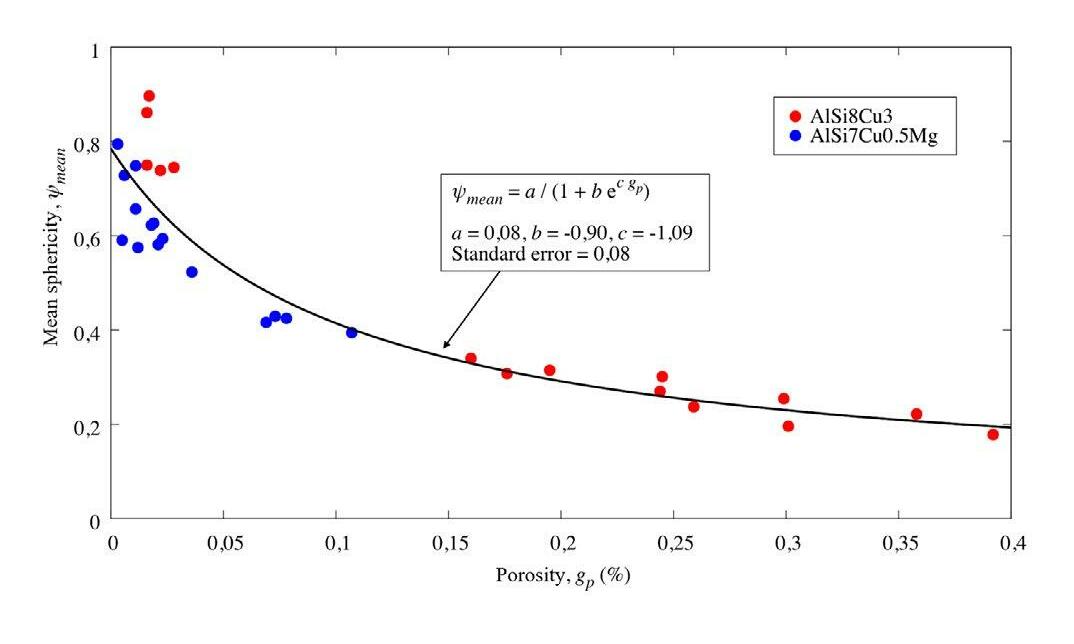
Figure 3: Plot of maximum envelope diameter plotted against porosity [5]. Figure 4: Plot of volume-weighted mean sphericity versus porosity
图3:最大包络体直径-孔隙度的关系图[5] 图4:加权体积平均球形度与孔隙度的关系图
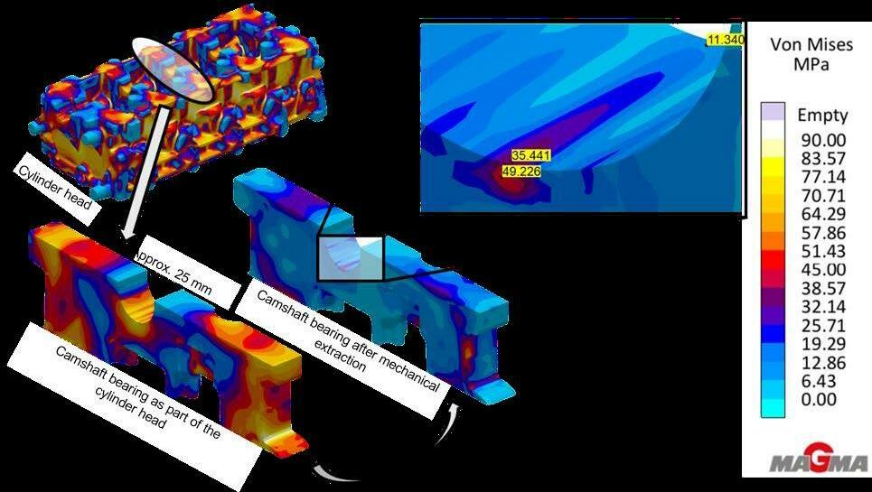
Figure 5: Representation of the simulated Von Mises equivalent stress after T6W heat-treatment of the entire cylinder head (top left), in the camshaft bearing as part of the cylinder head (bottom left) and after mechanical extraction of the camshaft bearing for the validation tests (center)
图5:T6W热处理后的整个缸盖(左上)、作为缸盖一部分的凸轮轴轴承(左下)和凸轮轴轴承机械提取后 (中间)的模拟Von Mises等效应力
probably limited to melt of low gas content (in the case of aluminum casting alloys low hydrogen). In the case of the specimens presented in this work, pore formation can be assumed to occur very late in the solidification process. The dendritic microstructure thus has a strong impact on the development of the pore shape. 6. Residual Stress Distribution after Heat Treatment
The casting process and heat treatment of aluminum castings can lead to significant residual stresses. Since these residual stresses can have both beneficial and detrimental effects on the loads that can be borne when the component is used, they must be taken into account already during the component design. If disadvantageous stress conditions cannot be avoided due to the part design, sensible adjustments (geometry, quenching process after solution annealing) can already be made at this stage. For the AlSi7Cu0.5Mg cylinder head, the residual stresses were calculated based on its T6W heat treatment (water quenched) using MAGMASOFT® [A]. MAGMASOFT® can also be used to account for the stress redistributions resulting from cutting a sample from the cylinder head. The result is shown in Figure 5.
After heat treatment, significant residual stresses are
而降低的形式显示了这一点。这种球形度的降低是由 于枝晶状微观组织对正在长达的缩孔的生长限制增加 所致。存在的缩孔数量越高,最大的缩孔变得越褶皱。 进一步的分析 [10] 表明,这种行为不一定是这种情况, 但可能仅限于低气体含量的熔体(在铝合金铸造合金 低氢的情况下)。在这项工作中介绍的样本的情况下, 可以假设孔隙形成发生在凝固过程的后期。因此,枝 晶状微观组织对缩孔形状的发展具有强烈的影响。
6. 热处理后的残余应力分布
铝合金铸件的铸造工艺和热处理会产生明显的残 余应力。因为这些残余应力对部件服役期间承受的载 荷有利有弊,因在部件设计过程中就要考虑这些残余 应力。如果由于零件设计无法避免不利的应力条件, 则可以在此阶段进行合理的调整(几何形状、固溶退 火后的淬火工艺)。对于AlSi7Cu0.5Mg气缸盖, 残余应力是基于使用MAGMASOFT ® [A]的T6W 热处理(水淬)计算的。MAGMASOFT ® 也可用于 计算从缸盖上切割样品导致的应力重新分布。结果如 图5所示。
present in the casting. With a Von Mises equivalent stress of more than 90 MPa in case of the T6W treatment, these must be taken into account in a fatigue simulation. The main cause of the high stresses is the different cooling rates during water quenching after solution heat treatment (T6W). The mechanical removal of the camshaft bearing samples for the validation tests from the heat-treated cylinder heads results in the redistribution of the residual stresses. This process involves cutting the specimen region clear from the overall cylinder head and then calculating a new mechanical equilibrium in the specimen. The result is a changed stress state with asymmetrical stress distribution in the notch area. The Von Mises stress reaches values of up to approx. 50 MPa, see Fig. 5.
7. Estimation of Local Fatigue Strength Using the Example of the Camshaft Bearing
It is common practice to predict the local dendrite arm spacing (DAS) from the local solidification time. This in turn can be simply correlated with the tensile strength. In die casting the DAS, via the local cooling rate, is strongly controlled by the respective distance to the mold wall. As the distance from the mold surface increases, the DAS in the camshaft bearing increases. Simple correlations can therefore be used to predict the local tensile strength (Rm) using tensile tests for known values of the DAS. The tensile strength can be used for improved estimation of cyclic properties through established approaches. It becomes clear that this approach only takes into account the local solidification rate. Local changes in thermal gradient, alloy-specific solidification morphology, or microporosity do not affect the predicted fatigue properties. Thus, while
热处理后,铸件中存在大量的残余应力。在 T6W处理的情况下,Von Mises等效应力超过 90MPa,在疲劳模拟中必须考虑这些残余应力。高 应力的主要原因是固溶热处理(T6W)后水淬过程中 不同的冷却速度。凸轮轴轴承样品从经过热处理的缸 盖上机械去除会导致残余应力的重新分布。该过程 包括从整个缸盖上切下试样,然后计算试样中的新 机械平衡。缺口区域中具有不对称应力分布。Von Mises应力值高达约50MPa,见图5。
7. 以凸轮轴轴承为例估算局部疲劳强度
局部枝晶间距(DAS)通常是根据凝固时间预测 的,然后简单的跟拉伸强度对应起来。在压铸过程中, DAS(通过局部冷却速率)受到与模具壁的相应距离 的控制。随着与模具表面距离的增加,凸轮轴轴承中 的DAS增加。因此,使用已知DAS值的拉伸试验, 可以使用简单的相关性来预测局部拉伸强度(Rm)。 通过已建立的方法,拉伸强度可用于改善对循环特性 的估计。很明显,这种方法只考虑了局部凝固速率。 热梯度、合金特定凝固形貌或微观缩孔的局部变化不 会影响预测的疲劳性能。因此,虽然与恒定的材料特 性相比,这种方法可以改进组件设计,但它并没有考 虑到局部效应。预期和观察到的失效行为之间的显著 偏差仍然存在。 通过考虑局部微观缩孔,从而根据孔包络的最大 直径考虑局部存在的缺陷尺寸,可以显著扩展上述方
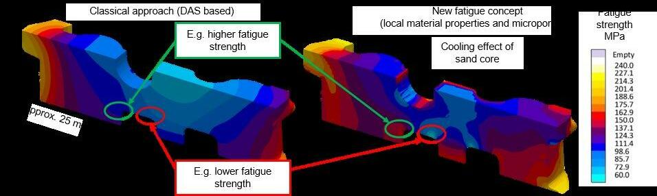
Figure 6: Plot of the tension-compressive fatigue strength in section through the center of the camshaft bearing using the "classical" approach, based on the local DAS (left), as well as based on the additionally included microporosity prediction and the derived defect size (right)
图6:基于局部DAS使用“经典”方法绘制的拉伸-压缩疲劳强度图(左), 以及考虑包括微孔预测和衍生 缺而绘制的拉伸-压缩疲劳强度图(右)
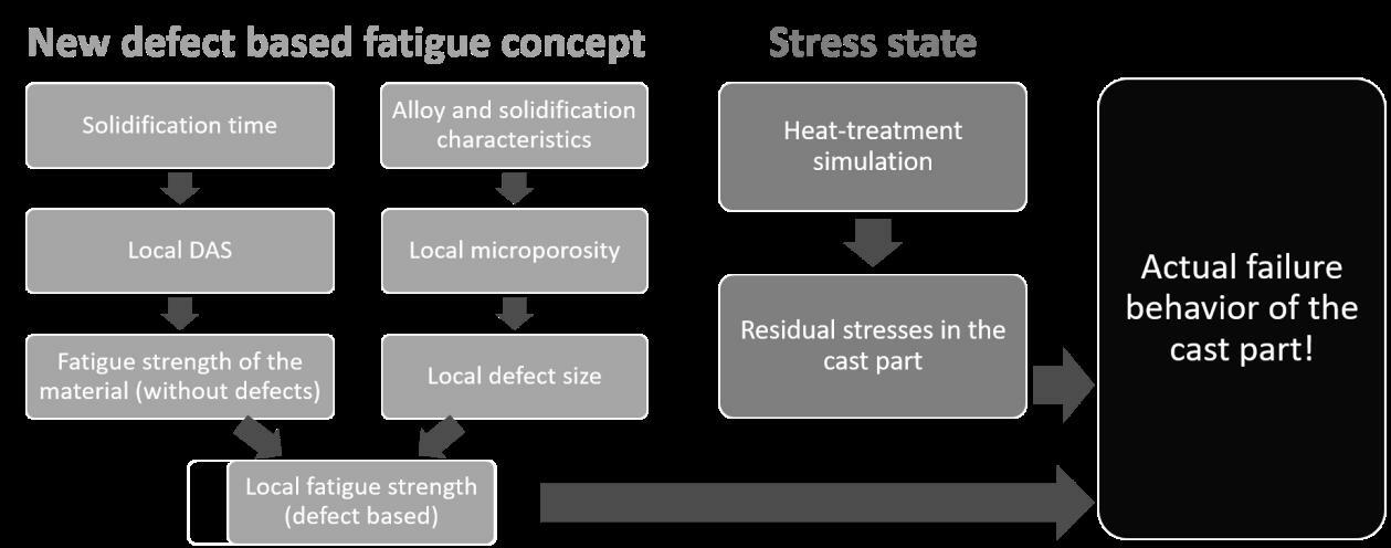
Figure 7: Presentation of the newly developed concept for predicting the actual failure behavior of aluminum castings
图7:用于预测铝铸件实际失效行为的新开发概念的介绍
this approach leads to improved component design compared to constant material properties, it does not account for local effects. Significant deviations between the expected and the observed failure behavior do remain.
By considering the local microporosity and thus the locally present defect size in terms of the maximum diameter of the pore envelopes, the above approach can be significantly extended. For the prediction of local microporosity, several different models are described in the literature. In this work, reference is made to the publication by Carlson et al. [11], which was used to predict the local amount of microporosity for the camshaft region of the cylinder head. Even though a very low porosity level prevails in most areas, significantly higher local microporosity levels are also evident, some of which exceed the investigated test space. Therefore, the predicted porosity level was limited to 0.5% by volume.
The defect size and microstructure characteristics allow the prediction of the local cyclic fatigue properties[12]. Figure 6 shows a comparison of the fatigue strength in tension-compression loading calculated by MAGMASOFT® in the center of the camshaft bearing. The classical approach considering only the DAS (left) shows the effect of the decreasing cooling rate from the die to the thermal center in the middle of the casting. Only by including the microporosity (right) are local effects taken into account, such as the reduction of microporosity near the sand core as well as the effect of a large thermal gradient.
To prove the suitability of the explained concept, the Institute for General Mechanical Engineering in
法。对于局部微观缩孔的预测,文献中描述了几种不 同的模型。在这项工作中,参考了Carlson等人的 论文,用于预测缸盖凸轮轴区域的局部微观缩孔的数 量。尽管在大多数区域普遍存在非常低的孔隙度水平, 但局部微孔隙度水平也明显较高,其中一些超过了所 研究的测试空间。因此,预测的孔隙度水平限制在 0.5%(按体积计)。 缺陷尺寸和微观组织特征允许预测局部循环 疲劳特性 [12] 。图6显示了在凸轮轴轴承中心由 MAGMASOFT ® 计算的拉伸-压缩载荷下的疲劳强 度的对比。仅考虑DAS(左)的经典方法显示了从 模具到铸件的热中心的冷却速率降低的影响。只有包 括微观缩孔(右)才能考虑局部效应,例如砂芯附近 微观缩孔的减少以及大热梯度的影响。 为了证明所解释概念的适用性,位于奥地利莱奥 本的通用机械工程研究所对凸轮轴轴承进行了验证测 试。同样,AVL List 公司使用FEMFAT软件模拟 了失效行为。FEMFAT中使用的所有局部机械性能 以及残余应力均使用MAGMAlink模块进行传输。 图7再次总结了新开发的预测铝铸件实际失效行为的 方法:只有通过考虑包括局部存在的微观缩孔以及铸 造和热处理过程中的残余应力,才能真实地预测部件 行为。 图8显示了凸轮轴轴承样品的验证测试结果。在 测试条件下将性能(拉伸-压缩疲劳强度和残余应力 状态)转移到FE网格。如果不考虑局部材料性能和
Leoben, Austria, conducted validation tests for the camshaft bearing. Similarly, AVL List GmbH simulated the failure behavior using the FEMFAT software. All local mechanical properties used in FEMFAT, as well as the existing residual stresses, were transferred using the MAGMAlink module. Figure 7 summarizes again the newly developed approach for predicting the actual failure behavior of an aluminum casting: The component behavior is predicted realistically only by including the locally present microporosity as well as the residual stresses from the casting and heat-treatment process.
Figure 8 shows the results of the validation tests with the camshaft bearing samples. The properties (tensioncompression fatigue strength and residual stress state) were transferred to the FE mesh in the test condition. Without taking local material properties and residual stresses into account, a realistic prediction of the failure behavior is not possible.
If only residual stresses combined with homogeneous material properties are taken into account, the vibration resistance is overestimated (Fig. 8 yellow data series). The same is true if the DAS without residual stresses is considered (Fig. 8 green data series). Compared to the first case (yellow data series) the deviation between the real tests and the simulation is smaller. Only by considering both factors, i.e. the local residual stress state and the local property distribution, the observed cyclic component behavior can be satisfactorily predicted (Fig. 8 red data series). 8. Summary and Conclusion
In the course of a comprehensive analysis of microporosity in cylinder heads for two typical casting alloys, a correlation between the characteristic pore size, pore shape, and the overall porosity of the samples was determined. In this process, the sphericity of the pores decreases continuously, whereas the maximum pore dimensions increase with increasing porosity. Both dependencies are directly related to the mechanisms of pore formation in a dendritic microstructure, which determines both the pore shape and the pore size. The determined relationship was used to predict a porositybased fatigue strength. In addition to the cooling rate, this allows both the local feeding properties and the specific solidification characteristics of the alloy to be taken into account; thus significantly improving the local prediction of the cyclic fatigue strength of the component. Furthermore, the residual stress state after T6W heat- treatment was considered. With the help of validation tests, it could be demonstrated that the local fatigue strength, as well as the residual stress state, are necessary to achieve a satisfactory accuracy in the prediction of the failure behavior. The developed methodology thus represents a significant extension of previously used methods for the design of highly loaded cast components. The targeted use of this approach in the context of virtual designs of experiments (DoE)
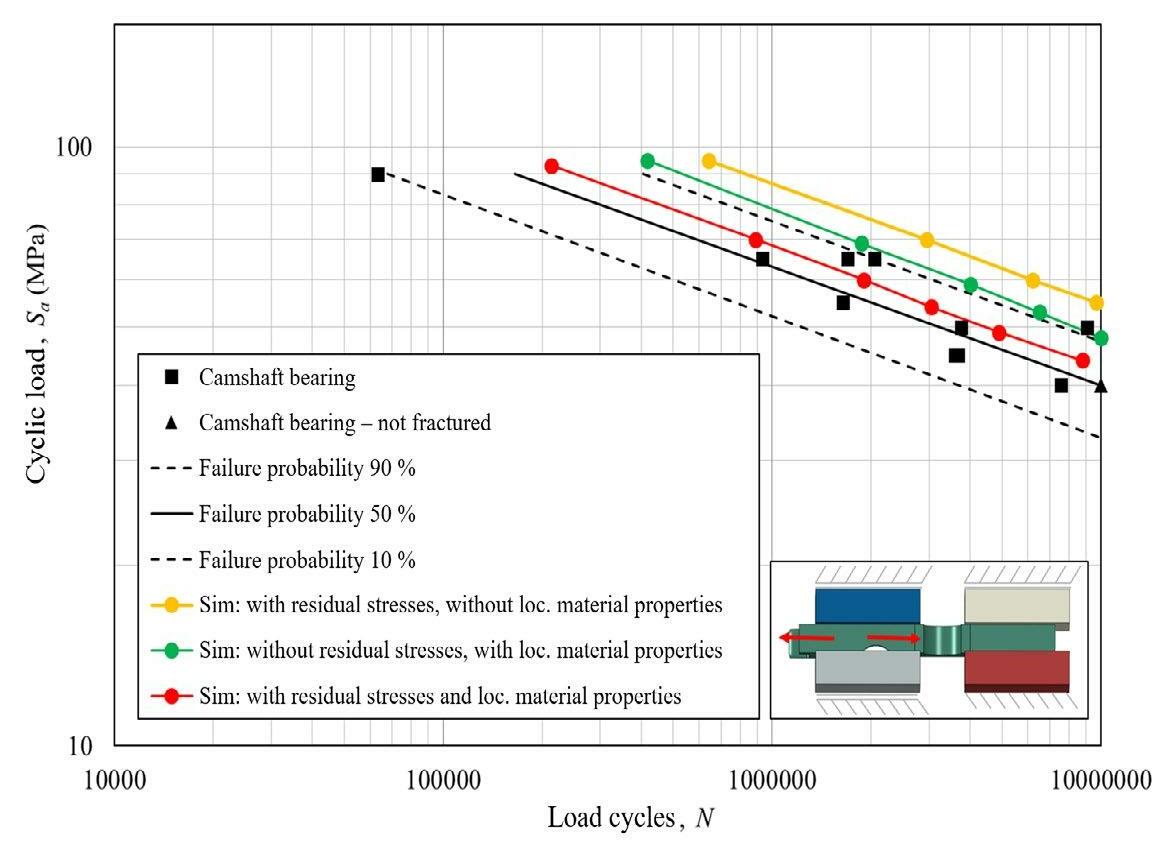
Figure 8: Result of the tension-compressive fatigue test of the cylinder head camshaft bearing samples (R = -1) of the alloy AlSi7Cu0.5Mg (T6W) [13]
图8:合金AlSi7Cu0.5Mg (T6W)的缸盖凸轮轴轴承样品(R =-1) 的拉压疲劳试验结果[13]
残余应力,就不可能对失效行为进行真实的预测。 如果仅考虑残余应力和均质材料特性,则抗振性 被高估(图8黄色数据系列)。如果考虑没有残余应 力的DAS,情况也是如此(图8绿色数据系列)。 与第一种情况(黄色数据系列)相比,真实测试与模 拟之间的偏差更小。只有考虑局部残余应力状态和局 部性能分布这两个因素,才能令人满意地预测观察到 的循环分量行为(图8红色数据系列) 。
8.总结与结论
在对两种典型铸造合金的气缸盖微观缩孔进行综 合分析的过程中,确定了样品中的特征缩孔尺寸、 缩孔形状和总孔隙率之间的相关性。在这个过程中, 孔隙的球形度不断减小,而最大孔隙尺寸随着孔隙 率的增加而增加。这两种依赖性都与树枝状微结构 中的孔形成机制直接相关,这决定了孔的形状和孔 径。以上可用于预测基于孔隙率的疲劳强度。除了 冷却速度之外,这还允许考虑合金的局部进给特性 和特定的凝固特性;从而显著提高了部件循环疲劳 强度的局部预测。此外,考虑了T6W热处理后的残 余应力状态。在验证测试的帮助下,可以证明局部 疲劳强度以及残余应力状态对于在预测失效行为方 面达到令人满意的准确性是必要的。因此,所开发
promises a precise development of components as well as their robust production in the real casting process.
9. Acknowledgments
The authors would like to thank Nemak Linz for providing the castings and AVL List GmbH for the simulations of the validation samples. Thanks also go to Materials Center Leoben GmbH for performing the CT scans and to the Chair of General Mechanical Engineering at the University of Leoben, which developed the failure model and performed the validation tests. Work carried out by the Chair was financially supported by Austrian governmental institutions within the framework of the COMET funding program ("Integration of casting simulation into the operationally stable component design of cast aluminum components", COMET K2, Project A1.20). ■
的方法是以前用于设计高负载铸造部件的方法的重 要扩展。在虚拟实验设计 (DoE) 的背景下有针对性 地使用这种方法保证了组件的精确开发以及它们在 实际铸造过程中的稳健生产。
9.致谢
感谢Nemak Linz提供铸件,感谢AVL List 公司提供验证样品的模拟。还要感谢Leoben公司 材料中心进行CT扫描,感谢Leoben大学通用机械 工程系主任,他开发了失效模型并进行了验证测试。 主持开展的工作得到了奥地利政府机构在COMET 资助计划(“将铸造模拟集成到铸铝部件的运行稳定 部件设计中”,COMET K2,项目A1.20)框架内 的财政支持。 ■
PRODUCT NEWS / 产品新闻 Product News Table of Contents 产品新闻目录
MOLD, CORE & SAND PREPARATION
造型、制芯&砂处理
Omega Foundry Launch New Product-Portable, Compact & Powerful 50 Omega 铸造发布新产品——便携、紧凑且功能强大
10 Million Moulds in under 5 Years: Disamatic C3-350 Delivers Incredible Uptime with High Quality andLow Maintenance 53 5 年内超1000 万型:高质量和低维护成本的 DISAMATIC C3-350 的超预期正常运行时间 SOFTWARE
软件
Calderys Removes the Stress of Bentonite Stock Management with Calde® E-Supply
凯得力公司推出 Calde® 电子供应系统消除膨润土库存管理 的压力 51
PRODUCT NEWS / 产品新闻 Omega Foundry Launch New Product-Portable, Compact & Powerful Omega铸造发布新产品——便携、紧凑且功能强大
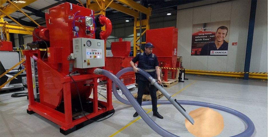
The Omega Foundry Vac is the latest product to join the Omega equipment portofolio. This is the perfect foundry accessory with a suction conveying unit suitablefor most sands, shot, powders, granular products and metal slag. The Vac handles up to 10 tonnes per hour of dry sand, based on 10 metre hose with bulk densities of material approx. 1600 (kg/m3) and it is effective over distances up to 30m. Features:
·Easily handled with a fork lift truck, the Foundry Vac weighs less than 2000kg. ·Robust design for foundry environment. ·750 litre capacity removable hopper for material collection. ·Simple operation with self cleaning cycle. ·Range of hose sizes & accessories to suit application (easily interchanged)..
The surface finish of our castings is very smooth with almoWe have a Demo Unit at our headquarters, in Peterborough, so don't take our word for it, come and try it! Contact sales@ofml.net/spares@ofml.net to book your trial or to ask for further information about the Omega Foundry Vac. ■
Omega Foundry Vac是加入Omega设备组合的 最新产品。这是完美的铸造厂辅助设备,带有适用于大 多数砂、丸、粉末、粒状产品和金属废料的抽吸输送装 置。通过10米长的软管,Vac每小时可处理多达10吨 的干砂,材料体积密度约为1600kg/m3,有效距离可达 30m。
产品特点:
·使用叉车轻松搬运,Foundry Vac重量不到 2000kg; ·针对铸造环境的稳健设计; ·750L容量可拆卸料斗,用于物料收集; ·操作简单,自清洁循环; ·适合应用的软管尺寸和配件范围(易于互换)。我 们在彼得伯勒的总部有一台演示设备,所以不要只听 我们所说的,快来试验吧!请联系sales@ofml.net 或spares@ofml.net预订您的试用版或获得更多信 息。 ■
CALDE® e-Supply takes over the monitoring and ordering of bulk materials, ensuring foundries never run out of critical supplies, while freeing up operators to focus on more important tasks.
Ensuring consistent supply of bentonite is a crucial element of foundry management. Simply put: you don’t want to run short.
However, keeping track of bentonite consumption and supply can be complex. This is particularly so at larger foundries, which might receive multiple deliveries a week to keep up with demand, at foundries with limited bentonite storage capacity, or at foundries serving the automotive sector, where even the slightest delay is unacceptable.
Automazing the bentonite management
Supporting foundries at potential pain points and helping to improve the ease of doing business is one of the main aims of the digital innovation strategy at Calderys. The company has spent significant time understanding what these pain points are and developing a product development pathway that aligns with them. It’s a customer-centric approach that enables the company to offer solutions that make a tangible difference to foundries’ day-to-day operations.
One of the solutions that has resulted from this approach is the CALDE® e-Supply stock management system. Volumetric sensors installed inside the silo keep track of stock levels. These data are sent to the e-Supply software platform, which combines them with other factors, such as silo capacity, historic usage rates and the distance from a Calderys supply center, to determine when a new shipment of material will be needed. At this point, the system will create and send Calderys an automated order.
Maximilian Eilhard, Account Manager Metallurgy at Calderys, explains: “CALDE® e-Supply is an example of a vendor-managed inventory (VMI) system. These have long been used in the foundry industry to manage stocks of various process gases, such as hydrogen and oxygen.
“We have simply taken this well-known concept and applied it to manage bulk material supplies, such as bentonite and bentonite premixes, to prevent stock shortfalls and emergency orders.” Foundries are therefore assured of proper and demand-based material planning, continued Eilhard.
Calde® 电子供应系统可以执行散装材料的监控和订 购,确保铸造厂永远不会出现关键供应断供现象,同时能 够让作业人员专注于更重要的工作。 确保膨润土的持续供应是铸造厂管理的关键要素。简 单地说,不能出现短缺。 然而,跟踪膨润土的消耗和供应非常复杂,在较大的 铸造厂更是如此。这样的情况,在膨润土储存能力有限的 铸造厂,或者在服务于汽车行业的铸造厂,即使是最轻微 的延迟都是不可接受的。
膨润土供应自动化管理
支持铸造厂解决潜在的痛点和助力提高业务的便利性 是加州大学数字创新战略的主要目标之一。该公司花费大 量时间了解这些痛点,并开发了与之一致的产品开发途径。 这是一种以客户为中心的方法,使公司能够提供解决方案, 对铸造厂的日常运营产生切实的影响。 这种方法产生的解决方案之一是 Calde® 电子供应 库存管理系统。安装在筒仓内的体积传感器可以跟踪 库存水平。这些数据被发送到电子供应软件平台,该 平台将其与其他因素相结合,如筒仓容量、历史使用 率和距凯得力公司供应中心的距离,以确定何时需要 新的材料。此时,系统将创建并自动发送订单。 凯得力公司冶金客户经理马克西兰·艾哈德解释 说:“Calde® 电子供应是供应商管理的库存(VMI)系 统的一个例子。这些系统长期以来在铸造行业被用于 管理各种工艺气体的库存,如氢气和氧气。 “我们只是采用了这个众所周知的概念,并将其 应用于管理散装材料的供应,如膨润土和膨润土预混 料,以防止库存短缺和紧急订单。”因此,铸造厂保 证适当的和基于需求的材料计划,艾哈德说。 “有了 Calde® 电子供应系统,再也不会出现紧急 的订单。它还消除了向凯得力公司发送订单时出现的 人为错误,因为系统直接连接到我们的ERP系统并
“With CALDE® e-Supply, there are no more rush orders. It also eliminates the potential for human error creeping in when sending orders to Calderys, as the system is connected directly into our ERP system and runs automatically.” CALDE®e-Supply: a simple implementation process
Installation at the customer site is relatively straightforward. In the first step, a technical audit is undertaken to establish whether there are any existing silo monitoring sensors on site and, if so, whether the output from those systems can be integrated with e-Supply. If no sensors are present or if they are unable to be integrated with e-Supply, new sensors are installed in the silos.
The sensors are then connected to an outstation box, installed close to the silo, which takes the sensor outputs and sends them to e-Supply’s web-based interface. Here, they can be viewed by foundry personnel at any time, from anywhere, via mobile devices, as well as on traditional desktop systems.
“We generally start running CALDE® e-Supply in parallel with the foundry’s traditional bentonite management system, with the customer continuing to place orders,” said Eilhard. “When we have established that the system works and is running well – building up the trust of the foundry operators – we let CALDE®e-Supply take over the ordering.” Technology at the service of productivity
Pilot trials of CALDE® at Olsberg GmbH and Miele & Cie. KG have proven successful, with the technology now rolled out at further foundries.
Implementation at Olsberg GmbH was a particular test for the CALDE® e-Supply system. Located in North RheinWestphalia, Germany, the company produces series and hand-formed, core-intensive iron castings. The key challenge, however, was the site’s low silo capacities for bentonite and a bentonite-coal dust premix: just 37 tonnes and 31 tonnes, respectively.
“There’s not much capacity at Olsberg GmbH to add new shipments, which come in 25-tonne loads,” explained Eilhard. “The foundry has to run the silo level down quite low before it can take new shipments. To determine at what point an automatic product order should be generated, CALDE® e-Supply must ensure the silos have capacity to take delivery of the load, but sufficient remaining stock in the meantime to make sure the foundry doesn’t run short.”
Despite the challenge, CALDE®e-Supply has been successfully implemented at Olsberg GmbH, providing peace of mind at a previous pain point. And as the foundry’s general manager pointed out, “if the CALDE® e-Supply systems work at our plant, it will work anywhere”.
“The ultimate benefit of e-Supply is time,” concluded Eilhard. “Customers no longer need to spend time managing and worrying about stocks of bentonite and other bulk materials, so they can focus elsewhere, on more critical tasks.” ■
自动运行。”
Calde® 电子供应系统:简单的实现进程
在客户现场的安装相对简单。第一步,先进行技 术审计,以确定现场是否存在任何现有的筒仓监测传 感器,如果有,这些系统的输出是否可以与电子供应 集成。如果没有传感器或无法与电子电源集成,则会 在筒仓中安装新的传感器。 然后,传感器被连接到仪表外站箱,安装在筒仓 附近,它接收传感器的输出,并将其发送到电子供应 的网络界面。在这里,铸造厂的工作人员可以在任何 时间、从任何地方、通过移动设备以及在传统的桌面 系统上查看它们。 艾哈德说:“我们通常在与铸造厂传统的膨润土 管理系统的同时运行 Calde® 电子供应系统,客户继 续下订单。当我们确定系统工作和运行良好——建立 铸造运营商的信任——我们让 Calde® 电子供应 系统
接管订购。”
技术服务于生产力
Calde® 电子供应系统在奥尔斯堡公司和Miele & Cie. KG公司的试点试验已经证明是成功的,目前该 技术已进一步在铸造厂推广。 在奥尔斯堡公司的实施是对 Calde® 电子供应系统 的特殊测试。该公司位于德国北莱茵-威斯特法伦州, 手工造型方式生产系列多芯的铸铁件。然而,关键的 挑战是该公司的膨润土和膨润土-煤粉预混料的筒仓 容量低:分别只有37t和31t。 “奥尔斯堡公司的筒仓没有足够的空间接受新的 散装料,每次运输的散装料为25t。” 艾哈德解释说, “铸造厂只有在筒仓料位很低时,才能接收新的材料。 为了确定在什么时候应该自动发送产品订单,Calde® 电子供应系统必须确保筒仓有空间接收新材料,但在 此期间须有足够的剩余库存,以确保铸造厂不会短 缺。” 尽管面临挑战,Calde® 电子供应已经在奥尔斯堡 公司成功实施,解决了之前的痛点问题。正如铸造厂 总经理指出的,“如果 Calde® 电子供应系统在能够 在我们的工厂运行,它将能够任何工厂工作。” “电子供应的最大好处是及时,”艾哈德总结道, “客户不再需要花时间管理和担心膨润土和其他散装 材料的库存,所以他们可以集中精力在其他地方,完 成更关键的任务。” ■
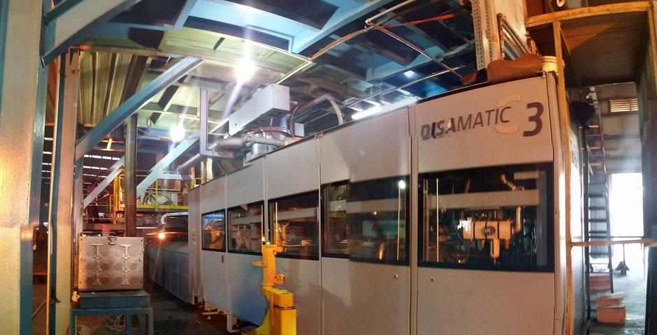
PRODUCT NEWS / 产品新闻 10 Million Moulds in under 5 Years: Disamatic C3-350 Delivers Incredible Uptime with High Quality and Low Maintenance 5年内超1000万型:高质量和低维护成本的 DISAMATIC C3-350的超预期正常运行时间
Since Chinese foundry Guangzhou Deshan CNC Technology Co. Ltd. installed its first DISAMATIC C3-350 machine in December 2017, this green sand, vertical moulding line has produced more than 10 million moulds. The moulding machine runs 24/7 and produces an average of over 7,000 moulds every day.
With a 1.2% scrap rate, the DISA machine adds outstanding quality and high uptime to its blazing speed. The line is incredibly low maintenance, freeing up over 2 hours extra production time per day compared to the foundry’s previous moulding machine supplied by a DISA competitor.
Impressed by its performance and reliability, Guangzhou Deshan is about to buy another DISAMATIC C3 to expand its annual production capacity to 30,000 tons and beyond.
“DISAMATICs are famous for combining speed with consistent high quality and uptime,” says Leon Gu, VP After Sales at DISA Asia Pacific. “The DISAMATIC C3 is purposebuilt to offer lower-volume foundries a big speed and quality boost. It produces small series or lower volumes economically and, on top of that, is an affordable, China-built machine
自从中国广州德善数控科技有限公司(以下简称广 州德善)于2017年12月安装了第一条DISAMATIC C3-350造型线起,这条黏土砂垂直造型线至今已生产了 1000多万个铸型。造型线24小时运行,平均每天生产超 过7,000铸型。 与迪砂设备相关的废品率仅为1.2%,极快的造型速 度匹配卓越的铸件品质和更长的正常运行时间。该生产线 的维护成本极低,这与之前使用的其他品牌造型机相比, 每天可多出至少2小时的额外稳定生产时间。
基于迪砂造型线的卓越性能和高可靠性给人留下了深 刻的印象,广州德善计划购买另一条DISAMATIC C3造 型线,将其年产能扩大到30,000t或更大。 “DISAMATIC垂直造型线以造型速度与始终如一的 高质量和正常运行时间相结合而闻名,”迪砂亚太区售后 副总裁顾琳俊说到。“DISAMATIC C3是专为中小铸造
that DISA can supply quickly to the Chinese market with outstanding local service and spares support.” Low maintenance, genuine parts give 2 hours extra production
Guangzhou Deshan was founded in 2001 and is based in Nansha Guangzhou city, Guangdong province. Before installing the DISAMATIC C3-350, the foundry ran a slower moulding line from a Chinese competitor which had to be maintained and repaired for 2.5 hours every day, losing valuable production time. In contrast, the DISAMATIC C3-350 only needs around 20 minutes daily maintenance.
“The DISAMATIC C3 is very durable and is also very simple to maintain,” says Michael Yin, Service Manager at DISA Asia Pacific. “Guangzhou Deshan has also chosen to only fit original DISA spare parts. Because these OEM parts fit perfectly and have longer lifetimes, that means less planned and unplanned downtime. In the end, that gives the foundry the lowest running costs.” Speed plus quality, made in China
Available in three speeds (up to 350 uncored moulds per hour) and in a range of sizes, the DISAMATIC C3 can produce a wide variety of grey iron, ductile iron and other metal castings. The two faster models can be fitted with an optional automatic coresetter. The DISAMATIC C3 offers maximum performance for minimum investment, and a high ROI over a long service life.
“The DISAMATIC C3 uses advanced vertical moulding technology that easily outperforms its competitors but it is also flexible and cost-effective,” says Mr Gu. “It’s the clever choice for foundries that want to grow quickly.”
For more information on the DISAMATIC C3, please visit: https://www.disagroup.com/en-gb/foundry-products/ moulding-solutions/disamatic/disamatic-c-lines. ■
厂提升铸件质量同时提高生 产效率而研发的产品。这个 来自中国制造的设备提供更 经济、更灵活的生产方式, 同时降低每一个铸件的生产 成本,迪砂可以通过出色的 本地服务和备件支持快速向 中国市场供应。”
低维护需求,原装零件 提供2小时的额外生产 时间
广州德善成立于 2001年,总部位于广东 省广州市南沙区。在安装 DISAMATIC C3-350之前,该铸造厂运行的是一条 来自其他品牌的造型线,该生产线每天至少花费2.5小 时在保养维护上,从而浪费了宝贵的生产时间。相比之 下,DISAMATIC C3-350每天仅需约20分钟的维护 时间。 “DISAMATIC C3非常耐用,维护起来也非常简
单,”迪砂亚太区服务经理尹国明说到。“广州德善坚持
选择使用迪砂的原厂备件。由于这些原厂备件可与设备完
美匹配且使用寿命更长,这意味着可以同时减少计划内和
计划外的停机时间。最终,这使得德善得运行成本持续降
低。”
速度加品质,中国制造
DISAMATIC C3系列有三种造型速度(每小时多达 350个不下芯铸型)和各种型板尺寸可选,可生产各种灰铁、 球墨铸铁和其他金属铸件。两款速度更快的型号可选配自动 下芯机。DISAMATIC C3以最少的投资提供最高性能,并 在较长的使用寿命内提供高投资回报率。 顾先生说:“DISAMATIC C3采用最为先进的垂 直造型技术,使您轻松超越竞争对手,灵活经济、提升 效益。“对于希望快速发展的铸造厂来说,这是一个明 智的选择。 更多关于DISAMATIC C3的信息,请访问网 站:https://www.disagroup.com/en-gb/foundryproducts/moulding-solutions/disamatic/disamaticc-lines ■