Selected Project of Hsuan-Hui, Fu. 2018-2023
Love that is first and last of all things made, The light that moving has man's life shade.
Kindergartan and an Intersect Pavilion Acadamic Work
Taichung suburbs, Taiwan
Tutor : Wun-Ying, Huang
Parish with a basketball court Revisit Work
Taichung city center, Taiwan
Tutor : -

Kindergartan and an Intersect Pavilion
The pavilion and kindergarten in this design are located in the Shanshui community, a small rural area with a mix of agriculture and industry on the west side of Taichung. The kindergarten serves as an extension of the teaching area, while the pavilion consolidates the community's public spaces.
Within a simple rectangular framework, a circle close to the ground and a line angled off are placed. The pavilion utilizes geometric relationships to disperse and converge the temple square, entrance, and teaching area. The kindergarten, positioned vertically within the existing school campus, incorporates circles and squares on the roof volume as part of the circulation, while leaving a courtyard. The axis between the kindergarten and the temple square forms a triangular outdoor activity area, with the acute angle serving as both the entrance to the kindergarten and corresponding to the community space.
The clear system is inserted into the texture-rich community, evoking strong and heterogeneous sensations. The new architecture seamlessly integrates with the existing spaces, establishing a place of continuity and memory.


 Kindergartan and an Intersect Pavilion
The Shanshui community, like many rural areas in Taiwan, is a mix of agriculture and industry. From afar, layers of boundary relationships are visible, with the community's skyline formed by factory walls. The arranged rice fields serve as transition zones between the two, with water channels flowing through the fields into the community, separating it from the rice paddies. The community itself is divided into individual households by walls. While interconnected, each element remains distinct, forming tight-knit connections. The pavilion and kindergarten have a strong intention to make this interconnectedness more conscious.
By integrating into the existing structural arrangement of the campus, the pavilion and kindergarten roofs placed atop the mountain walls introduce different geometric forms, offering new sensations while responding to the scale relationship between children and adults. The mountain-wall roofs can also be seen as a transformation of rural spatial vocabulary.


Red geometric form makes the space more significant. Structure as a hint of axis, following the trace of the school yard. Playground elements become fragments of the previous structure and transforming into street furniture.


The scale change along the sloping roof, two usage scenarios appeared with the flow. And the triangular space creates a playing corner only for school children.


The new Pavilion corresponds to the column spacing of the existing auditorium on the campus, and the kindergarten continues to do so.


 Kindergartan and an Intersect Pavilion


The topic is set to add a custom composite functional space to a religious architecture without commercial activities, which corresponds to the existing old buildings and constantly updated consumption patterns in front of the train station, and the complex form of the base.
I chose my mother's faith, Catholicism.
In addition to the church, the diocese has built an open space with a scaffolding, which will be used as an outdoor church to accommodate more parishioners for worship on certain holidays, such as Easter, Christmas, Palm Sunday, etc., and flexible space for activities the rest of the time. Therefore, I set the additional functional space of the church as a stadium, so that the space can be flexible in terms of function and number of users. The huge volume of the stadium and the indented front yard, with the surrounding street houses and advertising signs, pull out the contrast between the scale and the definition. The ordinary spatial function is combined with a clear volume, and the religious space is clearly described, and at the same time, it is commemorative and accessible.

 Parish with a Basketball Court


The height of the whole volume is lower than that of the adjacent houses of the three floors, and it is separated from other buildings on the overall façade.
The façade is concise, but the entrance is conspicuous. Due to the low floor and high building, the southwestfacing alleyway has higher light transmittance and is more open.


 Parish with a Basketball Court
The beams and the arches of the roof are embedded and support each other, transmitting force to the columns and the thick walls in the church, so that the entire structural system is interlocking.
The church has three steps at the front and back of the seats, as a hint of spatial transformation. A straight staircase leads from the largest pitch to the compressed basement to the sacred church.


Orthogonal Co-living House Revisiting Work
Taichung Feng Chia, Taiwan
Tutor : -
Therme and Bridge Diploma Project
Nantou Xin Yi, Taiwan
Tutor : Cheng-Hsuan Wu
The site of this topic is based on the proximity to the Feng Chia Night Market, which has a very high housing density. With co-living as the main axis, discussed the possibility of a small housing.
I try to divide the space geometrically with the rotation of the orthogonal system, rather than dividing it with walls, so that the public space is connected by users. Maintaining privacy in a relatively small scale, but at the same time opening up with an appropriate degree of openness.
The residential units are arranged in the corners, and the room types have equal lighting, so that each user is equal in space.The configuration of double and single room types to meet different needs. The size of the void and the direction of the opening distinguish the noisy space with high activity from the more static activity space.
Orthogonal Co-living House ,Dong Pu,Taiwan 2023 Orthogonal Co-living House
 Orthogonal Co-living House
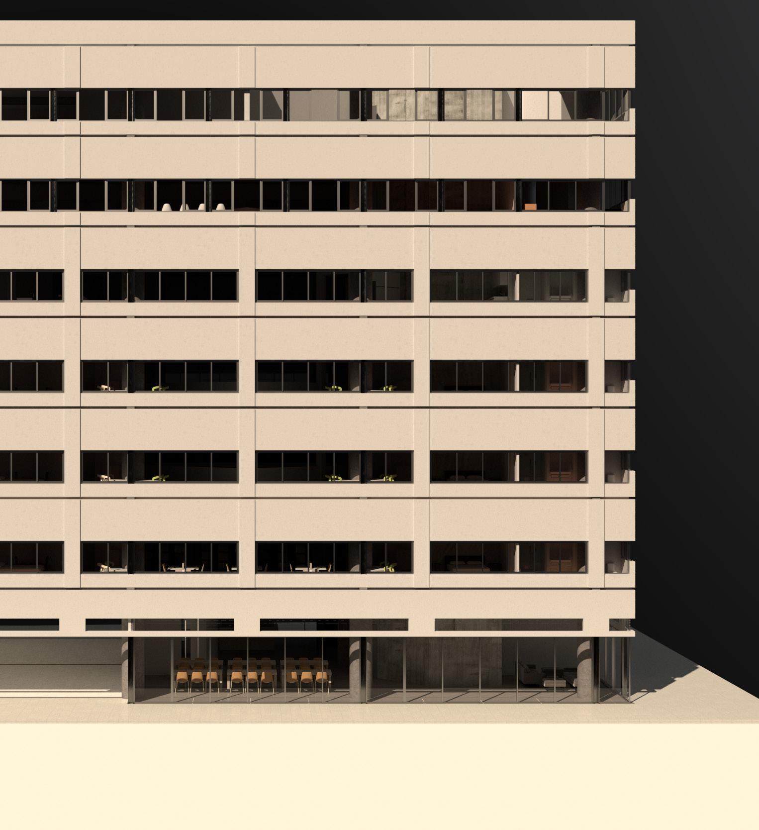


Due to the steering of the orthogonal system, the columns and beams intertwined with the void, so that the overall space is coherent in feeling, completely detached from the configuration of a corridor and a room.
The common areas each form small corners, so that maximum independence can also be obtained in a completely open space. In addition to sleeping, washing and napping, the main activities: dining room, living room, and kitchen are arranged in the common area. The space is configured more precisely. With a new configuration and spatial form, co-living is more complete and executable.
Orthogonal Orthogonal Co-living House
Look around from the base: intricate hostels stand on the hillside in the north of the river whereas subdued tea plantation and rural houses lie in the south. The strong contrast between north and south is suddenly possible to be described and linked again by the constructure design of therme and hanging bridge. Responding to the cycle of water, the design also connects the environment, and finally reaches the body.
The cantilever roof supported by the beam that traverses the hot springs and the weight of the mountain slope. Along the beam, the changing rooms lead to the edge of the concave ground are in the opposite directions. The therme and the heat converge correspond to the gradient of the ground that varies the temperatures. The bodies explore the sensory of experience that along the changes in the slope. Immersing in the deepest contradiction that between the two entrances merges as they converge with the therme. The beams and the slope create a precise height, that choose to intersect of the two sides.
The bridge deck begets tension and open up a gap, by a roof a side and two horizontally narrowing walls. The body follows the bridge, slowly descending from above the roof into the bridge. The senses follow the bridge, transitioning from the top of body to bottom, from the sky to the river valley.
Despite the inability to visually connect with each other due to the terrain, the therme and the bridge transform the relationship between structure and environment back into the realm of the body. In doing so, the therme and the bridge depict Dongpu, portraying the interplay between humans and nature. Through architecture, these elements are edited into a fragment that can be read and intimately connected with the surrounding environment.
Therme and Bridge ,Dong Pu,Taiwan 2023 Therme and Bridge


Hot springs that bring in sightseeing, mist in the mountains, and walls of houses mottled by rainwater... There is a certain contradiction of Dong Pu, which is extremely divided, but there are some things that are extremely close.
The relationship between people and the environment have the opportunity to be described in architecture.
I wanted to use two types of architecture: a bridge to cross and a hot spring to stay, one at the entrance to the village, and the other at the turn of the stream. At the same time, it is a guide to movement, suggesting a new way of experiencing. The public therme will also provide a place where the aborigines who have lived in Dong Pu for a long time, can soak in hot springs.
Therme and Bridge fig.2溫泉區 fig.3保護區 fig.2The beams that suspended over the hot springs, which make the structure stand and also divide the hot springs into two experiences. Follow the beams, enter from both sides, through two changing rooms in opposite directions, to the edge of the pool.
The curved shape of the floor allows the hot spring and the heat to cohesive, and the same heat corresponds to the gradual change of the floor, and the body begins to explore the heat and fog that changes due to the slope.
The hint of the two entrances converges along the slope of the hot springs, and at the deepest spot, the beams, which were originally 50 cm above the ground (water surface), finally open up to a comfortable height with the depth, where the two options converge. The deep beams cantilevered the folded roof against the weight of the hillside. The columns and diagonal braces at the lower end of the beam transfer the force back to the raft base that carries the therme.
The roof and the hot spring form a mutual relationship. Continue along the pavement, the depth slowly becomes shallow, back to the washroom on the same side, the shower room is opposite to the exit of the changing room at the beginning, from the extreme outside to the inside, compressed to open, extremely cold and extremely hot, outside and inside the mountain.


Kerbstones~150t
bottom End joint intergrate with drain.
First time Grouting
Pre-froced Rebar
Second time Grouting
The other Side Joint
Pebbles of different sizes affect the tactile sensation of the feet, with small pebbles suggesting movement and large pebbles staying. Following the elevation, can choose the depth of immersion.
The fluctuating water surface is reflected on the folded roof, and the creases are staggered along the embedded steel bars to form a preliminary.


Horizontal
Therme and Bridge A sideways column supports a short wall and roof. The cantilevered wall and roof are hoisted from each other, and ended at the two sides foundation. Tension of the wall causes the hoisted tread to hang down steadily. walls and vertical columns intertwine the sensory transformation with the entire bridge structure. Therme and Bridge

 1 Therme and Bridge
Left : Rain , 1958, Agnes Martin


Due to the topography, the therme and the bridge, which cannot be seen from each other, are overlapping. It deviates from all the main areas of activity, but indirectly describes Dong Pu, people and nature. Through architecture, the whole area can be sense more precisely
Ornament/Tectonic : Dynamic casting by Phase Transition
Acadamic Work non site
Tutor : Wei-Siang, Tseng
3D Printing Formwork
Acadamic Work non site
Tutor : Yu-Ting, Sheng (ROSO COOP)

experement 2-2
experement 3-1
[ experement 2-2 / type 5 ]
ORNAMENT ANALYSIS ]
Dynamicity of Concrete Casting ,doing experement at my house,Taiwan Left
experement proto
experement 1-1
"Dynamic Casting" will challenge the traditional concept of "concrete shape = formwork shape", and try to make the form of concrete establish without a preset structure. In this design, we will set up an experimental method to discuss what "dynamic watering" means, and develop a usable architectural space based on the experimental results.
工法的熟悉、量產需求降低、獨特性的追求
來自材料本身特性的閱讀、展現
工法從材料重新思考、完整性構築
800g/layer | s:1.5cm³
800g/layer | 500g(base)
Ornament/Tectonic : Dynamic casting by Phase Transition
[ Cast Setting ]
[ experement 1-2 / type 2 ]
[ CASTING _ FIRST STAGE ]
experement 1-1
[ Casting Experience ]
[ Casting Overlay ]
experement 1-1
experement 1-2
experement 1-3

experement 2-1


experement 2-2

experement 1-2


experement 3-1


experement 1-3

experement 2-1

experement 2-2
experement 3-1

[ experement 2-2 / type 5


 type1 type2
type3 type4
Left : from top
Stage1 Casting Steps
Stage1 Casting Experements
Right : from top
Type5 Casting Process
Types due to different variables
I try to discuss the decoration of the material as a form in the search for the essence of concrete casting. Through the adjustment of the basic elements of cement, water and mold, the watering can find a balance between predictable and unpredictable periods. The final form is naturally generated in the process, and the overall construction method and manufacturability are found.
[ experement 1-2 / type 2 ]
In this experiment, the watercement ratio was used as a variable. Part of the water was converted into ice, serving as support for the cement while also creating a "void." Throughout the process, the cement remained fluid until it ultimately solidified.
After forming, the lower end of the floating model clearly showed wave-like or angular forms, representing the most direct interface between the two materials. This presented the final state of the process.
In the later stages of the experiment, dry powder was poured over the ice blocks.
[
experement 1-2 / type 2 ]
[ Casting Overlay ]
[ Casting Overlay ]
[ experement
Observing the surface of ice and cement in the middle of the interface, I began to ponder how I used to understand the concrete surface in this concrete jungle, which was covered with other materials.
Looking at history, the Second Industrial Revolution truncated a lot of over-decoration before the 20th century. Adolf Loos wrote about the Ornament et Crime…….
But few people know that the first discovery and use of reinforced concrete was not in the orthogonal system of columns and beams, but by a horticulturist who was testing variable pots and containers.
In addition, looking back at the earlier period, prehistory, the Roman period, the application of cement was actually the casting of geometric repetitions of the past, and the empirical transformation of the Greek or earlier use of stone. Therefore, the early concrete buildings all showed a certain carving.
Viewed in a longitudinal way, in fact, at different stages and at different points in time, some similar contexts can be read. The geometric repetition of Greco-Roman watering comes from the cognitive learning of stone, which is re-watered from a carving angle.
Loos is a constant critic of ornamentation, but the interiors in his work are filled with a variety of colors, most of which come from the materials themselves. Crobusier reused cement in his profession, as if discovering something, and later on the surface became less and less colored, and the material returned to its original form.
The decoration of decorating comes entirely from the presentation of construction methods and materials.
Facing Page : Casting History and Ornament
100g / s:2.5cm³ 0+250g | 0
CEMENT HISTROY AND ORNAMENT ANALYSIS ]
world war one start World War two ends
裝飾被指像炫富、量產需求增加
standardized, module, mass-produced/super structure
工法的熟悉、量產需求降低、獨特性的追求
工法從材料重新思考、完整性構築
different method based on past 來自材料本身特性的閱讀、展現
[
experement 2-2 / type 5 ] [ Casting Experience
2-2 / type 5 ]
By my understanding of the historical use of cement, at the beginning of stage two of the experiment, I provided a setting for the potential generation of space. I chose a powder with low fluidity but which would actively hydrate with ice blocks, continuing the support and voids provided by the ice blocks in stage one.
The cement powder was layered with ice blocks in an attempt to find an appropriate relationship pattern between the ice and powder in spatial formation.
This appropriate pattern responds to both construction methods and spatial generation in terms of form.
The mold was no longer the main focus of the experimental setup but rather provided a framework within which to work.
experement 2-3
experement 2-3

experement 1-1
experement 1-1
[ Casting as Tectonic ]
[ Casting as Tectonic ]

experement 1-2
experement 3-1
experement 3-1

experement 2-1

experement 2-2
3-2
experement 4

experement 2-3
[ Experement 3-1 ]
[ Experement 3-1 ]

experement 3-1

experement 3-2
800g/layer | s:1.5cm³
800g/layer | s:1.5cm³
800g/layer | 500g(base)
800g/layer | 500g(base)

[ Dynamic in Casting ]
experement 1-1
experement 2-1
experement 1-2


 Ornament/Tectonic : Dynamic casting by Phase Transition
Above :
Ice Shape Testing(Before Stage2)
Below :
Stage2 Casting Models
In the preliminary stages of the experiment, different forms of ice blocks were tested. It was found that crushed ice was the most accessible, easy to transport, and moldable, with a larger contact area with the powder, resulting in more successful irrigation.

4000g/layer | s:1.5cm³
1500g/base | 4500g(base)
4000g / 6000g | 0.66 /
800g/layer | s:1.5cm³
800g/layer | 500g(base)
3200g / 3700g | 0.86 /
After achieving the self-forming space, the experiment advanced to more challenging tasks involving stacking heights and the degree of lateral cantilever.
Simultaneously, it was observed that a special texture forms on the contact surface with the ice blocks. The bottom of the model is composed of irregular fragments that fell during the process, serving as a record of the self-contained process.
These discoveries seem to bring me closer to the answer I am seeking: What is "dynamic casting"?
Ornament/Tectonic : Dynamic casting by Phase Transition
This construction method revolves around the fundamental element of irrigation: water, transformed into ice, combined with cement powder. I only control the approximate position, size, and quantity of the ice blocks, as well as the amount of cement powder, while the rest is generated by the materials themselves.
As the relationship between ice and ambient temperature dictates, the irrigation process begins. The ice gradually melts, the cement hydrates, and the space gradually takes on a natural form.
The organic structure, form, and finish, unlike traditional cast decorative elements, are not predetermined but entirely derived from the process of construction: materials, environment, gravity. The final outcome is a spatial configuration never before seen, offering sensory and speculative experiences that are also dynamic.


The challenge is to explore the limits and achievable forms of the 3D printing template compared to traditional construction methods, within the constraints of wooden templates and column-beam structures.
Using the KUKA90 six-axis robot, which can freely move within a defined range and achieve precise positioning through positioning and file programming.
PETG material is used for its properties of heat softening, cooling solidification, and recyclability after heating, allowing for repeated use.


一模板角色生長出可扣合的wing,防止漿體液出,也發現若要長出前面設計的列印 方式和wing生長方向相牴觸。


思考進入到真實尺度灌注的壓力,我們設定了兩種灌注姿勢:躺、站做測試。因 wing直接以垂直角度生長,影響脫模較困難。
two kinds of grouting position continuous unit
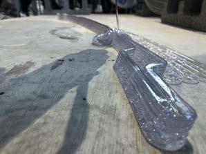
In printing, we first observe the possible variations of molds with irregular shapes from a small printer, and then correct them. Hands-on robot printing, through the change of curvature to test the limit of the printing material stacking, and the shrinkage error of the printing. Use both parameters to generate a mold.


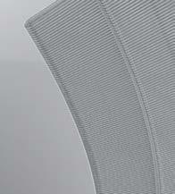
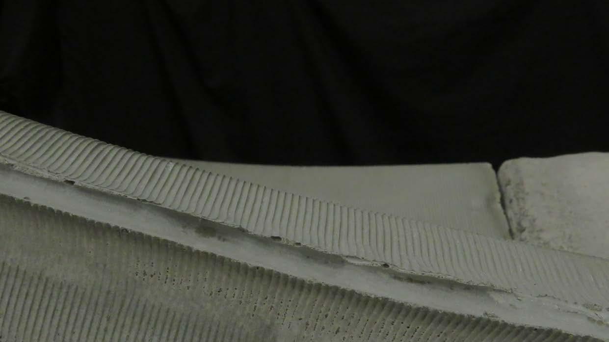
Based on the former, we test the possible curvature changes with the mobius shape. In the process of generating the formwork from the form, the conditions required for the pre-test variables and the casting situation are inserted, so five details are added: Wing/Brim/Offset/Truss/Chamfer. Wing: The position of the fixture during watering, Brim: fixed to the printing platform to prevent shrinkage errors, Offset: to increase the strength of the formwork, Truss: to make the curved formwork stand on the ground, and Chamfer to increase the expansion joint required for the crown. Due to the time constraints of the semester, we tested U1~4, four units with different curvatures for printing and watering.


 brim
wing
chamfer




about 10 degree with ground

20

Due to the circular type, each unit will have different angles and gradients during printing. Adjust the speed of the head movement in response to the high level of the gradient, decelerate at the position where the height is relatively high, and accelerate the opposite level, so that the dwell time of the extrusion vehicle is different, and it can be stacked evenly. As for the inclination angle, adjust the vertical printing of the tip so that the extrusion method is not affected, and also test the adhesion state of materials with different inclination angles.
about 36 degree with ground


Left
Details Setting for Formwork
Wings for later assembly
Brims fixed to plane to prevent warping
Truss for grouting position and pressure offset for printing
chamfer for better demoulding





 FORMWORK1
SCREW
SPACER
MESH
PIPE
FORMWORK2
fixture used
timber snap with PETG formwork
There are two position of casting tests, lying and standing, respectively, with different openings for pouring and closure.



Appendix 2018
Shadow and Light 2019
Gradient Test Tube
House of an Architect
2020
Facade Renovation
Miaoli Wenchang Temple Pysical Model
/ Onsite
Curriculum Vitae

 Shadow and Light


A series of gradient models, in which the spatial structure is graded from the openings of the volume and subtraction into continuous folded plates and large surface openings. The height difference of each floor is adjusted in a fixed unit to form a coherent interconnected space. At the beginning of the design, a set of ten models was produced as a reference for the subsequent architectural space.


 Sculpture Museum_ Gradient Test Tube stage2
Previous-stage models, translation, picking, scaling, rotation, and so on. A sculpture gallery and a guest house on the other side.


 Sculpture Museum_ Gradient Test Tube stage2


 House of an architect and family
The design coexists an architectural office and a residential building on a single site, discussing the relationship between public and private. The two buildings are separated from the outside of the site, and through the opening of the ground floor of the office, a public entrance is created on this side, and the residence and the office are separated by green space and direct separation, and the overall space is consistent and connected through the relative window sight and space function on both sides.


 House of an architect and family


This design project involves a facade renovation for an existing old building on the site. Only the facade will be altered, with no changes to the interior or structure.
Firstly, at the ground and second-floor arcade areas, two-story-high arcades are designed to highlight entry into a space that is ambiguous but distinct from the surrounding street houses. This design also utilizes the constraint of retaining all columns and beams to express a relationship between old and new.
At the corner, a four-story-high arched opening is created as the main entrance to all spaces. Circular windows are designed around it to accentuate the imagery.
On the fifth floor, existing windows are retained but converted into inward-opening casement windows.
On either side of the curved facade, repetitive use of hollow metal bricks. The lines are fixed vertically, with bricks clipped onto the metal lines, mirroring the large-scale facade advertisements in the surrounding urban landscape. The positioning of the hollow bricks can be adjusted arbitrarily, either arranged to form certain patterns or placed randomly.


 Facade Renovation


 Miaoli Wenchang Temple(literary flourishing)
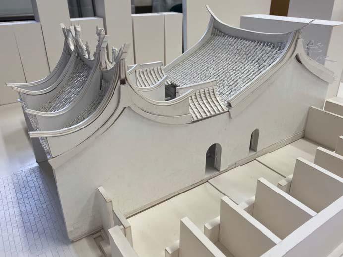
In the history of Chinese architecture, we study the Miaoli Wenchang Temple, and use models to understand the structure and details of traditional Chinese architecture. In addition to the main building, the original gables, cherished word pavilions, incense burners and other originals are all words that often appear in Chinese temple architecture.




2022 spring
Danamic Casting Project Charrette

2023 summer
Diploma Project Charrette at FCU with
Tutor : Cheng-Syuan, Wu (Host of AAA)
Review Jury : Bo-Sheng, Liu
Bo-Ren, Zheng
Yuan-Sung, Siao
You-Han, Lin (Host of Behet Bondzio Lin Architekten)
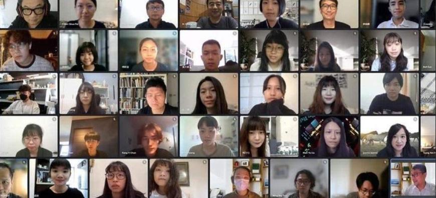
2021 summer
Asian Architectural Young Talent Award (The First Prize) with
Tutor : Wen Ying Huang
Review Jury : Ih-Cheng Lai
David Hong
Cheng-Hsuan Chen
Wan-Yu Liu
Cheng-Luen Hsueh
Chien-Shao Bai
Ming-Wei Huang
Youngil Lee (the Host of the award)

2023 summer
Diploma Project Charrette at Song Shan Cultraral Park with Review Jury : Wei, Tseng (Professor at Tungh Hui University)
Ling-Li, Tseng (Host of Serendipity Studio)
Wun-Jie, Ciou (Host of Wun-Jie, Ciou Architecture Sudio and AxB Architecture Studio)
Jia-Ru, Lin (OMA's Representative of Taiwan)
2020 summer Construction site VisitCurriculum Vitae
傅軒慧
Hsuan Hui, Fu

Eduction
2018-2023
Experience
2018/07-09
2021/07-09
2022/07-09
2023/09-present
逢甲大學 建築專業學院學士班 Feng Chia University
The Department of Architecture (Bachelor)
大渡城鄉建築師事務所 (Dadu Urban and Rural Architects Office) 元築工場設計公司
(Yuanzhu Factory Design Company)
技聯組工程顧問股份有限公司 (United Technical Group Engineering Consultants Ltd.) 群甡建築師事務所 (Qun Zong Architects Office)
Software Abilities
Rhino
Vray
Photoshop
Illustrator
Indesign AutoCAD
ArchiCAD
Award
Asian Architectural Young Talent Award (The First Prize) Taiwan 20
Team 20
Diploma Project of Feng Chia University, The Department of Architecture (The Second Prize)
