Salice Evolift
Lift system for flap doors
FR Flap Door System
• Available in soft close or push to open versions
• 2 strengths available to suit most applications
• Adjustable spring tension


• White covers (order separately)
• Suits doors 300mm - 600mm high


• Suitable for double or single system applications
• Door weight can be calculated for 18mm thick MDF door by: Height of door (in meters) x Width of door (in meters) x 14

1 set contains:
• 1 Mechanism (left or right hand)
• 1 Mounting plate
• Assembly instructions and template
Soft Close Mechanisms
Part No. Side Strength
SAL.FRMFXXXDSN9D Right hand Weak
SAL.FRMFXXXDSN9S Left hand Weak
SAL.FRMFXXXFSN9D Right hand Strong
SAL.FRMFXXXFSN9S Left hand Strong
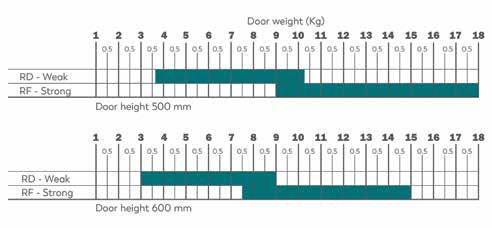
Charts to select the exact system suitable for the dimensions and weight of the door. It is suggested that some assembly trials are made.

Doors using a single stay (either right hand or left hand)
Push to open mechanisms
Catch & retaining catch recommended - see page 96
Part No. Hand Strength
SAL.FRMFXXPDSN9D Right hand Weak
SAL.FRMFXXPDSN9S Left hand Weak
Covers
Right Hand Cover - White
Left Hand Cover - White
Doors using 2 stays
55
Description
Part No.
SAL.SRDM78AQSNXXF
SAL.SRSM78AQSNXXF
The normal door weight calculation we use is:
Salice Evolift - Flap Doors
Installation Instructions
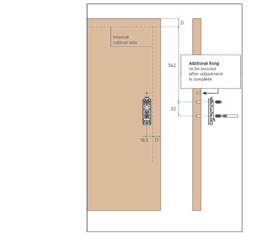
Drilling pattern for wooden door
Hinges for doors with soft-close and handles: SAL.C2P6A99
Hinges for doors with Push opening: C2R4A99 (unsprung hinges) for a softer opening
D=Cabinet door overlay

56
Salice Evolift - Flap Doors

Installation Instructions
Drilling depth 12 mm - Hole diameter ø 5 mm

57
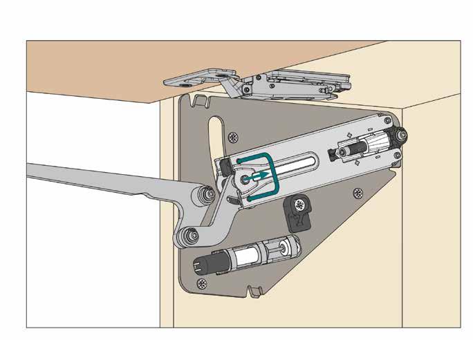
Fixing the system to the cabinet side.
Fitting the door to the cabinet.
Salice Evolift - Flap Doors
Withdraw the safety clip. Lower the door slightly until the safety clip can be easily withdrawn.

Adjustment of the system strength. Use a Torx bit T20.

58
Installation Instructions
Salice Evolift - Flap Doors

Adjustment of the decelerating effect.

59
Adjustment of the opening angle of the door, by cam, from 80° to 92°.
Installation Instructions
Salice Evolift - Flap Doors


60
Installing the cover.
View of the mounted system.
Installation Instructions
Salice Evolift - Flap Doors

61
of the door. Installation Instructions
Removal
Salice EvoLift
For folding doors


62 FP Parallel door system
Salice Evolift
Lift system for folding doors
FL Folding Door System
• Soft Close
• 2 strengths available to suit most applications
• Adjustable spring tension


• White covers (order separately)
• Suits doors 570 - 940mm high (height of both doors)


• Possible to use one mechanism for smaller doors
• Door weight can be calculated for 18mm thick MDF door by: Height of door (in meters) x Width of door (in meters) x 14
1 set contains:
• 1 Mechanism (left or right hand)
• 1 Mounting Plate
• 2 Central hinges
• Assembly instructions and template
Covers
Charts to select the exact system suitable for the dimensions and weight of the door.

The indicated weight capacities refer to a pair of arms.
For doors of small weight and dimensions, it is possible to use one system only, right or left version. It is suggested that some assembly trials are made.
Right
63
Part No. Description SAL.SBDM78AQSNXXF Right Hand Cover - White SAL.SBSM78AQSNXXF Left Hand Cover - White
Part No. Door Height Strength SAL.FLMF60XDSN9SP 600mm Weak SAL.FLMF60XFSN9SP 600mm Strong SAL.FLMF66XDSN9SP 660mm Weak SAL.FLMF66XFSN9SP 660mm Strong SAL.FLMF72XDSN9SP 720mm Weak SAL.FLMF72XFSN9SP 720mm Strong SAL.FLMF78XDSN9SP 780mm Weak SAL.FLMF78XFSN9SP 780mm Strong SAL.FLMF91XDSN9SP 910mm Weak SAL.FLMF91XFSN9SP 910mm Strong
Left Hand Mechanisms Part No. Door Height Strength SAL.FLMF60XDSN9DP 600mm Weak SAL.FLMF60XFSN9DP 600mm Strong SAL.FLMF66XDSN9DP 660mm Weak SAL.FLMF66XFSN9DP 660mm Strong SAL.FLMF72XDSN9DP 720mm Weak SAL.FLMF72XFSN9DP 720mm Strong SAL.FLMF78XDSN9DP 780mm Weak SAL.FLMF78XFSN9DP 780mm Strong SAL.FLMF91XDSN9DP 910mm Weak SAL.FLMF91XFSN9DP 910mm Strong
Hand Mechanisms
Salice Evolift - Folding Doors
Drilling pattern for the upper wooden door.

64
Installation Instructions
Salice Evolift - Folding Doors
Drilling pattern for the lower wooden door.

D = sideways overlay
To determine the B value, use the table on page 66
1 - sideways adjustment ± 1.5mm
2 - height adjustment ± 1.5mm
65
Installation Instructions
Salice Evolift - Folding Doors

66 Arm Length LHT Cabinet Height Formula to determine the B value 600 570 - 630 475 + D - HT - A 660 631 - 690 505 + D - HT - A 720 691 - 750 535 + D - HT - A 780 751 - 810 565 + D - HT - A 910 881 - 940 634 + D - HT - A
Installation Instructions
Salice Evolift - Folding Doors

Installation Instructions

67
Fixing the system to the cabinet side.
Fitting the door to the cabinet.
Salice Evolift - Folding Doors
Withdraw the safety clip. Lower the door slightly until the safety clip can be easily withdrawn.
Adjustment of the system strength. Use a Torx bit T20.


68
Installation Instructions
Salice Evolift - Folding Doors
Installation Instructions


69
Adjustment of the decelerating effect.
Installing the cover.
Salice Evolift - Folding Doors


70
Installation Instructions
View of the mounted system.
Removal of the door.
Salice Evolift - Folding Doors
Installation Instructions
Dimension of the arm In the closed position.
Dimensions of the system.
Dimensions correct at bracketed cabinet height*


71
* *
Salice EvoLift
For parallel doors


72
Salice Evolift
Lift system for parallel doors
FP Parallel Door System
• Soft Close
• 2 strengths available to suit most applications
• Adjustable spring tension
• White covers (order separately)
• Suits doors 360mm - 600mm high


• Stabiliser bar must be used (order separately)


• Door weight can be calculated for 18mm thick MDF door by: Height of door (in meters) x Width of door (in meters) x 14
1 set contains:
• 1 Right Hand Mechanism
• 1 Left Hand Mechanism
• 2 Mounting Plates
• Assembly instructions and template
Mechanisms Stabiliser Bar
SAL.FPMFCXXDSN9 360mm - 440mm Weak
SAL.FPMFCXXFSN9 360mm - 440mm Strong
SAL.FPMFLXXDSN9 440mm - 600mm Weak
SAL.FPMFLXXFSN9 440mm - 600mm Strong
Chart to select the exact system suitable for the dimensions and weight of the door.
It is suggested that some assembly trials are made.
73
Covers Part No. Door Height Strength
Part No. Door Height SAL.FPMF59Q1039 Stabiliser Bar Part No. Door Height SAL.SPXM78AQSNXXF Cover set - White 0.5 0.50 .5 0.50 .5 0.50 .5 0.5 0.5 Door w eight ( Kg) Door height from 360 m m to 6 00 m m PD
- W eak PF - S trong
Salice Evolift - Parallel Doors
Drilling pattern for wooden door. For doors from 360 mm to 440 mm height.
D= Sideways and upper overlay
Drilling pattern for wooden door. For doors from 440 mm to 600 mm height.

D= Sideways and upper overlay

74
Installation Instructions
Salice Evolift - Parallel Doors
Installation Instructions


75
Fitting the door to the cabinet.
Fixing the system to the cabinet side.
Salice Evolift - Parallel Doors
Installation Instructions
Withdraw the safety clip. Lower the door slightly until the safety clip can be easily withdrawn.


76
Fitting the stabiliser bar.
Salice Evolift - Parallel Doors
Installation Instructions
Adjustment of the system strength. Use a Torx bit T20.

Adjustment of the decelerating effect.

77
Salice Evolift - Parallel Doors
Adjustments of the door.

Additional

78
Installation Instructions
fixing to be secured after adjustment is complete.
Salice Evolift - Parallel Doors
Installation Instructions
After adjustments are complete, detach the stabiliser bar to install the cover. Then re-attach the stabiliser bar.


79
View of the mounted system.
Salice Evolift - Parallel Doors


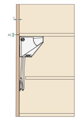
80 Kinematic motion of the system. Removal of the door 360 - 440mm SP X Max 16 29 18 31 19 31 20 32 22 33 360 - 440mm T AC Min 19 3 22 3.5 25 4 440 - 600mm SP X Max 16 25 18 27 19 28 20 28 22 29 440 - 600mm T AC Min 19 2 22 2.5 25 3 Installation Instructions
Salice Evolift - Parallel Doors
Installation Instructions
Dimensions of the system for doors from 360 mm to 440 mm height.
*Dimensions correct at 360mm cabinet height

Dimensions of the system for doors from 440 mm to 600 mm height.
*Dimensions correct at 600mm cabinet height

81
* *


