11 minute read
Emerging Renewal Technologies for Pressurized Pipelines—Steve Soldati
FWRJ Emerging Renewal Technologies for Pressurized Pipelines
Steve Soldati
Advertisement
Pipelines that carry flows under pressure represent a special set of challenges for water and sewer rehabilitation. Historically, most pressurized pipelines were rehabilitated using open cut construction. Part of the reason for that choice has been a lack of trenchless rehabilitation technologies appropriate for pressurized pipelines. A lack of investment in aging pressure pipe infrastructure, coupled with increasing congestion (both above and below ground) has accelerated development in the trenchless rehabilitation industry.
This article reviews the concept of structural classification for pressure pipe linings as defined by the American Water Works Association (AWWA), and where emerging trenchless renewal technologies fit within the AWWA classification framework.
Five case studies are presented that utilized separate trenchless products for pressure pipe rehabilitation: S Carbon or glass fiber-reinforced polymer (FRP) S Cured-in-place pipe (CIPP) S Tight-fit high-density polyethylene (HDPE) pipe S Fusible polyvinyl chloride (Fusible PVC®) pipe S Hose lining system
Discussed is the engineering, material construction, installation, and cost-effectiveness of each product with the intent to demonstrate the strengths and limitations of each.
The State of Aging Infrastructure
The AWWA recently published its “2020 State of the Water Industry” survey, which identifies critical topics and tracks trends to help raise awareness within the water industry. This survey covers all aspects of the industry, including infrastructure assets, water quality, water resources, and agency staffing. The one thing that stands out the most from the report is that, for the fifth consecutive year, renewal and replacement of aging water and wastewater infrastructure, and financing for capital improvements, have ranked as the top one and two issues, respectively, facing the industry.
Figure 1. Selection of rehabilitation techniques to resolve water quality problems. Steve Soldati, P.E., is regional sales manager of pressure pipe–east region with Aegion Corp. in Tampa.
The Cost of Doing Nothing
Asset management 101 says that the longer the wait to address an aging asset, the more expensive it will be to replace, renew, or rehabilitate it. Take roadway pavement for example. Over time, as cars and trucks ride over the pavement, it slowly degrades and develops tiny vertical cracks at the surface. As the vehicle flows continue, those tiny cracks begin to propagate deeper into the pavement thickness. In the early years of these cracks, they are shallower, and it takes only a minimal thickness to remove and repave with new asphalt to restore the roadway free of cracks. If that same roadway, however, wasn’t repaved until several years later, those cracks would be much deeper (if not full depth), much more asphalt would need to be replaced, and therefore, it would increase the cost substantially. This causes a higher replacement cost, but is also much more disruptive to the traveling public and the local community.
Traditional Methods of Replacement and Its Hardships
The traditional method of addressing pressurized pipelines has been to dig and replace. This is a conservative method to restore structural integrity, improve water quality, protect pipes from further corrosion, and reduce maintenance costs. This method, in some instances, can be the best path forward, given that the pipeline is in an open space with easy access, little or no other utility conflicts exists, and/or the pipe depth is relatively shallow.
The problem with many pipelines needing to be replaced today is that it isn’t always a preferred site condition that makes dig and replace a clear winner. There has been continued development built on top of existing pipelines, additional other utility infrastructures put Continued on page 46
Figure 2. Selection of rehabilitation techniques to resolve water flow, pressure, and leakage problems. Continued from page 44 in the ground, and easement and access agreements that have changed. These scenarios add a layer of complexity and consideration to rehabilitate the pipeline in question.
Another critical aspect is the need for urgent and emergency response for failing infrastructure. Often times, an engineering firm is heavily involved, and the process to move from condition assessment, to design, and then to construction bid is lengthy and is not set up as well for urgent or emergency projects. The AWWA Manual M28, Rehabilitation of Water Mains, provides guidance on identifying the key elements for rehabilitating a pipeline. It provides both owners and engineers the tools to move from concept, to design, and ultimately, to rehabilitation work in the field.


There is Hope
`The challenge with the renewal and replacement of infrastructure is that society relies on this infrastructure every day. The unfortunate reality is that there is a cost to doing nothing, as stated previously, in fear of too much disruption to daily life, and there is a cost to having to shut down operations for an extended amount of time to address the aging infrastructure that is at risk of failing at some unknown point in the future. This can be a “Catch 22” scenario, with either direction that’s chosen becoming too burdensome.
Technological advancements over the past several years have provided additional construction options that can improve the operational downtime, reduce total project costs, and achieve the project goals. The old construction adage is, “Among quality, budget, and schedule, you can pick two.” This simply means that if you want a project to be high quality and fast, it’ll be expensive; for it to be high quality and cheap, it will take a long time; and for it to be inexpensive and fast, it will be poor quality.
These are the factors of any project that owners and engineers usually weigh for making the decision to move forward with a particular solution.
The challenges that various utility agencies and municipalities face, with reduced project costs and reduced schedules—while providing a high-quality result—are the same goals shared by private and other industry sectors. The question is how infrastructure, or assets, can be replaced or renewed, while minimizing downtime in the most cost-effective way.
Choosing the Right Solution
rehabilitation path is critical. Understanding the existing pipe condition and design will set the proper foundation for moving forward with the appropriate trenchless method. The AWWA M28 has assisted in this assessment and the selection process of the right rehabilitation technique using the decision trees, as shown in Figures 1, 2, and 3. Although M28 is geared toward water mains, many of the same principles can be applied to other pressurized pipelines. Many of the aging pressure pipes are in need of a structural solution, so Figure 3 will be the most common guidance for selecting the right rehabilitation method.
There are several trenchless technologies available for various pipeline applications, with each technology having its preferred application, given the site parameters, design, and existing pipe layout.
Cured-in-Place Pipe
The CIPP is engineered and manufactured to project specifications and can be designed as an interactive or independent solution to meet pipe rehabilitation goals. This pipe-within-apipe, as shown in Figure 4, has the ability to rehabilitate any pipeline to a fully structural M28 Class IV solution, such that the existing host pipe can deteriorate away and the owner is left with a brand new pipeline. The CIPP can be installed up to several hundreds of ft at one time and does not hinder the flow capacities of the pipelines. With only two small excavation pits on either end of the installation, the rest of the facility operations above the pipeline will not be disrupted during the rehabilitation process.
The City of West Palm Beach had embarked on one of the largest projects of its kind to rehabilitate a more than 40-year-old prestressed concrete cylinder pipe (PCCP) force main running directly through a golf course, densely populated neighborhoods, and stormwater ponds. A condition assessment concluded that the number of pipes segments with broken wire wraps provided a significant risk of failure.
Traditionally, an open cut or sliplining operation would be the chosen path forward; however, both traditional options were rejected due to the cost and disruption of the open cut replacement and the drastic loss of the slipline. With these project parameters, the best solution was the close-fit CIPP, which provided minimal disruption to the residential neighborhood and golf course, while providing a fully structural M28 Class IV solution that maintained pressure rating and flow capacity.
Hose Lining
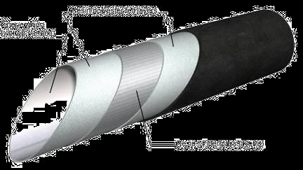
The advancement of hose lining systems has made it possible to address leaking or failing joints of pipelines using a slipline installation, which consists of pulling a new smaller pipe within the larger existing pipe, resulting in smaller work zones and smaller equipment for those harder-to-access pipelines. Hose liners are a simple three-part construction consisting of an inner and outer layer, with an internal reinforcing layer that provides the liner its full pressure capacity, as shown in Figure 5.
The hose lining systems are intended to be the M28 Class III solution, such that the new hose will withstand the internal pressures, but rely on the continued support of the existing host pipe from the external forces, such as soil, groundwater, and live loading. Hose lining materials require no resin curing (as with CIPP) and no long pipe laydown areas, similar to PVC or HDPE material, and are fused together to then be pulled into the pipeline during one active slipline pull.
The benefits of using the hose lining system are that it can be installed much quicker than CIPP due to the installation time and the fact that there’s no curing involved. In addition, the equipment is much smaller, so a smaller footprint is required for installation.
The Elizabeth River Tunnel in Virginia had a Continued on page 48

Figure 4. Cured-in-place pipe structure. Figure 5. Hose lining.


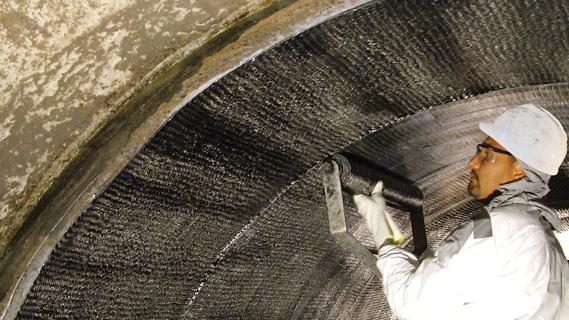
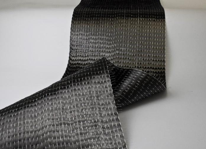
Figure 8. Fiber reinforcement. Figure 9. Fiber-reinforced polymer application inside a pipeline.

Continued from page 47 unique challenge that involved several thousand ft of fire and storm drain piping that was embedded in the tunnel concrete and had limited access to the pipeline itself. This made it difficult to mobilize the necessary equipment for most rehabilitation options. Since the piping was embedded in concrete, the external structure of the existing pipe was irrelevant and the internal rehabilitation was the primary focus to accommodate the internal pressures. The Class III solution allowed for the required installation equipment to be mobilized adjacent to the pipe location.
Tight-Fit High-Density Polyethylene Pipe Lining
Treddyfin Township, Pa., needed to rehabilitate 18,000 ft of 30-in. PCCP force main that had experienced major failures in its Valley Force National Historic Park. This pipe was more than 40 years old and had experienced three separate failures that expedited the need to address this pipeline with a structural solution. After review of different options, including open cut replacement, it was determined that a tight-fit HDPE rehabilitation was the best solution to meet the structural and flow capacity requirements. Since this pipeline was located in a difficult area, which included an historic site, heavily wooded land, and river crossings, the ability for this rehabilitation technique to achieve long installation lengths, while minimizing the disruption to the area, deemed it most beneficial.
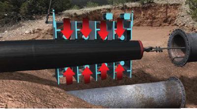
As shown in Figure 6, the HDPE pipe diameter is temporarily reduced through the Poisson effect, as the HDPE pipe is actively pulled through the host pipe. The use of a powered roller box at the insertion end assists with this procedure to reduce the overall stresses on the HDPE pipe during the active slipline procedure.
A total of 31 installations sections were installed using DR 26 and DR 32.5 HDPE pipe, with the longest section topping 1,500 ft. The DR is the ratio of the pipe outer diameter to the pipe minimum wall thickness. The lining system was designed to be slightly larger than the host pipe at 30.05 in. internal diameter.
This was a critical wastewater pipeline that needed to keep its flow capacity. The tight-fit HDPE solution was selected because it maintained maximum flow and was able to maximize the installation length, resulting in minimal disruption to the historically sensitive land. The unique installation method protected the habitats of the environment along the river.
Fusible Polyvinyl Chloride Pipe Using Horizontal Directional Drilling
A vast majority of the rehabilitation options available throughout the industry incorporates the existing location and layout of the host pipe. The only trenchless option that does not involve using the existing pipe is installing new pipeline using horizontal directional drilling (HDD). Not only can HDD be used for address failing pipelines, but it can also be used for pipe system expansions, making it a versatile solution for many pipeline projects. Figure 7 shows the insertion of the carrier pipe.
The benefits of HDD—with Fusible PVC— become apparent when project constraints and other project goals limit the feasibility or costeffectiveness of other rehabilitation options.
This was the case for a project in Panama City Beach. The project involved the installation of 5,400 ft of 24-in. Fusible PVC by HDD. The installation needed to cross a large body of water and setting up a bypass was next to impossible, which is required with other rehabilitation methods. With the HDD installation technique, the new pipeline was installed, while keeping the existing pipe in operation. Once the installation was complete, a quick turnover to the new pipeline was accomplished.


