13 minute read
Sub-millimetre-resolution UAS Dam Surveys


Dam Fine Data: Sub-millimetreresolution UAS Dam Surveys
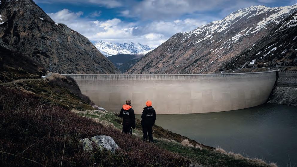
In early 2021, the Orthodrone team crowded itself and its equipment into a tiny Swiss gondola and made its way to one of two dams scheduled for water-side inspection – no easy feat, given the metres of snow closing off many alpine roads during the winter. Often situated in diffi cult-to-reach locations, Swiss pumped storage plants can greatly benefi t from sub-millimetre-resolution uncrewed aerial system (UAS) dam surveys. With the appropriate survey-grade, metric sensors, current UAS can offer safer access and increased cost-effectiveness compared with more traditional inspection methods, while providing comparable or better data.
MUCH MORE THAN CHOCOLATE, KNIVES AND CLOCKS: SWISS HYDROPOWER
Well over half of the energy produced in Switzerland comes from hydropower, and Axpo Holding AG is Switzerland’s largest hydropower producer. The canton of Graubünden, where this project took place, contributes over 20% of the electricity generated from hydropower in the country, totalling more than 7.9 billion kilowatt hours per year. Most of the hydropower in Switzerland comes from storage power plants and run-of-river plants, with only 4.3% of Swiss hydropower provided by pumped storage hydropower plants. However, pumped storage plants are an important component of a hydropower system, helping to balance supply and demand. In a pumped storage system, reservoir water is sent through pressure pipes to drive turbines that generate electricity to be fed into the power grid. In addition to providing energy during peak usage, pumped storage plants also allow for the conversion of excess electricity from the grid through the transfer of water from the lower reservoir to the higher reservoir during off-peak periods. This makes them a vital resource for smoothing energy consumption. Traditionally, water-side inspections of
the dams have caused signifi cant turbine downtime.
SWISS DAM SAFETY: AN INTERNATIONALLY RECOGNIZED REGULATORY SYSTEM
Throughout the lifetime of a dam, appropriate operation and consistent maintenance are essential for minimizing risk. Regular inspection helps to ensure the safety and continued operation of a dam, an area in which Switzerland – highly praised by the International Commission on Large Dams – has excelled, having had no dam failures since 1887. However, conventional dam inspections require resource-intensive data collection by means of workers atop platforms suspended from the dam, providing a prime use case for UAS dam surveys to improve inspection safety and effi ciency. Unlike popular consumer-grade drones, Orthodrone’s equipment includes madeto-measure UAS and metric cameras, made specifi cally for surveying and inspection. Phase One’s iXM100 is its favourite tool for photogrammetric data acquisition, allowing the Orthodrone team to get the sub-millimetre-resolution data required for a detailed analysis of the safety of a dam. Compared to cameras such as the DJI Zenmuse P1, the iXM100 not only has superior image quality, but also a faster trigger: within the typical two-second trigger interval for a single shot of the DJI P1, the iXM captures six images – requiring less fl ight time to capture the necessary data. With the current setup, the team can achieve a 1.5mm ground sampling distance (GSD), with a footprint larger than 17 x 13m, hovering at about 32m or 60m from the dam face (depending on the lens). A 1mm GSD (footprint roughly 12 x 9m) is possible at a distance of up to ~40m, whereas a 0.5mm GSD (footprint roughly 6 x 4.5m) can be attained up to ~20m from the dam wall.
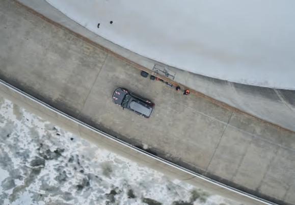
COMPLETE CONTROL FOR SHARPER IMAGES
While utilizing a cutting-edge industrial camera considerably enhances productivity, added automation eases the job. All of our
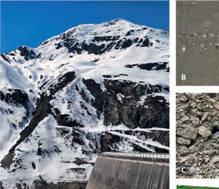
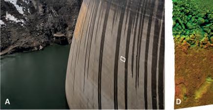
A: Survey site | B: Single image (cropped height) | C: Image at 100% zoom | D: Point cloud & analysis | GSD: 0.5mm/pix
UAS are equipped with real-time kinematic GNSS, Lidar-based rangefi nders and complete camera setting control, simplifying not only post-processing, but also allowing for sharper images with spot-on focus. This is particularly important due to the convex shape of most dams, which poses challenges for pilots and their spotters, especially during water-side dam surveys in gusty winds. Of the two dams we surveyed, one was 127m high with a crest length of 480m, and the other was 117m high with a crest length of 560m. Such areas also require terabytes of data storage for the desired sub-millimetre resolution of the images, making them a prime use case for our onboard processing units with signifi cantly larger data storage.
DELIVERABLES – IT’S ALL ABOUT PERSPECTIVE
With the gathered images and derived multidimensional deliverables, dam managers can assess the dam face for abnormalities or degradation. High-quality data is essential for a thorough assessment of structural integrity, and even the most miniscule cracks can be detected by sub-millimetre-resolution UAS dam surveying. This enables inspectors to identify areas of concern, which are then properly addressed to mitigate risks before they can turn into more costly and potentially more dangerous issues. Orthodrone is currently working on the development of a new, fully offshore capable, gas-hybrid multi-rotor UAS, which can combine two iXM100 cameras and a survey-grade Riegl Lidar while keeping the entire payload completely stable. Stability is paramount for fl ying in offshore conditions (or in this case, windy alpine valleys). High wind tolerance will make aborted missions due to high winds a thing of the past. The new system will also be able to carry a single, large focal length lens, enabling inspections at half-millimetre resolution from a distance of 40 metres, allowing for a new level of risk management while gathering the best possible data from afar.
ABOUT ORTHODRONE
Orthodrone is your reliable partner for drone-based critical infrastructure inspections – including sub-millimetre photogrammetric dam surveys in hard-to-reach areas. With hours of hover time and top-of-the-line sensors, Orthodrone is revolutionizing the way we gather, process and utilize spatial data. For a closer look at one of these dams, follow the link below to see the point cloud.
www.orthodrone.com/data
DYNAMIC FIELD OF VIEW HELPS TO MAINTAIN REGULAR SWATH
Lidar Survey in Cloudy Conditions in Cameroon
In Lidar surveys, minimizing fl ight time is the key to minimizing costs. Operators therefore carefully optimize parameters such as fl ight altitude, fi eld of view and pulse repetition frequency to cover the survey area at the desired point density with the fewest fl ight lines. One parameter that they cannot plan for, however, is the weather. This article outlines how a dynamic fi eld of view feature was used in a project in Cameroon to overcome the inability of Lidar laser beams to penetrate the persistent cloud cover.
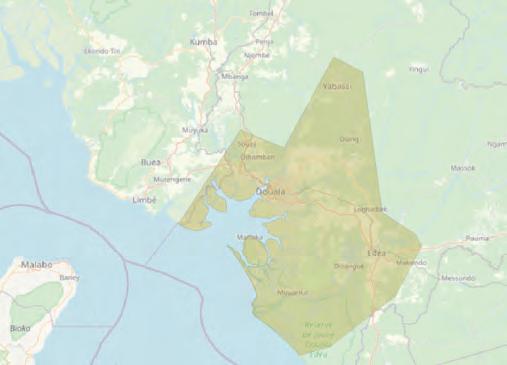
French survey company Société Topographie Informatique (STI) was contracted by the Communauté Urbaine de Douala (C.U.D.), a regional government body in Cameroon, to conduct Lidar and camera surveys for urban planning and fl oodplain management. Partially funded by Agence Française de Développement (AFD), the survey would cover a relatively wide expanse of 7,000km2 , including Cameroon’s largest city and economic capital, Douala, plus areas with natural land cover and large dense forests.
PREPARING FOR THE SURVEY
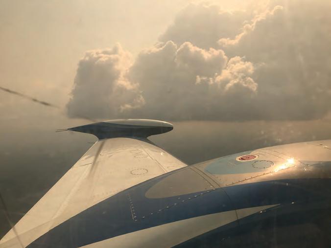
In the acquisition phase, close to 200 hours of survey fl ight time was planned over a period of two months in 2021. The STI team installed a Teledyne Optech Galaxy PRIME Lidar sensor and Phase One IXU-RS 1000 camera in a pressurized bi-turboprop Piper Cheyenne II XL aircraft and optimized the fl ight plans. While waiting for the right conditions to get the project underway, the team soon found out that the weather would be their greatest challenge. “The biggest problem we faced came in the form of low cloud cover that seemed to encompass the whole area,” said Bogdan Munceanu, STI project leader. Cameroon, located in the Gulf of Guinea in west-central Africa, is often described as ‘Africa in miniature’ because it has all the major climates and vegetation of the vast continent. Unfortunately for the team, Douala suffers heavy cloud cover for about nine months of the year. This is exacerbated by the humidity from the sea as well as haze, dust and perennial bush fi res, resulting in constant low cloud cover over the city and its surrounding areas. This poses a problem because one of the limitations of Lidar is that Figure 1: The survey area comprised 7,000km2 in and around Cameroon’s largest city, Douala.

the lasers cannot penetrate dense cloud cover and reach their target. Instead, the clouds ‘scramble’ the beam which prevents the target of interest (in this case the ground) from being mapped reliably.
WEATHERING THE CHALLENGES
Realizing the clouds were not going away, Munceanu was quick to accept that he had to fi nd a workaround for the problem. “With this survey we did not have the luxury to say that the skies are not looking so great this morning so let us fl y in the afternoon,” he said. “If we were lucky, we may have got half an hour of clear skies on rare occasions, but for the most part it was heavy clouds all day, every day. We could have waited for months and still not seen a whole day without dense cloud cover.” “Our plan was to fl y at an altitude of around 3,000ft (914m) above ground level (AGL),” Munceanu continued. “We recognized early on that the presence of the clouds would not allow us to stick to our fl ight plan. Once in the air, we would have to adjust the altitude depending on the altitude of the cloud. I fi gured if we stayed at the base of the cloud with varying adjustments of on average 300ft below the 3,000ft mark, we would be able to achieve the necessary results.”
For traditional sensors with fi xed fi eld of view (FOV), reducing the fl ight altitude in this way would have been a major challenge because the swath on the ground would get narrower, potentially creating gaps between fl ight lines that could be a basis for the client to reject the survey data. Instead, the operator would
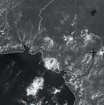
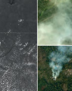
Figure 2: Meteosat HRV image of the cloud cover around the survey area (pixel size: 1km), with white speckles indicating large clouds that prevent a clear view of the land. Inset images show cloud cover over the area and the smoke caused by bush fi res
need to compensate for the narrow swath by packing the fl ight lines closer together – resulting in more fl ight lines, more survey time and more cost. STI, however, had a better option. “What helped us immensely was the Teledyne Optech PRIME’s SwathTRAK feature,” said Munceanu. “This allowed us to keep a regular swath on the ground even when we varied from our fl ight plan.”
DYNAMIC FIELD OF VIEW TO THE RESCUE
To keep the Lidar’s swath consistent, the feature constantly monitors the GNSS and IMU data to determine whether the aircraft is deviating from the fl ight plan. Such deviations can include both the aircraft’s position (too high, too low or too far to the side of the fl ight line) and its orientation (too much roll, pitch or crabbing). It also constantly monitors the range to the ground reported by the Lidar to determine whether the elevation of the ground itself is changing. By combining this position/orientation and ground elevation data, the feature can calculate whether these factors are distorting the swath on the ground and adjust the scanner’s FOV accordingly.
Teledyne Optech originally designed SwathTRAK for high-relief terrain, where it could increase the FOV when fl ying over hills and reduce the FOV when fl ying over valleys, thereby keeping the swath at a constant width and improving operational effi ciency and data consistency. Over the years, however, the feature has been further developed to handle many other conditions such as corridor mapping applications. In this case, STI realized that this solution could also compensate when the aircraft itself (not the ground) was changing elevation. Thus, when the aircraft had to fl y lower due to clouds, the FOV was widened to keep the width of the swath on the ground steady and avoid gaps between fl ight lines (see Figure 4). Notably, despite the reduction in altitude from 1,128m to 1,020m AGL, the operator was still able to get the full swath of 733m as the FOV expanded to achieve the planned coverage. Thanks to this fl exibility, the STI team did not have to replan based on ever-changing weather conditions since they were guaranteed that the sensor would deliver the planned swath width and density even if they had to fl y lower than planned.
SUCCESSFUL RESULT DESPITE THE CLOUDS
In practice, STI planned the surveys normally, setting the fl ight altitude to maximize productivity and cost effi ciency, resulting in a 200-hour project. During each survey, the STI fi eld crew (pilot and operator) adjusted their altitude to fl y just below the cloud ceilings, relying on SwathTRAK to automatically compensate for the reduced altitude. That said, the operator did need to work within the hard limits of the technology during the fl ight planning phase. For this feature, the maximum scanner compensation is ±10° from the planned FOV, with a hard limit of ±30° from nadir (the Galaxy’s maximum FOV being 60°). For example, if the nominal FOV used is ±25° (a 50° full FOV), only ±5° is left for compensation. If the nominal FOV is ±20° (a 40° full FOV), the full ±10° can be utilized for compensation. Lastly, this solution only works for the Lidar, not the camera. Flying lower than planned still slightly decreased the footprint of the camera images on the ground, which could conceivably cause gaps between them. To avoid this, STI planned for plenty of sidelap between images.
On average, the cloud cover forced STI to fl y about 380ft (120m) below the planned altitude, and as much as approx. 560ft (170m) lower on Douala’s cloudiest days. Without dynamic FOV, STI would have consistently lost up to 20% of fl ight lines every mission and would have spent a sizeable amount of time on replanning and post-processing to avoid/explain issues
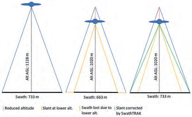
Figure 4: An example of an original flight plan (left), a reduced flight plan due to cloud cover (centre) and an actual swath thanks to the expanded FOV shown in green (right) – not to scale.
related to gaps and reduction in coverage rate. With dynamic FOV, the operator did not have to waste time remaking the flight plan each morning and the analyst was able to streamline the data, which was of consistent coverage and density. Despite the challenges posed by the clouds, the team flew every planned flight while maintaining the desired point density and an average absolute accuracy of 8cm off of ground control. STI’s client, who had accompanied the team on one of the flights and was familiar with the challenges posed by the local weather conditions, was very happy when presented with the final results. According to the team’s own estimate, without the flexibility of using SwathTRAK it would have taken twice the time and effort to complete the project. Ultimately, the Galaxy PRIME’s built-in feature enabled the project to be completed on schedule and on budget, despite the cloudy conditions.
ABOUT THE AUTHOR
Sumona Datta started her career as a journalist in Mumbai, India. She has since been associated with the Lidar industry for over two decades and is currently the media relations and content creation manager for Teledyne Imaging. sumona.datta@teledyne.com
Save time and money with Applanix Direct Georeferencing
Ditch Ground Control Points and reduce image overlap Speed up data processing with POSPac MMS/POSPac UAV software Survey hard-to-reach areas with ease
Applanix User Group Meeting and Conference
September 20-22, 2022 | Fremont, CA, USA Register now at info.applanix.com/ugm2022
Applanix Corporation 85 Leek Crescent, Richmond Hill, ON L4B 3B3 Canada T +1-905-709-4600, F +1-905-709-6027 info.applanix.com/airborne-video


