9 minute read
State of the Art in Multibeam Echosounders
The Evolution of a Bathymetric Workhorse
State of the Art in Multibeam Echosounders
Although the single beam echosounder is still in use, it has over the last 25 years gradually been replaced with new and less expensive multibeam echosounder (MBES) systems. And, although some side-scan sonar (SSS) systems also offer bathymetry, the MBES is the go-to system when it comes to bathymetry today. MBES technology has gone through an evolution rather than a revolution in recent years. In this article, we focus on the current state of the art for this bathymetric workhorse.
The MulTibeaM echosounder
The main function of an MBES is to detect a number of depths along a swath of bottom. To obtain these depths, the transducer sends out a pulse of sound that is reflected off the bottom and received by an array of transducers in a certain angular sector or swathe. The system has a single transmit beam and a number (often 256) of receive beams. The receive beams are formed on reception (and not, as some think, on transmission). The swathe angle varies per system but is generally somewhere between 120° and 170°, giving swathe widths on the bottom in the order of 3.5 to 25 times the water depth.
Most MBESs are ‘shallow-water’ MBESs, with ranges between a few tens of metres and a few hundreds of metres. A modern shallowwater MBES has a weight of a few kilograms up to tens of kilograms and can be installed on a surface vessel, ASV, AUV or ROV. Although large and heavy special deepwater versions with ranges up to full ocean depth are also available, the ‘basic’ MBES is described below.
daTa densiTy
An MBES is not only about measuring depth; it is about measuring as many depths as possible with a high accuracy and resolution. The resolution is defined by the across- and along-track beam angles. That beam angle in turn defines the ‘footprint’ from which the depth for that beam is returned. Modern MBESs have beam angles between 0.3° and 4°.
The beam angle (and swathe sector) define the basic number of depths that can be measured. Depending on the set-up, these depths are
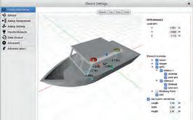
Parameters of a Multibeam Echosounder.
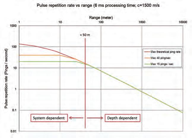
Depth-dependent update rate.

measured in ‘equi-angular’ or ‘equi-distant’ mode. Equi-angular means that all the beams have the same angle and that the footprint varies. In equi-distant mode, the footprint is kept constant but the beam angle is reduced.
Most modern MBES systems offer more than the ‘base’ number of points per swathe. Often, this is done by creating overlapping beams (of the base beam angle) and measuring depths for the intermediate beams. The number of depths is thus increased; depending on the bottom and implementation in the MBES, more detail can be shown with up to 1,024 depths per swathe.
The final data density is defined by the number of beams (depths) and the ping rate, or the number of swathes that the MBES can measure per second. The ping rate depends on the water depth, but can be as high as 60 pings per second in shallow water.
accuracy
For nautical charting, the Special Publication 44 of the IHO sets the standard for sounding accuracy to which an MBES should adhere (together with the other sensors). Some countries, and especially the offshore and dredging industry, do not find the S44 standards strict enough and impose their own accuracy standards on the work to be performed.
For the MBES to meet these standards, it not only needs to give full bottom coverage (sounding density) but also to measure each depth point with a minimum accuracy. That accuracy depends both on the local situation and, more specifically, the sound velocity and the pulse length of the system.
Where in the past the transmitted signal was a ‘continuous wave’ (CW), a modern MBES can often also transmit what is called an FM or CHIRP (Compressed High Intensity Radar Pulse) signal. The main advantage of the CHIRP is a longer range with better range resolution. For a CW type MBES, the range resolution is defined by the pulse length of the signal, whereas for a CHIRP type MBES the range resolution is defined by the bandwidth of the signal, allowing longer pulses and therefore more power to be transmitted. For a high frequency, shallow-water FM MBES, the range resolution is sub-centimetre for short ranges, allowing high accuracy for the sounded depths.
Frequency
The capabilities and dimensions of any acoustic system are mainly defined by physics. Underwater acoustics tell us that a high frequency will have a smaller range than a low frequency system. However, a high frequency system can, at a given size, produce a smaller beam angle than a low frequency system. Also, frequency dictates whether the system can penetrate the top layer of the sea bottom or will be reflected by it. Finally, the frequency defines the smallest possible pulse length or bandwidth.
As can be seen, beam angle, size and range are all a function of frequency and counteract each other. As such, there is no ideal frequency. For highly detailed, close range bathymetry, a high frequency system will give the best results in a relatively small form factor. For full ocean depth bathymetry, a low frequency needs to be chosen; if a small beam angle is then required the transducer will become large (and heavy). In

Maximum range depending on frequency, power and pulse length.
general, shallow-water MBESs operate at a frequency between 100 and 700kHz, which reflects off the top of the sea bottom but generally does not penetrate it.
To counteract frequency limitations, most manufacturers now offer shallow-water MBESs that are frequency-selectable. That is, the MBES can be tuned to a specific frequency in the range of 100–700kHz. Of course, the above remains true and the specifications of the MBES therefore change with a different frequency.
MulTi-Frequency and MulTi-ping
Some manufacturers allow the user to not just select a single frequency but to use multiple frequencies simultaneously. Although all the previous limitations still hold, using multiple frequencies can reduce the amount of noise encountered. So, rather than not having some (high frequency) depths, these data points can be filled in using lower frequency data (although with a larger footprint and thus showing less detail).
Another option for especially deepwater MBES is the use of multi-ping. In this situation, two to four pings are transmitted at slightly different angles simultaneously. This counteracts the long travel times of the signal in deep water and allows for greater coverage without gaps at higher survey speeds.
WaTer coluMn daTa
A traditional MBES measures a single depth per beam per ping. In general, the ‘first depth strong enough to be detected’ will result in the depth displayed. Less strong depths that may be closer to the multibeam are not detected. Also, a strong reflector close to the transducer may give a depth rather than the weaker bottom below it.
Many modern MBES systems circumvent this limitation by offering water column data as an option. With this technique, the water column of each beam is divided into a number of ‘bins’. The MBES now looks for a return within each bin for each beam for each ping. This allows the MBES to measure multiple reflections and thus create 3D images of objects in the water column (or to see the bottom through, for example, vegetation). Some manufacturers even support multi-frequency in combination with water column data, allowing even more objects to be positively detected.
As can be deduced, especially with many beams, multi-frequency and a high ping rate make the amount of data gathered enormous. To compensate, the water column data is often compressed to make it manageable. Despite this, the data volumes (and thus the time spent processing) are still large.
backscaTTer daTa
Backscatter is the amount of signal returning from the bottom. Depending on the type of material, more or less signal will be received thus allowing object and bottom classification. Most modern MBES systems have the option to receive backscatter data together with the depth information and show an SSS-like image.
Some manufacturers combine the backscatter data with both water column and multifrequency capabilities, allowing even more information to be collected. The advantage of combining backscatter with water column data is that objects in the water column can be better identified. The combination of backscatter with

Water column data. (Image Courtesy: QPS.nl)

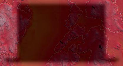
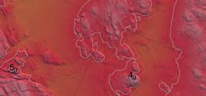
Multibeam vs. SSS backscatter.
multi-frequency is especially useful for bottom classification. As materials can react differently to different frequencies, measuring the backscatter at different frequencies but at the same moment in time can give classification algorithms better information to work with.
sss vs MulTibeaM echosounders
With the backscatter option on the MBES, a common question is whether an SSS is still required. As described in an earlier article on SSS technology, the brief answer is that it is. The difference between MBES backscatter and a true SSS is that the MBES will provide one backscatter value per beam, whereas the SSS will provide an almost continuous signal, thus giving a higher resolution. So, an MBES provides at most around 1,024 backscatter points per swathe, whereas an SSS has a continuous signal. However, the MBES data may be more than enough for a general classification. If, however, more detail is required, it is advisable to use an SSS.
oTher opTions
Besides the options described above, manufacturers offer additional options in their systems. An example is a dual head set-up. With this option, a much larger swathe can be created with swathe angles up to 240°, allowing surface to surface measurements for inspection work. The dual head option is often used in pipeline inspections. Some manufacturers also offer a pipeline mode, where a small sector beneath the transducer gives highly detailed information (at a high frequency).
Another option often offered is the integration of an Inertial Motion Unit (IMU) with the MBES. This is often advertised as not needing any calibration, although most manufacturers mean that there is no additional calibration required between the MBES and the IMU. Performing an MBES calibration will also give the IMU calibration parameters. Sometimes ignored is the fact that the IMU also plays a role in the positioning system. This means that, even though the values can be obtained from the MBES calibration, they still need to be entered into the survey software to compensate for any positioning offsets.
Huibert-Jan Lekkerkerk is a contributing editor, freelance hydrographic consultant and author of other publications on GNSS and hydrography and principal lecturer in Hydrography at Skilltrade (Cat B) and the MIWB (Cat A). info@hydrografie.info
Making Hydrographers’ Tasks Easier


