5 minute read
WHAT IS A HEAT PUMP?


So, where did the term “Heat Pump” come from anyway???
The invention of the heat pump has been credited to American inventor Robert C. Webber, and it was quite by accident that the concept for the heat pump was discovered. In the late 1940’s Webber was experimenting with his deep freeze and, get this, as legend goes he accidentally touched the “outlet pipes of the cooling system” (the discharge line) and burned his hand. You can almost see the light bulb going off in his mind
Webber decided to see if the mechanics could be reversed. Some minor modifications were in order for the ol’ deep freeze unit, as sources on the internet explain: “He connected the outlet piping from a freezer to a hot water heater and, since the freezer was producing a constant excess heat, he hooked up the heated water to a piping loop.” A small fan was used to transfer the heat from the hot water to the air, and voila the heat pump was born.
According to Lord Kelvin’s Second Law of Thermodynamics, heat will always travel from a warmer area to a colder area. Webber saw this as “pump - ing” heat from a warmer area to a colder area, hence the “heat pump”.
After he saw that his invention was successful, he built a full-size heat pump to provide heat for his entire home. His design used copper tubing buried in the ground through which he ran refrigerant to gather the ground heat. The gas was condensed in his cellar, providing heat for the entire house.
Now, taking Webber’s initial idea and applying it to a typical air-conditioning unit—with the addition of a few modifications—you have the modern residential/commercial heat pump.
Utilizing Kelvin’s Second Law of Thermodynamics, the process of blowing warm air through a fin-tube coil, with a cold fluid (refrigerant) flowing through the tubing, will result in heat transferring from the air to the fluid. This lowers the temperature of the air in the conditioned space and the result is what we know as “cooling”.
The goal of the vapour compression cycle used in a refrigeration/air-conditioning system is to provide a continu - ous source of cold liquid refrigerant to a fin-tube coil (evaporator), which will result in a continuing ability to transfer heat from the refrigerated space.
A basic review of the cycle:
1.Low pressure superheated refrigerant vapour, containing the heat from the refrigerated space, flows from the evaporator into the compressor.
2. The compressor “compresses” the vapour into a high-pressure vapour.


3. The compression process adds heat to the refrigerant vapour, resulting in a high temperature (superheated) high-pressure vapour leaving the compressor.
4. The superheated refrigerant vapour exits the compressor and flows into a fin-tube coil (condenser). Air flows through the condenser, transferring vapour’s heat content to the air.
5. The temperature of the superheated high-pressure vapour is reduced and experiences a phase change into a warm liquid.
6. The warm liquid flows to the expansion device and experiences a pres - sure drop. This lowers its temperature to the saturation temperature corresponding to the lower liquid pressure. 7. This low pressure/low temperature saturated liquid flows through a fintube coil (evaporator) located in the refrigerated space. Air in the refrigerated space is transferred to the liquid refrigerant, causing a change of state into a vapour. All of the liquid should change state to a vapour prior to exiting the evaporator tubing, resulting in a cool vapour flowing to the compressor inlet.
Simply put, the cycle transfers heat from the refrigerated space to the refrigerant. In order for the vapour compression cycle to be an endlessly repeating cycle, the heat from the conditioned space has to be transferred away from the refrigerant. This occurs at the condenser, located in a space where the temperature is of no concern (outdoors). The refrigerant can then again start the cycle to allow it to be used to transfer heat from the refrigerated space, over and over.
A standard air conditioning system transfers heat from the conditioned (re - frigerated) space, lowering the temperature in the space. That heat transferred to the refrigerant, plus the heat added to the refrigerant during the compression process, is transferred to the outdoor air via the condenser.
The heat pump also transfers heat from the conditioned space, but in a heat pump application the conditioned space is now outdoors. So, the evaporator is now located outdoors. The heat transferred to the refrigerant in that process, plus the heat added to the refrigerant during the compression process, is transferred to the air in the conditioned space via the condenser.
So, the heat pump is nothing more than the basic vapour compression cycle utilized in an air conditioning system, with added controls and valving to allow the system to either remove heat from the conditioned space (and transfer it to the outdoors), or remove heat from the outdoors (and transfer it to the conditioned space).
As such, rather than a distinct evaporator and condenser, we now have two dual purpose coils…an “indoor” coil and an “outdoor” coil.
Same vapour compression process, but the evaporator and condenser have changed places. We’re removing heat from outdoors and transferring it inside.
When the conditioned space requires cooling, the indoor coil functions as the evaporator, and the outdoor coil functions as the condenser, and when the conditioned space requires heating the refrigerant flow is reversed, allowing the discharge from the compressor to flow to the indoor coil, where it functions as the condenser. Reversing the refrigerant flow is accomplished with a four-way reversing valve (see Figure 1).
The reversing valve is located in the discharge line between the compressor outlet and the outdoor coil inlet. A solenoid coil (not shown), when energized, allows the reversing valve to “shift” from one position to another.
In the de-energized mode the refrigerant flows from the compressor discharge port to the inlet of the outdoor coil. The other two ports allow the refrigerant vapour from the indoor coil to flow to the compressor suction port (see Figure 2).
When the temperature in the conditioned space falls below the minimum heating temperature setting of the thermostat it will cause the following sequence of events to occur:
1.With the thermostat set in the heating mode the reversing valve will be energized.
2. The “Y” terminal on the thermostat will supply power to the compressor contactor, starting the compressor and outdoor fan.
3. The “G” terminal on the thermostat will supply power to the indoor coil blower motor, starting the motor. The unit is now in the heating mode, and the refrigerant flow through the reversing valve is shown in Figure 3.
THERE’S MORE
There are several other modifications required in the refrigerant circuit to allow for the trouble free reverse flow required in a heat pump:
Liquid Filter-Drier: The filter-drier should be mounted in the common liquid line between the indoor coil and the outdoor coil. Given the nature of a heat pump, liquid refrigerant will flow from the outlet of the outdoor coil to the inlet of the indoor coil during the cooling mode, and from the outlet of the indoor coil to the inlet of the outdoor coil in the heating mode.
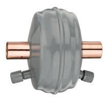
As such, a standard filter-drier cannot be used in this application. It will need to be a special filter-drier capable of removing system contaminants regardless of which direction the refrigerant is flowing—a bi-directional filter drier (see Figure 4).
Bi-directional flow is accomplished with a series of check valves at each end of the filter-drier housing. They allow re -