5 minute read
Efficient Electronics Cooling: Using Boiling Process for CPU Cooling (Campus Feature


Efficient Electronics Cooling: Using Boiling Process for CPU Cooling
By Aranya Chauhan
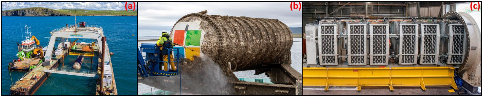
In today’s world we feel connected to people around the world because we have a reliable internet connectivity. Science and engineering have made significant developments and made 24x7 internet access a reality. But what is the source of internet? What is a cloud, where all our data is stored? All this infinite information on Google, where is it coming from? The simple answer to all these questions is Data Center. A data center is a building where thousands for servers are stored, these servers are responsible for never-ending flow of information across the internet. All the big technical companies, Google, Microsoft, Amazon, Facebook, have their data centers continuously transferring and storing information. A data center contains thousands of Central Processing Units (CPUs), each CPU acts like a small brain. One or more than one CPUs are installed in a server along with other electronic equipment like memory and storage devices. These servers are stacked in a pile to form a rack and hundreds of racks are installed in a room. Now such combination of rooms forms a data center. We have all experienced how our laptops and desktop computers become hot after using for some time, sometimes even mobile phones. And at some point, we have all heard fan noise coming from our computers. That time, the computer fan is trying to tell us that CPU is generating lot of heat and in some cases, we can feel the heat. That is the reason advanced gaming computers are built with effective cooling systems, like pumped liquid cooling because air cooling is not enough to provide efficient cooling. Now imagine thousands of such CPUs are generating heat in a data center, and these CPUs require lot of cooling. In 2018, Microsoft conducted experiment by sinking a data center unit in the ocean since heat generation in servers is expected to increase significantly in next few years. Figure 1 shows the data center unit which was installed at the bottom of the Scottish sea.

Figure 1: Microsoft's underwater data center experiment, (a) Retrieving the data center unit from the sea, (b) Cleaning the unit, (c) Layout of racks inside the data center. (Source of images - https://news.microsoft.com/innovation-stories/project-natick-underwater-datacenter/)
The data center operation is a very energy expensive process. According to the report of Natural Resources Defense Council in partnership with Anthesis, in 2013 about 3 million computer rooms in data centers used enough electricity equivalent to annual output of 34 large coal-fired power plants. In 2018, worldwide data centers consumed 205 terawatt-hours of electricity, which is equivalent to 1% of total worldwide electricity consumption. A significant amount, ~40% of total power consumed by data centers is used for cooling operations, and 50 – 80% of this power is spent on CPU cooling. The conventional air or liquid based singlephase cooling techniques are not efficient to dissipate heat from high powered CPUs in data centers. The futuristic approach is to use two-phase (boiling heat transfer) cooling approach. During boiling the liquid absorbs heat and is converted into vapor phase. This liquid to vapor conversion uses latent heat of liquid, and this phenomenon can transfer significantly higher heat fluxes compared to single-phase heat transfer. The boiling heat transfer research conducted at Thermal Analysis Lab in Rochester Institute of Technology has developed an innovative tapered microgap evaporator to cool CPUs. The liquid-vapor flow mechanism during boiling heat transfer in the evaporator is shown in Fig.2.
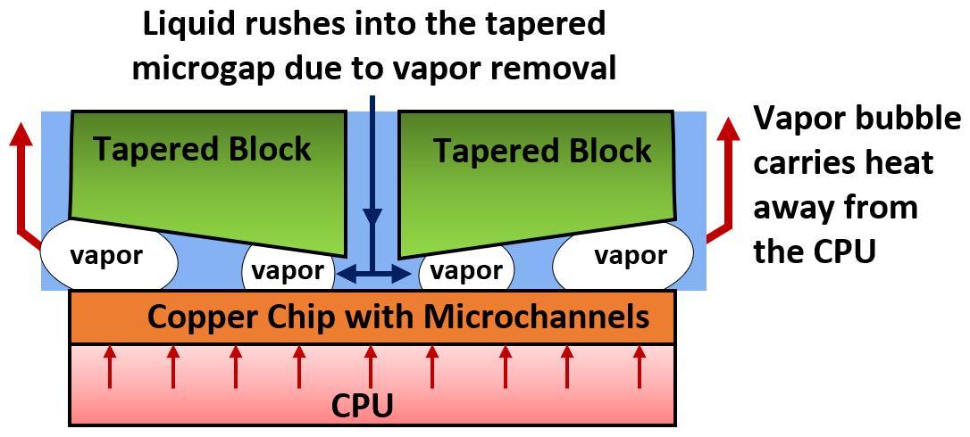
Figure 2: Vapor bubble formation, vapor removal, and liquid inflow mechanism in a tapered microgap during CPU cooling process.
A copper chip with microchannels is placed on the CPU to conduct heat from the CPU to the chip. A dual tapered block with two symmetric tapers is placed over the chip, this creates an expanding microgap between the chip and the block. As shown in the figure, during boiling the vapor bubble nucleates on the hot surface and continues to grow in the space. The growing bubble hits the tapered manifold block and expands along the increasing cross-section in the tapered microgap. The bubble continues to expand and leaves the microgap region with high velocities. This creates a liquid pumping effect, and liquid from the bulk is forced into the microgap for heat dissipation. This cycle continues and high heat fluxes can be dissipated reliably for long durations. The bubble visualization study was conducted at low heat fluxes to demonstrate this flow mechanism, and high bubble departure velocities ~ 1.1 m/s were achieved. The bubble departure velocity will increase at higher heat fluxes, hence higher liquid pumping is established at high heat fluxes. Such design is self-sustaining and does not require any external power for operation. This concept was employed in designing and building a CPU cooler prototype for data center application. An actual image of the prototype with dual tapered microgap is shown in Fig.3.
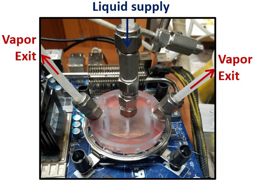
Figure 3: The picture of dual tapered evaporator in a thermosiphon loop during CPU cooling thermal test.
The cooler prototype was used as an evaporator in a thermosiphon loop configuration. Thermosiphon loop is a well-known heat transfer loop used in various cooling applications. It can transfer heat over large distances without requiring any external pumping power. The thermal tests were conducted using thermosiphon loop with tapered microgap evaporator, and the cooling performance of the loop was compared with a water cooler, and an air cooler. The thermal tests were conducted on a i7-930 processor with a thermal design power of 130 W. The baseline thermal testing was initially conducted, and later stress test was performed to mimic the high load conditions. During the stress test, the CPU was brought to its extreme processing power, and this was observed by recording a sudden increase in the CPU temperature. The cooling performance of three coolers was evaluated by comparing the ΔT value. The ΔT parameter is defined as the temperature difference between CPU and the chiller water. The heat absorbed from the CPU is eventually dumped in the chiller water for all three coolers. The lower ΔT value, represents higher cooling efficiency thus cooling cost is reduced. Thermosiphon loop obtained lower ΔT, therefore displaying superior cooling performance compared to the other two coolers. The ΔT values for thermosiphon loop, water cooler, and air cooler were 43°C, 56°C, and 74°C, respectively.
The thermosiphon loop can dissipate up to 280 W of heat from the CPU, and this value was obtained on a benchtop configuration where a mock CPU heater was used. This testing was conducted to showcase the heat dissipation ability of the dual tapered evaporator for futuristic high power density CPU cooling applications. Currently work is under progress to further increase the efficiency and maximum heat dissipation value of the dual tapered evaporator. q
Author Bio: Aranya Chauhan is Ph.D. in Engineering Candidate in Mechanical Engineering Department at Rochester Institute of Technology. His research is focused on fundamentally exploring efficient cooling solutions for high power density applications and developing protypes for industrial applications. He has published several research papers and obtained a provisional patent which is under process for final grant.


