STEP BY STEP
ONE STEP CLOSER TO EFFECTIVE VENTILATION

STEP BY STEP - ONE STEP CLOSER TO EFFECTIVE VENTILATION
www.ostberg.com
WHY VENTILATION?
WHY VENTILATION?
VENTILATION PRINCIPLES
DUCT SYSTEMS
DIFFERENT TYPES OF FANS AND AIR HANDLING UNITS
FLOW REGULATION
DIFFERENT VENTILATION SOLUTIONS
READING CATALOGUE DATA
CALCULATION EXAMPLES DEFINITIONS
GUIDELINES AND TROUBLESHOOTING
GLOSSARY
CONCLUSION
1

4
WHY VENTILATION?
This handbook is yet another step in Östberg’s effort to give everyone the possibility of clean indoor air. We know that good ventilation is important for good health and well-being, and to ensure that our homes are not damaged by moisture and mould. Many of our customers share our interest in good ventilation and want to learn more about it.
This book is structured in several stages, ranging from the basics of a good ventilation system and various ventilation principles, to how to use our products most effectively and how pressure drop and sound calculations are made. The final sections describe certain elements in more detail and use charts, tables and Mollier diagrams to further describe the properties of air and ventilation.
We also demonstrate the benefits of energy recovery using several calculation examples. The rising cost of energy makes this quite interesting reading. We hope that this book will serve to increase both your interest in and your understanding of good ventilation and what is required to achieve it.
1 5
A GOOD INDOOR ENVIRONMENT
Ventilation serves several purposes: it ventilates away impurities from building materials, excretory products from humans, moisture, bad odours, cooking odours and harmful substances (such as radon), and replaces these with fresh air. Minimum requirements for airflow are often specified in national housing standards. The design flow for each specific house, however, depends on how the building is used and by how many people. The majority of studies show that inadequate ventilation leads to health complications such as asthma, allergies, poor sleep and difficulty concentrating. Excessive amounts of radon can even cause cancer.
OXYGEN NEEDS
A person at rest breathes 4-6 litres of air every minute. During heavy physical exertion, these figures can increase to 100-120 litres a minute. Oxygen is required to oxygenate the body’s cells. The lungs then

6
ventilate out the carbon dioxide and water that is formed during the body’s metabolic process. This is a vital process to maintain proper body function.
RESIDUAL PRODUCTS
Building construction materials can include a number of different materials that over time secrete particles and gases that are detrimental to health and need to be removed from the building. Furniture and textiles may also contain various types of substances to make them more fire-resistant and stain-resistant.
Different types of plastics contain softening agents and solvents that are not good for human health.
Human beings produce carbon dioxide as a waste product during the metabolic process. A high concentration of carbon dioxide in the air we inhale makes us tired and have difficulty concentrating

1 7
HOME 100 M2 4 people: Supply air 9 l/s per person (minimum flow rate

BEDROOM: Supply air 4 l/s per person
KITCHEN: Exhaust air basic flow 10 l/s + cooker hood boost 75% smoke/odour
BATHROOM 10 M2: Exhaust air 20 l/s: (15 l/s + 1 l/s x m2 for areas larger than

LAVATORY: Exhaust air 10 l/s
CLOSET 6 M2: Exhaust air 2.1 l/s (larger than 1 m2: Exhaust air 0.35 l/s x m
CLASSROOM: Supply air 8-10 l/s per person (20 pupils = 200 l/s) (max 1000
MOISTURE
Moisture enters our homes through washing, bathing and cooking, but the air we breathe out also contributes to increased moisture content in indoor air. Too much moisture can lead to mould and also stimulates the growth of mites, which in turn are allergy-inducing.

SURPLUS HEAT
A good indoor temperature contributes to increased comfort and productivity. Designing ventilation to remove a portion of the surplus heat is a good investment.
DESIGN REQUIREMENTS FOR VENTILATION
Some of the minimum airflow requirements in force in Sweden are shown here as examples.

0 2 4 6 8 10 12 8
0.35
0.35 l/s x m2) (0.5 air change rate) smoke/odour extraction than 5m2) m2) 1000 ppm CO2)
When planning and designing ventilation, heating, etc., you must refer to the laws and ordinances in force in your own country. BBR* stipulates that the minimum flow rate for home ventilation systems in Sweden be set so that the air is replaced at a rate of 0.5 times per hour. If the home is used by a large number of people or sees a great deal of activity, however, this figure will not be sufficient to maintain a good indoor environment.
BBR gives the following advice “Planning and design should take into account the effect of occupancy rates, activities, additional moisture, and emissions from materials, ground and water.”
If the building is not in use for a period of time during the day, the quantity of air may be reduced, though may never be less than 0.1 l/s x m2.


12 14 16 18 20 22 l/s 1 9
* Swedish Building Regulations or BBR
VENTILATION PRINCIPLES
STEP BY STEP - ONE STEP CLOSER TO EFFECTIVE VENTILATION
www.ostberg.com
VENTILATION PRINCIPLES
DUCT SYSTEMS
DIFFERENT TYPES OF FANS AND AIR HANDLING UNITS
FLOW REGULATION
DIFFERENT VENTILATION SOLUTIONS
READING CATALOGUE DATA
CALCULATION EXAMPLES DEFINITIONS
GUIDELINES AND TROUBLESHOOTING
GLOSSARY CONCLUSION
2

VENTILATION PRINCIPLES
The function of ventilation is to provide fresh air wherever people are present. In homes, fresh air is supplied to the living room and the bedrooms. The used air is directed away from areas such as bathrooms, laundry rooms and kitchens. To ensure good ventilation, you must choose the right ventilation principles. This means that all areas must be ventilated using the correct airflow, regardless of external circumstances.
13 2
FRESH AIR
RECIRCULATED AIR
EXHAUST AIR
SUPPLY AIR
EXTRACT AIR
TRANSFERRED AIR
SUPPLY AIR
EXTRACT AIR
TRANSFERRED AIR
VENTILATION TERMS
FRESH AIR SUPPLY AIR
VENTILATION TERMS

EXTRACT AIR
EXHAUST AIR
Air travels through a building on a path from clean areas to areas that are less clean.
To ensure that the air travels the path it is supposed to (regardless of ventilation principles), transfer air devices or slots in the bottom of doors are required. This helps to optimally utilize the outdoor air supply.
14
SUPPLY AND EXHAUST AIR VENTILATION WITH ENERGY RECOVERY
With rising energy prices and an increased demand for energy recovery, this type of ventilation should be the primary option in new installations. Supplying filtered and tempered fresh air to the occupied zone without draught, and with flows adjusted for both supply and exhaust air, these systems are also best in terms of comfort. These units also often have the option of demandcontrolled ventilation, i.e. a higher flow when necessary and a minimum flow when possible. In addition to all these other benefits, the systems also recover heat/cold in the exhaust air. Energy recovery can take various forms, but recovery rates in rotating heat exchangers can be up to 86%. This means that 86% of the energy – in the form of either heat or cold – in the exhaust air is recovered and transferred to the supply air. This system thus works just as well for therecovery of cold and can, for example, be used when there is a separate cooling system in the home and the indoor temperature is lower than the outdoor temperature. In certain circumstances, the rotating heat exchanger can also transfer moisture. This is particularly advantageous in countries with cold climates, where during the winter it is desirable to retain and restore moisture in the indoor air that could otherwise become quite dry. Operating costs derive from the energy consumption of the fans and the energy loss from the heated exhaust air that is not recovered (approx. 15%).

15 2
ENERGY RECOVERY FRESH AIR EXHAUST AIR EXTRACT AIR SUPPLY AIR EXTRACT AIR SUPPLY AIR TRANSFERRED AIR TRANSFERRED AIR
SUPPLY AND EXHAUST AIR VENTILATION WITH ENERY RECOVERY
SUPPLY AND EXHAUST AIR VENTILATION
In this system, both the exhaust air and the supply air are fan controlled. This means that flow can be adjusted on both the supply air side and the exhaust air side, i.e. you can control both the flow and where you want to have it. This system can be equipped with filters and cooling or heating coils to heat/cool the supply air. This provides a high degree of comfort.The disadvantage is that energy recovery from the exhaust air is not possible.Operating costs derive from the energy consumption of the fans and the energy loss from the cooled/heated exhaust air (100%).
EXHAUST AIR VENTILATION
This type of ventilation is commonly found in older constructions. The system consists of a duct system for exhaust air with a fan to ensure an even and adjustable airflow. Fresh air is supplied to the rooms unheated and unfiltered through openings above the windows or in walls. Because the air just takes the simplest route into the building (open windows, places that are not sealed correctly), it is difficult to control where the air enters the building and therefore to adjust air volume.There is therefore a great risk for draughts and inflow of cold air in countries with cold climates.
Another drawback is that it is not possible to recover energy from the exhaust air Operating costs derive from the energy consumption of the fans and the energy loss from the heated/cooled exhaust air (100%). One variant of exhaust air ventilation is the exhaust air heat pump.


16
SUPPLY AND EXHAUST AIR VENTILATION
EXHAUST AIR
EXTRACT AIR
EXTRACT
FRESH AIR
TRANSFERRED AIR SUPPLY AIR
SUPPLY AIR
AIR
This type of system works in the same way as a regular exhaust air ventilation system, but also uses heat pump technology. The heat in the exhaust air is recovered in the heat pump and transferred to a tap water system or a heating system. Operating costs derive from running the heat pump and from the heat that is not recovered (100%).
NATURAL VENTILATION

The simplest type of ventilation, natural draught, has been used throughout history. In its earliest forms, natural ventilation consisted of a hole in the roof or wall to direct smoke out of the structure. Ventilation shafts later came into use. Natural ventilation is based on differences in air density at different temperatures. The drawback is that temperatures vary throughout the day, and particularly with the seasons.This means that the ventilation airflow fluctuates, and also that the flow is greatest when the difference in temperature is greatest, i.e. in the winter when it is cold outside and warm inside. It is not possible, in other words, to adjust airflow to the desired rate. Fresh air is unfiltered and is supplied to the room untempered through openings above the windows or in walls. There is therefore a great risk for draughts and cold air inflows in cold countries. The energy from the exhaust air cannot be recovered. Operating costs derive from losses from the heated/ cooled exhaust air that leaves the building (100%).
2
EXHAUST AIR VENTILATION FRESH AIR EXHAUST AIR TRANSFERRED AIR SUPPLY AIR EXTRACT AIR NATURAL VENTILATION EXHAUST AIR FRESH AIR SUPPLY AIR EXTRACT AIR SUPPLY AIR EXTRACT AIR SUPPLY AIR EXTRACT AIR TRANSFERRED AIR TRANSFERRED AIR TRANSFERRED AIR FRESH AIR FRESH AIR
DUCT SYSTEMS
STEP BY STEP - ONE STEP CLOSER TO EFFECTIVE VENTILATION
www.ostberg.com
DUCT SYSTEMS
DIFFERENT TYPES OF FANS AND AIR HANDLING UNITS
FLOW REGULATION
DIFFERENT VENTILATION SOLUTIONS
READING CATALOGUE DATA
CALCULATION EXAMPLES DEFINITIONS
GUIDELINES AND TROUBLESHOOTING
GLOSSARY CONCLUSION
3

DUCT SYSTEM
A duct system must meet the requirements set for the construction.
Duct systems lead fresh air to the areas fresh air is desired and evacuate the used air from other designated areas.
This places many demands on the duct system: It must be fully sealed, it must not generate noise and it must not cause unnecessary drops in pressure. It must also be possible to clean a duct system after many years of use. A duct system usually consists of several different components with various functions such as to filter, regulate, heat, cool and disperse air.
3
DUCT SYSTEM
A duct system can consist of a number of different components, each with its own function. However, they must work effectively together to meet the requirements of the construction. One thing that is very important to consider is the speed of the air through the duct system. High speeds create both noise and high pressure drop rates. High pressure drop rates mean that the fan has to work harder than what is actually necessary, which leads to higher power consumption.The rule of thumb is that the nearer the duct system is to the rooms it is servicing, the lower the flow velocity should be. In ventilation systems used in homes, speeds should not exceed 3 m/s, and no more than 2 m/s when a diffuser is used.


PRESSURE DROP
In order to be able to choose the correct unit/fan, a pressure drop calculation must be made on the duct system. A well-designed duct system with good components, which takes into account low speed in the ducts and low rates of pressure drop in the components (such as diffusers and grilles), is free from leaks, generates less noise and requires less energy to run. If you use spiral-fold sheet metal in the duct system, the manufacturer will provide information on pressure drop at different air velocities.
22 Ansl. dim.
Flow m3/s Static
Connection dim.
Example of pressure drop curve, here for a filter box.
pressure drop, Pa
DUCTS
Circular, spiral-fold ducts of galvanized steel sheet should be used if possible.

Ducts are connected to fans and other units in the system using duct components equipped with sealing rings to reduce vibrations and ensure good sealing. Where rubber seals are not possible, mounting clamps are used instead. Each of these prefabricated components, such as bends, bifurcations and connections, has its own pressure drop curve showing the pressure drop at different flow speeds.
If flexible hoses are used, these must be fully stretched and the bends must be wide and soft so that the pressure drop in the system will not be too high.
The ducts are hung or attached to the building in some other way (e.g. with perforated strip), and swing freely.
Ducts and duct components are attached to each other using riveted joints or approved screws/bolts to ensure that they do not glide apart.
23 3
Mounting clamp MK.
INSULATION
Insulation in ducts can serve several purposes: heating, cooling, protection from condensation, or fire-proofing. Different types of insulation are used for different purposes. Thermal insulation is used when warm air is transported in ducts that are routed to cold areas (attics, etc). The thickness of the insulation depends on the diameter of the duct and on the climate. Anti-condensation insulation consists of thermal insulation with an airtight top layer. This type of insulation is primarily used in ducts that transport cold air through warm areas. The insulation prevents condensation from forming on the exterior of the duct and risking moisture damage in the surrounding areas. In air conditioning systems, anti-condensation insulation is used in conjunction with thermal insulation.Fire insulation must be type-approved and the thickness of the insulation must correspond to the type-approval for the desired fire class for the insulated area. This type of insulation is used when the duct passes through a fire cell and in the insulation of exhaust outlet ducts such as kitchen flues.


SILENCERS
Silencers are almost always required in ventilation systems, as all fans generate noise. In most cases, the room(s) the duct is servicing or the surroundings (neighbours) will determine noise requirements. The most common type of silencer consists of a pipe or a box made of galvanized sheet steel that is insulated on the inside. These are fitted with circular or rectangular duct connections. The rectangular silencers also have internal baffles (walls) to improve sound attenuation. This capacity, however, depends on the length of the silencers and the thickness of the insulation. The silencers are placed between the fan and the areas being serviced. The pressure drop for circular silencers is usually negligible; when using rectangular silencers, you must refer to the manufacturer’s pressure drop diagram.
Silencers are also available as flexible hoses that are also insulated in the inside, but with a top layer of heavy plastic or thin fibreglassreinforced aluminium foil. These have poorer sound attenuation abilities than silencers made of steel sheet and as such, usually cannot replace these. However, they can instead be used as supplemental silencers in the duct system. The drawbacks of these silencers include pressure drops if they are mounted in sharp bends and a “leaking” of sound to the surrounding area. They should therefore not be placed in sound-sensitive areas.

Ansl. dim. 3
Static pressure drop, Pa Flow m3/s Connection dim.
Example of pressure drop for rectangular silencers.
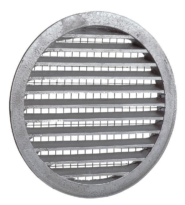
AIR INTAKE
Air intake grilles can be mounted to best advantage on the shadiest side of the building. To prevent noise and moisture accumulation through rain and snow, speeds should not exceed 1.5 m/s over the grille.

DAMPERS
The function of the damper in the system can vary. Dampers are used both as shut-off valves for outdoor air or smoke fumes from fires, and to adjust airflow. They all have different characteristics in terms of degree of sealing, temperature resistance and function. The most common type of damper in ventilation systems is the balancing valve. These are used primarily in slightly larger duct systems in which it is desirable to adjust air volumes individually in each section of ducting. Using dampers for throttling is not desirable, as this gives the fan a higher pressure to work against and thereby also increases energy consumption. In a well-balanced system, the grille is primarily used to measure the airflow. Balancing valves are almost never used in home ventilation systems, as these duct systems are so small and the flow is adjusted by the diffuser.
Air intake grille, YG.
DIFFUSERS
There are a number of different types of diffusers with different characteristics, and the choice of which to use depends entirely on your objectives and the placement options available. Diffusers are available for placement in ceilings, walls or floors. Floor diffusers are of the "displacement" variety. This means that fresh air is supplied at floor level, is heated in the room and then rises toward the ceiling where the exhaust air diffuser is located. Ceiling and wall diffusers are of the mixing system variety, in which fresh air is mixed with the air in the room and then directed out. Most ceiling and wall diffusers have adjustable distribution patterns and throw.Ceiling or wall diffusers are most commonly used in home ventilation systems. The objective is for the supplied air to have the longest route possible in the ventilated room without creating draught. Throw is often specified as L0.2 or L0.15, and the distances from the diffuser expressed in air velocity are 0.2 m/s and 0.15 m/s. These speeds should not be exceeded in the comfort zone (where people are present). Other properties that are important to consider when selecting a diffuser is how much sound the diffuser produces and how much pressure drop it generates.


27 3
Floor-installed diffuser with exhaust air diffuser in ceiling.
Ceiling and wallinstalled diffusers.
The filters are declared with both class and separation capacity in weight percent, where the percentage is rounded down to the nearest five. To be classified, a filter must separate at least 50% by weight of the particles in the size class.

Filterclass
*) 1 µm = 0,001 mm
FILTER
Filters with a higher efficiency removes more of the particulate contaminants in the air. At the same time filters should have a low air flow resistance to be energy efficient.
In residential ventilation it is important to remove as much as possible of particles smaller than 1 μm to obtain a high indoor air quality. These particles may come from combustion or traffic and can potentially cause harm to human health.

For more information on the current classification of filters see euroventcertification web.

28
Classification acc. to ISO 16890 ePM1 ePM2,5 ePM10 Coarse Efficiency 50-95 % 50-95 % 50-95 % No demand Particle size <1 µm* <2,5 µm* <10 µm* all sizes
HEATING COILS
There are two types of heating coils used in ventilation systems: electric or hot water. A heating coil heats the air that passes through it. The number of degrees the air is heated depends on the power of the coil. The heating coil must have some type of control so that the air can be heated to a set temperature. Pulsers are often used in conjunction with temperature sensors as controls for heating coils. The pulser releases voltage for different durations of time according to how many degrees the air needs to be heated. A heating coil should have some type of interlocking device so that the coil cannot be activated when there is no flow. The flow rate over aheating coil may not be too low either, because then the surface temperature on the coils will be too high. On water heating coils a control unit opens and closes a valve which increases and decreases the flow of hot water through the coil. A heating coil must be equipped with some type of anti-freeze device to protect the coil from freezing and causing water damage. Units with heat recovery may also require heating coils in very cold climates.


COOLING COILS
Cooling coils are not very common in ventilation in single family houses, but can provide a more comfortable indoor climate on warm summer days.
Water from downhole heat exchangers (geothermal heating), which maintain a temperature of 6-8°C, are often used instead of cooling coils in Sweden. To achieve a greater cooling effect, air volumes should be increased somewhat above normal levels.
The cooling coil must be equipped with a condensation water draining device, as the cooling coil also dehumidifies the supply air through condensation in the coil. Controls consist of a control unit with a temperature sensor that opens/closes a valve to adjust the flow through the coil (two-way valve) or increases/decreases the ratio of warmer return water to adjust the cold water temperature (three-way valve).
29 3
DIFFERENT TYPES OF FANS AND AIR HANDLING UNITS (AHU)
STEP BY STEP - ONE STEP CLOSER TO EFFECTIVE VENTILATION
www.ostberg.com
DIFFERENT TYPES OF FANS AND AIR HANDLING UNITS
FLOW REGULATION
DIFFERENT VENTILATION SOLUTIONS
READING CATALOGUE DATA
CALCULATION EXAMPLES DEFINITIONS
GUIDELINES AND TROUBLESHOOTING
GLOSSARY CONCLUSION
4

DIFFERENT TYPES OF FANS AND AIR HANDLING UNITS (AHU)
The fan’s role in the system is to put the air in motion, supplying the kinetic energy required for the air to reach the serviced areas by moving through the duct system and its components. The fan must meet many requirements: it must be energy-efficient, quiet, small and easy to install. It must also be inexpensive and have a long service life, with long intervals between required service operations.
33 4
CORRECT
The duct bend is aligned with the fan’s direction of rotation.
If flexible ducts are used, these must be fully stretched and the bends must be wide and soft.
If possible, the fan/unit should not be placed in direct connection to noise-sensitive areas such as bedrooms, living rooms, hobby rooms or offices.
It is very important to ensure that the fan is connected properly to the duct system, for reasons of both pressure drop and noise. If not connected correctly, noise levels could increase by 4-6 dB and pressure by several (or at worst, hundreds) of Pascals. Because the air velocity at the inlet and outlet of the fan can be relatively high, and the speed profile after the fan uneven, special care must be taken at bends and bifurcations. If possible, bends should be preceded by 4-5 diameters of straight duct, and the bend itself should be smooth and follow the direction of fan rotation.
34
The duct bend is far too sharp and too near the fan.
The duct bend is far too sharp and too near the fan, and does not follow the fan’s direction of rotation.
The duct bend does not follow the fan’s direction of rotation. The total sound level and pressure drop increases. If the fan is also turned in the wrong direction, sound levels increase even more.
A flexible duct with too many and sharp bends. The pressure drop increases.
The fan/unit must be installed in such a way that it is easily accessible for cleaning and service.
The unit and larger fans must be installed so that structure-borne sound cannot be transmitted. These should be placed on thick sheets of insulation or on vibration dampers.
Wall-mounted units must be fitted with vibration damping mounting devices.
If the fan distributes dirty air, a filter should be installed before the fan, as this will increase the service life of the fan and help prevent the impeller from getting dirty and impairing fan function.
35 4
The duct bend is too near the fan.
INCORRECT
DIFFERENT TYPES OF FANS
Generally speaking, there are three main groups of fans: Centrifugal, axial and tangential. The most common fans used in ventilation are centrifugal fans with either backward or forward curving blades. In addition to impeller size, fan rotation speed (rpm) is a determining factor in the resulting pressure and flow. High rotation speeds lead to high flow and pressure, but higher rotation speeds also generate more noise and consume more energy.
CENTRIFUGAL FANS
In a centrifugal fan, the air stream is angled 90°, the supply air enters in an axial direction and leaves the fan wheel in a radial direction. There are two types of centrifugal impellers. The most common is the fan wheel with forward or backward curved blades. Centrifugal fans with straight blades are called radial fans and are common when particles are transported with the gas/air.

36
Centrifugal fans with forward curved blades must be combined with a scroll-shaped fan housing in order to run. The design of the scroll is very important to the fan's performance. For other centrifugal fans, the shape of the fan blades is the most determining factor in fan performance. A scroll is not required, but can be used to further increase fan pressure. Centrifugal fans are used almost everywhere gases are transported.
AXIAL FANS
Axial fans have an axial airstream and give relatively high airflows, but relatively low pressure rates and high noise levels. Axial fans are used where there is a need to transport a large amount of gas where there is a low pressure drop. Common uses are as cooling fans, drying fans, tunnel fans, etc. Axial fans are also used in conjunction with guide vanes in certain types of duct fans where the design of the guide vanes and impellers improve fan pressure. However, noise levels increase even more in this method. A major drawback of axial fans is that power needs increase with increasing pressure, which can cause the motor to overheat, for example when the filter becomes clogged.
TANGENTIAL FANS
Tangential (cross-flow) fans have a tangential airstream and are also used for transporting relatively large amounts of gas/air at low pressure. Tangential fans are compact in construction and work very well in small air curtains, etc.
37 4
DIFFERENT IMPELLERS (FAN WHEELS)
F-WHEELS
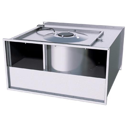
Fan impeller with forward curved blades are commonly called F-wheels. Fans with F-wheels provide a compact solution and are most competitive at relatively high pressures, where they also have their highest efficiency rates. It is important when choosing a fan with a F-wheel to ensure that it is correctly positioned in the area shown in the diagram. At low pressure and high airflow, an F-wheel requires a great deal of power from the motor, but the motors are often not designed for this. This is shown with a dotted line in the pressure/ flow diagram and referred to as “prohibited work area.” Within this area, the motor overheats very quickly. One drawback of F-wheels is that dirt and impurities easily get caught on the concave side of the impeller, which impairs capacity and can cause imbalance. If the wheel gets dirty, it must be cleaned, which can be rather difficult. A fan with a swing-out function makes this easier, however. F-wheels are used in several of our fans, including our LPK and RK duct fans, IRE insulated duct fan, RF and DF single and double inlet centrifugal fans, etc.
It is important when choosing a fan with an F-wheel to ensure that it is correctly positioned in the area shown in the diagram. At low pressure and high airflow, an F-wheel requires a great deal of power from the motor, but the motors are often not designed for this. This is shown with a dotted line in the pressure/ flow diagram above and referred to as "prohibited work area." Within this area, the motor overheats very quickly.
38 500x300 B3 ErP AC Ziehl RK 0500 1000 1500 2000 2500 0 50 100 150 200 250 300 350 400 00,1 0,20,3 0,40,5 0,60,7 PRESSURE/FLOW 0 200 400 600 800 1000 00,1 0,20,3 0,40,5 0,60,7 POWER SFP
Flow m3/s Total pressure Pa Flow m3/h
B-WHEELS
Impellers with backward-curved blades are commonly called B-wheels. If you choose a B-wheel fan for the same pressure and flow as an F-wheel fan, the B-wheel will be larger than the F-wheel. The advantage of choosing this type of fan is that B-wheel fans have higher efficiency rates, which means that the fan consumes less energy at the same pressure and flow. The B-wheel has the highest power consumption where the efficiency rate is best. Another advantage of B-wheel fans is that the impeller does not get dirty as fast as in F-wheel fans, and they are significantly easier to clean when they do. B-wheels are used in our CK, LPKB and RKB duct fans, IRB and RKBI insulated duct fans, RB single inlet duct fans, etc.

Fans with B-wheels have higher efficiency, which meansthat the fan consumes less energy at the same pressure and flow. The B-wheels has thehighest power consumption wherethe efficiency rate is best.
MIXED FLOW WHEELS
Mixed flow wheels (or diagonal fans) are a cross between axial and radial fan wheels. They have lower pressure and efficiency rates than centrifugal fans and lower flow than axial fans.
4
AIR HANDLING UNITS (AHU)
An air handling unit (AHU) is a composite machine with several different functions compiled into one unit. What components are used in the system depend on the end function desired. An air handling unit can consist of a filter component that cleans the incoming air, a cool/heat exchanger that recovers the energy that otherwise would have followed the exhaust air out of the building, and a fan component that transports the clean and heated/cooled air to the various rooms being serviced. The unit can also contain a heating coil or cooling coil for warming or cooling the supply air, as well as a damper that controls how much fresh air is let in. Larger units may also contain a humidifier, either on the exhaust air side for evaporative cooling or in the supply air side for humidification.

There are several types of heat exchangers, exchangers that also utilize the energy in the moisture (ERV, Energy Recovery Ventilation), and exchangers that only transfer heat (HRV, Heat Recovery Ventilation). If moisture transfer is desired, use a moisture transferring heat recovery system. A control system is necessary for the operation of the air handling unit. This system controls all functions, such as supply air temperature, and sounds an alarm if the system is not functioning properly or if it is time for service.
Many air handling units come pre-equipped with an integrated control system adapted to the specific model and functions desired.
40
HERU is a supply and exhaust air unit with heat recovery. Heru contains a filter with a high collection efficiency rate to separate pollen and other particles from the air, and a rotating heat exchanger energy recovery component with a high efficiency rate.
A built-in electric heating coil is included standard on most models. If a water heating coil or cooling coil is preferred instead, these are available as accessories for installation in ducts.
The fans used in the Heru units have high efficiency rates with EC motors. The Heru S model has 50 mm of insulation in the casing and can be placed in cold areas such as attics. Heru T must be placed in warm areas, such as in utility rooms or laundry rooms.

Heru is an air handling unit containing an advanced and integrated control system with many smart functions. It allows both constant supply air temperature and room temperature regulation. You can set it to reduce the temperature at night or provide demand-controlled ventilation via the CO2 sensor or humidifier. If you choose a unit with EC motors, you can also have constant flow. The unit’s flow can also be increased or decreased with a timer. The status of the unit, e.g. temperature and current operating mode, is shown continually in the remote control. The remote control can also be used to change all settings if necessary.
SAU is an air handling unit for only supply air without energy recovery. The unit contains a filter, a heating coil and a fan. The unit supplies filtered and clean air, heated via a water or electric heating coil, to the premises via an energy-efficient B-wheel fan with an external rotor motor.


4
HEAT EXCHANGER
A heat exchanger transfers energy in the form of heat between two media without mixing. In a ventilation system, heat is transferred from the exhaust air to the supply air, or the reverse if you would like it to be cooler inside than it is outside. There are two main types of heat exchangers: Regenerative (rotating) and Recuperative (plate/cross-flow).

REGENERATIVE
In regenerative heat exchange, the material in the exchanger is heated by a warm airstream (exhaust air) that is then transferred to a cold airstream (supply air), where it can emit its heat. Rotating heat exchangers are an example of regenerative heat exchange.
ROTATING HEAT EXCHANGER

A rotating heat exchanger consists of one corrugated and one smooth aluminium plate that are wound to a wheel. The air moves past the wheel through spaces. The wheel then rotates, with outdoor air on one half and exhaust air on the other half. The aluminium on one side is heated, and then cooled when it has rotated over to the other side. Heat recovery is controlled by the on/off switch or by controlling the rotation speed.

In cold weather, moisture is also transferred from the exhaust air to the supply air, which prevents the indoor climate from becoming dry. The temperature efficiency rate can be up to 85%. Specially designed rotors with moisture-transfer coatings are used for moisture transfer. These provide a moisture transfer rate of up to 90%, which can be compared to standard rotors that have rates of 50-60% when there is condensation in the rotor.
The rotors are also used in evaporative cooling, where the exhaust air is humidified and the input heat vaporization then lowers the temperature of the supply air by 3-5°C.
43 4
RECUPERATIVE
In recuperative heat exchangers, heat is transferred from the warm side (exhaust air) to the cold side (supply air) by directing the heat through the wall that separates the two media.
Plate/Cross-flow heat exchangers are one type of recuperative heat exchanger.
PLATE HEAT EXCHANGERS
A plate heat exchanger consists mainly of parallel aluminium plates, where the warm air passes on one side of the plate and the cold air passes on the other side. Heat is transferred through the plate. Moisture cannot be transferred and the temperature efficiency rate is 50-70%. To raise temperature efficiency, two exchanger units can be mounted one in front of the other.
44
Read more about calculating temperature efficiency rates and energy savings on page 98.

Condensation can occur in the heat exchanger and must then be conducted away. This condensation can cause the exchanger to freeze and can lead to reduced flow and function. This problem requires some sort of control to solve. One way is to reduce the supply airflow and thus heat up the exchanger with a larger proportion of exhaust air. Another way is to pre-heat the fresh air by placing a heating coil before the heat exchanger. Temperature is controlled via a bypass damper when the air is routed past the heat exchanger or in simpler constructions, where the exchanger must be taken out of the unit.

45 4
FLOW REGULATION
STEP BY STEP - ONE STEP CLOSER TO EFFECTIVE VENTILATION
www.ostberg.com
FLOW REGULATION
DIFFERENT VENTILATION SOLUTIONS
READING CATALOGUE DATA
CALCULATION EXAMPLES DEFINITIONS
GUIDELINES AND TROUBLESHOOTING
GLOSSARY CONCLUSION
5

FLOW REGULATION
Often, a fan's airflow needs to be regulated, either by setting it to the desired flow or by using some type of demand-control.
In demand control, a low flow is permitted to save energy when the premises are not heavily occupied, and higher flow is used when necessary. There are several different ways to regulate flow, but the most common is to change the voltage to the fan. In demand control, additional equipment may be required. This may comprise anything from a simple switch for manual control of fan speed to a regulator that continually adjusts the flow as needed.
49 5
AIR FLOW ADJUSTMENT BY REGULATING FAN SPEED

When altering the fan speed the air flow and pressure changes along the system line in the pressure vs. airflow diagram. EC fans are commonly used as they have considerably higher efficiency compared to traditional AC fans. In EC motors (electronically commuted) a rotating magnetic field is generated that drives an external rotor with permanent magnets without the use of any electrical connection to the rotor. The speed is regulated electronically from a 0-10 V input signal making integration to building management systems straight forward.
AIR FLOW ADJUSTMENT BY THROTTLING
The air flow can be adjusted by the use of dampers and valves. Using pressure sensors, EC fans can be regulated to give a constant pressure. To increase the pressure in the system in order to regulate air flow increases both energy use and sound levels.
50
TRANSFORMATOR OCH TYRISTOR

Traditional AC fans can still be used in applications where the efficiency is high enough. The speed of AC fans can be adjusted using transformers or thyristors. Reduction of the voltage can lead to increasing current which may affect current sensitive motor protection. The use of thyristors may lead to additional noise when strongly reducing voltage. Higher currents caused by voltage regulation causes additional generation of heat. A voltage regulated AC fan may therefore need lower air temperatures. Frequency regulated AC fans are not as common and requires EMC compliant equipment.


51 5
Transformator
Tyristor
EXEMPLES OF DIFFERENT VENTILATION SOLUTIONS
STEP BY STEP - ONE STEP CLOSER TO EFFECTIVE VENTILATION
www.ostberg.com
DIFFERENT VENTILATION SOLUTIONS
READING CATALOGUE DATA
CALCULATION EXAMPLES DEFINITIONS
GUIDELINES AND TROUBLESHOOTING
GLOSSARY CONCLUSION
6
FRESH AIR
SUPPLY AIR


EXTRACT AIR
EXHAUST AIR
EXAMPLES OF DIFFERENT VENTILATION SOLUTIONS
A ventilation system should be planned and designed according to the various requirements set by authorities, customers, etc. These requirements may concern minimum air quantity, noise, particulate matter efficiency, sealing and energy consumption. Requirements vary according to the type of premises and what activities are conducted there.
Below are some examples of solutions in various types of premises. To ensure the best ventilation, highest energy efficiency and lowest noise levels possible, it is important that the fans are installed correctly.
55 6
HOME EXHAUST AIR


120 m2: 0,35 x 120 = 42 l/s.


Bathroom 7 m2: 15 l/s + 2 = 17 l/s.
Laundry room: 15 l/s.


Kitchen: 10 l/s with boost to 30 l/s.
EXHAUST AIR
DIFFUSER


Damp and used air is removed via an exhaust air diffuser in the ceiling. The flow is set to the projected values.


FRESH AIR DIFFUSER

Fresh air enters the bedroom and living room through the fresh air diffuser.

AIR ROUTE

Air passes through the transfer air device or slot in the bottom of the door to bathrooms, lavatories, kitchens and laundry rooms.


56 Ø125
DUCTING


Ducting in the attic is thermal insulated to prevent condensation of warm and damp air in the ducts. NOTE: The duct from the cooker hood is an exhaust outlet duct and must be cleaned according to law. All ducts must be able to be cleaned.

CEILING FAN


TKC/TKS 300 B, TKV/TKH 300 B with ceiling duct. Easily opened for cleaning. Transformer controlled via cooker hood.

SILENCER


diameter Ø 125 mm, between fan and residence.


BASE FLOW
taken through cooker hood. Boosting the cooker hood opens the damper and/or increases fan speed.

57 6
BATHROOM, EXHAUST AIR
Approx. 7 m2: 5 m2=15 l/s + 1 l/s /m2 = 17 l/s.


SILENCER
diameter Ø 100 mm, 1000 mm long and 50 mm insulation.


OUTER WALL GRILLE

This installation requires a removable false ceiling for service and outer wall grilles of type YG 125.

AIR ROUTE
Air enters through the transfer air device or slot in the bottom of the door from adjoining rooms.


58
DUCTING

Ducting and fan are installed above removable false ceiling. The fan must be mounted able to be cleaned.


EXHAUST AIR DIFFUSER
Exhaust air diffuser placed farthest from the transfer air device or slot under door.
DUCT FANS

CK 100 A exhaust air fan with transformer for adjusting. LPK, LPKB or LPKBI are also excellent options in this application.

59 Ø100 6
HOTEL ROOM/BATHROOM, EXTRACT AIR
Approx. 8 m2: 5 m2=15 l/s + 1 l/s /m2 = 18 l/s


DUCTING
Fan and ducting are placed above removable false ceiling.
SILENCER diameter Ø 100 mm, 1000 mm long and 50 mm insulation.
DUCT FANS
LPK 100 A exhaust air fan with transformer/ thyristor.

LPKB or LPKBI are also excellent options in this application.


Ø100


60
AIR ROUTE


Air enters via the fresh air diffuser.

EXHAUST AIR DIFFUSER


Exhaust air diffuser placed farthest from the transfer air device or slot under door.


OUTER WALL GRILLE


This installation requires a removable false ceiling for service and YG 125 outer wall grilles.If the environment outside the outer wall grille is noise-sensitive, a silencer will also be required after the fan.
61 6
SERVER ROOM, EXTRACT AIR
Approx. 8 m2: For ventilating away excess heat
BASE FLOW
Airflow depends on power and temperature.
FRESH AIR DIFFUSER
YG 160 outer wall grille with VK multiple leaf damper on interior wall.


AIR ROUTE
Air passes the fresh air diffuser and out on the opposite side of the room to achieve good circulation and air mixture and to get out the warm air.
DUCT FANS
CK 100 A exhaust air fan with transformer for adjusting. LPK, LPKB or LPKBI are also excellent options in this application. For larger quantities of air and higher power, RK and RKB may be required.

62
WALL FANS
RS and KV are wall fans that are also good options in these applications.


CONTROL
The fans can be controlled via a thermostat start/stop or with a thyristor with temperature set point adjustment.

EXHAUST AIR
DIFFUSER
BSV grille.
63
6
Ø100
GYMNASIUM, SUPPLY AND EXHAUST AIR
520 m2 and approx. 156 people: 520 x 3,3 l/s = 1716 l/s.


Flow calculated based on 0.3 people /m2 and 800 PPM.
CEILING FAN


TKV/TKH 660 B3 EC, 1716 l/s at 70 Pa static pressure, with ceiling duct. Fitted with silencers or sound barriers. The ceiling fan is easy to open for cleaning.
EXHAUST AIR
Duct fan or ceiling fan.
DUCT FANS
Duct fan RKB 700x400 E3 EC, 1716 l/s at 140 Pa static pressure.
SUPPLY AIR
Large airflows require a supply air fan. Grilles in the ducts spread the air evenly in the rooms. A heater heating coil may also be required.


CONTROL
The fans are controlled by timers and/or CO2 sensors.
SILENCERS
LDR 800x500 mm, installed before or after fan.

EXHAUST AIR DIFFUSER
Damp and used air is removed via a centrally located exhaust grid. The flow is set to the projected values using the rotation speed fan controls.
65 6
HOME, SUPPLY AND EXHAUST AIR
WITH ENERGY RECOVERY
120 m2: min flow 0.35 x 120 = 42 l/s.


EXHAUST AIR 17+15+17=50 l/s.
Bathroom 7 m2:15 l/s +2=17 l/s.
Laundry room:15 l/s.

Kitchen: 17 l/s.
SUPPLY AIR 22+24 = 46 l/s.
Bedroom, 2 beds:10 l/s.
Bedroom, 1 bed:2x6 l/s.


Living room: 24 l/s
Outdoor air intake via outer wall grille YG 160.


DUCTING


Ducting in attics is thermal insulated to prevent condensation of warm and damp air in the ducts.

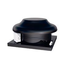
ROOF COWL
Extract air via TH 300 roof curb.
ENERGY RECOVERY UNIT
Heru® 100 T for installation in warm areas, such as laundry rooms.


SILENCER of diameter


Ø 125 mm, in steel sheet 1200 mm long with 100 mm insulation, and flexible silencer 600 mm long med 25 mm insulation.


66
OUTER WALL GRILLE
CEILING FAN


Separate exhaust air fan for cooker hood. TKC/TKS


300/400 B, TKV/TKH


300/400 B with ceiling duct. Easily opened for cleaning. Transformer controlled via cooker hood.
AIR ROUTE
Fresh air is supplied to the living room and the bedrooms. The air passes through the home and is removed in the bathrooms, lavatories, kitchen and laundry room.
SILENCER of diameter Ø 125/160 mm, between fan and residence.

DUCTING


The duct from the cooker hood is an exhaust outlet duct and must, by law, be cleaned. All ducts must be able to be cleaned.

COOKER HOOD


F251-16.
SUPPLY/ EXHAUST AIR DIFFUSER


Supply air via adjustable ceiling diffuser and with adjustable distribution pattern. Damp and used air is removed via an exhaust air diffuser in the ceiling. The flow is set to the projected values.


67 Ø125 Ø100 Ø125 Ø100 6
CLASSROOM SUPPLY AND EXHAUST AIR with energy recovery 16-20 pupils: SUPPLY AIR 20x8 l/s = 160 l/s.
EXHAUST AIR 160 l/s
EXHAUST AIR GRILLE
Internally insulated box with grille for exhaust air, 250x250 mm.

SILENCERS of diameter Ø 250 mm, in steel sheet 1200 mm long with 100 mm insulation and flexible silencer 600 mm long with 25 mm insulation.
ROOF COWL
Extract air via roof cowl TH 400.
WATER HEATING COIL
Duct-mounted water heating coil. Cooling coils are also available for installation in ducts if needed. HERU® has a control system for regulation.
ENERGY RECOVERY UNIT
HERU® 180 S for installation in separate area, warm or cold, e.g. in attic or storage room.


68
DUCTING

Ducting in attic thermal insulated to prevent condensation of warm and damp air in ducts.

SILENCER


Flexible of diameter


Ø 200 mm, 600 mm long with 25 mm insulation.


AIR ROUTE
Fresh air is supplied to the classroom via the ceiling diffuser. The air passes through the room and is removed via the exhaust air diffuser.


OUTER WALL GRILLE
Intake of outdoor air via outdoor wall grill YG 315.
SUPPLY AIR DIFFUSER
Supply air via adjustable ceiling diffusers evenly distributed for draughtfree air supply, and with adjustable distribution pattern.

69 Ø250 6
WORKSHOP/STORAGE ROOM EXHAUST AIR ATEX


120 m2 with airflow 1200 l/s.
BASE FLOW

Airflow depends on concentration and type of gas. With large amounts of solvents, approx. 10 l/s x m2


OUTER WALL GRILLE


Intake of fresh air via outdoor wall grill, 1000x500 mm.
DUCT FANS
Duct fan RKX 700x400 B3 is intended for larger airflows and central exhaust ducts. RFTX 140 A is a centrifugal fan suitable for point extraction of explosive gases, e.g. for forklift charging stations. It is connected to the forklift by a flexible hose. The fan starts when the charging unit is started.

70
CEILING DUCT WITH ROOF COWL


Extract air via ceiling duct roof curb TFU 300 and roof cowl TH 300.


DUCTING


Visible ducting with rectangular swinging ducts.

SILENCER


LDR with dimensions 700 x 400 mm.


71 6
READING CATALOGUE DATA
STEP BY STEP - ONE STEP CLOSER TO EFFECTIVE VENTILATION
www.ostberg.com
GUIDELINES AND TROUBLESHOOTING
GLOSSARY
7
READING CATALOGUE DATA CALCULATION EXAMPLES DEFINITIONS
CONCLUSION

READING CATALOGUE DATA
Fan catalogues contain a great deal of information. If you choose a fan from a catalogue, it is important to understand how this information should be used to ensure that you receive the product that you are expecting.
It is also important to know what standards have been used to compile the measurement data. This is particularly important if you would like to compare fans from different manufacturers, as the results may vary depending on the measuring standards used.
75 7
PRESSURE/FLOW CURVES AND ELECTRICAL DATA
When choosing a fan, you must first find out the maximum volume of air the fan can transport. Then you have to determine what pressure drop the fan will overcome at this flow. Using this data, you can then choose the fan size in the model you have decided on.
DYNAMIC/STATIC PRESSURE
A fans pressure set is part of the job a fan perfoms in addition to supplying a specific flow.
A fan’s pressure can be presented as total pressure or static pressure. Static pressure is the pressure that in the duct works at right angles to the duct wall in relation to the pressure outside the duct. Dynamic pressure works in the duct’s longitudinal direction and is dependent on several factors, including the air velocity in the duct. It is the static current pressure that is dimensioned when choosing a fan for a system. It is the static pressure drop that is calculated for the duct system during the pressure drop calculation. The static pressure added to the dynamic pressure is the fan’s total pressure.
The dynamic pressure, pd, is calculated as follows:
Pd = ρ*v²/2
ρ= air density, kg/m³

v = air velocity, m/s

76
Static pressure Dynamic pressure Total pressure DIAGRAM FOR MEASURING PRESSURE IN DUCTS
The fan curve describes the fan capacity, i.e. the fan’s flow at various pressures at a certain voltage.The fan curve shows the pressure in Pascals (Pa) on the vertical axis and flow in cubic metres/seconds (m3/s) on the horizontal axis.The point on the fan curve that shows the current flow and pressure is called the fan’s working point, which is indicated in this example by P. As pressure is increased in the system, the working point will move along the fan curve and a lower flow will be obtained. Working point P1 is moved to P2.
Most of our fan curves show total pressure in Pascals (Pa).Total pressure (Pt) = Static (Ps) + Dynamic pressure (Pd). The static pressure is the pressure of the fan compared to the atmospheric pressure. It is this pressure that must overcome the pressure losses of the ventilation system.The dynamic pressure is a calculated pressure that arises at the outlet of the fan, and is mostly due to air velocity. The dynamic pressure thus describes how the fan is working. The dynamic pressure is presented with a curve, starting at 0, that increases with increased flow. A high dynamic pressure can, with incorrect duct connection, produce a high pressure drop.If the pressure drop in the system is known, a fan must be obtained in which the difference between the total pressure and the dynamic pressure corresponds to the desired static pressure.
The system line (S) describes the total character of the ventilation system (ducts, silencers, dampers, diffusers, etc.). Along this system line, the working point moves from P2 to P3 as the rotation speed (voltage) is changed. Distinct voltage steps with e.g.a transformer, 135 V and 230 V in this example, produces different fan curves, “rotation speed curves”.
77 7
Flow m3/s Total pressure Pa Total pressure Pa Flow m3/s Flow m3/s Total pressure Pa
POWER/FLOW CURVES
Once you have chosen a fan, the power/flow curve will show you the amount of power the fan will consume at a certain flow, which will assist you in choosing an energy-efficient alternative.
The electrical equipment, such as rotation speed regulators and fan circuit breakers, must be dimensioned according to technical data/rating, which will specify maximum power consumption (input) and operating current consumption within the permitted working area. If the winding temperature is too high, the motor’s overheating protection will be activated and the motor will stop.
If the current consumption is higher than the rated current, the motor will be overloaded, which considerably shortens the motor’s service life. We always specify the motor’s input power, but there are fan manufacturers who incorrectly give the motor’s output power instead. You should therefore also compare current consumption figures from different fan manufacturers.
At start-up, current consumption is higher than rated current for a short time. This is called starting current. Fans with large impellers have longer starting current times than fans with smaller impellers. Fans with F-wheels have the highest current consumption at low pressures, and fans with B-wheels have the highest current consumption in the middle of the curve.
78 Flow m3/s
B-wheels.
F-wheels.
Fans with F-wheels have the highest current consumption at low pressures, and fans with B-wheels have the highest current consumption in the middle of the curve.
At high current consumption, the most heat is generated in the motors. This heat must be cooled away so that the motor’s service life is not affected. Most of our fans have their motors located in the airstream and are cooled by this airstream. If the air that moves past the motor is too warm, it will not sufficiently cool the motor. For this reason, the highest recommended ambient/air temperatures for the fan are provided. If the fan is used at higher temperatures, its service life will be shortened considerably and the fan’s overheating protection will activate. The temperatures are shown in the curve at the pressure and flow where the ambient temperature is lowest. The motor can handle higher temperatures at other pressures and flows. Motors with F-wheels, for example, are used at higher pressures.
79 7 500x300 B3 ErP AC Ziehl RK 0500 1000 1500 2000 2500 0 50 100 150 200 250 300 350 400 00,1 0,20,3 0,40,5 0,60,7 PRESSURE/FLOW 0 200 400 600 800 1000 00,1 0,20,3 0,40,5 0,60,7 POWER SFP Flow m3/s Total pressure, Pa
SOUND
The sound level that we experience is the intensity of the pressure fluctuations that the sound consists of. Pressure fluctuations can be measured and given in Pascals (Pa), and are called sound pressure
The lowest sound that the human ear can register is a pressure difference of 0.00002 Pa (hearing threshold). The highest pressure is 20 Pa (pain threshold).
To make it easier to report sound levels, a logarithmic scale is used instead of Pascals. This scale is called Bell, or more commonly, decibel, and is abbreviated dB. The decibel scale ranges from 0 dB (hearing threshold) to 120 dB (pain threshold).
One advantage of this is that the human ear registers sound levels logarithmically, which means that a difference of 1 dB is perceived equally across the entire scale.
An increase of 6 dB equals a doubling of sound pressure, but an increase of 10 dB is required for us to perceive this increase as having doubled. The human ear can discern a 3 dB difference in sound pressure.
WAVELENGTH FOR A PURE TONE
Sound wavelength λ is calculated as λ = c / f, where f is frequency in Hz and c is the speed of sound in m/s.
80 1 63 44-88 5.396 2 125 88-177 2.720 3 250 177-354 1.360 4 500 354-707 0.680 5 1000 707-1410 0.340 6 2000 1410-2830 0.170 7 4000 2830-5660 0.085 8 8000 5660-11300 0.043
Wavelength Time, seconds Oktavband Middle frequency Hz Band limits Hz Wavelength m
SOUND DATA
In our catalogues, we give the sound power level Lw(A) and sound pressure level Lp(A) for sound in ducts and sound that is transmitted to the surroundings (through the fan casing). Values are measured in accordance with ISO 3741 for sound transmitted to the surroundings from the fans, or ISO 5136 for measurements of sound power level to the ducts. Note that measurements conducted according to another standard may differ from the measurement data in these ISO standards. We conduct sound measurements according to the ISO method, in which the fan is measured in its casing to provide the most realistic values. Measurements conducted on free-standing fans without casing result in lower sound levels.
In Application of Manufacturers’ Sound Data, industry organization
ASHRAE in the US states that measurements conducted on free-standing fans have 5-10 dB lower sound levels in octave bands from 250 Hz, and lower sound levels than fans in fan casing.
AMCA metod: Measurement conducted on free-standing fan in fully soundproofed room. Results in lower sound levels.
ISO metod: Measurements conducted inside a duct with specified design and non-reflecting connection. Measurements and calculations conducted in 1/1 octave band.
81 7
Microphones
Fan
Echo-free room
Echo-free connection Fan in its casing
Microphone
Echo-free connection
MEASUREMENT INACCURACY
In conjunction with the preparation of its measuring method for sound power levels in ducts, ISO analyzed inaccuracy in various octave bands (90% reliability).
SOUND POWER LEVEL
Sound power level, Lw(A), is used to calculate the sound generated from the entire ventilation system. The system consists of components such as dampers, ducts, diffusers, grilles, etc., all of which contribute to the total sound power for the entire system.
The sound power level is a calculated value that specifies the source intensity or the acoustic power emitted; it does not indicate how strongly the sound is perceived.
Sound power level is reported in octave bands 63-8000 Hz and as a logarithmic composite sum Lw(A)tot.
82 Oktave band Hz 63 125 250 500 Inaccuracy dB ±5,0 ±3,4 ±2,6 ±2,6 Oktave band Hz 1000 2000 4000 8000 Inaccuracy dB ±2,6 ±2,9 ±3,6 ±5,06
SOUND PRESSURE LEVEL
Sound pressure level, Lp, indicates how the sound is perceived. It is calculated in relation to a reference sound pressure, P, which is the hearing threshold, as follows:
Sound pressure varies according to distance and direction from the source of the sound. The acoustic properties of the surroundings also affect sound pressure.
The sound pressure level is presented for a normally soundproofed room with an equivalent absorption area of 20 m2
A difference of 7 dB corresponds to a distance of roughly 3 m to the sound source with semi-spherical propagation of sound. In an attempt to simulate how the human ear perceives the sound at the different frequencies, it is weighted (corrected in the octave band) to weighting curve A, which is presented as Lw(A) and by the unit dB(A).
The dB scale is logarithmic and following the logarithmic addition of the above sound pressure levels, the total is 32.5 dB(A).
= 10 * log [10^(dB 1/10) + 10^(dB 2/10)]
83 Lp = 10 log (P/P0)2 Lp = 20 log P/P0 Där P0 = 2 x 10⁻⁵ (Pa) Lp = 10 x lg (10Lp1/10 +10Lp2/10.........+10LpX/10) 7 Tabell A-filter Freguency dB 63 125 250 500 1000 2000 4000 8000 Measured sound pressure level Lp dB 50 46 30 25 20 18 15 15 A-filter -26 -16 -9 -3 0 +1 +1 -1 A-weighted sound pressure level Lp(A) dB 24 30 21 22 20 19 16 14
dBtot
Lp = 10 log (P/P0)2 Lp = 20 log P/P0 Where P0 = 2 x 10⁻⁵ (Pa)
CALCULATION EXEMPLES
STEP BY STEP - ONE STEP CLOSER TO EFFECTIVE VENTILATION
www.ostberg.com
CALCULATION EXAMPLES DEFINITIONS
GUIDELINES AND TROUBLESHOOTING
GLOSSARY
8
CONCLUSION

CALCULATION EXAMPLES
Here are a few examples of various types of calculations in the area of ventilation.
8 87
PRESSURE DROP CALCULATION
In order to be able to choose the right fan, you must know what conditions the fan will be working under.
The first thing you have to know is the flow. Once you know the flow, then you must calculate pressure drop. These two criteria determine the fan’s working point, and will form the basis for your decision on what type of fan to choose.
A pressure drop calculation must be made based on a diagram of the duct system.
The pressure drop in the duct system consists of the pressure drop that occurs when the air passes the various components such as ducts, bends, bifurcations, grilles, dampers, heating coils/cooling coils and diffusers.
Here are a few examples of pressure drop in supply air diffusers, ducts and duct components:
SUPPLY AIR DIFFUSER

STRAIGHT SPIRAL DUCT
T-SECTION
V1 is the speed in the main duct (d1 in the image) V3 is the speed in the bifurcation (d3 in the image).
90° BEND
8 89
FLEXIBLE HOSE
Pressure drop for flexible hose. Note that the diagram applies for hoses that are straight and fully stretched!

90
Flow m3/s Pressure drop in mm WS/1 m
Example of pressure drop calculation of an exhaust air system consisting of four 15 l/s exhaust air diffusers, ducting to an exhaust air fan with silencer, and to the outdoors via an outer wall grille. These calculations have been made to clarify the differences produced if each individual component is dimensioned according to the applicable flow.
A duct system optimized for low pressure drop.
68,9 Pa
8 91 Component Type Flow l/s Speed m/s Pressure drop Pa Outer wall grille YGC 200 60 2,00 20 Reducer RCFU 200-160 60 3 Duct D=160 L=3 m 60 3,00 3 x 0,6 = 1,8 Bend 2 st 90° 60 3,00 2 x 5,0 = 10 Fan Duct D=160 L=4 m 3,00 4 x 0,6 = 2,4 Silencer SLCU 160 1200 100 60 3,00 1 T-section TCPU 160 125 45/15 2,24 0 Duct D=160 L=2 m 45 2,24 2 x 0,5 = 1 T-section TCPU 160 125 30/15 2,45 0 Reducer 160 125 30 2,45 3 Duct D=125 L=2 m 30 2,45 0,7 T-section TCPU 125 125 15/15 1,22 Duct 125 L=2 m 15 1,22 2 x 0,5 = 1 Bend 90° BKU 125 90 15 1,22 1 Diffuser KVB 125 15 25 Total
A duct system that has not accounted for pressure drop over the components, particularly diffusers and outer wall grilles.
Using the above calculations, a fan is chosen from the fan selection programme.
In the first example, CK 125 A, which takes 40 W, is suggested. In the second example, CK 125 C with 62 W is suggested. At continual operation, the difference in power is 8760 h x 0.022 kW = 193 kWh in savings every year using CK 125 A (10 years = 1930 x SEK 1.20 = SEK 2316).
92 Component Type Flow l/s Speed m/s Pressure drop Pa Outer wall grille YGC 160 60 3,00 50 Duct D=160 L=3 m 60 3,00 3 x 0,6 = 1,8 Bend 2 st 90° 60 3,00 2*5=10 Fan Duct D=160 L=4 m 3,00 4 x 0,6 = 2,4 Silencer SLCU 160 1200 100 60 3,00 1 T-section TCPU 160 100 45/15 0 Reducer 160 125 45 0 Duct D=125 L=2 m 45 3,67 2 x 0,5 = 1 T-section TCPU 125 100 30/15 2,45 0 Reducer 125 100 30 3,82 3 Duct D=100 L=2 m 30 3,82 2 x 2,0 = 4 T-section TCPU 100 100 15/15 1,91 0 Duct 100 L=2 m 15 1,91 2 x 0,5 = 1 Bend 90° BKU 100 90 15 1,91 2 Diffuser KVB 125 15 70 Total 146,2 Pa
Below is an example of what happens when you begin by choosing the fan according to the curve in the catalogue based on an “estimated” pressure drop.
In this case, a CK 125 C 60 l/s at approx. 160 Pa. A duct system is then built according to the fan’s connection dimensions. This shows that the desired flow will not be achieved – it will only be approx. 40 l/s at this pressure drop. Of course, this system will also generate higher sound levels.
A duct system with no pressure drop calculation.
8 93 Component Type Flow l/s Speed m/s Pressure drop Pa Outer wall grille YGC 125 60 4,90 125 Duct D=125 L=3 m 60 4,90 3 x 2,5 = 7,5 Bend BU 2 st 90° 60 4,90 2 x7,0 = 14 Fan CK 125 C Duct D=125 L=4 m 4,90 4 x 2,5 = 10 Silencer SLCU 125 1200 100 60 4,90 4 T-section TCPU 125 100 45/15 3,67 0,5 Duct D=125 L=2 m 45 3,67 2 x 1,5 = 3 T-section TCPU 125 100 30/15 2,65 0 Reducer 125 100 30 3,82 2 Duct D=100 L=2 m 30 3,82 2 x 2,0 = 4 T-section TCPU 100 100 15/15 3,82 0 Duct 125 L=2 m 15 1,91 2 x 0,5 = 1 Bend 90° BKU 100 90 15 1,91 1 Diffuser KVB 100 15 70 Total 242
Pa
SOUND CALCULATIONS
The sound power level, Lw, specifies the source intensity or the acoustic power emitted; it does not indicate how strongly the sound is perceived.
Sound power is a calculated value based on measured sound pressure. The sound power level of the fan/system and the sound generation and sound reduction of individual components must be known to be able to conduct a sound calculation of a ventilation system.
The reason for using sound power level is that these values are not dependent on distance, direction and location. The system consists of components such as dampers, ducts, diffusers, grilles, etc., all of which contribute to the total sound power for the entire system. Sound power level is reported in octave bands 63-8000 Hz and as a logarithmic composite and A-weighted sum Lw(A)tot
In an attempt to simulate how the human ear perceives the sound, it is customarily weighted (corrected in the octave band) to weighting curve A, which is presented as Lw(A) and by the unit dB(A). Other units, dB(B) and dB(C), are also used, with other values for weighting sound data.
94
Frequency Hz A filter (dB) B filter (dB) C filter (dB) 63 -26.2 -9.3 -0.8 125 -16.1 -4.2 -0.2 250 -8.6 -1.3 0.0 500 -3.2 -0.3 0.0 1000 0.0 0.0 0.0 2000 +1.2 -0.1 -0.2 4000 +1.0 -0.7 -0.8 8000 -1.1 -2.9 -3.0
SOUND CALCULATION EXAMPLES
Information is taken from the product catalogue on the sound power level Lw(A) of the sound source, e.g.:
Note that fan sound varies according to pressure and flow.
The duct system must be calculated in terms of attenuation and sound generation. Sound data is listed in manufacturer catalogues.
Example below:
Silencer SLCU 100, connection 160, 1200 mm long.
Duct and duct components spiral steel sheet ducts. Five T-pipes with equal flows in each branch.
Diffuser CTVK 100, 12 l/s 8 mm gap.
Result:
How this is perceived in the room (LpA) depends on the room’s sound properties and size, where the diffuser is located in the room, and the distance to the diffuser.
8 95 63 Hz 125 Hz 250 Hz 500 Hz 1 kHz 2 kHz 4 kHz 8 kHz Silencer -8,00 -12,00 -27,00 -32,00 -46,00 -50,00 -28,00 -20,00 Duct T-section -7,00 -7,00 -7,00 -7,00 -7,00 -7,00 -7,00 -7,00 Bend 0,00 0,00 0,00 -0,50 -1,00 -2,00 -3,00 -3,00 Diffuser generation 22,00 17,00 17,00 20,00 20,00 17,00 14,00 10,00 Diffuser reduction -24,00 -20,00 -18,00 -12,00 -10,00 -10,00 -10,00 -10,00 Totals -17,00 -22,00 -35,00 -31,50 -44,00 -52,00 -34,00 -30,00 63 Hz 125 Hz 250 Hz 500 Hz 1 kHz 2 kHz 4 kHz 8 kHz Tot LwA LwA Fan 50,00 58,20 59,70 60,20 53,39 47,00 35,50 35,50 65,32 Duct system -17,00 -22,00 -35,00 -31,50 -44,00 -52,00 -34,00 -30,00 Totals 33,00 36,20 24,70 28,70 12,00 1,30 13,00 5,50 38,60 Fan 63 Hz 125 Hz 250 Hz 500 Hz 1 kHz 2 kHz 4 kHz 8 kHz Tot LwA 50,00 58,20 59,70 60,20 53,39 47,00 35,50 35,50 65,32
CALCULATING SOUND PRESSURE LEVEL
The sound pressure level of the room is calculated using the following formula:
Lp = Lw + 10 Log (Q/4π r² + 4/A)
A=Equivalent absorption area of room, m²
Q=Propagation type
Q=1 is spherical propagation
Q=2 is semi-spherical propagation
Q=4 is quarter-spherical propagation
Absorption area A depends on the acoustic characteristics of the room, taking into account the room’s total volume, nature of surfaces and interior fittings.
Absorption area is calculated as A = S*αm, where S is the room’s overall limitation area and αm is the average absorption factor for the total limitation area.
The following reference values for average absorption factor can be used:
The following table can be used once the equivalent absorption area has been calculated using the room’s volume and average absorption factor.
96
Very soundproofed room 0,40 Soundproofed room 0,25 Normal room 0,15 Hard room 0,10 Very hard room 0,05
A 20 m2 room with a ceiling height of 2.6 m gives V= 52 m3; a soundproofed room α=0.25 gives a room absorption area of about 20m2 With 20 m2 equivalent absorption area A, distance r to the diffuser 3 m, and diffuser placement Q in the centre of the ceiling, the calculation will be:
Lp = 38,6 + 10 Log (2/(4*3,14*9 ) + 4/20)
Lp = 38,6 + -6,621558307Lp = 31,978
Lp = 32 dB(A)
In this room then, we perceive the sound as 32 dBA. If the room is equipped with several diffusers or pronounced background noise, those sources of sound will be added logarithmically to this sound. If the sound sources have the same sound level, the table below can be used for the equation.
2 similar sound sources in the same room increases the sound level by 3 dB.
ADDITION OF TWO DIFFERENT LEVELS
If the difference in the sound level is 5 dBA, then 1.2 dBA is added to the louder of these two sound levels. The sound pressure level in free fields (e.g. from a ceiling fan) is calculated as follows:
Lp =Lw + 10 Log Q/ 4πr²
With Lw(A) tot at 63 dB(A), this gives a free field, at a distance of 5 metres and semi-spherical propagation, of:
Lp(A) = 63 + 10 Log 2/4π 5² = 63-22 = 41 dB(A)
At 10 metres:
Lp(A) = 63 + 10 Log 2/4π 5² = 63-28 = 35 dB(A)
8 97 Number of similar sound sources Total sound level increase 2 3 dB 3 5 dB 4 6 dB 5 7 dB 6 8 dB 7 9 dB
Level increase ∆L (dB)
ENERGY CALCUATION/ENERGY SAVINGS
It is highly advantageous to keep an eye on energy consumption, as energy costs can become considerable over time, even if the difference doesn't seem significant at the moment. It is important not only to consider the energy consumption of the fan, but also operating times, type of control equipment, supply air temperature, post-heating and heat recovery.

FAN POWER
Fan power is measured in watts (W) or kilowatts (kW) and energy consumption is measured in kilowatt-hours. SFP, Specific Fan Power, indicates the fan’s energy consumption for a specific airflow. It is specified in kW/m3/s or W/l/s. A low SFP indicates low energy usage, but it does not say anything about the pressure at which the SFP value applies. NOTE: It is the supplied power to the fan's motor that is calculated.
A 0.1 kW fan operating continuously (24 h/day) uses in one year: 0.1 kW x 8700 h = 870 kWh. At a price of SEK 1.20/kWh, annual operating costs total SEK 1044.
A fan with lower power and/or a system with a lower pressure drop, which also leads to lower power needs, will naturally decrease costs. Fan efficiency depends on several factors: Motor efficiency, impeller efficiency and the aerodynamic design of the fan casing. If the fan has a belt drive, its efficiency will also be a factor.
98 EXHAUST AIR
T1 FRESH AIR
T3 EXTRACT AIR
T2 SUPPLY AIR
OPERATING TIME
In many types of premises, airflow can be reduced when there is no activity in the room(s). This can be accomplished with a timer that switches from high flow to low flow. Flow can also be demand-controlled with carbon dioxide sensors, motion detectors or moisture sensors that permit the fan to run on low speed (lower power) when the ventilation need is lower.
HEATING/COOLING RECOVERY
The greatest energy savings is achieved by recovering the energy from the exhaust air instead of just letting it be released outdoors. In energy recovery, the warm exhaust air heats up a wheel of corrugated aluminium (rotating heat exchanger). The heated part of the wheel then rotates over to the “cold” side to warm up the outdoor air before it is sent on to the serviced areas. Another method is to let the warm exhaust air emit its heat to the outdoor air through a rigid aluminium plate (plate heat exchanger). Cooling recovery of course uses this process in reverse.
A ventilation system’s recovery capability is often specified in temperature efficiency rate. This is calculated as T2-T1/T3-T1 and is the temperature efficiency rate of the supply air, where T2 is the supply air temperature, T1 is the outdoor temperature and T3 is the exhaust air temperature.
A good heat exchanger utilizes 80-85% of the energy in the exhaust air.
8 99
HEAT EXCHANGER EFFICIENCY
Temperature efficiency (η) is a measurement that indicates how much of the heat is recovered.
This is calculated as follows: η t= t2-t1/ t3-t1 (temperature efficiency of supply air)
Room Outdoors
Supply air temperature = 18°C
Fresh air temperature = -5°C
Extract air temperature = 22°C
Ger: η t= 18 - (-5) / 22 - (-5) = 0,85 = 85%
Moisture efficiency is calculated in the same way: ηx = x2-x1 / x3-x1 and enthalpic efficiency: h2-h1 / h3-h1
Enthalpic efficiency occurs in connection with heat recovery from warm air and indicates the efficiency rate for heat exchangers, taking into account the chemical energy content of the air and the air humidity.
100
t4,x4,h4 t3,x3,h3
t1,x1,h1 t2,x2,h2
VVX
AN ENERGY CALCULATION EXAMPLE:
Outdoor temperature +6°C in central Sweden (daily average annual temperature):
Exhaust air temperature: 22°C
Δ T = Temperature difference: 22-6 = 16°C
Q = Airflow: 100 l/s = 0,1 m3/s
Operating hours/year = 8760 h
c p – Specific heating capacity at constant pressure (J/kgK) = 1
ṁ = Mass flow = Q x ρ (kg/s = m3/s x kg x m3)
ρ - Density (kg/m3) = 1,2
Formula for energy: Q = ṁ1cp1ΔT1
The expelled heat from exhaust air ventilation without heat recovery: 0,1 x 1,2 x 1 x 16 x 8760 = 16 819 kWh/year
At a heat recovery rate of 85%, the supply air temperature will be: 19,6°C Δ T (19,6-6)= 13,6 K
The recovered energy will be: 0,1 x 1,2 x 1 x 13,6 x 8760 = 14 296 kWh/year
which is the same as the gain compared with just regular exhaust air ventilation.
8 101
STEP BY STEP - ONE STEP CLOSER TO EFFECTIVE VENTILATION
www.ostberg.com DEFINITIONS
9
DEFINITIONS
CONCLUSION
GUIDELINES AND TROUBLESHOOTING GLOSSARY
DEFINITION OF EFFICIENCY FOR FANS
Impeller efficiency:
Fan’s total efficiency:
x 100%
where P u is theoretical power according to:
where q is given in m3/s and Δp1 in Pa.
P r= Actual power of impeller
P e= Actual power of fan (input).
The efficiency rate of the impeller is the theoretical power in relation to actual power.
The efficiency rate for a B-wheel is 70-80% and for an F-wheel, 5060%.
The total efficiency rate of the fan is the theoretical power in relation to the input power (from the electrical grid), which is dependent on the: aerodynamic properties of the fan casing,
x motor efficiency
x belt drive efficiency
x control equipment efficiency.
To achieve a good efficiency rate, all components in the chain must be optimized. A belt drive, for example, has an efficiency rate of 88-95% and a direct drive of 100%.
104
P u P r ηr =
x 100%
P u P e ηe =
P u = q x
kW 1000
Δpt
AFFINITY LAWS
V = flow (l/s), n = rotation speed (rpm), H = pressure drop (Pa), P = power (Watt)
These laws provide a theoretical link between the power, pressure drop and rotation speed of the fan. Affinity laws apply if the efficiency rate and the density are constant.
1: The ratio between one flow V1 and a new flow V2 is equal to the ratio between current rotation n1 and the new rotation speed n2 If the flow is doubled, the rotation speed must also be doubled. Air quantity is, in other words, directly proportional to rotation speed.
2: The ratio between a fan’s available pressure H1 and the new pressure H2 is equal to the ratio between the current rotation n1 squared and the new rotation speed n2 squared. A few examples:
If the rotation speed is doubled from 1400 rpm to 2800 rpm, the pressure increases from 150 Pa to 600 Pa. At half this rotation speed (700 rpm), the available pressure is decreased to 37.5 Pa.
3: The ratio between one power P1 and the new power P2 is equal to the ratio between the current rotation speed cubed and the new rotation speed cubed.
A few examples:
If the current power is 250 W, the new power will be 2,000 W when the rotation speed is doubled.
The power decreases to 31.25 W when the rotation speed is halved, and the available pressure decreases from 150 Pa to 37.5 Pa.
If the pressure must be increased from 150 Pa to 200 Pa, the rotation speed must be increased from 1400 rpm to 1616 rpm. At this increase in rotation speed, power increases from 250 W to 384 W!
9 105
V1 V2 n1 n2 = H1 H2 n1 2 n2 2 = P1 P2 n1 3 n2 3 =
MOLLIER DIAGRAM
Mollier diagrams show what happens during different air handling applications, such as humidification/dehumidification, heating/cooling, etc., and what happens with the energy content in the air during these applications.
If you graph the course of air in an energy recovery unit, such as the Heru 130 with rotating aluminium heat exchangers, it will look like this:
106
Point Type Temp (oC) Rel. humidity (Rh %) Abs. humidity (g/kg) Entalpy (kJ/kg) 1 Fresh air 2,2 48,7 2,15 7,6 2 Supply air 18,8 37,1 4,98 31,5 3 Extract air 22,1 48,5 8,03 42,6 4 Exhaust air 7,2 91,7 5,77 21,7 Enthalpy, i (kJ/kg) Absolute humidity, x (kg/kg) Temperature, T ( 0 C)
From the moment that air comes into the unit (point 1, outdoor air), the supply air is heated from 2.2°C to 18.8°C to point 2. This point is located farther up in the diagram because the temperature scale is on the left side of the chart, and because the air is humidified somewhat, it moves a bit to the right. The scale for absolute humidity is shown at the top of the diagram. The relative humidity decreases, however, from 48.7% to 37.1%. This is represented by the bow-shaped lines with values from 0.1 to 1.0. Enthalpy increases from 7.6 kJ/kg to 13.5 kJ/kg. This scale is shown at the bottom edge of the diagram.
ENTALPY
Indicates the energy content in the air, also taking into account the chemically-bound energy (air containing a lot of water vapour has a higher enthalpy than dry air at a given temperature).
ABSOLUTE HUMIDITY
This value indicates how much moisture there is in grams per kilograms of air.
RELATIVE HUMIDITY
Indicates how much moisture there is in the air in percent of maximum possible moisture.
When Rh=100%, the moisture in the air becomes free-falling water droplets.
9 107
GUIDELINES
AND TROUBLESHOOTING
STEP BY STEP - ONE STEP CLOSER TO EFFECTIVE VENTILATION
www.ostberg.com
GUIDELINES AND TROUBLESHOOTING GLOSSARY
10
CONCLUSION

GUIDELINES AND TROUBLESHOOTING
1 Fan problem How is it electrically installed? Has the correct wiring diagram been used? Has the correct capacitor been used? Has the correct motor been used?
Distance to nozzle?
Single phase/3-phase delta/star.
Damaged impeller
Dependent on type of impeller
F-wheel always +, 2-8 mm. B-wheels can have - or even + (when curved outward) -5 till + 7-8 mm.
Gives off vibrations, must be replaced.
Controls Check what types of controls are used.
Overheated Circuit breaker has cut power, determine why (wrong environment for fan?)
Dirt A dirty fan will not function correctly. Clean the fan and install a filter.
2 Low/ high flow Is the fan designed for this flow and pressure?
Points 1 and 3
Flow adjustment
3 Duct system Sharp bends in the system
Air velocity in duct
The system and the fan must be constructed for the desired flow.
Fan problems and bad duct system cause flow rates to be too low.
The flow must be measured and adjusted to match the projected flow. If the flow is too high, the first step is to reduce the fan speed or switch to a smaller fan.
Is the flexible hose sufficiently stretched? No bends directly after the fan.
Max 3 m/s in single-family home ventilation systems. max 5 m/s in other systems.
Air speed in damper/diffuser Duct system sealing. See manufacturer catalogue for flow/pressure data.
Duct system sealing
4 Noise Points 1,2 and 3
Silencers
Spiral ducts are best. Duct fittings with rubber seals are best.
Problems with the fan, adjustments not performed properly, and bad duct systems generate noise.
In environments where people work or live, silencers are always desirable.
Thyristors (stepless transformers) These can generate noise if the speed is set too low.
Damper with high pressure drop Dampers generate noise. It may be necessary to place silencers after them. Where is the fan located? The fan always transmits sound to the surrounding areas. Can the fan be placed somewhere else?
10 111
STEP BY STEP - ONE STEP CLOSER TO EFFECTIVE VENTILATION
www.ostberg.com
GLOSSARY
11 GLOSSARY CONCLUSION
GLOSSARY FAN TERMS
AC-MOTOR: Electric motor for alternatingcurrent, most common type is the asynchronous motor.
AFFINITY LAWS (FAN LAWS): Indicate proportional ratios between a fan’s rotation speed, airflow, air velocity, pressure and power needs.
AIR ADJUSTMENT: Adjustment of air diffuser and damper to projected airflow in a ventilation system.
AIR CHANGE RATE: Measurement of air change determined by the ratio between airflow to or from a room and its volume.
AIRFLOW: Indicates the volume flow of air per time unit - litres per second, l/s.(q=v A).
AIR HANDLING: Handling of air by filtering, heating or cooling.
AIR POLLUTANTS: Harmful and undesirable substances or organisms in air.
AIR SPEED: Measured in m/s. Indicates air speed in e.g.duct.
ATEX: The European quality and safety standard for explosion-proof fans.
AXIAL FAN: A fan where the air passes straight through the fan wheel (axial airstream).
B-WHEEL: A fan wheel with backward-curved impellers.
BALANCED VENTILATION: System in which both exhaust and supply airflows are the same.
CARBON DIOXIDE: Formed during combustion of hydrocarbons, human respiration, etc. Abbreviated CO2.
CENTRIFUGAL FAN: A fan where the air stream is angled 90°, the supply air enters in an axial direction and leaves the fan wheel in a radial direction.
COLLECTING EFFICIENCY: A measure of the efficiency of the filter.
CONSTANT FLOW: To control the fan’s airflow/speed or pressure with a control unit via a sensor.
DAMPER: Used in ventilation ducts to regulate airflow.
DENSITY: Or a specific gravity, measurement of the substance density. E.g. kg/m3.
DISPLACEMENT VENTILATION: Supply air is supplied to a room at low air speed, and then heated by the surrounding and rises.
DYNAMIC PRESSURE: Kinetic energy is calculated density x speed squared, divided by 2. ρ·v2/2. The pressure works with duct direction (flow).
EC MOTOR: Electronically commutated, a motor that, thanks to electronically controlled optimized field winding, leading to better efficiency compared to a standard AC motor.
ECOTERM SYSTEM: Water bacoils placed in supply and exhaust air ducts with fluid circulating between them.
EFFECT: Work per time unit, indicates in Watt or J/s (Joule/second).
114
GLOSSARY FAN TERMS
ENERGY: Indicates in Wh (watthours)or kWh (kilowatthours). If the fan uses 40 W and operates in 100 hours the energy consumption is 4000 Whor 4 kWh.
ENERGY RECOVERY: Normally achieved in a ventilation system with a rotating heat exchanger, plate exchanger or cross-flow exchanger, or in some other form of liquidconnected heat exchanger. How much that is recovered depends on the type of heat exchanger.
ENTHALPY: Indicates the total energy content in the air, both heat and moisture.
EVAPORATIVE COOLING: Energy is consumed from the surroundings when water vaporize. This process is used to cool e.g. a rotating heat exchanger, which in turn cools the outside air that passes. Approx. 3-4°C.
EXHAUST AIR: Air that is directed away from a room.
EXHAUST AIR DIFFUSER: Removes damp and used air from the room. For placement in ceilings or walls. The diffuser is adjustable for right airflow.
EXHAUST AIR VENTILATION SYSTEM: Ventilation system with fan-controlled exhaust airflow.
EXHAUST AND SUPPLY AIR VENTILATION SYSTEM: Ventilation system with fancontrolled and adjustable supply and exhaust airflows.
EXHAUST AND SUPPLY AIR VENTILATION SYSTEM WITH ENERGY RECOVERY: Ventilation system with fancontrolled exhaust and supply airflows, where the heat from the exhaust air is recovered to heat the supply air.
EXTERNAL ROTOR MOTOR: An engine where the rotor consists of permanent magnets that rotate around the stator comprising windings.
EXTRACT AIR: Exhaust air that is expelled outdoors.
F-WHEEL: A fan wheel with forward curved impellers.
FILTER: Used in ventilation systems, etc. to remove particles from the air. Various classes available.
FREQUENCY CONTROL: A control equipment where the frequency of the alternating current can be change. A lower frequency gives a lower air speed and a lower airflow. Normally, the frequency of power supply in Europe is 50 Hz.
FRESH AIR: Air from or in the outdoors.
11 115
GENERAL (COMFORT)
VENTILATION: Ventilation for handling impurities in the air from people, construction materials, furniture, fixtures, etc.
HEAT RECOVERY: Normally achieved in a ventilation system with a rotating heat exchanger, plate exchanger or cross-flow exchanger, or in some other form of liquidconnected heat exchanger. How much that is recovered depends onthe type of heat exchanger.
HYGROSCOPIC ROTOR: Recovers both sensible (temperature change) as latent (energy bound in the moisture) heat.
IMPELLER (FAN WHEEL): The part of the fan that actuates air. There are different types of impellers for different purposes.
INFRASOUND: Inaudible sound at low frequencies, under 20 Hz.
INSULATION: Available in various classes and materials for fireproofing, sound, heat, condensation, etc.
KILOWATT, KW: = 1000 Watt
MIXING VENTILATION SYSTEMS: Entails dilution of the air in the room with a high supply air speed.
NATURAL VENTILATION SYSTEM: Ventilation achieved through thermal lifts when the temperature in a vertical exhaust air duct is higher than the outdoor temperature.
NON-HYGROSCOPIC ROTOR: Recovers only sensible heat (temperature change).
PPM: Part per million. 1000 ppm means that 0.1% of the air consists of carbon dioxide, CO2.
PULSER: Used to pulse out voltage to an electric heater in a duct system, etc. The pulser ”regulating” the power on the heater.
RADON: Inert gas formed duringthe disintegration of the radioactive element radium. Comes from construction materials (e.g. autoclaved concrete), the ground and water.
RECIRCULATING AIR: Air that is circulated in a room or air that is returned to the same room that it was taken from.
RECUPERATIVE HEAT
EXCHANGER: Heat exchanger that transfer heat from the warm side (exhaust air) to the cold side (supply air) by directing the heat through the wall that separates the two media, type plate/cross-flow heat exchangers.
REGENERATIVE HEAT
EXCHANGER: A rotating heat exchanger that transfer heat and moisture från exhaust air to supply air.
RELATIVE AIR HUMIDITY: The moisture content of air in % of the maximum amount of moisture the air can contain at a certain temperature.
116
ROOM HYGROSTAT: Used to start and stop a fan to regulate the humidity in a room.
ROOM THERMOSTAT: Used to start and stop a fan to regulate the temperature in a room.
SFP: Specific fan power. A measurement of the fan’s energy consumption in relation to airflow, kW/m3/s. A lower value is better than a higher value.
SILENCER: Used to muffle sound from the fan and air in a ventilation system. A silencer consists of a pipe or a box made of galvanized sheet steel that is insulated on the inside. The sound attenuation depends on the length of the silencer and the thickness of the insulation.
STATIC PRESSURE: The difference between the static pressure in the duct and the atmosphere. The static pressure works perpendicular to the duct wall and is the pressure the fan must be dimensioned after.
SUPPLY AIR: Clean air that is supplied to a room.
SUPPLY AIR DIFFUSER: Brings fresh air to the room. For placement in ceilings or walls. The diffuser is adjustable for right airflow.
SYSTEM CURVE: Shows how the ventilation system’s flow varies with the voltage.
TANGENTIAL FAN (CROSSFLOW): Air is drawn into the fan and pressurized and ejected with a direction change of 90 °. Low built-in height and low pressure makes it useful for built-in cooling/ heating components.
TEMPERATURE EFFICIENCY: A measurement of the heat recovery efficiency in % depending on the temperature difference between the temperature of the supply and fresh air.
THYRISTOR: Stepless voltage regulation of e.g. a fan. The thyristor cuts the alternating current sine wave, and release only a part of the wave to the fan when downregulation. The thyristor can, because of this, create a noise of the fan.
TOTAL PRESSURE, PT: A fan’s energy gains create a total pressure which is composed of static pressure and dynamic pressure. The static pressure is therefore the total pressure minus the dynamic pressure.
TRANSFERRED AIR: Air that is transferred from one room to another.
TRANSFORMER: Voltage regulation of e.g. a fan in fixed “steps”, normally five. Lower voltage results in lower speed and hence lower flow.
VENTILATION DUCTS: Normally galvanized and available in circular spiral or rectangular design.
11 117
STEP BY STEP - ONE STEP CLOSER TO EFFECTIVE VENTILATION
www.ostberg.com
CONCLUSION
Our objective with this book was to highlight the importance of good ventilation and to show what is required to achieve it. It is said that a chain is never better than its weakest link, and this is also very true of ventilation systems. It cannot be emphasized enough that each system must be planned and designed with flow, sound and operating costs, and that the components must then be selected based on these factors. But good planning and design and good components aren't enough on their own. It is also essential that the system and all components are installed correctly and adjusted to match the estimated flow.
If all links in the chain – Planning, Design, Components, Installation and last but not least, Adjustment – keep the same high standards throughout, the system will be Great!
12

WWW.OSTBERG.COM
1270439-Step
By Step-EN-2019
