THE C P D B OOK I VOLUME O NE 2 024















THE C P D B OOK I VOLUME O NE 2 024


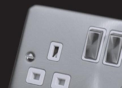
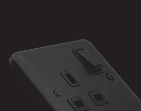
For all your decorative wiring solutions


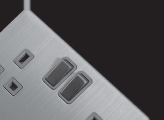

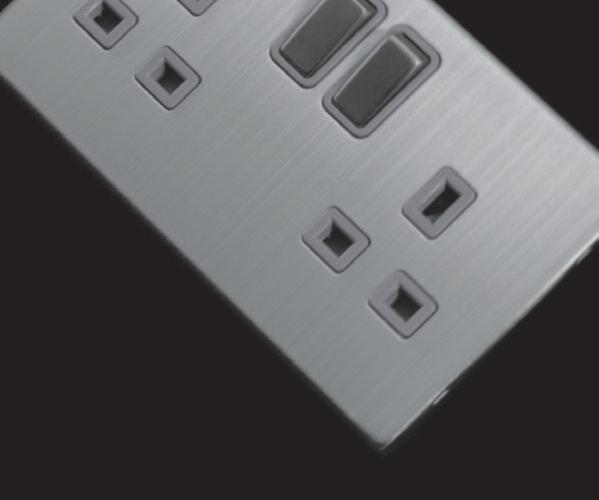





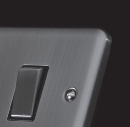
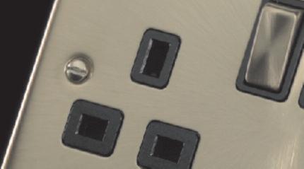
All decorative switch plates are modular as standard.












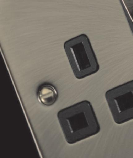


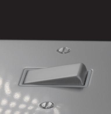










o un ont quickl all l easil es.
al or r all F dec your etivdecora The MiniGrid equire. ou r y plate o cr ou t y ws This allo ear decorativ ll l dec A ear ® switch any y an virtuall eate tandard. tes ch pla wit furnished pla
t mounted changedex y
This allows you to create virtually any switch plate you require. The MiniGrid® modules are all easily and quickly exchanged or mounted onto unfurnished plates.





The team at NAPIT ‘codebreak’ more of the latest reader submissions
12 Metal consumer units in installations forming part of a TT earthing system: what are the key considerations?
15 Is the use of MCBs dwindling?
16 Addressing some of the common queries around EV charge point installations
19 A look at different installation methods and mechanical protection requirements
22 The importance of providing installations with surge protective devices
25 What do IP ratings mean and why is IP68 important?
What are the operating characteristics of a protective multiple earthing (PME) facility?
‘Dr Zzeus’ Tom Brookes answers more of your fire-related questions
30 The importance of safe isolation and why using the right equipment is an absolute must
32 A look at some of the essentials of client handover documentation
34 How to deal with problems with USB socket-outlets that have been faulty following insulation resistance testing
35 How does the ‘Electrician Plus’ concept work?
36 The team at NAPIT ‘codebreak’ more of the latest reader submissions
38 Guidance on the use of the metallic armouring of a cable as a circuit protective conductor (cpc), main protective bonding conductor or an earthing conductor
40 How to respond to the age-old conundrum of how long LEDs really last
43 A look at Chapter 82 of BS 7671 and embedded renewable sources, either used in conjunction with the existing supply for an installation or as an alternative and independent source of electrical energy forming a prosumer’s low-voltage electrical installation (PEI)
46 The team at NAPIT ‘codebreak’ more of the latest reader submissions
48 Getting a better handle on the Construction Industry Scheme (CIS) and specific rules for how contractors must handle payments made to subcontractors for construction work
50 Examining the practice of burying cables
52 What are the requirements of the amended Approved Document Part F and how can electricians meet them?
70 Can flexible cables be used in fixed installations?
73 Taking a look at protective earthing systems and unravelling the difference between PME and PNB
74 Which sequence of testing would be appropriate for use when carrying out a periodic inspection?
76 The team at NAPIT ‘codebreak’ more of the latest reader submissions
79 RCDs for heat pump installations: what are the 18th Edition recommendations?
82 The considerations when selecting a suitable wiring system for an electrical installation
84 How to establish voltage drop limits within an electrical installation
54 The team at NAPIT ‘codebreak’ more of the latest reader submissions
57 A look at the types of SPD recognised by BS 7671 and their location within an installation
61 Smoke alarm installations – what is the hidden requirement in BS 7671?
62 ‘Dr Zzeus’ Tom Brookes answers more of your fire-related questions
63 What are the key features that set single-phase and three-phase power supplies apart?
64 A guide to navigating electrical reflections in circuits
67 Throwing some light on the battle to use self-generated green energy
86 The issues that will influence the decision as to whether or not fused leads need to be employed when using electrical test instruments
88 How do product circularity ratings work?
90 ‘Dr Zzeus’ Tom Brookes answers more of your fire-related questions
93 Exploring site preparation and resistance to both contaminants and moisture
94 How ventilation system design can be made simple for electricians who are keen to install MVHR but aren’t sure how to design and specify
96 The team at NAPIT ‘codebreak’ more of the latest reader submissions
98 Power quality and energy efficiency – what should you be aware of ?
As a result of the ongoing cost of living crisis, many electricians are finding themselves working longer hours and extra shifts. In such testing times, any product that can deliver even marginal time savings is welcome. Mike Cullom, Northern Europe Sales Manager of IDEAL Electrical, discusses the benefits of innovative lever and push-in wire connectors for faster, easier and safer wire terminations.
Are tradespeople working too hard?
It’s fair to say that tradespeople are working hard in the UK. According to research1, the average
tradesperson works between 41 and 50 hours per week, with a fifth working more than 50 hours per week. This is compared to the UK average of 36.4 hours worked by full-time workers per week2.
What’s more, the ongoing cost of living crisis is leaving tradespeople with no choice but to work longer hours and take on extra shifts in an effort to increase their level of income. A recent survey found the number one cause of concern for tradespeople is the cost of living crisis, with almost two in five (39%) saying it’s a major cause of stress, and the same number (39%) admitting to working extra shifts as a result3.
With tradespeople run off their feet, every little helps when it comes to completing jobs in a timely manner without compromising on
quality. This is exactly where lever and pushin wire connectors come in handy, as even small-time savings on a single task like wire terminations can add up to substantial time savings over the length of an installation.
Simply strip, push and connect
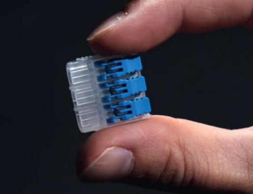
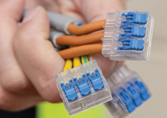
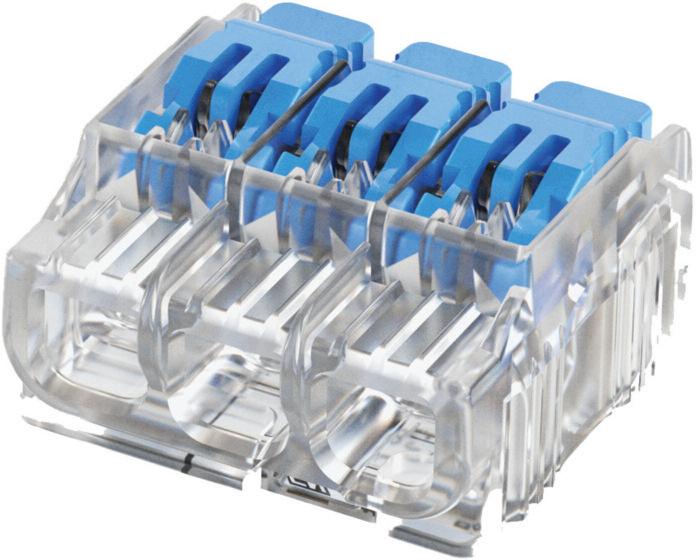
Suitable for joining solid, stranded or flexible conductors, lever and push-in connectors deliver faster, easier and safer wire terminations, and offer a more cost-effective alternative to terminal blocks.
Secure cables in place in mere seconds using a simple strip, push, connect action – no screwdriver or crimping required.
Lever wire connectors:
• Re-useable | 2, 3 and 5 port models
• Allow the use of multiple wires of different sizes and types within the same lever connector.
• Solid and rigid stranded: 0.2mm2 -4mm2
• Flexible: 0.14mm2-4.0mm2
Push-in and in-line connectors:
• Available in 2-8-port models
• 0.5mm2 – 6.0mm2 depending on use of solid or stranded wire
Practical design features
• A clear window at the bottom of the connector to allow easy inspection
• Check port for testing
• Stripping length indication
• Simply push in when using on solid and rigid stranded wires
• 32A or 41A depending on connector
The right connector for every termination
• CE, UKCA and fully compliant with the 18th Edition Wiring Regulations.
As the UK’s cost of living crisis continues to impact the construction and trades industry, the workforce will remain stretched, so it’s a no-brainer to select user-friendly products that speed up installations and make electricians’ lives easier.
Designed to make wire terminations faster and simpler, lever and push-in wire connectors prevent errors and ensure consistency, allowing wire terminations to be carried out more quickly and with less risk of snagging –perfect for when time is of the essence.
idealind.com | idealindustries.com
[1] https://screwfixmedia.com/uk-tradesmen-working-harderthan-ever/
[2] https://www.statista.com/statistics/280763/average-workinghours-uk/#:~:text=Average%20weekly%20hours%20of%20 work,in%20the%20UK%201992%2D2023&text=As%20of%20 July%202023%2C%20the,United%20Kingdom%20was%20 36.4%20hours.
[3] https://www.ironmongerydirect.co.uk/research/mentalhealth-in-the-trades





























W O R K T H R O U G H E A C H S E C T I O N A N D E A R N 6
C P D C R E D I T s ( o r 6 h o u r s o f l e a r n i n g )
T O WA R D S YO U R P R O F E S S I O N A L R E C O R D !
continuing professional development (CPD) can be broadly defined as any type of learning you undertake which increases your knowledge, understanding and experiences of a subject area or role
To help professionals to better document and prove this process, the CPD Book contains content and articles that have been checked, verified and accredited by a third-party specialist organisation
Collectively, the content within this specially designed publication has been deemed worthy of 6 CPD credits, or 6 hours’ worth of CPD, with each individual section providing 1 credit, or 1 hours’ worth of CPD.
Once this content has been consumed, readers will have the

opportunity to scan a QR code which will provide a bespoke, downloadable certificate that can be used as part of a professional’s ongoing CPD record
DO NOT SCAN THE QR CODE UNLESS YOU HAVE READ ALL OF THE CONTENT WITHIN EACH SECTION!
A large element of CPD involves self-certification and relies on professionals being honest about what they have actually read, consumed and digested A QR code has been placed with the final article in each of the six learning sections within this publication and ONLY once you have read ALL of the articles within each section, should you then scan the code to receive your bespoke certificate
By skipping any of these steps, you’re not just cheating the system, but yourself and your fellow professionals at the same time!
NEW USERS – ACCESS YOUR BESPOKE CPD CERTIFICATE IN FIVE STEPS
1. Read ALL of the content and articles included within the six sections
2. Find the QR code with the last article in each section and scan
3 Enter your email address
4. Fill out your details on the contact form
5. Download your certificate for use as part of your annual CPD record
PREVIOUS USERS – ACCESS YOUR CPD CERTIFICATE IN FOUR STEPS
1. Read ALL of the content and articles included within the six sections
2. Find the QR code with the last article in each section and scan
3. Enter your name and email address.
4. Download your certificate for use as part of your annual CPD record
All certificates are valid for one year from the issue date If you’re having any issues with downloading your certificate or using the system, please email us at: pe@hamerville.co.uk





You can never assume that an older installation was installed, commissioned, and tested correctly We often find that older installations can harbour some poor and dangerous practices As we work through the findings, the lack of grommets is no more than perhaps a C3 unless there is mechanical and thermal damage. They ’ve not been there for 40 years, without either, but that ’s not to say ever y installation would be like this Eddy currents only really star t to take effect on equipment subjected to continual high current loads.

In domestic single and polyphase installations, up to 100 A, it ’s ver y unlikely there will be a problem We generally see Eddy current overheating and damage on polyphase commercial and industrial installations, dealing with larger loads In this case, the installation is only 60 A, and storage heaters are only energised for a c yclic period so, unless there are signs of thermal damage, no more than a C3
There also appear to be some cable entr y points not being used, which are likely to represent an IP issue. One certainly
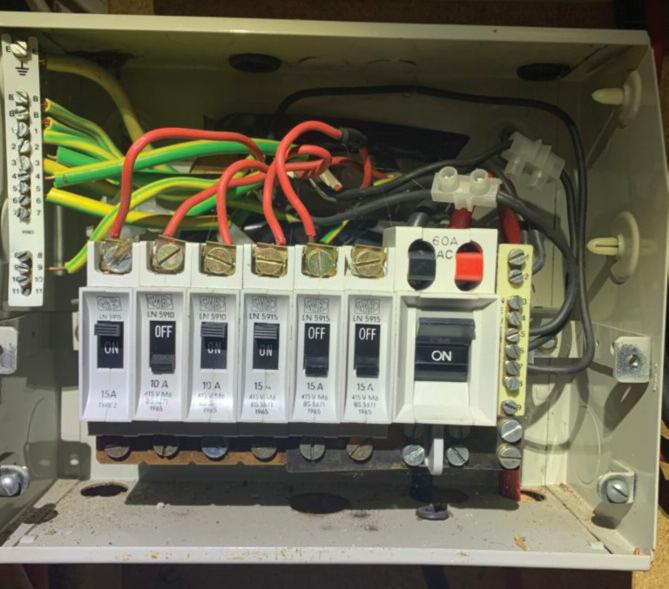

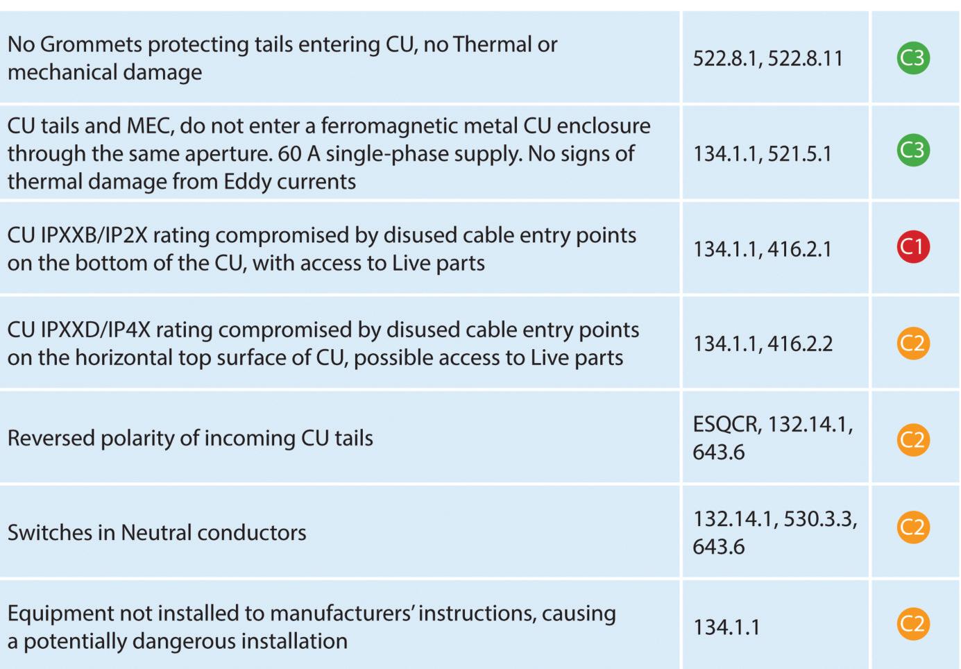
seems to have almost direct access to the bus bar The area of concern here is the reversed polarity, which may well operate normally in a healthy circuit Older storage heaters generally don’t have complex electronic controllers that require correct polarity and, subsequently, don’t have reversed polarity diode protection, which stops the equipment from operating and forces maintenance to be carried out
Also, as the polarity is reversed, we now have switches in neutral conduc tors, which isn’t allowed, and no individual circuit isolation, as the MCBs are only isolating the neutral Not noticing the reversal, a maintenance engineer would think they have isolated a circuit to carr y out some maintenance, only to find that the neutral circuit conduc tors are still live.
The only way to isolate any of the installation storage heaters would be to isolate them at the CU main isolator

GET THE BOOK AND CRACK
Updated for BS 7671:2018+A2:2022, NAPIT ’s EICR Codebreakers publication is purpose -written to aid contractors, inspectors and clients, and now includes updates to align with Amendment 2 of the IE T 18th Edition Wiring Regulations The book is the per fect technical aid for electrical professionals and their customers.


Need help with cracking those all-impor tant EICR codes? Ever y month the technical team at NAPIT will be studying your latest ‘Caught on Camera’ photos and offering advice on the next steps, should you find a similar installation. If you want the team at NAPIT to help crack your codes then send your pic tures through to us at: pe@hamer ville.co.uk




There were so many photos from Kyle’s call- out, so I chose those that I found would give the best impression of the many faults he’d found
Firstly, the left and centre photos show the connections for recessed downlights In both photos, we can clearly see that the cpc has been cropped and not continuous; this means that a cpc has not been taken to ever y point and accessor y in the circuit This alone is an unsatisfactor y finding, but the centre photo shows that the manufacturer had supplied a terminal to connect the cpc, which would have ensured the integrity of the cpc throughout the circuit.
The outer sheath of the twin and ear th cable on both light fittings has been

removed, leaving single insulation exposed and not taken into the enclosure – another unsatisfactor y finding It looks as if the line conductor terminals have been twisted together, leaving only one of the conductors in a termination, relying on the twisting to give mechanical joint stability, so again not satisfactor y

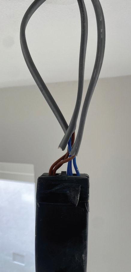
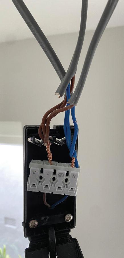
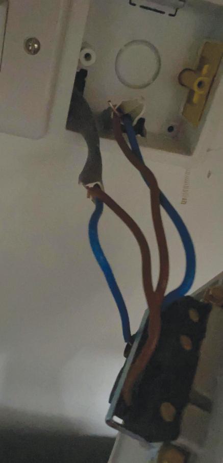
In the third photo, which I’m assuming is a fused connection unit (FCU) (as the photo isn’t too clear), we can again see the cpc is cut and not continuous; therefore, not taken to each accessor y and point in the circuit. With the general lack of elec trical understanding, by removing the cpcs, which are fundamental to safety, it ’s more than possible that the dishwasher has a current present on its housing or casing.
The current present could be innocent leak age current, which is classed as functional and therefore normal, but without a cpc to allow this to have a pathway back to the ME T, anyone in contact with it could become the pathway. I t is most likely that the shocks were perceived shocks. Regardless, perceived shocks can instill a significant amount of fear into those receiving them and highlight that the installation user could receive a fatal electric shock in the event of a fault
A genuinely horrific installation, cobbled together by someone with no understanding, sk ills, or conscience.


The A2:2022 18th Edition Codebreakers publication is priced at £22.00 (members) and £24.00 (non-members). It is available in both hard copy and digital versions * Price is VAT exempt and excludes postage and packaging.





This article from the experts at NICEIC aims to provide guidance for contractors when required to install a consumer unit and/or similar switchgear manufactured from a noncombustible material meeting the requirements of regulation 421.1.201, in a domestic installation forming part of a TT system earthing arrangement.
Where an installation forms part of a TT system earthing arrangement, irrespective of the type of material the consumer unit is manufactured from, regulation 411 5 2 typically requires the installation of one or more RCDs as a protective measure for fault protection
Any RCD providing fault protection shall be erected at the origin of the installation that is to be protected (531.3.5.3.1). In an installation with multiple origins, this requirement shall apply to each origin
Most TT installations are likely to also contain multiple RCDs providing additional protection, or possibly fault protection, either protecting groups of circuits and/or individual circuits. Where this is the case these protective devices shall be selected and erected as to limit the risk from unwanted tripping (531 3 2) Similarly, where multiple devices are installed and there is a need to minimise the inconvenience of unwanted tripping during a fault, the requirements for selectivity will need to be considered (536 4 1 4)
The installation of a metallic consumer unit complying with BS EN 61439-3 is most likely to be the preferred option for
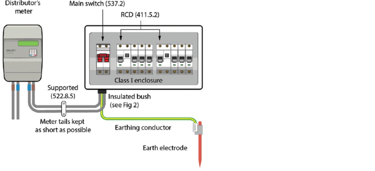
achieving compliance with the non-combustibility requirements of regulation 421 1 201 However, care must be applied to the installation method adopted where a metal (Class I) consumer unit is installed in an installation forming part of a TT system
An earth fault occurring between the line conductor of the meter tails and the metallic enclosure, as shown in Fig 1, will not be detected by the RCD installed in the consumer unit. The metallic casing of the consumer unit and subsequently all other conductive parts connected to the main earthing terminal (MET) of the installation will rise to a potential approaching close to the supply voltage (230 V to Earth), creating a potential shock risk.
Under such circumstances, due to the
high external earth fault loop impedance (Ze) typically associated with a TT system, which can often exceed 100 Ω, the earth fault current is unlikely to reach the level required to operate the service fuse, and even if it does the operating time is unlikely to be within the 1 s disconnection time required by regulation 411 3 2 4
For example, if the maximum earth fault loop impedance is taken as 100 Ω also taking into account the seasonal changes of ground resistance for a single phase supply, and minimum voltage factor (C min) of 0 95, the earth fault current that will flow under such fault conditions can be calculated as follows:
��fc = 230 x 0 95= 2 2 �� 100
Clearly, this level of fault current is insufficient to operate the distributors’ overcurrent protective device and therefore, unless a low value of (Z s) can be assured and maintained while meeting the requirements of regulation 411 5 3 for fault protection, such a fault will remain uninterrupted For this reason it is preferred that fault protection for an installation forming part of a TT system is provided by an appropriately rated RCD (411.5.2).
In addition, the selection of an appropriate RCD for a particular installation shall meet the requirements of regulation 531 3 5 3 2 Such that, the rated residual operating current (��Δ ��) of the chosen RCD shall not exceed the (��Δ ��) corresponding to the maximum value of earth resistance (Ra), including that of the earth electrode and protective conductor connecting all exposed-conductive-parts
In the aforementioned example the maximum earth fault loop impedance is 100 Ω and therefore, the maximum rated residual operating current of the chosen RCD shall not be greater than 500 mA, given in Table 53 1 of BS 7671 and partially reproduced in Table 1
It may not be possible to eliminate all risk associated with protecting meter tails from a fault to earth typically, between the origin and the RCD protective device within the consumer unit However, by adopting longstanding industry practices applied by many electrical contractors, such as those listed below, the risk can be mitigated sufficiently:
● use of thermoplastic or thermosetting insulated and sheathed cables for the meter tails (531 3 5 3 2 201), and ● positioning of the consumer unit in close proximity to the energy meter, reducing the length of the meter tails to a minimum to mitigate the risk of damage,
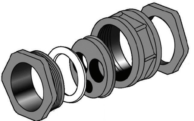
● fitting an insulated cable gland, bush or similar to protect the cables from abrasion as the meter tails enter the metallic consumer unit and/or protective enclosure, as shown in Fig 2.

Additionally, in order to avoid the effects from induced eddy currents in the metallic enclosure and any consequent heating effects, all associated meter tails should enter the consumer unit through the same entry point (one cable entry knock-out hole).
The requirement of regulation 421 1 201 is intended to ensure that any source of ignition, such as arcing caused by a loose termination occurring within the consumer unit and/or switchgear assembly, is prevented from igniting the enclosure while reducing the risk of any fire from spreading externally
It is for this reason that the entry points of all cables, including that of the meter tails, into the metallic consumer unit should not, so far as reasonably practicable, reduce the fire integrity provided by such equipment Cable entries, such as those often used for back entry into the consumer unit must be provided with suitable sealing methods and may include intumescent gaskets, grommets and/or fire sealants to maintain the degree of fire integrity
However, it is generally accepted that the requirements of regulation 416 2 1 and 416 2 2 which are intended to prevent contact with live parts also help to maintain the fire integrity of the consumer unit. A degree of protection of at least IPXXB or IP2X should be maintained for the top surface of the consumer unit and a degree of protection of at least IPXXD
or IP4X maintained for all other surfaces of the enclosure
Where the installation of a consumer unit is to take place on or in a combustible prefabricated wall, additional precautions must be applied to prevent the ignition of surrounding materials. Equipment having a greater degree of protection will be required which must be maintained of at least IP3X (422 4 1) Using appropriate types of equipment conforming to the relevant standards for temperature rise will meet this requirement (422 4 201)
Where the installed equipment, such as an all-insulated construction consumer unit, fails to meet the requirement of regulation 422 4 201 further preventative measures shall be applied to prevent the spread of fire. This may include the use of a secondary enclosure manufactured from a non-combustible material of suitable thickness, for the containment of the consumer unit (422 4 202)
There is a greater risk associated with the installation of a metallic consumer unit in an installation forming part of a TT system earthing arrangement It is for this reason that consideration must always be given to the location of the consumer unit and length of meter tails in relation to the energy meter.
Appropriate installation methods and practices that have been applied by electrical contractors for many years continue to minimise the risk of damage to the meter tails and subsequent earth faults It must be recognised the need to maintain the degree of ingress protection and the fire integrity of the consumer unit in relation to the type of installation method


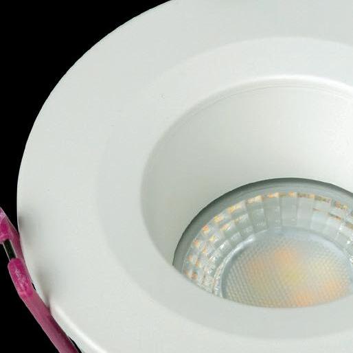
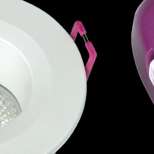
Recessed Light Source for Enhanced Visual Comfort & Reduced Eyestrain





Front-Access
CCT4 Switch

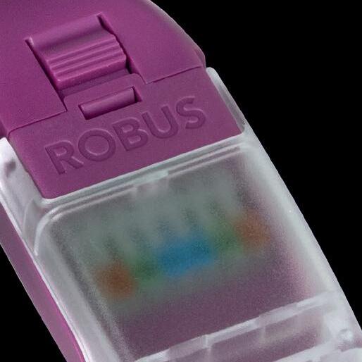
Colour-Coded Lever Terminals

Dual-Wattage Base Switch

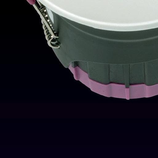
Transparent Connector Cover Loop In, Loop Out


The fire rated downlight you asked for, now with anti-glare.
Available in your local wholesalers
e y Availabl Av esal al whol oc our l e ser
Multiple Trims to Adapt On-The-Go: Black, White, Chrome. Matching Reflector Insert for Soft Illumination
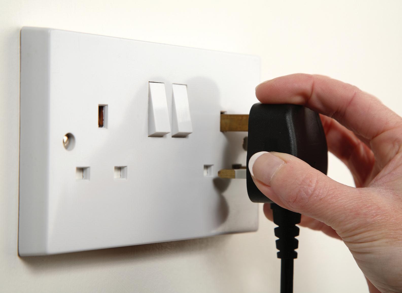
Keith Willcock, Product Manager for Siemens Alpha Circuit Protection Products, reviews the implications for designers and installers of electrical installations from the latest requirements for additional protection for socket outlets in BS 7671, including Amendment 2.
Regulation 411 3 3
Within Chapter 41 (protection against electric shock) Regulation 411 3 3 now tells us:
‘ in AC systems additional protection, by use of a 30mA residual current device, must be provided for socket outlets (not rated higher than 32 A) in locations where those socket outlets are likley to be used by persons of capabilty BA1, BA2 & BA3 There are no exceptions to this requirement ’ Previously this regulation did not overtly consider user capability The regulation concerned itself with the equipment type i e socket outlets Now the person using the socket outlets is the principal consideration for designers and installers
What are BA1, BA2 & BA3?
The terms BA1, BA2 & BA3 are explained in BS 7671 Appendix 5 of the Wiring Regulations, which includes a list of external influences, and, in table B, under the sub heading of ‘Utilization’ BA, refers to the capability of persons. BA1 is described as an ordinary person (a person who is neither a skilled person nor an instructed person), BA2 as children, and BA3 as disabled persons
Which locations are included?
Regulation 411.3.3 does not give a list of typical locations, so designers and
installers have to determine for themselves which locations include socket outlets that are liable to be used by ordinary persons, children or disabled persons
Typical obvious locations will include schools, universities, offices, factories, hospitals, nurseries, care homes, hotels, and indoor/outdoor locations Actually, its hard to exclude any locations, the requirement really means all workplaces, all leisure facilities, and all living accommodation. No exceptions permitted.
What is a socket outlet?
People probably imagine a common BS 1363, 13 A, three pin socket outlet when they read Regulation 411 3 3, but the regulation isn’t limited to 13 A sockets – it includes all types of socket outlets up to a maximum rating of 32 A
The regulations state that a socket outlet is a device, provided with contacts, which is intended to be installed with the fixed wiring, and intended to receive a plug Taking account of all the types of premises with the relevant locations covered by this regulation there will be a wide variety of socket outlets that must have additional protection by a 30mA residual current device, including 2, 5, 13, 15, 16, 20 and 32 A round pin, square pin, fused or unfused indoor or outdoor sockets.
The simplest compliant solution is to use an individual Type A 30mA RCBO on each circuit that supplies power to any socket outlet This will meet the requirement for additional protection, avoid unwanted tripping, and maintain power continuity on healthy circuits
Type A RCBOs are suitable for circuits with equipment incorporating electronic components that may produce DC currents; such equipment is commonplace in modern installations. Type A RCBOs are designed to trip on alternating sinusoidal residual current and on residual pulsating direct current MCBs won’t meet the requirements of BS 7671 for additional protection and shouldn’t be utilised for the circuits that supply socket outlets which will be used by ordinary persons, children or disabled persons
Footnote:
Designers should not group several socket circuits on a single 30mA residual current device as this can actually cause unwanted/nuisance power outages to healthy circuits that share an RCD with a faulty circuit, and is very unlikely to comply with the wider requirements of BS 7671: Chapters 13 & 31, Regulations 531 3 2 etc

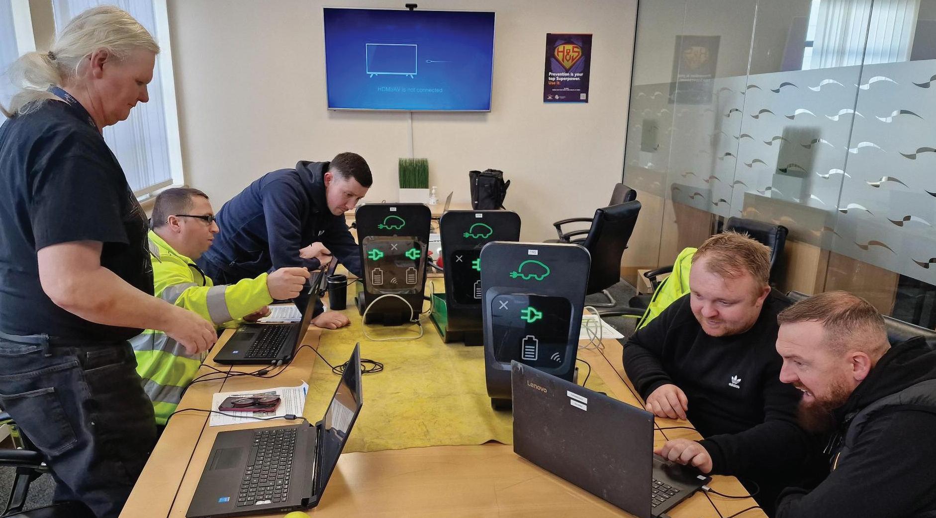
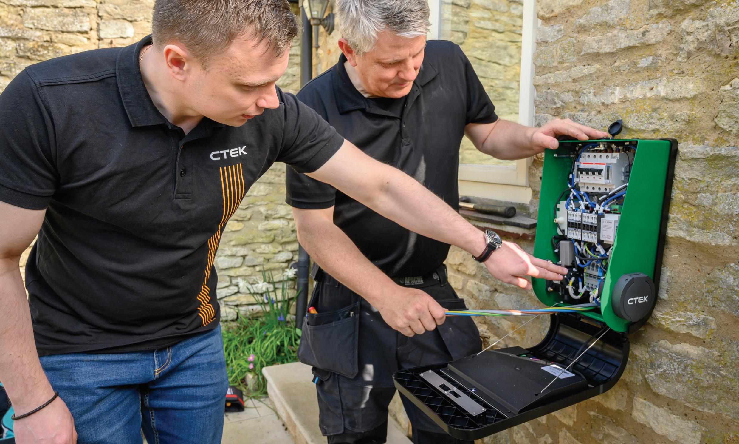
Installers at our UK training sessions will ask a lot of questions when they’re learning how to best install EV charge points But, there are certain topics that will crop up time and again at training events up and down the country
In my experience, installers are keen to find out all about EV charging, how the charging units work and the steps to effective installations They’re an inquisitive lot and ask some very good questions at each session
Last month I covered questions relating to EV charge point RCD protection, IK impact ratings and AC & DC chargers This month I’ll broach two more questions:
QWhich type of load management is needed?
Introduction of any EVSE equipment to a property will inevitably add additional strain onto the supply network and the local installation itself It is important to understand what the maximum demand of the property is prior to installation of charging points It is also important to remember that diversity cannot be applied to EVSE since it will operate at
In this follow up to his first article, Viktors Nikolajevs, CTEK’s Skillbase Manager in the UK, answers more of the key questions that installers are commonly raising around EV charge point installations.
the rated level continuously, unless limited through configuration or instructed otherwise by the vehicle
BS 7671:2018+A2:2022 Section 722 311 201 states that load curtailment, including reduction or disconnection, either automatically or manually, can be taken into consideration when determining the maximum demand of the installation In many situations manual load reduction (through configuration) can impede the user experience when charging vehicles, so automatic approaches through load management equipment or software would be more appropriate.
There are two variations of load management solutions available – static and dynamic Dynamic load management typically includes installation of additional meters and/or current transformers to the incoming supply to measure the overall power consumption of the property The measured values would then be assessed by the EVSE or the load management controller, allowing the EVSE to use the remainder of the supply to charge the EV
Furthermore, DNOs may require dynamic load management to be installed if the Maximum Demand thresholds, explained in Energy Network Association (ENA) Electric Vehicle Charge Point and Heat Pump Connections Process, are reached or if local transformers have limited capacity
Static load management can be used in installations where the actual power consumption of the property is known and is relatively stable The power consumption of the property does not need to be measured continuously, so there is no need for additional meters or CTs, and there is a dedicated amount of power capacity dedicated only for vehicle charging. The load management is then
carried out against this dedicated power capacity. Such solutions can be well suited for small office buildings with a low number of charging points
Installers and designers have to consider whether online or offline load management is more appropriate When using online (cloud-based) solutions, consider how the charging points would behave in case of internet access loss This behaviour varies from manufacturer to manufacturer, and in some cases can either send the chargers to minimum output mode, maximum output mode or disable them completely.
Offline solutions operate locally. Should connection to the internet be lost, the load management will continue to function as pre-programmed by the installer
QWhat is the OCPP and why do I need to know about it?
Open Charge Point Protocol (OCPP) is an open-source communication protocol used to make EV networks open and accessible It can be thought of as a common language, which allows different hardware manufacturers and software developers to produce cross-compatible solutions, even if they have never worked together
OCPP-compliant hardware providers allow the customers to decide how they want to operate their charging points, which software they use or which EV charge point tracking Apps can interact with the stations Additionally, should a manufacturer of OCPP-compliant hardware or the back-end provider go out of business, the owner will have an easy way of switching the back-end, rather than completely losing access to their charging points
In simple terms, when manufacturers implement OCPP support, the EV charge point owner/operator can decide what software platform they want to use to manage their charging network and set up methods of payments The EV charge point operator can then manage charging stations from different manufacturers in the same software
Another aspect of often overlooked benefits of OCPP is hardware longevity If the manufacturer of EV charging stations without OCPP support goes out of business or stops supporting those stations on their platform, then the stations would lose all of their smart functionality or become completely disabled Having OCPP allows switching the back-end software to prolong the
longevity of hardware should such unforeseen circumstances occur.
Currently, there are three versions of OCPP available – 1 5, 1 6 and 2 0 1 The most commonly used version now is 1 6 Both the charging point and the back-end solution should be able to use the same version of OCPP for successful connection.
The appetite for EV installation training is growing all the time as more installers want to expand their knowledge of what is a huge growth market.
A City & Guilds survey of installers found 45% of employers only recruit electricians who are already qualified or competent to install EV chargers So, here at CTEK we’re committed to providing our Skillbase training to many more installers
Installers are invited to free online CTEK training events to learn more about installing EV charging infrastructure The sessions will run at 9am and 1pm

The technical experts at NAPIT look at different installation methods and the mechanical protection requirements for each.
Installation or wiring methods?
Whenever we speak to contractors or they ask our advice on an installation or wiring type, there is often some confusion over the different installation methods and how they can be used.
Let’s be clear, wiring methods are different ways of saying installation methods, so they are generally taken as being the same principle
What’s a wiring system?
These differ slightly from installation methods and refer to a cable or system containing both basic and mechanical protection when installed and commissioned correctly
PVC/PVC flat twin and earth cables are classed as a wiring system as they possess all of these properties and also include a cpc, as do SWA, MICC, soft skin
fire cables (FP200 and similar) and many other similar cable types
The systems we use to support these cables are referred to as containment because they contain the cable wiring system A containment system or method

is not a wiring system, and in most cases, it can be used for, or with, many different wiring systems
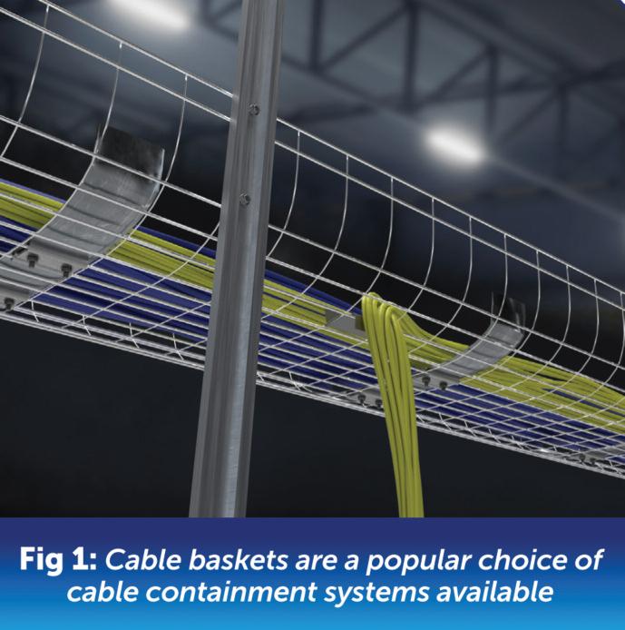
One such example of a containment system is the cable basket, as shown in Fig 1, where the open metal frame design offers less surface area so increases air circulation and prevents both heat and dust build-up
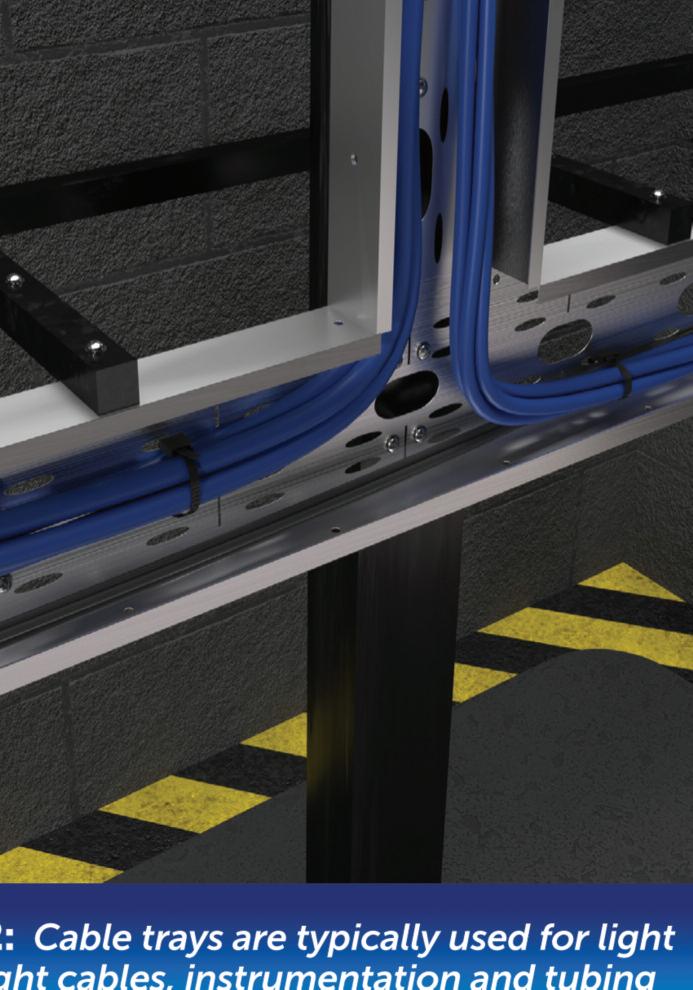
Another cable containment system is the cable tray, as displayed in Fig 2, which are commonly used to support a multitude of light-weight cables. In the same way, we may choose to use cable clips or cleats These can be used for many differing wiring systems; the clips or cleats themselves vary by design, but the principle behind their use is basically the same
For heavy duty and high volume cables, cable ladders are typically used as a containment system, as shown in Fig 3

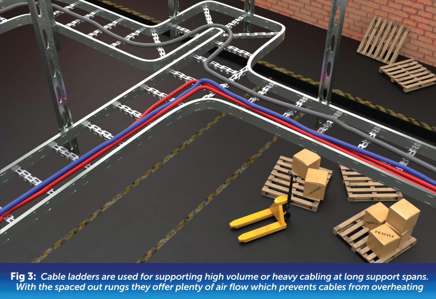
When we use singles, 6491X and similar, these are only half of the system
As 6491X cable only possesses basic insulation and no mechanical protection, we have to install them inside suitable mechanical protection. We can’t call 6491X cable a system, unless we also refer to its mechanical protection part at the same time
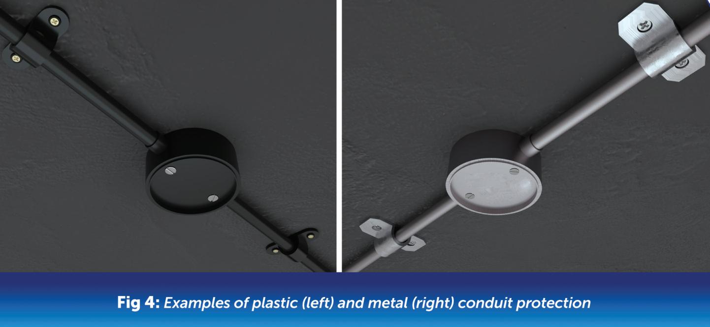
There are two basic principles for mechanical protection of 6491X single cables, which are conduit and trunking These again are split into two types of material construction, leading to four distinct types in total
Fig 4 shows the two material types for conduit protection, metal and plastic
For 6491X to be called a system, it needs to be referenced with one of these four mechanical protection parts. These two mechanical protection parts of a system, conduit or trunking, although they serve the same purpose, have very different properties and skill sets needed to install them
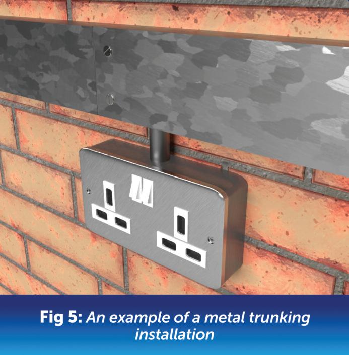
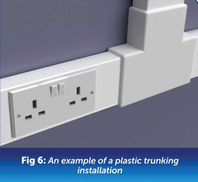
Fig 5 and Fig 6 indicate the two material types of trunking, metal and plastic Indeed, the different materials used to construct each of them also have very different installation techniques and skill set requirements
We generally wouldn’t use a separate containment for 6491X/conduit systems, as the system itself is the containment. A conduit system, whether metallic or plastic, will use saddles to secure them, but these are considered to be integral to the wiring system and not optional We wouldn’t lay conduit or trunking onto a cable tray or basket, for example, as this is not a proper use of either piece of equipment.
Flexible metallic conduit is often utilised for connections to equipment, although there has been an increase in its use for connecting solid metallic conduit between expansion joints within buildings and similar
One thing to remember is that flexible metallic conduits are unsuitable for use as a cpc; therefore, any links between fixed metallic conduits would require earthing links to ensure the earth continuity of the containment system.
What about the cpc?
With metallic conduit and trunking, the structure itself takes on the role of the cpc, so only the line and neutral of the circuit are carried internally, with a connection made at the accessory to either the conduit or the trunking
Plastic conduit and trunking are obviously non-conductive, so the cpc for each circuit must be taken inside with the line and neutral conductors to each accessory served
one do I use?
A designer can use whichever they choose to, but will generally be driven by the following:
● Client needs or requirements
● Usage
● External influences
● Durability
● Accessibility for maintenance, repairs or alterations
Whichever method is used, the installer must possess the correct skills needed Complex wiring systems need high levels of competence and experience to ensure compliance with BS 7671.
Both plastic conduit and trunking arguably require less complex equipment and training to construct; however, they are not easy to install correctly Metal conduits generally require specialist equipment to install, and metallic conduits will likely involve powered cutters or tooling.
When dealing with containment, the same applies, although generally speaking, power tools will need to be used to install most cable tray and ladder products
Can you mix and match?
Mixed systems are often seen and indeed necessary, for example, when going from a trunking system to a conduit system to disseminate final circuits for point of use, etc
We also see cable systems inside trunking to reduce the need for
unnecessary containment, where the circuits wired in a cable system are limited. It’s usual to see the odd SWA, MICC or other such cables in trunking alongside 6491X singles, especially where modifications and alterations to an installation have been made
Things can get trickier with conduits, as the friction from pulling a sheathed cable system through them can damage them and any other 6491X singles in the same conduit
In both cases, the designer needs to take into account any thermal constraints, as a wiring system may have its current capacity impaired by the enclosed effects of being encased in a conduit or trunking Likewise, the thermal constraints of the 6491X conductors may be affected where a sheathed wiring system is introduced to
the same conduit or trunking
We can’t mix and match 6491X or similar singles by placing them on either a cable tray or ladder, as they would not have mechanical protection So, from a mix-and-match perspective, wiring systems can use trunking and conduit as a containment method if thermal constraints allow, but singles must be in either conduit or trunking.
Often seen as a domestic-only wiring system, PVC/PVC flat twin and earth, is actually far from it Twin and earth and similar variations are wiring systems in their own right, and can be used in commercial and industrial installations, where the designer sees fit
The only problem you will find is that
they are less flexible, given their solid conductors, below 4 mm2. Other than that, they can be used anywhere a similarly specified cable wiring system can be used, providing they meet the requirements for low smoke and fumes
We have several options for the type of installation method we use; each has its merits, drawbacks and varying levels of difficulty of installation This is beneficial as it gives the designer options to choose the best possible solution


Hager’s Technical Training Manager, Paul Chaffers, discusses the importance of providing installations with surge protective devices (SPDs) and looks at requirements and considerations of BS 7671:2018+A2:2022.
in our everyday life, we’re surrounded by electrical equipment which may contain sensitive electronic components Such products are vulnerable to transient overvoltages and can have their lifespan significantly reduced through degradation and damage. Understanding overvoltage protection can be very complex, but from an electrician’s point of view, the Wiring Regulations are now much simpler than previous editions that required complex thunderstorm risk assessments
Voltage disturbances in the form of overvoltage can originate from outside of an installation or from within the installation itself In fact, about 35% of all transients come from outside the facility with the remaining 65% generated inside our homes and facilities – see Table 1 (pictured, right) for examples of where such transients may originate from
Understanding how to use BS 7671 correctly is the key to success Unfortunately, too often installers look at an isolated “Section” or “Part” of the Regs, without considering the general requirements that must always be applied An example of this would be only looking at Section 443 (Protection against transient overvoltages of atmospheric origin or due to switching) and not considering the Fundamental Principles.
BS 7671 Chapter 13 deals with Fundamental Principles, with Regulation 131 1 providing a number of conditions in electrical installations that may present a risk of injury Indent (iv) of Regulation 131 1 includes voltage disturbances (undervoltage and overvoltage) meaning
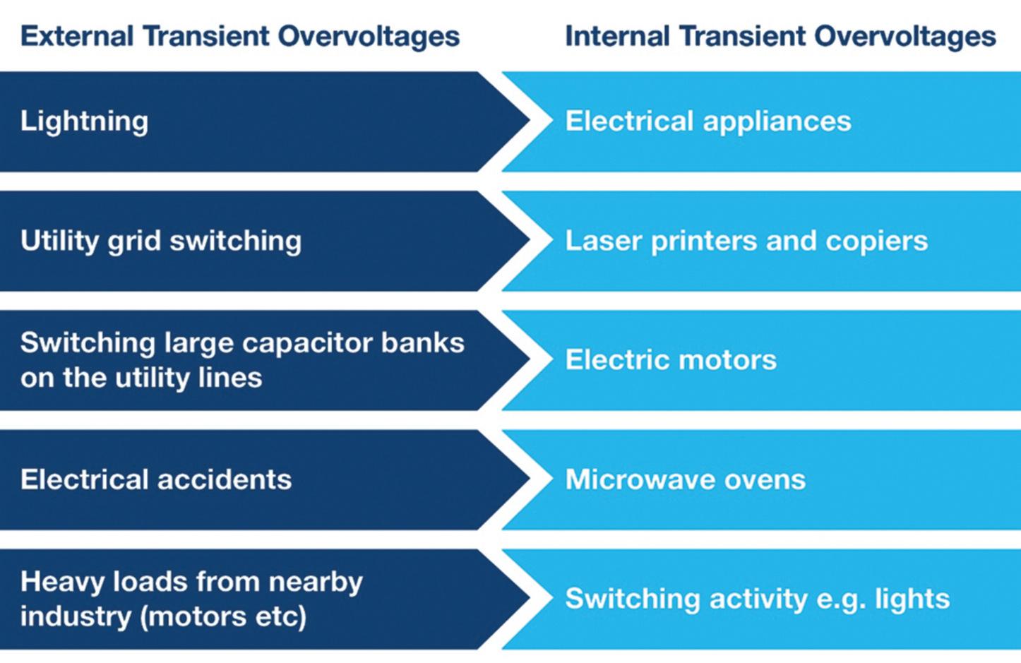
that where there is a threat of this occurring, protection is required
Furthermore, Regulation 131.6.2 requires persons and livestock shall be protected against injury, and property shall be protected against damage as a consequence of overvoltages
Part 2 of BS 7671 does provide some clarity for understanding the consequences of direct lightning strikes or indirect lightning strokes, as follows:
Direct lightning strike
Lightning strike impacting a component of the network directly.
NOTE 1: Examples of components of the network are: conductor, tower, substation equipment, etc
NOTE 2: Consequences of a direct lightning strike include the thermal, magnetic and
“Voltage disturbances in the form of overvoltage can originate from outside of an installation itself.”
mechanical effects of the discharge current as well as the surges resulting from its voltage drop along the discharge path
Indirect lightning stroke
Lightning strike that does not impact directly any part of the network but that induces an overvoltage in that network.
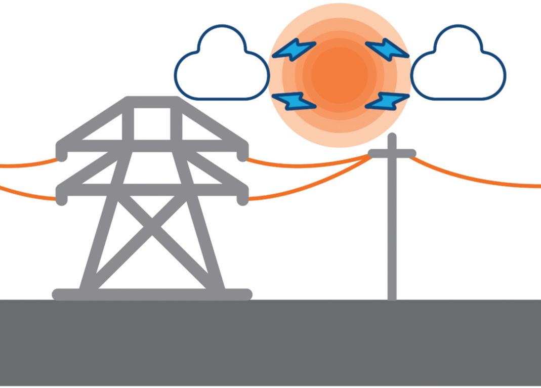
NOTE: Consequences of an indirect lightning stroke for electrical installations are the associated overvoltages and the energy content of the incoming surge wave Should lightning strike near power lines (indirect stroke), then the magnetic effect of this lightning current rushing to earth
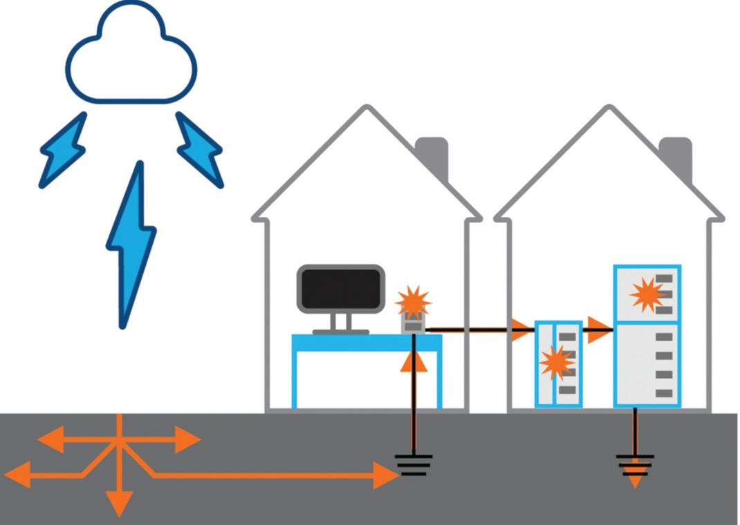
will induce a voltage on anything conductive (i e power lines passing through this magnetic field) This is known as inductive coupling – see Fig 1
The power cable could even be underground and if the lightning struck somewhere nearby a massive amount of current will be injected into the ground
As the current flows away, a voltage will be induced; this is known as resistive coupling which is the most common cause of indirect atmospheric transient overvoltages
Such transients occur when a lightning strike raises the electrical potential of one or more of a group of electrically interconnected buildings, as illustrated in Fig 2 Examples of vulnerable interconnections include:
● DNO feed from substation to building
● Submains from building to building
● Supplies to external equipment, lampposts, CCTV, EV charge points etc
● Telephone lines
● Data and communication lines
Overvoltage control
Chapter 443 deals with protection against transient overvoltages of atmospheric origin, or overvoltages which are associated with switching activity within an installation, with Regulation 443.4.1 prescribing:
‘Protection against transient overvoltages shall be provided where the consequence caused by overvoltage could:
● Result in serious injury to, or loss of human life, or
● Result in significant financial or data loss
For all other cases, the default position is to provide protection against transient overvoltages unless the owner of the installation states that it is not required due to any loss or damage being tolerable If the client makes this decision, obviously they will be accepting the risk of equipment damage and any consequential loss
The modern home will have an abundance of electronic equipment which could easily be damaged by overvoltage and for this reason SPDs are often included
It should be noted that where the word “shall” is used in BS 7671, the implication of that Regulation is a requirement and normative
Overvoltages associated with lightning are severe, but overvoltages associated with switching are more common and in fact can be longer in duration and contain more energy than transient overvoltages of atmospheric origin
This means that where inductive or capacitive equipment is installed, it is likely that switching overvoltages or disturbances will occur. Regulation 443 4 2 deals with transient overvoltages caused by equipment and advises that protection against overvoltages shall be considered
Examples of inductive or capacitive equipment likely to cause such disturbances within an installation are:
● Motors
● Transformers
● Capacitor banks
● Storage units
● High current loads
The examples provided in Regulation 443 4 2 are associated with commercial installations, however consideration for protection against switching overvoltages is equally as important for residential applications. High inrush currents associated with the switching of LED light fittings is one example of equipment likely to cause voltage disturbance and a good example of the type of sensitive equipment that requires protection
Regulation 443 1 1 explains that switching overvoltages typically have a lower amplitude than transient overvoltages of atmospheric origin This means that where protection is provided for transient overvoltages of atmospheric origin, it will usually protect against switching overvoltages
Where the threat of lightning is low and no protection is provided, protection will still be required for switching activity For this reason, Hager recommends consumer units are fitted with Type 2 SPDs and can supply consumer units with SPD kits factory fitted, saving contractors time otherwise spent installing the individual parts

DOWNLOAD HAGER’S 18TH
EDITION AMENDMENT 2
BITESIZE GUIDE AT:

Chris Hudson, MD of Hudson Lighting, explains more about the importance of IP68 ratings for recessed outdoor lights and gives a general overview of IP ratings and what they mean.
Ingress Protection (IP) ratings are crucial for understanding the environmental resilience of electrical fixtures, especially outdoor lighting An IP rating consists of two digits, indicating the device's resistance to solids and liquids, respectively However, the specific requirements for outdoor recessed lights demand a higher level of protection, with IP68 being the ideal choice Before we delve into why IP68 is vital for recessed lights, let's overview the IP rating system:
● IP00: Offers no protection against contact with any object or ingress of water.
● IP10 – IP40: Offers protection against objects larger than 50 mm (IP10) down to 1 mm (IP40), but no water resistance
● IP50 – IP60: Fully dust-protected, but offers no protection against water ingress
● IPX1 – IPX4: No protection against dust ingress but offers water protection against vertically falling drops (IPX1) up to splashing water from any direction (IPX4)
● IPX5 – IPX6: Still no dust protection, but can withstand water jets (IPX5) or powerful water jets (IPX6)
● IP5X – IP6X: Fully dust-protected (IP5X) to dust-tight (IP6X) but offers no water protection
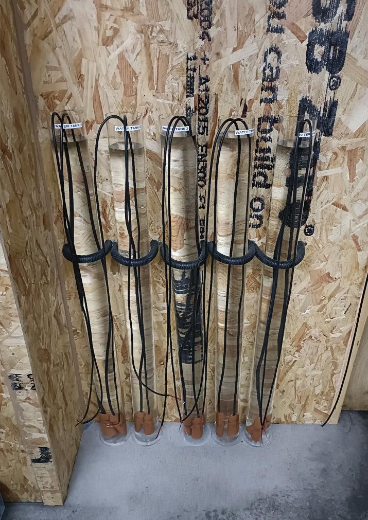
● IP65 – IP66: Dust-tight and can resist water jets (IP65) or powerful water jets (IP66).
● IP67: Dust-tight and can withstand temporary immersion in water up to 1 metre
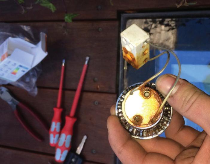
● IP68: Dust-tight and can endure continuous immersion in water beyond 1 metre Recessed outdoor lights often face more strenuous conditions, potentially sitting in/under water for extended periods – conditions that would severely challenge IP66 or IP67 rated lights
While IP66 and IP67 lights offer protection against powerful water jets and temporary immersion in water, neither is suitable for prolonged water exposure, typical for recessed lights That's where IP68 comes into play
IP68 rated lights are dust-tight and can withstand continuous immersion in water beyond 1 metre. This makes them an ideal
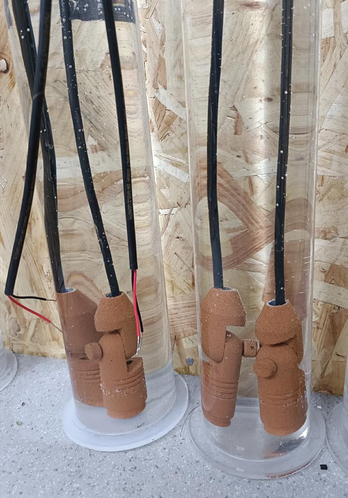
choice for recessed outdoor lights It ensures your lighting investment withstands the elements and continues to perform optimally, even under challenging conditions While the difference between IP67 and IP68 may seem minor, it's this small distinction that significantly impacts the lifespan and performance of your garden lights.

SECTION 1 ENDS! SCAN THE QR CODE TO CLAIM YOUR CPD CREDIT FOR


The aim of this article from the experts at NICEIC is to explain the operating characteristics of the protective multiple earthing (PME) earthing facility, a type of TN-C-S system, which is commonly provided for both new and existing electrical installations.
In a PME arrangement the supply neutral conductor functions as both protective and neutral conductors and is connected to multiple earthing points along the route of the supply network, as shown in Fig 1
The supply neutral conductor of a PME earthing facility – often referred to as a PEN (protective earth and neutral) or CNE (combined neutral and earth) conductor –is terminated at the distributor’s switchgear (cut-out) where connection of the earthing conductor to the supply neutral is achieved by means of an internal link provided by the distributor
Regulation 543.4.1 states that within an installation PEN conductors shall not be used, except where one of the conditions described in regulation 543 4 2 is met Therefore, separate neutral and earth conductors must be used within the consumer’s installation
Because the supply neutral is connected to earth in a PME system, the fault return path for both line to earth and line to neutral faults is via the combined
“ ... a PME system is not permitted in hazardous locations such as petrol stations where there is high risk of ignition of explosion.”
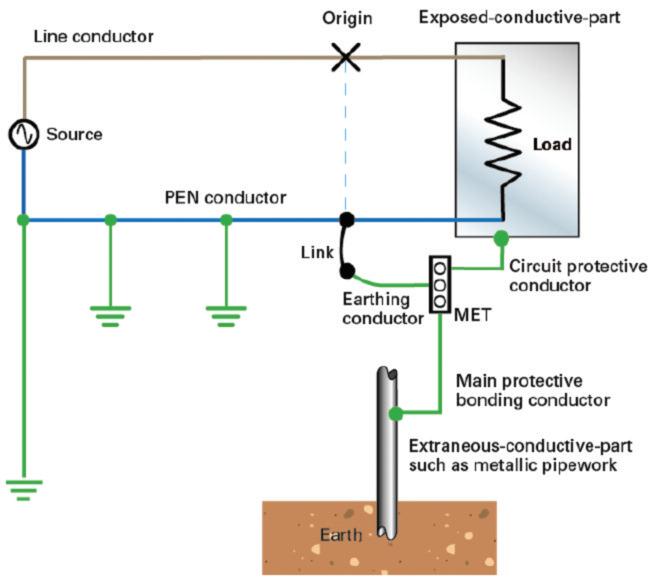
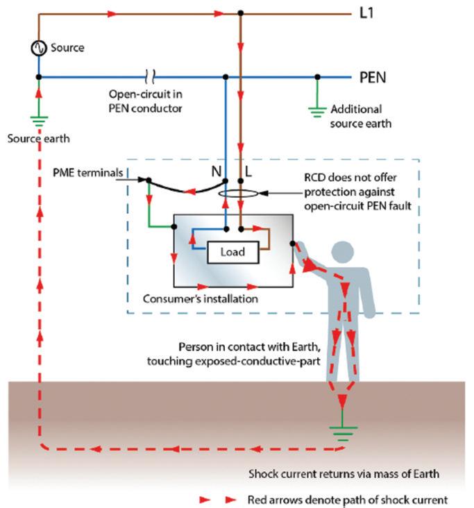
Fig 2. Open-circuit in the PEN conductor
conductor Using the combined conductor in this way has the advantage of providing the return path with a low impedance, therefore allowing for rapid disconnection of circuit protective devices under fault conditions
The Distribution Network Operator (DNO) will typically specify a significantly lower maximum external fault loop impedance Ze for a TN-C-S system than for a TN-S system of the same current rating
The returning current in a PME system has two possible paths, through the combined conductor and the general mass of Earth Depending on their relative impedances, some current, often referred to as neutral current diversion (NCD) or circulating neutral current, may return via the general mass of Earth For this reason, a PME system is not permitted in hazardous locations such as petrol stations where there is high risk of ignition or explosion. Other issues relating to a PME system include the following:
A small voltage difference may exist between the PME earthing terminal at the origin of the installation and the general mass of Earth under normal conditions and is dependent on the distribution network configuration and loading conditions
This small voltage above Earth potential could, under certain circumstances result in a ‘perceived shock’ for a person simultaneously in contact with an exposed-conductive-part
or extraneous-conductive-part and ‘Earth potential’. Such effects may occur in locations where a reduction in body resistance is likely due to the presence of water such as a shower area within a sports facility
An open-circuit in the PEN conductor within the network, as shown in Fig 2, can cause the combined neutral/earth terminal at the consumer’s cut-out to rise above Earth potential, due to its carrying of load currents from installations downstream of the open-circuit. Consequently, the protective conductors at the main earthing terminal and subsequently all other protective conductors within the installation are also likely to rise in potential
Similarly, any metallic parts, such as gas and water pipework connected within the consumers’ installation are also likely to rise above Earth potential, creating a shock risk to any person in simultaneous contact with such parts and the general mass of Earth
There is also the potential risk of fire and thermal damage to cables, in particular, flat twin and earth cables where the non-insulated protective conductor typically has a smaller cross-sectional area (csa) than the associated live conductors
For this reason, it may be inappropriate to use a PME system arrangement in some premises and prohibited in certain other installations For example, regulation 9(4) of the Electricity Safety Quality and Continuity Regulations 2002 (as amended) prohibits the connection of a combined neutral and protective conductor to any metal work in a caravan or boat.
However, connection to the PME terminal is permitted for fixed buildings of the location such as offices, restaurants or shops, although it must not be used for the caravan or boat mooring supplies
To reduce the risks linked with a PME, the combined conductor is earthed at
“ ... any metallic parts, such as gas and water pipework connected within the consumers’ installation are also likely to rise above Earth potential, creating a shock risk...”
multiple points along the network and bonding is provided within the consumer’s installation, in accordance with BS 7671
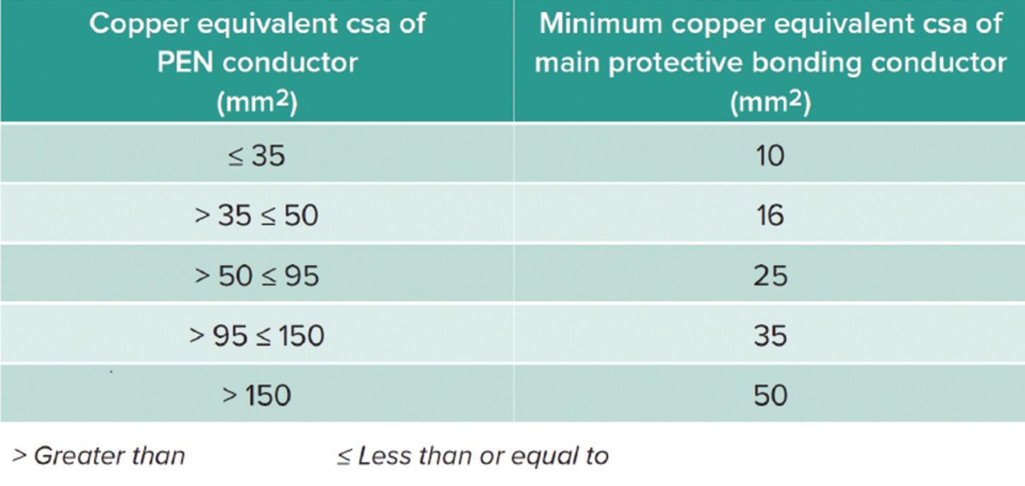
Due to the low earth loop impedance and increased fault currents within a consumer’s installation, typically associated with PME, all main protective bonding conductors must be sized in relation to the PEN conductor of the supply and Table 54 8 of BS 7671, reproduced in Table 1 However, in some cases the local distribution network conditions may require a larger conductor than those listed in Table 1.
Note: Table 54 8 of BS 7671 is also applicable for a PNB system arrangement, a variant to the PME system
Where the PME supply is extended from a dwelling to a detached outbuilding, such as a garage, these bonding requirements will also need to
be applied to any extraneous-conductive parts within that area.
Due to the practicalities for satisfying these bonding requirements at the load end the contractor may decide to convert the earthing arrangement within the garage to a TT system incorporating an earth electrode (542 1 2 3) combined with an appropriate RCD (411.5.2).
Although the TT system earthing arrangement provides less onerous conditions for bonding than that associated with PME, it also presents its own set of issues There is a potential risk of causing damage to other buried services when installing earth electrodes. In addition, the difficulties in providing suitable electrode separation from other buried metalwork connected to the supply PEN conductor
Although the distributor may have initially provided a PME earthing arrangement for an installation, where an addition or alteration is to be made it is the responsibility of the installation designer to assess its suitability and adequacy for the altered circumstances. Where necessary, alternative means of earthing, such as a TT system earthing arrangement, may be used

‘DR. ZZEUS’ TOM BROOKES, md of zzeus training and CHAIRMAN OF THE FSA, ANSWERS YOUR QUESTIONS RELATED TO FIRE SAFETY COMPLIANCE.
In a previous column (December 2023), I answered a question related to the skills of fire alarm and security installers and whether some of the old skills have been lost.
This gave advice on how to measure the resistance of a cable and also how to calculare the resistance of a 1.5 mm standard fire alarm cable.
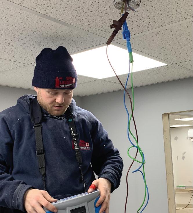
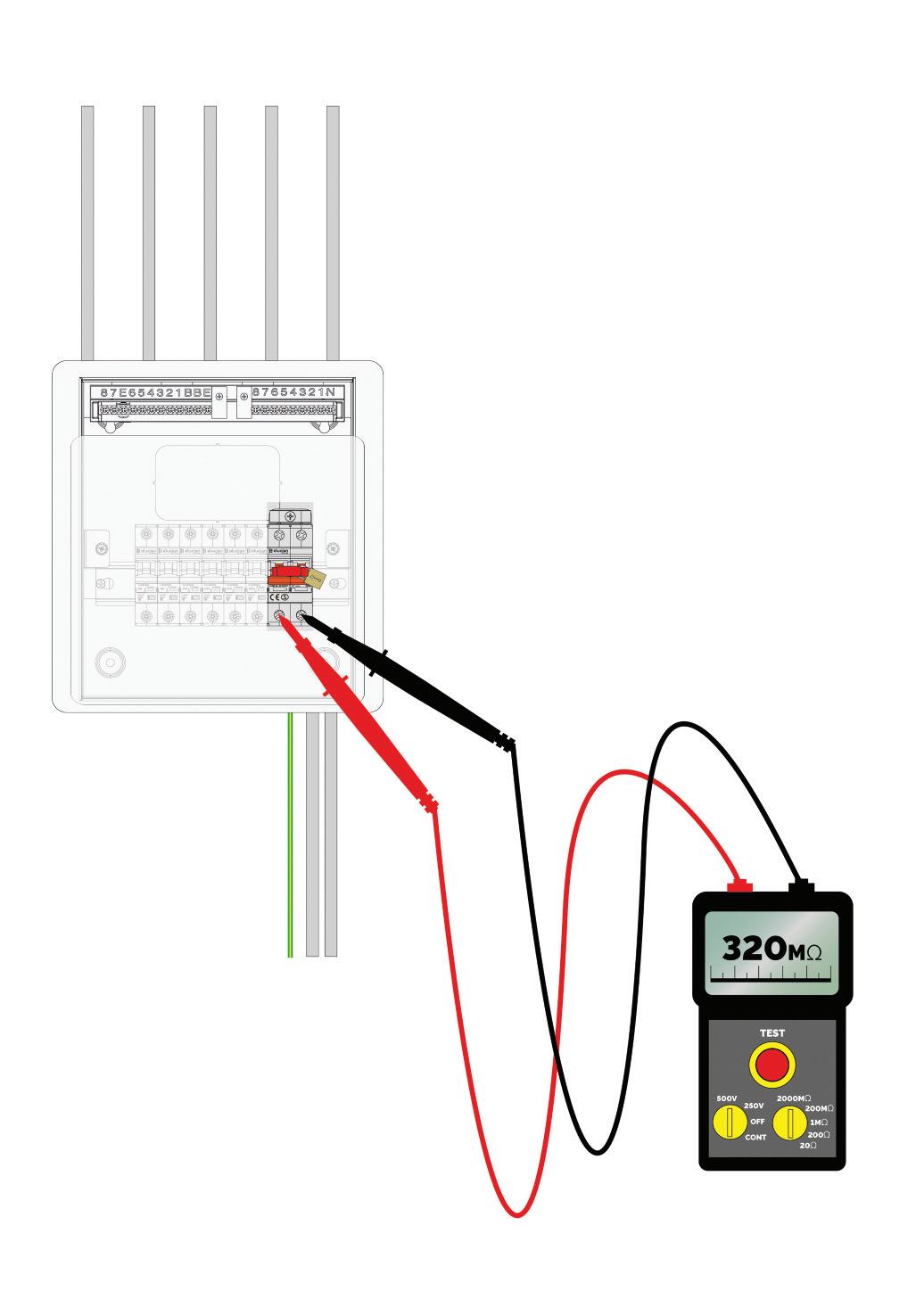
This time around we’re going to answer a final question that relates to the subject: how do you take an insulation reading on a fire cable?
As stated previously, BS 5839-1 clause 38 1 states that all installed cables with a manufacturer’s voltage rating suitable for mains use should be subject to insulation testing at 500 V DC Insulation resistance should be measured between each conductor and earth and achieve no less than 2 MΩ.
It continues to say that on completion of the installation work, where maximum circuit resistance for any circuit is specified by the
manufacturer or supplier, measurement of the resistance of every such circuit must be documented
At Zzeus Training, this is standard day three practical electrical testing, but it may appear that some training providers are not doing this The standard is very clear: if you install a fire cable, you must test it
Insulation resistance testing
Resistance is a measure of how difficult it is for current to flow and is measured in units called ohms (Ω)
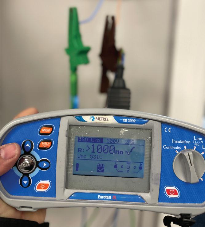
The insulation resistance test definition is the measurement of total resistance between any two points separated by electrical insulation This measurement identifies if, down the length of the tested cable, the insulation between the cores is in good condition The higher the reading, the better the insulation is.
The standard allows 2 MΩ as a minimum reading; however, on brand new soft skin fire cable, I would expect to see a reading greater than the meter


can calculate The new cable with a 2 MΩ reading has got a serious problem
This test needs to be done with no devices on the circuit because it will put 500 V DC through the cable, which may damage equipment or indeed shock a person
Testing for insulation resistance is very simple with a multifunction tester:
Step 1
Attach the live lead to your first core and attach the earth lead to the second core
Step 2
Select ‘Insulation Testing’ on the meter and ensure the test voltage is set at 500 V DC
Step 3
Press the test button, keeping your fingers away from the test leads and cable
The results will measure the resistance in megohms (millions of ohms) Remember, the higher the number, the better the insulation!

DO YOU HAVE A QUESTION YOU'D LIKE ANSWERED? EMAIL YOUR QUERIES TO: TOM@ZZEUS.ORG.UK

GET MORE DETAILS ABOUT ZZEUS TRAINING AND THE RANGE OF COURSES ON OFFER AT: WWW.RDR.LINK/EAZ014












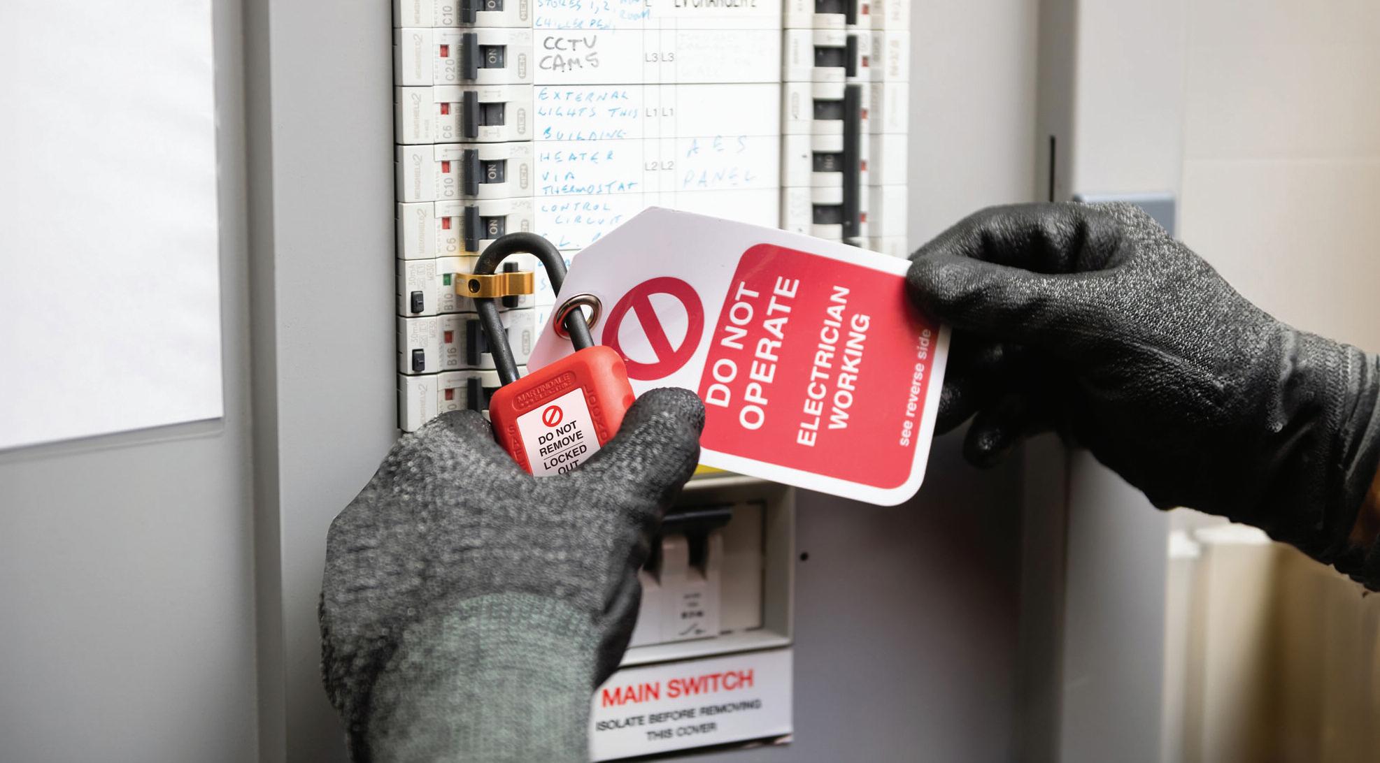

Steve Dunning, Managing Director of Martindale Electric, explains the importance of safe isolation and why using the right equipment is an absolute must.
Safe isolation procedures are necessary to ensure that workers on-site are not exposed to danger when working on or near live electrical systems There have been incidents where failure to use safe isolation procedures has resulted in injury or, in the worst cases, death
Selection and use of the right equipment is one of the most important parts of the procedure. Firstly a voltage indicator with the means to prove it is operational, usually by using a dedicated proving unit Secondly, lock off items suitable for the circuit being tested and signage to warn others Failure to use the correct equipment and procedures can result in a circuit inadvertently remaining live.
Locking off devices are either supplied as individual items or, more generally, as kits There are many kits and combinations available, however a basic starter set should always include a selection of MCB and breaker locks, a padlock with a unique key or combination, a hasp for when more than one person is working on a system, plus an array of lock out tags and warning labels
For the locking off procedure itself, where a distribution board switch or other means of disconnection is used, this should be locked in the ‘off ’ position using a suitable lock with the addition of signage to advise others of the activity The key or combination lock should be the responsibility of the person doing the work or someone delegated by them.
It is important that any padlock must have a unique key or combination held by the person carrying out the work to prevent anyone else from removing the lock and inadvertently activating the circuit A unique key lock provides the safest solution Once the breaker has been locked off correctly, a warning tag should be attached to clearly identify that
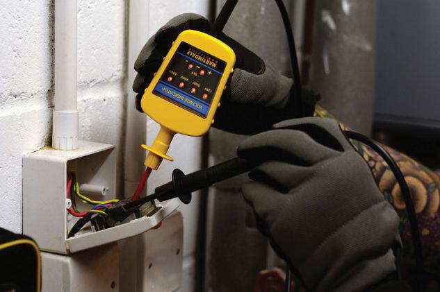
to voltage detectors to be used in contact with electrical systems up to 1000 V AC and HSE Guidance GS38 Electrical test equipment for use on low voltage electrical systems.
Proving dead needs to be done because the circuits to be tested may not be labelled correctly (or labelled at all) and it should never be assumed that a circuit or nearby circuits are dead because the isolation device is set to off.
Best practice is to use a dedicated voltage indicator and a voltage compatible proving unit when carrying out this procedure Importantly the voltage indicator must comply with BS EN61243 There is a variety of suitable equipment available on the market, including test lamps or more commonly voltage
Martindale VI-13800
or VI-15000 Both these units include a high wattage resistor in the probe to limit the current in the event of damage to the cable. It is important to note that the voltage indicator must be able to work without the need for a battery If a device needs a battery and is flat, you cannot prove the circuit is dead
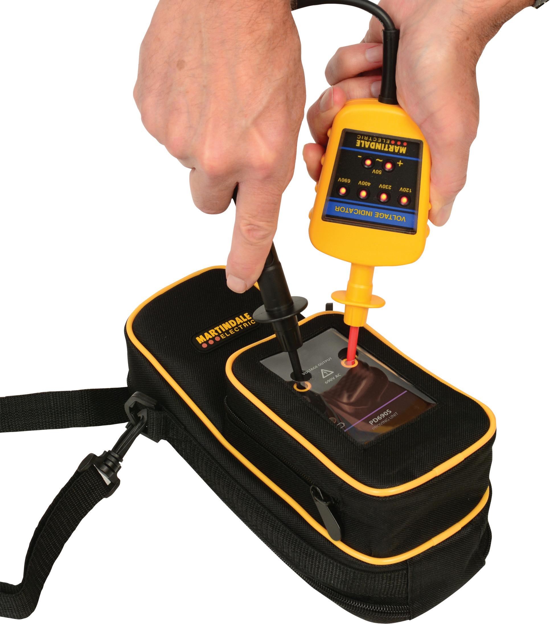
The procedure for proving dead is to take the voltage indicator and check it against a known source, such as a proving unit, then test the circuit before testing the voltage indicator against the known source again to prove the tester has not failed during testing Whilst you can use a known live source to test your voltage indicator, a much safer method is using a dedicated proving unit matched to the
ng used. The reason is wn live source will only the LEDs on the tester, oving unit will ensure that anges are working, ding against incorrect a faulty LED. In addition, s a suitable live source icated proving unit is
ses against the use of and non-contact devices Multimeters are not oving dead process as it elect the wrong range a multimeter relies on unction fully, thus there aking a false “dead” circuit Non-contact also require a battery in and are often sensitive gnals, such as static It’s also not possible to y are working correctly ndard proving unit se units can be used to cables, they cannot used to prove dead.
elines well established solation kits readily mplementing safe cedures is neither pensive and has been es and avoid injury It’s pliance with Electricity at Work Regulations for safe working when installing and maintaining electrical equipment and systems
Electrical Safety First, in association with other industry bodies such as SELECT, has produced a guidance document that covers best practice for safe isolation (Best Practice Guide 2) This includes guidance on proving isolated equipment or circuits are dead by using suitable test lamps and voltage detectors, and is an extremely useful reference document

GET MORE DETAILS ON MARTINDALE ELECTRIC’S ALIVE CAMPAIGN AND ITS RANGE OF PROVING DEVICES AT: WWW.RDR.LINK/EAZ012
For every installation, regardless of the technology, there are requirements placed on the contractor to furnish the client with information on the products and how to use and maintain the system It is important to note that certain items are covered by legislation, British Standards, scheme requirements and consumer protection laws.
During any estimation or quotation for installation contracts, the client may request documentation to demonstrate that you have the relevant skills, insurance and accreditations to satisfy them that you would be suitable to carry out the
This may then form part of the handover documentation as a record that the client has selected the appropriate contractors, which they may need to demonstrate to third-party organisations, such as finance or planning departments
Once the quotation has been accepted, this is often followed by a purchase order and subsequent confirmation by the contractor The client would then expect a programme for the works, risk assessments and method statements for each task, as well as any particular site requirements, such as power shutdowns, delivery and access, as shown in Fig 1


The Construction Design and Management Regulations 2015 (CDM) are statutory regulations that are enforced under the Health and Safety at Work Act The creation of CMD was to establish higher standards in the management and control of construction and demolition work
CDM 2015 has been in force since 6 April 2015, replacing the 2007 CDM Regulations They lay out what people involved in construction work need to do to protect themselves from harm, including anyone the work affects, and for the first time, these regulations are also applicable to domestic installations The aim of CDM 2015 is to improve health and safety in the industry by helping you to:
● Sensibly plan the work so the risks involved are managed from start to finish,
● Have the right people, for the right job, at the right time,
● Cooperate and coordinate your work with others,
● Have the right information about the risks and how they are being managed,
● Communicate this information effectively to those who need to know,
● Consult and engage with workers about the risks and how they are being managed
Members should be aware that:
● All builders, whatever their size, will

have to create a construction phase safety plan for all building projects,
● All domestic projects will have to meet the same basic standards for the provision of welfare facilities as commercial projects,
● Any domestic projects where there has been more than one contractor must have a Health and Safety file presented at completion,
● There is a Health and Safety file/handover pack available, which should include ‘as built’ drawings or specifications of components that have been installed Conveyancing solicitors are likely to request this when a property is bought and sold,
● For home owners, CDM duties are passed to the contractor where there is only one, or to the principal contractor if there are more than one
Where there is more than one contractor, a principal designer will be appointed, and they will coordinate all matters relating to health and safety Where the principal designer changes or is not engaged to the end of a project, any responsibility for the file moves on and may rest finally with the principal contractor.
The principal contractor is responsible for operational site safety and passing information to the principal designer for the Health and Safety file On completion, the principal contractor will hand over the Health and Safety file/handover documentation to the client
There are some caveats associated with CDM, such as the duration and labour associated with the contract, such as:
● Lasts more than 30 days, and
● Has more than 20 people on-site, or
● Lasts more than 500 days
Although these types of contracts would not fall under CDM, as a contractor you will still be required to provide similar handover documentation to the client.
This is to allow them to have the information to enable them to operate, maintain and replace any components
The handover documentation, see Fig 2, should include all documentation relating to the contract, such as:
● Quotations,
● Variations,
● Payments and final settlement,
● Specifications,
● Detailing the extent of the work carried out,
● Health and Safety risk assessment and method statements,
● Certification/commissioning – this is dependent on the scheme ,
● Building Regulation Notifications, where applicable,
● Manufacturers’ warranties (all installed products, including software),
● Manufacturers’ instructions, including maintenance requirements,
● Diagrams and layout drawings for more complex contracts,
● COSHH data sheets for any products used within the installation
This information can take the form of a printed copy, PDF, shared file software or digital file There will also be a requirement for information to be retained in case the client seeks documentation or has a complaint or question regarding the work carried out
Another important area is the case of product recalls, which on occasions may affect a range of equipment and accessories.
As the installer of these products, the manufacturer will contact you regarding product recalls, so having information about where the equipment or accessories were installed is important
The handover pack should include details about product recalls.
It is extremely important that the client is provided with information on how the installation functions, maintenance procedures and replacement of equipment and accessories. Providing the handover pack allows you to discharge your duties to the client and maintain the essential ongoing client relationship

Have you dealt with problems with USB socket-outlets that have been faulty following insulation resistance testing? Jake Green, Head of Technical Engagement with Scolmore Group, aims to shed some light on the issue.
With USB socket-outlets, the charging unit is built into the back of the socket and this is sometimes fixed to the ‘on’ position This means that the switches on the socket that control the 13 A plug element have no connection to the USB charging point, with the result that it is permanently connected
This can cause problems when carrying out insulation resistance testing, as the electronic components of the USB charging unit are part of the circuit and therefore the 500 V that electricians use to test them could damage those components, resulting in a faulty charging port
The Click range of USB sockets has been designed to withstand the 500 V insulation test due to the nature of the circuitry built within the USB socket Chapter 64 of BS 7671 details the general requirements for initial verification, and Section 643 deals with the requirements for testing
Here we briefly consider the requirements for insulation resistance testing and the care that should be taken when testing after second fixing has occurred:
Insulation resistance testing
Insulation resistance testing is carried out to confirm that there are no inadvertent connections between live conductors, and between live conductors and Earth before
the installation is energised (643 3 1)
The insulation resistance test is a ‘dead’ test, and the normal supply should not be ‘live’ To this end the person carrying out the test should ensure that the circuits to be tested are isolated and the normal power cannot be energised inadvertently
The minimum required insulation resistance values in megohms is detailed in Table 64, although a value significantly in excess of these stated values is preferred (643 3 2)
Regulation 641 1 requires that every installation is tested both during erection and on completion before being put into service Insofar as this relates to insulation resistance testing, this means that tests should be carried out after first fixing (after cables have been installed and prior to equipment being connected) This test confirms that the installed cables are in a fit state.
The final insulation resistance test needs to be carried out after second fixing has taken place However, after second fixing it may be that connected equipment may influence the measurement or result of the test (643.3.3). Where this is the case, following the connection of equipment, it is permitted to reduce the test voltage to 250 V DC and to test between the live conductors (connected together) and Earth
Sensitive electronic equipment
The note attached to Regulation 643.3.3

indicates that manufacturer’s instructions may recommend some equipment needs to be disconnected, even when the test voltage is reduced to 250 V DC This may apply, typically, to accessories such as socket-outlets with USB connections and the like
Scolmore’s Click socket-outlets with USB ports do not require disconnecting
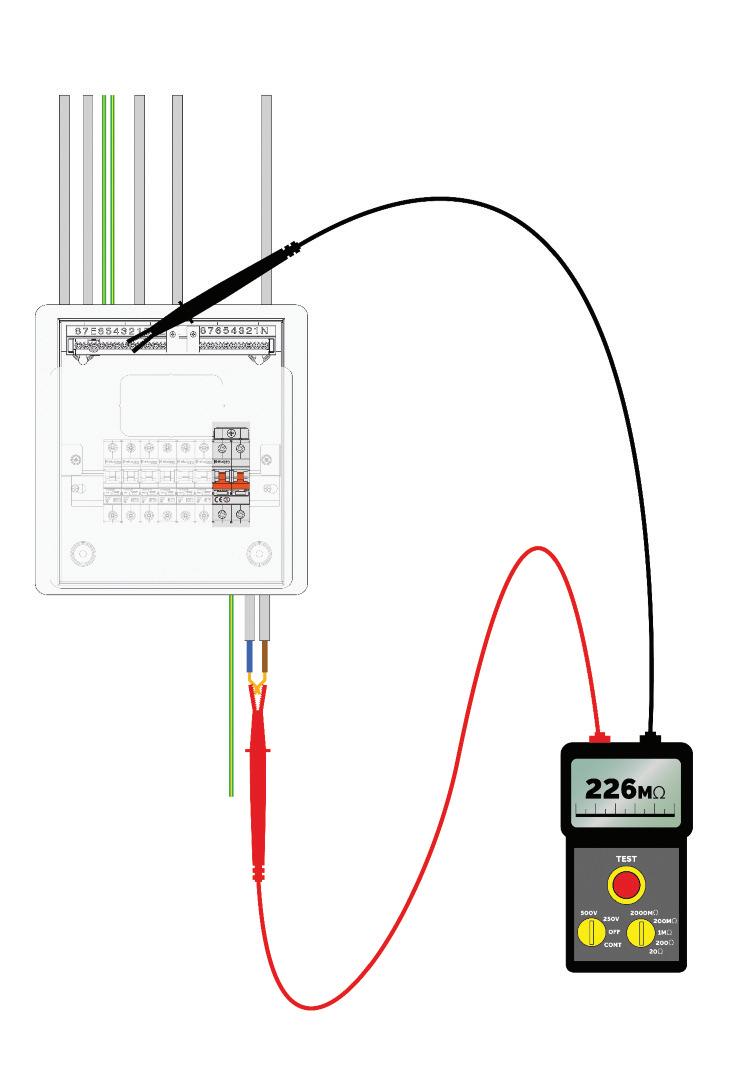

and may be tested between live conductors (connected together) and Earth at a test voltage of 500 V DC whilst still connected in circuit
Conclusion
Insulation resistance testing is an essential part of ensuring that prior to energisation the installation is safe. The tests verify that there are no inadvertent connections between live conductors and between live conductors and Earth
Care should be taken to ensure that any connected equipment is capable of withstanding the test voltages applied
Where there is a risk of damage or test results outside of the permitted range, it may be necessary to disconnect equipment prior to any test being carried out.


What is the ‘Electrician Plus’ campaign that I keep hearing about? Is it a new scheme I will need to join?
In short, no, it’s not an individual accreditation scheme
The term ‘Electrician Plus’ is a concept developed to highlight how the core skills of a qualified electrician are essential to low carbon technology installation. With underpinning core electrical competence, all that is needed is to top-up qualifications in relevant areas such as solar PV, electrical vehicle charging equipment (EVCE) and energy storage systems
It’s essential for public safety that anyone installing such technologies is properly qualified and competent Terms like ‘solar installer’ are not recognised as a separate occupation – those who undertake short courses in these areas without the underpinning core electrical competence can pose a public safety risk, and these people will be installing without robust training and assessment of their electrotechnical skills or knowledge
TESP is working closely with the Building Safety Regulator to finalise the development of the Mandatory Technical Competencies (MTCs) that underpin Competent Persons Schemes New low carbon MTC categories will align with the Electrician Plus model, supporting installation by qualified electricians
Once the MTCs are updated, the Electrotechnical Assessment Specification will also be updated The accompanying EAS Qualifications Guide will also reference valid low carbon qualifications
If you’re already a qualified electrician, there are top-up solar PV, EV and energy storage qualifications from awarding bodies such as City & Guilds, EAL and BPEC They’re designed so that only electricians who meet the industry Level 3 standard can enrol on these courses
The Electrician Plus logo will be used to endorse relevant qualifications to show they are industry approved in terms of content and assessment


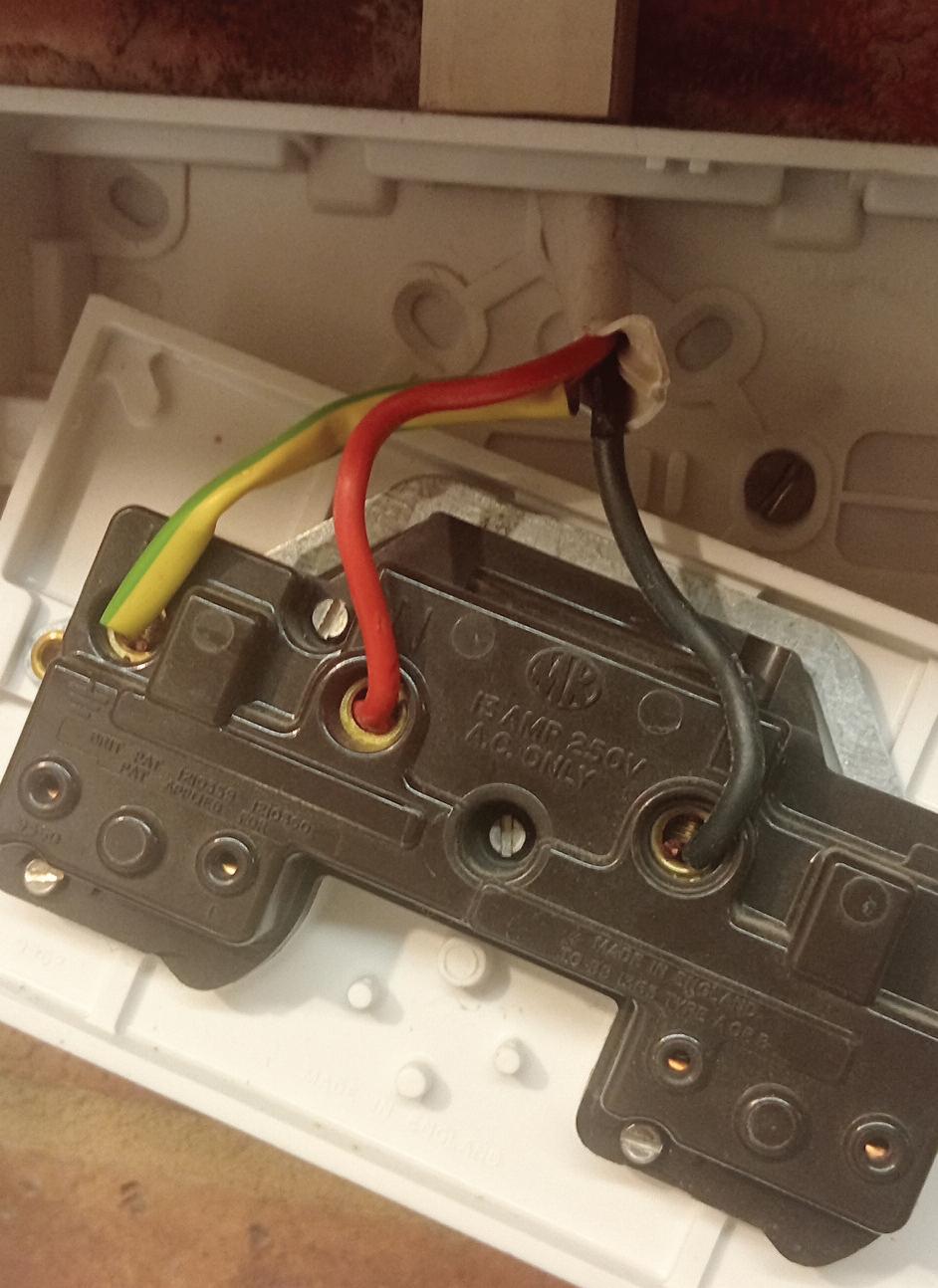
CHRISTOPHER ORTHODOXOU: THE CUSTOMER WAS WONDERING WHY EVERY TIME SHE PLUGGED SOME THING INTO THIS SOCKE T IT WOULD TRIP THE RCD!
This is a failure of the initial verification of the socket- outlet where the correct sequence of inspection and testing has not been carried out Par t of the requirements for inspection under Par t 6 for initial verification Regulation 642 3 (i) requires the check ing of the connection of conductors If this had been carried out then the incorrect termination of the line conductor into the neutral terminal and vice versa would have been noticed and corrected
The requirements for testing under Section 643 should have revealed the cross-polarity under several of the Regulations as follows:
● Regulation 643 2 Continuity of Conductors – R1 + R2 testing would have revealed the issue.
● Regulation 643 6 Polarity – this test would have shown that the line and neutral conductors were incorrectly connected at the socket- outlet
● Regulation 643 7 1 Ear th Fault Loop Impedance – this test would have highlighted that the polarity was incorrect
Unfor tunately, there are occasions when DIY enthusiasts dabble in electrical work without the k nowledge or experience, instead often relying on guidance from “How to Guides”
What would be inexcusable were if this work was carried out by a sk illed electrical person as they have paid lip ser vice to the requirement of Electricity at Work Regulations and BS 7671 requirements for electrical installations.


Updated for BS 7671:2018+A2:2022, NAPIT ’s EICR Codebreakers publication is purpose -written to aid contractors, inspectors and clients, and now includes updates to align with Amendment 2 of the IE T 18th Edition Wiring Regulations The book is the per fect technical aid for electrical professionals and their customers.


Need help with cracking those all-impor tant EICR codes? Ever y month the technical team at NAPIT will be studying your latest ‘Caught on Camera’ photos and offering advice on the next steps, should you find a similar installation. If you want the team at NAPIT to help crack your codes then send your pic tures through to us at: pe@hamer ville.co.uk


DARREN OVEREND: I SAW THIS UK CONVERTER PLUG ON SOME CHRISTMAS LIGHTS THAT HAD A EUROPEAN ST YLE TRANSFORMER PLUG HOW'S THAT SUPPOSED TO WORK THEN?
As electricians we often come across a wide variety of electrical equipment for use within an electrical installation Sometimes it is the client that provides the products either via an online purchase, bargain purchase from a market stall or from a holiday purchase.
I t is relatively easy to ascer tain if an item of fixed electrical equipment is compliant with the product standards as these have to be connected into the wiring system The flexible nature of socket- outlets and any product which is supplied with a 13 A plug is out of the control of the electrician, as it often appears when we leave site or, in this case, Christmas lights which make an annual appearance
It would be during either a periodic inspection when carr ying out an EICR or when under taking a por table appliance testing programme that these types of items are discovered
The BS 1363 series:2023 for plugs, socket- outlets, adaptors and connections is vital to ensuring that the millions of plugs, sockets and adaptors, made by many different manufacturers, are safe to use and will fit together and function correctly and reliably, even after many inser tions


The item shown in the image would not meet any of the requirements of BS 1363 series, even though it may work in some socket- outlets where the line, neutral and ear th aper tures operate in conjunction with each other From the image it is not clear if there is a provision of a fuse which is also a requirement of BS 1363 series.
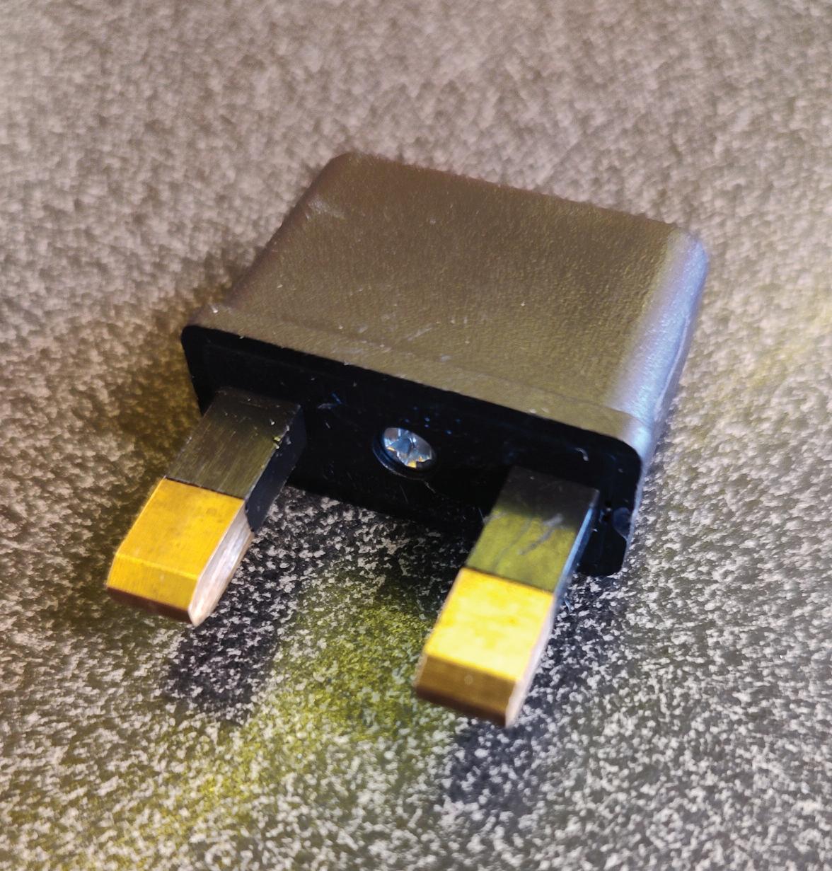


The A2:2022 18th Edition Codebreakers publication is priced at £22.00 (members) and £24.00 (non-members). It is available in both hard copy and digital versions * Price is VAT exempt and excludes postage and packaging.

ORDER YOUR COPY OF NAPIT CODEBREAKERS BY VISITING: WWW.RDR.LINK/EAZ009





This article from the experts at NICEIC provides guidance on the use of the metallic armouring of a cable as a circuit protective conductor (cpc), main protective bonding conductor or where practicable, an earthing conductor.
Although the main purpose of the metallic armouring is to provide mechanical protection, it may also be used as a protective conductor if all the relevant requirements of BS 7671 for such use are satisfied
Use as a circuit protective conductor (cpc)
Where the armouring of a cable is used as a cpc it is likely to experience some thermal stress (heating effects) when subjected to earth fault current The ability to withstand such stress safely will depend upon the cross-sectional area (csa) of the armouring used as a cpc, which must not be less than that determined by one of the two methods referred to in regulation 543.1.1 of BS 7671, either by calculation or selection:
● Using the formula given in regulation 543 1 3 based on the adiabatic expression This provides a more accurate method of determining the minimum csa required for the cpc.
S = √I 2 t = mm2 k
● Using Table 54 7 of BS 7671 for selection, when permitted, and as an alternative to calculation. This will consequently produce a larger
required minimum csa Where the application of Table 54 7 produces a non-standard size it will be necessary to select a conductor with a larger csa
Selection is dependent on the csa of the line conductor and the associated ‘k’ value for both the line and cpc conductors, providing the minimum csa required for the cpc However, where the line conductors are sized only by considerations of short-circuit current or where the earth fault current is expected to be less than the short-circuit current the method of selection must not be used (543 1 1)
Where the armouring of the cable is to be used as a cpc, careful consideration must be given to its end-to-end impedance as this will contribute to the earth fault loop impedance (Zs) at the exposed-conductive-parts of all Class I electrical equipment connected to the circuit. As such, the value of Zs at all relevant parts, including the cable armouring, glands and terminations, need to be sufficiently low to satisfy the requirements of BS 7671 for fault protection
Use as a main protective bonding conductor
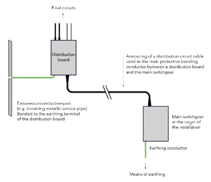
The armouring of a cable may be used as a main protective bonding conductor
With reference to Fig 1, the distribution board is supplied from the main switchgear at the origin of the installation by an armoured cable In addition, an extraneous-conductive-part is bonded to the main earthing terminal (MET) of the distribution board
The armouring is therefore both the circuit protective conductor for the circuit supplying the distribution board and the main protective bonding conductor between the distribution board and the main switchgear
In an installation where Protective Multiple Earthing (PME) conditions apply, the main protective bonding conductors
“When using the armouring as a protective conductor its csa must satisfy the minimum size required for the application, using either the method of calculation or selection as Table 54.7.”
may have to carry sustained ‘diverted neutral’ currents in the event of an open PEN (protective earth and neutral) conductor. This may result in the heating of bonding conductors in the installation, including the armouring
For this reason, the armouring of a cable should not be used as a main protective bonding conductor unless it has been determined by the installation designer that under such circumstances, the heat produced in the armouring is not liable to cause overheating of the live conductors or cause damage to conductor insulation
Where PME conditions apply and the armouring is to be used as a main protective bonding conductor, it must be selected in relation to the PEN conductor of the supply and have a csa of not less than the minimum required by Table 54 8 of regulation 544 1 1
Note: Where steel armouring is used for the main protective bonding conductor its csa would typically be required to be 8 0 times that of copper in order to afford an equivalent conductance
The earthing conductor is defined as a protective conductor connecting the main earthing terminal of an installation to an earth electrode or to other means of earthing Armouring is not commonly used as an earthing conductor based on the sizing practicality issues, although BS 7671 does not preclude such use. Every earthing conductor is required to
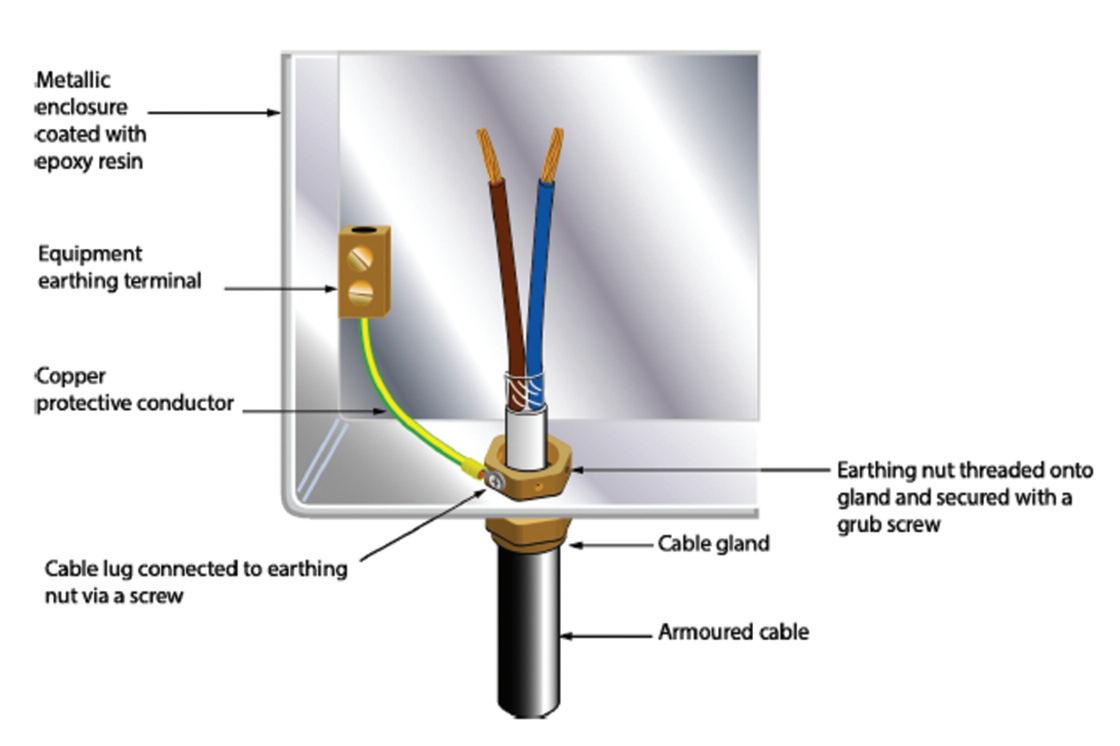
have a csa not less than that given by one of the two methods referred to in regulation 543 1 1 In addition, where PME conditions apply, the csa of the armouring must also be sufficient to meet the requirements for a main protective bonding conductor (542 3 1)
Preservation of electrical continuity
It is a requirement of regulation 543 3 1 that all protective conductors should be provided with suitable protection against:
● Mechanical damage and vibration,
● Chemical deterioration and corrosion, and
● Electrodynamics effects (mechanical forces experienced during fault currents)
In addition to those requirements previously mentioned, regulation 543 2 5 states where the metallic covering, including armouring, is used as a cpc for the associated circuit it must satisfy both requirements (i) and (ii) of regulation 543 2 2, including:
(i) The need to ensure electrical continuity, either by its construction or suitable connection, and (ii) The cross-sectional-area shall be at least equal to that resulting from the application of regulation 543 1 or be verified by test
Where the armouring is used as a protective conductor appropriate cable glands must be used for terminating cable
ends and be suitable for the installed environment, as shown in Fig 2
Furthermore, electrical joints such as those between the armouring, cable glands and earthing terminals, must be properly made (mechanically and electrically), and where necessary, suitably protected
Note: To prevent degradation of cable insulation, bonding clamps to BS 951 or worm-drive type hose clamps should not be used to provide a direct connection to the armouring of a cable
Summary
When using the armouring as a protective conductor its csa must satisfy the minimum size required for the application, using either the method of calculation or selection as Table 54 7
The continuity of the armouring must be assured for its method of installation while using suitable cable glands and installation methods. Were necessary protection must be provided against the risk of deterioration as a result from mechanical, chemical or electrochemical effects

The team at ROBUS offers advice on how electricians and electrical professionals should respond to the age-old conundrum of how long LEDs really last.
The question around the length of time that LEDs will last is one that you will almost certainly be asked – whether it comes from a client, a colleague, an apprentice, or perhaps it might be the million-pound question if you one day end up on Who Wants to be a Millionaire?
The introduction of LED light sources into the lighting market resulted in many exaggerated claims about the amount of light they emit and their longevity But, with respect to the facts, let’s dig into the real measurement of the LED lifecycle.
LEDs don’t last forever
The graph (pictured below) shows how different light sources perform over time Although each technology experiences losses at a differing rate, all of them experience a decrease in efficiency How can we measure and define this for LED luminaires as a standard throughout the lighting market? That is the very purpose of TM-21
TM-21: the long-term lumen maintenance method
TM-21 is the globally accepted method for projecting the long-term lumen maintenance of an LED light source In
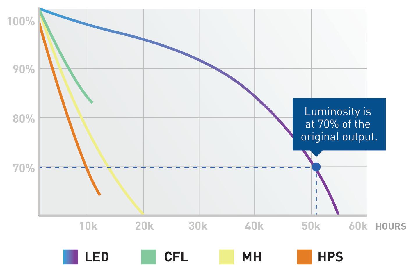
other words, how long LEDs last. The TM-21 method uses lumen depreciation data, also called LM-80, to make these projections That’s quite a collection of abbreviations! To begin with, we need to clarify what LM-80 represents
How to measure lumen depreciation
LM-80 is the collection of lumen depreciation data for at least 6,000 hours, but how does it work in practice? LED suppliers test their LEDs (in batches of 20/30 units) for 6,000 hours and measure the lumen depreciation every 1,000 hours
For example: a sample quantity of 20 units, tested for 9,000 hours at a temperature of 25°C can have the results extrapolated to 5 5 times their value The same test, when run on 30 units allows for an extrapolation to 6 times their value For instance, 6 x 9,000 hours = 54,000 hours At ROBUS, we always round this down to 50,000 hours
The above data establishes the benchmark used to define the useable life of the LED product in hours
This data is put into the TM-21 system, and this is how the expected lifetime of an LED can be deduced. The method produces several useful values that provide insights into how long the LEDs should last These values are known as L-values, B-values, C-values, and F-values
L-value: measures luminous flux and colour maintenance
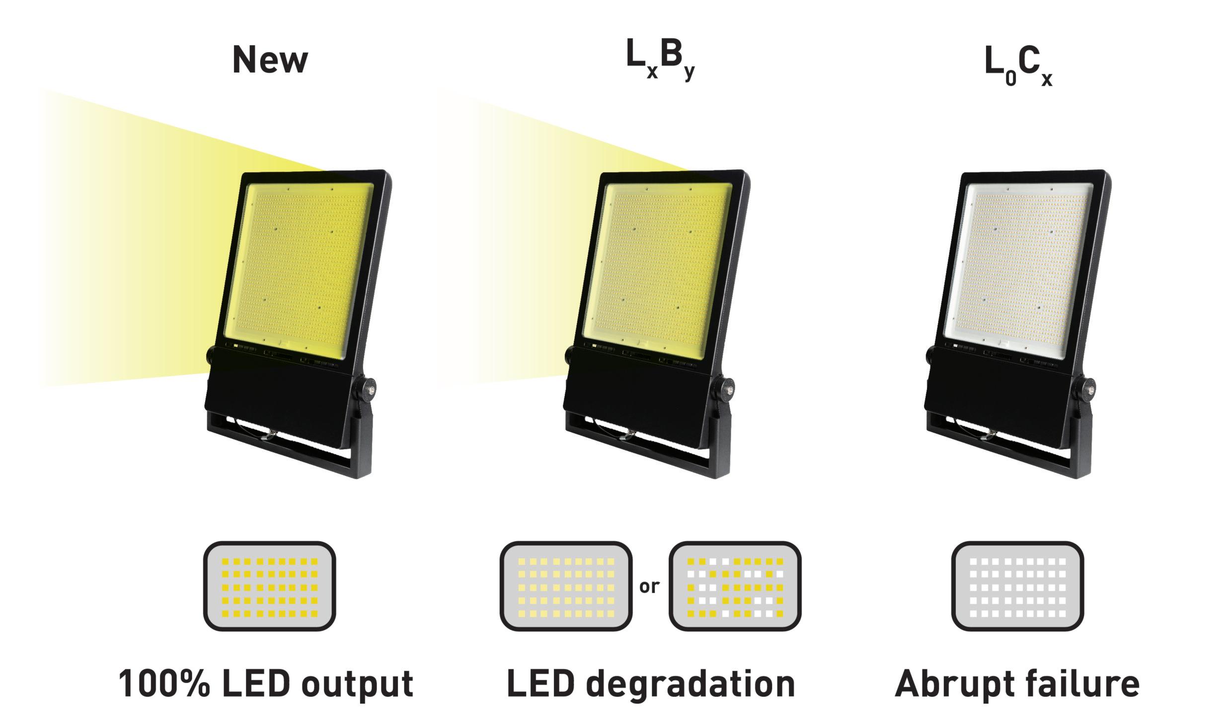
The L-value (lumen maintenance value) indicates the expected decline in light efficiency over a specific duration
Humans can discern changes in light levels when the light output is reduced to 70% of the initial lumens, which is why at ROBUS we use L70 as our standard
For example: a typical 1,000 Lm product, rated at 50,000 hours, could produce as little as 700 Lm by the time 50,000 hours have elapsed. Therefore, it retains 70% of its initial brightness and loses 30% of its light output The L-value in this example would be labelled as L70
One action you may take would be to increase the number of LEDs by 30% after 50,000 hours to ensure 1,000 Lm are maintained.
B-value: the failure percentage
B - v a l u e i n d i c a t e s t h e v a r i a t i o n o f t h e
e x p e c t e d l u m e n l e v e l a t t h e s p e c i f i e d
h o u r s T h i s v a l u e i s d i r e c t l y r e l a t e d t o t h e
L - v a l u e. W h e n t h e B - v a l u e i s B 5 0 a n d t h e
L - v a l u e i s L 7 0, i t m e a n s t h a t w e c a n
a n t i c i p a t e t h a t 5 0 % o f t h e L E D s w i l l n o t
m e e t t h e L 7 0 t h r e s h o l d
H o w d o w e a s s e s s B - v a l u e s?
G e n e r a l l y, i s i t n o t t e s t e d b e c a u s e t h e
p r o d u c t w o u l d n e e d t o r u n f o r t h e f u l l
d u r a t i o n a s r e s u l t s c a n’ t b e r e l i a b l y
e x t r a p o l a t e d i .e. a 5 0,0 0 0 h o u r p r o d u c t
w o u l d r e q u i r e a s i x - y e a r t e s t !
T h e r e f o r e, B - v a l u e s o f t e n g o
u n t e s t e d I n s t e a d , t h e i n d u s t r y t y p i c a l l y
d e f i n e s t h e m b a s e d o n d a t a f r o m T M - 2 1 .
C-value: percentage of catastrophic failures
The C-value represents the anticipated percentage of catastrophic failures during the LED’s lifetime A catastrophic failure is when the LED ceases to produce any light. It is worth noting, the failure of a single or several LEDs in a cluster isn’t included in this value as these are accounted for by the B-value
For instance, the C-value can be C10 or lower C10 would mean that after the specified duration, 10% of the LEDs might have experienced catastrophic failure. The C-value for standard LEDs is often much lower and in the range of 1%, and as such, it is often disregarded and not disclosed for indoor products
F-value: combination of B and C Some manufacturers of LED luminaires
may use the F-value instead of B and C values The F-value is a sum of the B and C values:
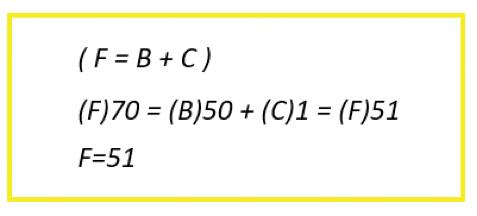
Summary
So, how long do LEDs really last? The quickest answer can be found in the technical specifications of the product, but it is worth noting that when a specifications sheet mentions XX,000 hours it isn’t the true lifespan – it’s what LEDs are tested to.
The key is to choose a supplier whose information you can trust as, unfortunately, it is possible to manipulate these numbers These specifications typically include the hours of lamp life, and for reputable suppliers like ROBUS, this information is obtained through the TM-21 method.
But, for your winning Who Wants to be a Millionaire? answer, you can rightly say that it depends on its daily usage!

DOWNLOAD OR BROWSE THE NEW ROBUS CATALOGUE AT:


This article looks at Chapter 82 of BS 7671 and embedded renewable sources, either used in conjunction with the existing supply for an installation or as an alternative and independent source of electrical energy forming a prosumer’s low-voltage electrical installation (PEI).
Many consumers have been moving towards energy saving measures over the past few years, and never more so than recently with the increasing costs in energy and the significantly reduced returns provided from feeding back into the Grid
The increase in the popularity of electric vehicles in line with government targets for the reduction in the burning of fossil fuels for energy generation, and delays in the construction of nuclear power facilities has meant that measures need to be taken to support the increasing energy demands and mitigate stress on the public distribution network
Amendment 2 of BS 7671:2018 introduced a new Chapter 82; Prosumer’s low voltage electrical installations (PEIs), which contains additional requirements, recommendations and guidance for the design, erection, and verification of many types of low voltage electrical installations included within the scope
of BS 7671, and not least, for those installations having local production and storage of electrical energy (see Fig 1)
The intention of Chapter 82 is to ensure that the adopted means of renewable energy source(s) available
and operating in a PEI, either in isolation from, or when connected in parallel with, the public supply and used for the dynamic support of power demand to the public distribution network should be made reliable, be able to operate
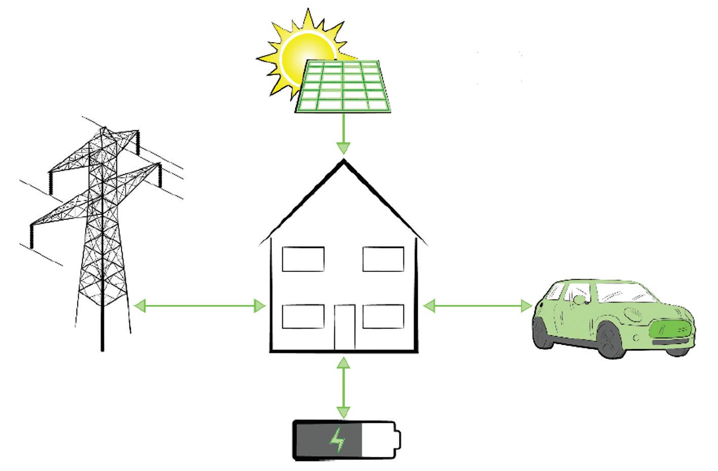
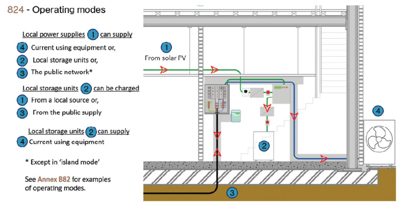
safely, and provide sustainable and efficient use of energy when integrated into the smart grid system.
Additionally, the PEI infrastructure should be compatible with existing and future ways to deliver electrical energy to current-using equipment within the installation and/or to the public distribution network (821)
It is recognised that both the generation of electrical energy from renewable sources such as solar PV and/or wind turbines, and that energy consumption patterns within an installation are intermittent For this reason, where it is expected that a prosumer’s installation is to be available in ‘Island mode’ and isolated from the grid, or where it is necessary to maximise self-consumption during periods of reduced generation and high current demand, regulation 822 1 recommends that a means to store energy is provided within a PEI.
What is a PEI?
A PEI is a low-voltage electrical installation that can both consume and produce electrical energy, and that may or may not be connected to a public distribution network. A PEI is typically formed by a combination of electrical equipment available within an installation that provides specific functions, including:
I. Supply: Connection to the public distribution network, or local generation
including Solar PV, wind turbines and in some instances, electrical energy storage systems (EESS).
II Distribution system: Depending on the type of PEI, configuration of distribution boards, distribution and final circuits may vary The delivery method could be through the public distribution system (if agreed with the DNO) or within the separate PEI distribution system
III. Consumption: Current-using equipment used within the installation A battery should be considered as both a supply and a load (see note to regulation 823).
IV Energy management: System monitoring within the installation, allowing switching between available supplies and control of connected loads in the form of load shedding.
PEI operational modes
The integrated electrical energy management system (EEMS) of the PEI is able to switch between the readily available sources of supply Regulation 824.2 highlights the operational modes that may be adopted and implemented for a particular type of PEI, including:
● Connected mode – operation relies on a connection to the public supply network to enable:
● direct feeding mode: the public distribution network supplies the PEI to consume energy (see Annex B82 1 1, B82 2 1, B82 3 1), and
● reverse feeding mode: the PEI supplies the public distribution network by means of the embedded generation and/or electrical energy storage system (see Annex B82 1 3, B82 2 3, B82 3 3)
● Island mode – the PEI is disconnected and isolated from the public distribution system but remains energized through the solar PV and EESS (if any) (see Annex B82 1 2, B82 2 2, B82 3 2 and Fig 2)
The electrical energy management system (EEMS) is an intelligent device capable of monitoring and controlling many functions (825 1) and may comprise a separate unit or be integrated in other equipment within the PEI The EEMS can exchange and receive live data with the Distribution
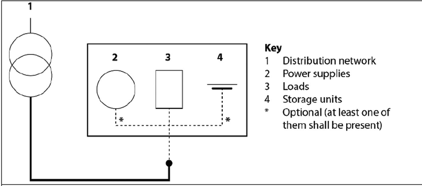
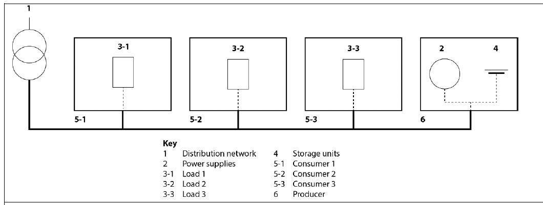
System Operator (DSO) in order to interact with the dynamic needs for power demand of the distribution network and current demand within the installation
In response, the EEMS can adapt the PEI accordingly by means of balancing local consumption, often through load shedding, although other equipment may be required, and diverting electrical energy, depending upon local sources of supply available and their readiness to supply either the installation or support the distribution network.
The EEMS is configured during the initial set-up and contains information relating to the local energy sources attached to the PEI, as agreed within the contractual agreement between the DSO and user For example, some installations may have a solar PV system combined with a static EESS, whilst other systems may include a connection for an electric vehicle (EV) operating either as a load or mobile EESS
Appendix 17 of BS 7671 provides additional recommendations for the design and erection of electrical installations having local production and energy storage to optimise the overall efficient use of electricity (821).
The means for optimisation and the application of an energy efficiency measure such as load shedding is typically incorporated as a function within the EEMS controlling the PEI However, in all cases, the design of the PEI and functions of the EEMS must take account of the needs of the user as priority to the functionality of the PEI over those needs of the DSO for dynamic support of the grid
Paragraph 17 2 (iv) of Appendix 17 states that provision for a manual override facility enabling the user to take control from such automatic functions should be considered during the system design This may take the form of a dedicated user interface
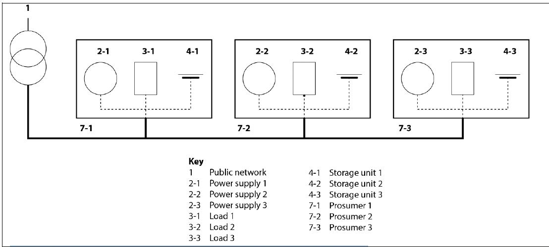
The system design must also ensure that there is no reduction in the availability of an electrical supply or service/operation of the installation below the desired level of the user
For example, it may include the need to recharge an EV at the property after a long journey However, at the time, the installation is found to be operating in island mode at the request of the DSO during a period of high demand on the network To enable EV charging, the EEMS would be required to switch the installation back to connected mode, either automatically, or manually at the request of the user
It is recognised that a PEI can switch between the intended operational modes at any time (824 2) Although, the form of embedded generation must be automatically synchronised in terms of frequency, phase, and voltage magnitude with the public distribution network before reconnecting back to the grid, and provided that the requirements of Section 551 are met
The operating modes as described earlier in the article may be adopted for specific types of PEI characterised as:
● Individual – one electrical installation with the ability to both consume and supply electrical energy (see Fig 3)
● Collective – a group of prosumers relying on a communal source of energy generation which is managed for the group (see Fig 4)
● Shared – multiple prosumers coordinating their individual supplies to form a common source of shared energy (see Fig 5)
This article introduced the concept of a prosumer’s low voltage electrical installation and explained the different types of operational modes within a PEI Also considered was the electrical energy management system (EEMS), used as a means of monitoring and control of a PEI, while maintaining the user as central to the operation of the PEI.


When carrying out an EICR it never fails to amaze me the level of poor workmanship, and the disregard for fundamental electrical safety
In this case the images provided were extensive but, due to space, we can only review a small selection of them here. We may revisit some of the others at a later date
Often the observations we encounter during an EICR would be subject to non-compliances which would give rise to danger, although the majority are items which haven’t been correctly installed in the first place
The image on the right has a protective bonding conductor that hasn’t be correctly terminated, supported or provided with a safety label The conductor is resting on the incoming water service pipe.
The image on the left reveals an ear th electrode connection which has not been provided with protection against mechanical damage or external influences.

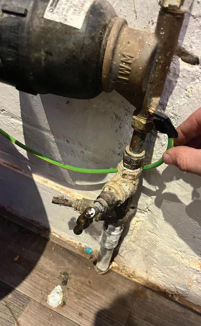

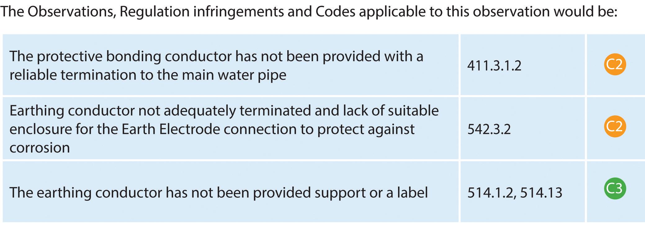

GET THE BOOK AND CRACK THOSE CODES! Updated for BS 7671:2018+A2:2022, NAPIT ’s EICR Codebreakers publication is purpose -written to aid contractors, inspectors and clients, and now includes updates to align with Amendment 2 of the IE T 18th Edition Wiring Regulations The book is the per fect technical aid for electrical professionals and their customers.


Need help with cracking those all-impor tant EICR codes? Ever y month the technical team at NAPIT will be studying your latest ‘Caught on Camera’ photos and offering advice on the next steps, should you find a similar installation. If you want the team at NAPIT to help crack your codes then send your pic tures through to us at: pe@hamer ville.co.uk


HAMMOND ELECTRICS: WE FOUND THIS ON A RECENT EICR WHAT ’S YOUR OPINION/ADVICE?
Par t of the changes that were introduced under BS 7671:2018+A2:2022 were the changes in the Schedule of Inspections for Distributor or Supplier ’s equipment This (under item 1 0) relates to any inadequacies that were encountered and the inspector must inform the Client, Duty Holder or the person ordering the work of the issues found.
This change was brought to allow EICRs to be issued as Satisfactor y where only obser vations found in the par ts of the electrical installation where the inspector has no control or responsibility such as the Distributor or Supplier ’s equipment. This is where the outcome of any obser vations in section 1.1 would be noted with an X
Unfor tunately, with this image there are exposed live par ts where the meter tails from the ser vice cut- out fuse to the meter have not been suitably protected due to the lack of a cover to prevent contact with the Line or Neutral supply terminations
The large hole on the right hand side of the enclosure, should the cover be in place, would also allow access to the live par ts.
This is an area where the Client, Duty Holder or the person ordering the works would require immediate notification to allow the dangerous situation to be rectified
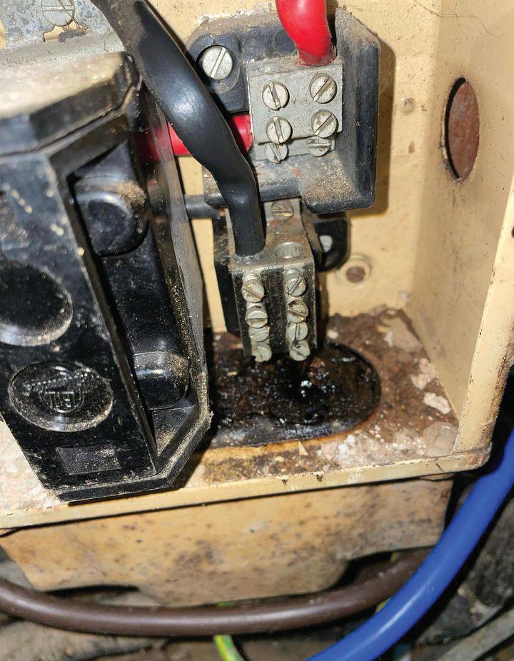

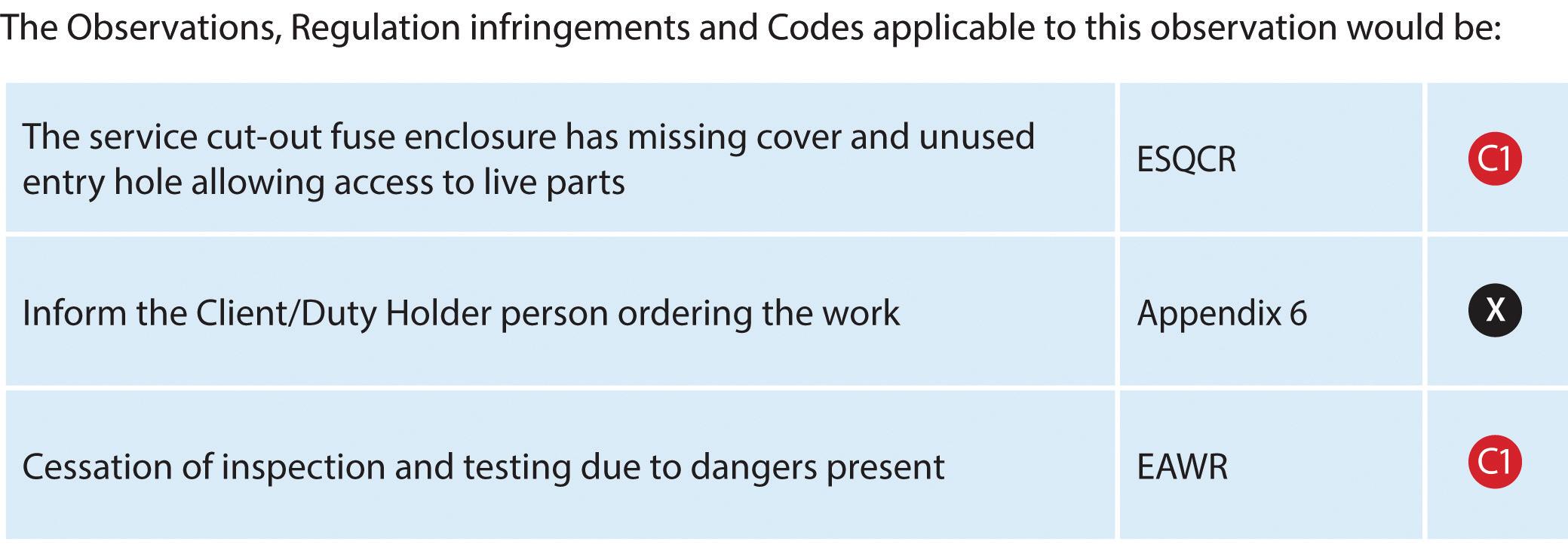


In these circumstances, it would have been appropriate to cease the inspection and testing of the installation due to the dangers to the inspection team, unless the danger was removed. ORDER YOUR
The A2:2022 18th Edition Codebreakers publication is priced at £22.00 (members) and £24.00 (non-members). It is available in both hard copy and digital versions * Price is VAT exempt and excludes postage and packaging.





The Construction Industry Scheme (CIS) is a pivotal aspect of tax compliance, setting out specific rules for how contractors must handle payments made to subcontractors for construction work. Kevin Thomas of the Indigo Group explains more.
CIS applies primarily to contractors and subcontractors
i n t h e c o n s t r u c t i o n i n d u s t r y
H o w e v e r, t h e d e f i n i t i o n o f
w h o f a l l s u n d e r t h e s e
c a t e g o r i e s c a n b e b r o a d e r
t h a n a n t i c i p a t e d . Yo u m u s t
r e g i s t e r a s a c o n t r a c t o r i f y o u ’ v e s p e n t
m o r e t h a n £ 3 m i l l i o n o n c o n s t r u c t i o n i n
t h e 1 2 m o n t h s s i n c e y o u m a d e y o u r f i r s t
p a y m e n t – e v e n i f y o u r b u s i n e s s d o e s n’ t
c a r r y o u t c o n s t r u c t i o n w o r k T h i s
i n c l u d e s c o m p a n i e s l i ke p r o p e r t y
d e v e l o p e r s a n d b u i l d i n g f i r m s , b u t a l s o
e x t e n d s t o g o v e r n m e n t d e p a r t m e n t s a n d
l o c a l a u t h o r i t i e s t h a t e n g a g e i n
c o n s t r u c t i o n w o r k
Even sectors like retail and entertainment, if they spend significantly on construction, fall under the CIS umbrella.
What are subcontractors?
Subcontractors are entities or individuals who agree to undertake part of the work contracted by the main contractor It's crucial for subcontractors to register for CIS to avoid higher tax deductions from their payments
There is no specific turnover threshold for subcontractors However, their status in terms of tax deductions depends on their registration with HMRC Those registered under CIS are subject to a standard 20% tax deduction on their invoices, while
unregistered subcontractors face a higher 30% deduction
However, subcontractors who meet specific criteria can apply for gross payment status, allowing them to receive full payment without deductions, though they must pass certain financial and compliance tests to qualify
Navigating CIS tax compliance
As a contractor, it's your responsibility to ensure that your business complies with CIS tax regulations This involves a series of steps, which begins with registering for the scheme
Here’s what you need to know and do: 1 Register for CIS
2. Verify your subcontractors: Before making any payments, it’s crucial to verify your subcontractors with HMRC This process will determine the tax deduction rate: 20% for registered subcontractors, 30% for those unregistered, or 0% for subcontractors with gross payment status
3. Deduct and pay taxes: When you pay subcontractors, deduct the tax amount as per their status and pay it to HMRC

This deduction serves as an advance towards the subcontractor's tax and National Insurance
4. Record keeping: Maintain detailed records of all the payments and deductions made under the CIS for at least three years. These records are vital for any HMRC inspections and for your tax returns
5. Submit monthly returns: Submit CIS returns monthly to HMRC, reporting all the payments made to subcontractors and tax deducted.
Subcontractor responsibilities
As a subcontractor, compliance with CIS is equally important Here’s what you should expect and do:
1. Register with HMRC: Ensure you’re registered with HMRC for CIS to avoid higher tax deductions from your payments (30% instead of 20%)
2. Keep records: Maintain accurate records of all your invoices and the tax deducted by contractors These records are essential for completing your annual Self-Assessment tax return
3. Understand deductions: Know that the taxes deducted by contractors are not a final payment of your tax and National Insurance You need to declare your income and expenses in your Self-Assessment tax return, after which HMRC will calculate your final tax bill or refund
4. Gross payment status: If eligible, apply for gross payment status This allows you to receive your payments without upfront tax deductions, but it requires you to pass certain financial and compliance tests
Further help
For contractors, the administrative burden of CIS compliance can be
overwhelming, especially when managing multiple subcontractors. This is where Indigo Group can help with its ‘Contract’ service, tailored specifically for contractors in the construction industry
As a Commercial Contractor, Indigo takes on all responsibilities for the subcontractor. This means registering them under CIS is Indigo’s responsibility, removing any admin and compliance burden from a business
The company also takes over the cumbersome process of verifying subcontractors, calculating and processing tax deductions and submitting monthly returns, freeing up valuable time for contractors to focus on their core business activities


In this article, the technical experts at NAPIT examine the practice of burying cables.
Two of the most commonly asked questions in this industry must be: “Can I bury this cable?” and “How deep does it need to go?”
The answer to both questions will vary wildly based on the cable type, the installation, the external influences, the traffic over it (both motorised and on foot) and the need for future access
Some cables are designed specifically to be buried and have their own extra protection, such as steel wire armoured (SWA), as displayed in Fig 1 Other cable types can be buried, but may need a little extra protection to ensure they remain as free as possible from damage
Where cables have no external protection, such as the armouring of an SWA cable, we have to take a different approach to protect the inner cores from being buried and being subjected to excessive stress We can still bury them, but we have to protect them either by way of some form of ducting, conduit or a protected channel.
In reality, cables in ducting, conduit and
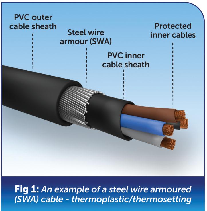
protected channels, although buried, are usually accessible for maintenance or completely encased in concrete – see BS 7671 Appendix 4, Table 4A2 and reference methods 59 and 60, respectively
We usually see protected channels in plant rooms and where cables enter under a distribution board, and we must ensure that we have access to them to carry out future maintenance, alterations and possible repairs
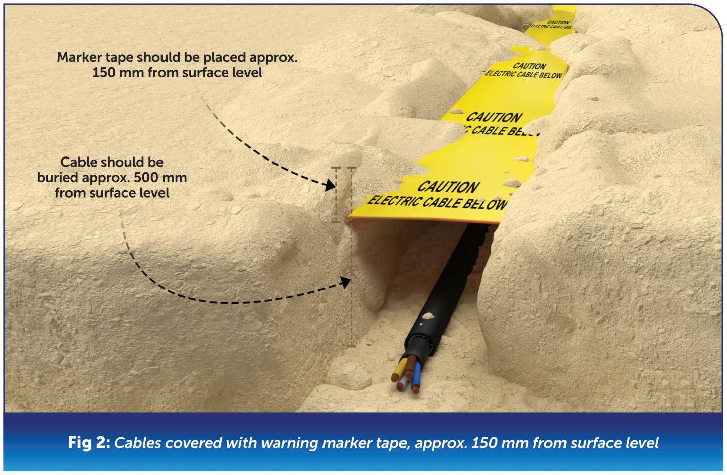
Where long runs of buried cable are anticipated and the area is likely to have either foot or motorised traffic over it, SWA is the go-to cable It was designed for this very purpose, and where installed correctly, it meets all of the requirements for water ingress protection and object damage caused by stress loadings from aggregate buried on top of it
Twin and earth in a hose pipe are unlikely to fit the mechanical damage or water submergence requirements;

remember, the ground is an unforgiving environment, and twin and earth cables often don’t fare well in it
Plus, when digging, if a client comes across a hose pipe, many people take for granted that it’s just an old, buried, unwanted hose pipe and crash through it with a shovel or fork – that’s exactly what we don’t want to happen
What do the Regulations say about burying cables, generally?
As a general rule, BS 7671 doesn’t give much advice or particulars other than Regulation 522 8 10 stating that a cable must be adequately protected and at a depth unlikely to lead to a disturbance during natural overground traffic and use
Traffic doesn’t necessarily mean vehicular in this instance and can be anything from general footfall to gardening Along with the depth of a buried cable, it needs to be adequately identified using a marker tape or similar, see Fig 2 As a general rule, marker tape should be laid approximately 150 mm from the finished surface level.
Where an SWA cable is buried directly in the ground, it should be backfilled with a sand aggregate to help cushion and protect it from the effects of larger aggregates damaging it when buried, as shown in Fig 3
So that’s about it from a general cable-burying perspective BS 7671 leaves pretty much everything open to designers to put together an adequate system
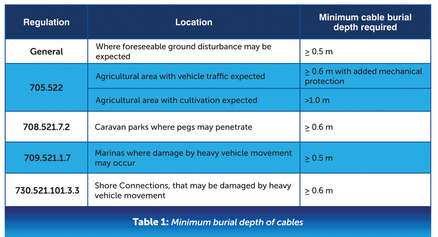
based on the risks that are present in different installations and their uses
What are the specific Regulations for buried cables?
When we look at the risk an installation and its use may give rise to, BS 7671 only looks at four different areas where specific cable depth provisions are given These areas are covered in Part 7 special locations, which include:
705: Agricultural and horticultural premises
708: Electrical installations in caravan/camping parks and similar locations
709: Marinas and similar locations
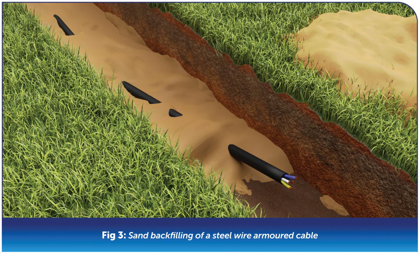
730: Onshore units of electrical shore connections for inland navigation vessels
We can see the requirements for each of these special locations more clearly when we look at them in a table which breaks down each Regulation specifically See Table 1 for minimum buried cable depth requirements
Along with the general Regulation for buried cables, 522 8 10, and the special locations listed earlier in this article, guidance is also available in BS 7671 Appendix 4 Table 4A2 installation and reference methods
Table 4A2 gives various reference methods, clarifies how to construct the different systems, and refers to the correct current carrying capacity that any cable conductors would then be subjected to
So, in conclusion, there is no simple answer, depth, or method. It is really down to the designer, the installation, its use, and any risks that may be prevalent
The one figure that we all agree on as an industry, is that any buried cable should be at a minimum depth of 0 5 m, where a special location requirement does not cover it. This is because with light hand digging, such as in a garden, etc , we may subject a cable (even an armoured one) to damage at depths of less than 0 5 m

Natasha King, Product Manager at Vent-Axia, explains more about the requirements of the amended Approved Document Part F and how electricians can meet them.

Amended Approved Document Part F (Means of Ventilation) of the Building Regulations is seen as a vital step to improve indoor air quality (IAQ) as we head towards the Future Homes Standard on the road to net zero
For electricians working in existing homes the amended document means that when carrying out energy efficiency measures to an existing dwelling they now need to assess if any extra ventilation is required to comply
Amended Part F marked a ‘step change’ for ventilation when it was published in December 2021. Previously, ventilation had taken a back seat to the need for improved energy efficiency in our homes to meet carbon emission targets As a result, we’ve all seen what happens when sealing up homes to make them more energy efficient without considering ventilation – increased indoor air pollution. The most visible sign of this is
condensation and mould, but this is only the tip of the iceberg since homes with indoor air pollution can contain over 900 chemical and biological contaminants in the air we breathe Part F has therefore started to redress the balance of ventilation with energy efficiency with a focus on the importance of good IAQ to health and wellbeing
What does this mean for electricians? A key addition to Approved Document F: Volume 1 for electricians is a new sub section ‘Installing Energy Efficiency Measures’ in existing properties Here it sets out that:
“When carrying out energy efficiency measures to an existing dwelling, an
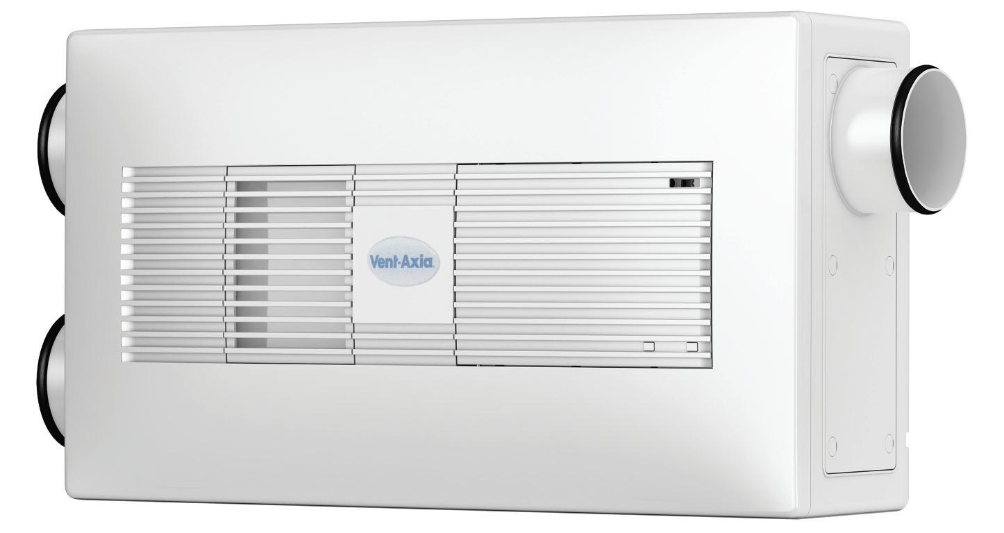

assessment should determine what, if any, additional ventilation provision is needed, based on the estimated impact of the work.”
Part F provides two options for calculating these new ventilation requirements, the first is the simplified method which covers most properties, the second is seeking expert advice
The simplified method involves counting the energy efficiency measures that have been added and then using Table 3 1 in Approved Document F: Volume 1 to classify whether they are minor or major Homes are then allocated to Category A, B, or C depending on the number of minor and major measures,
with A the lowest and C the highest The category then determines what ventilation is required Electricians should be aware that Category C natural ventilation does not comply with Part F without a full design by a competent person
An important point to note here is electricians have to consider the energy efficiency measures that have been made since the home was built, as well as ones that are planned.
Since the UK has an ageing housing stock where many homes may have been fitted in the past with double glazing, insulation or had chimneys sealed up, it can be difficult to determine exactly how many energy efficiency measures may

have been added to a dwelling. This could lead to an electrician inadvertently fitting intermittent ventilation in what they think is a Category B home but instead it is a Category C and, as a result, it will not provide sufficient ventilation to protect the occupants’ health, risking poor IAQ, condensation and mould.
A simple solution to comply with Approved Document F: Volume 1 is for electricians to choose continuous ventilation for existing homes, since it is compliant with both category B and C and is the easiest and safest way of complying every time
There are also huge benefits to moving to a continuous running ventilation system for customers since the fan will operate at a low speed, continuously maintaining good IAQ and if boost is required, it will be at a lower level compared to an intermittent fan This means lower power consumption and noise levels
Approved Document F gives detailed guidance on required levels of airflow needed by room and house size and should be followed when selecting a fan. There is a wide range of different types of continuous ventilation to choose from to ensure exactly the right solution
For electricians aiming to help landlords tackle condensation and mould and improve IAQ, there are also continuous ventilation options aimed specifically at social housing, while another solution for deeper refurbishment of properties including habitable rooms, such as bedrooms and living areas, combines continuous ventilation with heat recovery BROWSE VENT-AXIA’S PRODUCT SELECTOR BROCHURE ONLINE AT:


During an EICR there are often several obser vations that almost defy belief that such blatant disregard for basic electrical safety has been shown on items that have been installed and cer tificated on a regular basis
Pic 1 has the usual missing blanks which can allow access to live par ts, which is fur ther compounded by the introduction of non- compatible protective devices
Pic 2 has a CU with a main switch which has been subject to thermal damage on the incoming neutral conductor. This may be a case of a loose connection, overloading or potential diver ted neutral current.
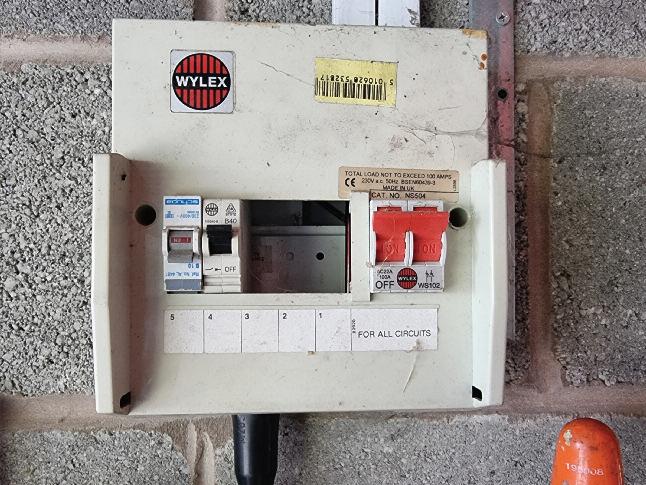
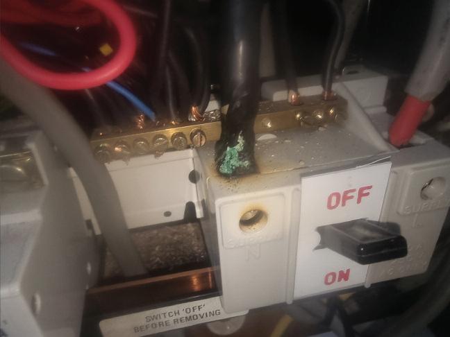

Additionally, the T&E cable installed through the live busbar and also in contact with the neutral terminal block in the consumer unit
In Pic 3 we have a car tridge fuse style CU with a missing cover which allows access to live par ts. There’s also the addition of an RCD mounted external to the consumer unit on the block work without an appropriate enclosure This also has exposed live par ts
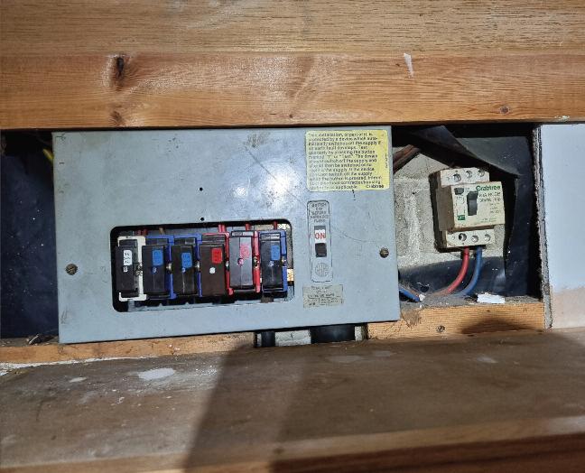
Pic 4 would appear to be a ser vice cut- out fuse with a solid copper core bridging the fuse holder contacts – this offers no overcurrent or fault protection Although the ser vice cut- out fuse isn’t par t of the inspection process of an EICR, this shows that reliance on what is stated on the fuse holder regarding the rating of the fuse and whether it may not be what is actually installed.

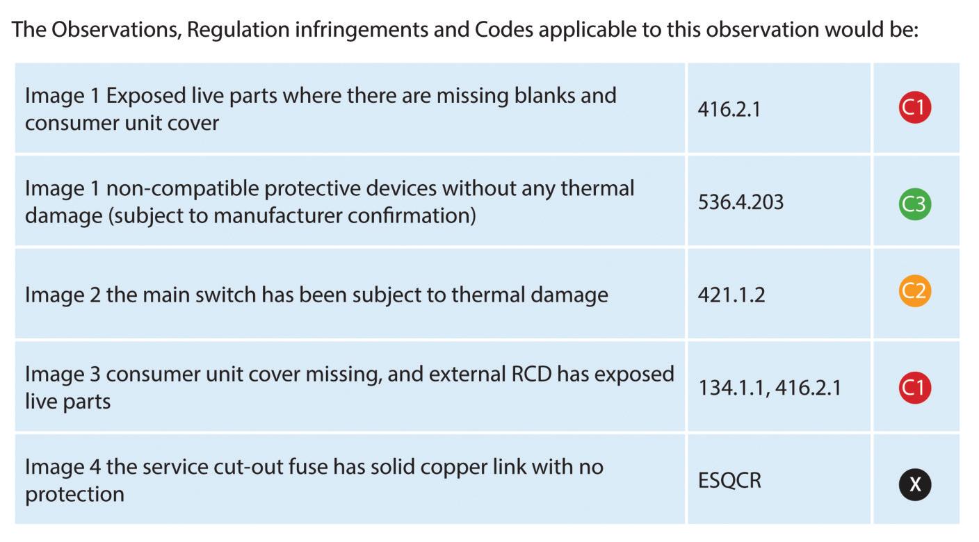
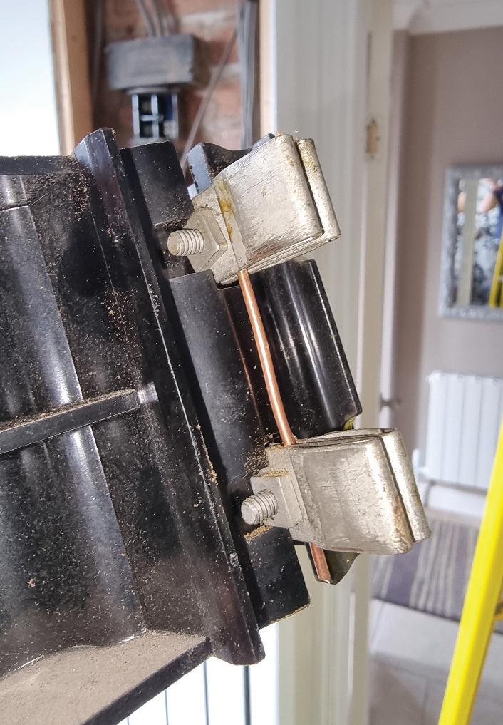

Updated for BS 7671:2018+A2:2022, NAPIT ’s EICR Codebreakers publication is purpose -written to aid contractors, inspectors and clients, and now includes updates to align with Amendment 2 of the IE T 18th Edition Wiring Regulations The book is the per fect technical aid for electrical professionals and their customers.


Need help with cracking those all-impor tant EICR codes? Ever y month the technical team at NAPIT will be studying your latest ‘Caught on Camera’ photos and offering advice on the next steps, should you find a similar installation. If you want the team at NAPIT to help crack your codes then send your pic tures through to us at: pe@hamer ville.co.uk


IAIN NORMAN: WE WERE RECENTLY ASKED TO PROVIDE A 32 A SUPPLY FOR THE FIRST OF MANY SMALL SAUNAS TO BE INSTALLED BY OUR CUSTOMER YOU CAN IMAGINE OUR SURPRISE, THEN ,TO FIND THEY EXPEC TED A PLUG ON OUR END IT WOULD SEEM THE MANUFAC TURER HAD NOT NOTICED THIS BEFORE AND HAD SOLD MANY SAUNAS ALREADY HAVING BEEN INFORMED OF THE PROBLEM, THEY WILL NOW BUILD THE SAUNAS WITH A PLUG I WONDER HOW MANY ARE ALREADY INSTALLED WITH A PLUG ON THE SUPPLY LEAD?
With any item of electrical equipment that has been supplied by a client for connection by an electrical contractor, it ’s expected that the information provided with regards to the characteristics of such equipment is sufficient to allow the correct design of the circuit, including any external influences
A final circuit is installed to connect current-using equipment either directly or by socket- outlet or other connection units The provision in this case of a BS EN 60309-2/BS 4343 230 V 32 A socket- outlet as the means of termination for the sauna to the final circuit does not provide a suitable means to connect. To allow connection to this socket- outlet via a BS EN 60309-2/BS 4343 plug connected to the final circuit would result in the pins of the plug being exposed live par ts
If a socket- outlet is used for the final circuit termination then the appropriate plug for connection to that socket- outlet shall be used.
Regulation 553 1 201 details that BS 1363 socket- outlets for household use are preferable and the ver y nature of BS EN 60309-2/BS 4343 being intended for industrial use
The socket- outlet appears to be a IP44 splashproof version when the external location may require IP67 waterproof
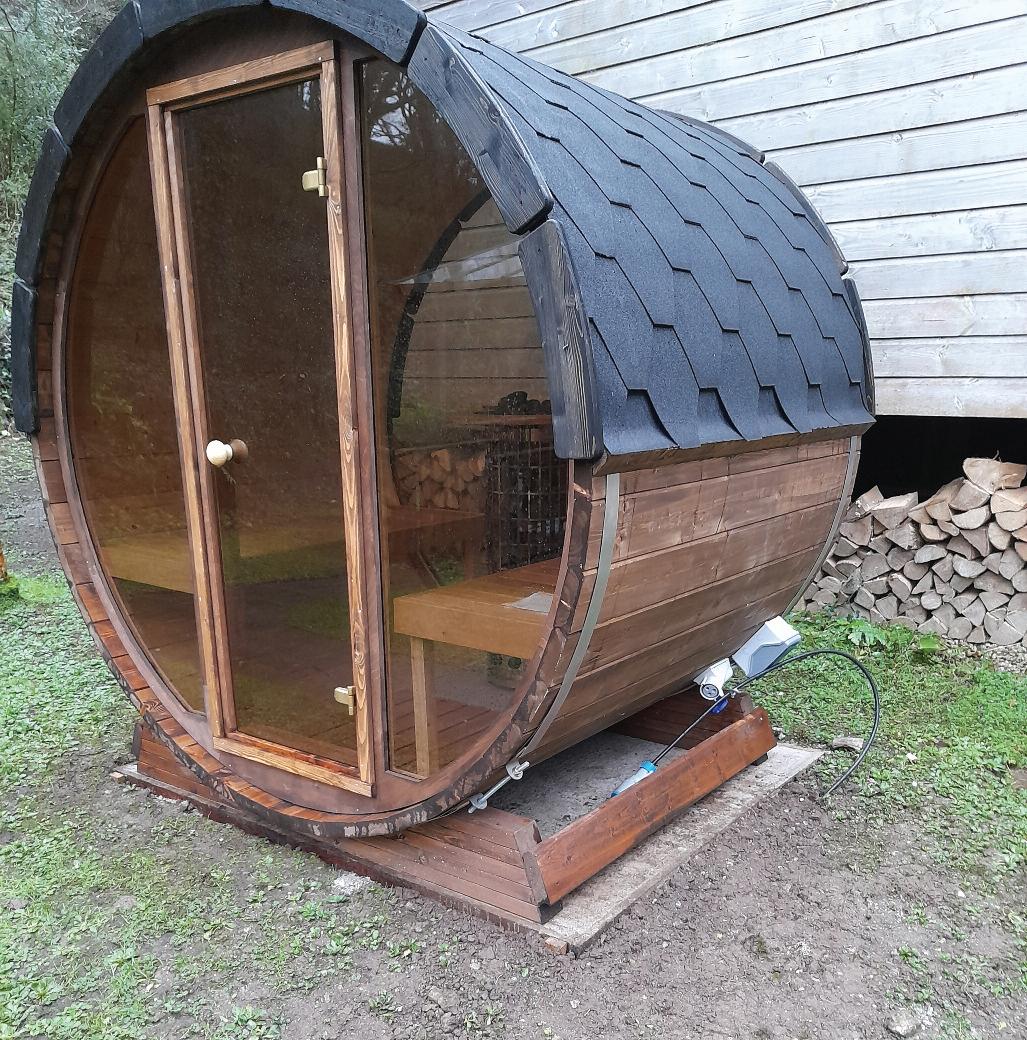

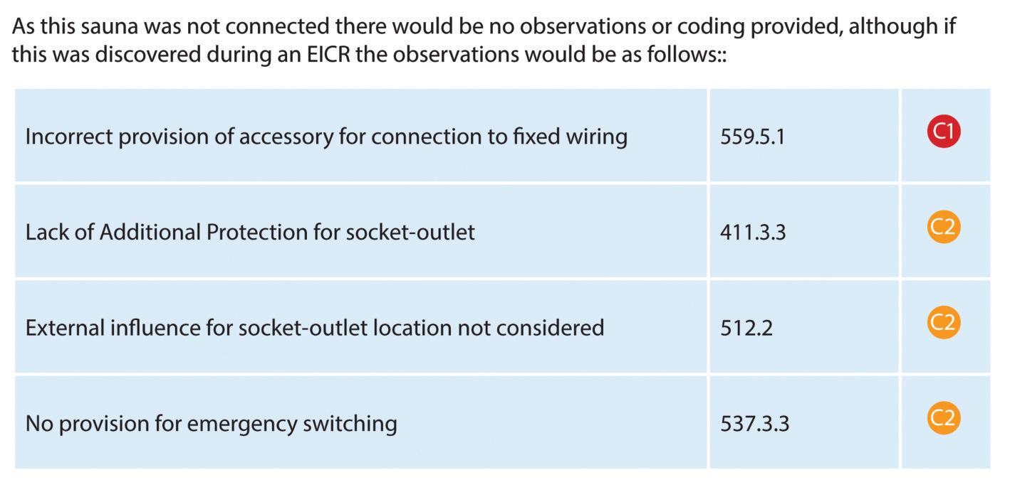
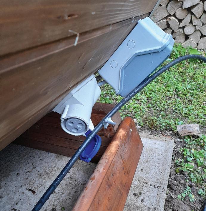


There has been no provision of a means to disconnect the equipment for emergenc y switching ORDER YOUR COPY OF NAPIT
The A2:2022 18th Edition Codebreakers publication is priced at £22.00 (members) and £24.00 (non-members). It is available in both hard copy and digital versions * Price is VAT exempt and excludes postage and packaging.


Section 443 of BS 7671:2018+A2:2022 contains requirements for protection against transient overvoltages either of atmospheric origin or due to switching. Where the application of overvoltage protection measures are required, regulation 443.1 specifies that any surge protective devices (SPDs) should be selected and erected in accordance with Section 534 of that standard. This article looks at the types of SPD recognised by BS 7671 and their location within an installation.
SPDs can be used to provide protection against transient overvoltages either of atmospheric origin (443 4 1) or due to switching (443.4.2).
Within DD CLC/TS 61643-12:2009 Surge protective devices connected to low-voltage power distribution systems Selection and application principles, Clause 4 (systems and equipment to be protected) advises that the following two factors need to be considered when evaluating an installation in respect of the use of SPDs:
● the characteristics of the low-voltage power distribution system on which it will be used, including expected types and levels of overvoltage and current:
● system earthing arrangement (TN-S, TN-C-S, TT, IT etc )
● nominal voltage
● cause of the overvoltage (lightning, switching or temporary overvoltage); and
● the characteristics of the equipment
requiring protection:
● the rated impulse withstand of the equipment, tested in accordance with EN 60664-1; and
● the impulse immunity of the equipment, tested in accordance with EN 61000-4-5
Based on the aforementioned, suitable Types of SPD may be selected for use at appropriate points within the installation
Classification of SPD Type relates to the tests the device must be able to meet
The test requirements for SPDs for power systems shall comply with BS EN 61643-11:2012+A11:2018
Low-voltage surge protective devices
Surge protective devices connected to low-voltage power distribution systems
Requirements and test methods
There are three classes of tests The
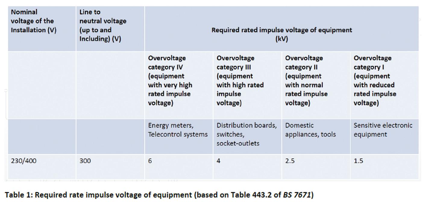
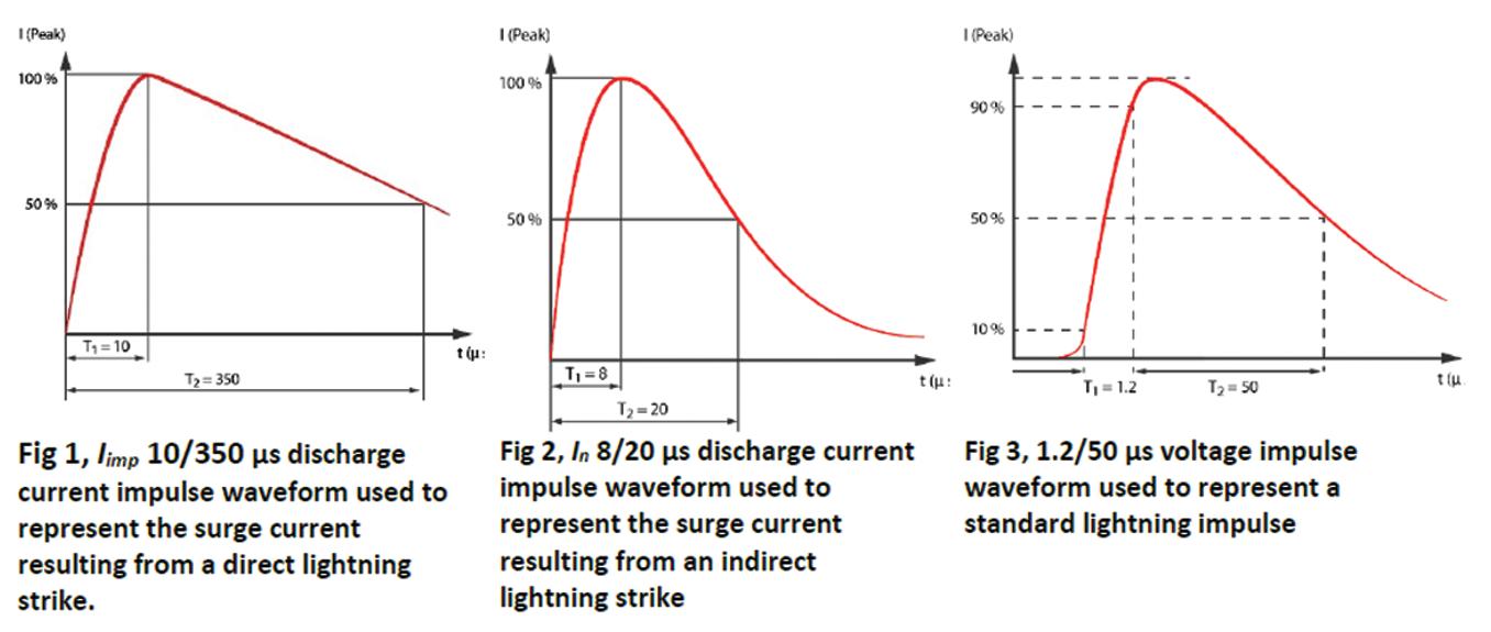
introduction to BS EN 61643-11:2012+A11:2018 advises that the Class I test is intended to simulate partial conducted lightning current impulses, while the Class II and Class III tests involve impulses of shorter duration.
Class I tests are carried out with a 10/350 μs current impulse, as shown in Fig 1 (Clause E 5 of BS EN 62305 1:2011) This represents a standard lightning impulse
For Class II, tests are carried out with the normal discharge current In 8/20 μs voltage impulse (see Fig 2)
For Class III, tests are carried out with a 1 2/50 μs voltage 8/20 μs current combination wave generator (see Fig 3)
An SPD may be classified according to more than one test class Where this is the case, the tests required for all declared test classes shall be applied to the device
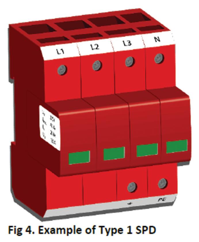
Type 1 SPDs, meeting test Class I, are designed to divert high surge currents associated with direct lightning strikes to earth safely and limit the transient overvoltage to prevent damage to the installation wiring and connected equipment They also protect against risks to human life
Where protection against high surge currents associated with direct lightning strikes is required, for example when a building has a structural Lightning Protection System (LPS) or an overhead line at risk of direct strike, Type 1 power SPDs should be installed as close as possible at each origin (534 4 1 3) or point of entry of an electrical service into the electrical installation (534 4 1 6) (see Fig 4)
Type 2 SPDs, meeting test Class II, when located at the origin of the electrical
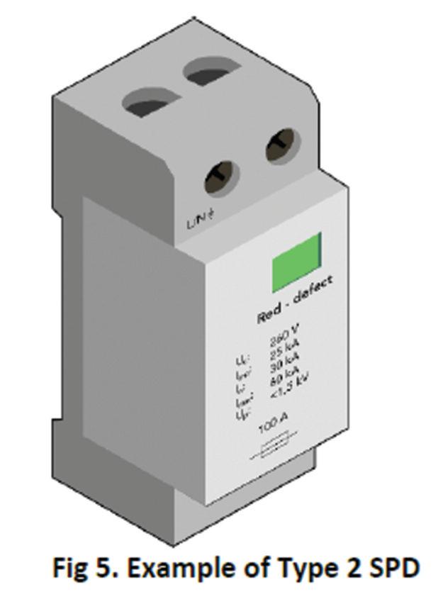
installation address the risk of overvoltage arising from an indirect lightning strike, limiting the transient overvoltage to levels which are safe for connected equipment
Such an arrangement is suitable for installations in locations where direct lightning strikes are unlikely, such as in built-up urban areas
Where an installation does not have a LPS installed and does not require protection against the effects of direct lightning, a Type 2 SPD shall be installed as close as possible to the origin(s) of the electrical installation (534.4.1.4).
In industrial installations, Type 2 SPDs may be installed on sub-distribution boards or closer to the equipment to be protected, downstream from Type 1 and/or Type 2 SPDs installed at the origin of the installation (534.4.1.5) (see Fig 5).
Sensitive equipment within the installation may benefit from protection provided by a Type 3 SPD in addition to that provided by Type 1 and/or 2 SPDs
Section 534 recognises SPDs as Type 3 where the voltage protection level (denoted by Up on the SPDs labelling) is lower than the susceptibility threshold of sensitive equipment
It should be noted that Type 3 SPDs should only be installed in installations where Types 1 and/or 2 SPDs are present upstream of their intended position
They may be installed within sub-distribution boards (typically Type 2+3 SPDs), near or within items of equipment deemed susceptible to damage from overvoltage (534 4 1 5), or in fixed socket-outlets or mobile socket-outlet trailing leads
“Sensitive equipment within the installation may benefit from protection provided by a Type 3 SPD in addition to that provided by Type 1 and/or Type 2 SPDs.”
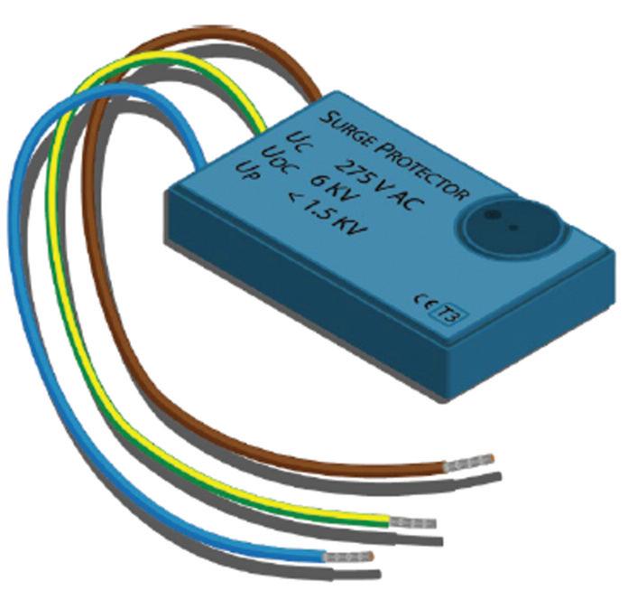

Type 3 SPDs may also protect equipment from switching transients originating from within the premises (see Fig 6).
Combined Type SPDs (e.g. Type 1+2, Type 1+2+3)
An SPD may be classified according to more than one test class (for example, test class I (T1) and test class II (T2)). In this case, the tests required for all declared test classes shall be performed Type 1+2 SPDs are installed close to the intake position, such as at the first distribution board, in buildings which are at risk of direct lightning strike having a lightning protection system and/or are fed by an overhead line.
Rated impulse voltages and equipment overvoltage categories
In respect of overvoltages entering the installation at its origin, the amplitude of that overvoltage will be most severe close to the origin, with the amplitude falling as the electrical installation extends into the premises
Electrical equipment within an installation shall have a rated impulse voltage not less than the value given for its overvoltage category in Table 443 2 of BS 7671. Table 1 of this article, based on Table 443 2, describes the required impulse voltages of equipment for a nominal voltage of 230/400 V AC Fig 534 2 of
BS 7671, reproduced in this article as Fig 7, summarises where the various SPD Types should be located within an installation
Summary
This article has considered Section 443 of BS 7671 and the requirements for the protection against transient overvoltages occurring in an installation due to the effects from lightning or due to switching Where overvoltage protection measures are required, SPDs should be selected and erected in accordance with Section 534.
We also discussed the different types of SPDs recognised by BS 7671 and their suitability within an installation
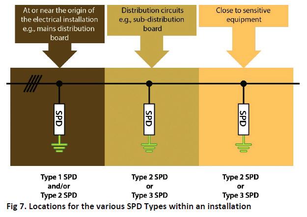






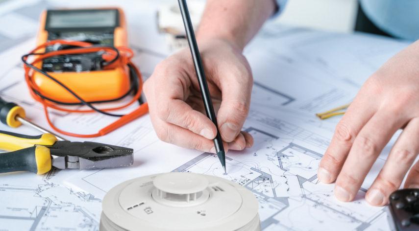
Michael Coupland of Aico offers advice to ensure you’re not caught off-guard in the future.


Even if you’re familiar with BS 7671 and the electrical wiring regulations, you might be missing a crucial detail lurking within its pages This seemingly innocuous line tucked away at the back holds major implications for electricians – and your next smoke alarm installation could depend on it.
That line simply states: “Fire detection and fire alarm systems shall comply with the relevant parts of BS 5839 series ” But what it truly means is that BS 5839:6, another British Standard specifically dealing with fire alarm systems, is inseparable from BS 7671 when it comes to smoke alarm installations Remember, the word “shall” in the appendix clarifies – complying with BS 5839:6 isn’t optional, it’s mandatory
Compliance is key
For electricians, adhering to BS 7671 is essential. It’s the foundation for maintaining your NICEIC or equivalent membership –and your good standing in the industry So, that paragraph linking BS 7671 to BS 5839:6 leaves no room for ambiguity
New smoke alarm installations or partial upgrades must meet the minimum requirements of BS 5839:6, which vary depending on the type of property:
● Rented properties: Grade D1 Category LD2 is the minimum
● Private dwellings: Grade D2 Category LD2 (new/materially altered property or
where rewire is undertaken), Grade D2 Category LD3 in existing properties.
The standard states that the level of protection for the occupants needs to be directly related to the fire risk, the categories of system describe the level of protection the systems provide:
● Category LD2: A system incorporating detectors in all circulation areas that form part of the escape routes from the premises, and in all specified rooms or areas that present a high fire risk to occupants, including any kitchen and the principal habitable room.
● Category LD3: A system incorporating detectors in all circulation areas that form part of the escape routes from the premises
Real-world example: avoiding costly oversights
Working alongside local housing providers in my area, upgrading kitchens and bathrooms, heat alarms get installed in kitchens during the upheaval – a smart move But, what about the rest of the house? If the living area isn’t equipped with a smoke alarm, the entire installation fails to comply with BS 5839:6, and consequently, BS 7671 Missing that single alarm could lead to the following:
● Rework and frustration: You might need to rip up carpets and floorboards
to install the missing alarm, adding time and complexity to the project.
● Damage and delays: Unforeseen property damage and potentially upset clients are never desired outcomes
Radio frequency: a modern solution
The good news is that Wireless Radio Frequency (RF) technology offers a convenient and flexible alternative to traditional wired systems With RF products and accessories, you can avoid the hassle of lifting floorboards and keep everything neat and tidy
Aico’s Ei3000MRF Module is part of the next generation of RF solutions, allowing for wireless interconnection and data extraction when installed into any of Aico’s 3000 Series alarms
Stay in the know, stay compliant
For electricians in England, Wales, and Northern Ireland, complying with BS 7671’s point 560 10 boils down to one thing: mastering BS 5839:6
It’s important to remember, Grade D1 Category LD2 is the minimum for rentals, and Grade D1 Category LD2 is the standard for private dwellings.
Don’t let a hidden requirement trip you up – stay informed and stay compliant

GET MORE DETAILS ABOUT AICO’S RANGE OF ALARMS AND ASSOCIATED PRODUCTS AT: WWW.RDR.LINK/EBB011
In THIS REGULAR COLUMN, DR. TOM BROOKES ANSWERS YOUR QUESTIONS RELATED TO FIRE SAFETY. THIS TIME AROUND HE LOOKS AT THE QUALIFICATION REQUIREMENTS TO ENABLE ENTRY ON TO INDUSTRY SCHEMES.
BAFE has changed the criteria for the competence of engineers for fire alarm engineers and technicians. Does that mean I must undertake the BAFE FIREQUAL qualification to be part of the SP 203-1 scheme?
There’s been quite a bit of confusion around this lately, so hopefully we can clear some of it up
BAFE obviously has its own qualification in the form of FirEquAl, and many individuals are under the assumption that they must undertake this qualification to be part of the overall BAFE scheme This isn’t the case, as it would potentially create a monopoly.
So, let’s take a look at what it says in plain English:
BAFE SP203 Required Qualifications
SP203-1 Scheme V8 started on the 1st of November 2023, which includes the requirement for engineers/technicians that the organisation employs to be competent individuals and demonstrate that all are employed.
Firstly, if you don’t have an actual fire alarm qualification in a court of law, how do you prove you’re competent? in my view, this means that everyone working on fire alarm systems must be qualified in fire alarm systems (sorry, qualified electricians, you must also have a dedicated regulated fire alarm-specific qualification on top of your other certificates)
it also states that all people must have the ability to demonstrate core knowledge of fire detection and fire
alarm system design, installation, commissioning and maintenance work (including BS 7671 iET Wiring regulations) and the ability to carry out safe isolation
BAFE SP 2303-1 V8 now states that every company must have a named and documented lead Designer, lead installer, lead Commissioner and lead Maintenance engineer These lead roles in a smaller company could all be the same person i personally would have liked to have seen the Commissioner as a different person than the installer, but that’s the route that has been taken on this occasion
The requirement for an individual to prove “they are competent” is the bit that seems open to interpretation The scheme states that the lead roles must be filled by individuals with regulated minimum level 3 qualifications in BS 5839-1 that cover design, installation, commissioning, and maintenance
So, what are your options?
Awarding body EAl offers a range of fire alarm qualifications that meet the requirements of the BAFE scheme
Zzeus Training is a dedicated fire alarm training centre and covers all the requirements needed
We were the first to offer the EAl qualifications, however some good news has arrived recently with the announcement that NiCEiC has updated its training offering and is now running


the EAl qualifications also in my opinion this will be the ‘go-to’ fire alarm qualification to meet the requirements for readers of this esteemed publication, and also give ECS card holders either a stand-alone Fire Operative Card or, if you’re a Gold Card electrician, you can have the fire alarm qualification put on the back of your card
Experienced workers, if you have a minimum of five years’ experience, we can put you through the EAl level 3 NVq at Zzeus Training
The course is portfolio-based, with an audit assessment, and looks at the experience side of fire system engineers A pass in the NVq would cover all the BAFE roles, plus enable the engineer to gain a fire gold card at the same time.
You can, of course, go down the FirEquAl route as that also meets the requirements of the scheme, so it’s good to know that individuals have plenty of options available to them

DO YOU HAVE A QUESTION YOU'D LIKE ANSWERED?
EMAIL YOUR QUERIES TO: TOM@ZZEUS.ORG.UK

GET MORE DETAILS ABOUT ZZEUS TRAINING AND THE RANGE OF COURSES ON OFFER AT: WWW.RDR.LINK/EBB012
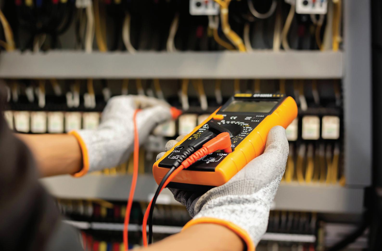
The technical team at Enkin explore single-phase and three-phase power supplies and define the key features that set the two apart.
Single-phase and three-phase power supplies each have roles that they perform best, and the two are notably quite different from one another in terms of power delivery In this article, we aim to outline their key differences, and the tasks they’re most suitable for.
What is a ‘phase’ in electricity?
A phase is a current within a wire that produces electrical signals in a waveform
This waveform is visible via an oscilloscope, and a phase can be determined by the unit type by knowing the load that they distribute
In a single-phase power supply, there are two wires: one power (phase) wire that delivers the current, and one neutral wire
The neutral wire isn’t considered a phase wire as it carries current back from the load to the source
During the phase cycle, power delivery fluctuates in voltage, and the power wave peaks at 90 and 270 degrees This means that power delivery is at maximum at two points during the power delivery cycle, and dips at other times to less than optimum
Single-phase is primarily used for domestic properties, being more suitable for lighting, sockets, and switches, however, a three-phase supply may be required for greater loads. Three-phase systems can also be converted to three
single-phase supplies and doing this will allow an even spread of the load across the three phases
A three-phase system consists of three power wires, arranged to be out of phase with one another by 120 degrees. This means that all three phases of power have entered the cycle by 120 degrees, and all three phases peak at different times during a complete cycle This creates waveforms with no peaks or drop-offs, resulting in a much smoother and more consistent power supply when compared with single-phase power
Not only does this mean they’re far more efficient at power distribution over long distances, but three-phase power also has a much higher power capacity than its single-phase counterpart, making it a great application in commercial and industrial settings
Loads in a three-phase system should be balanced to ensure even power distribution across all phases A balanced load minimises the risk of voltage fluctuations, ensuring the system operates efficiently.
The two most common configurations of three-phase systems are known as Delta and Wye Both have the capability to deliver power over three wires, however the differences between the two are based on the number of wires available, as well as the current. The
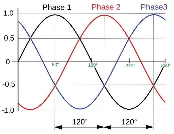
Delta connection has only three wires, whereas the Wye configuration carries a neutral wire that allows both single-phase and three-phase connections.
Single-phase vs three-phase power
It’s important to note the voltage difference between single- and three-phase supplies When using a single-phase supply, the voltage is limited to 230 V AC
However, when three-phase is being used you may find up to 400 V between phases This is due to the power transfer in three-phase being almost double that of a single-phase supply
As a by-product of this, a three-phase power supply is vastly more efficient, able to transmit three times the power that a single-phase supply is capable of, while needing only two more wires

BROWSE ENKIN’S RANGE OF DIMMING PRODUCTS AND GET MORE TECHNICAL SUPPORT
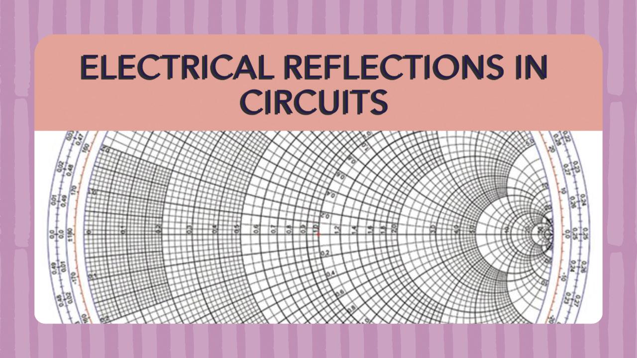
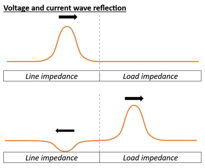
John
In this article, I’m looking to challenge your grasp of electromagnetism and explore the intricate realm of electrical reflections in circuits
This guide aims to provide an introduction to the subject, with a special emphasis on incorporating the Smith Chart, and its significance in the day-to-day work of electrical engineers.
Impedance, measuring how much a medium opposes the flow of electrical current, is a fundamental factor influencing electrical reflections
In circuits, the reflection coefficient (Γ) quantifies the amount of reflection at the interface between the conductor and the surrounding medium
The Smith Chart, a graphical tool extensively used in electrical engineering, aids in visualising and solving problems related to impedance matching, making it a valuable asset when dealing with electrical reflections
to visualise impedance changes and address problems related to signal quality effectively
3. Power distribution systems
Maintaining the integrity of power distribution systems is vital Electrical engineers should utilise the Smith Chart in addressing reflections to prevent issues such as power loss and inefficiencies in electrical networks
Conclusion
c i r c u i t s , t h e i
s u r r o u n d i n g m e d i u m
This reflected wave interferes with the incident wave, creating a standing wave pattern along the transmission line. This standing wave pattern manifests as variations in voltage and current along the line, creating regions of higher and lower amplitude These variations are often referred to as voltage and current ripples
Understanding impedance, reflection coefficient and the Smith Chart
There are some practical implications for electrical engineers to consider:
1. Circuit design
Electrical engineers engaged in power transmission must incorporate the Smith Chart to comprehend impedance variations, optimising power transfer between different components to ensure minimal power loss and interference
2. Troubleshooting
Identifying and managing reflections is crucial for troubleshooting circuit issues. Engineers can leverage the Smith Chart
A robust understanding of electrical reflections in circuits, coupled with the effective use of the Smith Chart, is indispensable for electrical engineers and tutors alike
By comprehending the principles behind impedance, and reflection coefficients, and utilising the Smith Chart, professionals in the field can design more efficient systems, troubleshoot circuit issues effectively, and contribute to the advancement of electrical engineering
Incorporating this knowledge into everyday practices, alongside the use of the Smith Chart, will undoubtedly enhance the skills and expertise of electrical engineers.


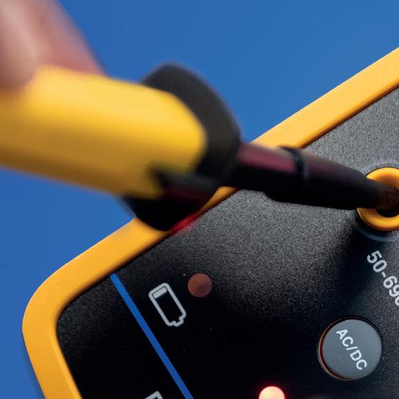


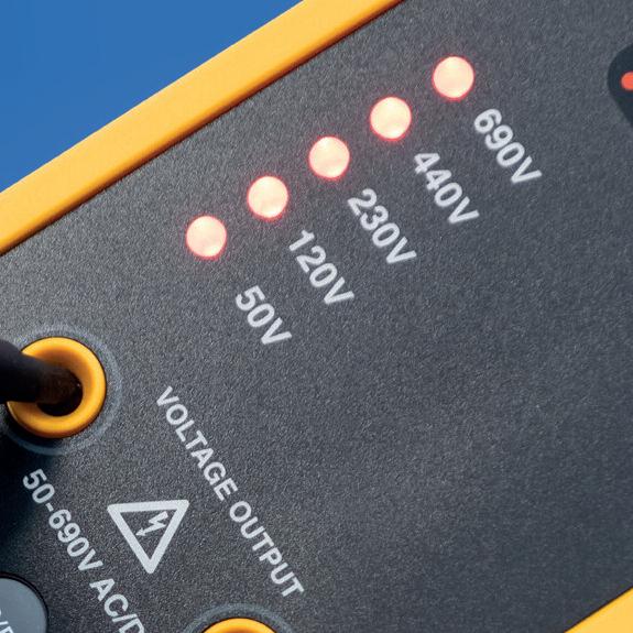













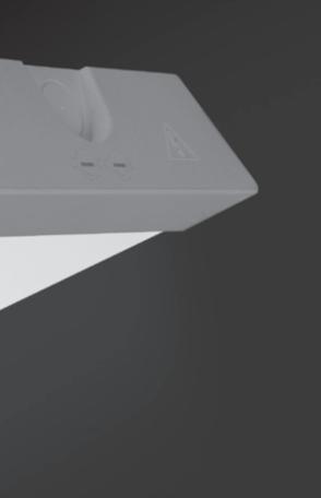





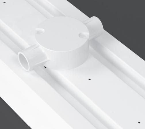


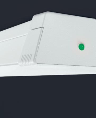


With the continuing rise in energy costs, consumers are looking at ways to mitigate against rising bills and recoup some benefits through renewable technologies.
Solar PV systems have been on the market for many years with homes fitted with Solar PV benefiting from a fairly generous feed in tariff (FIT) However, this scheme was closed to new applications on 1st April 2019 It was not until 1st January 2020 that the government introduced the Smart Export Guarantee (SEG)
The SEG tariffs still allow customers to receive payments for electricity generated and exported back to the grid, but the rates are much lower and vary between energy suppliers
So, if homeowners with Solar PV systems are not receiving the historic financial benefits, what is the alternative?
Electrical Energy Storage Systems (EESS), also known as battery storage, offer an attractive alternative Instead of
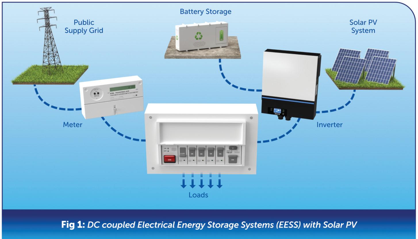
exporting back to the grid, the energy generated from Solar PV can be stored in the EESS and used in the home at certain times of the day, as shown in Fig 1.
Can an EESS System be installed without Solar PV?
There’s a common misconception that an EESS can only be installed when combined
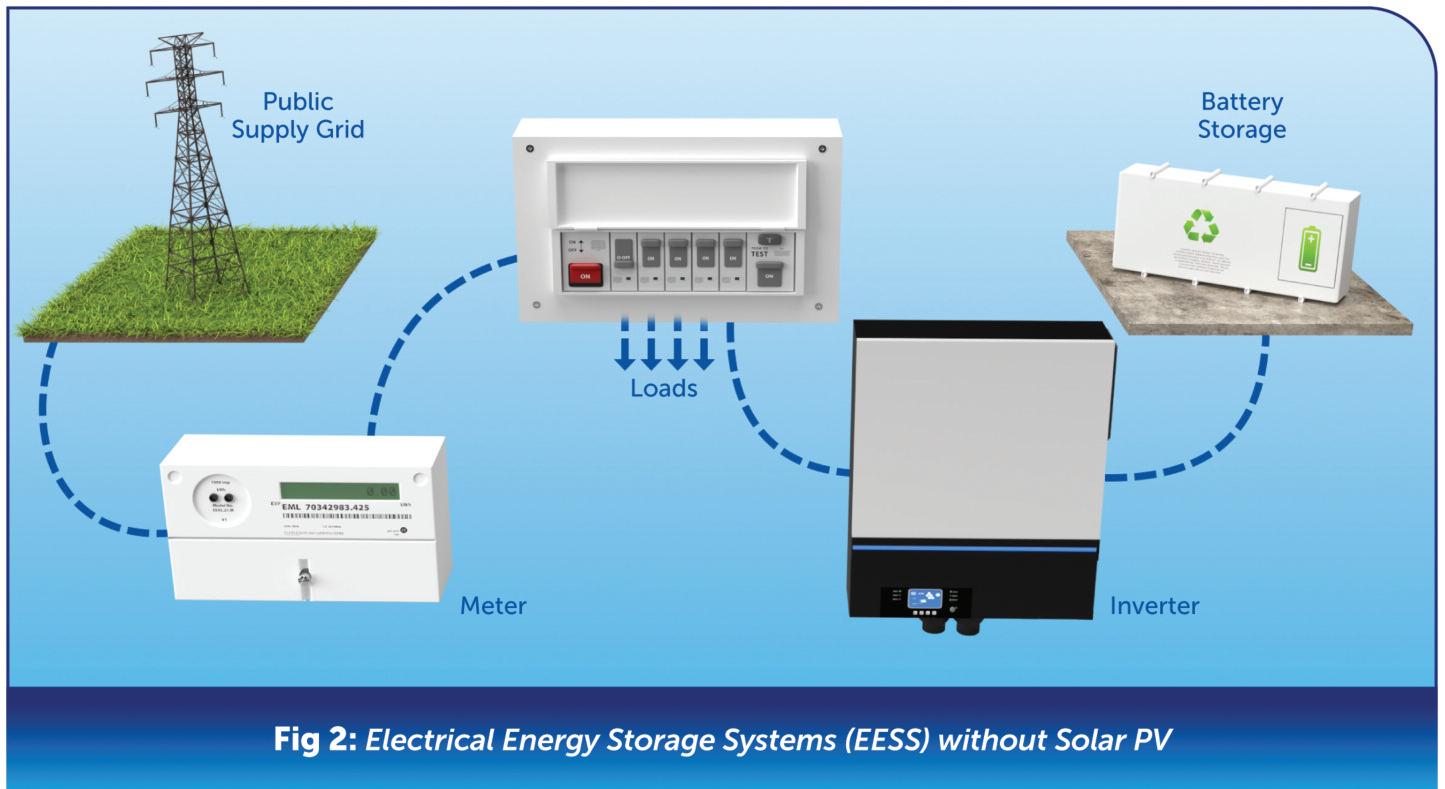
with a Solar PV system Whilst it’s true that combining these renewable technologies would be the most cost-effective way over time, that doesn’t mean that an EESS can’t be installed on its own
A few energy suppliers are now offering time-of-use electricity tariffs This is where homeowners purchase electricity from the grid to charge the battery when

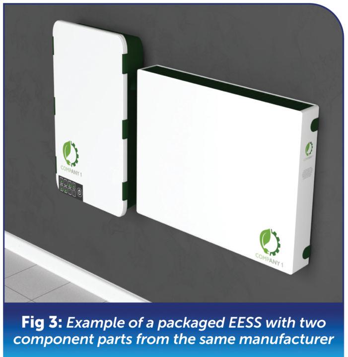
the prices are cheaper and then use it in the home at peak times to avoid buying it from the grid, see Fig 2
The main question that gets asked by homeowners when they’re thinking of installing renewable technologies is: “what’s the payback period?”
While the costs of installing Solar PV and EESS are becoming increasing affordable due to increased demand, it’s worth pointing out that there can still be a considerable up-front investment for the installation of these systems
The payback period depends on various factors such as the size and type of the system In the UK, the average payback time for a domestic EESS is around 10-12 years (source: Electrify Wales/Solar & Battery Payback/28 April 2023). Installing an EESS offers many additional benefits, including:
● Off-grid independence,
● Lower energy bills,
● Low maintenance,
● A greener environment.
The wide range of manufacturers and equipment available can provide a minefield of choices when deciding which system to install.
All installed systems should be carefully designed beforehand to meet the requirements of the individual customer and installed in accordance with current regulations and standards
In general, Electrical Energy Storage Systems come in two types – packaged or discrete component.
Packaged systems are complete solutions available commercially as an off-the-shelf product They could have all the component parts in one single enclosure or comprise of separate components all from the same manufacturer
The potential benefit of this type of EESS is that the manufacturer is responsible for all its component parts, its safety and its stated performance, as shown in Fig 3
Discrete component systems are assembled from two or more discrete component parts, perhaps from different manufacturers
This does provide a wider range of choice and can make the installation more bespoke to the customer’s needs (see Fig 4). However, a bespoke system
“The main question that gets asked by homeowners when they’re thinking of installing renewable technologies is: “what’s the payback period?”
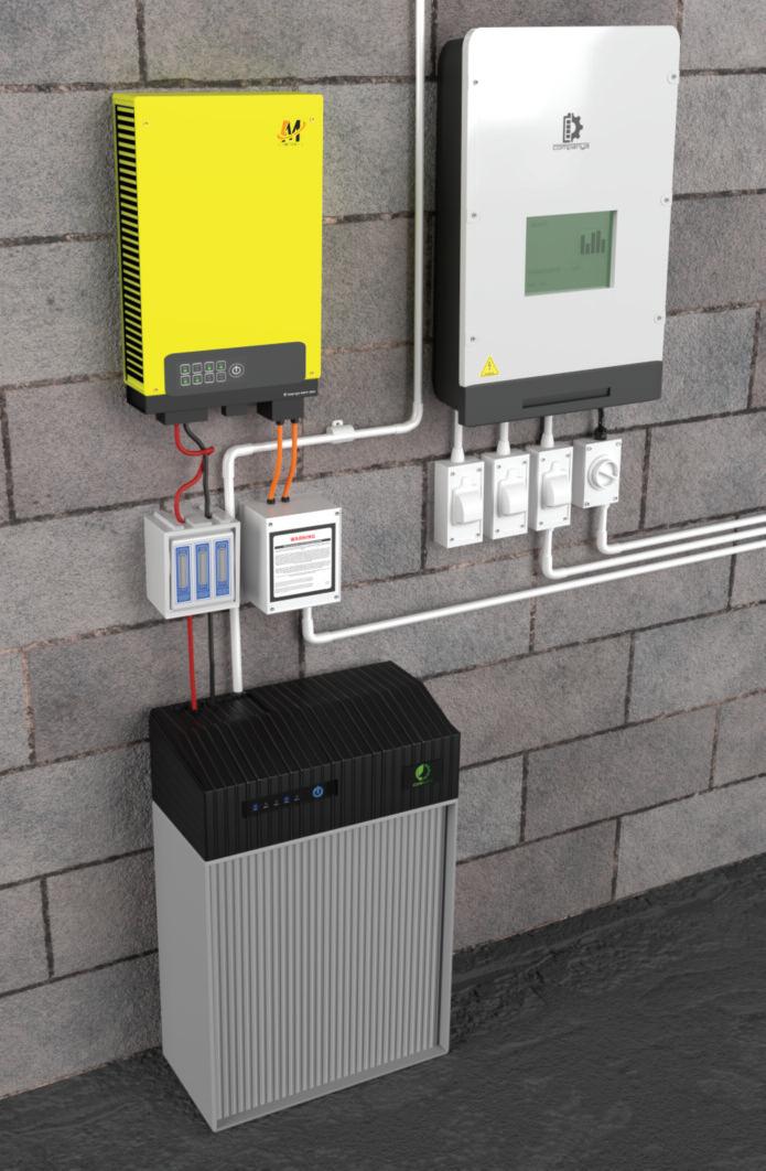
creates a greater reliance on the designer and installer to ensure safety and compatibility between components
All electrical installations need to be designed and constructed to meet the safety requirements of the Electricity at Work Regulations 1989 (EAWR).
To meet the statutory requirements of the EAWR, designers and installers need to refer to BS 7671 and other documents, such as:
● The IET Code of Practice for Electrical Energy Storage Systems, ● MCS Standards Document MIS 3012: The Battery Standard,
● ENA Engineering Recommendations G98, G99 and G100
BS 7671 contains specific information concerning battery installations in Section 551 and Chapter 82 These guidance documents are displayed in Fig 5
It is of the upmost importance that designers and installers comply with these regulations, standards and guidance documents. The manufacturers’ instructions shall also be taken into account in addition to the requirements of BS 7671
This will ensure that the correct equipment and installation methods are used for safe operation, use and maintenance of the EESS.
As with Solar PV installations, Electrical Energy Storage Systems are notifiable to the Distribution Network Operator (DNO) This is because these systems work in parallel with the grid supply and have the potential to feed energy back into the grid The notification process is published by the Energy Networks Association (ENA) and follows Engineering Recommendations G98, G99 and G100
G98: Single Premises
This process is very straightforward and uses a ‘fit and inform’ procedure
The DNO notification is required within 28 days after the installation has occurred To follow the recommendations for a simple G98 fit and inform process, the EESS installation shall:
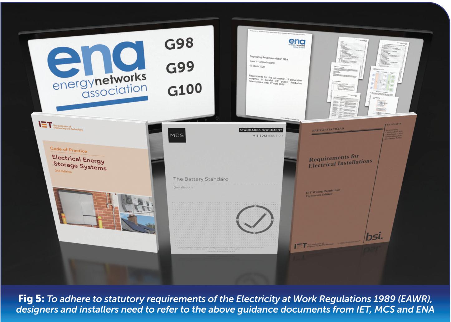
● Have a total site generation/inverter capacity of less than or equal to 16 A per phase,
● Be a single installation on a single property,
● Use a G98 type tested approved inverter
G98: Multiple Premises
This process requires DNO approval before the installation proceeds This is due to the potentially larger impact on the electricity network with multiple systems within a close geographical proximity T
D
● Have a total site generation/inverter capacity of less than or equal to 16 A per phase,
● Use a G98 type tested approved inverter
G99: Installations
Systems over 16 A per phase will generally fall into the G99 procedure and will vary depending on the size and type of system The three routes are:
G99 Fast Track (Route 1)
The fast track process is to provide a simplified connection process for a small scale EESS that is being installed
in addition to existing local generation such as an existing domestic Solar PV system
G99 Standard (Route 2)
This process is for an EESS with type A generators less than or equal to 16 A per phase and a total generation of less than or equal to 32 A per phase In addition, only type tested inverters are used
G99 Full (Route 3)
This process is for all other systems This will include type A generators rated over 16 A per phase and all other type B, C and D generators
The standard and full G99 process requires a written connection application and a formal DNO approval prior to proceeding with the installation.
A G99 commissioning form is to be supplied to the DNO within 28 days or alternatively could be witnessed by the DNO if requested
This scheme measures and controls the amount of power from generation systems that are to be exported to the grid This can be achieved by restricting the generation output and/or by balancing the customer’s demand This is done to prevent the agreed export capacity being exceeded.
“Electrical Energy Storage Systems provide a good option for consumers to make the transition to prosumers, consumers and producers of electrical energy.”
Electrical Energy Storage Systems provide a good option for consumers to make the transition to prosumers, consumers and producers of electrical energy This gives the customer greater flexibility in how they use and pay for their energy.
When combined with a Solar PV system, an EESS allows for greater grid independence and contributes to a carbon neutral future for the UK
Technology and innovation within renewable systems is improving all the time and this will make their design and installation more accessible
This is an exciting time in the renewables world and could create a great opportunity for electricians to get involved in designing, installing and commissioning Electrical Energy Storage Systems.



In this article, originally written for the IET Wiring Matters publication, James Eade looks to dispel some of the myths surrounding the use of flexible cables in fixed installations.
The content for this piece was inspired by a comment that was posted on the IET EngX Forum which stated: ‘Flexible cables are not permitted in fixed installations’. This myth is not uncommon
The origins of it are unclear but seem to date back to the 15th Edition of the IEE Wiring Regulations (if not before) and are believed to have stemmed from the types of insulation materials used for flexible cables in years gone by.
In the 16th Edition, there were definitions for flexible cables (for example, a cable designed to be flexed in use) and flexible cords (a flexible cable with conductor cross-sectional areas (csa) of 4 mm2 or less), but no reference to them being specifically prohibited
Like phase separation, the memories of some old requirements linger on In the 16th Edition (including AM2, 2004), Regulation 521-01-04 did state that:
“A flexible cable or flexible cord shall be used for fixed wiring only where the relevant
521.9 Use of flexible cables
521 9 1 A flexible cable shall be used for fixed wiring only where the relevant provisions of BS 7671 are met. Flexible
cables used for fixed wiring shall be of the heavy duty type unless the risk of damage during installation and service, due to impact or other mechanical stresses, is low or has been minimized or protection against mechanical damage is provided
NOTE: Descriptions of light, ordinary and heavy duty types are given in BS EN 50565-1.
Continuing with the current edition, Regulations 521 9 2 and 521 9 3 go on to require flexes to be used for connecting equipment that may be moved during use. The definition of flexible cords has also gone, leaving just flexible cables listed in Part 2 However, there is still no prohibition on their use
The main differences between cables used for installations and flexible cables are the use of Class 5 finely stranded conductors rather than Class 1 (solid) or Class 2 (semi-stranded), coupled with differences in insulation materials to allow for the flexibility
Such cables are in widespread use from construction sites to events (where they are used almost exclusively), as well, of course, as final connections in installations for lighting fixtures or from fused connection units to equipment such as heaters, for example
Having decided to wire your installation in flexible cable, what are the "relevant provisions of BS 7671" alluded to in 521.9.1? As well as complying with the general rules, there are a couple of key points to note with this:
● The flexible cable should have appropriate mechanical robustness for the application as described in the note to the Regulation which refers to BS EN 50565-1 This Standard describes various categories, summarised thus:
1. “Heavy duty” describes the stresses that might be expected in, for example, industrial and agricultural premises
2. “Ordinary duty” describes the stresses that might be expected in, for example, domestic, commercial and light industrial applications.
3. “Light duty” applications might include flexible cables for small appliances.
4 “Extra light duty” applications are, for example, very small appliances such as electric shavers, chargers for mobile phones, etc Where this protection cannot be achieved using the cable alone, suitable additional mechanical protection should be provided
● The temperature rating of the flexible cable should be suitable for the connected wiring accessories (Regulation 526.4).
● Wiring terminations may need to be finished in an appropriate termination as required of Regulation Group 526 9 IET Guidance Note 3 has details on appropriate wiring accessory terminals and their markings in Table 2.1.
● Generally, all the current-carrying capacity and voltage drop tables in Appendix 4 are for Class 1 and Class 2 stranding, with the exception of Tables 4F1 to 4F3 The current carrying capacity and voltage drop may need to be corrected if using tables for other cables, such as PVC cables complying with the insulation and temperature requirements of Table 4D2 Information is given in Section 2 4 of Appendix 4
Far from being prohibited, flexible cables are required in some parts of BS 7671:2018+A2:2022 and examples include:
● Regulation 422 3 201 permits their use for locations where a particular risk of fire exists, although has some requirements for their construction or protection as detailed in Regulation Group 521 9
● Regulation 413.3.4 has a particular requirement concerning their use in parts of the installation with protective measure double or reinforced insulation
● Regulation 418 3 6 for electrical separation to more than one item of equipment requires flexible cables to incorporate a protective conductor.
● They are required to be used for suspended current-using equipment (Regulation 522.7.2).
● They are required in installations in flexible structures, or where structures are intended to be moved (Regulation 522 15 2)
● There are minimum cross-sectional areas for flexible cables "for any other application" in Table 52 3
● Flexible cables are required for the connection of equipment that may be regularly or occasionally moved in use (Regulations 521.9.2 and 521.9.3).
● Flexible cables are required as a method of connection of equipment having a high protective conductor current as detailed in Regulation 543 7 1 202
● Some Part 7 special locations specify certain wiring systems for which flexible cables are options, or mandated as noted in Regulation 522 15 2: (Regulation Group 704 522 8, Regulation 711.52, Regulation 717 411 3 1 2, Regulation Group 717 52, Regulation 721 521 2, Regulation 740 521 1, Regulation 740 55 1 1)
As ever, it is worth reviewing the fundamental principles in Part 1 Of relevance here are Regulations 132 6 and 132 7 for the cross-sectional area of conductors and types of wiring and installation methods, plus Regulation Group 133 for the selection of equipment. Flexible cables can tick all the boxes and, if the extra cost over more rigid types is not a concern, there is no reason why they can’t be used
With thanks to Graham Kenyon for his contributions to this article, originally published in May 2023 for IET Wiring Matters

BROWSE OR DOWNLOAD A DIGITAL COPY OF THE IET WIRING MATTERS 2024 ANNUAL AT:

Versatile Lighting:
Coverage for any task, ensuring no area is left in the dark.
Designed to Last the task:
Extended working times at maximum output without compromising battery life.
Hands-Free Operation:
Convenient hands-free operation with a variety of versatile mounting options.
Durable and Hardwearing:
Built from robust materials and IP-rated to withstand the toughest work environments.
Darren Crannis, ECA Technical Manager, looks at protective earthing systems and unravels the difference between PME and PNB.
The distinctions between TN-C-S earthing variants, Protective Multiple Earthing (PME) and Protective Neutral Bonding (PNB), often lead to confusion
Despite both falling under the TN-C-S category, they diverge significantly, impacting design considerations and inspection outcomes
Here we aim to shed light on the distinction between PNB and PME, providing guidance for professionals
The basics of TN-C-S
A TN-C-S earthing system, denoted by its single source of supply, establishes a direct connection with Earth at one or more points The 'T' signifies this connection, while 'N' designates the connection of exposed conductive parts to Earth through a protective conductor
The subsequent 'C-S' letters imply the combination of neutral and protective conductors in the supply, which then separate within the installation This configuration, also known as PME, involves the earthed Protective Earth Neutral (PEN) conductor, forming the backbone of the system
PME: a closer look
TN-C-S transforms into PME when the PEN or Combined Neutral Earth (CNE) conductor is earthed at multiple points in the supply and at the source itself This ensures a low impedance path to Earth for all elements of the PEN conductor, making it the most prevalent form of
connection to installations
In practical terms, all exposed-conductive-parts link to the PEN conductor via the main earthing terminal, creating a network of interconnected terminals
PNB: a useful alternative
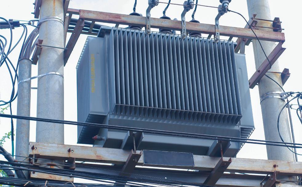
Protective Neutral Bonding (PNB), akin to PME, operates within the TN-C-S framework but introduces a crucial distinction
In PNB, the neutral earth connection is established once at or near to the customer's installation, rather than at multiple locations This is particularly common in scenarios where dedicated transformers for individual customer connections or pole-mounted transformers serving isolated locations are prime examples of TN-C-S PNB setups
TN-C-S PNB surfaces when the consumer's installation is tethered to a single source of supply at just one point on the network This often involves a direct supply to an individual customer directly from the transformer
Engineering Recommendation G12/4 from the Energy Networks Association advises that the connection to Earth and the consumer's intake should ideally be 40 meters or less apart Minimising the risk of voltage rise due to a broken neutral is crucial, prompting the recommendation to make this connection as close as possible to the consumer's supply terminals.
When dealing with TN-C-S PNB installations, it's crucial to acknowledge that, in most cases, they can be considered equivalent to TN-S for sizing the main earthing and main protective bonding conductors The maximum size of the main protective bonding conductor need not exceed 25 mm² of copper conductor.
In contrast, TN-C-S PME installations are treated akin to where PME conditions apply, where the maximum size of the main protective bonding conductor should not surpass 50 mm² of copper conductor
Designers are advised, per Note above Table 54.8 of BS 7671:2018+A2:2022, to confirm any specific requirements of the local Distribution Network Operator (DNO) DNOs may necessitate a larger size of protective bonding conductor to accommodate local network conditions
In the realm of TN-C-S earthing arrangements, understanding the subtleties between PME and PNB is paramount This knowledge not only streamlines design processes but also ensures compliance with regulations, minimising the risk of 'unsatisfactory' inspection reports.

BS 7671 contains clear requirements in respect of the order in which many tests have to be carried out during initial verification. However, no such information is given in respect of testing carried out as part of a periodic inspection of a property. This article discusses some differences between initial and periodic verification pertinent to testing and suggests a sequence of testing which may be appropriate for use when carrying out a periodic inspection.
Initial verification
Section 643 of BS 7671 contains requirements for the testing of an electrical installation during initial verification
Regulation 643 1 states that the tests described in Regulations 643 2 to 643 11, where relevant and appropriate for the installation being tested, shall be carried out. It also states that the tests described in Regulations:
● 643 2 Continuity of conductors
● 643 3 Insulation resistance
● 643 4 Protection by SELV, PELV or by electrical separation
● 643.5 Insulation resistance / impedance of floors and walls
● 643 6 Polarity
shall be undertaken, where relevant, in that sequence before the installation or that part being worked on is energised.
It is important that these tests are performed in the correct sequence
For example, we must verify the continuity of a conductor before carrying out an insulation resistance test to confirm that the test voltage is
applied to the full length of all of the relevant conductor(s) to be tested
Without verifying end-to-end continuity first the insulation resistance test might only be applied to a part of the conductor(s)
Regulation 643 1 advises that: ‘If any test indicates a failure to comply, that test and any preceding test, the results of which may have been influenced by the fault indicated, shall be repeated after the fault has been rectified’ Additionally, where the installation incorporates an earth electrode, the testing described in Regulation
“This preliminary testing might identify damage, defects or non-compliances which render the installation dangerous and which may prevent, or severely limit, any further testing activities.”
643 7 2 shall also be carried out prior to the installation, or that part being worked on, being energised.
Thereafter, the applicable tests described in Regulations:
● 643 7 3 Earth fault loop impedance and prospective fault current
● 643.8 Additional protection
● 643 9 Check of phase sequence
● 643 10 Functional testing
shall also be carried out
Periodic verification
BS 7671 does not state a sequence for testing forming part of periodic inspection activities It also does not state which tests should be carried out during periodic inspection and testing
However Regulation 651 2 states that the periodic inspection shall be supplemented by appropriate testing and measurements from Chapter 64
Any sequence of testing employed during a periodic inspection must take account of the differences between initial and periodic verification
Perhaps the key difference is that, in many cases, an existing installation will be
connected to a supply and will be energised prior to the periodic inspection taking place. Where this is the case, it would seem wise to carry out some testing at the origin, with the installation energised, to determine the adequacy, or otherwise, of the supply arrangement before progressing to any further inspection or testing within the installation This preliminary testing might identify damage, defects or non-compliances which render the installation immediately or potentially dangerous and which may prevent, or severely limit, any further testing activities For example, incorrect polarity of the incoming supply, or inadequacies in the earthing arrangement for the installation
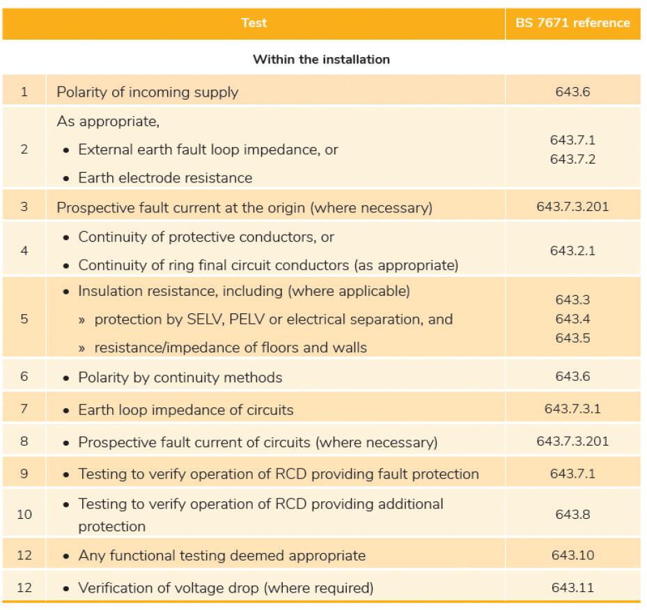
The sequence shown in Table 1, reproduced from the NICEIC publication Site Guide (18th Edition AMD2), may be appropriate, bearing in mind that not all the tests listed will be applicable to any particular installation
BS 7671 does not state a specific sequence for testing during a periodic inspection. As, in many cases, the electrical supply to the premises being inspected will be energised, once it has been established via a visual inspection of the relevant equipment etc. that it is safe to do so, the suitability of the existing supply arrangement should be verified as a first step
In some cases, where issues are observed, this may well prevent any further live testing taking place or possibly stop the verification completely



ALISTAIR RIGBY: THERE WAS NO POWER TO MY NEW BOARD SO I OPENED UP THE ISOLATOR FOR A LOOK AND FOUND THIS –THE LINE WAS BARELY HELD BY ONE SCREW AND BOTH SCREWS MISSED THE NEUTRAL! I’M GUESSING THE ‘ME TER MONKEYS’ HAVE BEEN AT IT AGAIN?
When carr ying out any alterations, additions or modifications to an electrical installation it ’s essential to confirm that the incoming supply is adequate for the proposed works
During the process of installing the new consumer unit the request to have a double -pole isolator to allow safe work ing was the correct way to proceed and to allow safe work ing.
As electrical contractors, we’re reliant on third-par ties to provide this ser vice as we’re not permitted to remove the ser vice cut- out fuse or remove terminals of the metering arrangements.
We would expect that the work carried out on providing the double -pole isolator would be compliant and suitable for connection
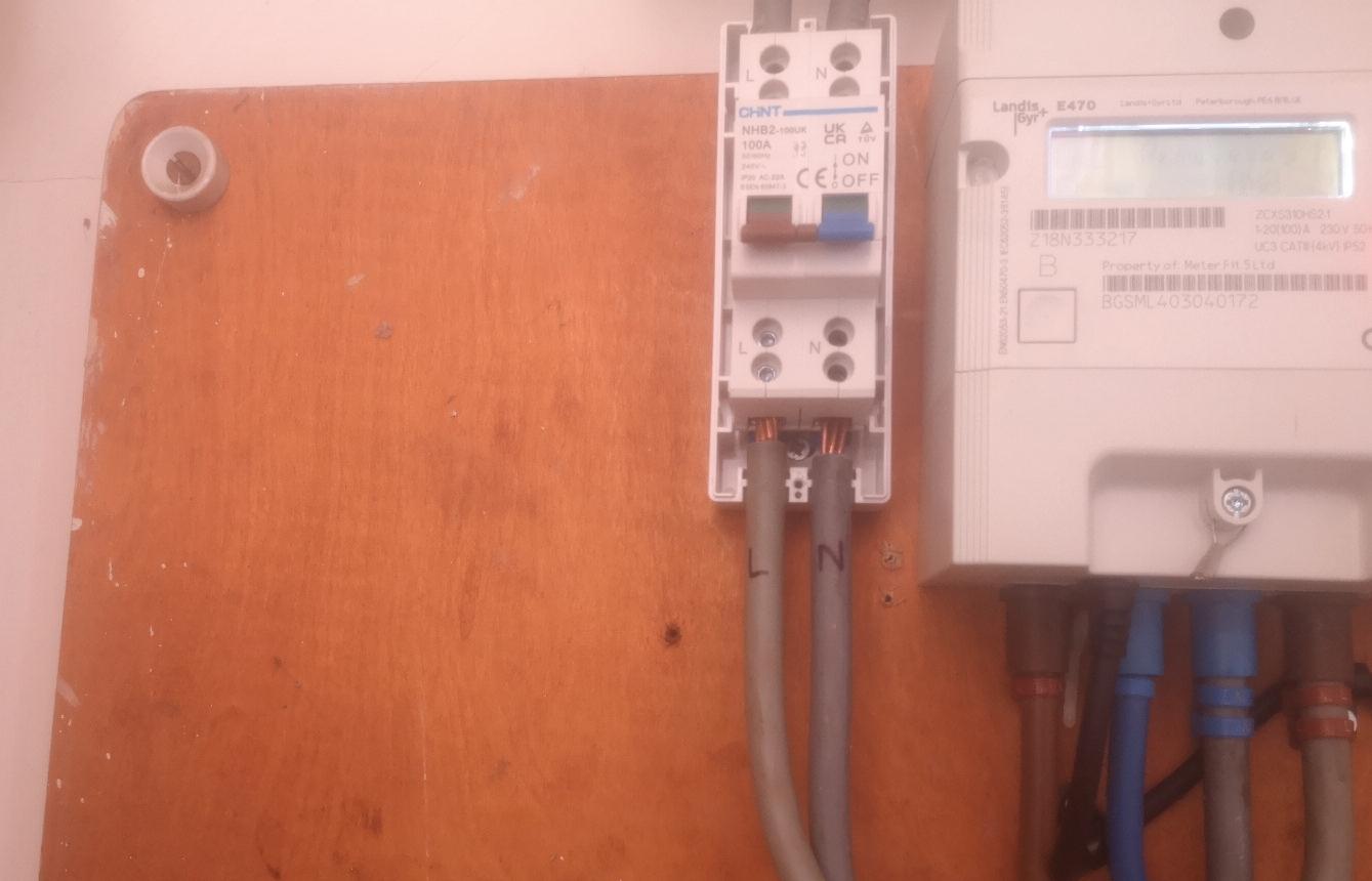
The meter tails have not been provided with a means of preventing strain on the terminations and have not been provided with secure connections at the terminals of the double -pole isolator
The supply side of the double -pole isolator has not been provided with a seal to prevent unauthorised access and the missing and loose


terminal screws do not provide adequate connections, resulting in the loss of supply to the installation
Although this would not strictly fall under the terms of an EICR, and therefore would not be subject to a classification code, the infringements can still be listed
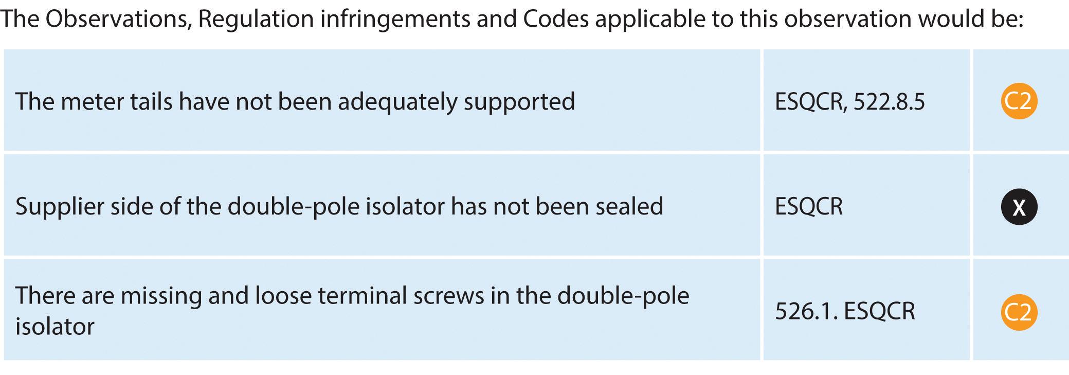

Updated for BS 7671:2018+A2:2022, NAPIT ’s EICR Codebreakers publication is purpose -written to aid contractors, inspectors and clients, and now includes updates to align with Amendment 2 of the IE T 18th Edition Wiring Regulations The book is the per fect technical aid for electrical professionals and their customers.


Need help with cracking those all-impor tant EICR codes? Ever y month the technical team at NAPIT will be studying your latest ‘Caught on Camera’ photos and offering advice on the next steps, should you find a similar installation. If you want the team at NAPIT to help crack your codes then send your pic tures through to us at: pe@hamer ville.co.uk


DANIEL KENNY: I CAME ACROSS THE PIC TURED ITEM WHEN CARRYING OUT AN EICR – CLEARLY A C2 (ACCORDING TO MY ASSESSOR AND THE BIG BROWN BOOK)! NEEDLESS TO SAY, THE RODENT WASN'T TRAINED IN CLASSICAL MUSIC BUT DID A VERY GOOD JOB AT BEING THE CONDUC TOR!
I t ’s not surprising that we encounter rodents interacting with electrical installations although it ’s more often cable damage and subsequent faults that are then discovered.
One of the first things we need to consider before removing the dead mouse is whether we can we safely isolate the supply to commence work, as the timorous beastie is conducting across the incoming terminals Hopefully there’s a double -pole isolator but, if not, it may require a call to the safe isolation provider to safely remove the cut- out fuse.
Expired vermin can pose a serious health risk, as they can carr y a variety of diseases and parasites As such, we have to consider the health and safety risks to ourselves, to the client and any other par ty Never just remove the poor unfor tunate by bare hands, use disposable gloves and a filter mask instead
Have a sealable bag ready to enclose the vermin and then dispose in a general rubbish bin or inform the client to ask the local authority to collect the deceased.
This situation may require the replacement of the internal components, main switch and circuit-breakers, depending on contamination and whether there has been damage to the devices from any fault currents.
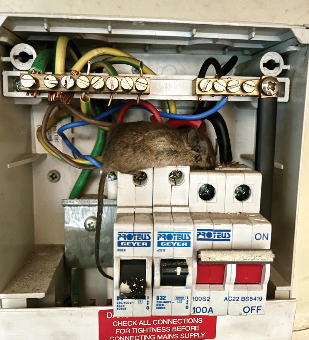


Assessment of the environment would have to be considered if vermin were likely to return (quite possibly relatives of the poor creature), so this may involve increasing the IP rating for the consumer unit to restrict access ORDER YOUR COPY
The A2:2022 18th Edition Codebreakers publication is priced at £22.00 (members) and £24.00 (non-members). It is available in both hard copy and digital versions * Price is VAT exempt and excludes postage and packaging.





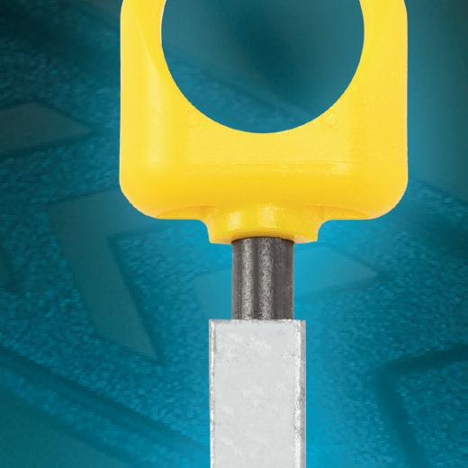
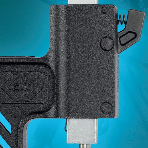















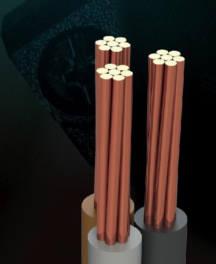







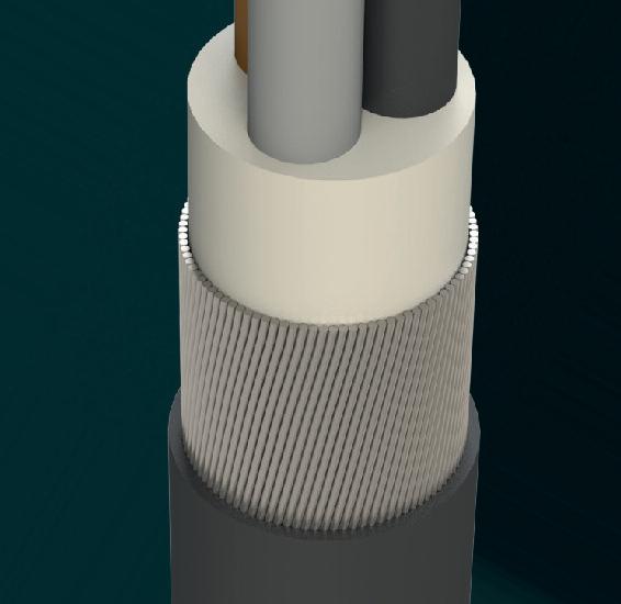

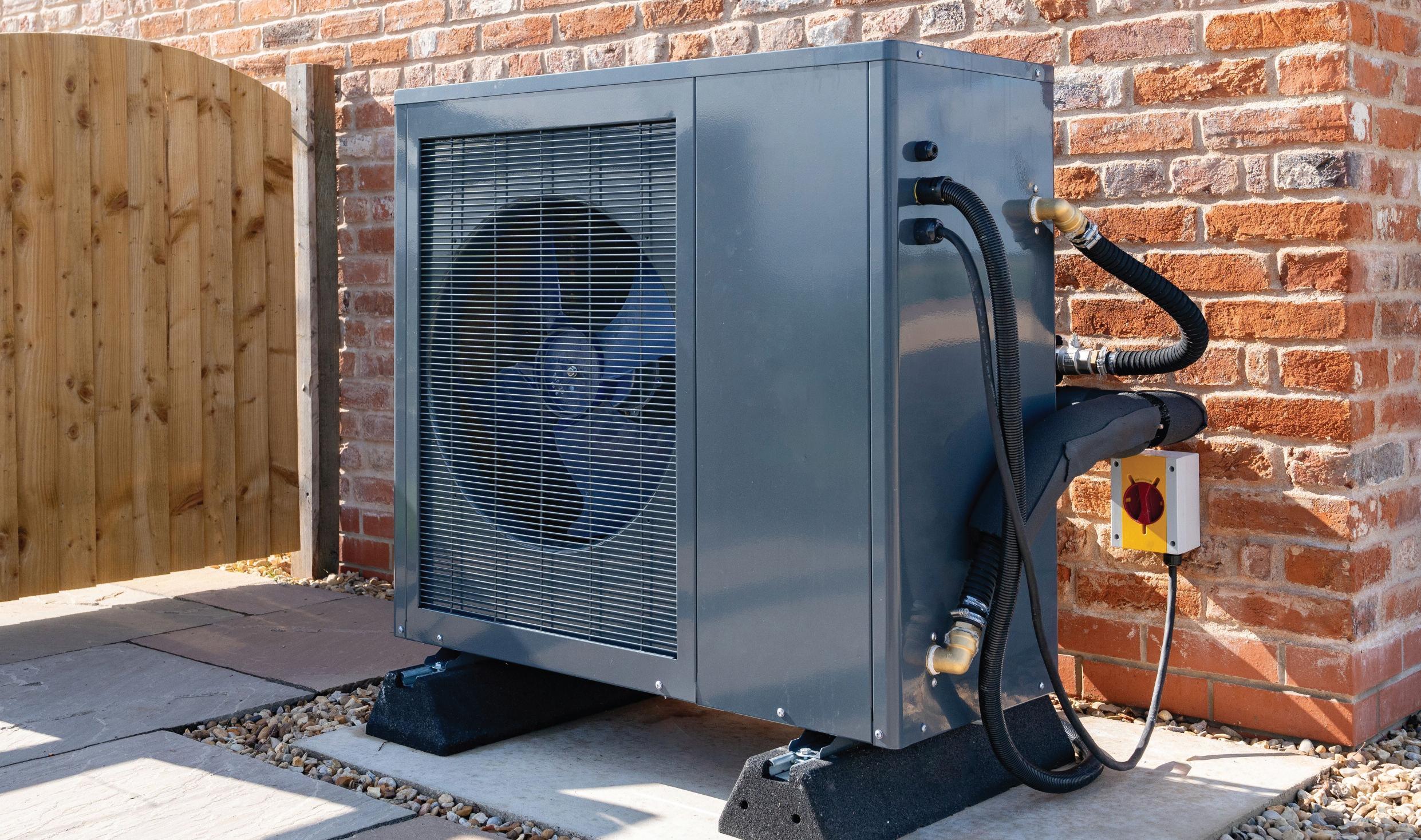
Are you involved directly with heat pump installations or expecting to deal with an existing installation? A better understanding of RCD requirements associated with HPs can save time and money for you and your customers, as Chaz Andrews, Technical Manager at Doepke UK, explains.
ASHPs (air source heat pumps) contain large inverters in comparison to domestic washing machines, for example Inverter based speed control is central to the economic performance of HP compressors and fans Inverters also help to reduce compressor starting current peaks, enabling the use of higher kW ratings on single phase supplies, relevant to 90% of UK domestic properties
In installations requiring RCD protection, HPs must be used with specific types of RCD HP inverters are not suitable for connection to Type A RCDs Examples of problems associated with incorrect RCD selection are covered in this article. Aside
from being dangerous, HPs that are paired with an unsuitable RCD also lead to the risk of an unreliable heating installation and HP damage.
Guidance
*Note: HP designs and supply rating (kW) vary significantly, even between models
from the same manufacturer Some HP designs, due to their operational leakage current, are not suitable for use with 30 mA RCDs. Check with the HP manufacturer first
The location, external ground mounted and the large exposed conductive part associated with the metal casing, pose an elevated risk in the event of a fault and inappropriate ADS (Reg 411) selection, design and installation
Where fault disconnection within the required time relies on the operation of an upstream RCD, using the incorrect ‘Type’ of RCD in association with a heat pump leads to the risk of RCD ‘blinding’. The RCD cannot reliably detect fault
currents as required by BS 7671, increasing the risk of a fatal accident.
The HP company (equipment specifier) and the installer (electrical) are reliant on each other This relates to “the duty of care owed to the consumer,” with regard to the combined safety of the equipment and the installation.
HP equipment design characteristics
In installations requiring RCD protection, the characteristics of the inbuilt inverter equipment determine the sensitivity and Type of RCD to be installed up-stream HP inverters produce AC leakage currents with frequency components above and below 50 Hz, resulting in composite (mixed frequency) residual currents, requiring the application of Type F and B RCDs (see 531 3 3 (ii) & (iii))
Type A RCDs are designed for operation with sinusoidal or pulsed residual current generated at 50 Hz – Ref 531 3 3 (i) Type A RCDs are not suitable for applications associated with inverters producing composite residual currents, such as those produced by modern HPs
For those involved in HP design and associated standards committees, see BS EN IEC 62477 H 3: Fault current waveforms produced by speed control inverter topology and the RCD type This is explained briefly below and relates to the fault currents generated at frequencies less than or greater than 50 Hz under foreseeable fault conditions.
Unwanted tripping of an RCD associated with a HP installation can be the first indication that the incorrect Type of RCD has been installed upstream Using Type A RCDs outside of the design scope (ref 133 1 3) could result in the device failing to trip when required, or unwanted tripping
In addition, transients associated with powering up and/or powering down the inverter, can exceed the transient switch-on limit for Type A RCDs, again resulting in unwanted tripping.
*Note: Before carrying out any electrical tests, check the HP manufacturer’s restart procedure Reconnecting the supply to a HP and running immediately after extended loss of supply can result in serious damage to the compressor
Can you use Type F with single phase HP?
The characteristics of the HP inverter, and the location of the fault within the equipment, determine the characteristics of the residual current
The selection of the Type of RCD must consider the fault current scenarios identified in the standards and by the HP manufacturer, in their design risk assessment documentation
Electrical installers do not have access to the HP manufacturer’s inverter design characteristics and consequently cannot make the decision to use Type F in place of Type B, without the agreement of the HP manufacturer
The example below is for a common generic scheme associated with single phase supplied – 3 phase out inverter, without power a factor correction stage –ref source BS EN IEC 62477-1 Fig H 3
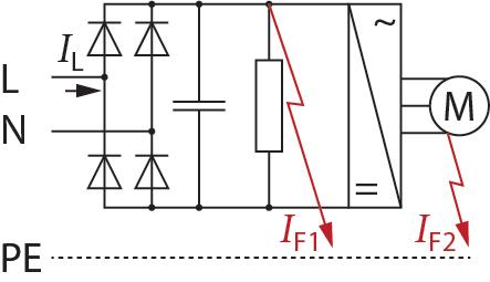
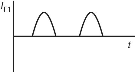
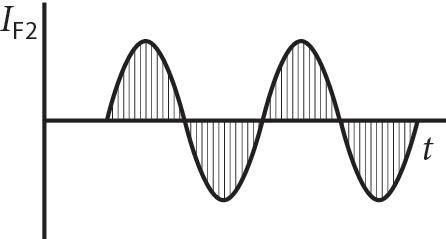

An insulation fault IF1 on the DC side of the bridge rectifier produces a pulsed residual current at the fundamental (mains) frequency This pulsed current may be superimposed on a smooth DC component, the effective value of which is related to the DC link voltage, smoothing capacitance, and fault resistance.
*Note: Limits for smooth DC fault current: ≤ 10 mA Type F or > 10 mA Type B Type F RCDs do not trip on smooth DC Do not use for smooth DC fault current > 10 mA.
A fault IF2 located on the output stage (supply to motor) results in a residual current containing multiple frequency components This is referred to as a composite residual current for design/test purposes (see the table below, left). The composite residual current components have relative values defined at the specific frequency; mains frequency, the motor frequency at 10 Hz, and inverter switching frequency at 1 kHz These values of 10 Hz and 1 kHz represent the most severe condition for Type F RCD tripping, providing reliable operation and effective protection when using Type F RCDs HP design limits for use of Type F checked through equipment design calculations and testing:
● Ratio of composite leakages current components compared to RCD sensitivity IAn
● Minimum motor speed control setting (frequency) 10 Hz
● Maximum inverter switching frequency < 1 kHz
● Maximum smooth dc fault current limit < 10 mA
If the equipment design characteristics cannot be guaranteed to meet the Type F limits, use Type B instead.
Type B RCD unexplained tripping
Reports of unexplained Type B RCD tripping when associated with HPs could be linked to RCDs which are only designed to work up to 1 kHz (currently to meet BS EB 62423, manufacturers only need to test < 1 kHz.
Refer to the manufacturer’s Type B RCD technical characteristics, to verify that they are suitable for use with modern HPs These commonly produce leakage currents < 1 kHz Getting it wrong can be an expensive mistake!
HP inverters with switching frequency in the region of 2 < 16 kHz naturally produce higher leakage currents at higher frequency as a result of circuit capacitance Type B RCDs that are only designed to work < 1 kHz may trip unexpectedly when subjected to leakage currents above this value (see diagram, right).
Greener homes require smarter solutions (equipment) than those traditionally associated with the simplicity of our old domestic installations This, in turn, requires a better knowledge of the individual characteristics of the equipment we’re intending to supply with electricity
Planning, checking and verification before attending site is a pre-requisite for a quick, safe and reliable installation
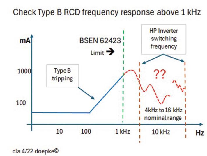
cla
As with any complex equipment, HP characteristics vary from one manufacturer to another Consequently, the design of the electrical supply requirements and associated protection devices may differ This must be considered in conjunction with the individual site design requirements, based on BS 7671 It is simple if you do it right –look, check, ask, think, do!
To operate reliably and provide years of trouble-free service, HPs require a reliable electrical supply The duty of care is shared between the HP manufacturer/UK supplier and the electrical installer This can be met with a bit of planning,
checking and discussion, if necessary, prior to installation.
Big metal boxes mounted outside and supplied with electricity represent a potential hazard To reduce the risk of an accident, the electrical installation and method of protection (ADS), must meet the specific requirements of BS 7671, to the letter.
“Planning, checking and verification before attending site is a pre-requisite for a quick, safe and reliable installation.”


Jake Green, Head of Technical Engagement at Scolmore Group, gives a brief overview of the general range of conditions detailed in Section 522 of BS 7671, which an installer will have to consider as they select a suitable wiring system for an electrical installation.
One of the fundamental principles detailed in Chapter 13 of BS 7671: 2018 (including amendments) is ‘Environmental conditions’ Simply stated, Regulation 132 5 1 requires that ‘the design of the electrical installation shall take into account the environmental conditions to which it will be subjected’.
Section 522 of BS 7671 details those environmental conditions that need to be considered when selecting and installing wiring systems The scope of the section is wide ranging, covering the following:
Requires the designer/installer to ensure that installed equipment is suitable for both the minimum and maximum temperatures reasonably expected. Account should also be taken of the maximum temperature expected under fault conditions (522 1)
Electrical equipment must be protected from the detrimental effects of specific heat sources. This might be by shielding,
distancing from the source, having equipment capable of managing the level of heat or local reinforcement or substitution of insulating material (522 2)
Presence of water or high humidity
Electrical equipment must be suitably protected from ingress by water and/or the build-up of condensation The Unicrimp Q-Nect series ( junction boxes, connectors and connection boxes) provides a range of IP66 to IP68 products, providing the designer/installer with suitable options when selecting equipment for use in the presence of water (522 3)
Presence of solid foreign bodies
Requires the wiring system to be capable of minimising the danger arising from the ingress of solid foreign bodies The IP rating should be suitable for the nature of the foreign bodies (522 4)
Presence of corrosive or polluting substances
Requires due account to be taken of materials/substances likely to cause corrosion or deterioration of the wiring system This can be water (rust), presence of dissimilar metals or more obvious corrosive substances (522.5).
The wiring system must be capable of withstanding damage caused by mechanical stress such as impact, abrasion, penetration, tension, compression during installation as well as being protected from impact as part of the fixed installation (522 6)
Vibration
Requires a wiring system to be supported in such a way that due account is given to
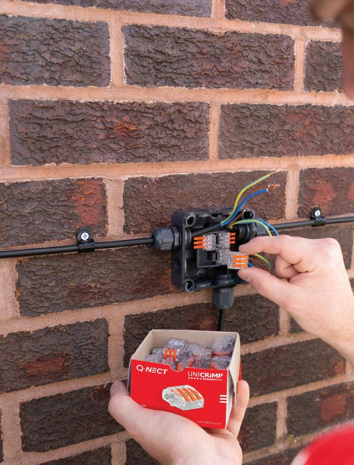
the likely vibration that will exist This may require, for example, use to be made of saddle clips rather than standard cable clips where a cable is not installed within a cable management system (522.7).
Other mechanical stresses
Requires a wiring system to be selected and erected to avoid during installation, use or maintenance, damage to the sheath This requires use to be made, where necessary, of correct saddles, clips and the like to support cables to avoid damage to the cables and terminations Furthermore, amongst other things, buried cables should be suitably marked with tape/cable covers (522 8)
Presence of flora and/or mould growth
Requires the designer to take account of the effects of plants, trees and the ingress of mould growth (522 9)
Presence of fauna
Recognises that wildlife can have a serious negative impact on an installation Rodents can gain access through very small openings; large animals can cause significant damage to cables and the like. Designers and installers must make use of both suitable wiring systems and correct locations to avoid damage (522 10)
Solar and ultraviolet radiation
Where solar or ultraviolet radiation is likely to have a significant effect, a suitable wiring system must be selected and erected or properly shielded (522 11)
Seismic effects are unlikely to be an issue in the UK (522 12)
Movement of air (522 13) and Nature of processed or stored materials (522 14) are covered in other parts of BS 7671
Building design
Requires the designer to take due account of where structural movement is likely to exist and potentially create excessive mechanical stress. This typically happens in larger and taller buildings where relative movement is required as part of the build (522 15)
This article has only touched upon the various environmental factors to be considered by designers and installers. Reference should also be made to Appendix 5 of BS 7671 for the applicability of the various codes detailed in Section 522

OR DOWNLOAD THE



Frank
BS 7671 and requirements for voltage drop
The topic of voltage drop is covered within section 525 of BS 7671 as well as in Appendix 4 section 6.4, where details are provided regarding the requirements and maximum limitations for use with electrical installations.
For low voltage installations, the voltage drop values are found in Appendix 4 of BS 7671, for those fed from a public distribution system, the values shown in Table 1 apply.
In cases where the client has their own generator or transformer, and where the electrical distribution system is not a public supply, voltage band control will be the responsibility of the client. When this happens, values of voltage drop can be increased, as seen in Table 2
The specified lower equipment voltage limit means that the installation voltage at the terminals has to exceed that lower value in accordance with Regulation 525.1.
In the absence of a product standard for fixed current-using equipment, the installation voltage at the terminals will not impair the safe functioning of that equipment under the requirements of Regulation 525.201.
Considering voltage drop in the design involves taking into account the electrical installation and circuit type. According to Table 1, for a DNO supply, lighting circuits are at 3% of the nominal 230 V single-phase supply voltage, and the voltage drop must not exceed 6.9 V.
All other circuits are at 5% and the voltage drop must not exceed 11 5 V
The tables in Appendix 4 of BS 7671 contain a voltage drop section in which the millivolt per amp per metre (mV/A/m) of a particular cable may be obtained For example, Table 4D5 should be used for thermoplastic insulated and sheathed flat cables with copper conductors
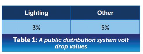
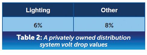
An electrical load of 6 kW for a motor circuit is to be supplied at 230 V by a PVC insulated and sheathed PVC T&E cable of 20 metres in length
The cable is clipped on the surface through an area with an ambient temperature of 40°C and is grouped with three other cables of similar size and loading The protection is provided by a BS 60898 Type B circuit breaker
“Considering voltage drop in the design involves taking into account the electrical installation and the circuit type.”
We need to determine the following before we can establish whether the volt drop is satisfactory:
1. The circuit design current (Ib)
Design Current Ib = Watts / Voltage Ib = 6000/230 = 26 A
2. The rated current of the protective device (In)
The rating of the protective device needs to be equal to or greater than the design current of 26 A Therefore, a 32 A BS 60898 Type B circuit breaker would be selected.
In = 32 A
3. The tabulated current value of the cable (It)
Tabulated Current It = In / Correction Factors
The next step is to apply any correction factors. In the worked example we need to consider the ambient temperature (Ca) and grouping (Cg)
The factors are then applied to the following formula:
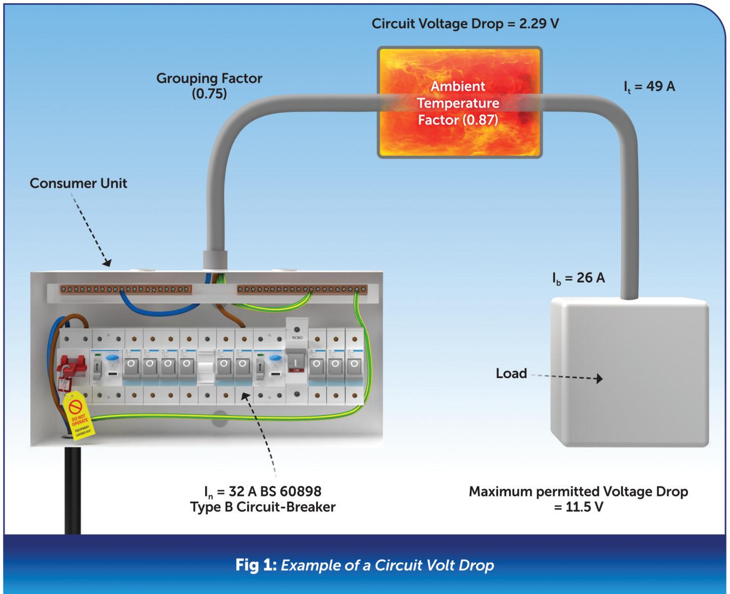
It > In / Ca x Cg
From Table 4B1 (BS 7671) Ca = 0.87
From Table 4C1 (BS 7671) Cg = 0 75 (4 circuits, Reference Method C)
It > 32 / 0 87 x 0 75
It > 49 A
It is now time to select a cable size that is capable of carrying 49 A.
From Table 4D5 (BS 7671) Reference Method C, Column 8, we can select 10 mm2, which is rated at 64 A
At this point, we can work out our volt drop and determine whether it is satisfactory Using the same table and conductor size, we can calculate the millivolt amps per metre value
Volt drop from Table 4D5 (BS 7671), 10 mm2 Cable, Column 9 is 4 4 mV/A/m By using the volt drop formula below, we can now add our mV/A/m value, the design current (Ib) and the cable length (L)
These values are multiplied together and then divided by 1,000, to convert from millivolts to volts, as shown in Fig 1
Volt drop = (mV/A/m) x Ib x L / 1000 Volt drop = 4.4 x 26 x 20 / 1000 Volt drop = 2 29 V
The maximum volt drop for this circuit is 11 5 V, as discussed above Therefore, the actual volt drop of 2 29 V is below the permitted value and is, therefore, satisfactory.


Most electricians might assume that the use of fuse-protected leads is unnecessary when carrying out ‘dead’ testing on circuits proven to be de-energised by a recognised safe isolation procedure. Equally, many might think that such leads are always required when testing energised circuits or equipment. This article from the experts at NICEIC discusses the issues that will influence the decision as to whether or not fused leads need to be employed when using electrical test instruments.
The general safety requirements for electrical test instruments are given in the BS EN IEC 61010 series of standards (Safety requirements for electrical equipment for measurement, control, and laboratory use), with the specific requirements for hand-held and hand-manipulated probe assemblies for electrical test and measurement covered by BS EN IEC 61010-031 Conformity with the relevant parts of
“It should be noted, however, that such instruments do not protect against faults occuring between a single test lead and earth when the test probe is connected to an energised circuit...”
this multi-part standard satisfies the product certification requirements of the Low Voltage Directive and the corresponding UK Electrical Equipment (Safety) Regulations 2016
More specific requirements for electrical test instruments are given in the relevant parts of the BS EN 61557 and BS EN IEC 61557 series (Electrical safety in low voltage distribution systems up to 1,000 V AC and 1,500 V DC Equipment for testing, measuring or monitoring of protective measures). Neither of these series of standards specifically requires the use of fused test leads for a particular application
instruments and leads
If an instrument for testing continuity, insulation resistance, loop impedance, earth electrode resistance or any combination of these conforms to BS EN IEC 61010 or BS EN 61557 / BS EN IEC 61557, it should not be necessary to use fused leads since safety is intrinsic within the design of the instrument when used in conjunction with
the leads supplied with the instrument
It should be noted, however, that such instruments do not protect against faults occurring between a single test lead and earth when the test probe is connected to an energised circuit, for example if a test lead were to be trapped in an electrical cabinet door
In the case of those tests that are intended to be carried out with the installation de-energised, there should be no risk of electric shock if the circuit or equipment under test has been isolated using an appropriate safe isolation procedure1
The Health and Safety Executive publication Electrical test equipment for use on low voltage electrical systems (GS38) gives guidance on the safety requirements for the design of test probes and leads for use with test instruments, test lamps and indicators used to detect the presence (or absence) of voltage Although not specifically intended, this guidance is often applied to leads used with other test instruments.
“In the case of a test to establish the presence or absence of voltage, the use of a proprietary test lamp or 2-pole voltage detector suitable for the working voltage is preferred (paragraph 19 of GS38 refers).”
While the leads provided with a test instrument meeting the requirements of the relevant parts of BS EN IEC 610101 or BS EN 61557 / BS EN IEC 61557 should be adequate for the intended use of the instrument, this might not be the case for an instrument that does not conform to those standards. In such cases, the use of fused leads is recommended.
“Where there is any doubt as to whether the presence of fuses and/or resistances in fused lead sets will adversely affect the functionality or safety of the test instrument the advice of the manufacturer should be sought.”
In the case of a multimeter, an incorrect range setting could be selected inadvertently, allowing an excessive current to pass through the instrument and leads It is for this reason that GS38 recommends (in paragraph 21) that fused leads should be used with such test instruments
It should be noted, however, that merely using fused leads with an otherwise unsuitable test instrument will not necessarily make it safe to use
In the case of a test to establish the presence or absence of voltage, the use of a proprietary test lamp or 2-pole voltage detector suitable for the working voltage is preferred (paragraph 19 of GS38 refers)
It is essential that the leads for use with any type of test instrument that are intended to be applied to live terminals at low voltage are inspected prior to each use to confirm that they remain in a satisfactory condition
Regardless of whether fused or unfused leads are used, the length of exposed tip on the test probes should be kept as short as possible to minimise the possibility of arcing, flashover or electric shock occurring
GS38 recommends that probes are insulated to leave no more than 4 mm and, where practicable, only 2 mm or less of exposed tip. Alternatively
spring-loaded, retracting shields may be used (paragraph 9 refers)
Where there is any doubt as to whether the presence of fuses and/or resistances in fused lead sets will adversely affect the functionality or safety of the test instrument the advice of the manufacturer should be sought
www hse gov uk/pubns/books/gs38 htm
Summary
Where a multi-functional test instrument is used for verification, conforming to BS EN IEC 61010 or BS EN 61557 / BS EN IEC 61557, it is not usually necessary to use fused leads since safety is intrinsic within the design of the instrument and when used with the test leads supplied with the instrument
However, such instruments do not provide protection against faults occurring between a single test lead and earth when testing an energised circuit
W h e r e a t e s t i n g i n s t r u m e n t d o e s n o t
c o n f o r m t o t

If aliens were to bend their ears towards Earth and hone in on the lighting industry (stick with us for a moment on this!), the word ‘circularity’ and its many variations would be picked up fast
“The closed-loop system”, “exchangeability”, “cradle-to-cradle products”, “modular design” – all these commonly used phrases point towards the same sustainable strategy of circularity
The aliens will think this is great news –humans don’t want to destroy the planet! – and, in many significant ways, it is. We’re all speaking the same language of sustainability; it’s front of mind across the lighting industry; we’re a community that shares common values But there’s been something fundamentally lacking from much of this discussion – verification
That’s why the TM66 Assured Product Verification Scheme was developed by the Chartered Institution of Building
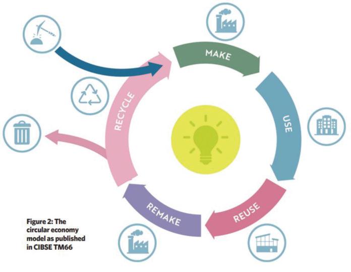
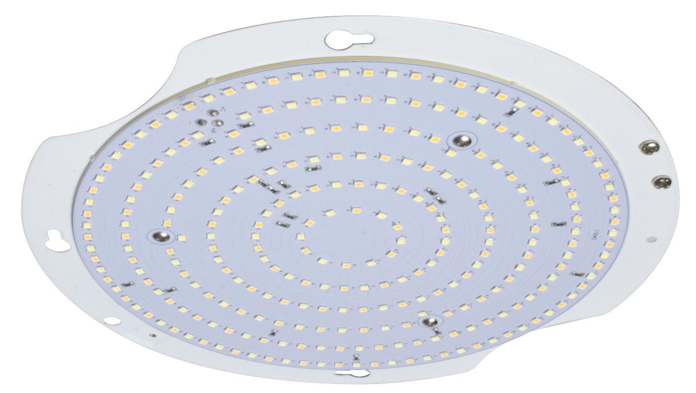
Are you asking manufacturers for product circularity ratings? The team at ROBUS explain more about why this is such an important consideration for lighting installers.
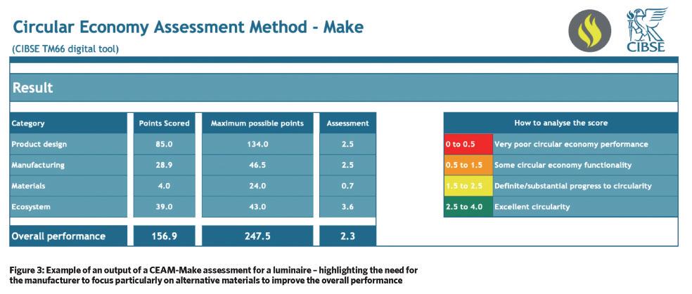
Services Engineers (CIBSE) and the Lighting Industry Association (LIA)
How do we identify, implement, and verify circularity?
In October 2021, CIBSE released the Technical Memorandum 66, or TM66 as it has come to be called
This document serves as an in-depth guide aimed at helping specifiers and manufacturers in the lighting sector comprehend and implement the principles of the circular economy
It has four key objectives:
● Promoting sustainable design
● Ensuring material traceability
● Encouraging repair and reuse
● Enabling responsible recycling
Guidance is great, but verification is what sets the standard and that’s what the TM66 Assured Product Verification Scheme is all about.
This scheme adds an additional layer
of credibility and verification to the already comprehensive TM66 toolkit
Significantly, it introduces a new metric: the TM66 circularity rating.
You can ask manufacturers for circularity ratings Through engagement with the TM66 Assured Product Verification Scheme, lighting manufacturers can obtain independent verification of their circularity claims This validation procedure ensures that the ratings offered by manufacturers for their lighting fixtures are accurate, unbiased, and standardised This means you can now compare products from different manufacturers on a like-for-like basis
How does TM66 Assured certification work?
Manufacturers wishing to submit products for certification are required to provide product details in specified formats One such format is the Circular Economy Assessment Method (CEAM), which assesses the circular economy qualifications of lighting products across the supply chain
In practice, the assessment is broken down into parts such as product design, manufacturing, materials, and ecosystem and, for each part, there are specific questions, examples, and evidence required
to inform the overall scoring system
Required documents for submitting to TM66 Assured are:
● Completed CEAM, consisting of 72 questions,
● Supporting evidence to validate information provided,
● All product instructions and product packaging,
● The complete product.
It helps to get guidance from the experts, which is why comprehensive training on conducting TM66 Assured assessments is available through the LIA
TM66 Assured is voluntary, not mandatory
Indeed, TM66 is not mandatory which can sometimes prevent substantial uptake However, many manufacturers are championing this assessment model ROBUS recently submitted two products for verification – the GOLF surface fitting and SELEST floodlight
SELEST meets sustainable design standards because it’s designed for longevity, with a high impact rating, a self-regulating valve to prevent moisture condensation and an exceptionally high efficacy of 123Lm/W – 162Lm/W
GOLF has a modular design, which refers to a product design strategy that involves creating a complete product by assembling smaller, independent components This approach promotes recycling and decreases landfill waste by making it easier to disassemble and reuse parts
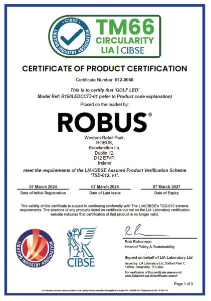
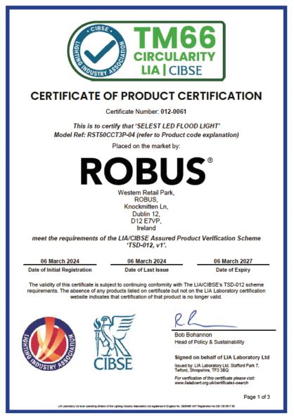
Both GOLF and SELEST achieved a strong rating of 1.8 which is defined as showing definite/substantial progress towards circularity Beyond the rating, the TM66 assessment process provides practical insights for implementing circularity into product development ROBUS has incorporated these learnings into its new product development processes.
TM66 Assured certification is valid for three years and can be showcased in various forms, such as being listed in the LIA database Additionally, the LIA is distributing logos that vendors can display on their websites and attach to their products as a symbol of approval
So, as you navigate the lighting industry's evolving landscape, keep an eye out for these logos they're a beacon of trust and a testament to a commitment towards sustainable practices!

BROWSE THE 2024 ROBUS LIGHTING CATALOGUE ONLINE AT: WWW.RDR.LINK/EBD015
IN THIS REGULAR COLUMN, DR. TOM BROOKES, MD AT ZZEUS TRAINING AND CHAIRMAN OF THE FSA, ANSWERS YOUR QUESTIONS RELATED TO FIRE SAFETY. HERE HE LOOKS AT COMPLIANCE OF FIRE SAFETY SYSTEMS IF FIRE ALARM INDICATOR DEVICES DON’T MEET THE REQUIRED STANDARDS.
If VAD and VID fire alarm indicator devices do not meet the standards established by EN 54-23, is the system compliant?
There isn’t a simple answer to this question However, in extreme cases, it may not just be non-compliant, it may also be illegal.
Since January 2014, Visual Alarm Devices (VADs) have been mandated to adhere to the standards outlined in EN 54-23. These adjustments by BSI were prompted by the UK Equality Act of 2010, aimed at legally safeguarding individuals from discrimination in the workplace These regulatory updates have generated uncertainty regarding the use of combined sounder beacon devices, which are required to meet these standards for the beacon component
Ensuring effective emergency alert systems for individuals with hearing impairments is paramount in any safety system With millions of individuals in the UK facing challenges related to hearing loss, reliance solely on audible alarms becomes inadequate To address this, integrating visual alarm systems becomes imperative.
The first step is to consult with the client and check their fire risk assessment The client or their assessor may have good reasons for having EN 54-23 compliant VADs that you may not have considered – there could be many hearing impaired people in the building, for example
Viewing this document is key for anyone designing a fire alarm system, as putting less safety equipment in the building than the fire risk assessment states could result in you having to explain why you went against the assessment in a court of law, should there be a problem at a later date.
A VAD serves as a fundamental component in emergency signalling, providing clear visual cues during critical situations to facilitate prompt evacuation Versatile in application, VADs can be installed indoors or outdoors, mounted on walls or ceilings, and utilised either independently or as part of a larger alarm network.
VADs play a pivotal role in environments characterised by high ambient noise levels, such as industrial settings, or where individuals employ hearing protection devices Moreover, they significantly enhance accessibility for those with hearing impairments, ensuring inclusivity across public spaces, offices, educational institutions, and toilet and bathroom facilities These must comply with BS EN 54-23
In contrast, Visual Indicating Devices (VIDs) serve a supplementary function within alarm systems VIDs should be an addition to existing fire alarm devices but must not serve as standalone systems due to their inability to facilitate evacuation procedures Common applications include exterior installation to aid Fire & Rescue Services, providing coded visual signals for staff, or serving


as remote indicators to pinpoint emergency locations
Where I see people most commonly getting this wrong is within disabled toilets and bathrooms – if there is a need for a visual indicator in a disabled facility it needs to be a EN 54-23 VAD, as a standard beacon would not meet the client’s obligation under the UK Equalities Act 2010
Consequently, adherence to EN54-23 criteria mandates the installation of VADs to cater to individuals with hearing impairments effectively However, in certain scenarios where EN 54-23 compliance is not obligatory, such as those identified during risk assessments, the utilisation of VIDs might be considered
So, in simple terms, if the visual alarm device is likely to be the primary means of indication it needs to comply with EN 54-23, but if the visual alarm is for secondary purposes it may be a VID (standard beacon)

DO YOU HAVE A QUESTION YOU'D LIKE ANSWERED?
EMAIL YOUR QUERIES TO: TOM@ZZEUS.ORG.UK

GET MORE DETAILS ABOUT ZZEUS TRAINING AND THE RANGE OF COURSES ON OFFER AT: WWW.RDR.LINK/EBD017

KEEPING THE LIGHTS ON
Siemens S4 Switchboards, MCCB Panelboards and MCB Distribution Boards are now available through selected Electrium
Authorised Distributors, find out more: electrium.co.uk





T&E Cable Clips Tub (Plastic & Metal) • Clout Nails • Red Plastic Wall Plugs & Squarelock Woodscrews
Red Plastic Wall Plugs & Countersunk Screws • Brown Plastic Wall Plugs & Countersunk Screws
Cavity/Plasterboard
Panhead Screws








The experts at NAPIT discuss site preparation and resistance to both contaminants and moisture.
The sealing of wiring systems is detailed in Regulation 527 2 1, which specifies the requirements for wiring systems that pass through building construction, such as floors, walls, roofs, ceilings, partitions and cavity barriers.
Although this regulation is located in a section that is concerned with minimising the spread of fire, it is detailed further in Regulation 527 2 4, which discusses resisting external influences, such as water and moisture. In Appendix 2, references are provided to the Statutory Regulations, particularly bullet (ii) Buildings, which lists the Building Regulations in England, Wales, Scotland and Northern Ireland Building Regulations have documents and handbooks to further explain the requirements:
● Approved Document C – England 2004, including 2010 and 2013 amendments
● Approved Document C – Wales 2004, including 2010 and 2017 amendments
● Technical Handbook – Scotland June 2023 Edition
● Te c h n i c a l B
I r e l a n d 2 0 1 2
These documents are sometimes overlooked by electricians when undertaking installations in domestic properties and you may be caught out by your astute local building control officer who may bring the relevant statutory documentation to your notice
Approved Document C has Item 6.12 which states:
To avoid excessive moisture transfer to roof voids, gaps and penetrations for pipes and electrical wiring should be filled and sealed; this is particularly important in areas of high humidity, e g , bathrooms, shower rooms and kitchens. An effective draught seal should be
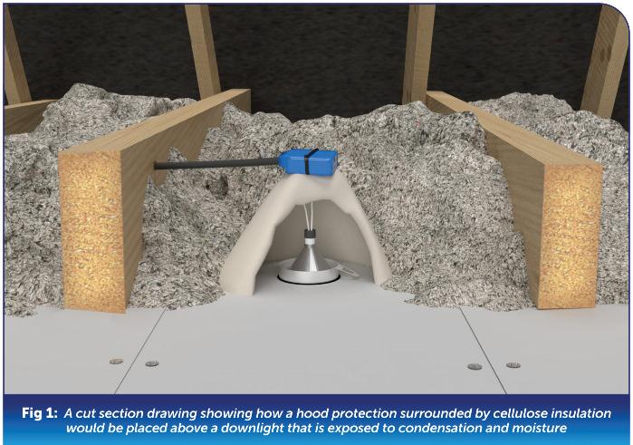
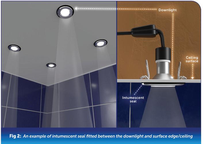
provided to loft hatches to reduce inflow of warm air and moisture
The Technical Handbook states in 3 15 5:
A floor, wall, roof or other building element should minimise the risk of interstitial condensation in any part of a dwelling that it could damage Walls, roofs and floors should be assessed and/or constructed in accordance with Section 8 and Annex D of BS 5250: 2002.
Although it isn’t as detailed as the Technical Handbook, the Technical Booklet C states in 8 2:
A dwelling should meet the requirement to avoid any harmful effects caused by interstitial condensation if it is designed and constructed in accordance with BS 5250
It is the Building Regulations that provide information regarding the building materials and workmanship required to satisfy both conditions:
● Materials are of a suitable nature and quality in relation to the purposes and conditions of their use
● Workmanship is such that, where relevant, materials are adequately mixed or prepared and applied, used or fixed so as to perform adequately the functions for which they are intended
If downlights are installed in bathrooms, shower rooms, or other areas of high humidity, an open backed downlight, even if there is no living accommodation above, or even a fire-rated downlight, would not be the first choice, see Fig 1.
In areas of high moisture content, electricians and specifiers should consider a moisture resistant downlight An IP65 rated fitting with an adequate intumescent seal would be adequate, see Fig 2
This applies even if the ceiling below which they are installed is outside of zones 1 and 2 and is at a height exceeding 2 25 metres in locations containing a bath or a shower.
The light fittings that meet these requirements are widely available from a range of suppliers


Rhys Jones, National Technical Manager at National Ventilation, explains how ventilation system design can be made simple for electricians who are keen to install MVHR but aren’t sure how to design and specify this technology.
The latest Part F and Part L of the Building Regulations are designed to help the UK deliver Net Zero, including a reduction of almost a third less carbon for new homes But, as buildings become more airtight, to improve efficiency and help achieve this goal, it’s crucial to consider indoor air quality (IAQ) too
The new Part F is therefore seen as a vital development since it sets out important changes, which will accelerate the move towards low carbon ventilation as an industry standard while improving IAQ For new build residential homes, the new Building Regulations require higher rates of ventilation to protect resident health. This means a move to more advanced ventilation solutions, such as mechanical ventilation with heat recovery (MVHR)
With MVHR increasingly the ventilation system of choice for new build projects now is the ideal time for electricians to take advantage of this growth through projects in small housing development plots However, electricians will need to be familiar with the design and specification of technologies such as MVHR
So, what steps do electricians need to take to design and specify a ventilation system?
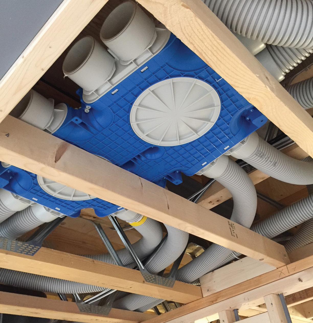
The first step in designing a ventilation system is to obtain the drawings from the architect or developer This is needed to specify the correctly sized ventilation unit and the correct type and lengths of ducting, whilst ensuring it complies with Building Regulations
The architect drawings and property details, including room dimensions, are then entered into an airflow calculator This ensures that the ventilation specified can meet the airflow demands of each room. Once the total airflow
figure is calculated an MVHR unit can be selected to meet this need to help improve indoor air quality and reduce space heating costs
It’s vital to specify the correct unit for a property as different MVHR units will offer different configurations. It’s also important to design a system that will provide the correct levels of ventilation and will physically work within the structure If the system is designed to ensure the MVHR unit is never working at more than 75% of its maximum capacity, this will help it work quietly and efficiently.
The next step is to decide where best to locate the MVHR unit. The loft is an ideal location for the MVHR but in properties with vaulted ceilings an alternative location is needed, such as a utility room or a plant room
Next it’s important to work out where to locate risers and ducting. You need to consider the building design and whether the ceilings have voids to run the ducting or alternatively webbed eco joists where the ducting can be run However, if these aren’t an option, electricians can consider other solutions such as running the ducting between floors or within stud walls.
When it comes to MVHR systems electricians can be put off by the arduous and specialist nature of traditional plastic ductwork but there is now a cost-effective, simple alternative Semi rigid ductwork, such as National Ventilation’s Monsoon Radial ducting, is ideal for smaller developments since it is flexible but robust and is up to 60% quicker and easier to install, with a Stanley knife the only real tool needed to install it
This type of ducting also ensures fewer mistakes, since even a novice can install it to a high standard, resulting in an airtight installation and improved system performance With a plethora of plenums and accessories this system can overcome over 99% of issues that may occur on-site
The next step to consider is controls. Traditionally MVHR is often boosted on bathroom lighting, however, not every bathroom visit is a shower or a bath and so systems can boost unnecessarily
An alternative, more efficient control method is an in-duct humidistat fitted in the ducting, which means the boost only triggers when humidity rises An in-duct humidistat also takes less time to install and is more cost-effective since less wiring is needed to install it as electricians only need to wire the humidistat back to the fan since the fan is constantly on, drawing air from the bathroom.
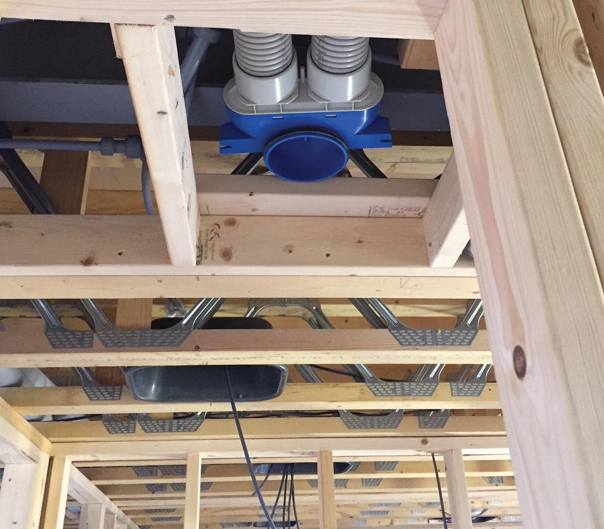
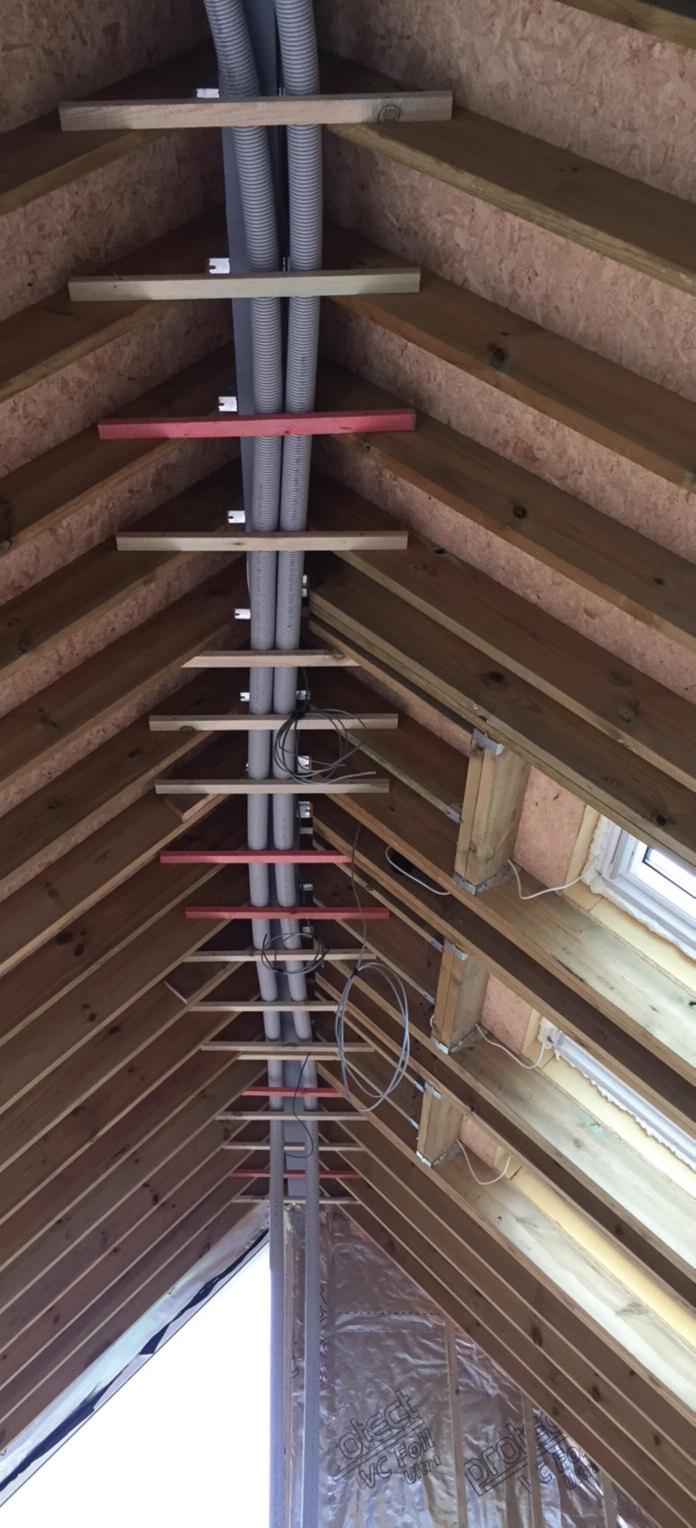
Once the design is complete it should include detailed calculations, proposed ducting layout, where to put the MVHR unit and risers and how to control the unit
However, although a design may appear correct on paper it’s vital to ensure a design works on-site
Often plans only tell half the story and you can be caught out if things such as steels don’t show up on the original plans
The knock-on effect of this can be a need for additional materials that haven’t been considered in the original calculations
Fortunately, there are ventilation design services available, such as the free service National Ventilation offers, to help electricians with their MVHR ventilation designs To take up the free design service architects, developers and electrical professionals can visit: www.nationalventilation.co.uk/ design-service/


Although the highlighted issue was the enclosure (or lack of!) on the RCBO, there are several other obser vations that would need to be documented on the EICR
The lack of an enclosure for the RCBO would create several obser vation codes. This installation appears to have been subjec t to a new smar t meter installation, where the smar t metering installer has placed a see -through plastic sheet as a temporar y cover over the offending RCBO
The RCBO itself has been connec ted via the main switch of the lef t-hand consumer unit via the four- core flexible cable Flexible cables aren’t suitable for fixed wiring unless they meet the requirement of Regulation 521 9 1 The green and yellow conduc tor of the

four- core flexible cable has been utilised as a neutral conduc tor The reference conduc tor of the RCBO has been connec ted to the ser vice head neutral/ear th terminal which is only for use for termination of the ear thing conduc tor.
The S olar PV installation has single insulated conduc tors exposed at the meter tail connec tion blocks where the sheath of the t win and ear th cable has been removed. The use of an AC t ype RCD for the circuit supplying the S olar PV and the provision of a second circuit-breaker shared with the RCD supplying the S olar PV is not permitted The cable connec ted to the S olar PV generation meter has the sheath removed, exposing the single
insulation apparently to permit the cpc to be terminated
The AC isolator does not meet IP requirements of Regulation 416 2 2 with t wo flexible cables entering the top of the isolator.

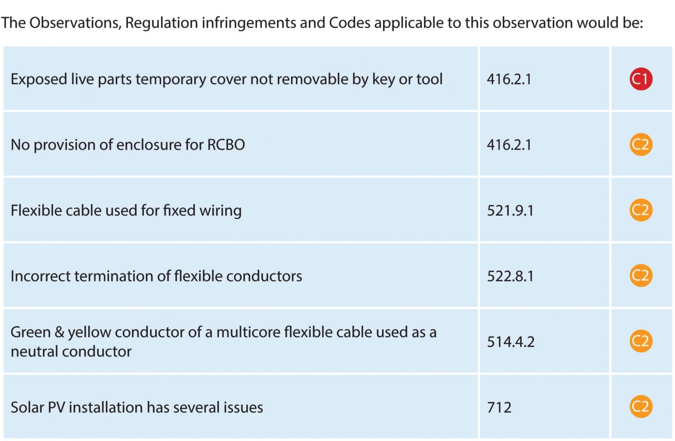
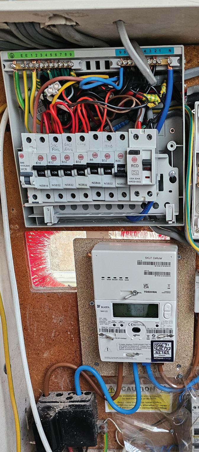

GET THE BOOK AND CRACK THOSE
Updated for BS 7671:2018+A2:2022, NAPIT ’s EICR Codebreakers publication is purpose -written to aid contractors, inspectors and clients, and now includes updates to align with Amendment 2 of the IE T 18th Edition Wiring Regulations The book is the per fect technical aid for electrical professionals and their customers.


Need help with cracking those all-impor tant EICR codes? Ever y month the technical team at NAPIT will be studying your latest ‘Caught on Camera’ photos and offering advice on the next steps, should you find a similar installation. If you want the team at NAPIT to help crack your codes then send your pic tures through to us at: pe@hamer ville.co.uk


NICK JAMES: A FRIEND OF MINE HAS A LANDLORD WHO TOLD HIS MATE TO COME ROUND AND FIX A FAULT Y FAN. THIS IS THE RESULT
The number of occasions when unqualified or incompetent people dabble with electrical installation never fails to amaze our industr y This type of quick fix can result in a serious injur y or worse.
Whatever the reason for the fault on the extract fan, a proper investigation by a ‘sk illed person’ was required to determine the issue and to find a suitable solution in accordance with the requirements of BS 7671
The installation of a temporar y connection such as the twin and ear th floating from the light is not only unprofessional, it is highly dangerous. The single insulated conductors are exposed at the light fitting and the extractor fan and the cpc has not been utilised The cable can be pulled by someone using the facilities, causing the cable to become damaged or loose Due to the incorrect cable installation, water can penetrate into the top of the extract fan
This is an area where immediate action would be required to remove the danger. Although this would normally be a classification code C2, which is still an unsatisfactor y outcome of the EICR, the consequences of any fault occurring could result in serious injur y or a fatality
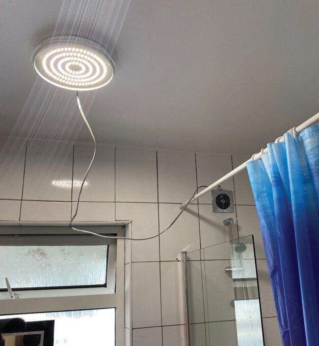

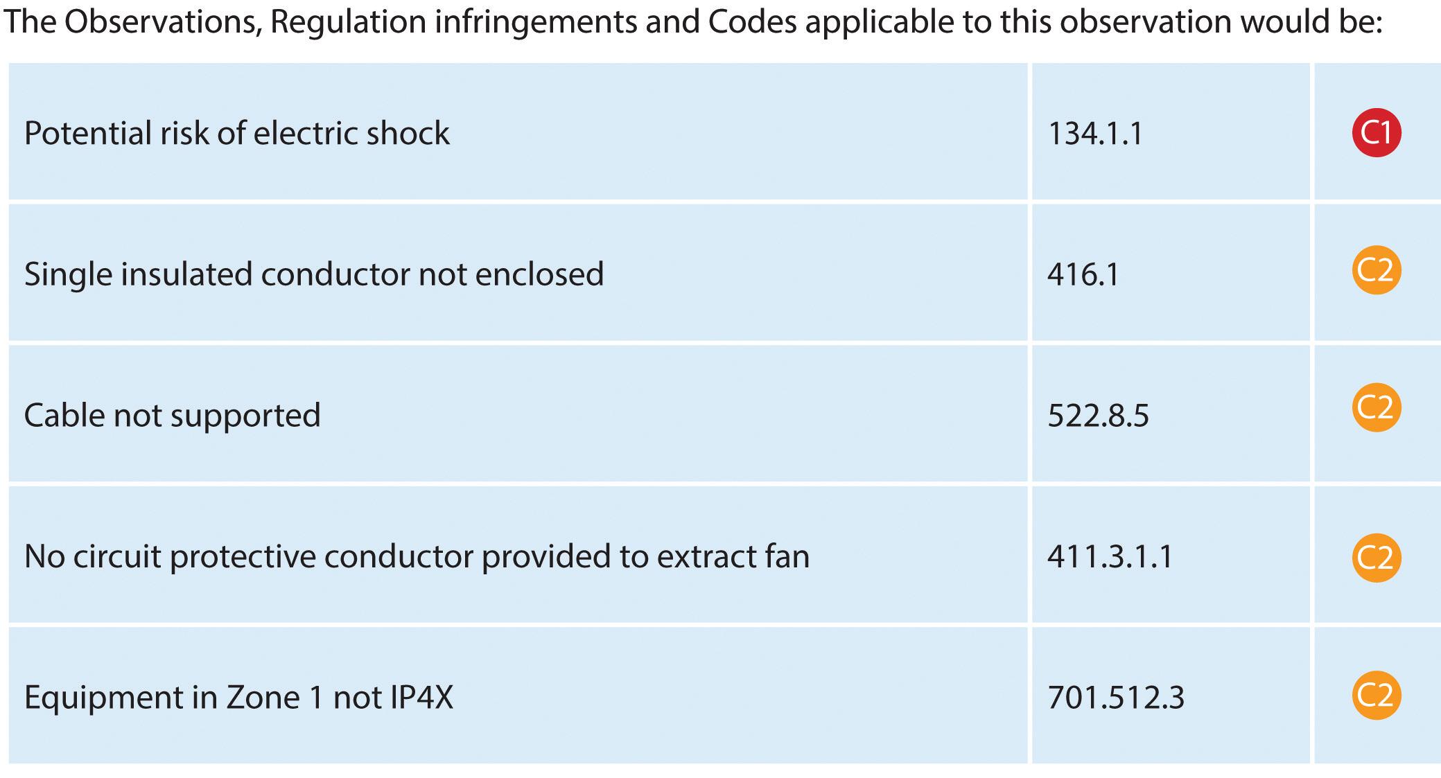


The A2:2022 18th Edition Codebreakers publication is priced at £22.00 (members) and £24.00 (non-members). It is available in both hard copy and digital versions * Price is VAT exempt and excludes postage and packaging.

ORDER YOUR COPY OF NAPIT CODEBREAKERS BY VISITING: WWW.RDR.LINK/EBD013


Julian Grant of ChauvinArnoux UK provides a guide to navigating the subject of power quality and energy efficiency.
U N D E R STA N D I N G TOTA L H A R M O N I C D I
Modern world electronic products, appliances and devices generate current harmonics which can affect the operation and efficiency of an installation and the equipment in it
Put simply, harmonics are currents in an electrical system at frequencies that are whole-number multiples of the supply frequency In other words, if the supply is 50Hz, the harmonics are currents at 100Hz, 150Hz, 200Hz and so on Generally, harmonics are considered up to the 50th order or 2500Hz.
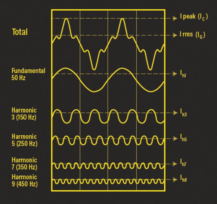
Total harmonic current distortion or THDi is a measure used to indicate the amount of harmonic distortion present in an electrical installation This is a ratio of the sum of all the harmonic currents to the current at the fundamental frequency, and is described by the following equation:

“High Power Factor indicates efficient electrical energy use. Low Power Factor and the associated high Reactive Power can cause energy efficiency and equipment reliability issues...”
Harmonic currents add to the fundamental (50 Hz) current in cables and equipment and should be considered in the determination of cable sizes according to BS 7671 – Appendix 4 Current carrying capacity and voltage drop for cables, which references THDi THDi needs to be viewed in relation to the current flow and the circuit or installation capacity A high percentage THDi at low currents may be of little concern, where a lower percentage THDi could be a major problem for a cable or piece of equipment operating near its rated capacity.
N D E R STA N D I N G P OW E R FAC TO R
Electrical equipment, such as motors and other inductive loads, require Reactive Power in addition to Real Power to work effectively.
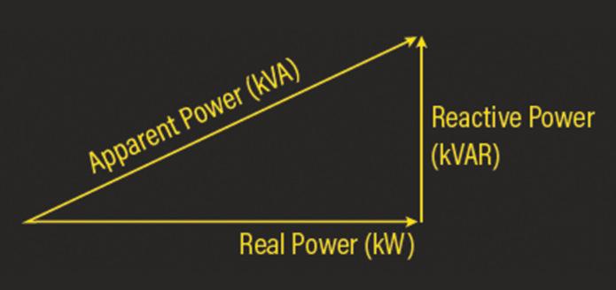
“A high percentage of THDi at low currents may be of little concern, where a lower percentage THDi could be a major problem for a cable or piece of equipment operating near its rated capacity.”
Power Factor is the ratio of Real Power (kW) to Apparent Power (kVA) Reactive Power (kVAR) is the vector difference between Real Power and Apparent Power High Power Factor indicates efficient electrical energy use Low Power Factor and the associated high Reactive Power can cause energy efficiency and equipment reliability issues, and reduced system capacity.
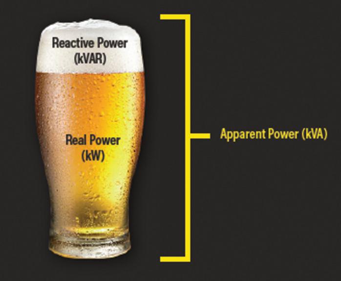
Consider a pint of beer, where the whole glass is Apparent Power, the beer is the Real Power, and the head is the Reactive Power
A full pint with no head would represent a power factor of 1, or unity power factor, with no Reactive Power. In the presence of inductive loads, a Power Factor between 0 95 and 0 98 is generally OK A pint with a nice small head on it!
Poor Power Factor can be improved using Power Factor Correction (PFC) which utilises capacitors to compensate for inductive loads.
Automatic PFC equipment can be used where Power Factor varies as different loads and equipment are used in the installation
If an installation has high levels of harmonic currents caused by equipment such as variable speed motor drives, use of detuned PFC, thyristor switched PFC, or active PFC, may well be required
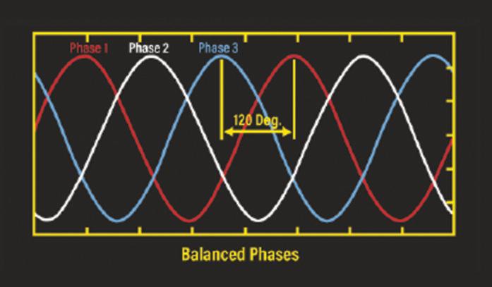
A three-phase power system is said to be balanced when the phase voltages have the same amplitude and are separated by a phase angle of 120˚
Load balance is achieved when the phase currents have the same amplitude and are separated by a phase angle of 120˚
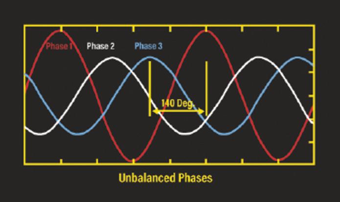
Voltage imbalance describes the situation where the voltage magnitudes, or the phase angle differences between them, or both, are not equal
Voltage imbalances are caused by large differences between the 3 phase currents, which in turn are caused by the poor distribution of large single phase loads
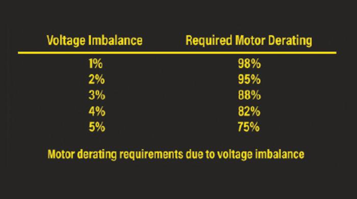
Having balanced phase voltages is important for industrial installations containing 3 phase motors Unbalanced voltages can cause a phase current imbalance up to 10 times the percentage voltage imbalance
Use separate circuits for large single-phase loads connected as close to the incoming supply as possible to reduce the voltage drop on wiring utilised by other equipment
Ensure that all single-phase loads, large and small, are balanced evenly across all three phases

GET MORE DETAILS ABOUT CHAUVIN ARNOUX’S RANGE OF PRODUCTS AND TECHNICAL SUPPORT AT: WWW.RDR.LINK/EBD019
SECTION 6 ENDS! SCAN THE QR CODE TO CLAIM YOUR CPD CREDIT FOR THIS SECTION OR VISIT: WWW.RDR.LINK/EBD020


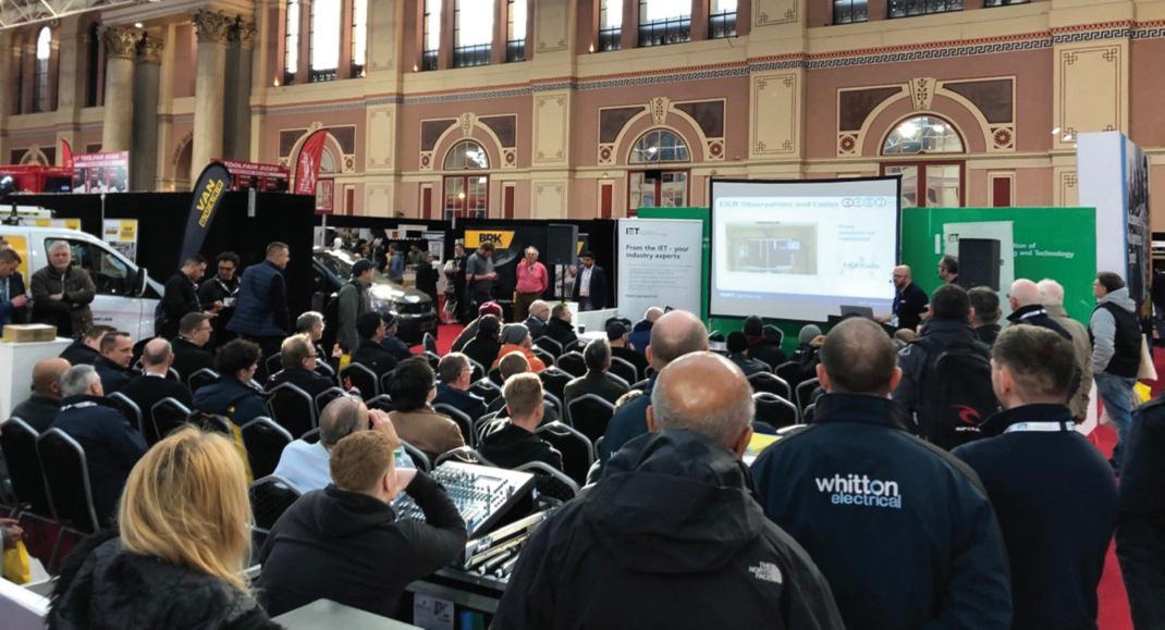

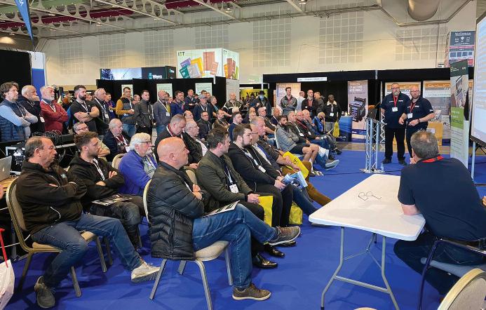
Taking place across two days, the ELEX 2024 tour still has two final stops to make this year. And better still, we’ve got great news for those visitors that are serious about their CPD!
Recent changes to The Electrotechnical Assessment
Specification (EAS) which sets out the minimum requirements for a business to be recognised as technically competent by a Certification or Registration Body, includes a requirement for businesses to maintain appropriate records of qualifications, training (including Continuing Professional Development) and experience.
To support this requirement, EVERY ELEX seminar is now CPD accredited, ensuring those individuals who make the time and effort to attend will receive a direct certificate of completion, which can

form a key part of your ongoing Continuing Professional Development record
With industry regulation and legislation changing constantly, the extensive ELEX seminar programme will cover an array of topics, including the latest Amendment 2 to the 18th Edition and the changes this covers, along with best practice and technical advice for professionals to get stuck into Presentations will be delivered by experts in their field and the only cost to delegates is their time
All seminars will take place in the IET Seminar Theatre located centrally in the exhibition hall and there’s no need for delegates to pre-book, just pre-register to attend the show
Whether you need some advice on the direction the sector is heading, want to chat with manufacturers about their latest solutions, view live demonstrations of the latest products or bag yourself a great
YOUR S H OW, NEA R YO U. . .
● At a venue near you
● Across two days
● Free parking (van friendly)
● Free entry
● Free T-Shirt & a free bacon roll* (*limited to first 1,000 visitors)
● Show bargains
● Hands-on demos
● Meet manufacturers
● Networking opportunities
● CPD accredited seminars and certificates
show deal on tools and equipment from leading brands, your regional ELEX tradeshow has it all
The ELEX 2024 tour will be heading to the CBS Arena, Coventry on 12th and 13th September, before concluding at Sandown Park on November 7th and 8th






















The Fort smart video doorbell that detects important activity


Full 1080p HD Live View, Recording & Visitor Notifications


No Subscription or Additional Fees Required


5m Infrared LED Illumination


3m PIR Detection Range


Battery Powered with up to 750 Activations on Full Charge
Plug-in RF Chime Included


IP54 Rated Ingress Protection


130° Wide Angle Camera View

Motion Activated Video Record (Storage Included)
Clear Two-Way Audio


